


Model UHF-R® Wireless Systems
User Guide
Model UHF-R® Wireless User Guide.......................................................................................... |
5 |
©2010 Shure Incorporated |
|
|
|
27NS14492 (Rev. 1) |
|
|
|
|
|
N108 |
|
Printed in U.S.A. |
|
|
|
|
|
|
English
! IMPORTANT SAFETY INSTRUCTIONS !
1. |
READ these instructions. |
12. |
USE only with a cart, stand, tripod, bracket, or table |
|
2. |
KEEP these instructions. |
|||
|
speci ed by the manufacturer, or sold with the |
|||
3. |
HEED all warnings. |
|
||
|
apparatus. When a cart is used, use caution when |
|||
4. |
FOLLOW all instructions. |
|
||
|
moving the cart/apparatus combination to avoid |
|||
5. |
DO NOT use this apparatus near water. |
|
||
|
injury from tip-over. |
|||
6. |
CLEAN ONLY with dry cloth. |
|
||
13. |
UNPLUG this apparatus during lightning storms or when unused for long periods of |
|||
7. |
DO NOT block any ventilation openings. Install in accordance with the manu- |
|||
|
time. |
|||
|
facturer's instructions. |
|
||
|
14. |
REFER all servicing to quali ed service personnel. Servicing is required when the |
||
8. |
DO NOT install near any heat sources such as radiators, heat registers, stoves, |
|||
|
apparatus has been damaged in any way, such as power-supply cord or plug is dam- |
|||
|
or other apparatus (including ampli ers) that produce heat. |
|
||
|
|
aged, liquid has been spilled or objects have fallen into the apparatus, the apparatus |
||
9. |
DO NOT defeat the safety purpose of the polarized or grounding-type plug. A |
|
||
|
has been exposed to rain or moisture, does not operate normally, or has been |
|||
|
polarized plug has two blades with one wider than the other. A grounding type |
|
||
|
|
dropped. |
||
|
plug has two blades and a third grounding prong. The wider blade or the third |
|
||
|
15. |
DO NOT expose the apparatus to dripping and splashing. DO NOT put objects lled |
||
|
prong are provided for your safety. If the provided plug does not t into your out- |
|||
|
let, consult an electrician for replacement of the obsolete outlet. |
|
with liquids, such as vases, on the apparatus. |
|
10. |
PROTECT the power cord from being walked on or pinched, particularly at plugs, |
16. |
The MAINS plug or an appliance coupler shall remain readily operable. |
|
|
convenience receptacles, and the point where they exit from the apparatus. |
17. |
The airborne noise of the apparatus does not exceed 70dB (A). |
|
11. |
ONLY USE attachments/accessories speci ed by the manufacturer. |
18. |
Apparatus with CLASS I construction shall be connected to a MAINS socket outlet |
|
|
|
|
with a protective earthing connection. |
|
|
|
19. |
To reduce the risk of re or electric shock, do not expose this apparatus to rain or |
|
|
|
|
moisture. |
|
|
|
20. |
Do not attempt to modify this product. Doing so could result in personal injury |
|
|
|
|
and/or product failure. |
This symbol indicates that dangerous voltage constituting a risk of electric shock is present within this unit.
This symbol indicates that there are important operating and maintenance instructions in the literature accompanying this unit.
WARNING: Voltages in this equipment are hazardous to life. No user-serviceable parts inside. Refer all servicing to quali ed service personnel. The safety certi cations do not apply when the operating voltage is changed from the factory setting.
WARNING: This product contains a chemical known to the State of California to cause cancer and birth defects or other reproductive harm.
! CONSIGNES DE SÉCURITÉ IMPORTANTES !
1. |
LIRE ces consignes. |
12. |
UTILISER uniquement avec un chariot, un pied, un trépied, |
|
2. |
CONSERVER ces consignes. |
|
un support ou une table spéci é par le fabricant ou vendu |
|
3. |
OBSERVER tous les avertissements. |
|
||
|
avec l'appareil. Si un chariot est utilisé, déplacer l'ensemble |
|||
4. |
SUIVRE toutes les consignes. |
|
||
|
chariot-appareil avec précaution a n de ne pas le renverser, |
|||
5. |
NE PAS utiliser cet appareil à proximité de l'eau. |
|
||
|
ce qui pourrait entraîner des blessures. |
|||
6. |
NETTOYER UNIQUEMENT avec un chi on sec. |
|
||
13. |
DÉBRANCHER l'appareil pendant les oragesou quand il ne sera pas utilisé pendant |
|||
7. |
NE PAS obstruer les ouvertures de ventilation. Installer en respectant les con- |
|||
|
signes du fabricant. |
|
longtemps. |
|
8. |
Ne pas installer à proximité d'une source de chaleur telle qu'un radiateur, une |
14. |
CONFIER toute réparation à du personnel quali é. Des réparations sont nécessaires |
|
|
bouche de chaleur, un poêle ou d'autres appareils (dont les ampli cateurs) pro- |
|
si l'appareil est endommagé de quelque façon que ce soit, comme par exemple : cor- |
|
|
duisant de la chaleur. |
|
don ou prise d'alimentation endommagé, liquide renversé ou objet tombé à l'intérieur |
|
9. |
NE PAS détériorer la sécurité de la che polarisée ou de la che de terre. Une |
|
de l'appareil, exposition de l'appareil à la pluie ou à l'humidité, appareil qui ne marche |
|
|
che polarisée comporte deux lames dont l'une est plus large que l'autre. Une |
|
pas normalement ou que l'on a fait tomber. |
|
|
che de terre comporte deux lames et une troisième broche de mise à la terre. |
15. |
NE PAS exposer cet appareil aux égouttures et aux éclaboussements. NE PAS poser |
|
|
La lame la plus large ou la troisième broche assure la sécurité de l'utilisateur. Si |
|
des objets contenant de l'eau, comme des vases, sur l'appareil. |
|
|
la che fournie ne s'adapte pas à la prise électrique, demander à un électricien |
16. |
La prise SECTEUR ou un adaptateur d'alimentation doit toujours rester prêt(e) à être |
|
|
de remplacer la prise hors normes. |
|
utilisé(e). |
|
10. |
PROTÉGER le cordon d'alimentation a n que personne ne marche dessus et |
17. |
Le bruit aérien de l'appareil ne dépasse pas 70 dB (A). |
|
|
que rien ne le pince, en particulier au niveau des ches, des prises de courant |
18. |
L'appareil de construction de CLASSE I doit être raccordé à une prise SECTEUR |
|
|
et du point de sortie de l'appareil. |
|
dotée d'une protection par mise à la terre. |
|
11. |
UTILISER UNIQUEMENT les accessoires spéci és par le fabricant. |
19. |
Pour réduire les risques d'incendie ou de choc électrique, ne pas exposer cet |
|
|
|
|
appareil à la pluie ou à l'humidité. |
|
|
|
20. |
Ne pas essayer de modi er ce produit. Une telle opération est susceptible |
|
|
|
|
d'entraîner des blessures ou la défaillance du produit. |
Ce symbole indique la présence d'une tension dangereuse dans l'appareil constituant un risque de choc électrique.
Ce symbole indique que la documentation fournie avec l'appareil contient des instructions d'utilisation et d'entretien importantes.
AVERTISSEMENT : Les tensions à l'intérieur de cet équipement peuvent être mortelles. Aucune pièce interne réparable par l'utilisateur. Con er toute réparation à du personnel quali é. Les certi cations de sécurité sont invalidées lorsque le réglage de tension d'usine est changé.
3
Shure UHF-R Wireless
! INSTRUCCIONES IMPORTANTES DE SEGURIDAD !
1. |
LEA estas instrucciones. |
12. |
UTILICESE únicamente con un carro, pedestal, trípode, |
||
2. |
CONSERVE estas instrucciones. |
||||
|
escuadra o mesa del tipo especi cado por el fabricante o ven- |
||||
3. |
PRESTE ATENCION a todas las advertencias. |
|
|||
|
dido con el aparato. Si se usa un carro, el mismo debe mov- |
||||
4. |
SIGA todas las instrucciones. |
|
|||
|
erse con sumo cuidado para evitar que se vuelque con el |
||||
5. |
NO utilice este aparato cerca del agua. |
|
|||
|
aparato. |
|
|||
6. |
LIMPIESE UNICAMENTE con un trapo seco. |
|
|
||
13. |
DESENCHUFE el aparato durante las tormentas eléctricas, o si no va a ser utilizado |
||||
7. |
NO obstruya ninguna de las aberturas de ventilación. Instálese según lo |
||||
|
por un lapso prolongado. |
|
|||
|
indicado en las instrucciones del fabricante. |
|
|
||
|
14. |
TODA reparación debe ser llevada a cabo por técnicos cali cados. El aparato |
|||
8. |
No instale el aparato cerca de fuentes de calor tales como radiadores, registros |
||||
|
requiere reparación si ha sufrido cualquier tipo de daño, incluyendo los daños al |
||||
|
de calefacción, estufas u otros aparatos (incluyendo ampli cadores) que |
|
|||
|
|
cordón o enchufe eléctrico, si se derrama líquido sobre el aparato o si caen objetos |
|||
|
produzcan calor. |
|
|||
|
|
en su interior, si ha sido expuesto a la lluvia o la humedad, si no funciona de modo |
|||
9. |
NO anule la función de seguridad del enchufe polarizado o con clavija de |
|
|||
|
normal, o si se ha caído. |
|
|||
|
puesta a tierra. Un enchufe polarizado tiene dos patas, una más ancha que la |
|
|
||
|
15. |
NO exponga este aparato a chorros o salpicaduras de líquidos. NO coloque objetos |
|||
|
otra. Un enchufe con puesta a tierra tiene dos patas y una tercera clavija con |
||||
|
puesta a tierra. La pata más ancha o la tercera clavija se proporciona para su |
|
llenos con líquido, tales como oreros, sobre el aparato. |
||
|
seguridad. Si el tomacorriente no es del tipo apropiado para el enchufe, con- |
16. |
El enchufe de alimentación principal o acoplador de aparato electrodoméstico deberá |
||
|
sulte a un electricista para que sustituya el tomacorriente de estilo anticuado. |
|
permanecer en condiciones de funcionamiento. |
||
10. |
PROTEJA el cable eléctrico para evitar que personas lo pisen o estrujen, par- |
17. |
El nivel de ruido transmitido por el aire del aparato no excede de 70 dB (A). |
||
|
ticularmente en sus enchufes, en los tomacorrientes y en el punto en el cual |
18. |
Los aparatos de fabricación CLASE I deberán conectarse a un tomacorriente DE |
||
|
sale del aparato. |
||||
|
|
ALIMENTACIÓN con clavija de puesta a tierra protectora. |
|||
11. |
UTILICE únicamente los accesorios especi cados por el fabricante. |
|
|||
19. |
Para reducir el riesgo de causar un |
incendio o sacudidas eléctricas, no exponga |
|||
|
|
||||
|
|
|
este aparato a la lluvia ni a humedad. |
|
|
|
|
20. |
No intente modi car este producto. Hacerlo podría causar lesiones personales y/ |
||
|
|
|
o la falla del producto. |
|
|
Este símbolo indica que la unidad contiene niveles de voltaje peligrosos que representan un riesgo de choques eléctricos.
Este símbolo indica que la literatura que acompaña a esta unidad contiene instrucciones importantes de funcionamiento y mantenimiento.
ADVERTENCIA : Los voltajes presentes en este equipo representan un riesgo para la vida. No contiene componentes reparables por el usuario. Toda reparación debe ser llevada a cabo por técnicos cali cados . Las certi caciones de seguridad no tienen vigencia cuando el voltaje de funcionamiento de la unidad es cambiado a un valor distinto al ajustado en fábrica.
! IMPORTANTES INSTRUÇÕES DE SEGURANÇA !
1. |
LEIA estas instruções. |
12. |
USE somente com um carrinho, pedestal, tripé, |
|
2. |
GUARDE estas instruções. |
|
suporte ou mesa especificados pelo fabricante ou |
|
3. |
PRESTE ATENÇÃO a todas as advertências. |
|
vendidos com o aparelho. Quando utilizar um carri- |
|
4. |
SIGA todas as instruções. |
|
||
|
nho, tenha cuidado ao movimentar o conjunto apa- |
|||
5. |
NÃO use este aparelho perto de água. |
|
||
|
relho/carrinho para evitar danos com a queda do |
|||
6. |
LIMPE SOMENTE com um pano seco. |
|
||
|
mesmo. |
|||
7. |
NÃO bloqueie nenhuma das aberturas de ventilação. Instale de acordo com as |
|
||
13. |
DESLIGUE este aparelho da tomada elétrica durante tempestades com relâmpagos |
|||
|
instruções do fabricante. |
|||
|
|
ou quando não seja utilizado por longo período. |
||
8. |
NÃO instale próximo de nenhuma fonte de calor, tais como radiadores, bocais |
|
||
14. |
DEIXE toda a manutenção sob a responsabilidade de uma equipe de manutenção |
|||
|
de aquecimento, fornos ou outros aparelhos que produzam calor (inclusive |
|||
|
|
qualificada. É necessário realizar a manutenção quando por algum motivo o apare- |
||
|
amplificadores). |
|
||
|
|
lho tiver sido danificado de alguma forma, como por exemplo por dano do cabo de |
||
9. |
NÃO inutilize as características de segurança do conector polarizado ou |
|
||
|
alimentação elétrica ou do seu conector, por derramamento de líquido ou queda de |
|||
|
com pino de aterramento. Um conector polarizado possui duas lâminas com |
|
||
|
|
objetos no aparelho, se o aparelho tiver sido exposto à chuva ou à umidade, não |
||
|
uma mais larga do que a outra. Um conector com pino de aterramento pos- |
|
||
|
|
esteja operando normalmente ou tenha sofrido queda. |
||
|
sui duas lâminas e um terceiro pino de aterramento. É fornecida uma |
|
||
|
lâmina mais larga ou o terceiro pino para a sua segurança. Se por acaso o |
15. |
NÃO exponha o aparelho a respingos ou goteiras. NÃO coloque objetos cheios |
|
|
conector não se encaixar na tomada, chame um eletricista para substituir a |
|
de líquidos, tais como vasos, em cima do aparelho. |
|
|
tomada obsoleta. |
16. |
A tomada de rede elétrica ou um acoplador do aparelho deve estar prontamente |
|
10. |
PROTEJA o cabo de alimentação, evitando que seja pisado ou que enrosque, |
|
operável. |
|
|
especialmente nos conectores, nas tomadas elétricas de emprego geral e no |
17. |
O ruído aéreo do aparelho não ultrapassa 70dB (A). |
|
|
ponto onde elas saem do aparelho. |
18. |
O aparelho com construção CLASSE I deve estar conectado à tomada da rede elé- |
|
11. |
USE SOMENTE acessórios/apetrechos especificados pelo fabricante |
|
trica com ligação à terra. |
|
|
|
19. |
Para reduzir o risco de incêndio ou choque elétrico, não exponha este aparelho |
|
|
|
20. |
Não tente alterar este produto. Isso poderá resultar em lesão pessoal e/ou falha |
|
|
|
|
do produto. |
Este símbolo indica que existe nesta unidade tensão perigosa que apresenta risco de choque elétrico.
Este símbolo indica que existem instruções operação e manutenção importantes na literatura que acompanha esta unidade.
ATENÇÃO: As tensões neste equipamento podem causar acidentes fatais. Dentro dele nãohá nenhuma peça na qual se possa efetuar manutenção. Deixe toda a manutenção a cargo de equipe de manutenç ão quali cada. As certi cações de segurança perderão a validade quando a tensão de operação ajustada na fábrica for alterada.
4

|
English |
Contents |
|
Important Safety Instructions ............................................................................................................................................................... |
3 |
Feature Overview ................................................................................................................................................................................. |
6 |
System Components ............................................................................................................................................................................ |
7 |
Receiver Controls and Connectors ...................................................................................................................................................... |
8 |
Receiver LCD Interface ....................................................................................................................................................................... |
9 |
Receiver Parameters ........................................................................................................................................................................... |
9 |
Connecting Multiple Receivers to the RF Distribution Ports .............................................................................................................. |
10 |
Automatic Frequency Selection ......................................................................................................................................................... |
11 |
Networking Receivers ........................................................................................................................................................................ |
12 |
Handheld and Bodypack Transmitter Controls and Connectors ........................................................................................................ |
13 |
Transmitter LCD Interface .................................................................................................................................................................. |
13 |
Transmitter Batteries .......................................................................................................................................................................... |
13 |
Transmitter Parameters ..................................................................................................................................................................... |
14 |
Setting Transmitter Gain .................................................................................................................................................................... |
14 |
RF Safety Mode ................................................................................................................................................................................. |
14 |
Automatic Transmitter Sync ............................................................................................................................................................... |
15 |
Troubleshooting ................................................................................................................................................................................. |
16 |
Specifications ..................................................................................................................................................................................... |
17 |
Replacement Parts and Accessories ................................................................................................................................................. |
19 |
UHF-R Wireless System Compatibility Guide .................................................................................................................................... |
69 |
5

Shure UHF-R Wireless
Feature Overview
The UHF-R® Wireless Microphone System uses the latest wireless technology, delivers outstanding audio clarity, and is rugged and reliable. It is easy to set up and operate with advanced features for professional installations requiring multiple wireless microphone systems.
Frequency Band Selection
Shure offers wireless systems in a selection of bands that conform to the different government regulations of specific nations or geographic regions. These regulations help limit radio frequency (RF) interference among different wireless devices and prevent interference with local public communications channels, such as television and emergency broadcasts.
The system’s band and frequency range are identified on the face of the receiver and transmitter. For example, “H4 518–578 MHz.”
For information on bands available in your area, consult your local dealer or phone Shure. More information is also available at Shure’s website (www.shure.com).
Groups and Channels
To transmit audio through a wireless system, the transmitter and receiver must be set to the same radio frequency, or channel. A wide selection of channels allows more microphones to be used at the same time, since each microphone must operate on a different channel. It also provides a greater choice of open channels—those that are free from interference from television broadcasts, electronic devices, or other wireless systems.
A group is a selection of compatible channels. Wireless microphones work better together when set to channels in the same group.
Automatic Frequency Selection
The following features scan the RF environment to find the best group and channel settings for a particular installation.
•Group Scan—finds the group with the most open channels, then sets all networked receivers to channels in that group.
•Channel Scan—finds the first open channel in the currently selected group and sets the receiver to that channel. Follow the steps on page 11 for instructions on using these features.
Automatic Transmitter Sync
This feature automatically transfers the group and channel settings from a receiver to a transmitter. You can also program other transmitter settings on a receiver and transfer those settings too. See page 15.
Interface Lock
This feature locks the receiver and transmitters so that users cannot change settings. The transmitter power switch can also be disabled so that the transmitter remains on if the power switch is accidentally toggled during a performance.
Audio Gain Structure
The following settings allow you to adjust audio gain throughout the system:
•Sensitivity (bodypack only). A 25 dB range of gain adjustment at the bodypack transmitter input.
•Transmitter Gain. A 30dB range of audio gain adjustment within the transmitter (affects audio level at the receiver, as indicated by the Audio LEDS.)
•Output Level. 32 dB of attenuation at the receiver output, plus a mute setting.
•Mic/Line switch. –30 dB pad for matching audio levels at the receiver XLR output.
Networking
Each receiver has an RJ-45 port on the back for connecting to other receivers over an Ethernet network. Networking receivers allows you to automatically set channels for all the receivers with a single group scan command. You can also control and monitor all networked receivers through the Shure Wireless Workbench PC software.
RF Distribution Ports
Use the RF distribution ports to share the signal from a single pair of antennas with up to 10 single or dual receivers within the same frequency band. The RF ports eliminate the need for antenna splitters or distribution amplifiers. Active circuitry minimizes insertion losses, preserving signal quality. Input filtering keeps the signal free from out-of-band interference. Distribution circuitry is active only when additional receivers are connected to the RF distribution ports. When not used, the port circuitry is bypassed, allowing the receiver to be used as a stand-alone component.
Shure Wireless Workbench Software
The Shure Wireless Workbench software on the supplied CD includes a variety of useful tools for installing and managing multiple wireless systems. Simply install the software on your computer and connect it to a network of receivers to monitor and control receivers and transmitters throughout the network. (See page 12 for more information on networking).
Instructions on using the Wireless Workbench software are available in the online help files after you install the software.
6

English
System Components
All systems include:
Two Antenna Cables |
Two RF Distribution Cables |
UR4S+ or UR4D+ Receiver (UR4D+ pictured)
Two 1/2 Wave Antennas
IEC Power Cable
Shure’s Wireless Workbench Software
2 Antenna hole plugs
4 Rack Mount Screws with Washers
IEC Power Extension Cable
AA Batteries
Ethernet Network Cable with “Ruggedized” plug |
Transmitter Carrying Case |
Handheld Systems Include:
Microphone Head (choice of SM58®, SM86, Beta 58A®, Beta 87A™, Beta 87C™ or KSM9/BK, KSM9/SL)
UR2 handheld transmitterMicrophone clip
Bodypack Systems Include:
•UR1 Bodypack Transmitter
•Threaded TA4F Adapter
Threaded TA4F Adapter
UR1
7
Shure UHF-R Wireless
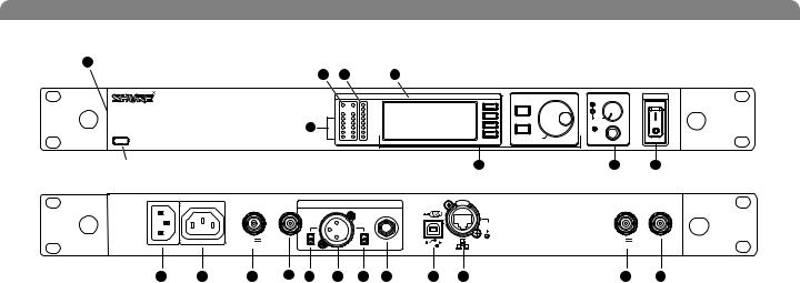
Receiver Controls and Connectors
18 |
|
|
|
17 |
2 |
4 |
5 |
|
|
RF |
Audio |
XX YYY-ZZZ MHz |
Navigate |
Control |
|
|
|
|
|
|
UR4S+ |
OL |
|
|
|
ENTER |
|
|
|
|
||
Wireless Receiver |
3 |
|
|
|
|
with Audio Reference Conpanding |
|
|
|
EXIT |
|
sync |
A |
B |
|
|
push |
|
|
|
Monitor |
POWER |
OFF |
|
push |
|
Monitor Clip |
|
|
|
|
|
|
|
|
|
|
|
6 |
7 |
8 |
|
|
antenna B in |
RF B out |
balanced low Z |
|
receiver outputs |
|
|
networking |
antenna A in |
RF A out |
|
|
|
|
|
200Ω |
|
|
|
|||||
|
|
|
|
|
|
|
|
|
|
|
|
|
|
|
|
|
|
|
|
|
|
|
network |
|
|
|
|
|
|
|
|
|
|
|
|
activity |
|
|
|
|
12.7V out |
|
line |
|
|
lift |
|
|
|
12.7V out |
|
|
|
|
mic |
|
|
GND |
|
|
ethernet |
|
||
|
|
150mA |
|
|
|
|
|
150mA |
|
|||
|
|
|
|
|
|
|
|
|
RJ-45 |
|
||
|
|
|
|
|
|
|
|
|
|
|
|
|
9 |
10 |
11 |
19 |
12 |
13 |
14 |
15 |
16 |
17 |
|
11 |
19 |
SYNC Infrared (IR) port. Transmits group, channel, and other settings to a transmitter. See page 15.
Squelch LEDs.
•Blue (On) = Transmitter signal detected
•Off = no signal or signal squelched because of poor reception or no tonekey
NOTE: The receiver will not output audio unless at least one blue LED is illuminated.
RF LEDs. Indicate RF signal strength from the transmitter at each antenna and diversity condition.
•Amber = normal
•Red = overload (greater than –25 dBm)
4Audio LEDs. Indicate audio signal strength from transmitter.
•Green = signal present
•Yellow = normal peak
•Red = overload
To correct this level, adjust the transmitter gain.
5Indicates the name and range of receiver frequency band.
LCD Interface. Provides a convenient way to program the receiver from the front panel (see detail on next page).
7Monitor. 1/4” output jack and volume knob for headphones.
•Monitor Clip LED indicates headphone audio is clipping.
•Dual models: Push the knob to switch from receiver one to receiver two.
Power switch. Powers the unit on and off.
AC mains power input, IEC connector. 100–240 Vac.
AC mains power passthrough (unswitched). Use IEC extension cables to connect up to five UR4+ receivers to a single AC power source.
Diversity antenna inputs A and B.
Note: Antenna inputs are DC biased. Use only antenna combiners and accessories listed in page 19. Some types of antenna splitters or other products may short the DC power and damage the receiver.
Mic/Line switch. Changes output level 30 dB (XLR output only).
Electrically balanced XLR output jack
Lift/GND switch. Lifts ground from Pin 1 of the XLR connector (default = GND).
Impedance balanced 1/4” output jack (200Ω)
USB jack for computer interface.
RJ-45 jack for Ethernet network interface. Accepts both regular and “ruggedized” RJ-45 plugs.
Temperature-activated fan ensures top performance in high temperature environments. Clean fan screen as needed to remove dust.
The RF distribution ports pass the RF signal from one receiver to the next, allowing a maximum of 10 receivers to share a single pair of antennas.
Note: The diagram above represents the UR4S single channel receiver. The UR4D dual channel receiver is functionally identical to the UR4S, adding a second LCD interface and set of output jacks for channel 2.
8
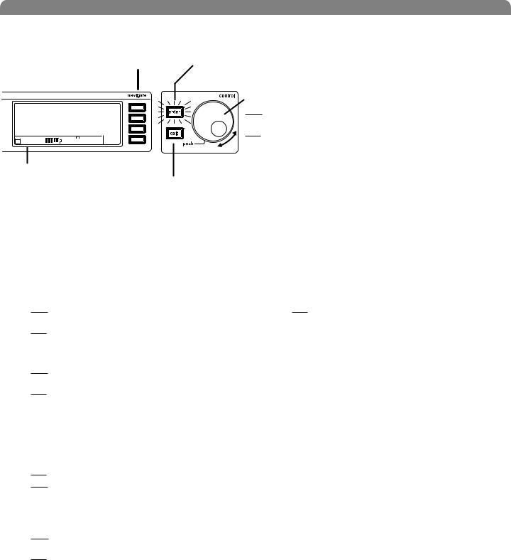
Receiver LCD Interface
Menu Access
Press the Navigate key next to the menu item you want to select.
SHURE |
|
|
|
|
|
|
|
|
|
|
|
|
Radio |
|
524-025 MHz TV: 32 |
|
Audio |
||||||||||||
G: 3 Ch: 1 Out: -0dB |
|
Util |
||||||||||||
|
+12 dB |
|
|
|
|
|
|
|
|
|
|
Hi |
|
F, P, FP Sync |
+ |
|
|
|
|
|
|
|
|
|
|
|
|||
|
|
|
|
|
|
|
|
|
|
|
|
|||
Transmitter Status Display
Everything under the dotted line reflects the settings for the transmitter, if present. (main title screen only).
English
Accept Changes
After changing a parameter, the ENTER button flashes. Press it to save the value.
Cursor Control
Push the Control wheel to move the cursor to the next item.
Turn the Control wheel to change a parameter value.
Exit/Cancel
Press the Exit button to cancel changes and return to the previous menu.
Receiver Parameters
Use the following instructions to set parameters through the LCD interface.
NOTE: After adjusting a parameter, you must press the flashing ENTER button to accept the change.
Group and Channel
Menu: Radio
•Push the Control wheel to move the cursor to the Group (G) or Channel (Ch) parameter.
•Turn the Control wheel to change the parameter.
Frequency
Menu: Radio
•Push the Control wheel to move the cursor to the integer value (524.025 MHz) or fractional value (524.025).
•Turn the Control wheel to change the value.
Automatic Transmitter Sync
Menu: Sync
• See page 15.
Receiver Name
Menu: Util
•Turn the Control wheel to change the letter.
•Push the Control wheel to move to the next letter.
Output Level
Menu: Audio
This setting adjusts the signal level at the XLR and 1/4” audio output jacks.
•Turn the Control wheel to change the relative level in dB. (0 dB to –32 dB).
•Turn the wheel all the way down to mute the outputs.
Squelch
Menu: Radio > Squelch
• Turn the Control wheel to change the parameter
Receiver Lock
When locked, the receiver settings cannot be changed from the front panel. However, you can still navigate the LCD menu to view the settings (and turn the lock off).
Menu: Util > Lock
•Turn the Control wheel to toggle the lock on or off (ON or
OFF).
LCD View
Menu: Util > Title
•Turn the Control wheel to mark an item for display.
•Push the Control wheel to move to the next item.
LCD Contrast
Menu: Util > Contrast
• Turn the Control wheel to increase or decrease contrast.
Tonekey
Menu: Radio > Squelch > Tonekey
Tonekey squelch mutes the outputs unless the receiver detects a transmitter. Tonekey should be left on (On) except for certain troubleshooting operations.
9
Shure UHF-R Wireless
Network Parameters
NOTE:
•The receiver reboots after you press ENTER to accept network parameter changes
•In dual models (UR4D+), these settings affect both receivers (the dual receiver is treated as a single network device).
Set the Receiver Network Mode
Menu: Util > Network
1.Push the Control wheel to move the cursor to the Mode parameter.
2.Turn the Control wheel to set the receiver to one of the following values:
•DHCP: use this setting when connecting the receiver to a DHCP server.
•Manual: allows you to set the receiver to a specific IP address or subnet.
IP Address and Subnet
Menu: Util > Network
NOTE: To change these settings, the network mode must be set to Manual.
1.Push the Control wheel to move the cursor to any of the following parameters:
•IP (IP address)
•Sub (Subnet mask)
2.Turn the Control wheel to change the value.
Device ID
Assists in identifying receivers through the Wireless Workbench Software (has no effect on network identification).
Menu: Util > Network
1.Push the Control wheel to move the cursor to the DevID parameter.
2.Turn the Control wheel to set the receiver to change the value.
Custom Groups This feature allows you to create your own groups of frequencies.
Creating new groups...
Menu: Radio > Custom
3.Turn the Control wheel to select a custom group number (U1, U2, U3, etc.)
4.Push the Control wheel to move to the Channel parameter and turn it to select a channel (01, 02, 03, etc.)
5.Push the Control wheel to move to the Freq parameter and select a frequency for that channel.
6.Push the NEXT menu key to select a frequency for the next channel in that group.
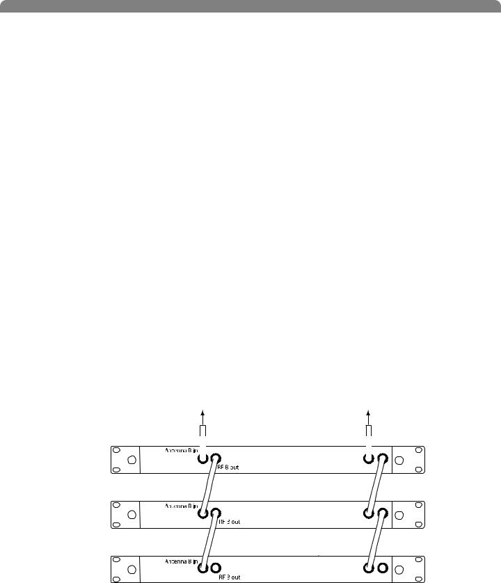
Connecting Multiple Receivers to the RF Distribution Ports
The RF distribution ports pass the RF signal from one receiver to the next, allowing a maximum of 10 single or dual receivers to share a single pair of antennas.
Use the supplied RF distribution cables to connect the ports of each receiver as shown. NOTE: All receivers must be operating in the same frequency band.
To Antenna B |
To Antenna A |
First Receiver |
Antenna A in |
|
RF A out |
||
|
||
Additional Receivers |
Antenna A in |
|
|
||
|
RF A out |
|
Last Receiver |
Antenna A in |
|
RF A out |
||
|
10

English
Automatic Frequency Selection
Follow these steps to use the channel scan and group scan features.
Before you begin...
•Install the receivers in the location where they will be used and power them on.
•Mute all inputs on mixing devices connected to receivers.
•Turn off all bodypack or handheld transmitters for the systems you are setting up.
•Turn on potential sources of interference such as other wireless systems or devices, computers, CD players, effects processors, and digital rack equipment so they are operating as they would be during the presentation or performance.
Single Receiver
1.Select Radio > Scan > Chan Scan using the Navigate keys on the receiver LCD interface.
2.Turn the Control wheel to select a group.
3.Press Chan Scan. The display indicates that the receiver is searching. Once it has finished, it displays the selected channel.
4.Press the flashing ENTER button to accept the suggested channel.
5.Sync the transmitter (see page 15).
Networked or Dual Receivers
With networked or dual receivers, you can take advantage of the group scan feature to set group and channel settings for all the receivers at the same time. (See page 12 for instructions on networking.)
Perform a group scan from any receiver...
1.Select Radio > Scan> Group Scan using the Navigate keys on the receiver LCD interface. The display indicates that the receiver is searching (Scan In Progress). Once it has finished, it displays the group with the most open channels.
2.If you wish, turn the Control wheel to change groups. The number of open channels for each group is displayed.
3.Press the flashing ENTER button to set all receivers to open channels in that group.
NOTE: The group scan feature only works for receivers in the same frequency band. For example, if you did a group scan on a “H4” band receiver, all “H4” band receivers would be set up, but not “J5” band receivers.
Multiple Receivers—Not Networked
If your receivers are not networked (or in different bands), the group scan cannot automatically set their group and channel settings. However, you can still take advantage of the group scan feature to find the group with the most open channels and the channel scan feature to find open channels in that group.
Find the group with the most open channels...
Perform a group scan using the steps for a networked receiver (above). However, make a note of the selected group before pressing the flashing ENTER button to accept it.
Set the receivers to open channels in that group...
Perform a channel scan on the remaining receivers using the steps for a single receiver (above). Make sure to select the same group for each receiver before performing the channel scan.
IMPORTANT: After setting the channel for the first receiver, immediately sync the transmitter for that receiver and leave it on so that the next receiver detects that channel during its channel scan. Otherwise, all the receivers will be set to the same open channel.
NOTE: Receivers in different bands (H4, J5, L3, etc.) do not need to be set to the same group.
11
Shure UHF-R Wireless
Networking Receivers
Basic Network
Connect receivers to an Ethernet router with DHCP service. Use Ethernet switches to extend the network for larger installations.
Use the receiver’s default network setting
(Util > Network > Mode = DHCP).
Accessing the Network with a Computer
If you want to use the Wireless Workbench software, connect your computer to the network and install the software from the CD that came with the receiver. Make sure your computer is configured for DHCP (from Control Panel, click Network Connections. Double-click on Local Area Connection. Select Internet Protocol (TCP/IP) and click Properties. Select Obtain IP address automatically and Obtain DNS server address automatically and click OK).
NOTE: Some security software or firewall settings on your computer can prevent you from connecting to the receivers. If using firewall software, allow connections on port 2201.
Using USB...
Connect the computer to the USB port on any of the receivers to access the whole network.
Computer (optional)
Router with DHCP
|
|
|
|
|
|
|
|
|
|
|
|
|
|
|
|
|
|
|
|
|
|
|
|
|
|
|
|
|
|
|
|
|
|
|
|
|
|
Computer |
|
|
|
|
|
|
|
|
|
|
|
|
|
|
|
|
|
|
|
||
|
|
|
|
|
|
|
|
|
|
|
|
|
|
|
|
|
|
||
Router with DHCP |
|
|
|
||||||||||||||||
|
|
|
(optional) |
||||||||||||||||
|
|
|
|
|
|
|
|
|
|
|
|
|
|
|
|
|
|
||
|
|
|
|
|
|
|
|
|
|
Switch |
|
|
|
|
|
||||
|
|
|
|
|
|
|
|
|
|
|
|
|
|
|
|
|
|
|
|
|
|
|
|
|
|
|
|
|
|
|
|
|
|
|
|
|
|
|
|
|
Ethernet |
|
|
|
|
|
Switch |
USB
Static IP Addressing
The receiver also supports static IP addressing. Assign your own IP addresses ( Util > Network > Mode = Manual). See “Network Parameters” on page 10.
NOTE: Dual receivers use a single IP address, which may be set through either LCD interface.
Existing UHF Network Installations
Both Shure’s UHF-R receivers and legacy UHF receivers can be networked to the same PC and accessed using the latest Wireless Workbench software.
U888 |
RS-232 |
USB |
UHF-R |
|
|
UHF
12
English
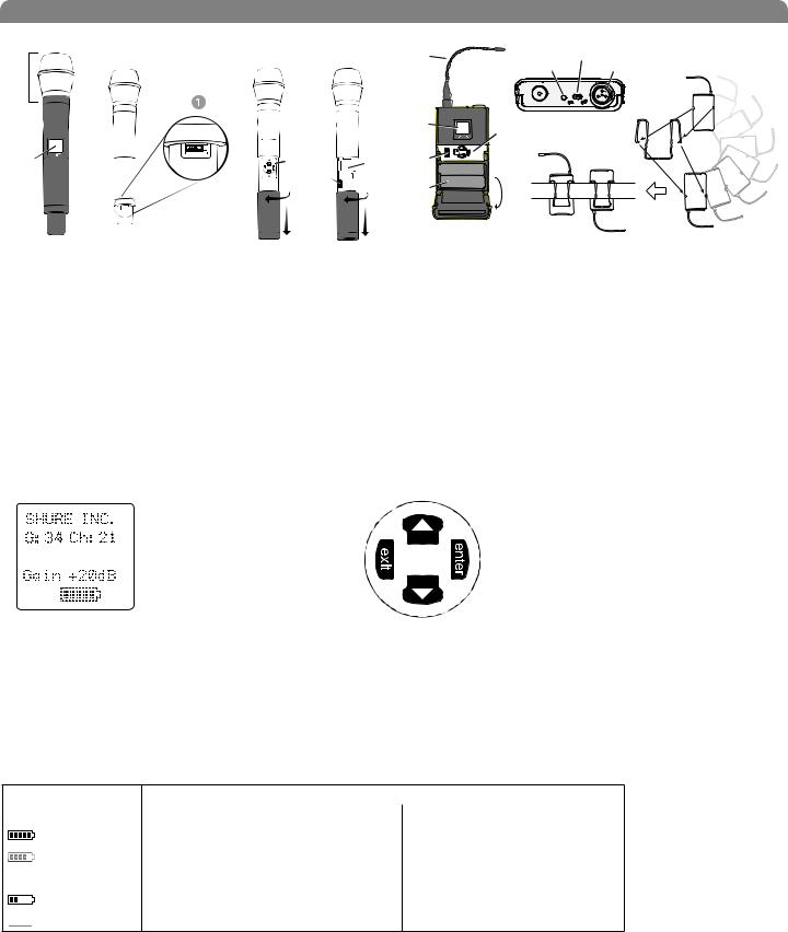
Handheld and Bodypack Transmitter Controls and Connectors
|
|
|
|
|
|
|
|
|
|
|
|
|
|
|
|
|
|
|
|
|
|
|
|
|
|
|
|
|
|
|
|
|
|
|
|
|
|
|
|
|
|
|
|
|
|
|
|
|
|
|
Interchangeable microphone head (BETA 87A pictured). |
Battery compartment. |
||||
LCD Panel. |
Flexible Antenna. |
||||
Power Switch. |
Power LED. |
||||
|
Control buttons for LCD interface. |
|
4-Pin Microphone Input Jack. |
||
|
Infrared (IR) port. See page 15. |
|
Reversible Belt Clip. |
||
Transmitter LCD Interface
524.025 MHz
Main Menu
Up Arrow Key. Scroll up or increase a value.
exit Key. Move to the left, or exit |
enter Key. Press to select parameters |
without saving changes. |
and accept the selected value. |
Down Arrow Key. Scroll down or decrease a value.
Transmitter Batteries
Transmitters operate on standard AA batteries. Turn off the transmitter before changing the batteries.
The battery fuel gauge displayed on the transmitter LCD gives an indication of remaining battery life, as shown below.
UR1, UR2:
Transmitter Display |
Approximate Hours Remaining (alkaline batteries) |
|
|
UR1/UR2 (Normal Power) |
UR1/UR2 (High Power*) |
|
7.5 to 9.5 |
5 to 6 |
|
5.75 to 7.5 |
4 to 5 |
|
|
|
|
4 to 5.75 |
3 to 4 |
|
|
|
|
2 to 4 |
1.5 to 3 |
|
15 minutes to 2 hours |
10 minutes to 1.5 hours |
* High power setting not available with models sold in countries that prohibit its use.
13
 Loading...