


XG-C40XU
XG-C40XU/XE
SERVICE MANUAL
SERVICE-ANLEITUNG
S01B4XG-C40XU
LCD PROJECTOR
LCD PROJEKTOR
MODELS
MODELLE
In the interests of user-safety (Required by safety regulations in some countries) the set should be restored
to its original condition and only parts identical to those specified should be used.
Im lnteresse der Benutzersicherheit (erforderliche Sicherheitsregeln in einigen Ländern) muß das Gerät in seinen
Originalzustand gebracht werden. Außerdem dürfen für die spezifizierten Bauteile nur identische T eile verwendet
werden.
XG-C40XU/XE
CONTENTS INHAL T
Page
» SPECIFICATIONS...................................................... 2
» INPORTANT SERVICE SAFTY NOTES(for USA)...... 3
» OPERATION MANUAL ............................................... 7
» REMOVING OF MAJOR P ARTS.............................. 13
» RESETTING THE TOTAL LAMP TIMER.................. 18
» THE OPTICAL UNIT OUTLINE ................................ 19
» CONVERGENCE AND FOCUS ADJUSTMENT ........ 20
» ELECTRICAL ADJUSTMENT................................... 25
» ADJUSTING THE PC BOARD ................................. 31
» TROUBLE SHOOTING TABLE ................................ 32
» CHASSIS LAYOUT ................................................... 92
» BLOCK DIAGRAM .................................................... 94
» OVERALL WIRING DIAGRAM .................................. 96
» DESCRIPTION OF SCHEMATIC DIAGRAM............. 98
» WAVEFORMS........................................................... 99
» SCHEMATIC DIAGRAM......................................... 100
» PRINTED WIRING BOARD ASSEMBLIES ............ 148
» PARTS LIST
Ë
ELECTRICAL PARTS ........................................ 158
Ë
CABINET AND MECHANICAL PARTS .............. 178
Ë
ACCESSORIES PARTS .................................... 184
Ë
PACKING PARTS............................................... 184
» PACKING OF THE SET.......................................... 185
» TECHNISCHE DATEN ............................................. 48
» HINWEISE FÜR DAS WARTUNGSPERSONAL...... 49
» BEDIENUNGSANLEITUNG ..................................... 50
» ENTFERNEN DER HAUPTTEILE............................ 56
» NULLSTELLUNG DES LAMPEN-
BETRIEBSSTUNDENZÄHLERS (GESAMTZEIT).... 61
» ÜBERSICHT DER OPTIKEINHEIT .......................... 62
» EINSTELLUNG VON KONVERGENZ UND
BRENNPUNKT ......................................................... 63
» ELEKTRISCHE EINSTELLUNG............................... 68
» EINSTELLUNG DER PC-PLATINE .......................... 74
» FEHLERSUCHTABELLE.......................................... 75
» CHASSIS-ANORDNUNG ......................................... 92
» BLOCKSCHALTBILD................................................ 94
» GESAMTSCHALTPLAN ........................................... 96
» BESCHREIBUNG DES SCHEMATISCHEN
SCHALTPLANS ........................................................ 98
» WELLENFORMEN ................................................... 99
» SCHEMATISCHER SCHALTPLAN ........................ 100
» LEITERPLATTENEINHEITEN ................................ 148
» ERSATZTEILLISTE
Ë
ELEKTRISCHE BAUTEILE................................ 158
Ë
GEHÄUSE UND MECHANISCHE BAUTEILE... 178
Ë
ZUBEHÖRTEILE................................................ 184
Ë
VERPACKUNGSTEILE...................................... 184
» VERPACKEN DES GERÄTS.................................. 185
Seite
SHARP CORPORATION
1

XG-C40XU/XE
Specifications
Product type
Video system
Display method
LCD panel
LCD Projector
Model
XG-C40XU/XE
PAL/SECAM/NTSC 3.58/NTSC 4.43/DTV 480P/DTV 720P/DTV 1080I
LCD panel × 3, RGB optical shutter method
Panel size: 22.9 mm (0.9") (13.9 [H] × 18.5 [W] mm)
Display method: Translucent TN liquid crystal panel
Drive method: TFT (Thin Film Transistor) Active Matrix panel
No. of dots: 786,432 dots (1,024 [H] × 768 [V])
Lens
Projection lamp
Contrast ratio
Video input signal
1–1.3 × zoom lens, F1.7–2.0, f = 33–43 mm
DC 200 W lamp
250:1
RCA Connector: VIDEO, composite video, 1.0 Vp-p, sync negative, 75 Ω terminated
RCA Connector: AUDIO, 0.5 Vrms more than 22 kΩ (stereo)
S-video input signal
4-pin Mini DIN connector
Y (luminance signal): 1.0 Vp-p, sync negative, 75 Ω terminated
C (chrominance signal): Burst 0.286 Vp-p, 75 Ω terminated
Horizontal resolution
Audio output
Computer RGB input signal
560 TV lines (video input), 750 TV lines (DTV 720P input, Dot by Dot)
3 W (monaural)
PIN MINI
D-
15-
SUB CONNECTOR
RGB separate/composite sync/sync on green type analog input: 0–0.7 Vp-p, positive,
75 Ω terminated
Pixel clock
Vertical frequency
Horizontal frequency
Computer control signal
Speaker system
Rated voltage
Input current
Rated frequency
Power consumption
Operating temperature
Storage temperature
Cabinet
I/R carrier frequency
Laser pointer of remote control
Dimensions (approx.)
TEREO MINIJACK
S
ORIZONTAL SYNC. SIGNAL
H
ERTICAL SYNC. SIGNAL
V
12–230 MHz
43–200 Hz
15–126 kHz
9-pin Mini DIN female connector (RS-232C Input Port)
8 cm (3
AC 100–240 V
3.3 A
50/60 Hz
300 W
41°F to + 104°F (+ 5°C to + 40°C)
-4°F to + 140°F (– 20°C to + 60°C)
Plastic
38 kHz
Wave length: 650 nm / Max. output: 1 mW / Class II Laser Product
1
/64" (W) × 4 49/64" (H) × 12 13/64" (D) (229 × 121 × 310 mm) (main body only)
9
19
/32" (W) × 5 9/32" (H) × 14 7/64" (D) (243.5 × 134 × 358.4 mm) (including adjustment feet
9
: AUDIO, 0.5 Vrms, more than 22 kΩ (stereo)
: TTL level (positive/negative) or composite sync (Apple only)
: Same as above
3
⁄32") round
and projecting parts)
Weight (approx.)
Supplied accessories
10.6 lbs. (4.8 kg)
Remote control, Two AA size batteries, Power cord (11' 10" 3.6m), Computer RGB cable
(9' 10" 3 m), Computer audio cable (9' 10" 3 m), USB mouse control cable (3' 3" 1 m),
DIN-D-sub RS-232C cable (6
(attached), CD-ROM, LCD projector operation manual, LCD projector quick references,
Sharp Advanced Presentation Software operation manual
Replacement parts
Lamp unit (Lamp/cage module) (BQC-XGC40XU/1), Remote control (RRMCG1579CESA),
(RRMCG1584CESA),AA size batteries, Power cord (QACCU5013CEZZ(XG-C40XU),
QACCB5024CENA(XG-C40XE),QACCV4002CEZZ(XG-C40XE)), Computer RGB cable
(QCNWG0002CEZZ), Computer audio cable (QCNW-4870CEZZ), USB mouse control
cable (QCNWG0007CEPZ), DIN-D-sub RS-232C cable (QCNW-5288CEZZ), Remote mouse
receiver (RUNTK0673CEZZ), Air filter (PFILD0076CEZZ), Lens cap (GCOVH1307CESB),
CD-ROM (UDSKA0053CEN1),(UDSKA0057CEN1), LCD projector operation manual
(TINS-7482CEZZ),(TINS-7533CEZZ), LCD projector quick references (TINS-7483CEZZ),
(TINS-7534CEZZ, TINS-7535CEZZ, TINS-7536CEZZ), Sharp Advanced Presentation
Software operation manual (TINS-7538CEZZ),(TINS-7537CEZZ)
This SHARP projector uses LCD (Liquid Crystal Display) panels. These
very sophisticated panels contain 786,432 pixels (
Film Transistors). As with any high technology electronic equipment
such as large screen TVs, video systems and video cameras, there
are certain acceptable tolerances that the equipment must conform
to.
×
RGB) TFTs (Thin
(INPUT 1, 2):
45
/64" 15 cm), Remote mouse receiver, Extra air filter, Lens cap
This unit has some inactive TFTs within acceptable tolerances which
may result in illuminated or inactive dots on the picture screen. This
will not affect the picture quality or the life expectancy of the unit.
Specifications are subject to change without notice.
2
XG-C40XU/XE
12345678901234567890123456789012123456789012345678901234567890121234567890123456789012345678901212
1
2
12345678901234567890123456789012123456789012345678901234567890121234567890123456789012345678901212
12345678901234567890123456789012123456789012345678901234567890121234567890123456789012345678901212
2
12345678901234567890123456789012123456789012345678901234567890121234567890123456789012345678901212
INPORTANT SERVICE SAFETY NOTES (for USA)
Ë Service work should be performed only by qualified service technicians who are
thoroughly familiar with all safety checks and servicing guidelines as follows:
WARNING
1. For continued safety, no modification of any circuit
should be attempted.
2. Disconnect AC power before servicing.
BEFORE RETURNING THE PROJECTOR:
(Fire & Shock Hazard)
Before returning the projector to the user, perform
the following safety checks:
1. Inspect lead wires are not pinched between the
chassis and other metal parts of the projector.
2. Inspect all protective devices such as non-metallic
control knobs, insulating materials, cabinet backs,
adjustment and compartment covers or shields,
isolation resistor-capacity networks, mechanical
insulators, etc.
3. To be sure that no shock hazard exists, check for
current leakage in the following manner:
» Plug the AC cord directly into a 120-volt AC outlet,
(Do not use an isolation transformer for this test).
» Using two clip leads, connect a 1.5k ohm, 10 watt
resistor paralleled by a 0.15µF capacitor in parallel
between all exposed metal cabinet parts and earth
ground.
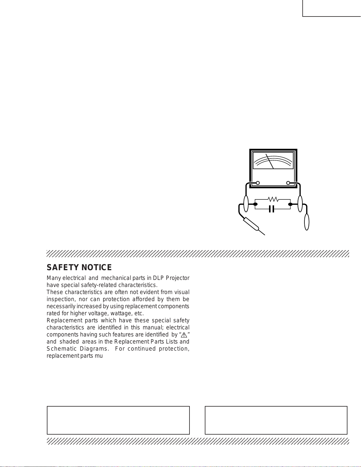
» Use an AC voltmeter with sensitivity of 5000 ohm per
volt., or higher, sensitivity to measure the AC voltage
drop across the resistor (See Diagram).
» All checks must be repeated with the AC plug
connection reversed. (If necessary , a non-polarized
adapter plug must be used only for the purpose of
completing these checks.)
Any reading of 0.3 volts RMS (this corresponds to
0.2 milliamp. AC.) or more is excessive and indicates
a potential shock hazard which must be corrected
before returning the unit to the owner.
AC
VOLTMETER
1.5k ohm (10W)
0.15µF
TEST PROBE
TO EXPOSED
METAL PARTS
CONNECT TO KNOWN
EARTH GROUND
1234567890123456789012345678901212345678901234567890123456789012123456789012345678901234567890121
SAFETY NOTICE
Many electrical and mechanical parts in DLP Projector
have special safety-related characteristics.
These characteristics are often not evident from visual
inspection, nor can protection afforded by them be
necessarily increased by using replacement components
rated for higher voltage, wattage, etc.
Replacement parts which have these special safety
characteristics are identified in this manual; electrical
components having such features are identified by “å”
and shaded areas in the Replacement Parts Lists and
Schematic Diagrams. For continued protection,
replacement parts must be identical to those used in the
original circuit. The use of a substitute replacement parts
which do not have the same safety characteristics as
the factory recommended replacement parts shown in
this service manual, may create shock, fire or other
hazards.
AVIS POUR LA SECURITE
De nombreuses pièces, électriques et mécaniques, dans
les projecteur à DLP présentent des caractéristiques
spéciales relatives à la sécurité, qui ne sont souvent
pas évidentes à vue.
Le degré de protection ne peut pas être nécessairement
augmentée en utilisant des pièces de remplacement
étalonnées pour haute tension, puissance, etc.
Les pièces de remplacement qui présentent ces
caractéristiques sont identifiées dans ce manuel;
les pièces électriques qui présentent ces particularités
sont identifiées par la marque “å” et hachurées dans la
liste des pièces de remplacement et les diagrammes
schématiques. Pour assurer la protection, ces pièces
doivent être identiques à celles utilisées dans le circuit
d’origine. L’utilisation de pièces qui n’ont pas les mêmes
caractéristiques que les pièces recommandées par
l’usine, indiquées dans ce manuel, peut provoquer des
électrocutions, incendies ou autres accidents.
WARNING: The bimetallic component has the primary
conductive side exposed. Be very careful in
handling this component when the power is on.
234567890123456789012345678901212345678901234567890123456789012123456789012345678901234567890121
AVERTISSEMENT: La composante bimétallique dispose du
conducteur primaire dénudé. Faire
attention lors de la manipulation de cette
composante sous tension.
3
XG-C40XU/XE
5
5
NOTE TO SERVICE
PERSONNEL
234567890123456789012345678901212345678901234
UV-RADIATION PRECAUTION
The light source, metal halide lamp, in the LCD
projector emits small amounts of UV-Radiation.
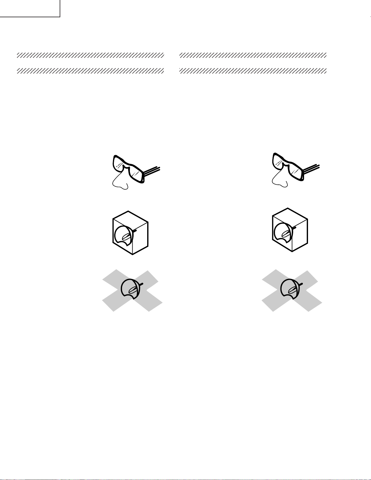
A VOID DIRECT EYE AND SKIN EXPOSURE.
To ensure safety please adhere to the following:
1. Be sure to wear sun-glasses when servicing the
projector with the lamp
turned “on” and the top
enclosure removed.
2. Do not operate the lamp outside of the lamp housing.
NOTE POUR LE PERSONNEL
D’ENTRETIEN
234567890123456789012345678901212345678901234
PRECAUTION POUR LES RADIATIONS UV
La source de lumière, la lampe mètal halide , dans le
projecteur LCD émet de petites quantités de
radiation UV.
EVITEZ TOUTE EXPOSITION DIRECTE
DES YEUX ET DE LA PEAU.
Pour votre sécurité, nous vous prions de respecter
les points suivants:
1. Toujours porter des lunettes de soleil lors d’un
entretien du projecteur
avec la lampe allumée
et le haut du coffret retiré.
2. Ne pas faire fonctionner la lampe à l’extérieur du
boîtier de lampe.
3. Do not operate for more than 2 hours with the
enclosure removed.
UV-Radiation and Medium Pressure
Lamp Precautions
1. Be sure to disconnect the AC plug when replacing
the lamp.
2. Allow one hour for the unit to cool down before
servicing.
3. Replace only with same type lamp. Type
CLMPF0075CE01 or BQC-XGC40XU/1 rated 85V/
200W.
4. The lamp emits small amounts of UV-Radiation, avoid
direct-eye contact.
5. The medium pressure lamp involves a risk of
explosion. Be sure to follow installation instructions
described below and handle the lamp with care.
3. Ne pas faire fonctionner plus de 2 heures avec le
coffret retiré.
Précautions pour les radiations UV
et la lampe moyenne pression
1. Toujours débrancher la fiche AC lors du
remplacement de la lampe.
2. Laisser l’unité refroidir pendant une heure avant de
procéder à l’entretien.
3. Ne remplacer qu’avec une lampe du même type.
Type CLMPF0075CE01 or BQC-XGC40XU/1,
caractéristique 85V/200W.
4. La lampe émet de petites quantités de radiation UV éviter tout contact direct avec les yeux.
5. La lampe moyenne pression implique un risque
d’explosion. Toujours suivre les instructions
d’installation décrites ci-dessous et manipuler la
lampe avec soin.
4
XG-C40XU/XE
4
5
SHARP
UV-RADIATION PRECAUTION (Continued)
23456789012345678901234567890121234567890123
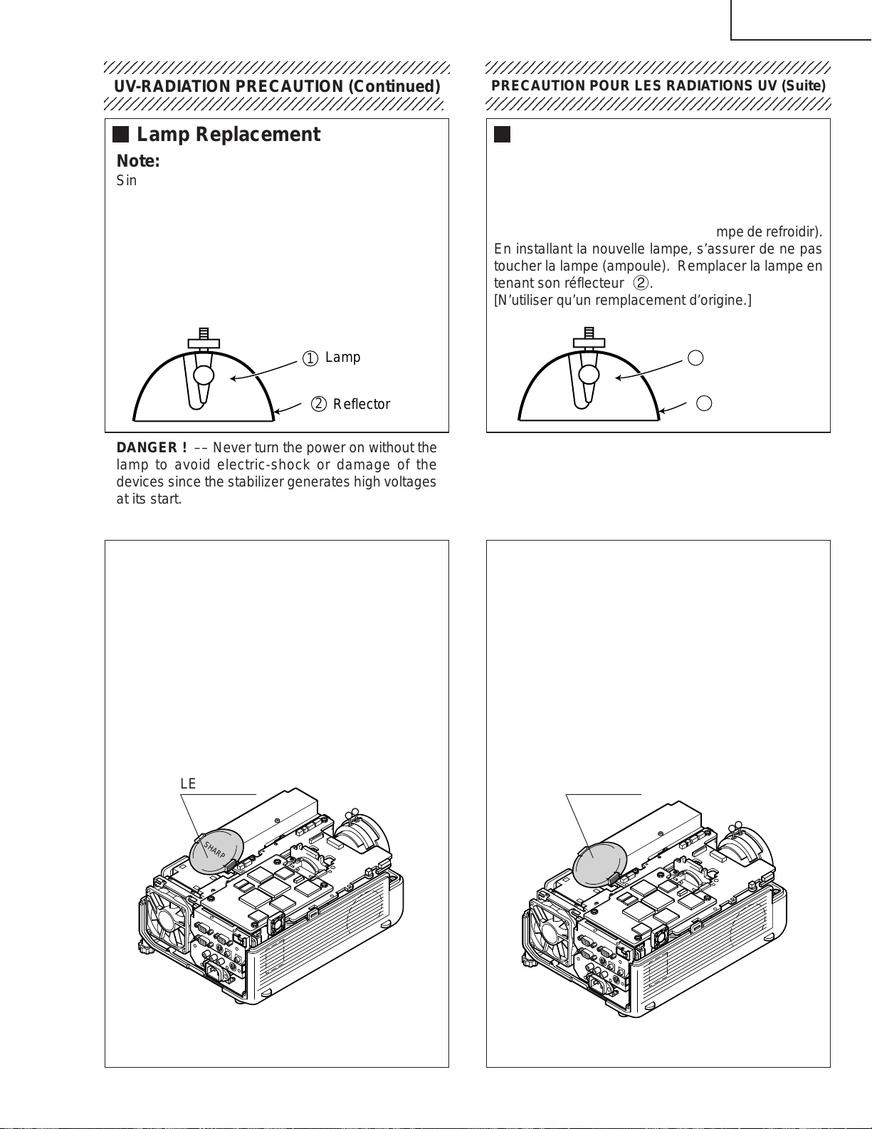
Lamp Replacement
Note:
Since the lamp reaches a very high temperature
during units operation replacement of the lamp
should be done at least one hour after the power
has been turned off. (to allow the lamp to cool off.)
Installing the new lamp, make sure not to touch the
lamp (bulb) replace the lamp by holding its reflector
2.
[Use original replacement only.]
Lamp
1
2
Reflector
DANGER ! –– Never turn the power on without the
lamp to avoid electric-shock or damage of the
devices since the stabilizer generates high voltages
at its start.
PRECAUTION POUR LES RADIATIONS UV (Suite)
234567890123456789012345678901212345678901234
Remplacement de la lampe
Remarque:
Comme la lampe devient très chaude pendant le
fonctionnement de l’unité, son remplacement ne doit
être effectué au moins une heure après avoir coupé
l’alimentation (pour permettre à la lampe de refroidir).
En installant la nouvelle lampe, s’assurer de ne pas
toucher la lampe (ampoule). Remplacer la lampe en
tenant son réflecteur 2.
[N’utiliser qu’un remplacement d’origine.]
Lamp
1
2
Reflector
DANGER ! –– Ne jamais mettre sous tension sans
la lampe pour éviter un choc électrique ou des
dommages des appareils car le stabilisateur génère
de hautes tensions à sa mise en route.
Since small amounts of UV-Radiation are emitted
from an opening between the duct cover and the
lamp housing, it is recommended to place the LENS
CAP on the opening during servicing to avoid eye
and skin exposure (Fig. 1).
Note: Please obtain a lens cap before servicing a
model XG-C40XU that is received without
one.
LENS CAP
SHARP
Comme de petites quantités de radiation UV sont
émises par une ouverture entre le couvercle du conduit et le botier de la lampe,il est recommandé de
placer le CAPUCHON D'OPTIQUE sur l'ouverture
pendant l'entretien pour éviter une exposition des
yeux et la peau (Fig. 1).
Remarque: Priére de se procurer un capuchon
d'optique acant d'entretien un modéle
XG-C40XU qui est livré sans.
LENS CAP
Figure 1.
Figure 1.
5
XG-C40XU/XE
WARNING: High brightness light source, do not stare into the beam of light, or view directly . Be especially
careful that children do not stare directly in to the beam of light.
WARNING: TO REDUCE THE RISK OF FIRE OR ELECTRIC SHOCK, DO NOT EXPOSE THIS UNIT TO
MOISTURE OR WET LOCATIONS.
CAUTION
RISK OF ELECTRIC SHOCK.
DO NOT REMOVE SCREWS
EXCEPT SPECIFIED USER
SERVICE SCREW
CAUTION: TO REDUCE THE RISK OF ELECTRIC SHOCK,
DO NOT REMOVE CABINET.
NO USER-SERVICEABLE P ARTS EXCEPT LAMP UNIT.
REFER SERVICING TO QUALIFIED SERVICE
PERSONNEL.
The lighting flash with arrowhead within a
triangle is intended to tell the user that
parts inside the product are risk of electric
shock to persons.
The exclamation point within a triangle is
intended to tell the user that important
operating and servicing instructions are in
the manual with the projector.
CAUTION
(INLET Unit)
For continued protection
against a risk of fire,
replace only with same
5A 250V
A VERTISSEMENT : Source lumineuse de grande intensité. Ne pas fixer le faisceau lumineux ou le regarder
type 5A 250V fuse.
(F761)
directement. Veiller particulièrement à éviter que les enfants ne fixent directement le
faisceau lumineux.
A VERTISSEMENT : AFIN D’EVITER TOUT RISQUE D’INCENDIE OU D’ELECTROCUTION, NE P AS PLACER
CET APPAREIL DANS UN ENDROIT HUMIDE OU MOUILLE.
ATTENTION
RISQUE
D’ELECTROCUTION NE
PASRETIRER LES VIS, A
L’EXCEPTION DES VIS DE
REPARATION UTILISATEUR
SPECIFIEES
L’éclair terminé d’une flèche à l’intérieur
d’un triangle indique à l’utilisateur que les
pi‘eces se trouvant dans l’appareil sont
susceptibles de provoquer une décharge
électrique.
Le point d’exclamation à l’intérieur d’un
ATTENTION: POUR EVITER TOUT RISQUE
D’ELECTROCUTION, NE PAS RETIRER LE CAPOT.
AUCUNE DES PIECES INTERIEURES N’EST REP ARABLE
PAR L’UTILISATEUR, A L’EXCEPTION DE L’UNITE DE
LAMPE. POUR TOUTE REPARATION, S’ADRESSER A UN
TECHNICIEN D’ENTRETIEN QUALIFIE.
triangle indique à l’utilisateur que les
instructions de fonctionnement et
d’entretien sont détaillées dans les
documents fournis avec le projecteur.
PRECAUTION
(Unite d’admission)
Pour une protection continue
contre les risques d’incendie,
ne remplacer qu’avec un
5A 250V
fusible 5A 250V du même
type.
(F761)
6
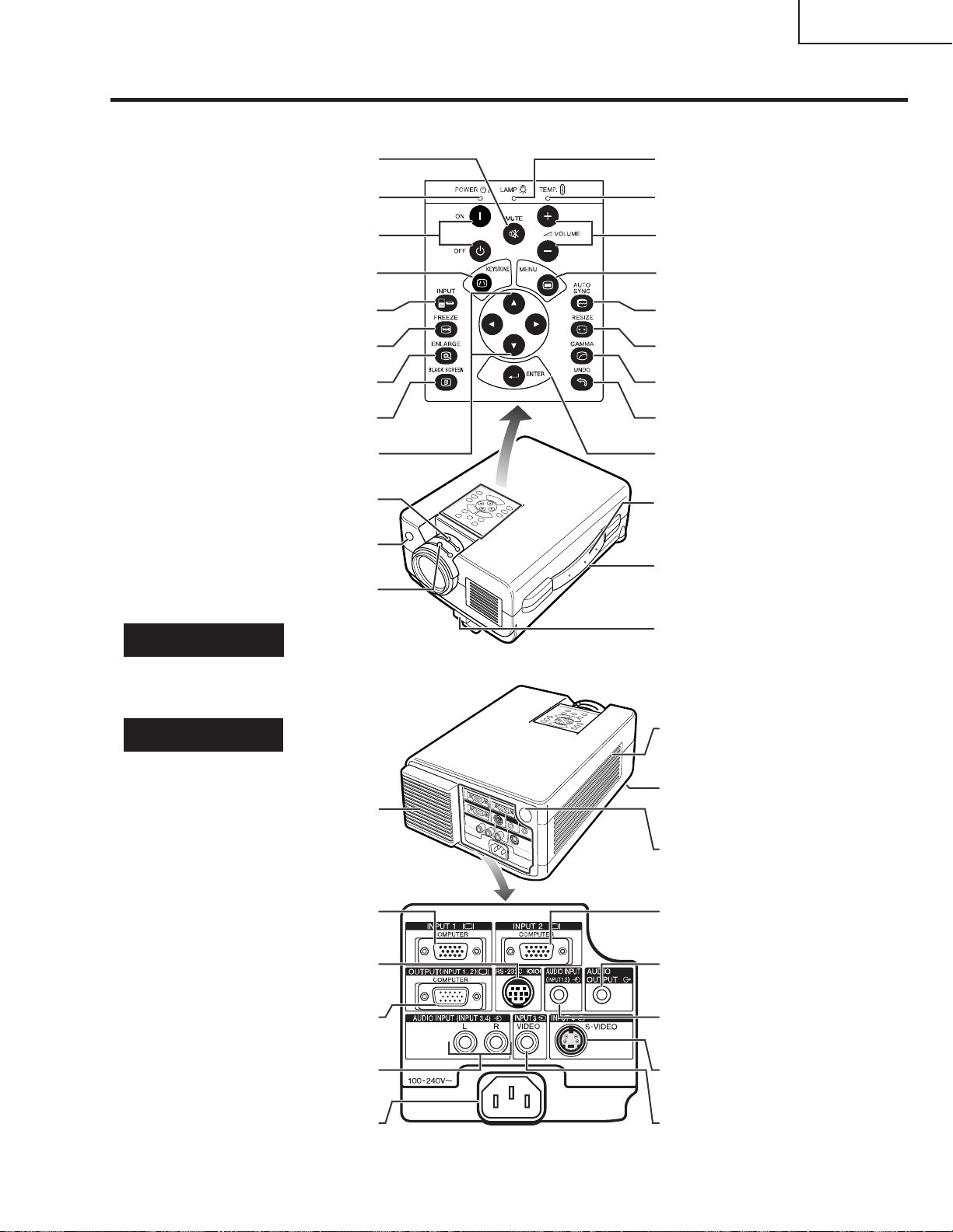
Location of Controls
Projector
Foot release
VOLUME buttons (+ / – )
MENU button
ENTER button
UNDO button
GAMMA button
RESIZE button
AUTO SYNC button
MUTE button
KEYSTONE button
BLACK SCREEN button
ENLARGE button
FREEZE button
INPUT button
POWER buttons (ON/OFF)
POWER indicator
ADJUSTMENT buttons
TEMPERATURE WARNING
indicator
LAMP REPLACEMENT
indicator
Carrying handle
Zoom knob
Remote control sensor
Kensington Security Standard
connector
Front and Top View
Side and RearView
INPUT 1 port (HD 15)
Cooling fan (Exhaust vent)
RS-232C port (9-pin Mini DIN)
AUDIO INPUT 3 terminals (RCA)
OUTPUT port for INPUT 1, 2 (HD 15)
Speaker
AC socket
INPUT 2 port (HD 15)
AUDIO OUTPUT terminal
(3.5mm stereo minijack)
AUDIO INPUT terminal
for INPUT 1, 2
(3.5 mm stereo minijack)
S-VIDEO INPUT 4 terminal
(4-pin Mini DIN)
VIDEO INPUT 3 terminal
(RCA)
Focus knob
Air filter/Cooling fan (Intake vent)
Remote control sensor
('/"/\/|)
OPERATION MANUAL
XG-C40XU/XE
7
XG-C40XU/XE
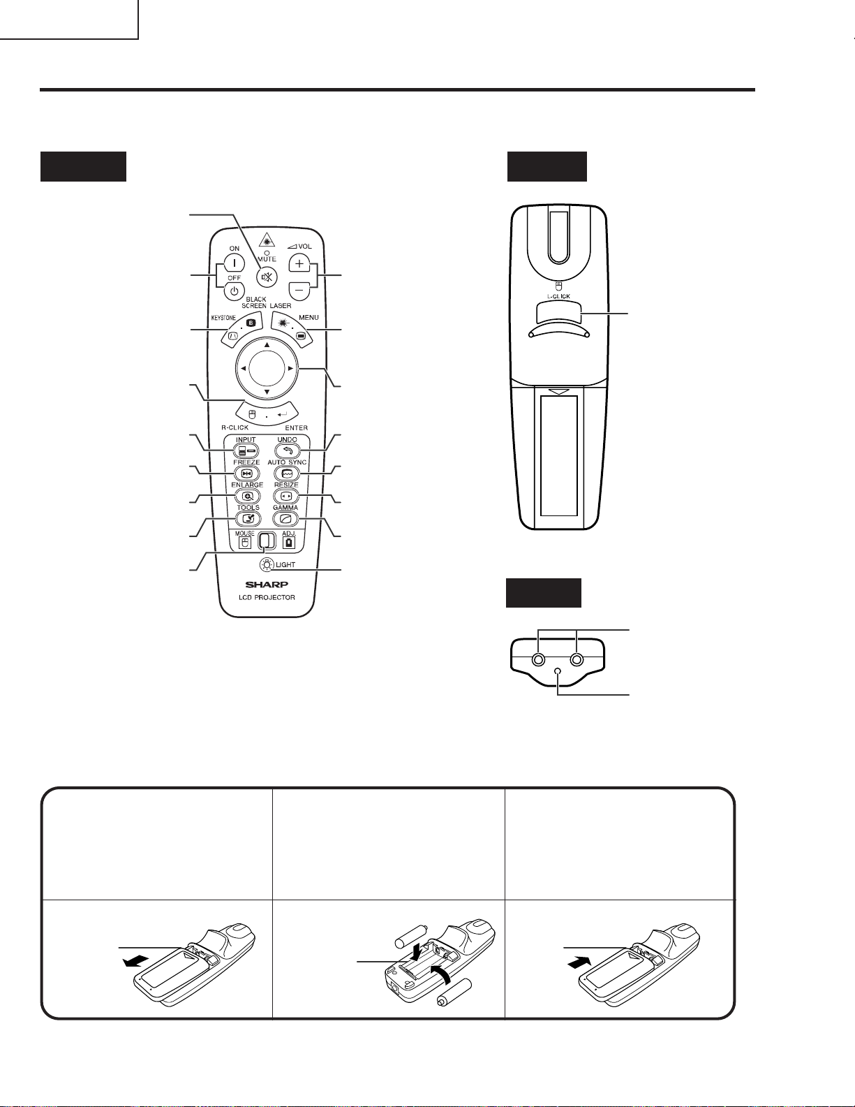
Operating the Wireless Mouse Remote Control
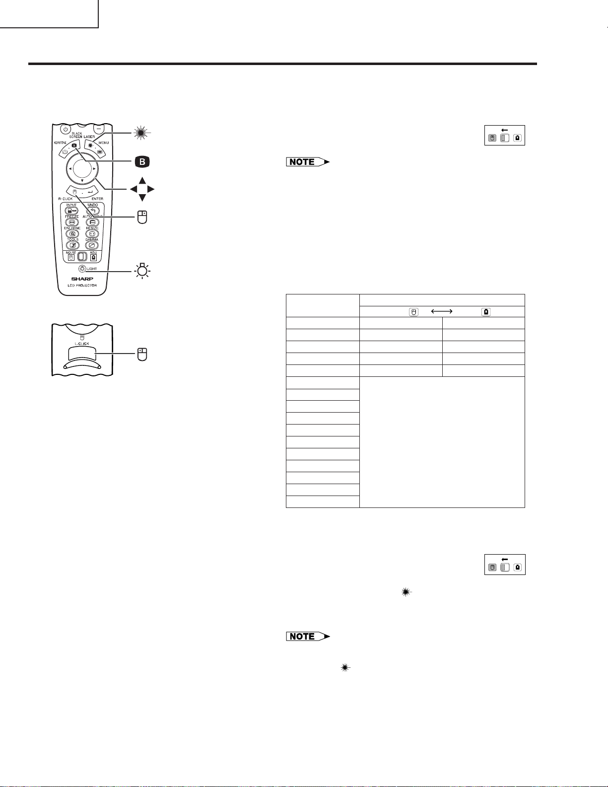
Remote Control
Front View Rear View
MUTE button
POWER buttons
(ON/OFF)
KEYSTONE/BLACK
SCREEN button
RIGHT-CLICK/
ENTER button
INPUT button
FREEZE button
ENLARGE button
TOOLS button
MOUSE/
ADJUSTMENT
switch
VOLUME buttons
( + / – )
LASER POINTER/
MENU button
MOUSE/
ADJUSTMENT
buttons ('/"/\/|)
UNDO button
AUTO SYNC button
RESIZE button
GAMMA button
BACKLIGHT button
LEFT-CLICK
button
Top View
Remote control
signal transmitter
Inserting the batteries
Press in on the arrow
1
mark and slide in the
direction of the arrow to
remove the battery cover.
Battery
cover
Insert two AA size
2
batteries, making sure
their polarities match the
+ and – marks inside
the battery compartment.
Battery
compartment
8
Laser
pointer
window
Insert the side tabs of
3
the battery cover into
their slots and press the
cover in until it is
properly seated.
Battery
cover
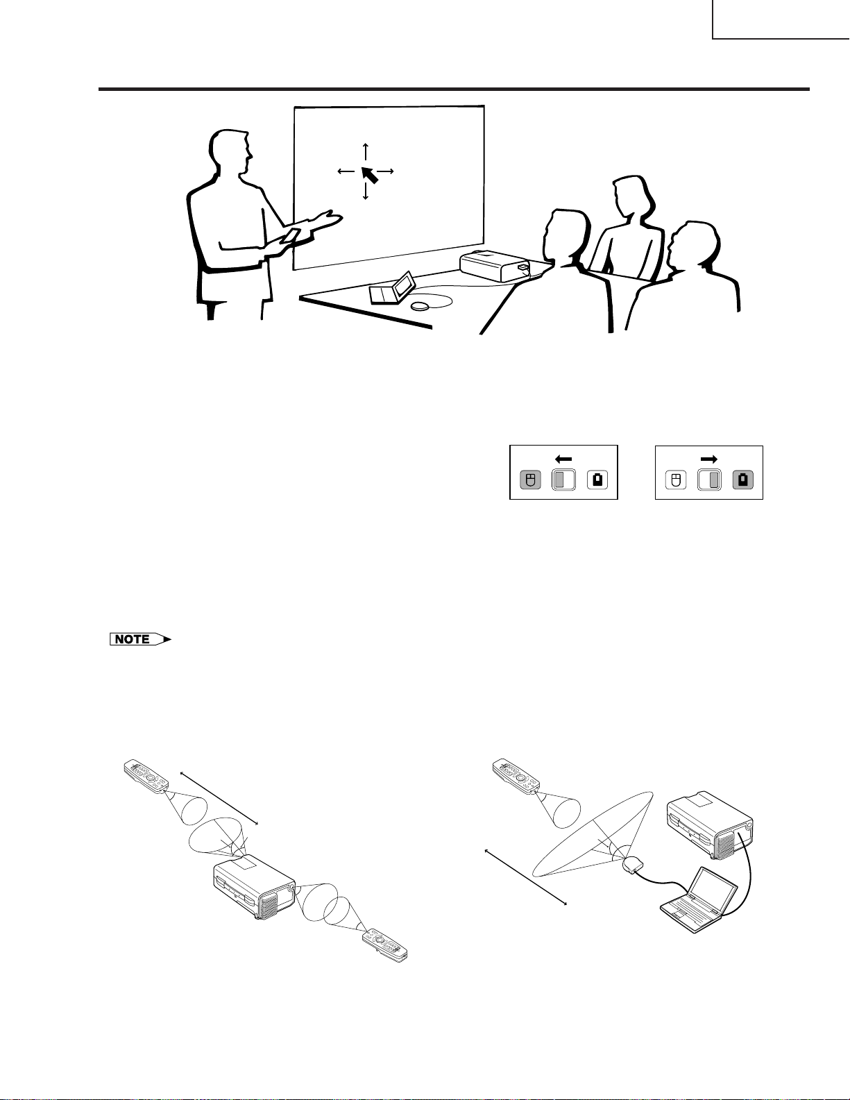
Using the Remote Control as a Wireless Mouse
XG-C40XU/XE
The remote control has the following three functions:
• Projector control
MOUSE/ADJUSTMENT switch
(Remote control)
• Wireless mouse
• Laser pointer
MOUSE
ADJ.
Wireless mouse
Laser pointer
MOUSE
ADJ.
Projector control
Remote Control/Mouse Receiver Positioning
• The remote control can be used to control the projector within the ranges shown below.
• The remote mouse receiver can be used with the remote control to control the mouse functions of a connected
computer within the ranges shown below.
• The signal from the remote control can be reflected off a screen for easy operation. However, the effective distance of the
signal may differ due to the screen material.
Controlling the Projector
Remote control
7 m
30˚
Using the Wireless Mouse
Remote control
30˚
45˚
30˚
4 m
45˚
30˚
Remote control
30˚
Remote
mouse
receiver
120˚
9
XG-C40XU/XE
Effective buttons in MOUSE mode
Remote control
(Front view)
LASER POINTER
BLACK SCREEN
MOUSE
RIGHT-CLICK
BACKLIGHT
Remote control
(Rear view)
LEFT-CLICK
Use as a Wireless Mouse
Be sure the supplied remote mouse receiver is
connected to your computer.
(Slide the MOUSE/ADJUSTMENT switch on
the remote control to the MOUSE position.)
• The wireless mouse may not operate correctly if your
computer serial port is not correctly set up. Refer to the
computer’s operation manual for details of setting up/
installing the mouse driver.
• For one-button mouse systems, use either the LEFT-CLICK
or RIGHT-CLICK button.
Using the remote control in a dark room
Press BACKLIGHT, and the buttons will light up. Green
lights refer to mouse operations, and red lights to
projector adjustments.
Button name
LASER POINTER/MENU
BLACK SCREEN/KEYSTONE
RIGHT-CLICK/ENTER
MOUSE/ADJUSTMENT
LEFT-CLICK
POWER ON/OFF
VOLUME + / –
MUTE
INPUT
UNDO
FREEZE
AUTO SYNC
ENLARGE
RESIZE
TOOLS
GAMMA
Position of MOUSE/ADJUSTMENT switch
MOUSE
LASER POINTER (GREEN)
BLACK SCREEN (GREEN)
RIGHT-CLICK (GREEN)
MOUSE (NOT LIT)
ON (NOT LIT)
MENU (RED)
KEYSTONE
ENTER (RED)
ADJUSTMENT (NOT LIT)
ON (RED)
ADJ.
MOUSE
(RED)
—
ADJ.
Use as a Laser Pointer
(Slide the MOUSE/ADJUSTMENT switch on
the remote control to the MOUSE position.)
Press LASER POINTER ( ) to activate the laser
pointer. When the button is released, the light
automatically goes off.
• For safety, the laser pointer automatically goes off after 1
minute of continuous use. To turn it on, release LASER
POINTER ( ) and press again.
10
MOUSE
ADJ.
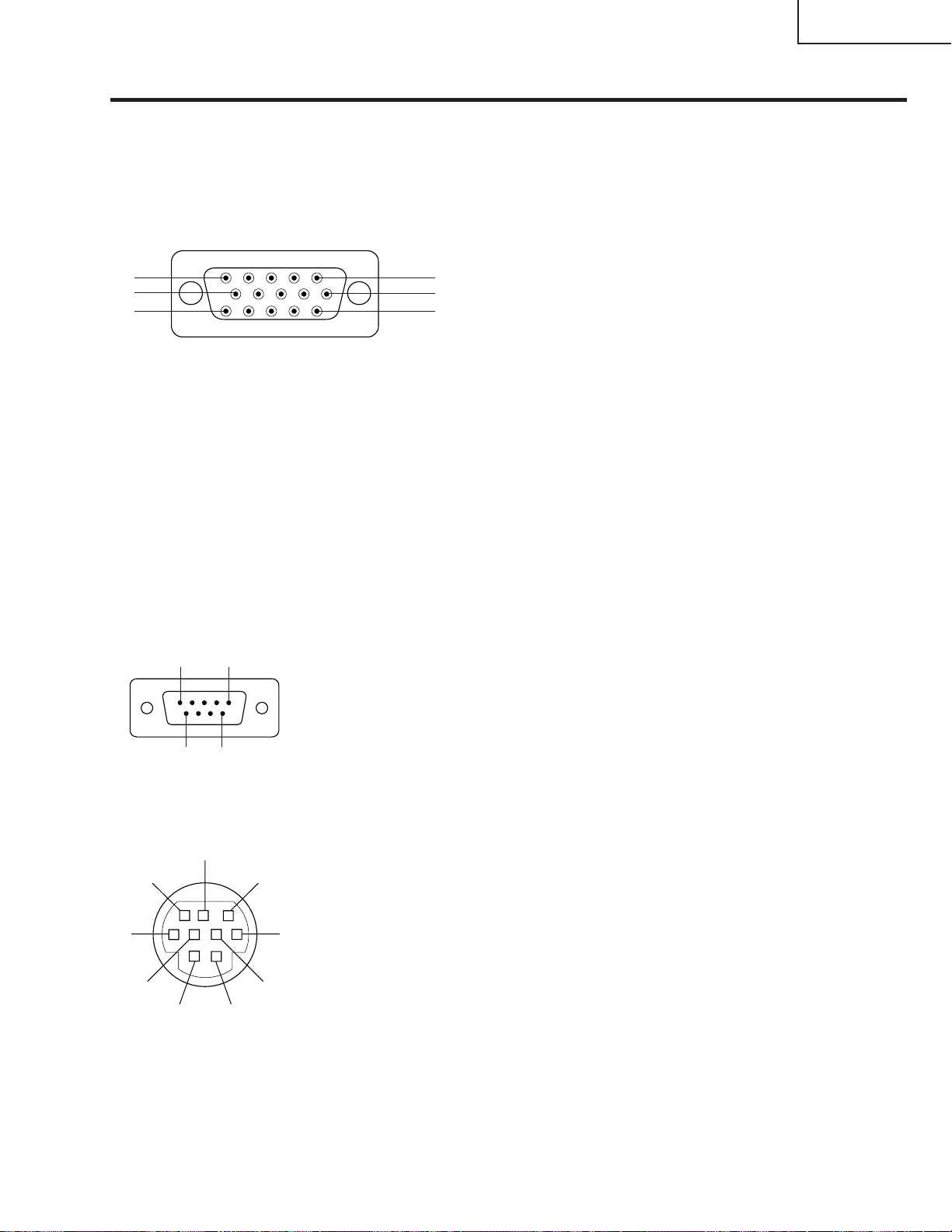
Connection Pin Assignments
Analog Computer 1 and 2 Signal Input Ports: 15-pin mini D-sub female connector
Computer Input
Analog
10
15
1. Video input (red)
2. Video input
(green/sync on green)
5
1
6
11
3. Video input (blue)
4. Reserve input 1
5. Composite sync
6. Earth (red)
7. Earth (green/sync on green)
8. Earth (blue)
Component Input
R
(CR)
1. P
2. Y
B
3. P
4. Not connected
5. Not connected
R
6. Earth (P
7. Earth (Y)
8. Earth (P
)
B
)
9. Not connected
10. GND
11. GND
12. Bi-directional data
13. Horizontal sync signal
14. Vertical sync signal
15. Data clock
9. Not connected
10. Not connected
11. Not connected
12. Not connected
13. Not connected
14. Not connected
15. Not connected
XG-C40XU/XE
RS-232C Port: 9-pin D-sub male connector of the DIN-D-sub RS-232C cable
Pin No. Signal Name I/O Reference
1
5
9
6
1 CD Not connected
2 RD Receive Data Input Connected to internal circuit
3 SD Send Data Output Connected to internal circuit
4 ER Not connected
5 SG Signal Ground Connected to internal circuit
6 DR Data Set Ready Output Not connected
7 RS Request to Send Output Connected to internal circuit
8 CS Clear to Send Input Connected to internal circuit
9 CI Not connected
RS-232C Terminal: 9-pin Mini DIN female connector
8
9
7
6
5
2
4
1
Pin No. Signal Name I/O Reference
1 VCC + 3.3V (Reserved) Output Not connected
2 RD Receive Data Input Connected to internal circuit
3 SD Send Data Output Connected to internal circuit
4 EXIR Detector of Option Unit Input Not connected
3
5 SG Signal Ground Connected to internal circuit
6 ERX IR Receive Signal from Input Not connected
7 RS Request to Send Output Connected to internal circuit
8 CS Clear to Send Input Connected to internal circuit
9 ETX IR Transmit Signal Output Not connected
(Reserved)
IR Amplifier (Reserved)
(Reserved)
11
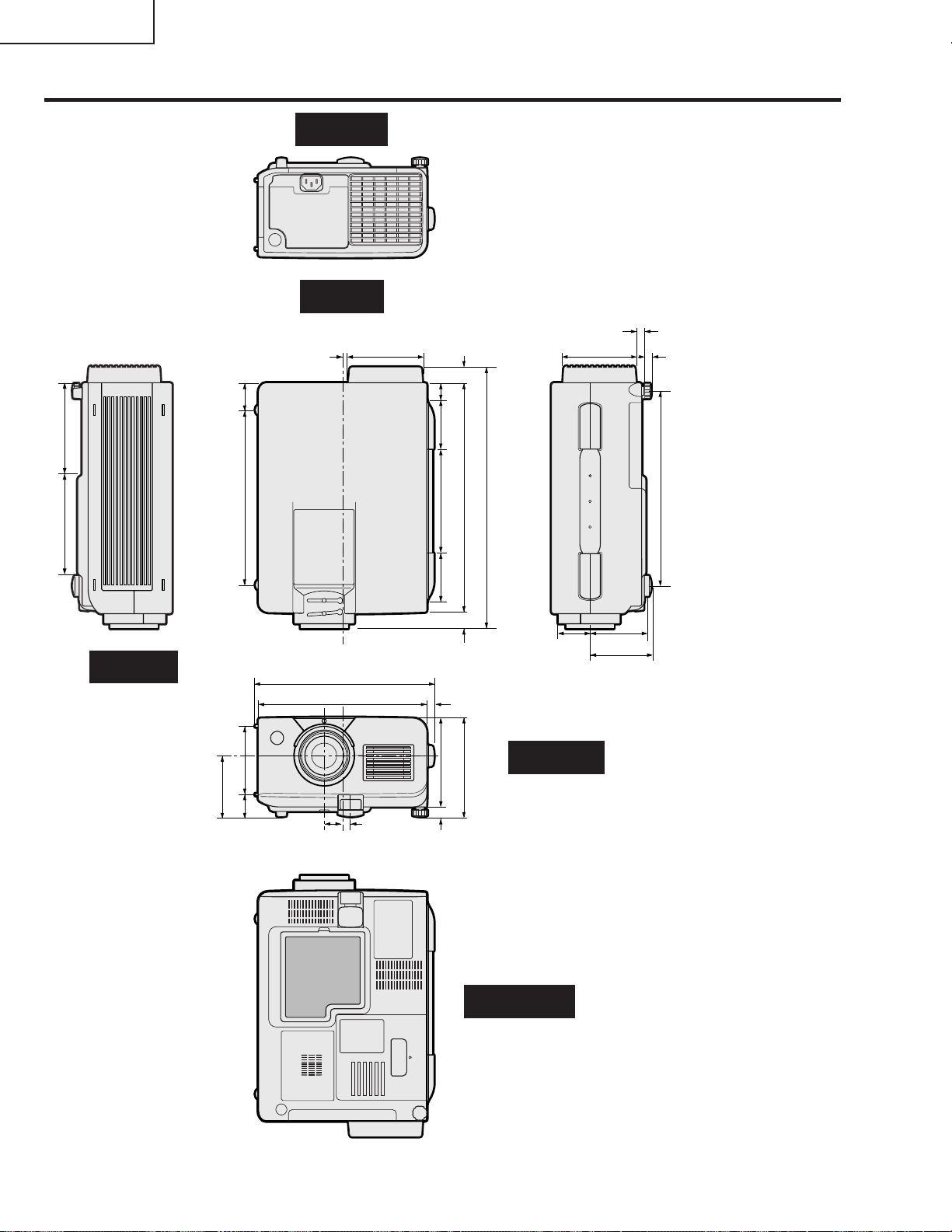
XG-C40XU/XE
Dimensions
(124.5)
64
/
1
(138.5) 49
64
/
33
54
(33.5)
16
/
5
1
(237.5)
32
/
11
9
Rear Vie
Top View
25
/64 (10)
53
/64 (97.5)
3
(27.5)
64
/
5
1
(61)5
32
/
13
2
(142)
32
/
19
(61)4
32
/
13
2
(23)
32
/
29
13
(310)5
64
/
12
(358.4)
64
/
7
14
3 51/64 (96.5)
23
/64 (9)
23
/64 (9)
(262)
16
/
5
10
Side View
(83)
64
/
17
3
(93)
32
/
21
3
(30)
16
/
13
1
63
/64 (25)
w
9 19/32 (243.5)
1
/64 (229)
9
7
/16 (11)
(16)
8
/
5
13
/32 (10.5)
(121)
64
(134)
/
32
/
49
9
(13)
32
/
17
Bottom View
11
1
/16 (43)
Front View
2
3
63
/64 (76)
17
/64 (83)
12
Units: inches (mm)
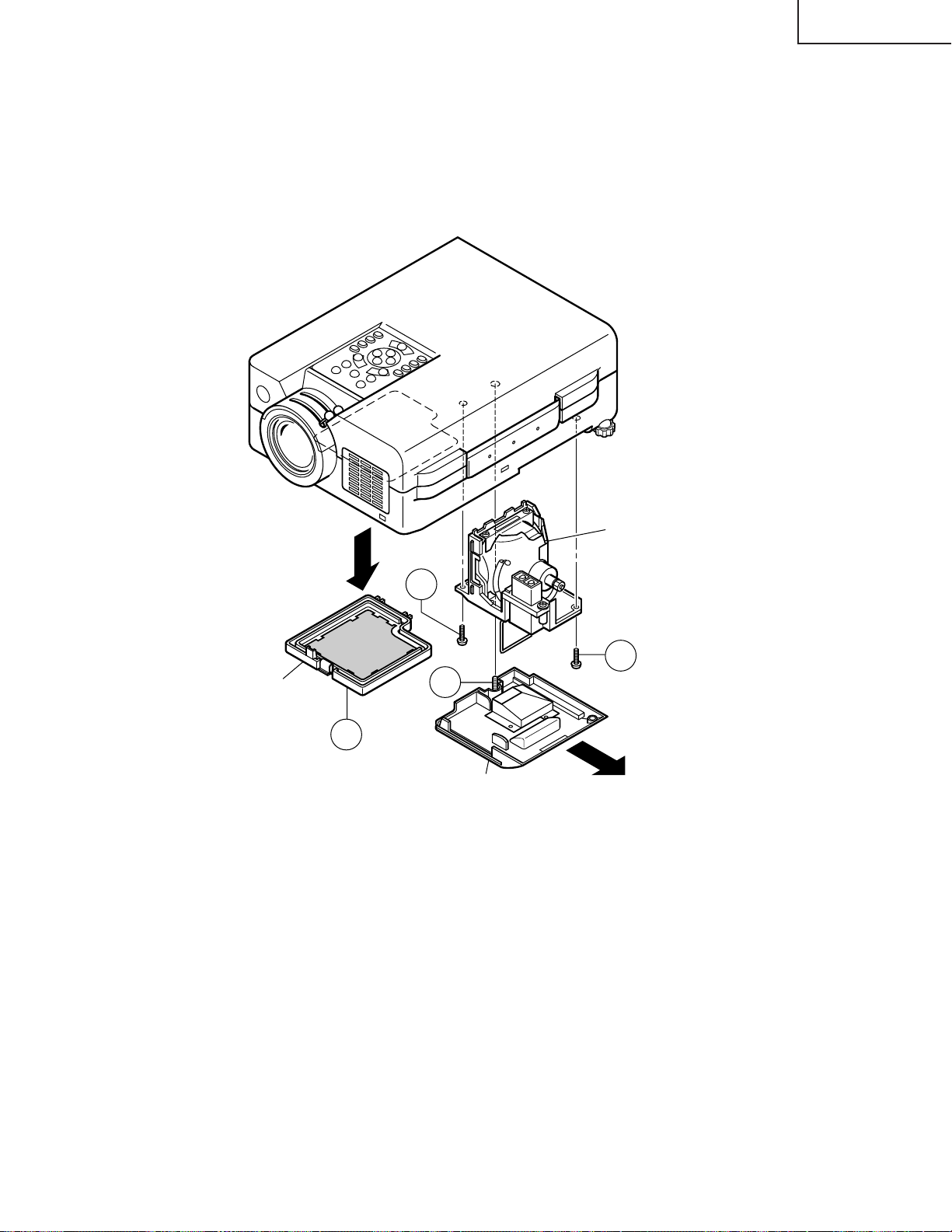
REMOVING OF MAJOR PARTS
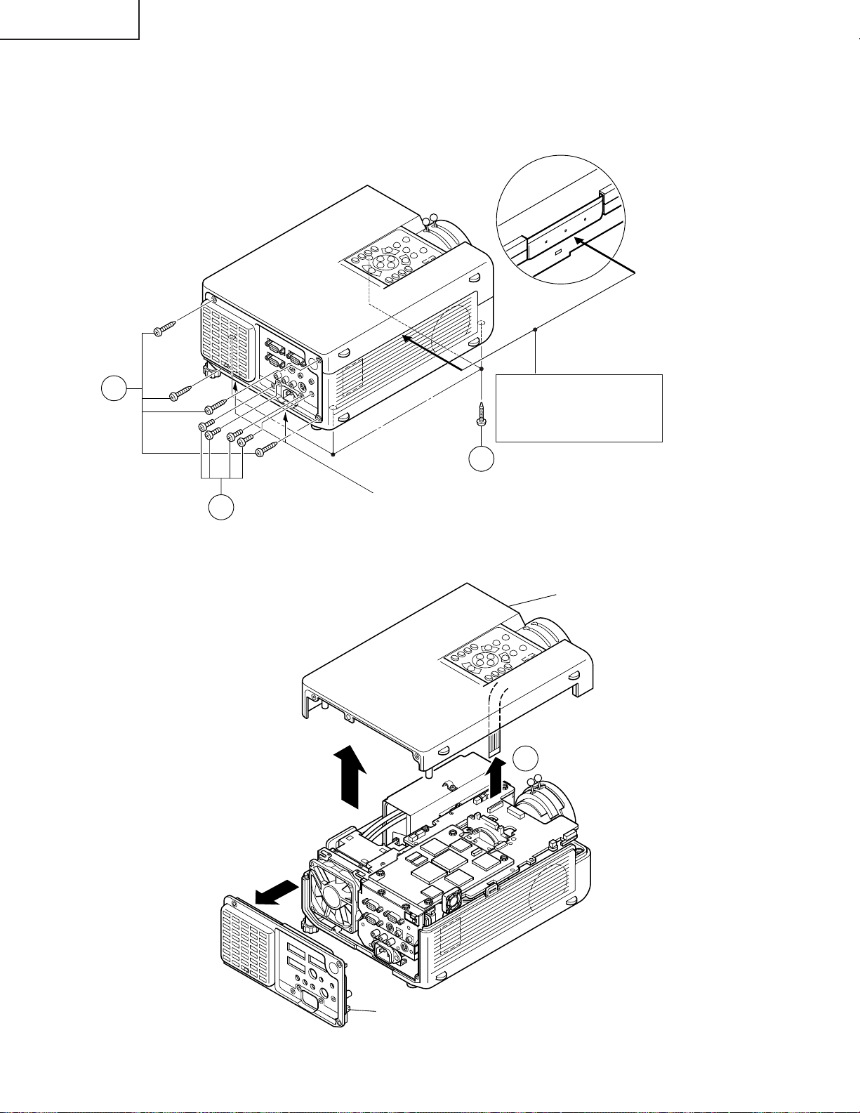
1.Removing the Intake cover and lamp unit
1-1. Detach the Intake cover.
1-2. Loosen the lamp cover screw and draw out the lamp cover in the direction of arrow (toward yourself).
1-3. Remove the two lamp unit lock screws. Detach the lamp unit.
SHARP
XG-C40XU/XE
Intake cover
Note:
When replacing the lamp, make sure
that there is a clearance of over
8mm between the terminal and the
lamp snap-on spring (and other
metallic parts).
Lamp unit
1-3
1-3
1-2
1-1
Lamp cover
13
XG-C40XU/XE
2.Removing the top and rear cabinets
2-1. Remove the four rear cabinet lock screws.
2-2. Remove the four terminal board lock screws off the rear cabinet. Unhook and detach the rear cabinet from
below.
2-3. Remove the four top cabinet lock screws from below.
SHARP
2-1
Press both sides of the bottom
cabinet in the directions of
arrow to undo the hooks. Lift
and detach the top cabinet.
2-3
Hook
2-2
2-4. Slowly lift the top cabinet and disconnect the operation key unit connector (KY). Then take away the top
cabinet.
Top cabinet
(KY)
2-4
Rear cabinet
14
XG-C40XU/XE
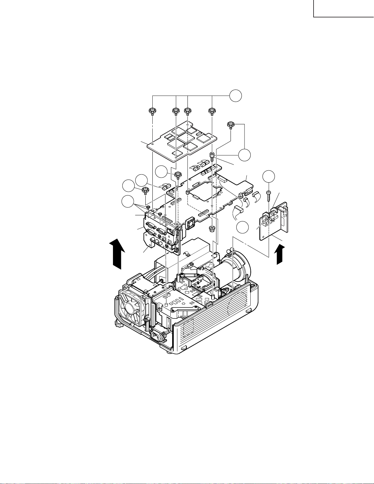
3. Removing the PWB units
3-1. Disconnect the connectors from the output unit.
3-2. Remove the four PC I/F unit lock screws.
Remove the two screws and the earth shield, and take out the PC I/F unit.
3-3. Remove the spacer (stud bolt) and the three screws off the output unit. Lift the output unit, together with the
signal unit, off the position.
3-4. Remove the S-out/REG unit angle lock screw and take out the S-out/REG unit.
3-2
PC I/F Unit
3-3
3-2
Signal Unit
PC Terminal Unit
Video Unit
3-1
(FP)
3-3
(FS)
(L)
(Q)
(TP)
(FN)
3-3
Spacer (stud bolt)
Output Unit
(EB)
(EB)
3-1
(F)
(SO)
(SO)
3-4
S-out/REG Unit Angle
(EA)
(SP)
S-out/REG Unit
15
XG-C40XU/XE
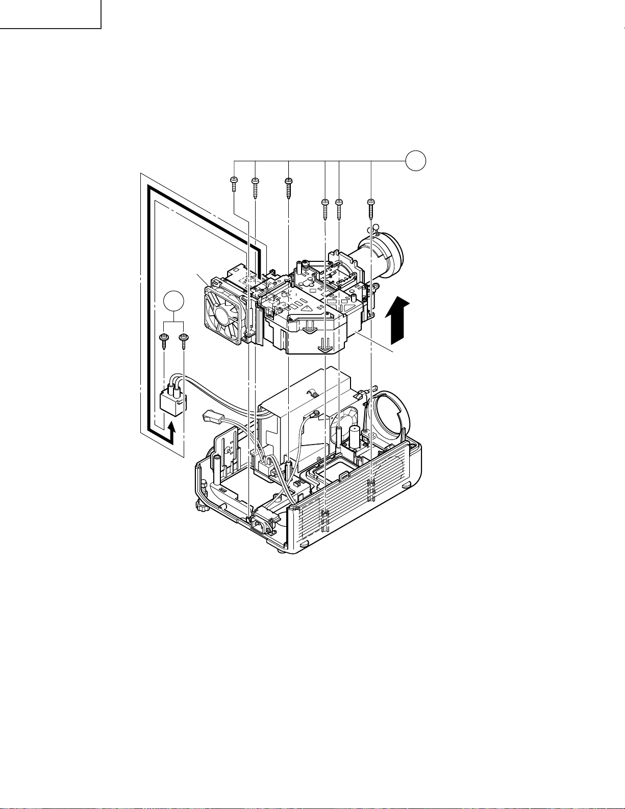
4.Removing the optical mechanism unit
4-1. Remove the six optical mechanism unit lock screws. Lift the unit off the position.
4-2. Remove the two lamp socket holder lock screws and take out the holder.
Duct Fan Unit
4-2
4-1
Optical Mechanism Unit
16
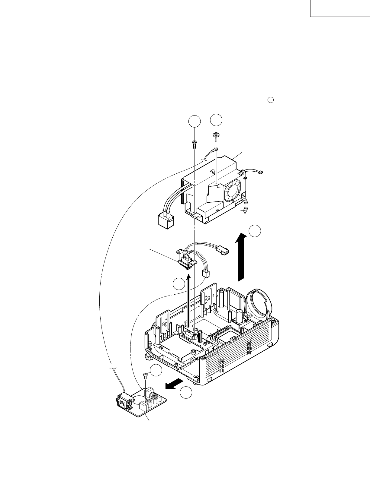
5.Removing the Power/Ballast unit assembly
5-1. Remove the Power/Ballast unit assembly lock screw.
5-2. Remove the (FG) lead lock screw.
5-3. Lift the Power/Ballast unit assembly off the position.
6.Removing the ballast unit and inlet unit
6-1. Disconnect the connector (PA) from the inlet unit. Take out the AC power switch.
6-2. Remove the Inlet unit lock screw.
6-3. Pull the inlet unit toward yourself off the position.
Note: Before installing the lamp cover, make sure the AC power switch is at the " " (OFF) position.
XG-C40XU/XE
AC power switch
(for Lamp replacement)
6-1
5-1
(FG)
5-2
Power/Ballast Unit Ass'y
(TP)
5-3
(BA)
(PA)
(FG)
6-2
(PA)
6-3
Inlet Unit
17
XG-C40XU/XE
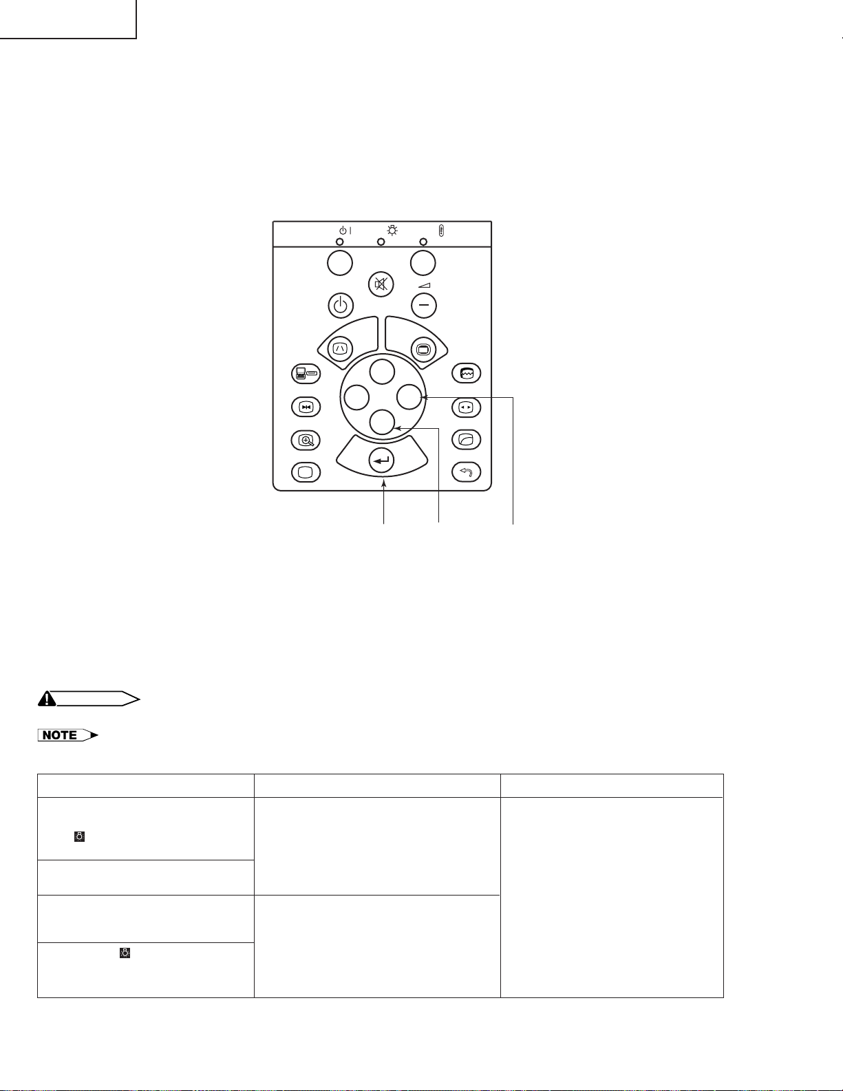
RESETTING THE TOTAL LAMP TIMER
When the lamp has been replaced, reset the total lamp timer in the following steps.
Resetting procedure
1. While holding down the “ENTER”, “ADJ."” and “ADJ.|” keys on the set at the same time, turn on the main
power switch (located side the AC inlet).
2. Now the total lamp timer is reset to zero. “000H” appears on the screen.
POWER
ON
OFF
INPUT
FREEZE
ENLARGE
BLACK SCREEN
B
LAMP
MUTE
I
KEYSTONE
'
ENTER ADJ." ADJ.|
TEMP.
+
VOLUME
MENU
AUTO
'
'
'
ENTER
SYNC
RESIZE
GAMMA
UNDO
Lamp
The lamp in this projector operates for approximately 2,000 cumulative hours, depending on the usage environment. It is recommended that the lamp be replaced after 1,900 cumulative hours of use or when you notice a
significant deterioration of the picture and colour quality. The lamp usage time can be checked with the On-screen
Display.
CAUTION
• Intense light hazard. Do not attempt to look into the aperture and lens while the projector is operating.
• As the usage environment can vary significantly, the projector lamp may not operate for 2,000 hours.
Condition
The LAMP REPLACEMENT
indicator lights up red, and “LAMP”
and “ ” will flash in yellow in the
lower-left corner of the picture.
A significant deterioration of the
picture and colour quality occurs.
The power will automatically turn
off and the projector will enter
standby mode.
Problem
• Lamp has been used for over 1,900
hours.
• Lamp has been used for over 2,000
hours.
• Purchase a replacement lamp unit
(lamp/cage module) of the current
type BQC-XGC40XU/1 from your
nearest Sharp Authorised LCD
Projector Dealer or Service Centre.
• Replace the lamp. If you wish, you
may have the lamp replaced at
your nearest Sharp Authorised
LCD Projector Dealer or Service
Centre.
Possible Solution
“LAMP” and “ ” will flash in red in
the lower-left corner of the picture,
and the power will turn off.
18
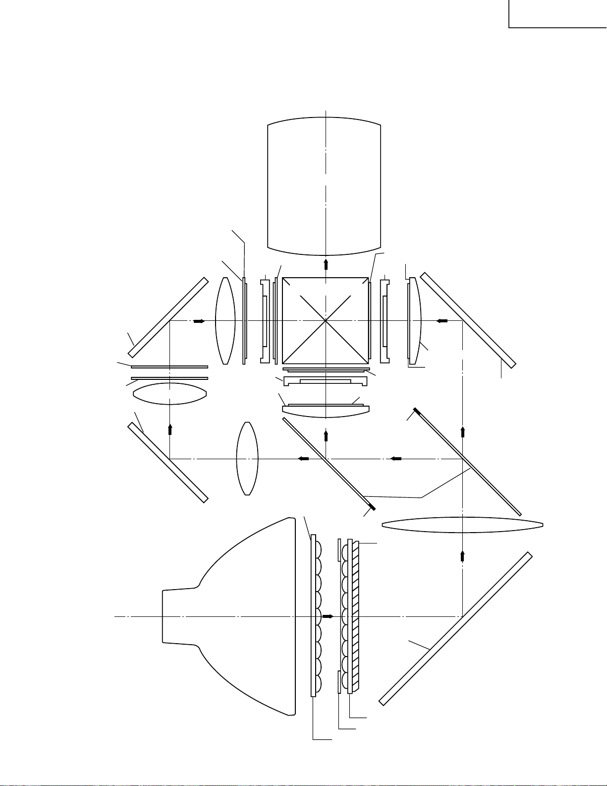
THE OPTICAL UNIT OUTLINE
Layout of the optical system
Note: Layout for positioning the optical system.
Incident polarizing plate B
XG-C40XU/XE
Projection Lens
M4/M6
Dichroic coating
(B reflection)
UV-filter(0.8t)
UV-filter
Dichroic coating
(B reflection)
M4/M6
AR coating
B reflector
Relay lens 3
Relay lens 2
B reflector
BLUE
RL3
RL2
emergent polarizing
B-LCD
G-LCD
Dichroic coating
(G transmission)
CL3
RL1
Relay lens 1
plate B
Cross dichroic prism
Porarizing film
Condenser lens G
GREEN
BLUE
G reflector
M3
UV-IR coating
Marking
emergent polarizing plate R
Dichroic coating (R transmission)
R-LCD
R-reflector
CL2
Condenser lens R
emergent
polarizing plate G
Marking
(Bottom)
Dichroic coating
Porarizing film
M5
Dichroic coating
(R reflection)
RED
M2
B/G reflector
DC lamp
(Light source)
PBS(polarization
beam splitter)
Ag-deposited
face
Fly-eye lens (outgoing light)
Fly-eye aperture
Fly-eye lens (incoming light)
19
CL1
M1
Ag-coated mirror W

XG-C40XU/XE
CONVERGENCE AND FOCUS ADJUSTMENT
» Start the convergence and focus adjustments with the top panel removed but the power
on. Use the remote control to adjust the image.
Take the following procedures.
1. Focusing the projection lens
(A) Replacing all the 3 LCD panels
1. Before replacing all the 3 LCD panels, project an image on the screen and bring it into focus.
2. Replace the LCD panels with new ones. But until the focus has been completely readjusted, be careful not
to change the projection distance between the set and the screen, nor to move the projection lens focus
and zoom rings.
Note:
If the focus is readjusted with a different positional relation, the relation between the projection distance
and the screen size is affected. In other words, a short-distance image (40 WIDE for example) may get out
of the focus range, or a long-distance image (300 WIDE for example) may come out of the focus.
(B) Replacing 1 or 2 of the 3 LCD panels
1. In adjusting the focus after replacement of one or two LCD panels, project an image on the screen and turn
the projection lens focus ring to get the non-replaced LCD panel into focus.
2. But until the focus has been completely adjusted for the new LCD panels, be careful not to change the
projection distance between the set and the screen, nor to move the projection lens focus and zoom rings.
3. If the projection distance has been changed or the projection lens readjusted, repeat the above steps 1 and
2.
2. Focus adjustment
(A) Adjusting the G-LCD panel(Make this adjustment on the white-only screen.)
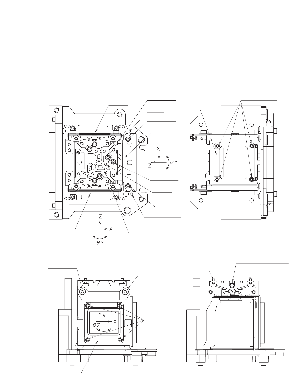
1. Adjustment in θX and Z directions .
Loosen the lock screw "a" and insert an eccentric screwdriver into the notch and hole "a". Turn the screwdriver
until the top, center and bottom on the screen get into focus. In adjusting this top-to-bottom focus, tighten
the lock screws "b" and "c" to fix the θY direction adjustment.
First get the right and left halves in balance. Then improve the accuracy while making the adjustment 2
below.
2. Adjustment in θY direction
T emporarily tighten the lock screw "a" and loosen the lock screws "b" and "c". Insert the eccentric screwdriver
into the notch and hole "c" for adjusting in the θY direction on the top of the screen. Insert the eccentric
screwdriver into the notch and hole "b" for adjusting in the θY direction on the bottom of the screen.
3. Repeat the above steps 1 and 2 to finely adjust the focus. Finally tighten up all the lock screws.
Notes :
1 Carefully proceed with the focus adjustment because the adjusting directions are correlated.
2 In adjusting the convergence and focus, do not move the projection lens zoom and focus rings until the end
of all the adjustments.
(B) Adjusting the B-LCD panel (Do the same for the R-LCD panel.)
1. Take the same procedure as for the G-LCD panel focus adjustment. Note that the adjustment range is
wider in the Z direction. If the convergence is quite different between the B-LCD and G-LCD panels,
roughly adjust the convergence first and then the focus.
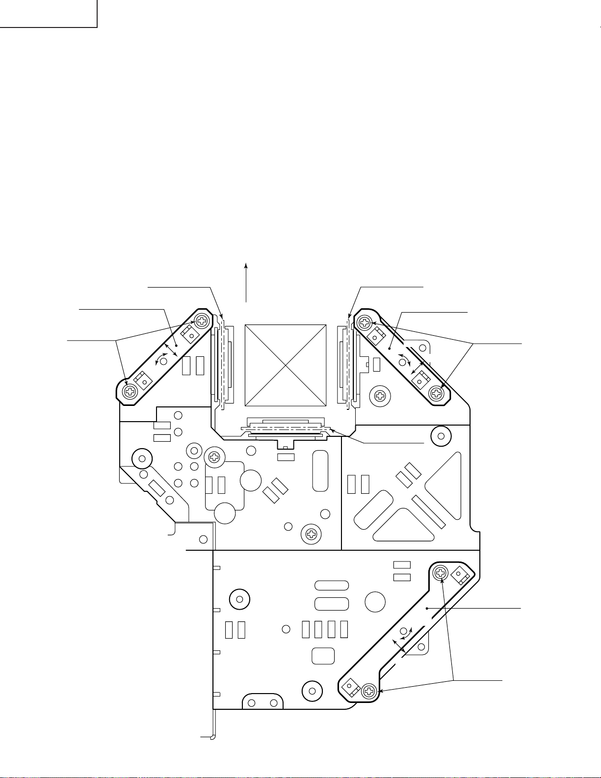
3. Convergence adjustment
» Use a crosshatch pattern signal for this adjustment.
Make the adjustment just for the G-LCD and the relevant colour.
1. Loosen the convergence lock screw "d".
2. Adjustment in Y and θZ directions
Put a hex wrench in the Y and θZ direction adjustment zone.
3. Adjustment in X direction
Put an eccentric cam adjusting wrench in the X direction adjustment zone.
20
R-LCD
B-LCD
Lock screw "a"
Lock screw "c"
Notch and
hole "c"
Notch and
hole "b"
Lock screw "c"
G-LCD
G-LCD
Lock screw "b"
Notch and hole "c"
Notch and hole "a"
Lock screw "d"
Lock screw "d"
R·B-LCD panel
mounting screws
(four screws)
R·B-LCD
SIDE VIEW (from inside)
SIDE VIEW (from outside)
TOP VIEW SIDE VIEW
G-LCD panel
mounting screws
Eccentric cam
(Y direction adjustment)
Eccentric cam
(X direction adjustment)
Eccentric cam
(θZ direction adjustment)
(four screws)
4. With the G-LCD panel's screen center as refernce, adjust the R-LCD and B-LCD panels.
5. Finally tighten up the convergence lock screw "d".
Notes :
1 The eccentric cam is used for convergence adjustment.
This means that the cam's turning and the linear movement are not always uniform.
2 This model is not equipped with the LCD image adjustment mechanism. This is because the cross-dichroic
prism is used for image formation. When the LCD panels all get into best focus, the images are almost
completely converged.
Convergence and Focus Adjustments Mechanism
XG-C40XU/XE
21
XG-C40XU/XE
80
2
2
92
5
7.5
0.5
min85
ø5
ø3.5
3.5
Convergence and Focus Adjustments at a Glance
Adjustment directions
Adjustment Direction Definition Direction of LCD panel
X direction LCD right and left
Convergence Y direction LCD top and bottom
θZ direction Rotation around Z axis LCD turning axis
Z direction LCD optical axis
Focus θX direction Rotation around X axis LCD top-to-bottom flapping
θY direction Rotation around Y axis LCD right-to-left flapping
Convergence and Focus Adjustment for the Optical Mechanism
Colour Adjustment Direction
X direction ±0.8mm Eccentric cam Eccentric cam adjusting wrench d Hex wrench
Convergence Y direction ±0.8mm Eccentric cam Eccentric cam adjusting wrench d Hex wrench
R/B θZ direction ±1° Eccentric cam Eccentric cam adjusting wrench d Hex wrench
colours Z direction ±0.8mm
Focus θX direction ±1°
θY direction ±1°
Z direction ±0.2mm
G colour Focus θX direction ±1° Same as for R and B colours
θY direction ±1°
Movement
Position Adjusting tool
Notch and hole "a" & "c"
Notch and hole "a" & "c"
Notch and hole "b" & "c"
Eccentric screwdriver, a, c
Bladed screwdriver a, c
Lock screw
b, c
Tightening tool
Phillips
screwdriver,
*Hex wrench
Focus Adjustments the Other Way
Lock screw Position Related direction
a Notch and hole "a" Z and θX directions
b Notch and hole "b" θY direction
c Notch and hole "c" Z, θX and θY directions
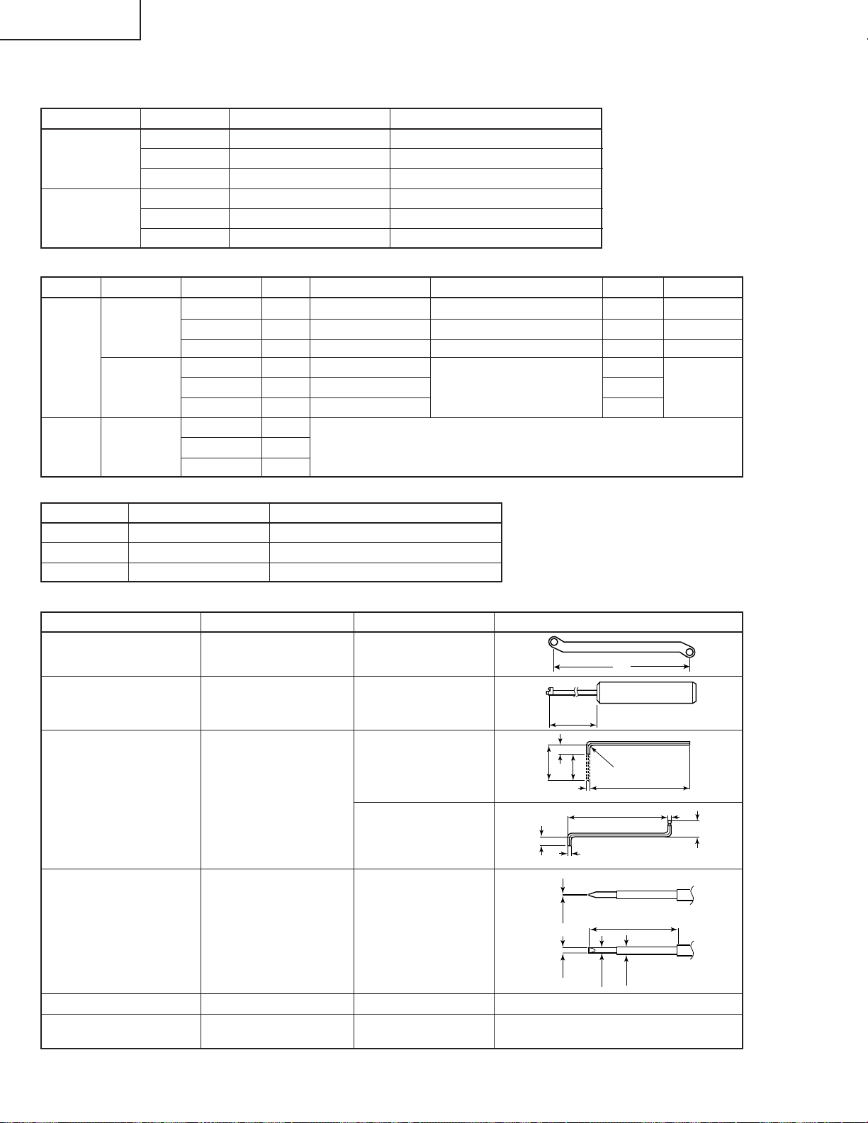
Convergence and Focus Adjusting and Tightening Tools
Tool Specific or General Tool code Configuration
Eccentric cam
adjusting wrench
Specific 9DASPN-XGNV1U
Eccentric screwdriver Specific 9DADRiVER-NV4U
9EQLNC-XGNV1U
Hex wrench General (redesigned)
9EQLNC-XGNV4U
100
5
16
CUT
R2
50
2
Bladed screwdriver General 9EQDRiVER-NV1B
Phillips screwdriver General — For M2.6 pan-head machine screw
*Hex wrench General —
22
1.27mm, preferably use a 70 mm or
longer screwdriver (with a handle).
XG-C40XU/XE
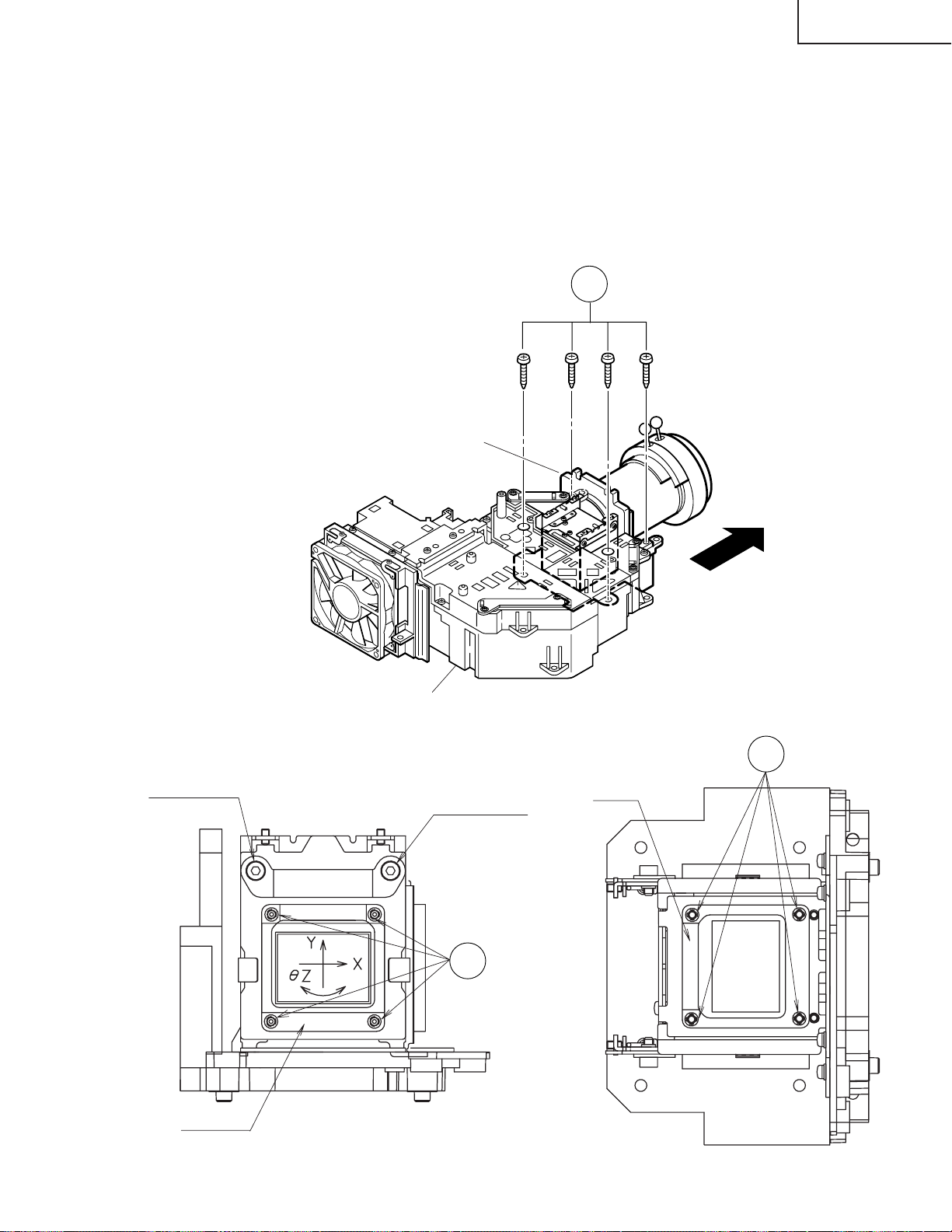
Replacing the LCD panels
Detach the top panel and the optical mechanism unit in advance.
(1)Remove the four prism holder lock screws. Detach the prism holder from the optical mechanism unit.
(2)Remove the LCD panel lock screws (four each for the R-, G- and B-LCD panels). Detach the LCD panels from the
prism holder.
(3)Mount a new LCD panel in the reverse order of the above steps (1) and (2).
~ Readjust the convergence and focus. Note that the G-LCD panel needs no convergence adjustment and has
a small adjustment range in the Z direction.
1
Prism holder
SIDE VIEW (from inside)
Lock screw "d"
R·B-LCD
Optical Mechanism Unit
Lock screw "d"
2
R·B-LCD panel
mounting screws
SIDE VIEW
G-LCD
G-LCD panel
mounting screws
2
23
XG-C40XU/XE
Adjusting the optical axis of the mirrors (M1, M5 and M4/M6)
The optical axis must be readjusted if an eclipse happens with the R. G or B mirrors. Generally speaking,
this adjustment is needed when any of the internal optical components has been replaced.
Adjustment procedure required when any of the panels has been replaced or the convergence has been
adjusted
(1)Disconnect the flat cables of all the LCD panels.
(2)Let the lamp light up.
(3)To adjust the G mirror, shield the R and B mirrors with shielding plates (You can use a business card or the like to
block the light).
(4)Loosen the lock screw of the M1 adjust lever.
(5)Looking at the G image on the screen, turn or slide the M1 adjust lever until the eclipse on the screen disappears.
Tighten up the screw.
(6)To adjust the R mirror, shield the G and B mirrors and adjust the M5 adjust lever. For the B mirror , shield the R and
G mirrors and adjust the M6 adjust lever.
(Take the same steps 4 and 5 above.)
(7)Remove all the shielding plates to have a white image.
Make sure there is no eclipse.
M4/M6
Lock screws
Shielding plate B
adjust lever
slide
turn
FRONT
Shielding plate R
M5 adjust lever
turn
Shielding plate G
Lock screws
slide
24
M1 adjust lever
turn
slide
Lock screws
XG-C40XU/XE
ELECTRICAL ADJUSTMENT
Hook up a signal generator, or a DOSV or Mac personal computer to the projector in order to feed the
signals specified in the Adjusting conditions.
No. Adjusting point Adjusting conditions Adjusting procedure
1 EEPROM
initialization
1. Turn on the power (make
sure the lamp lights up) and
warm up the unit for 15 minutes.
» Make the following settings:
Press SW5101 to call up the process mode and
execute S2 in the SSS menu. Now the system,
with the PC board not included, is initialized. Do
not execute S1 because otherwise the PC board
will be initialized.
To adjust the PC board, follow the instruction in
"Adjusting the PC board". (See page 31)
2 3.3V power
supply
adjustment
3 2.5V power
supply
adjustment
4 R drive » Using the control switches or the remote controller
5 B drive 1. Feed the 100% blue-only
6 G drive 1. Feed the 100% green-only
1. Turn on the power.
2. Connect the digital voltmeter to TP1446.
1. Turn on the power.
2. Connect the digital voltmeter to TP1447.
1. Feed the 100% red-only signal. Make the following
choice.
Group : A/D
Subject : R-D
signal. Make the following
choice.
Group : A/D
Subject : B-D
signal. Make the following
choice.
Group : A/D
Subject : G-D
» Adjust R1649 so that the voltmeter should read
3.43 ±0.03 Vp-p.
» Adjust R1652 so that the voltmeter should read
2.60 ±0.05 Vp-p.
buttons, adjust the data so that the signal becomes bit-less (noise).
» Using the control switches or the remote controller
buttons, adjust the data so that the signal becomes bit-less (noise).
» Using the control switches or the remote controller
buttons, adjust the data so that the signal becomes
bit-less (noise).
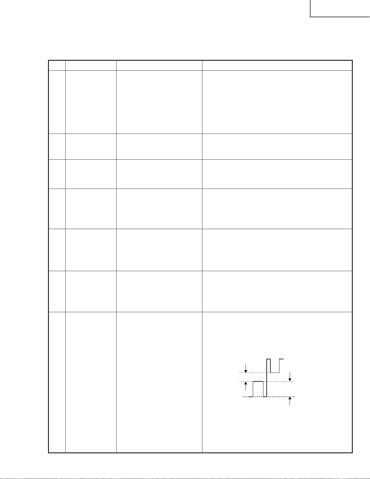
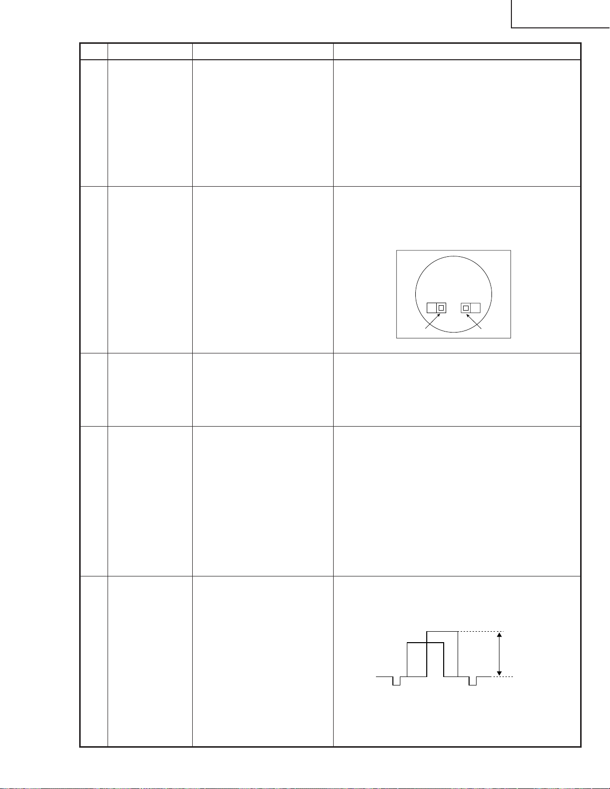
7 RGB 1 system
black level
signal amplitude
(odd-numbered)
1. Make the following choice:
Group : OUTPUT 1
Subject : G1-BLK
G1-GAIN
For red, choose the sub-
jects R1-BLK and R1-GAIN.
For blue, choose the subjects B1-BLK and B1-GAIN.
2. Connect the oscilloscope to
TP1101 for red.
TP1201 for green
TP1301 for blue
25
» Choose the subject G1-GAIN and adjust the sig-
nal amplitude to 3.3 ±0.1 Vp-p using the control
switches or the remote controller buttons.
» Next,choose the subject G1-BLK and adjust the
white to white level to 2.6 ±0.1V DC.
(Adjust to 2.6V
DC for red and
blue.)
» Adjust the signal's amplitude and white to white
level to 3.3 ± 0.1Vp-p and 2.6 ± 0.1V DC, respectively, for red and blue.
2.6V
3.3Vp-p
(Adjust to 3.3Vp-p
for green and blue.)
XG-C40XU/XE
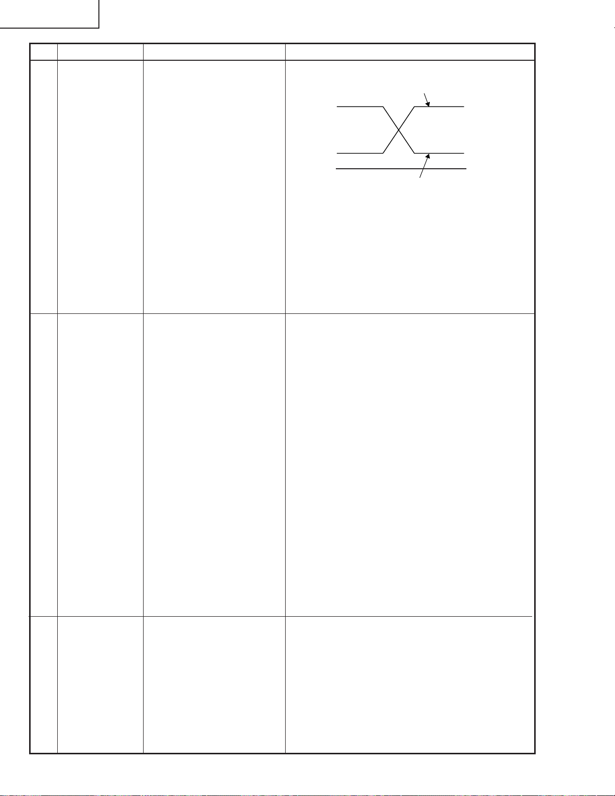
No. Adjusting point Adjusting conditions Adjusting procedure
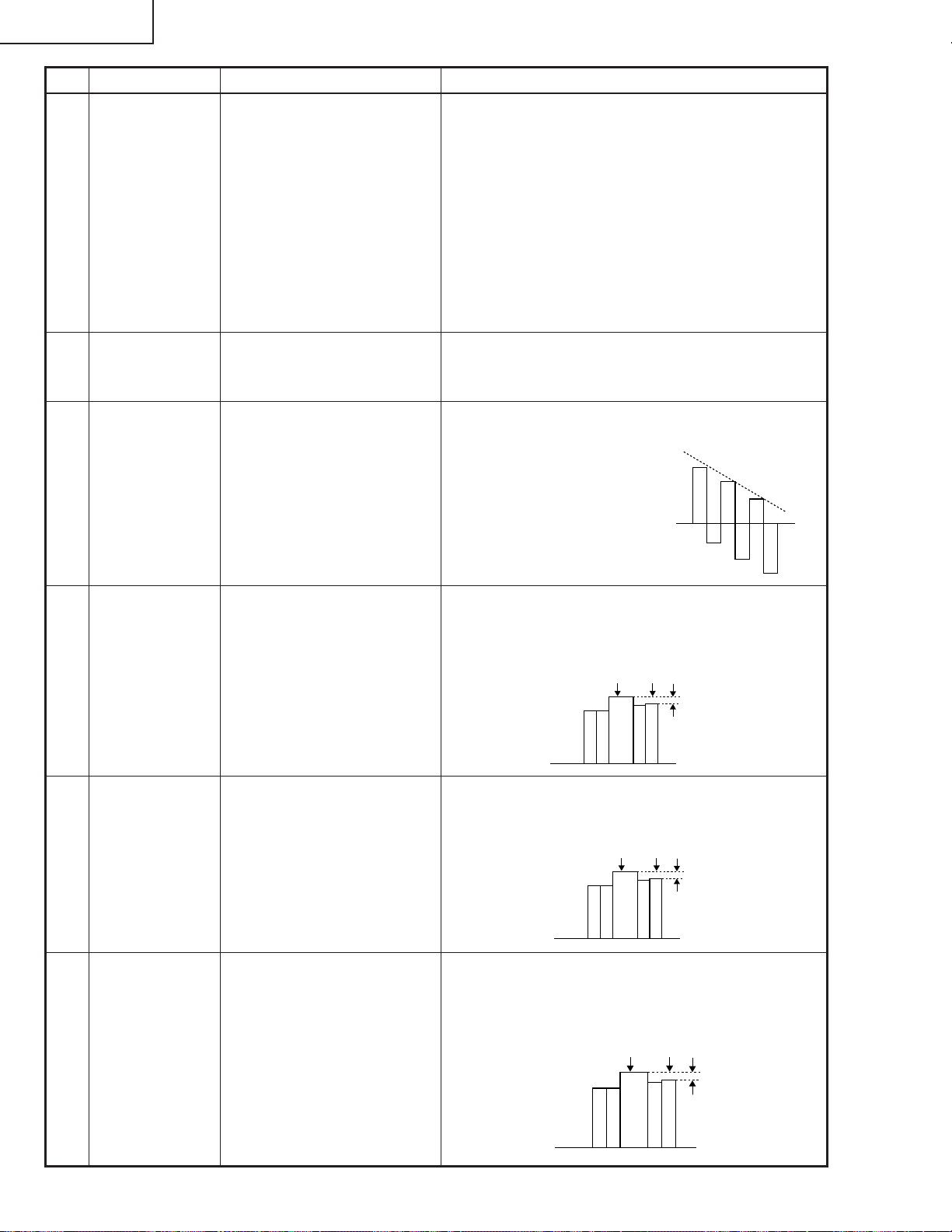
8 P SIGNAL 1. Connect the oscilloscope to
TP1701 for red.
TP1702 for green
TP1703 for blue.
2. Make the following choice:
Group : OUTPUT 2
Subject : PSIG-H
: PSIG-L
9 Panel ghost
adjustment
1. Project the XGA60Hz ghost
test pattern (black charac-
ters in bold on the halftone
RGB background).
Group: OUTPUT3
2. GCK-PHASE adjustment
Make sure the setting is fixed
at 8 (initial value).
3. EN-WIDTH adjustment
Make sure the setting is fixed
at 8 (initial value).
4. ENR-PHASE adjustment (R-
LCD ghost adjustment)
5. ENG-PHASE adjustment
(G-LCD ghost adjustment)
6. ENB-PHASE adjustment (B-
LCD ghost adjustment)
» Adjust the PSIG waveform to the one shown below.
(Adjust with PSIG-H.)
PSIG
(Adjust with PSIG-L.)
» For the green and blue colours, make sure their wave-
forms are similar to that of the red colour.
» Make sure the pin stripe of every 12 dot doesn't ap-
pear at 10 steps signal of side nays.
(Appearing white pin stripe or black one, adjust the
PSIG-H.)
» ENR-PHASE adjustment (R-LCD ghost adjustment)
1 Increase the setting until a ghost image (see
Note) becomes visible at the left of the back
characters on the R half-tone background.
2 Lower the setting point by point until the left-
hand ghost image (1 above) disappears.
3 Further lower the setting by one point.
» ENG-PHASE adjustment (G-LCD ghost adjust-
ment)
Adjust the G ghost image by following the same
procedures described under step 1 above.
» ENB-PHASE adjustment (B-LCD ghost adjust-
ment)
Adjust the B ghost image by following the same
procedures described under step 1 above.
Note: Left-hand ghost image: Characters are shown
double 12 dots left from the real characters.
Reference: This adjustment is made because the
EPSON LCD panel may have 1- or 2point differences due to lot-by-lot variations.
6.2±0.2V DC
2.0V DC
GND
10 Sample-and-
hold pulse
phase
RCK-PHASE
GCK-PHASE
BCK-PHASE
1. Feed the XGA mode 75-Hz
black signal.
2. Make the following choice:
Group : OUTPUT 3
Subject : SH-PHASE
(Have the standard level at
2.)
Fix the RCK-, GCK- and
BCK-PHASE settings all to
8.
» Using the control switches or the remote controller
buttons, make sure that the “OUTPUT 3” characters are not blurry and there is no ghost image. If
such blur or ghost occurs, finely adjust the setting
in the range of 7~9.
26
1
2
No. Adjusting point Adjusting conditions Adjusting procedure
XG-C40XU/XE
11 RGB counter-
voltage
adjustment
12 RGB gradation
regeneration
adjustment
1. Feed the black-and-red
(25%) stripe signal (XGA).
2. Make the following choice:
Group : OUTPUT 3
Subject : RC (R)
and
Group : OUTPUT 3
Subject : RC-INV (R)
1. Feed the green-only SMPTE
pattern signal (XGA).
Group : OUTPUT 1
Subject : G1-BLK
» Using the control switches or the remote controller
buttons, adjust the data in order to minimize the
flicker.
» Make the same adjustment for BC (B), GC (G),
RC-INV (B) and RC-INV (G).
» See if the image is equally adjusted at the center
and both sides of the screen. If not, readjust the
setting to have the image equal at right and left.
» Adjust the G-BLK data until the gradation of the
portion 1 (95% and 100% white) shown below
can be slightly recognized. Make sure also that the
gradation of the portion 2 (0% and 5% black) is
visible.
13 RGB white
balance
14 Horizontal
center
15 Video picture
adjustment
1. Feed the 32-step gray scale
signal (XGA).
Group : OUTPUT 1
Subject : R1-BLK (R)
B1-BLK (B)
1. Feed the NTSC monoscope
pattern signal.
2. Group : VIDEO 2
Subject : N358-DLY (4)
N443-DLY (0)
PAL-DLY (3)
SECAM-DLY (0)
Make sure the settings are
as above.
3. Group : VIDEO 1
Subject : NTSC-H
1. Feed the split colour bar signal.
Group : VIDEO 1
Subject : PICTURE
2. Connect the oscilloscope
between pin (2) of P801 and
GND.
» Choose the subjects R1-BLK and B1-BLK and
adjust the black balance of the gradation.
» Using the control switches or the remote controller
buttons, adjust the data to have the same
overscan.
» Using the control switches or the remote controller
buttons, adjust the black-to-white (100%) level
difference to 2.0 ±0.02 Vp-p.
2.0Vp-p
27
XG-C40XU/XE
100% White Red
No. Adjusting point Adjusting conditions Adjusting procedure
16 Video
brightness
adjustment
1. Feed the baseband (split
colour bar) signal. (The ONAIR signal is not accepted
because of its too much
noise.)
Group : VIDEO 2
Subject :
VROS/VGOS/VBOS
2. Press the control switch or
the remote control’s mute
button (to set the gamma
correction to the process
setting).
17 Video AGC 1.
Feed the split colour bar signal.
Group : VIDEO 1
Subject : AGC
18 Tint 1. Feed the split colour bar
signal.
Group : VIDEO 1
Subject : TINT
2. Connect the oscilloscope to
pin (4) of P801.
» Using the control switches or the remote controller
buttons, adjust the setting until the black signal
becomes bit-less.
» Using the control switches or the remote controller
buttons, adjust the setting until the white signal
becomes bit-less.
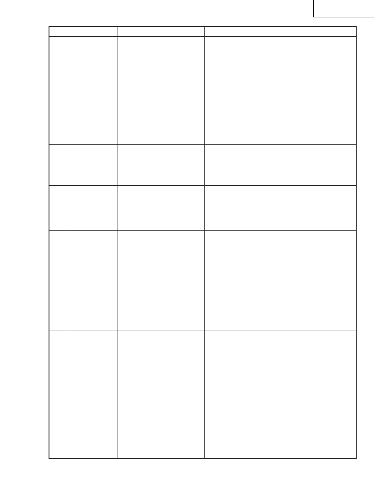
» Using the control switches or the remote controller
buttons, adjust the data to have the -(B-Y) waveform downhill straight.
» After adjusting, adjust the
value of TINT up 3 point.
19 NTSC colour
saturation level
20 PAL colour
saturation level
21 SECAM colour
saturation level
1. Feed the split colour bar signal.
Group : VIDEO 1
Subject : N-COLOR
2. Connect the oscilloscope to
pin (1) of P801.
1. Feed the PAL colour bar signal.
Group : VIDEO 1
Subject : P-COLOR
2. Connect the oscilloscope to
pin (1) of P801.
1. Feed the SECAM colour bar
signal.
Group : VIDEO 1
Subject : S-COLOR
2. Connect the oscilloscope to
pin (1) of P801.
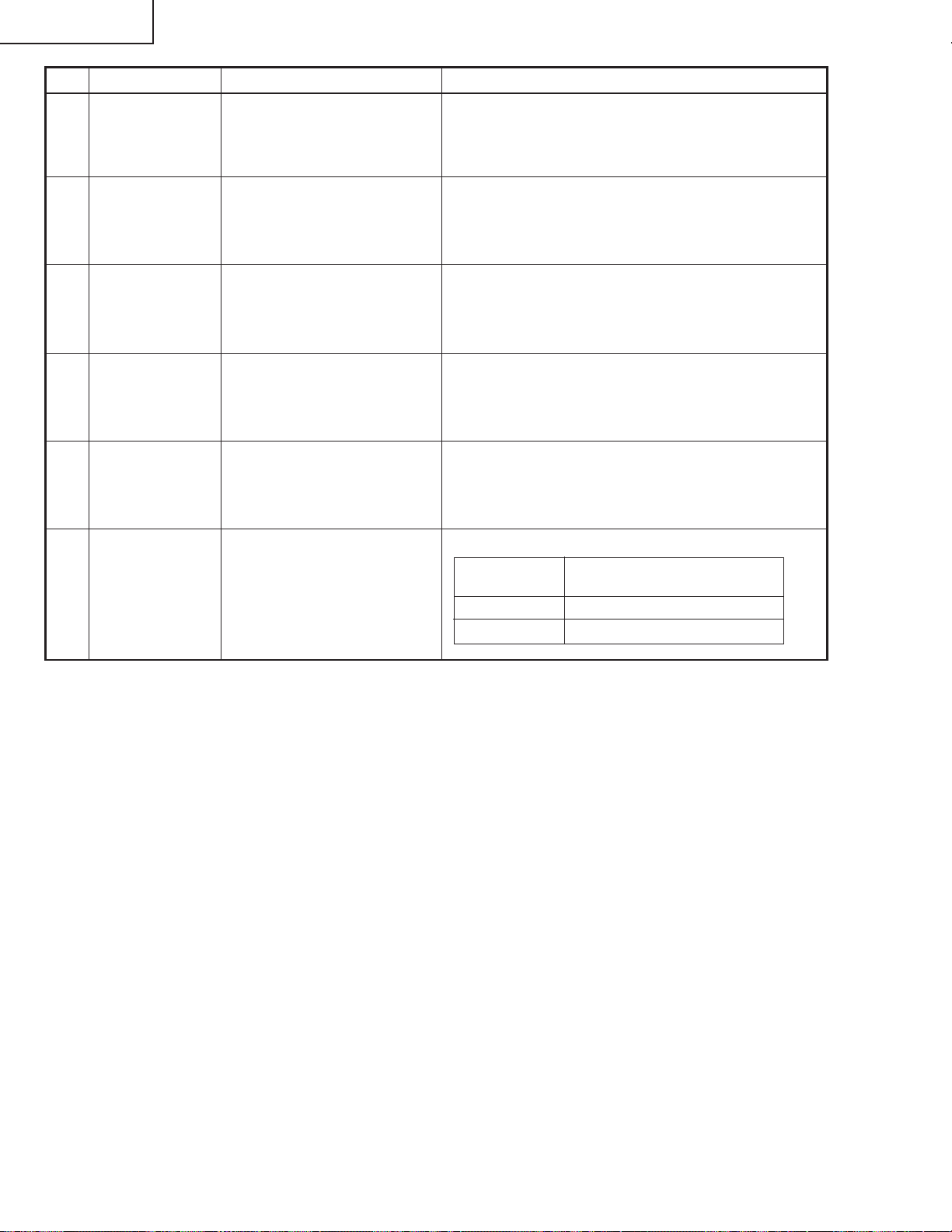
» Using the control switches or the remote controller
buttons, adjust the difference between the 100%
white portion and the red portion to 0.00 ±0.05 Vp-p.
(same as 100% white)
» Using the control switches or the remote controller
buttons, adjust the difference between the 100%
white portion and the red portion to 0.2 ±0.05 Vp-p.
100% White Red
» Using the control switches or the remote controller
buttons, adjust the data to have a level difference
of 0.2 ±0.05 Vp-p between the 100% white portion
and the red portion.
100% White Red
28
No. Adjusting point Adjusting conditions Adjusting procedure
XG-C40XU/XE
22 Video input
panel signal
amplitude
adjustment
23 Video white
balance
24 DTV white
balance
1. Feed the NTSC 10-step signal.
2. Select the following group
and subject.
Group: VIDEO2
Subject: R1-GAIN
B1-GAIN
3. Connect the oscilloscope to
TP1 101 (R) and TP1201 (G).
4. For the blue colour, connect the oscilloscope to
TP1301 (B) and TP1201
(G).
1. Feed the NTSC monoscope
pattern signal
Group : VIDEO 2
Subject : R1-BLK
B1-BLK
1. Feed the monoscope pattern
signal.
2. Group: DTV
Subject: CR-OFFSET
CB-OFFSET
» Select R1-GAIN and adjust the setting so that the
R and G signals have the same amplitude.
» For the blue colour, adjust the setting the same
way.
» Using the control switches or the remote controller
buttons, adjust so that the entire screen looks
evenly colourless.
» Using the control switches or the remote controller
buttons, adjust so that the entire screen looks
evenly colourless.
25 Setup 1. Group: VIDEO1
Subject: SET UP B
SET UP C
26 Automatic
colour correction
27 Colour system
performance
check
28 Video system
performance
check
29 Audio system
performance
check
1. Using the colour correction
system (ccdc), apply automatic colour correction.
1. Receive the colour bar signal.
1. Receive the monoscope pattern signal.
» Make sure the settings are 11 for SET UP B and 2
for SET UP C.
» Make sure there is no noticeable colour irregularity
left on the screen.
» In the process mode and select L1. Check the col-
our and tint.
» In the process mode and select L2. Check the pic-
ture, brightness and sharpness.
» In the process mode nad select L3. Check the bass,
treble.
29
XG-C40XU/XE
No. Adjusting point Adjusting conditions Adjusting procedure
30 RGB
performance
check
31 Off-timer
performance
check
32 Thermistor
performance
1. Receive the RGB signal. » In the process mode and select L4. Check the picture, brightness, red, blue, clock, phase, horizontal
position, and vertical position.
» In the process mode and select OFF. Make sure that
the off-timer starts with “5” (minutes), counts down each
minute in 1 second, and turns off the set at “0”.
1. Heat the thermistor using a
» Make sure the “TEMP” is displayed.
dryer.
check
33 Automatic
synchronization
1. Receive the PHASE check
pattern signal.
» Call the VGA/SVGA/XGA/SXGA mode and make
sure that the clock, phase, horizontal and vertical
positions can be automatically adjusted.
34 Keystone
» Make sure the keystone correction functions well.
correction
performance
check
35 Factory settings » Make the following settings.
Process
adjustment
S3 “Factory setting 3”(XG-C40XE)
S4 “Factory setting 4”(XG-C40XU)
Remote controller setting
30
 Loading...