


SERVICE MANUAL
CODE: 00ZSF1118/A1E
MODEL SF-1118
|
|
CONTENTS |
|
|
|
[ 1 ] PRODUCT OUTLINE . . . . . . . . . . . . . . . . . . . . . . . . . . . . . . . . . . . . . . . . . . . |
. 1 |
– 1 |
|||
[ 2 ] PRODUCT SPECIFICATIONS . . . . . . . . . . . . . . . . . . . . . . . . . . . . . . . . . . . . |
. 2 |
– 1 |
|||
[ 3 ] PRODUCT VIEWS . . . . . . . . . . . . . . . . . . . . . . . . . . . . . . . . . . . . . . . . . . . . . . |
3 |
– 1 |
|||
[ 4 ] UNPACKING AND INSTALLATION . . . . . . . . . . . . . . . . . . . . . . . . . . . . . . . . . |
4 |
– 1 |
|||
[ 5 ] DESCRIPTION ON EACH SECTION . . . . . . . . . . . . . . . . . . . . . . . . . . . . . . . . |
5 |
– 1 |
|||
[ 6 |
] DISASSEMBLY AND ASSEMBLY . . . . . . . . . . . . . . . . . . . . . . . . . . . . . . . . . . |
6 |
– 1 |
||
[ 7 |
] ADJUSTMENT . . . . . . . . . . . . . . . . . . . . . . . . . . . . . . . . . . . . . . . . . . . . . . . . . |
7 |
– 1 |
||
[ 8 |
] SIMULATIONS . . . . . . . . . . . . . . . . . . . . . . . . . . . . . . . . . . . . . . . . . . . . . . . . . |
8 |
– 1 |
||
[ 9 |
] SELF DIAGNOSTICS . . . . . . . . . . . . . . . . . . . . . . . . . . . . . . . . . . . . . . . . . . . . |
9 |
– 1 |
||
[10] MEMORY TROUBLES, FLOWCHART FOR REPLACEMENT OF |
|
|
|||
|
MAIN CONTROL PWB . . . . . . . . . . . . . . . . . . . . . . . . . . . . . . . . . . . . . . . . . . |
10 |
– 1 |
||
[11] MAINTENANCE . . . . . . . . . . . . . . . . . . . . . . . . . . . . . . . . . . . . . . . . . . . . . . . |
11 |
– 1 |
|||
[12] ELECTRICAL SECTION . . . . . . . . . . . . . . . . . . . . . . . . . . . . . . . . . . . . . . . . . |
12 |
– 1 |
|||
Parts marked with "!" is important for maintaining the safety of the set. Be sure to replace these parts with specified ones for maintaining the safety and performance of the set.
SHARP CORPORATION |
This document has been published to be used |
for after sales service only. |
|
|
The contents are subject to change without notice. |
Contents
[1] PRODUCT OUTLINE . . . . . . . . . . . . . . . . . . . 1-1
1. Product features . . . . . . . . . . . . . . . . . . . . . . . . 1-1 2. System configuration (options) . . . . . . . . . . . . . 1-1
[2] PRODUCT SPECIFICATIONS . . . . . . . . . . 2-1
1. Basic specifications . . . . . . . . . . . . . . . . . . . . . . 2-1 2. Description of each section . . . . . . . . . . . . . . . . 2-2 3. Supply parts . . . . . . . . . . . . . . . . . . . . . . . . . . . . 2-2 4. Optional specifications . . . . . . . . . . . . . . . . . . . 2-3
(1) Automatic document feeder (ADF) . . . . . . 2-3
(2) 10-bin sorter . . . . . . . . . . . . . . . . . . . . . . . 2-3
(3) 10-bin staple sorter (10-bin SS) . . . . . . . . 2-4
(4) Exclusive-use desk . . . . . . . . . . . . . . . . . . 2-4
[3] PRODUCT VIEWS . . . . . . . . . . . . . . . . . . . . . . 3-1
1. External view and internal structure . . . . . . . . . 3-1 2. Operation panel . . . . . . . . . . . . . . . . . . . . . . . . . 3-2 3. Clutches, solenoids, and motors . . . . . . . . . . . . 3-3 4. PWB . . . . . . . . . . . . . . . . . . . . . . . . . . . . . . . . . 3-4 5. Sensors and switches . . . . . . . . . . . . . . . . . . . . 3-5
6.Rollers, mirrors, etc. . . . . . . . . . . . . . . . . . . . . . 3-6
[4]UNPACKING AND INSTALLATION . . . . . 4-1
1. Unpacking . . . . . . . . . . . . . . . . . . . . . . . . . . . . . 4-1
2. Installation . . . . . . . . . . . . . . . . . . . . . . . . . . . . 4-1
(1) Environment . . . . . . . . . . . . . . . . . . . . . . . 4-1
(2) Space around the machine . . . . . . . . . . . . 4-2
(3) Installation base . . . . . . . . . . . . . . . . . . . . 4-2
(4) Power source . . . . . . . . . . . . . . . . . . . . . . 4-2
(5) Grounding wire connection . . . . . . . . . . . . 4-2 3. Optical system lock release . . . . . . . . . . . . . . . . 4-3 A. No. 2/3 mirror unit lock release . . . . . . . . . 4-3 B. Lens and No. 4/5 mirror unit lock release . 4-3
4. Charger cleaning . . . . . . . . . . . . . . . . . . . . . . . . 4-3 A. Main charger unit electrode cleaning . . . . 4-3 5. Developing unit setting . . . . . . . . . . . . . . . . . . . 4-4 A. Developing unit setting . . . . . . . . . . . . . . . 4-4
6. Toner density sensor level adjustment . . . . . . . 4-5 A. Developing unit level adjustment . . . . . . . 4-5 7. Accessory installation . . . . . . . . . . . . . . . . . . . . 4-5 A. Copier tray installation . . . . . . . . . . . . . . . 4-5
8. Toner supply . . . . . . . . . . . . . . . . . . . . . . . . . . . 4-5 9. Center shift adjustment . . . . . . . . . . . . . . . . . . . 4-7 10. Label attachment . . . . . . . . . . . . . . . . . . . . . . . . 4-7 A. Label attachment . . . . . . . . . . . . . . . . . . . 4-7
[5] DESCRIPTIONS OF EACH SECTION |
. . 5-1 |
||
1. |
Paper feed section . . . . . . . . . . . . . . . . . . . . |
. . 5-1 |
|
|
1) |
General descriptions . . . . . . . . . . . . . . . |
. . 5-1 |
|
2) |
Basic operations . . . . . . . . . . . . . . . . . . |
. . 5-1 |
2. |
Developing section . . . . . . . . . . . . . . . . . . . . |
. . 5-2 |
|
|
1) |
General descriptions . . . . . . . . . . . . . . . |
. . 5-2 |
|
2) |
Basic composition . . . . . . . . . . . . . . . . . . |
. 5-2 |
|
3) |
Basic operations . . . . . . . . . . . . . . . . . . . |
. 5-3 |
3. |
Optical section . . . . . . . . . . . . . . . . . . . . . . . . . |
. 5-3 |
|
|
1) |
General description . . . . . . . . . . . . . . . . |
. 5-3 |
|
2) |
Basic operations . . . . . . . . . . . . . . . . . . . |
. 5-6 |
4. |
Copy process . . . . . . . . . . . . . . . . . . . . . . . . . |
. 5-8 |
|
|
1) |
Photoconductor . . . . . . . . . . . . . . . . . . . |
. 5-8 |
|
2) |
Process diagram . . . . . . . . . . . . . . . . . . . |
. 5-9 |
|
3) |
Details of image forming process . . . . . . |
5-10 |
|
4) |
Transition of photoconductor surface |
|
|
|
potential . . . . . . . . . . . . . . . . . . . . . . . . . |
5-14 |
|
5) |
Photoconductor drum sensitivity |
|
|
|
correction . . . . . . . . . . . . . . . . . . . . . . . . |
5-14 |
|
6) |
Process control function . . . . . . . . . . . . . |
5-14 |
5. |
TRANSPORT/FUSING SECTION . . . . . . . . . |
5-16 |
|
|
1) |
General . . . . . . . . . . . . . . . . . . . . . . . . . . |
5-16 |
|
2) |
Basic composition and functions . . . . . . |
5-16 |
6. |
Fusing paper exit section . . . . . . . . . . . . . . . . |
5-16 |
|
7. |
High voltage section . . . . . . . . . . . . . . . . . . . . |
5-17 |
|
|
1) |
General . . . . . . . . . . . . . . . . . . . . . . . . . . |
5-17 |
|
2) |
Basic composition . . . . . . . . . . . . . . . . . . |
5-17 |
[6] DISASSEMBLY AND ASSEMBLY . . . . . |
. 6-1 |
||
1. |
Paper feed unit . . . . . . . . . . . . . . . . . . . . . . . . |
. 6-1 |
|
|
1-1. |
Paper feed unit . . . . . . . . . . . . . . . . . . . . |
. 6-1 |
|
1-2. |
Paper feed roller ass'y removal . . . . . . . |
. 6-1 |
|
1-3. |
PS front roller ass'y . . . . . . . . . . . . . . . . |
. 6-2 |
|
1-4. |
Separation roller . . . . . . . . . . . . . . . . . . . |
. 6-2 |
|
1-5. |
Paper feed roller, take-up roller . . . . . . . |
. 6-2 |
2. |
Transport unit . . . . . . . . . . . . . . . . . . . . . . . . . |
. 6-3 |
|
|
2-1. |
Resist roller, transfer roller . . . . . . . . . . . |
. 6-3 |
|
2-2. |
Transport belt . . . . . . . . . . . . . . . . . . . . . |
. 6-4 |
3. |
Fusing section . . . . . . . . . . . . . . . . . . . . . . . . |
. 6-4 |
|
|
3-1. |
Fusing unit removal . . . . . . . . . . . . . . . . |
. 6-4 |
|
3-2. |
Heater lamp replacement . . . . . . . . . . . . |
. 6-5 |
|
3-3. |
Upper heat roller ass'y removal . . . . . . . |
. 6-5 |
|
3-4. |
Upper separation pawl replacement . . . . |
. 6-5 |
|
3-5. |
Lower heat roller replacement . . . . . . . . |
. 6-5 |
|
3-6. |
Lower separation pawl replacement . . . . |
. 6-6 |
|
3-7. |
Thermistor/thermostat removal . . . . . . . . |
. 6-6 |
4. |
Optical system . . . . . . . . . . . . . . . . . . . . . . . . . |
. 6-6 |
|
|
1) |
Copy lamp replacement . . . . . . . . . . . . . |
. 6-6 |
|
2) |
Mirror base wire replacement and |
|
|
|
adjustment . . . . . . . . . . . . . . . . . . . . . . . |
. 6-7 |
|
3) |
No. 2/3 mirror unit (mirror base B) |
|
|
|
installation (Mirror base B positioning) . . |
. 6-9 |
|
4) |
Copy lamp unit installation |
|
|
|
(Mirror base A positioning) . . . . . . . . . . . |
6-10 |
|
5) |
No. 4/5 mirror unit (mirror base C) |
|
|
|
replacement . . . . . . . . . . . . . . . . . . . . . . |
6-10 |
|
6) |
Lens wire replacement . . . . . . . . . . . . . . |
6-12 |
|
7) |
Lens unit replacement . . . . . . . . . . . . . . |
6-15 |
5. |
High voltage section . . . . . . . . . . . . . . . . . . . . |
6-15 |
|
|
5-1. |
Main charger (MC) unit . . . . . . . . . . . . . . |
6-15 |
|
5-2. |
Transfer/separation charger (TC/SC) |
|
|
|
unit . . . . . . . . . . . . . . . . . . . . . . . . . . . . . |
6-16 |
6. |
Process section . . . . . . . . . . . . . . . . . . . . . . . |
6-17 |
|
|
6-1. |
Process unit . . . . . . . . . . . . . . . . . . . . . . |
6-17 |
|
6-2. |
Waste toner bottle replacement |
|
|
|
(required when waste toner full detection/ |
|
|
|
maintenance) . . . . . . . . . . . . . . . . . . . . . |
6-17 |
|
6-3. |
Drum (Replace every 60K copies) . . . . . 6-18 |
|
|
6-4. |
Blank lamp unit |
|
|
|
(Clean every 60K copies.) . . . . . . . . . . . |
6-18 |
|
6-5. |
Discharge lamp unit |
|
|
|
(Clean every 60K copies.) . . . . . . . . . . . |
6-19 |
|
6-6. |
Cleaner blade |
|
|
|
(Replace every 60K copies.) . . . . . . . . . . |
6-19 |
|
6-7. |
Drum separation pawl |
|
|
|
(Replace every 60K copies.) . . . . . . . . . . |
6-19 |
|
6-8. |
Process control PWB (Clean the sensor |
|
|
|
section every 60K copies.) . . . . . . . . . . . |
6-19 |
|
6-9. |
Drum mark sensor PWB (Clean the sensor |
|
|
|
section every 60K copies.) . . . . . . . . . . . |
6-19 |
|
6-10. |
Toner reception seal (Replace every 60K |
|
|
|
copies.) . . . . . . . . . . . . . . . . . . . . . . . . . . |
6-19 |
7. |
Developing section . . . . . . . . . . . . . . . . . . . . . |
6-20 |
|
|
A. |
DV side seals F/R replacement |
|
|
|
(Replace every 120K copies.) . . . . . . . . . |
6-20 |
|
B. |
DB blade replacement |
|
|
|
(Replace every 120K copies.) . . . . . . . . . |
6-20 |
|
C. |
V ring attachment . . . . . . . . . . . . . . . . . . |
6-20 |
|
D. |
Note for toner hopper drive gear (31T) |
|
|
|
and stirring shaft attachment . . . . . . . . . |
6-21 |
8. |
Operation panel/intermediate cabinet . . . . . . . |
6-21 |
|
9. |
Frame major parts . . . . . . . . . . . . . . . . . . . . . . |
6-21 |
|
|
9-1. |
Cooling fan motor replacement . . . . . . . . |
6-21 |
|
9-2. |
Power unit . . . . . . . . . . . . . . . . . . . . . . . . |
6-22 |
|
9-3. |
Tray size detecting PWB . . . . . . . . . . . . |
6-22 |
|
9-4. |
Main PWB unit . . . . . . . . . . . . . . . . . . . . |
6-23 |
|
9-5. |
AC power PWB . . . . . . . . . . . . . . . . . . . . |
6-23 |
|
9-6. |
Ozone filter (Check every 60K copies, |
|
|
|
and clean every 300K copies.) . . . . . . . . |
6-23 |
10. |
Multi paper feed unit . . . . . . . . . . . . . . . . . . . . |
6-24 |
|
|
|
10-1. |
Separation roller . . . . . . . . . . . . . . . . . . . |
6-24 |
|
|
10-2. |
Take-up roller/paper feed roller . . . . . . . |
6-24 |
[7] |
ADJUSTMENTS . . . . . . . . . . . . . . . . . . . . . . . |
. 7-1 |
||
|
1. |
Developing section . . . . . . . . . . . . . . . . . . . . . . |
7-1 |
|
|
|
1-1. |
Developing doctor clearance |
|
|
|
|
adjustment . . . . . . . . . . . . . . . . . . . . . . . . |
7-1 |
|
|
1-2. |
Developing magnet roller main pole |
|
|
|
|
position adjustment . . . . . . . . . . . . . . . . . . |
7-1 |
|
2. |
Optical system . . . . . . . . . . . . . . . . . . . . . . . . . . |
7-2 |
|
|
|
2-1. |
Adjustment items . . . . . . . . . . . . . . . . . . . |
7-2 |
|
|
2-2. |
Note for adjustments . . . . . . . . . . . . . . . . |
7-3 |
|
|
2-3. |
Adjustment of each section . . . . . . . . . . . |
7-4 |
|
|
A. |
Lens reference position adjustment . . . . . |
7-4 |
|
|
B. |
No.4/5 mirror reference position |
|
|
|
|
adjustment . . . . . . . . . . . . . . . . . . . . . . . . |
7-4 |
|
|
C. |
Vertical copy magnification ratio |
|
|
|
|
adjustment . . . . . . . . . . . . . . . . . . . . . . . . |
7-5 |
|
|
D. |
Resolution adjustment |
|
|
|
|
(Focus adjustment) . . . . . . . . . . . . . . . . . . |
7-6 |
|
|
E. |
Horizontal copy magnification ratio |
|
|
|
|
adjustment . . . . . . . . . . . . . . . . . . . . . . . . |
7-8 |
|
|
F. |
Comparison table of lens values and |
|
|
|
|
simulation input values . . . . . . . . . . . . . . . |
7-9 |
|
|
G. |
Vertical skew adjsutment . . . . . . . . . . . . |
7-10 |
|
|
H. |
Horizontal skew adjustment . . . . . . . . . . |
7-10 |
|
|
I. |
Center shift adjustment . . . . . . . . . . . . . . |
7-12 |
|
|
J. |
Exposure balance adjustment . . . . . . . . |
7-12 |
|
|
K. |
Copy lead edge adjustment . . . . . . . . . . |
7-13 |
|
|
2-4. |
Copy density adjustment . . . . . . . . . . . . |
7-16 |
|
|
2-5. |
Process section adjustment . . . . . . . . . . |
7-20 |
[8] |
SIMULATION . . . . . . . . . . . . . . . . . . . . . . . . . . |
8-1 |
||
|
1. |
Outline . . . . . . . . . . . . . . . . . . . . . . . . . . . . . . . . |
8-1 |
|
|
2. |
Purpose . . . . . . . . . . . . . . . . . . . . . . . . . . . . . . . |
8-1 |
|
|
3. |
Operating procedure . . . . . . . . . . . . . . . . . . . . . |
8-1 |
|
|
4. |
List of simulations . . . . . . . . . . . . . . . . . . . . . . . |
8-2 |
|
|
5. |
Details of simulations . . . . . . . . . . . . . . . . . . . . |
8-3 |
|
|
6. |
User simulation . . . . . . . . . . . . . . . . . . . . . . . |
8-16 |
|
|
|
(1) |
Functions which can be set and |
|
|
|
|
canceled by the user simulation . . . . . . . |
8-16 |
|
|
(2) |
User simulation . . . . . . . . . . . . . . . . . . . |
8-16 |
|
|
(3) |
User simulation code table . . . . . . . . . . . |
8-17 |
(4)Department counter setting content
(Set with user program P10 P15) . . . . 8-17
[9] SELF DIAGNOSTICS . . . . . . . . . . . . . . . . . . . 9-1
1. Summary/purpose . . . . . . . . . . . . . . . . . . . . . . . 9-1 2. Operation . . . . . . . . . . . . . . . . . . . . . . . . . . . . . . 9-1 3. Clearing the self diag display . . . . . . . . . . . . . . 9-1
[10]SERVICING AT MEMORY TROUBLE AND MAIN CONTROL PWB
REPLACEMENT . . . . . . . . . . . . . . . . . . . . . . . 10-1
1. General . . . . . . . . . . . . . . . . . . . . . . . . . . . . . . 10-1 2. Purpose . . . . . . . . . . . . . . . . . . . . . . . . . . . . . . 10-1 3. Remedies . . . . . . . . . . . . . . . . . . . . . . . . . . . . 10-1 4. Set value recording sheet . . . . . . . . . . . . . . . . 10-3 5. Memory simulation list . . . . . . . . . . . . . . . . . . . 10-4
[11] MAINTENANCE . . . . . . . . . . . . . . . . . . . . . . . 11-1
1. |
Maintenance cycle and maintenance items . . 11-1 |
||
[12] ELECTRICAL SECTION . . . . . . . . . |
. . . . . 12-1 |
||
1. |
System block diagram . . . . . . . . . . . . . . |
. . . . . 12-1 |
|
2. |
Main circuit . . . . . . . . . . . . . . . . . . . . . . |
. . . . . 12-3 |
|
|
(1) |
Block diagram . . . . . . . . . . . . . . . . |
. . . . . 12-3 |
|
(2) |
CPU (IC6) SC3041K12F . . . . . . . . |
. . . . . 12-4 |
|
(3) |
Detector circuit of sensor signal . . |
. . . . . 12-8 |
|
(4) |
Start/stop control circuit . . . . . . . . |
. . . . . 12-8 |
|
(5) |
Heater lamp control circuit . . . . . . |
. . . . . 12-9 |
|
(6) |
Driver circuit (Solenoid, electromagnetic |
|
|
|
clutch) . . . . . . . . . . . . . . . . . . . . . . |
. . . . 12-10 |
|
(7) |
Stepping motor drive circuit . . . . . |
. . . . 12-10 |
|
(8) |
AE (Auto Exposure) sensor circuit |
. . . . 12-11 |
|
(9) |
Toner supply motor drive circuit . . |
. . . . 12-11 |
|
(10) |
Reset IC (IC13) . . . . . . . . . . . . . . . |
. . . . 12-11 |
|
(11) |
Operation panel . . . . . . . . . . . . . . . |
. . . 12-12 |
|
(12) |
EnergyStar circuit description . . . . . |
. . . 12-13 |
[1] PRODUCT OUTLINE
1. Product features
(1)Compact body
•Compact body size
The body width of 600mm is the smallest in the class.
•The employment of the front loading tray and the folding-type multi manual paper feed cassette realizes the small occupying area.
(Option)
(2)Clean copy gentle to the environment
•Silent design,
•Low level of ozone, use of recyclable materials
•The energy-saving mode reduces the power consumption.
(3)High capacity of copying
• Warm-up time is less than 35 sec. The first copy of 5.3 sec.
(4)Fully expandable system. (Refer to "2. System configuration.")
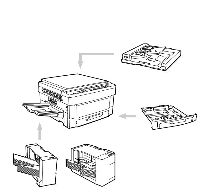
2. System configuration (options)
Automatic document feeder SF-A18
Tray (reserve) SF-UB15
Exclusive-use desk
SF-DS17
10-bin sorter SF-S17 N |
10-bin staple sorter SF-S54 |
|
Note: When installing the SF-S54, the exclusive-use desk (SF-DS17) is reguired.
1 – 1
[2] PRODUCT SPECIFICATIONS
1. Basic specifications
(1)Type: Table top
(2)Copy speed:
|
Normal |
Enlargement |
Reduction |
|
(Magnification) |
(Magnification) |
|
|
|
||
|
|
|
|
A3 |
10 sheets/min |
10 sheets/min |
10 sheets/min |
|
|
(200%) |
(50%) |
|
|
|
|
B4 |
12 sheets/min |
12 sheets/min |
12 sheets/min |
|
|
|
|
A4 (Portrait) |
18 sheets/min |
14 sheets/min |
14 sheets/min |
|
|
|
|
A4 (Landscape) |
14 sheets/min |
14 sheets/min |
14 sheets/min |
|
|
|
|
81⁄2 × 13" |
12 sheets/min |
12 sheets/min |
12 sheets/min |
(Note) The copy speeds for enlargement and reduction are minimum speed values.
(3)Warm up time: 35 sec or less
(4)First copy time: 5.3 sec (Tray)
(5)Jam recovery time: 8 sec (Conditions: After leaving the door
|
|
open for 60 sec, the standard conditions) |
|||
(6) |
Multi copy Max. 250 sheets |
|
|
||
(7) |
Original |
|
|
||
|
|
|
|
|
|
|
|
Max. original size |
|
A3 |
|
|
|
|
|
|
|
|
|
Reference original size |
|
Left side/Center |
|
|
|
|
|
|
|
|
|
Original sensing |
|
No |
|
|
|
|
|
|
|
(8) |
Copy magnification ratio |
|
|
||
Fixed magnification: AB series: 200, 141, 122, 115, 100, 86, 81,
70, 50% (9 steps)
Zoom range: 50% 200% (151 steps by the increment of 1%)
(9)Exposure
Exposure mode: Auto/Manual/Photo No. of manual steps: 9 steps
(10)Void width
Void area: Lead edge/rear edge: 3mm or less
Image loss Normal: 4mm or less
(11)Paper exit/finishing
Paper exit tray capacity: 250 sheets
Finishing: option 10-bin sorter, 10-bin staple sorter
(12) Additional functions
|
|
|
Function |
|
Remark |
||
|
|
|
|
|
|
|
|
Auto Paper Selection |
|
× |
|
|
|
||
Auto Magnification ratio |
|
× |
|
|
|
||
Selection |
|
|
|
|
|
||
|
|
|
|
|
|
||
|
|
|
|
|
|
|
|
Shift |
|
|
F |
|
|
|
|
|
|
|
|
|
|
|
|
1-set 2-copy |
|
|
F |
|
Enlargement is impossible. |
||
|
|
|
|
|
|
|
|
Edge erase |
|
|
F |
|
|
|
|
|
|
|
|
|
|
|
|
Built-in auditor |
|
|
F |
|
20 departments |
||
password mode |
|
|
|
||||
|
|
|
|
|
|
||
|
|
|
|
|
|
|
|
Interruption |
|
|
F |
|
|
|
|
|
|
|
|
|
|
|
|
Monochrom |
|
|
× |
|
|
|
|
|
|
|
|
|
|
|
|
AICS |
|
|
F |
|
|
|
|
|
|
|
|
|
|
|
|
Pre-heat mode |
|
|
F |
|
|
|
|
|
|
|
|
|
|
|
|
Auto shut off |
|
|
F |
|
|
|
|
|
|
|
|
|
|
|
|
Auto power save |
|
|
F |
|
|
|
|
|
|
|
|
|
|
|
|
Auto tray switching |
|
|
× |
|
|
|
|
|
|
|
|
|
|
|
|
Cover insertion |
|
|
× |
|
|
|
|
OHP insertion paper |
|
× |
|
|
|
||
Overlay |
|
|
× |
|
|
|
|
|
|
|
|
|
|
|
|
(13) External dimensions |
|
|
|
|
|||
|
|
|
|
|
|
|
|
|
W x D x H |
|
|
|
600 × 595 × 365 mm |
|
|
|
|
|
|
|
|
||
|
Occupying area (W x D) |
|
|
885 × 595 mm |
|
||
|
|
|
|
|
|
|
|
|
Weight |
|
|
|
|
41.0Kg |
|
|
|
|
|
|
|
|
|
(14) Power source |
|
|
|
|
|
|
|
Voltage: 220 230V 50/60Hz |
|
|
|
||||
|
240V 50Hz |
|
|
|
|
||
Frequency: 50/60Hz common |
|
|
|
||||
(15) Power consumption |
|
|
|
|
|||
|
|
|
|
|
|||
Max. power |
1.5kw |
|
|
(Note) Max. when the |
|||
consumption |
|
|
|
|
option is installed |
||
|
|
|
|
|
|||
Energy efficiency |
64Wh/h or less |
|
|
|
|||
|
|
|
|
|
|
||
Auto power shut |
5W or less |
|
|
|
|
||
off (for EPA) |
|
|
|
|
|
|
|
|
|
|
|
|
|
|
|
2 – 1
2. Description of each section
(1)Paper feed section
|
|
Copying size |
|
A3 A6 |
|
|||
|
|
|
|
|
|
|
|
|
|
|
Paper feed system |
|
1 tray + multi manual feed |
|
|||
|
|
|
|
|
|
|
|
|
|
|
Paper feed capacity |
|
250 sheets 1 |
|
|||
|
|
|
|
|
|
|
|
|
|
|
|
|
|
|
|||
Cassette |
Paper size |
|
Paper weight |
Paper kind |
||||
|
|
|
|
|
|
|
|
|
|
|
|
|
AB series: A3 |
|
|
Standard paper, |
|
Tray |
|
|
A5 |
|
56 80g/m2 |
|||
|
|
|
recycled paper |
|||||
|
|
|
|
Ledger Invoice |
|
|
||
|
|
|
|
|
|
|
|
|
|
|
|
|
|
|
|
|
|
|
|
|
|
AB series: A3 |
|
|
Standard paper, |
|
Multi |
|
Multi |
A6R |
|
56 80g/m2 |
specified paper, |
||
|
|
Ledger Invoice |
|
|
special paper, |
|||
manual |
|
|
|
|||||
|
|
|
|
OHP film, Second |
||||
paper |
|
|
|
|
|
|||
|
|
AB series: A3 |
|
52 |
original paper, |
|||
feed |
|
Single |
|
|||||
|
|
postcards |
||||||
|
|
|
A6R |
|
128g/m2 |
|||
|
|
|
|
|
|
|
(without folding) |
|
|
|
|
|
|
|
|
|
|
(2)Optical section
Light source |
Halogen lamp |
|
|||
|
|
|
|
||
Exposure system |
Slit exposure by moving the light source |
||||
|
|
|
|
||
Zooming system |
By changing the lens positions and the scan |
||||
|
|
speed. |
|
||
|
|
|
|
|
|
Lens |
Fixed focus lens |
|
|||
|
|
|
|
|
|
(3) |
Process |
|
|
|
|
|
|
|
|
||
Charging system |
|
(–) DC saw teeth electrode system |
|||
|
|
|
|
||
Transfer system |
|
(–) tungsten system |
|||
|
|
|
|
||
Separation system |
|
(AC) separation tungsten system |
|||
|
|
|
|
|
|
(4) |
Developing section |
|
|||
|
|
|
|
||
Developing system |
|
Dry, two-component magnetic brush |
|||
|
|
|
development (developer replacement) |
||
|
|
|
|
||
Developing bias voltage |
DC–200V ±5V |
|
|||
|
|
|
|
|
|
(5) |
Fusing section |
|
|
|
|
|
|
|
|
|
|
Fusing system |
|
|
|
Heat roller system |
|
|
|
|
|||
Upper heat roller surface temperature |
|
190 degrees C |
|||
|
|
|
|
|
|
Heater lamp |
|
|
|
Halogen lamp 1000W 1 |
|
|
|
|
|
|
|
3. Supply parts
|
Name |
Content |
|
Life |
Product name |
|
|
|
|
|
|
1 |
Photoconductor kit |
Photoconductor drum |
x 1 |
60K |
SF-226DR |
|
|
Cleaner blade |
x 1 |
|
|
|
|
Drum separation pawl |
x 2 |
|
|
|
|
|
|
|
|
2 |
Black developer |
Black developer (530g) |
x 10 |
60K x 10 |
SF-226CD |
|
|
|
|
|
|
3 |
Black toner |
Black toner bottle (280g) |
x 10 |
6K x 10 |
SF-126CT |
|
|
|
|
|
|
4 |
Upper heat roller kit |
Upper heat roller |
x 1 |
120K |
SF-216HU |
|
|
Upper separation pawl |
x 4 |
|
|
|
|
Fusing bearing |
x 1 |
|
|
|
|
|
|
|
|
5 |
Lower heat roller kit |
Lower heat roller |
x 1 |
120K |
SF-220LH |
|
|
Lower separation pawl |
x 4 |
|
|
|
|
|
|
|
|
6 |
Staple cartridge |
Staple cartridge (For SF-S54) |
x 3 |
5K staples x 3 |
SF-LS12 |
|
|
|
|
|
|
7 |
Upper heat roller |
Upper heat roller |
x 1 |
120K |
SF-216HU |
|
|
|
|
|
|
8 |
Upper separation pawl |
Upper separation pawl x 4 |
x 10 |
120K x 10 |
SF-216UP |
|
|
|
|
|
|
9 |
Heat roller gear |
Heat roller gear |
x 10 |
120K x 10 |
SF-216HG |
|
|
|
|
|
|
10 |
Lower heat roller |
Lower heat roller |
x 1 |
120K |
SF-216HR |
|
|
|
|
|
|
11 |
Lower separation pawl |
Lower separation pawl x 4 |
x 10 |
120K x 10 |
SF-216LP |
|
|
|
|
|
|
12 |
Screen grid |
Screen grid |
x 10 |
120K x 10 |
SF-216SU |
|
|
|
|
|
|
13 |
Cleaner blade |
Cleaner blade |
x 10 |
6K x 10 |
SF-216CB |
|
|
|
|
|
|
14 |
Charging plate |
Charging plate |
x 10 |
120K x 10 |
SF-216PU |
|
|
|
|
|
|
15 |
Ozone filter |
Ozone filter |
x 10 |
300K x 10 |
SF-216FL |
|
|
|
|
|
|
16 |
Copy lamp |
Copy lamp |
x 10 |
— |
SF-216CL |
|
|
|
|
|
|
17 |
MC case unit |
MC case unit |
x 10 |
— |
SF-216MC |
|
|
|
|
|
|
2 – 2
4. Optional specifications
(1) Automatic document feeder (ADF) <Model name: SF-A18>
Original set direction |
Face up |
|
|
Original set position |
Center reference |
|
|
Original transport system |
Belt (half size) system |
|
|
Original feed sequence |
Bottom taking (Face up exit) |
|
|
|
|
Original size |
A3 A5 |
|
|
Original change speed |
16 sheets/min |
(S → S) |
|
|
|
Original weight |
50 128g/m2 |
|
|
Original set quantity |
50 sheets, 50 ~ 80 g/cm2, |
|
80 ~ 128 g/m2 thickness max. 5 mm |
|
|
Original stop system |
Position control system |
|
|
Dimensions |
571 (W) x 521 (D) x 110 (H) (mm) |
|
(Height: excluding the tray) |
|
|
|
|
Weight |
About 11.5kg |
|
|
|
|
Power source |
Supplied from the copier's power section. |
|
|
Power consumption |
65W |
Functions
Original sensing on |
YES (Scanning read for uncertain size |
the tray |
originals.) |
|
|
Sensing size |
AB series: A3, B4, A4, A4R, A5 |
|
|
Original mixture |
Allowed (However, no linkage with the AMS) |
|
|
Original reverse |
NO |
(2) 10-bin sorter
<Model name: SF-S17 N>
Type |
|
Copier installation type/Hanging type |
||
|
|
|
|
|
|
|
|
|
|
Distribution system |
Bin shift by lead screw |
|||
|
|
|
|
|
|
|
|
|
|
No. of bins |
|
10 bins (The top bin is used also for |
||
|
|
|
non-sort.) |
|
|
|
|
|
|
|
|
|
|
|
Capacity |
|
30 sheets/bin A4, 100 sheets for the |
||
|
|
|
top bin only. |
|
|
|
|
|
|
Sorting |
|
30 sheets (A4) |
||
|
|
|
|
|
|
|
|
15 sheets (B4) |
|
|
|
|
|
|
|
|
|
15 sheets (A3) |
|
|
|
|
|
|
Grouping |
|
20 sheets (A4) |
||
|
|
|
|
|
|
|
|
15 sheets (B4) |
|
|
|
|
|
|
|
|
|
15 sheets (A3) |
|
|
|
|
|
|
|
|
|
|
|
Paper size |
|
(Non-sort) |
|
A3 A6 (Postcard)R |
|
|
|
|
|
|
|
(Sort/group) |
A3 A5 |
|
|
|
|
|
|
|
|
|
||
Paper transport |
|
Center reference |
||
|
|
|
||
|
|
|
||
Paper reception |
|
Face up |
||
|
|
|
|
|
|
|
|
|
|
Paper weight |
|
(Non-sort) |
|
52 128g/m2 |
|
|
(Sort/group) |
56 80g/m2 |
|
|
|
|
||
Dimensions |
|
335 (W) x 493 (D) x 298 (H) (mm) |
||
|
|
|
(Width: Including the tray.) |
|
|
|
|
||
|
|
|
||
Weight |
|
8.6kg [9.8kg Including mounted fittings] |
||
|
|
|
||
|
|
|
||
Power source |
|
Supplied from the copier. DC24V (1.2A) |
||
|
|
|||
|
|
|||
Power consumption |
Max. 30W |
|||
|
|
|
|
|
2 – 3
(3) 10-bin staple sorter (10-bin SS) <Model name: SF-S54>
Type |
|
|
Copier installation type/hanging type |
||
|
|
|
|
|
|
|
|
|
|
|
|
Distribution system |
Bin shift system by lead screw |
||||
|
|
|
|
|
|
|
|
|
|
|
|
No. of bins |
|
|
10 bins (The top bin is commonly used |
||
|
|
|
|
for non-sort. |
|
|
|
|
|
|
|
|
|
|
|
|
|
Capacity |
|
|
30 sheets for each bin |
||
|
|
|
|
(A4, 80g/m2) |
|
|
|
|
|
100 sheets for the top bin |
|
|
|
|
|
|
|
|
|
|
|
|
|
Sort |
|
|
30 sheets (A4) |
||
|
|
|
|
|
|
|
|
|
|
15 sheets (B4) |
|
|
|
|
|
|
|
|
|
|
|
15 sheets (A3, 80g/m2) |
|
|
|
|
|
|
|
Grouping |
|
|
20 sheets (A4) |
||
|
|
|
|
|
|
|
|
|
|
15 sheets (B4) |
|
|
|
|
|
|
|
|
|
|
|
15 sheets (A3, 80g/m2) |
|
Staple sort |
|
|
30 sheets (A4) |
||
|
|
|
|
|
|
|
|
|
|
15 SHEETS (B4) |
|
|
|
|
|
|
|
|
|
|
|
15 sheets (A3, 80g/m2) |
|
|
|
|
|
|
|
Paper size |
|
Non-sort |
A3 A6R |
||
|
|
|
|
|
|
|
|
Sort/group |
A3 A5 |
||
|
|
|
|
|
|
|
|
Staple sort |
A3, B4, A4, A4R, B5 |
||
|
|
|
|
|
|
|
|
|
|
||
Alignment (Sorting) |
Max. shift 2mm (Alignment operation) |
||||
|
|
|
|
||
|
|
|
|
||
Paper transport |
Center reference |
||||
|
|
|
|
||
|
|
|
|
||
Paper loading |
Face up |
||||
|
|
|
|
|
|
|
|
|
|
|
|
Paper weight |
|
Non-sort |
|
49 128g/m2 |
|
|
|
|
Sort/group/staple sort |
56 80g/m2 |
|
|
|
|
|
||
Dimensions |
|
|
390(W) 542(D) 400(H)mm |
||
|
|
|
|
||
|
|
|
|
||
Weight |
|
|
About 11.5kg, 15kg [including the |
||
|
|
|
|
installation kit] |
|
|
|
||||
|
|
||||
Power source |
DC24V (1.5A) supplied from the copier. |
||||
|
|
||||
|
|
||||
Power consumption |
Max. 36W |
||||
|
|
|
|
|
|
Staple section
Type |
Copier stapler |
|
|
|
|
|
|
|
Stapling time |
1.8 sec |
|
|
|
|
|
|
|
No. of stapled sheets |
30 sheets (80g/m2) |
|
|
|
|
Binding reference |
Front reference |
|
|
|
|
|
|
|
Staple supply |
Cartridge (5,000 pcs.) |
|
|
|
|
|
|
|
Staple |
SF-LS12 |
|
|
|
|
|
|
|
No staple/no cartridge/ |
Available |
|
no stapler detection |
|
|
|
|
|
|
|
|
Staple jam detection |
|
Available |
|
|
|
|
|
|
Manual staple mode |
|
Available (excluding manual stapling) |
|
|
|
Note: When installing the SF-S54, the exclusive-use desk (SF-DS17) is required.
(4) Exclusive-use desk
SF-DS17
Dimensions |
570(W) 523(D) 520(H)mm |
|
|
|
|
Weight |
About 19.5kg |
|
|
|
|
Functions |
Caster |
Provided |
|
|
|
|
Adjuster |
None |
|
|
|
|
Door |
None |
|
|
|
2 – 4

[3] PRODUCT VIEWS
1. External view and internal structure
5 6
1
4
2
7
|
8 |
3 |
9 |
|
10 |
4
11 12
14 15
16
13
No. |
Name |
No. |
Name |
No. |
Name |
|
|
|
|
|
|
1 |
Original cover |
2 |
Original table |
3 |
Paper exit tray |
|
|
|
|
|
|
4 |
Grip |
5 |
Manual feed original guide |
6 |
Manual feed tray |
|
|
|
|
|
|
7 |
Operation panel |
8 |
Front cover |
9 |
Power switch |
|
|
|
|
|
|
F |
Paper tray |
G |
Developing unit grip |
H |
Toner hopper |
|
|
|
|
|
|
I |
Fusing unit |
J |
Developing unit lock lever |
K |
Release lever |
|
|
|
|
|
|
L |
Drum |
|
|
|
|
|
|
|
|
|
|
3 – 1
2. Operation panel
1 |
2 |
3 |
|
4 |
5 |
6 |
7 |
|
8 |
9 |
10 |
11 |
12 |
|
13 |
14 |
15 |
SORTER |
|
EXPOSURE |
PAPER SIZE |
|
|
81/2 x 51/2 |
11x 17 |
200% |
|
|
|
1 |
2 |
POWER SAVE |
AUDIT CLEAR |
||
SORT |
DUAL PAGE |
|
AUTO |
|
11 x 17 |
|
|
|
|
141% |
|
|
|
3 |
|
||
COPY |
|
|
|
|
81/2 x 11 11x17 |
129% |
|
|
|
|
|
|
|
||||
|
|
|
MANUAL |
81/2 x 14 |
|
|
81/2 x 51/2 |
81/2 x11 |
|
|
|
|
|
|
|
||
|
|
|
|
|
1 |
|
|
8/2 x 14 |
11x17 |
121% |
|
|
|
|
|
|
|
|
|
|
PHOTO |
8 /2 x 11 |
|
|
1 |
|
|
|
|
|
4 |
5 |
6 |
|
|
STAPLE |
MARGIN |
|
|
|
100% |
|
|
|
|
|
|||||||
SORT |
|
|
|
81/2 x 51/2 |
|
|
11x17 |
1 |
95% |
|
|
|
|
|
|
|
|
|
SHIFT |
|
|
|
81/2 x 11 R |
|
|
8 /2 x14 |
|
|
|
|
|
|
|
|
|
GROUP |
|
1 |
2 3 |
4 5 |
|
|
81/2 x14 |
81/2 x11 |
77% |
ZOOM INTERRUPT |
7 |
8 |
9 |
CA |
|||
|
|
|
|
11x17 |
81/2 x111 |
64% |
|
|
|
||||||||
|
|
|
|
|
EXTRA |
|
|
81/2 x11 |
8/2 x5 /2 |
|
% |
|
|
|
|
|
|
|
EDGE ERASE |
|
|
|
|
|
|
11x17 |
81/2 x51/2 |
50% |
|
|
0/ |
C |
|
|
|
|
|
LIGHT |
DARK |
TRAY SELECT |
|
|
|
|
|
|
|
|
|
||||
|
|
|
|
|
|
|
|
|
|
|
|
|
|
||||
|
16 |
|
17 |
|
18 |
19 |
|
20 |
21 22 |
23 |
24 |
25 |
26 |
27 |
28 |
||
No. |
Name |
No. |
Name |
No. |
Name |
|
|
|
|
|
|
1 |
SORTER key and indicators |
2 |
DUAL PAGE COPY key and indicator |
3 |
MARGIN SHIFT key and indicator |
|
|
|
|
|
|
4 |
AUTO/MANUAL/PHOTO key and |
5 |
PAPER SIZE indicators |
6 |
Misfeed indicator |
|
indicators |
|
|
|
|
|
|
|
|
|
|
7 |
Paper feed location/misfeed location |
8 |
Preset ratio indicators |
9 |
Copy quantity display |
|
indicators |
|
|
|
|
|
|
|
|
|
|
F |
Maintenance required indicator |
G |
Developer replacement required |
H |
Toner required indicator |
|
|
|
indicator |
|
|
|
|
|
|
|
|
I |
10-key pad |
J |
POWER SAVE indicator |
K |
AUDIT CLEAR key |
|
|
|
|
|
|
L |
EDGE ERASE key and indicator |
M |
LIGHT and DARK keys and indicators |
N |
TRAY SELECT key |
|
|
|
|
|
|
O |
Paper required indicator |
P |
Copy ratio selector keys |
Q |
ZOOM indicator |
|
|
|
|
|
|
R |
Copy ratio display key |
S |
Zoom keys |
T |
INTERRUPT key and indicator |
|
|
|
|
|
|
U |
Zero/readout key |
V |
Clear key |
W |
Print button and READY indicator |
|
|
|
|
|
|
X |
Clear all key |
|
|
|
|
|
|
|
|
|
|
3 – 2
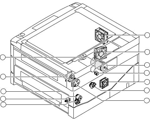
3. Clutches, solenoids, and motors
|
6 |
|
8 |
9 |
|
|
7 |
11 |
1 |
|
|
|
12 |
3 |
2 |
|
|
5 |
10 |
|
|
4 |
|
Clutches and solenoids
No. |
Signal name |
Name |
Functions, operations |
|
|
|
|
1 |
PSPS |
Paper separation solenoid |
Paper separation solenoid drive |
|
|
|
|
2 |
RRC |
Resist roller clutch |
For resist roller rotation |
|
|
|
|
3 |
TRC |
Transport roller clutch |
For transport roller rotation |
|
|
|
|
4 |
CPFC1 |
Tray paper feed clutch |
For paper feed roller rotation |
|
|
|
|
5 |
MPFS |
Manual paper feed solenoid |
For pressing take-up roller |
|
|
|
|
Motors
No. |
Signal name |
Name |
Functions, operations |
Type |
|
|
|
|
|
6 |
VFM |
Ventilation fan motor |
Used to ventilate around the fusing section, cools |
DC brushless |
|
|
|
down the machine, and remove ozone. |
|
|
|
|
|
|
7 |
MM |
Main motor |
Used to drive the body. |
DC brush |
|
|
|
|
|
8 |
CFM |
Optical system cooling fan |
Used to cool and ventilate the optical system. |
DC brushless |
|
|
|
|
|
9 |
LM |
Lens motor |
Used to move the optical lens. |
DC stepping |
|
|
|
|
|
F |
TM |
Toner motor |
Used to stir toner. |
DC synchronous |
|
|
|
|
|
G |
MRM |
Mirror motor |
Used to move the mirror base. |
DC stepping |
|
|
|
|
|
H |
SMF |
Suction fan motor |
Used to ventilate the suction section. |
DC brushless |
|
|
|
|
|
3 – 3

4. PWB
15 |
1 |
2 |
3 |
4 |
5 |
14 |
|
16 |
6 |
7 |
|
|
11 |
|
|
8 |
13 |
|
12 |
|
10 |
9 |
No |
Name |
Description |
No |
Name |
Description |
|
|
|
|
|
|
1 |
Operation PWB A |
Operation input, display control |
2 |
Operation PWB B |
Operation input, display control |
|
|
|
|
|
|
3 |
Blank lamp PWB |
Used to control the blank lamp. |
4 |
DL PWB |
Used to drive the discharge lamp. |
|
|
|
|
|
|
5 |
Optical PWB |
AE sensor and lens motor interface |
6 |
Process control PWB |
Used to sense the toner density. |
|
|
|
|
|
|
7 |
Main PWB |
Used to control the body. |
8 |
AC circuit PWB |
AC power input |
|
|
|
|
|
|
9 |
CSD PWB |
Used to sense the body cassette |
F |
DC circuit PWB |
DC power input |
|
|
size. |
|
|
|
|
|
|
|
|
|
G |
PID PWB |
Manual paper entry detection |
H |
PPD PWB |
Body PR roller JAM detection |
|
|
|
|
|
|
I |
High voltage PWB |
Process high voltage, developing |
J |
POD PWB |
Body paper exit section JAM |
|
|
bias voltage supply |
|
|
detection, ventilation fan motor |
|
|
|
|
|
interface |
|
|
|
|
|
|
K |
Mark sensor PWB |
Drum marking point detection |
L |
Sub DC power PWB |
Supplies power in the energy |
|
|
|
|
|
saving mode. (Supplies 5V to the |
|
|
|
|
|
main PWB and the operation |
|
|
|
|
|
PWB.) |
|
|
|
|
|
|
3 – 4
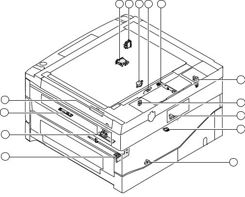
5. Sensors and switches
2 3 5 4 6
7
1
10
14 |
8 |
|
|
11 |
9 |
|
|
13 |
12 |
|
No. |
Signal name |
Name |
Type |
Operation, function |
|
|
|
|
|
1 |
TCS |
Toner density control sensor |
Transmission sensor |
HIGH when toner density falls. |
|
|
|
|
|
2 |
ILSW |
Front cabinet open/close switch |
Interlock switch |
ON when closed. |
|
|
|
|
|
3 |
MSW |
Power switch |
Seesaw switch |
|
|
|
|
|
|
4 |
TH |
Fusing heater thermistor |
Thermistor |
Greater resistance at low |
|
|
|
|
temperature |
|
|
|
|
|
5 |
TS |
Fusing heater thermostat |
Thermostat |
Contact open at abnormally high |
|
|
|
|
temperature |
|
|
|
|
|
6 |
POD |
Paper exit paper sensor |
Transmission photo sensor |
LOW when paper is present. |
|
|
|
|
|
7 |
MHPS |
Mirror home position sensor |
Transmission photo sensor |
HIGH when paper is sensed. |
|
|
|
|
|
8 |
MMRE |
Main motor encoder |
Transmission photo sensor |
Rotation pulse output |
|
|
|
|
|
9 |
TFD |
Waste toner full switch |
Lead switch |
HIGH when sensed. |
|
|
|
|
|
F |
LHPS |
Lens home position sensor |
Transmission photo sensor |
LOW when reduction. |
|
|
|
|
|
G |
PPD |
Paper transport sensor |
Transmission photo sensor |
LOW when paper is present. |
|
|
|
|
|
H |
PED1 |
Body upper tray paper presence detection |
Transmission photo sensor |
HIGH when paper is present. |
|
|
|
|
|
I |
DPPD1 |
Body upper tray paper transport sensor |
Transmission photo sensor |
LOW when paper is present. |
|
|
|
|
|
J |
PID |
Single manual feed paper entry sensor |
Transmission photo sensor |
HIGH when paper is present. |
|
|
|
|
|
3 – 5
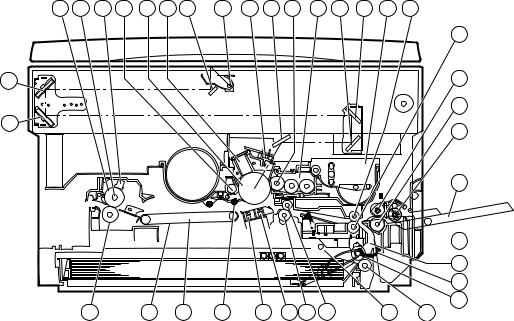
6. Rollers, mirrors, etc.
30 |
29 |
28 |
20 |
19 |
18 |
3 |
4 |
17 |
7 |
34 |
16 |
6 |
5 |
8 |
14 |
|
|
|
|
|
|
|
|
|
|
|
|
|
|
|
15 |
2 |
|
|
|
|
|
|
|
|
|
|
|
|
|
|
12 |
|
|
|
|
|
|
|
|
|
|
|
|
|
|
|
13 |
1 |
|
|
|
|
|
|
|
|
|
|
|
|
|
|
11 |
|
|
|
|
|
|
|
|
|
|
|
|
|
|
|
|
|
|
|
|
|
|
|
|
|
|
|
|
|
|
|
9 |


 32 33
32 33
38
35
31 |
27 |
26 |
25 |
24 |
23 22 |
21 |
37 |
36 |
No. |
Name |
No. |
Name |
No. |
Name |
|
|
|
|
|
|
1 |
No. 3 mirror |
2 |
No. 2 mirror |
3 |
No. 1 mirror |
|
|
|
|
|
|
4 |
Copy lamp |
5 |
No. 4 mirror |
6 |
No. 5 mirror |
|
|
|
|
|
|
7 |
No. 6 mirror |
8 |
Developing unit toner box |
9 |
Manual tray |
|
|
|
|
|
|
F |
— |
G |
Take-up roller |
H |
Paper feed roller |
|
|
|
|
|
|
I |
Reverse roller |
J |
PS front roller follower roll |
K |
PS front roller |
|
|
|
|
|
|
L |
Developing unit |
M |
Blank lamp |
N |
Main charger unit |
|
|
|
|
|
|
O |
Photoconductor drum |
P |
Cleaner unit |
Q |
Resist roller follower roll |
|
|
|
|
|
|
R |
Resist roller |
S |
Transfer charger |
T |
Separation charger |
|
|
|
|
|
|
U |
Drum separation pawl |
V |
Suction unit |
W |
Suction belt |
|
|
|
|
|
|
X |
Fusing thermistor |
Y |
Heater lamp |
Z |
Upper heat roller |
|
|
|
|
|
|
[ |
Lower heat roller |
\ |
Transport roller (upper) follower roller |
] |
Transport roller (upper) |
|
|
|
|
|
|
^ |
Developing magnet roller |
_ |
Tray paper feed roller |
` |
Tray paper feed reverse roller |
|
|
|
|
|
|
a |
Tray paper feed take-up roller |
b |
PE actuator |
|
|
|
|
|
|
|
|
|
|
|
|
|
|
3 – 6
[4] UNPACKING AND INSTALLATION
1. Unpacking
Packing material/accessory list
|
Name |
Q'ty |
|
|
|
1 |
Paper exit tray |
1 |
|
|
|
2 |
Instruction manual |
1 |
|
|
|
3 |
Maintenance card |
1 |
|
|
|
4 |
Dust cover |
1 |
|
|
|
5 |
Service contract |
1 |
|
|
|
6 |
Installation manual |
1 |
|
|
|
7 |
Magnification ratio select label |
1 |
|
|
|
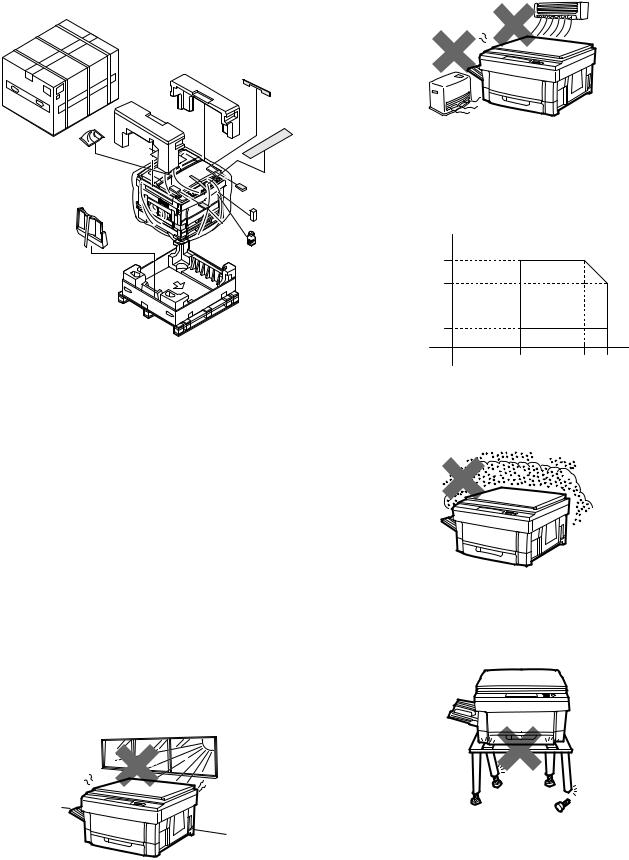
2. Installation
Installing conditions
The surrounding conditions of the machine affect the machine performance greatly. Use great care for the following items.
(1) Environment
1Avoid direct sunlight, and avoid installation near the window. (Curtains or blinds must be shut completely.)
If not, the plastic parts and the original cover may be deformed. Even if the window is of frosted glass, there is no difference.
2Avoid high temperature and high humidity, and avoid sudden temperature change. (Avoid installation near a cooler or a heater.)
If not, paper absorbs moisture and dew forms in the machine, causing paper jam or degraded image quality.
(Standard condition): The best condition to use the machine. 20 25°C: 65 ±5%RH
(Temperature and humidity): 15 30°C 20% 85% RH 35°C for 65%
% HR
85 |
|
|
|
65 |
|
|
|
Humidity |
|
|
|
20 |
|
|
|
15 |
30 |
35 |
˚C |
3Avoid dust and vibrations.
If dust enters the machine, malfunctions may occur.
4Avoid installation on an unstable surface.
Keep the machine in level state to maintain the performance.
4 – 1
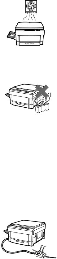
5 Avoid installation to a poorly ventilated place.
6Avoid installation to a place where there are flammable materials or ammonia gas, etc. If the machine is installed near a diazo copier, the picture quality may be degraded and malfunctions may occur.
7 Install near a power outlet.
(2) Space around the machine
Install the machine with its rear side about 10cm (6 inches) apart from the wall in order to allow space to ventilation by the cooling fan.
Also allow enough space around the machine for proper operation.
(3) Installation base
Set the machine in horizontal position in the following procedure.
Be sure to use a leveling instrument (UKOGM0054CSZZ) to install the machine on a flat, horizontal place.
(Note) If the machine is not in horizontal position, the toner density control function may not work normally, resulting in degraded picture quality.
(4) Power source
1 Use the power source of the rated capacity.
2Avoid complicated wiring. If not, the breaker or the fuse may be overloaded.
(5) Grounding wire connection
1 Connect the grounding wire to prevent against a danger.
2When connecting the grounding wire, connect only to the grounding object (the grounding terminal of the power outlet, etc.) and never connect to a gas pipe.
4 – 2
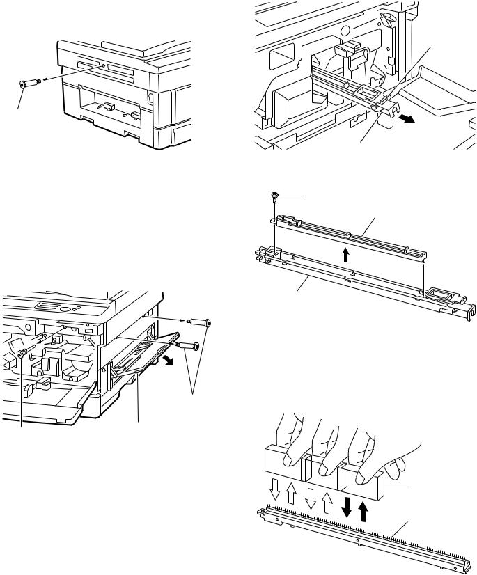
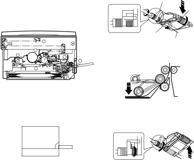
3. Optical system lock release
A. No. 2/3 mirror unit lock release
Remove the one fixing screw of the No. 2/3 mirror unit on the left side of the copier.
Mirror unit fixing screw
B. Lens and No. 4/5 mirror unit lock release
Remove two fixing screws of the No. 4/5 mirror unit on the right inside of the copier.
Open the front cabinet and remove one fixing screw of the lens on the lower side of the operation panel.
Mirror unit fixing screw
Paper feed tray
Lens fixing screw
4. Charger cleaning
A. Main charger unit electrode cleaning
1Press the hook section of the main charger unit to release lock, and pull out and remove the main charger unit from the copier.
Hook
main charger unit
2Remove one fixing screw of the main charger unit (on the back side).
Fixing screw
Electrode section
Main charger unit
3Press the electrode cleaner onto the tips of the electrode so that the tips are inserted into the cleaner a few times to clean.
(Note)
•Do not move the cleaner back and forth with the electrode tips inserted into it.
•When cleaning, clean thoroughly at one time. Avoid partial cleaning.
Electrode cleaner
Electrode section
4Return the electrode section to the original position and fix it with a screw.
4 – 3

5Insert the main charger unit along the guide groove in the copier fully to the bottom.
Main charger unit
5. Developing unit setting
A. Developing unit setting
1Open the front cabinet, remove the installation toner fixed to the developing unit level with tape, and pull the developing unit lever toward you.
2Hold the grip of the developing unit, and slowly pull out the developing unit until it stops.
Then hold the hand carry strap and press the developing lever, and remove the developing unit.
Hand carry strap
DV lever |
Developing unit |
Grip |
3Remove three fixing screws of the toner hopper of the developing unit, and remove the toner hopper.
Fixing screw
Fixing screw |
Toner hopper |
Developing unit
4While supplying developer from the developer supply port of the developing unit, turn the MG gear clockwise with a screwdriver or a scale to supply fully in the developing unit.
Developer
Developer supply port
Developing unit
MG gear
Screwdriver (+) or scale
5Install the toner hopper to the developing unit and fix it with two screws.
Fixing screw
Toner hopper
Fixing screw
Developing unit
4 – 4

6Hold the hand carry strap of the developing unit and insert it into the copier fully to the bottom.
Hand carry strap
Developing unit |
Grip |
|
7 Close the developing unit lever and close the front cabinet.
Developing unit lever
Front cabinet
With the above procedure, setting of the developing unit is completed.
6. Toner density sensor level adjustment
Turn on the copier power switch.
A. Developing unit level adjustment
1 Execute simulation 25.
C |
0 |
2 |
|
5 |
2 |
2 After 3 minutes, simulation 25 is completed.
(Note) If the simulation is terminated halfway, automatic reading is not performed. Do not terminate it halfway.
3 Cancel simulation 25 with the CA key.
7. Accessory installation
A. Copier tray installation
Install the copy tray to the paper exit section on the left side of the copier.
Copy tray
8. Toner supply
1 Open the front cover.
2Pull down the developer unit lock lever and pull the developer unit out slowly unit it stops.
4 – 5
3 Hold the new toner bottle as shown and shake it four or five times.
4 Open the toner hopper cover.
5 Pour the toner evenly into the toner hopper.
6 Close the toner hopper cover.
7 Slide the developer unit into the copier.
8 Return the developer unit lock lever into place.
9 Close the front cover.
4 – 6
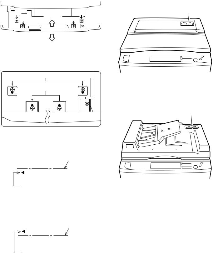
9. Center shift adjustment
There is basically no need to perform the center shift adjustment because it is made when shipping. If the center should be shifted, adjust in the following procedures.
Make a copy. If the center is shifted as shown in Fig. 1 or Fig. 2, loosen the four screws which are fixing the cassette grip cabinet.
Section b |
Section b |
Section a |
Direction A |
Section a |
Direction B
(Note) When fixing the cassette cabinet, the fixing screws and the cabinet clearance a and b are in symmetry.
[Reference figure]
Section b
Section a
(1) Fig. 1
Move the cassette grip cabinet in direction A, tighten two fixing screws (a) and tow fixing screws (b) in this sequence. Make a copy again and check the center.
[Fig.1] |
|
Paper center line |
|
|
|
Image center line (First image)
(2) Fig. 2
Move the cassette grip cabinet in direction B, tighten two fixing screws (a) and tow fixing screws (b) in this sequence. Make a copy again and check the center.
[Fig.2] |
|
Paper center line |
|
|
|
Image center line (First image)
10. Label attachment
A. Label attachment
Attach the magnification ratio select label packed together with the Operation manual to the position shown in the figure below.
• When attaching the label to the copier with the original cover.
Magnification ratio select lable
•When attaching the label to the optional automatic original feeder
(SF-A18)
Magnification ratio select lable
4 – 7
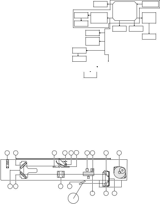
[5] DESCRIPTIONS OF EACH SECTION
Descriptions are made on the following sections:
1 Paper feed section
2 Developing section
3 Optical section
4 Process section
5 Separation/transport section
6 Fusing/paper exit section
7 High voltage section
3
4
6
2
1
5
1. Paper feed section
1) General descriptions
To realize the compact design, the front loading system and the foldable multi paper feed unit (Option for some areas) are employed.
50 Sheets
250 sheets
The paper feed tray is of the universal type and has capacity of 250 sheets. The front loading system allows the tray to be loaded from the lower side of the front cabinet.
Manual paper feed is made in the multi paper feed.
2) Basic operations
(Tray paper feed operation)
When the CPFC (Cassette paper feed clutch) turn on, the paper feed roller shaft, the paper feed roller, and the take-up roller rotate in the direction of A. At the same time, the limiter spring moves down the roller release arm. As a result, the take-up roller falls by its own weight onto the paper surface, starting paper feed.
Roller release arm
Take-up roller
Paper feed roller
Paper feed roller shaft
When the CPFC turns off, rotation stops and the take-up roller is pushed up to the original position by the roller release arm spring.
(Manual paper feed operation)
There is no special mechanism for manual paper feed other than the manual feed paper sensing actuator and the paper guide.
When the CPFC turns off, rotation stops and the take-up roller is pushed up to the original position.
5 – 1

2. Developing section
1) General descriptions
(1) Two-component developer
The developer is composed of toner and carrier.
Carrier serves as a medium for attaching toner onto the electrostatic image on the photoconductor drum.
By stirring toner and carrier, they are rubbed to be charged positive
(+) and negative (–) respectively.
Since developer will deteriorate to degrade copy quality, it should be replaced regularly.
(2) Two-component magnetic brush development
The rotatable non-magnetic sleeve is provided over the magnet roller and is rotated.
Carrier forms a magnetic brush on the sleeve surface by magnetic force to attach toner onto the electrostatic image on the photoconductor drum.
(3) Developing bias
When the photoconductor is charged and exposed to light (exposure), the surface potential (voltage) of the photoconductor will not be lost completely. (The residual potential remains.)
Toner is attracted to the photoconductor by this residual potential, dirtying the photoconductor. As a result, a dirty copy of white background is generated.
To prevent against this, a voltage of the same polarity and higher than the residual potential is applied to the MG roller, preventing toner from being attached to the photoconductor surface.
Residual potential < DV BIAS
MG roller
DV BIAS
-200V
 Toner
Toner  Carrier
Developing bias voltage
(4) DV harness
The toner density sensor, the developing bias, harness.
(For details, refer to [6] DISASSEMBLY AND ASSEMBLY.)
(Viewed from the rear of develoing unit)
DV harness connector
(Details of DV harness connector)
For bias
GND
GND
*For toner density sensor
VB
*Resistance value is identified by color
2) Basic composition
2 |
4 |
1
|
3 |
5 |
|
|
|
|
|
|
|
|
|
No. |
Name |
|
|
|
|
|
|
|
|||
1 |
Magnet roller |
Forms a magnetic brush of carrier |
|||
|
|
by magnetic force. |
|
|
|
|
|
|
|||
2 |
Developing doctor blade |
Limits the height of the magnetic |
|||
|
|
brush. |
|
|
|
|
|
|
|||
3 |
Developing MIX roller |
Stirs carrier in the developing unit |
|||
|
|
and distributes toner evenly. |
|
||
|
|
|
|||
4 |
Toner transport roller |
Transport toner sent from the |
|||
|
|
toner hopper unit to the stirring |
|||
|
|
section. |
|
|
|
|
|
|
|
|
|
5 |
Toner density sensor |
Senses |
toner |
density |
in |
|
|
developer. |
|
|
|
|
|
|
|
|
|
5 – 2
3) Basic operations
(Cassette paper feed)
When the CPFC (cassette paper feed clutch) is turned on, the paper feed roller shaft, the paper feed roller, and the take-up roller rotates in the direction of A, and the roller release arm is moved downward by the limiter spring. As a result, the take-up roller falls by its weight to reach the paper surface, feeding the paper. When the CPFC is turned off, the take-up roller is pushed up to the position by the roller release arm spring.
Proccess |
Main motor |
|
unit |
||
|
||
Main drive unit |
||
Stirring roller |
|
|
DV drive unit |
Fuser unit |
|
MG roller |
|
|
Cleaner |
Transport |
|
unit |
unit |
|
PS roller |
Paper exit |
|
|
||
Multi manual |
roller |
|
|
||
insertion paper |
|
|
feed unit |
|
|
(Option) |
|
|
Transport |
|
|
roller(upper) |
|
|
Transport roller(lower)
|
|
|
Paper feed |
Paper feed |
|
||
|
rive unit |
||
unit |
|
||
|
|
||
|
|
|
|
Paper feed unit
3. Optical section
1) General description
•The optical section of this model is composed of the fixed focus lens and six mirrors. Since the fixed focus lens is used, No. 4/5 mirror base is shifted according to the shift of the lens to change the distance between the original and the drum (OID, Original
Image Distance) in reduction or enlargement copy.
The lens and No. 4/5 mirror unit are shifted by driving the stepping motor with the signals from the main control PWB, allowing zooming of 151 steps in 1% increment in the range of 0.50 to 2.00.
•Exposure is adjusted by changing the copy lamp voltage. The AE sensor is provided in the zoom base to sense the density of the original.
The copy lamp light is reflected by the original to the AE sensor, which senses the density of the original and adjust the copy lamp light quantity according to the density.
•The exposure system is the slit exposure system by moving light source.
16 |
4 |
11 |
1 |
2 |
3 |
17 |
15 |
7 |
13 |
10 |
5 |
6 |
|
9 |
|
|
|
|
|
|
|
|
|
|
|
|
14 |
8 |
12 |
1 |
Copy lamp |
2 |
Reflector |
3 |
No. 1 mirror |
|
|
|
|
|
|
4 |
No. 2 mirror |
5 |
No. 3 mirror |
6 |
Lens |
|
|
|
|
|
|
7 |
No. 4 mirror |
8 |
No. 5 mirror |
9 |
No. 6 mirror |
|
|
|
|
|
|
F |
No. 2/3 mirror base unit |
G |
Copy lamp unit |
H |
No. 4/5 mirror base unit |
|
|
|
|
|
|
I |
Mirror motor |
J |
Lens/No. 4/5 mirror base drive motor |
K |
Lens home position sensor |
|
|
|
|
|
|
L |
Mirror home position sensor |
M |
Automatic exposure (AE) sensor/ |
|
|
|
|
|
Optical system dirt sensor |
|
|
|
|
|
|
|
|
5 – 3
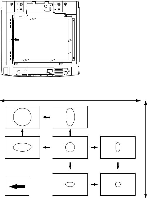
(1) Original table |
(2) Copy lamp |
|
The original table is fixed. The original is set in the left center position. |
200V series: 170V, 310W |
|
|
(3) Mirror |
|
|
This model uses six mirrors. |
|
|
No. 1 mirror is attached to the copy lamp unit, No. 2/3 mirrors are |
|
|
attached to No. 2/3 mirror base, No. 4/5 mirrors are attached to No. |
|
|
4/5 mirror base. |
|
|
The copy lamp unit and the No. 2/3 mirror base unit are scanned in |
|
|
copying. The No. 4/5 mirror base is shifted in zoom copying to |
|
|
change the distance between ten original and the drum. |
|
|
(4) Lens (fixed focus lens) |
|
|
• Construction (1 group 3 lenses) |
|
|
• |
Brightness (F8.5) |
|
• |
Focus: (195mm ±1%) |
(5) Lens home position sensor (LHPS)
This sensor senses the lens home position. The output signal of this sensor is the basic signal to control the copy magnification ratio.
(6) Lens base
The lens is mounted to the lens base, which is shifted toward the paper feed direction in reduction copy or toward the paper exit direction in enlargement copy by the lens drive motor.
Mirror base scan speed is changed for zooming
Enlargment
Normal
Zooming by changing the lens and mirror position
Original
Reduction
Copy direction
5 – 4

Parts identification and functions
Mirror home position sensor
No. 2/3 mirror unit Reflector Copy lamp unit
Lens drive wire
Lens home position sensor |
|
|
Mirror motor |
AE sensor |
Lens No. 4/5 mirror unit |
|
drive motor N |
Copy lamp
No. 4/5 mirror unit
Lens
Lens unit
|
|
|
|
|
|
|
|
|
|
|
|
|
|
|
|
|
|
|
|
|
|
|
|
|
|
|
|
|
|
|
|
|
|
|
|
|
|
|
|
|
|
|
|
|
|
|
|
|
|
|
|
|
|
|
|
|
|
|
|
|
|
|
|
|
|
|
|
|
|
|
|
|
|
|
|
|
|
|
|
|
|
|
|
|
|
|
|
|
|
|
|
|
|
|
|
|
|
|
|
|
|
|
|
|
|
|
|
|
|
|
|
|
|
|
|
|
|
|
|
|
|
|
|
|
|
|
|
|
|
|
|
|
|
|
|
|
|
|
|
|
|
|
|
|
|
|
Mirror base wire |
Temperature fuse |
|
|
|
|
|
|
|||||
(7) Lens drive shaft
This shaft controls the optical axis of the lens in zoom copy. The lens follows along the slide base shaft.
(8) Lens drive wire
This is to shift the lens unit and the No. 4/5 mirror base.
(9) No. 4/5 mirror unit
No. 4/5 mirrors are attached to this unit. It is shifted by the lens drive motor to change the distance between the original and the drum according to the zooming ratio.
(10) Mirror motor
This stepping motor shifts the copy lamp unit and the No. 2/3 mirror base. It is rotated at the rpm according to each zooming ratio.
(11) Mirror home position sensor (MHPS)
This sensor senses the home position of the copy lamp unit. It is of light transmission type.
(12) No. 2/3 mirror unit
No. 2/3 mirrors are attached to this unit. It is scanned by the mirror motor.
(13) Copy lamp unit
This is composed of No. 1 mirror, the temperature fuse, the copy lamp, the exposure adjustment plate, and the reflector, and scanned by the mirror motor.
(14) Temperature fuse
This is attached closely to the reflector to prevent against abnormal temperature rise in the optical system. If the temperature rises abnormally, it turns off the copy lamp power directly.
200V series (117°C)
(15) Reflector
Light from the copy lamp is reflected by the reflector to the original.
(16) Exposure adjustment plate
Four exposure adjustment plates are attached to the copy lamp unit to adjust exposure balance in back and forth direction of the frame.
(17) Mirror base drive wire
This wire transmits the mirror motor power to the copy lamp unit and the No. 2/3 mirror base to scan the mirror base.
(18) Lens drive motor
This stepping motor drives the lens and the No. 4/5 mirror base.
(19) AE sensor
This AE sensor senses the original density by the light emitted from the copy lamp and reflected by the original, controlling the developing bias. The photometric area is about 100m width at the center and in the mirror base scanning direction.
The element is photo diodes.
5 – 5
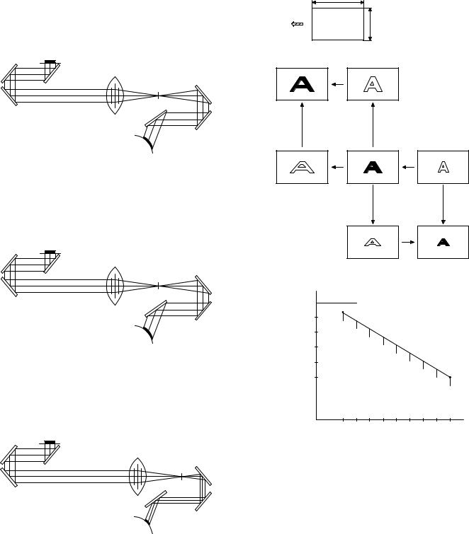
2) Basic operations
(Positions of the original, the lens, and the image in each magnification ratio)
Normal: The distance between the original set on the table glass and the lens is equal to the distance between the lens and the drum, resulting in the equal size of the original and the image.
Enlargement: Compared to the normal copy, the lens is nearer to the original and the distance between the original and the lens is shorter.
The distance between the No. 4/5 mirror unit and the lens is greater, and the distance between the lens and the drum is also greater.
The distance between the original and the exposure surface of the drum is greater than that in the normal copy.
Reduction: Compared to the normal copy, the lens is nearer to the drum, and the distance between the original surface and the lens is longer.
The distance between the lens and the exposure surface of the drum is shorter.
The distance between the No. 4/5 mirror unit and the lens is greater.
The distance between the original and the exposure surface of the drum is greater than that in the normal copy.
Mirror base scan speed
|
Lens and mirror positions |
Copy paper |
are changed to adjust the |
magnification ratio |
feed derection
Mirror scan speed is cahnged to adjust the magnification ratio Mirror scan speed Drum rotation speed<Mirror scan speed
Enlargement
Original
Reduction
(Copy lamp control in each copy density)
|
|
|
|
[MAX. 83V(166V)] |
|
|
80 |
|
|
|
|
|
70 |
|
|
|
|
CLV |
60 |
|
|
|
|
(Copy lamp |
|
|
|
|
|
50 |
|
|
|
|
|
application |
|
|
|
|
|
voltage) |
40 |
|
|
|
|
|
|
|
|
|
|
|
|
|
|
[MIN. 45V(90V)] |
|
|
(V) |
|
|
|
|
|
EX1 |
2 |
3 |
4 |
EX5 |
Execute Sim 46-01 to determine the copy lamp application voltage
(CLV) in EX1 and EX5.
Then divide the difference between the voltages of EX1.0 and EX5.0 into nine.
The application voltage of the copy lamp in each exposure level is determined by varying the ON timer duty of the copy lamp ON control signal.
•Photo density copy mode
Make the same control procedures as the manual density copy mode.
The image density is controlled by lowering the grid bias voltage of the charging charger. To maintain the reproduction quality in half tone, the ON time duty of the copy lamp ON signal is made shorter than in the manual density copy mode. (The application voltage is lower.)
5 – 6

(Optical system dirt correction)
This model perform dirt correction by changing the copy lamp intensity according to the dirt degree in the optical system (the copy lamp unit, No. 1 mirror, No.2 mirror, No.3 mirror) to prevent against remarkable degrading of copy quality.
The reference value is the AE sensor output value which is obtained when the reference plate is exposed with the copy lamp voltage of
67.0V (134.0V) at power ON.
This value is checked with sim 44-08, 09.
Reference plate (Glass holder) |
Table glass |
|
Copy lamp light quantity "UP"
Automatic exposure sensor
CPU Reference value >Measured value Correction data output
CLV |
|
|
|
|
|
Sim46 |
|
|
|
|
|
100 |
200 |
300 |
400 |
79.8K |
80K |
CLV + (0.7) |
|
|
|
|
|
(1) Setting the reference value for optical system correction. |
(2) Dirt correction |
|
||||||||
Reference plate (Glass holder) |
Table glass |
Reference plate (Glass holder) |
Table glass |
|||||||
|
|
|
|
|
|
|
|
|||
|
|
|
|
|
|
|
|
|
|
|
|
|
|
|
|
|
|
|
|
|
|
|
|
|
|
|
|
|
|
|
|
|
Automatic exposure sensor
CPU reference value setting
1 Clean the optical system at every maintenance.
2Perform Simulation 46-1.
(The previous data are cleared.)
3After completion of Simulation 46-1, when performing the first mirror initialization, measure light quantity of the copy lamp. Obtain the average value from the four measurement values and use the average value as the reference value for correction.
1234
 800ms
800ms
CL
Light quantity measurement
Obtain the average value of four AE sensor values, and store it.
Copy lamp light quantity "UP"
Automatic exposure sensor
CPU Reference value >Measured value Correction data output
1 Measure light quantity when performing mirror initialization.
2 Store the correction data into memory.
3 Reset the register inside the CPU.
5 – 7
4. Copy process
This model basic process and structure
•The Scorotron method is used to evenly charge the photoconductor surface to the given potential in the charge process. The corona wire regularly used is now replaced with a new corona charge mechanism that employs the 0.1mm thick stainless steel saw teeth plate, in order to suppress ozone generated when the oxide molecule in air is ionized.
•Considering the service efficiency, the process separation mechanism is adopted.
•To prevent high voltage leakage by the loose corona charge unit, a one-touch stopper mechanism is adopted.
Proccess |
Main motor |
|
unit |
||
|
||
Main drive unit |
||
Stirring roller |
|
|
DV drive unit |
Fuser unit |
|
MG roller |
|
|
Cleaner |
Transport |
|
unit |
unit |
|
PS roller |
Paper exit |
|
|
||
Multi manual |
roller |
|
|
||
insertion paper |
|
|
feed unit |
|
|
(Option) |
|
|
Transport |
|
|
roller(upper) |
|
|
Transport |
|
|
roller(lower) |
|
|
|
|
|
Paper feed |
Paper feed |
|
||
|
rive unit |
||
unit |
|
||
|
|
||
|
|
|
|
Paper feed unit
1) Photoconductor
•This model uses OPC (organic photoconductor) as photoconductive material. (φ50 mm)
OPC layer |
CTL (Electric charge moving layer) |
|
CGL (Electric charge generating layer) |
|
Aluminum layer |
5 – 8
 Loading...