


LC-30AA1M

1
Contents
Contents …………………………………………………… 1
Dear SHARP customer …………………………………… 2
Important Safety Precautions ………………………… 2
Supplied accessories …………………………………… 5
Preparation ………………………………………………… 6
Where to place the System…………………………… 6
Setting the System …………………………………… 7
Removing the stand and speaker …………………… 11
Setting the Display on the wall ……………………… 12
Setting the AVC System with the stand …………… 12
Inserting the batteries ………………………………… 13
Using the remote control unit ………………………… 13
Cautions regarding remote control unit ……… 13
Part names ………………………………………………… 14
Display ………………………………………………… 14
AVC System …………………………………………… 16
Remote control unit …………………………………… 17
Watching TV ……………………………………………… 18
Basic connection ……………………………………… 18
Connecting to an antenna ……………………… 18
Connecting to the power outlet ………………… 18
Turning on the power ………………………………… 19
Turning off the power ………………………………… 19
Simple button operations for changing channels … 20
Using Flashback (A) on the remote control unit … 20
Simple button operation for changing
volume/sound …………………………………… 21
Basic adjustment settings ……………………………… 24
AV input mode menu items …………………………… 24
PC input mode menu items ………………………… 24
Auto installation ……………………………………… 25
Programme setup……………………………………… 27
Auto search ……………………………………… 27
Manual setting for each channel ……………… 28
Search tuning………………………………… 29
Fine tuning …………………………………… 29
Colour system ……………………………… 30
Sound system (Broadcasting system) …… 30
Labelling channels ………………………… 30
Skipping channels ………………………… 31
Setting the child lock ……………………… 31
Sort ………………………………………………… 32
Booster …………………………………………… 33
Language setting for on-screen display …………… 34
Picture adjustments …………………………………… 35
C.M.S. (Colour Management System) ………… 36
Colour temperature ……………………………… 37
Black ……………………………………………… 37
Monochrome ……………………………………… 38
Film mode ………………………………………… 38
I/P setting ………………………………………… 39
DNR (Digital Noise Reduction) ………………… 39
Audio adjustment ……………………………………… 40
Sound adjustment ……………………………… 40
Dolby Virtual ……………………………………… 40
Power Control ………………………………………… 41
Power Control for AV source …………………… 41
Power Control for PC source …………………… 43
Using external equipment ……………………………… 44
Watching a DVD image ……………………………… 45
Connecting a DVD player ……………………… 45
Displaying a DVD image ………………………… 45
Watching a VCR image ……………………………… 46
Connecting a VCR ……………………………… 46
Displaying a VCR image ………………………… 46
Watching broadcasts via an HDTV tuner …………… 47
Connecting an HDTV tuner ……………………… 47
Displaying broadcasts via an HDTV tuner …… 47
Enjoying a game console and viewing camcorder
images …………………………………………… 48
Connecting a game console or camcorder …… 48
Displaying an image of the game console or
camcorder …………………………………… 48
Viewing an image from a PC ………………………… 49
Connecting a PC ………………………………… 49
Displaying an image from a PC ………………… 49
Connecting external speakers ……………………… 50
Selecting speakers ……………………………… 51
Useful adjustment settings ……………………………… 52
Image position (AV input mode only) ……………… 52
Moving the picture on the screen …………………… 53
Auto Sync. adjustment (PC input mode only) ……… 54
Fine Sync. adjustment (PC input mode only) ……… 54
Input signal source …………………………………… 55
Input Label …………………………………………… 56
Colour system setting (AV input mode only) ……… 57
AV mode selection …………………………………… 57
WIDE mode (for AV input mode) …………………… 58
WIDE mode (for PC input mode) …………………… 59
Input signal (PC input mode only) …………………… 60
Wide screen signalling (WSS)
(AV input mode only) …………………………… 61
Picture aspect ratio (AV input mode only) ………… 61
Selecting Full Mode display
(for AV input mode) (LC-30AA1M only) ……… 62
Rotate …………………………………………………… 63
Audio out ……………………………………………… 64
Sleep timer …………………………………………… 64
Cool climate …………………………………………… 65
Password setting for child lock (TV mode only) …… 66
Useful features …………………………………………… 67
Dual screen functions ………………………………… 67
Teletext language setting …………………………… 68
Teletext function ……………………………………… 69
Appendix ………………………………………………… 72
Troubleshooting ……………………………………… 72
PC compatibility chart ………………………………… 73
RS-232C port specifications ………………………… 74
Specifications ………………………………………… 76
Optional accessories ………………………………… 76
Dimensional drawings …………………………………… 77
LC-30AA1M
LC-37AA1M
LCD COLOUR TELEVISION
ENGLISH
OPERATION MANUAL
ENGLISH
LC-37AA1M(E)-a 03.11.6, 9:46 AM1
2
Important Safety Precautions
Electricity is used to perform many useful functions, but it can also cause personal injuries and property
damage if improperly handled. This product has been engineered and manufactured with the highest
priority on safety. However, improper use can result in electric shock and/or fire. In order to prevent potential
danger, please observe the following instructions when installing, operating and cleaning the product. To
ensure your safety and prolong the service life of your LCD colour TV product, please read the following
precautions carefully before using the product.
1. Read instructions—All operating instructions must be read and understood before the product is operated.
2. Keep this manual in a safe place—These safety and operating instructions must be kept in a safe place for
future reference.
3. Observe warnings—All warnings on the product and in the instructions must be observed closely.
4. Follow instructions—All operating instructions must be followed.
5. Attachments—Do not use attachments not recommended by the manufacturer. Use of inadequate attachments
can result in accidents.
6. Power source—This product must operate on a power source specified on the specification label. If you are
not sure of the type of power supply used in your home, consult your dealer or local power company.
7. AC cord protection—The AC cords must be routed properly to prevent people from stepping on them or
objects from resting on them. Check the cords at the plugs and product.
8. Overloading—Do not overload AC outlets or extension cords. Overloading can cause fire or electric shock.
9. Entering of objects and liquids—Never insert an object into the product through vents or openings. High
voltage flows in the product, and inserting an object can cause electric shock and/or short internal parts. For
the same reason, do not spill water or liquid on the product.
10. Servicing—Do not attempt to service the product yourself. Removing covers can expose you to high voltage
and other dangerous conditions. Request a qualified service person to perform servicing.
11. Repair—If any of the following conditions occurs, unplug the AC cord from the AC outlet, and request a
qualified service person to perform repairs.
a. When the AC cord or plug is damaged.
b. When a liquid was spilled on the product or when objects have fallen into the product.
c. When the product has been exposed to rain or water.
d. When the product does not operate properly as described in the operating instructions.
Do not touch the controls other than those described in the operating instructions. Improper adjustment
of controls not described in the instructions can cause damage, which often requires extensive adjustment
work by a qualified technician.
e. When the product has been dropped or damaged.
f. When the product displays an abnormal condition. Any noticeable abnormality in the product indicates
that the product needs servicing.
12. Replacement parts—In case the product needs replacement parts, make sure that the service person uses
replacement parts specified by the manufacturer, or those with the same characteristics and performance as
the original parts. Use of unauthorized parts can result in fire, electric shock and/or other danger.
13. Safety checks—Upon completion of service or repair work, request the service technician to perform safety
checks to ensure that the product is in proper operating condition.
14. Wall or ceiling mounting—When mounting the product on a wall or ceiling, be sure to install the product
according to the method recommended by the manufacturer.
Dear SHARP customer
Thank you for your purchase of the SHARP LCD colour TV product. To ensure safety and many years of trouble-
free operation of your product, please read the Important Safety Precautions carefully before using this product.
LC-37AA1M(E)-a 03.11.6, 9:46 AM2
3
Important Safety Precautions
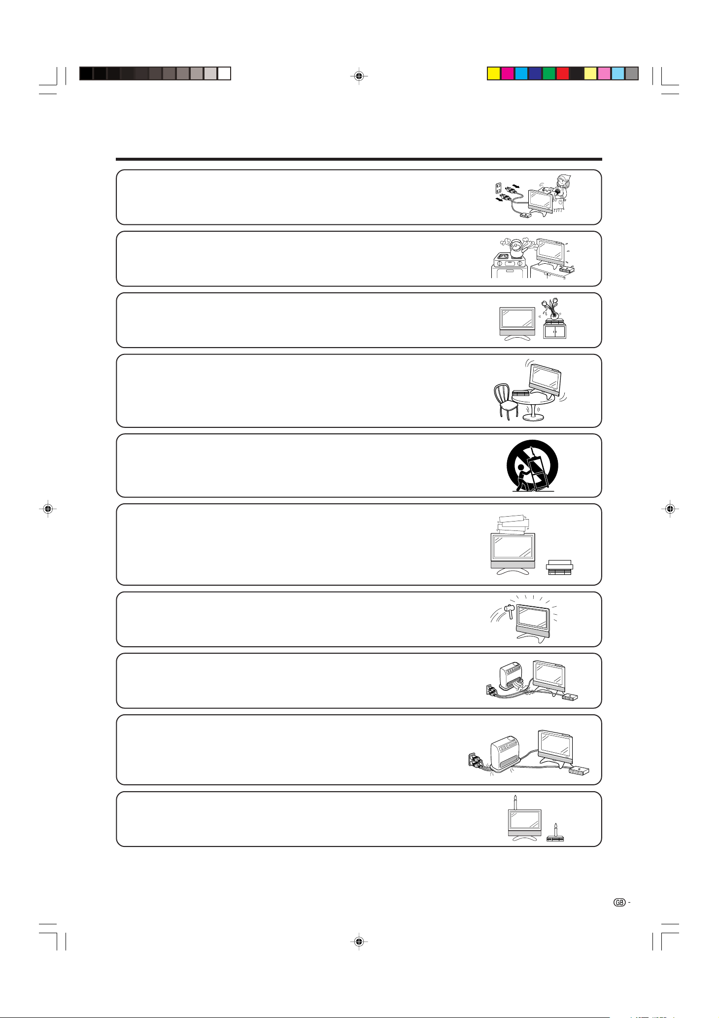
• Cleaning—Unplug the AC cord from the AC outlet before cleaning the product.
Use a damp cloth to clean the product. Do not use liquid cleaners or aerosol
cleaners.
• Water and moisture—Do not use the product near water, such as bathtub,
washbasin, kitchen sink, laundry tub, swimming pool and in a wet basement.
• Stand—Do not place the product on an unstable cart, stand, tripod or table. Doing
so can cause the product to fall, resulting in serious personal injuries as well as
damage to the product. Use only a cart, stand, tripod, bracket or table recommended
by the manufacturer or sold with the product. When mounting the product on a
wall, be sure to follow the manufacturer’s instructions. Use only the mounting
hardware recommended by the manufacturer.
• When relocating the product placed on a cart, it must be moved with utmost care.
Sudden stops, excessive force and uneven floor surface can cause the product to
fall from the cart.
• Ventilation—The vents and other openings in the cabinet are designed for ventilation.
Do not cover or block these vents and openings since insufficient ventilation can
cause overheating and/or shorten the life of the product. Do not place the product
on a bed, sofa, rug or other similar surface, since they can block ventilation openings.
This product is not designed for built-in installation; do not place the product in an
enclosed place such as a bookcase or rack, unless proper ventilation is provided
or the manufacturer’s instructions are followed.
• The LCD panel used in this product is made of glass. Therefore, it can break when
the product is dropped or applied with impact. Be careful not to be injured by
broken glass pieces in case the LCD panel breaks.
• Heat sources—Keep the product away from heat sources such as radiators, heaters,
stoves and other heat-generating products (including amplifiers).
• Do not place vases or any other water-filled containers on this product.
The water may spill onto the product causing fire or electric shock.
• To prevent fire, never place any type of candle or naked flames on the top or near
the TV set.
• To prevent fire or shock hazard, do not place the AC power cord under the TV set
or other heavy items.
LC-37AA1M(E)-a 03.11.6, 9:46 AM3
4
Important Safety Precautions
LC-37AA1M
The LCD panel is a very high technology product with 3,147,264 thin film transistors, giving you fine picture
details.
Occasionally, a few non-active pixels may appear on the screen as a fixed point of blue, green or red.
Please note that this does not affect the performance of your product.
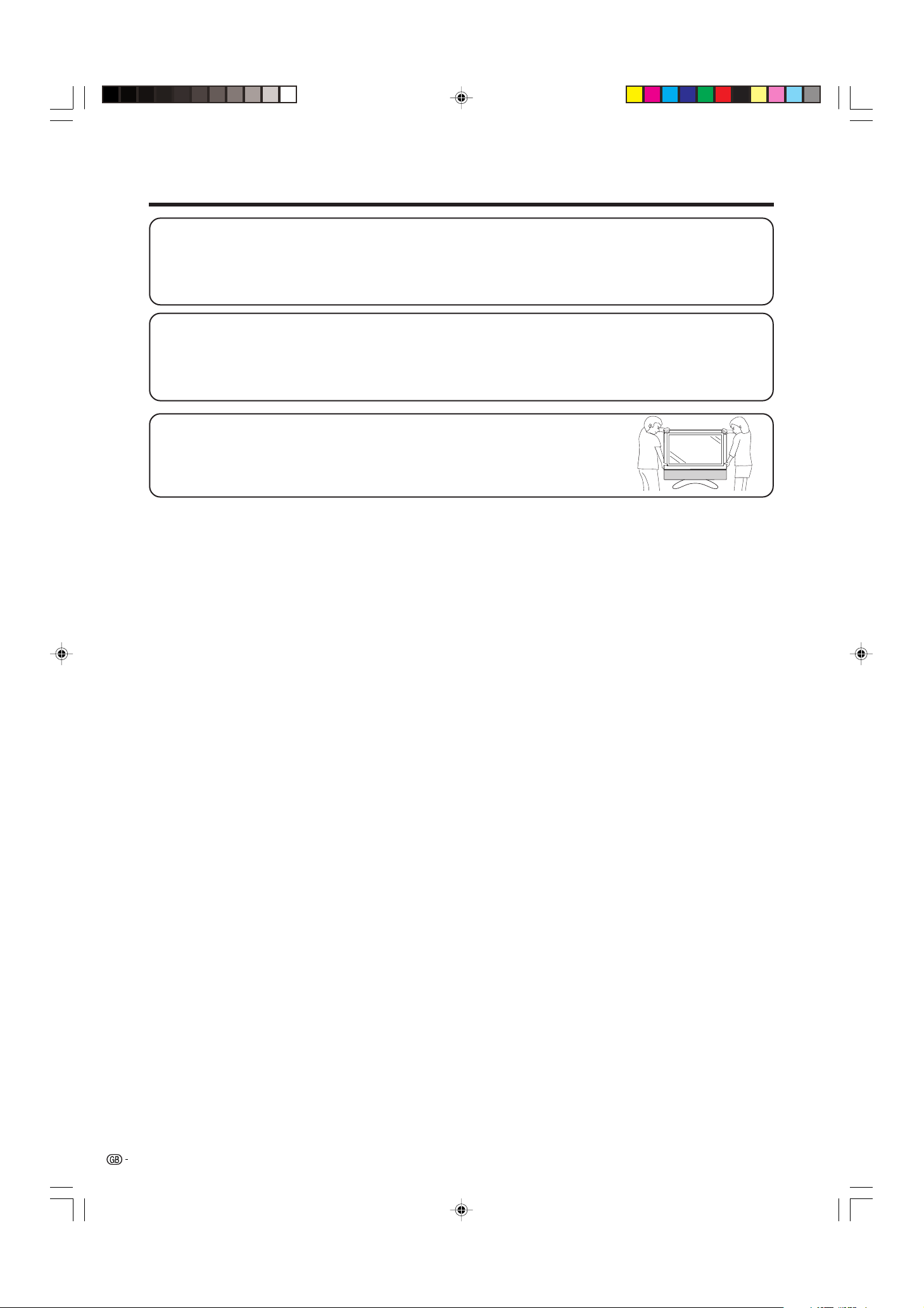
Precautions when transporting the Display
When transporting the Display, never carry it by holding onto the speakers. Be
sure to always carry the Display by two people holding it with two hands—one
hand on each side of the display.
LC-30AA1M
The LCD panel is a very high technology product with 2,949,120 thin film transistors, giving you fine picture
details.
Occasionally, a few non-active pixels may appear on the screen as a fixed point of blue, green or red.
Please note that this does not affect the performance of your product.
LC-37AA1M(E)-a 03.11.6, 9:46 AM4
5
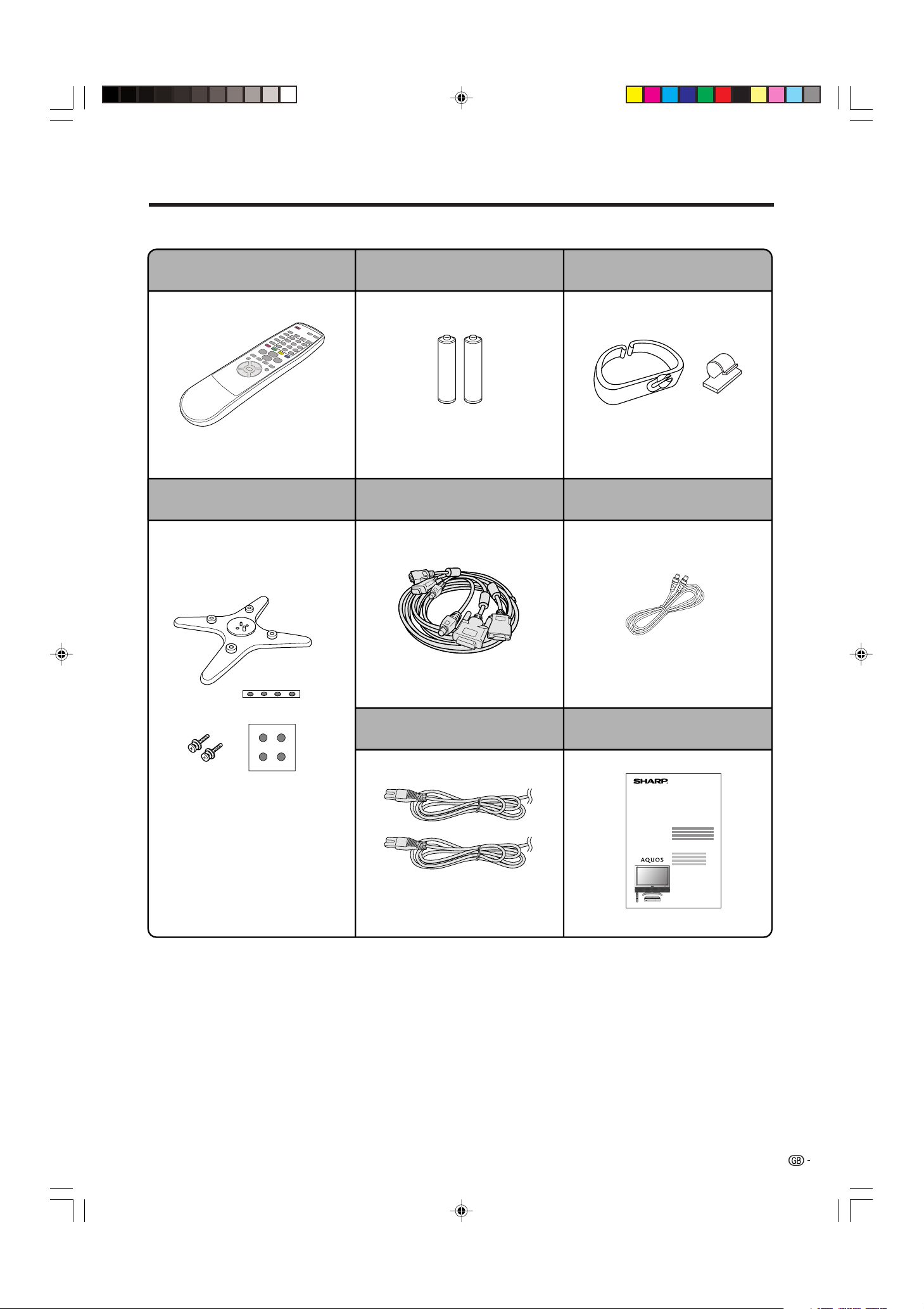
Supplied accessories
Make sure the following accessories are provided with the product.
Remote control unit (g1)
“AA” size battery (g2)
Stand unit (for AVC System) (g1)
System cable (g1)
Cable clamp (Large g1, Small g1)
Page 13 Page 13 Page 8
Page 7
Stand (g1)
Stand cushion (g4)
Stand spacer (g4)
Stand screw (g2)
Page 12
AC cord (g2)
Page 7
Antenna cable (g1)
Page 18
LC-37AA1M
LC-30AA1M
Operation manual
LC-37AA1M(E)-a 03.11.6, 9:46 AM5
6
Preparation
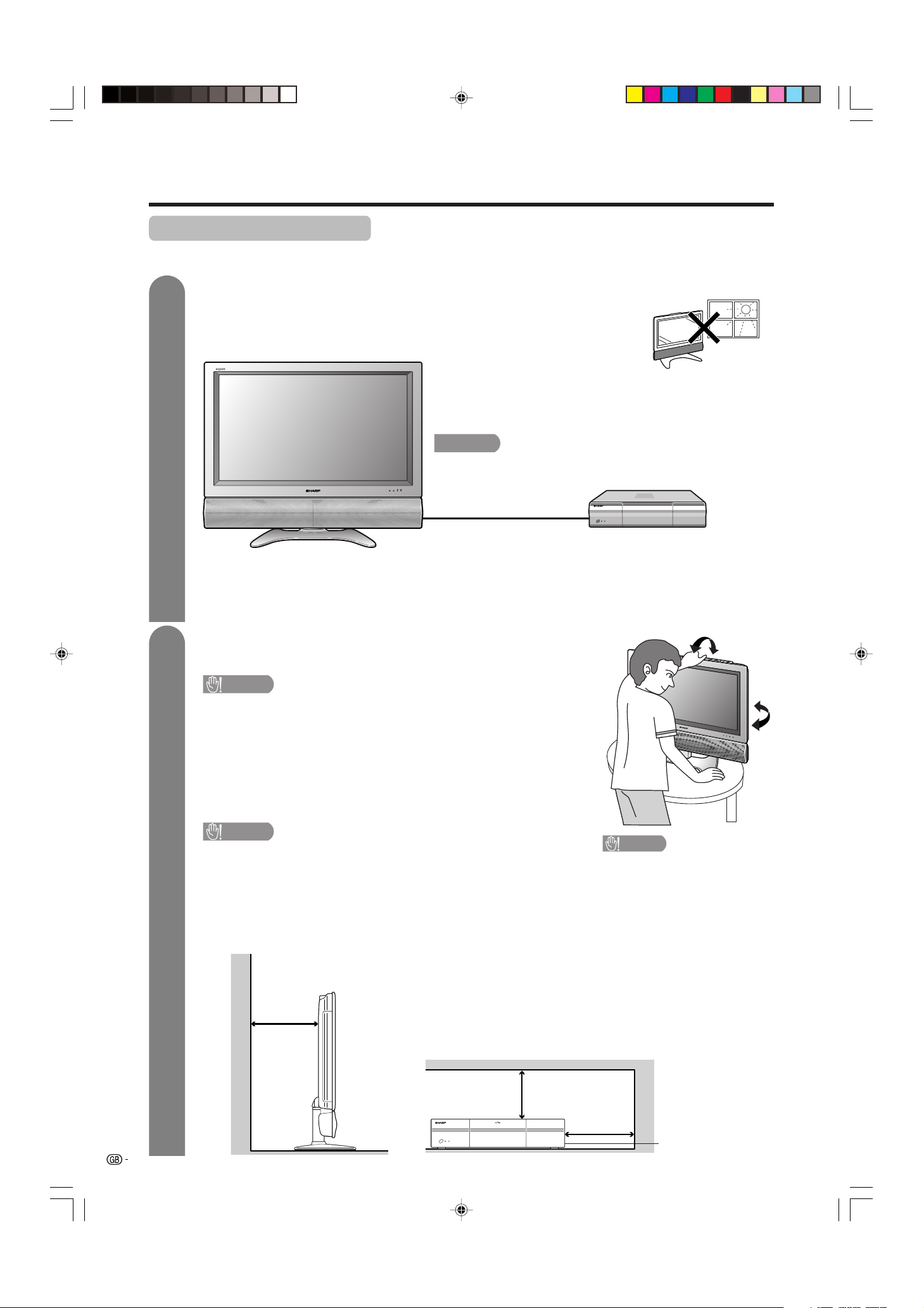
Where to place the System
“System” means the Display and AVC System. First select the location where to place the System.
1
2
Selecting the location of the System
• Select a place with no direct sunlight and good ventilation.
• The Display and the AVC System are connected by the system cable.
(See page 7 for details.)
Setting the System in place
Handling the Display
CAUTION
• The LC-37AA1M Display weighs about 25 kg and the LC-
30AA1M Display weighs about 20 kg. Move it with two or more
people.
• Do not remove the stand from the Display unless using an
optional bracket to mount it.
• Keep enough space above and behind the Display.
Handling the AVC System
CAUTION
• Do not put a VCR or other device on the AVC System.
• Keep enough space above and on the sides of the AVC System.
• Do not block the ventilation openings on the top and left side,
and the exhaust fan on the right side.
• Do not spread a thick cloth beneath the AVC System, or cover it
with one, as this can cause overheating and result in malfunction.
System cable
Display
AVC System
If you want to keep a longer distance between the
Display and AVC System, please purchase the optional
system cable AN-07SC1 (about 7 meters). (See page 76.)
IMPORTANT
• You cannot use external speakers when you are using the optional
system cable (AN-07SC1).
10 cm
or more
5 cm or more
5 cm or more
on both sides
Keep enough space
There is an exhaust fan
on the right side.
CAUTION
Adjust the screen with both
hands. Put one hand on the
Display and tilt the screen
while steadying the stand
with your other hand.
You can adjust the screen
vertically up to 4 degrees
forward or 6 degrees back-
ward, or rotate 10 degrees
horizontally.
LC-37AA1M(E)-a 03.11.6, 9:46 AM6
7
System cable
AVC System (rear view)
AC cord
Display (rear view)
AC cord
System cable
(GREY)
Connect the plug firmly
until the hooks on both
sides click.
(WHITE)
Connect the plug into the
terminal and secure it by
tightening the thumb screws.
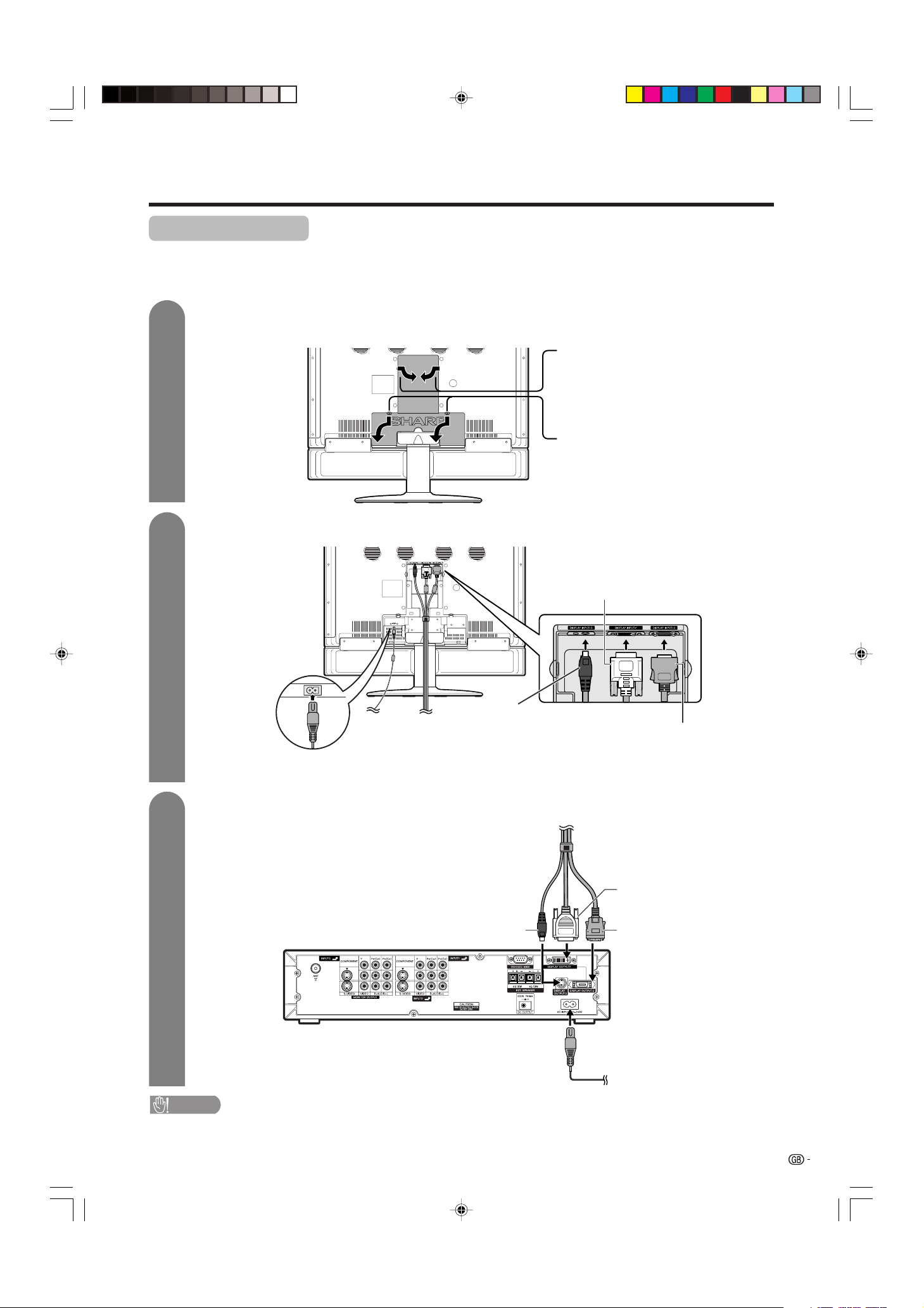
Setting the System
H LC-37AA1M
After putting the Display and the AVC System in place, connect the system cables and AC cords. Use the
cable clamps for bundling the cables.
Preparation
Press down the two
upper hooks to remove
the cover toward you.
Connecting the system cable and the AC cord to the Display
1
2
3
Removing the terminal cover
Connecting the system cable and the AC cord to the AVC System
CAUTION
• TO PREVENT RISK OF ELECTRIC SHOCK, DO NOT TOUCH UN-INSULATED PARTS OF ANY CABLES WITH THE
AC CORD CONNECTED.
Press the two hooks
toward the centre of the
Display and remove the
cover toward you.
(GREY)
(WHITE)
(BLACK)
(BLACK)
LC-37AA1M(E)-a 03.11.6, 9:46 AM7
8
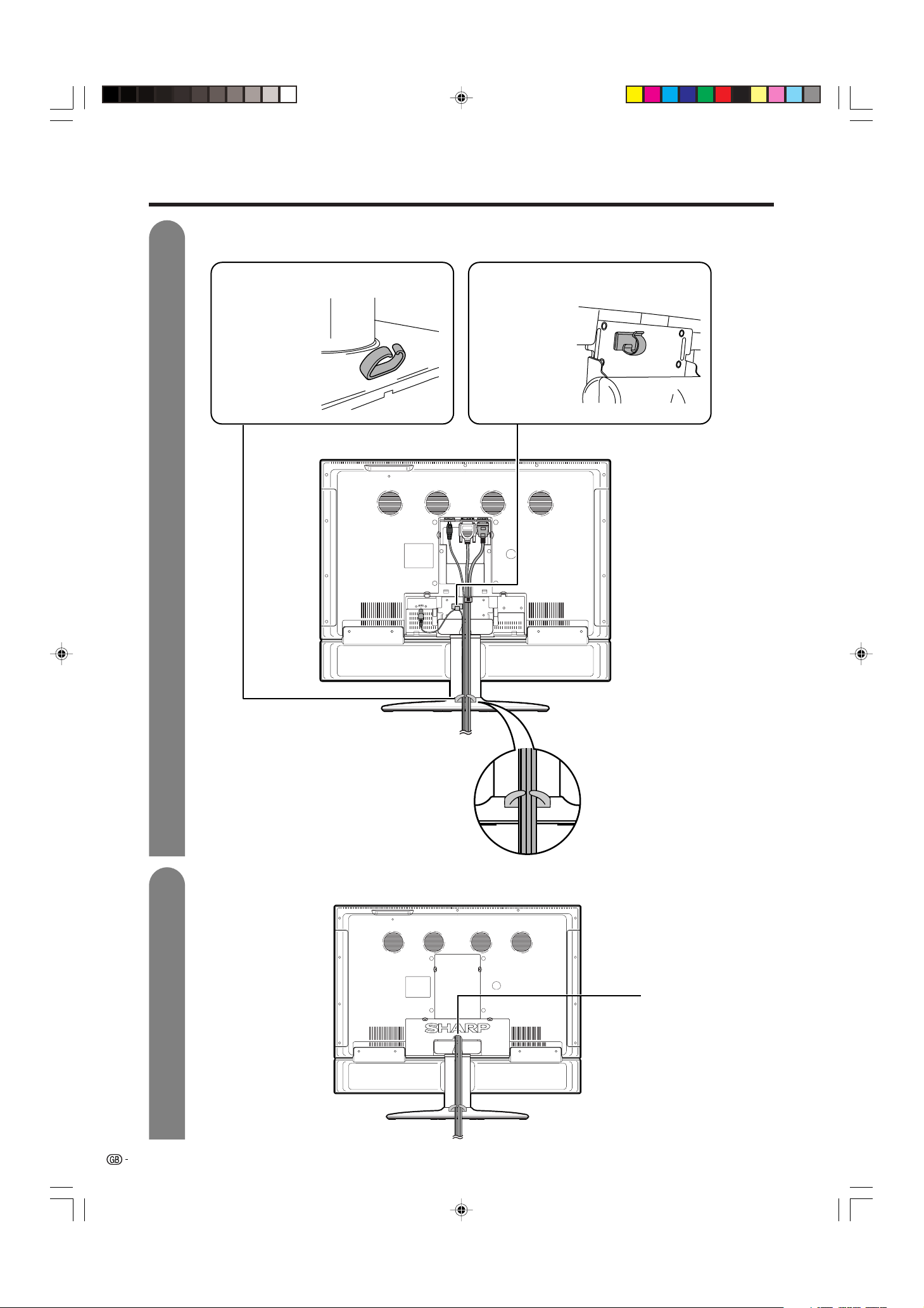
Preparation
4
5
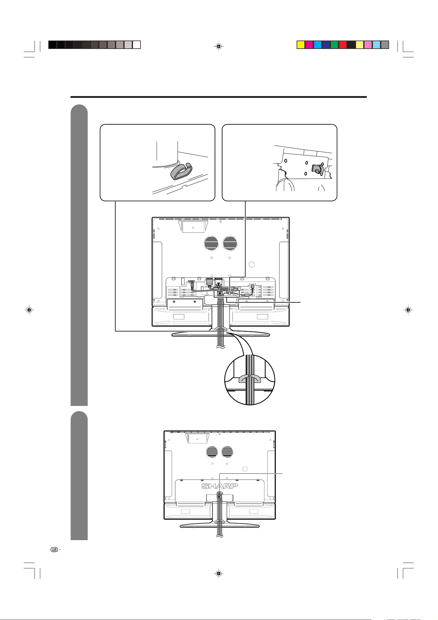
Attaching the clamps and bundling the cables with the clamp
Closing the terminal cover
Cable clamp (Large)
Insert the cable
clamp in the hole
on the Display leg
as shown.
Cable clamp (Small)
Peel off the seal
on the back and
attach as shown.
Display (rear view)
Cables come out
from the small
opening.
LC-37AA1M(E)-a 03.11.6, 9:46 AM8
9
System cable
AVC System (rear view)
AC cord
Display (rear view)
AC cord
System cable
(GREY)
Connect the plug
firmly until the hooks
on both sides click.
(WHITE)
Connect the plug into the
terminal and secure it by
tightening the thumb screws.
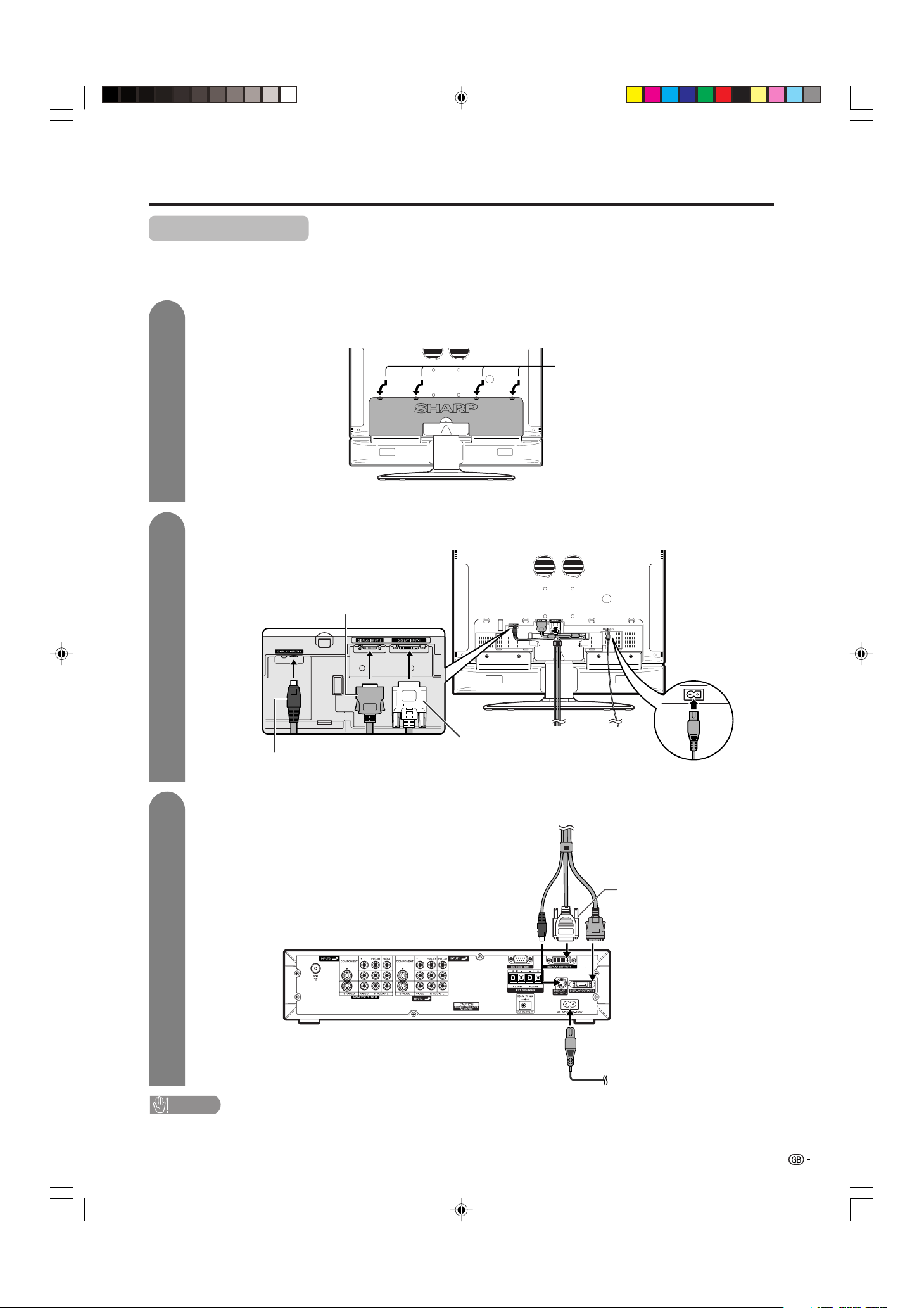
Setting the System
H LC-30AA1M
After putting the Display and the AVC System in place, connect the system cables and AC cords. Use the
cable clamps for bundling the cables.
Preparation
Press down the four
upper hooks to remove
the cover toward you.
Connecting the system cable and the AC cord to the Display
1
2
3
Removing the terminal cover
Connecting the system cable and the AC cord to the AVC System
CAUTION
• TO PREVENT RISK OF ELECTRIC SHOCK, DO NOT TOUCH UN-INSULATED PARTS OF ANY CABLES WITH THE
AC CORD CONNECTED.
(GREY)
(WHITE)
(BLACK)
(BLACK)
LC-37AA1M(E)-a 03.11.6, 9:46 AM9
10
Preparation
4
5
Attaching the clamps and bundling the cables with the clamp
Closing the terminal cover
Cable clamp (Large)
Insert the cable
clamp in the hole
on the Display leg
as shown.
Cable clamp (Small)
Peel off the seal
on the back and
attach as shown.
Display (rear view)
Cables come out
from the small
opening.
Arrange the
system cable as
shown in the
illustration.
LC-37AA1M(E)-a 03.11.6, 9:46 AM10
11
Preparation
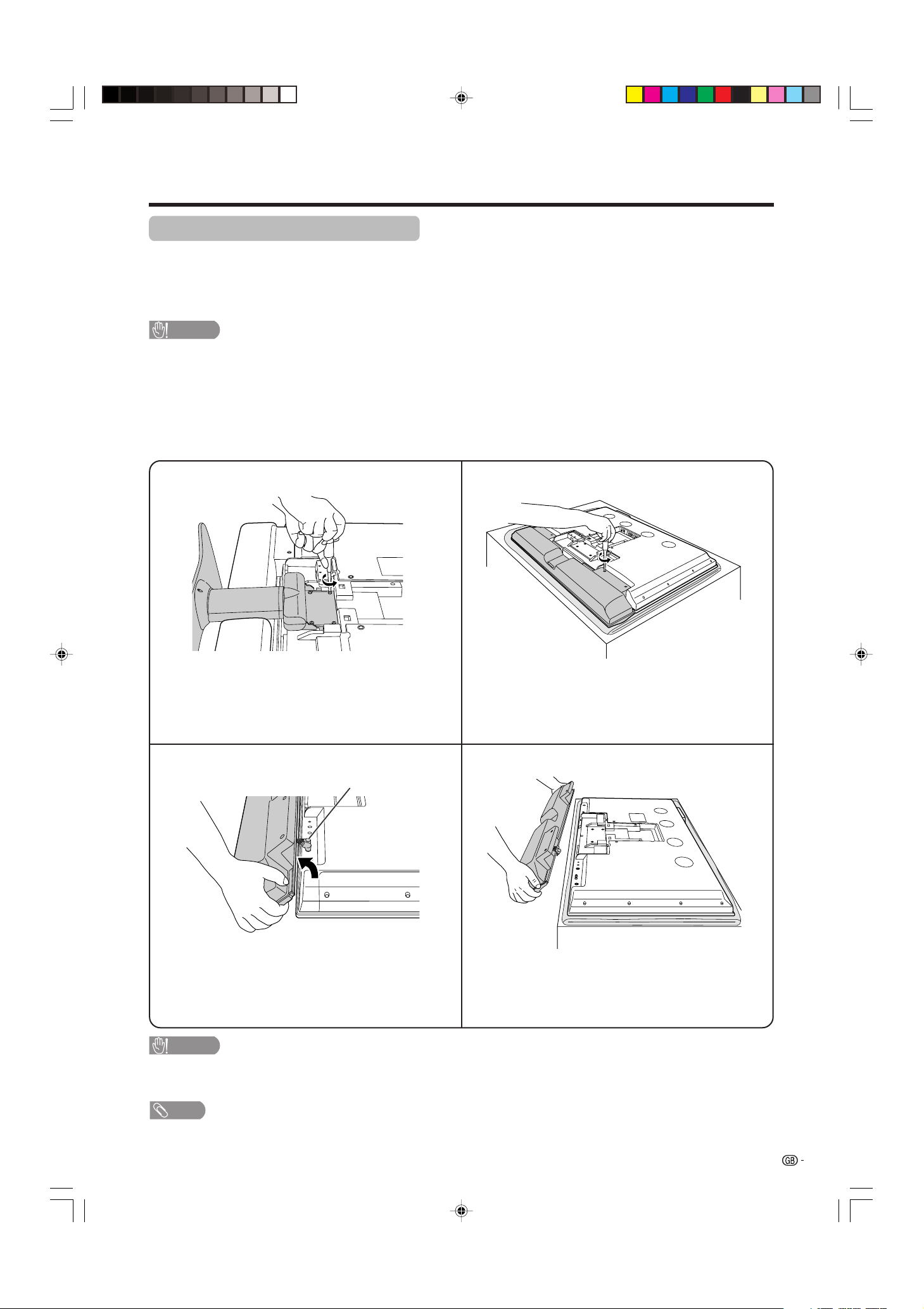
Removing the stand and speaker
This unit has detachable type speaker.
You can detach the system speaker when using external speaker.
Before removing (or attaching) speaker, unplug the AC cord from the AC outlet and the system cable from the
Display.
CAUTION
• When using the TV with the supplied stand attached, do not remove the speaker. Doing so may disturb
the balance leading to product damage or personal injury.
Before attaching/removing speaker
• Before performing work make sure to turn off the System.
• Before performing work spread cushioning over the base area to lay the Display on. This will prevent it from
being damaged.
The graphics in the explanation below use the LC-37AA1M.
CAUTION
• The speaker terminals on the Display are only for the attached speaker. Do not connect any third party plug or speaker
to the terminal.
• Insert the speaker plug completely into the terminal.
NOTE
• To attach the speaker and stand, perform the above steps in reverse order.
2
34
Unfasten the screws used to secure the speaker in
place.
Take hold of the speaker and slowly slide it
sideways.
(The speaker plugs are still inserted, so make
sure not to pull the speaker too far.)
Remove the speaker plugs from the terminal on the
Display.
(Do not remove the plug by pulling the cord.)
Now the speaker can be removing from the Display.
Speaker plug
1
Unfasten the screws used to secure the stand
in place, and then detach the stand from the
Display.
(Hold the stand so it will not drop the stand from
the edge of the base area.)
LC-37AA1M(E)-a 03.11.6, 9:46 AM11
12
Preparation
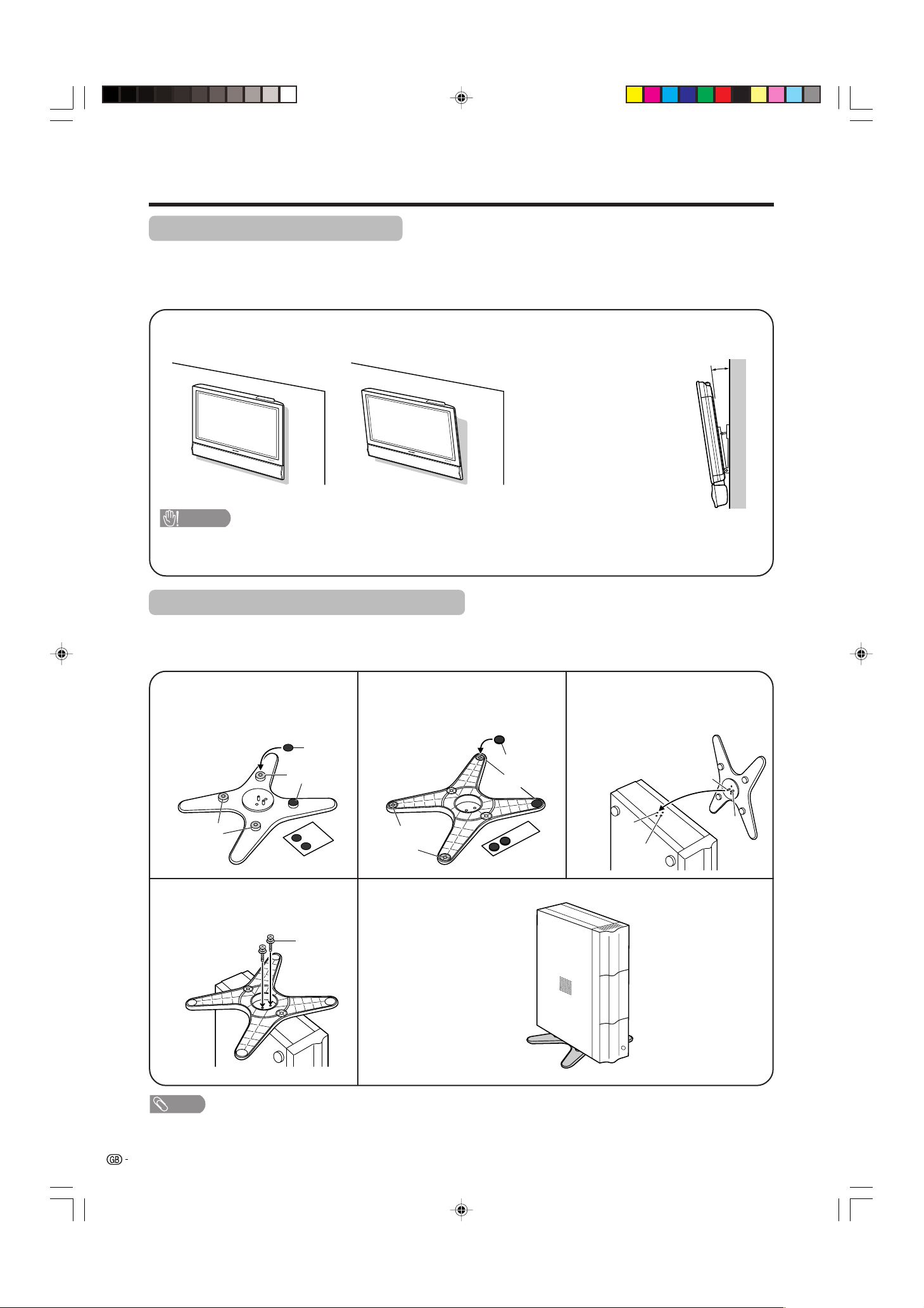
Setting the Display on the wall
Setting the AVC System with the stand
CAUTION
• Installing the LCD Colour TV requires special skill that should only be performed by qualified service personnel.
Customers should not attempt to do the work themselves. SHARP bears no responsibility for improper mounting or
mounting that results in accident or injury.
1
Using an optional bracket to mount the Display
• You can ask a qualified service personnel about using an optional AN-37AG1 bracket to mount the Display
to the wall.
• Carefully read the instructions that come with the bracket before beginning work.
Hanging on the wall
AN-37AG1 wall mount bracket. (See the bracket instructions for details.)
How to install the AVC System vertically using the stand unit.
• Use the supplied stand unit for installing the AVC System vertically in an upright position.
Stick each spacer to the
stand as shown.
Peel each spacer
away from the
paper and attach
to the four bulging
areas on the stand.
2
Attach each cushion to
the stand as shown.
3
Fit the stand to the AVC
System.
Peel each cushion
away from the
paper and attach
to the four areas at
the bottom.
Insert the stand into the AVC
System, making sure that the
thick and thin bulges of the
stand align with the big and
small holes on the AVC
System.
Stand
spacer
Bulge
Stand cushion
Thin bulge
Thick
bulge
Big hole
Small
hole
4
Attach the stand using the
stand screws as shown.
Stand screw
The AVC System installed
vertically with the stand.
NOTE
• When mounting the AVC System vertically, always use the supplied stand. Be careful not to block vent holes when
standing up directly on the floor or a flat surface as this can result in equipment failure.
Bulge
Attaching point
Attaching point
Vertical mounting Angular mounting
About setting the Display angle
• You can set the Display on the
wall up to 5 degrees forward
when the speaker is attached and
up to 20 degrees forward when
the speaker is not attached. Do
not set the angle outside those
ranges.
5°
LC-37AA1M(E)-a 03.11.6, 9:46 AM12
13
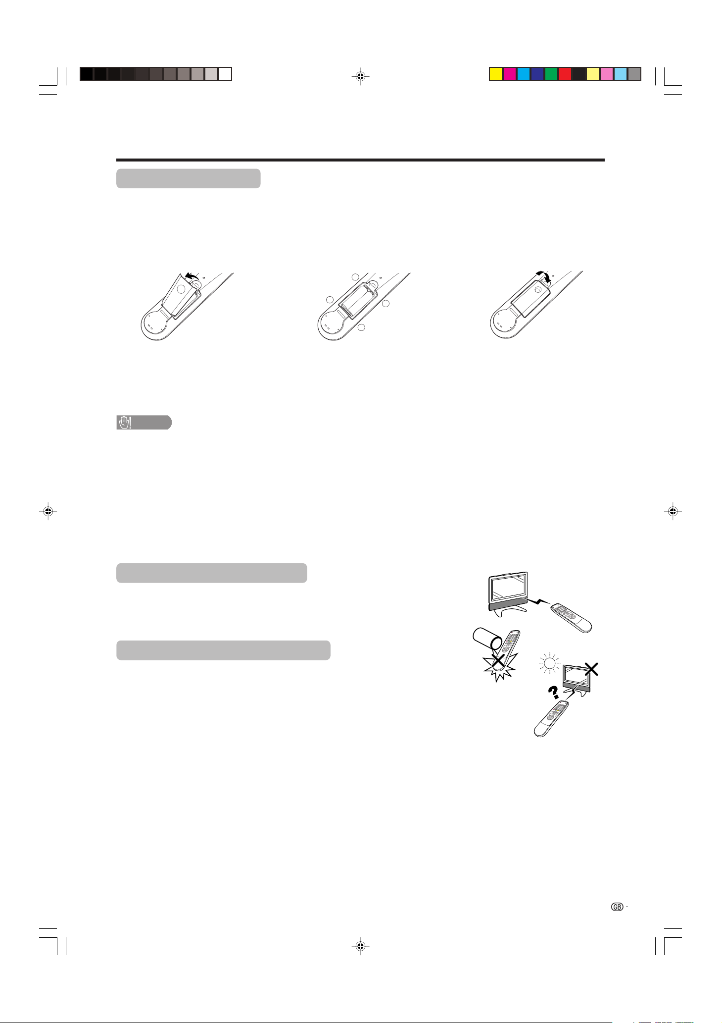
+
+
_
_
1 Open the battery cover. 2 Insert two supplied “AA” size
batteries.
• Place batteries with their terminals
corresponding to the (e) and (f)
indications in the battery compartment.
3 Close the battery cover.
CAUTION
Improper use of batteries can result in chemical leakage or explosion. Be sure to follow the instructions below.
• Place the batteries with their terminals corresponding to the (e) and (f) indications.
• Do not mix batteries of different types. Different types of batteries have different characteristics.
• Do not mix old and new batteries. Mixing old and new batteries can shorten the life of new batteries or cause
chemical leakage in old batteries.
• Remove batteries as soon as they have worn out. Chemicals that leak from batteries can cause a rash. If you
find any chemical leakage, wipe thoroughly with a cloth.
• The batteries supplied with this product may have a shorter life expectancy due to storage conditions.
• If you will not be using the remote control unit for an extended period of time, remove the batteries from it.
Inserting the batteries
Before using the System for the first time, insert two “AA” size batteries (supplied). When the batteries become
depleted and the remote control fails to operate, replace the batteries with new “AA” size batteries.
Using the remote control unit
Use the remote control unit by pointing it towards the remote sensor window.
Objects between the remote control unit and sensor window may prevent proper
operation.
Cautions regarding remote control unit
• Do not expose the remote control unit to shock.
In addition, do not expose the remote control unit to liquids, and do not place
in an area with high humidity.
• Do not install or place the remote control unit under direct sunlight.
The heat may cause deformation of the unit.
• The remote control unit may not work properly if the remote sensor window of
the Display is under direct sunlight or strong lighting. In such case, change
the angle of the lighting or Display, or operate the remote control unit closer to
the remote sensor window.
Preparation
LC-37AA1M(E)-a 03.11.6, 9:47 AM13
14
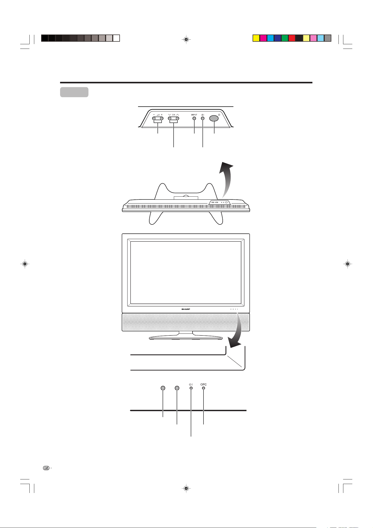
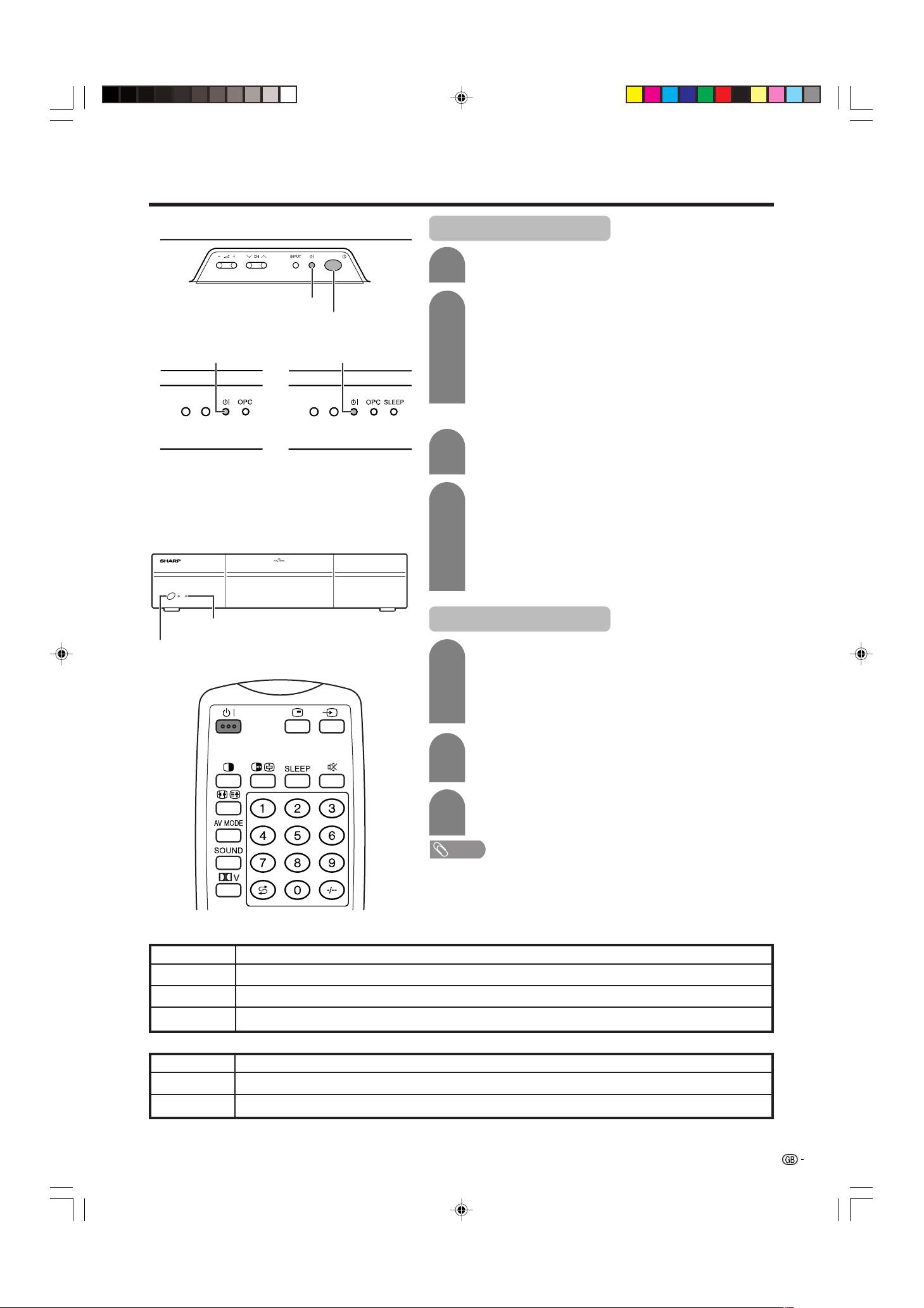
Part names
OPC indicator*
STANDBY/ON indicator
MAIN POWER
button (X)
OPC sensor
Display
H LC-37AA1M
STANDBY/ON button
(B)
INPUT
button
VOLUME buttons
( il/k )
CHANNEL buttons
(CHs/r)
Remote control sensor
*OPC: Optical Picture Control
(See pages 41 and 43.)
LC-37AA1M(E)-a 03.11.6, 9:47 AM14
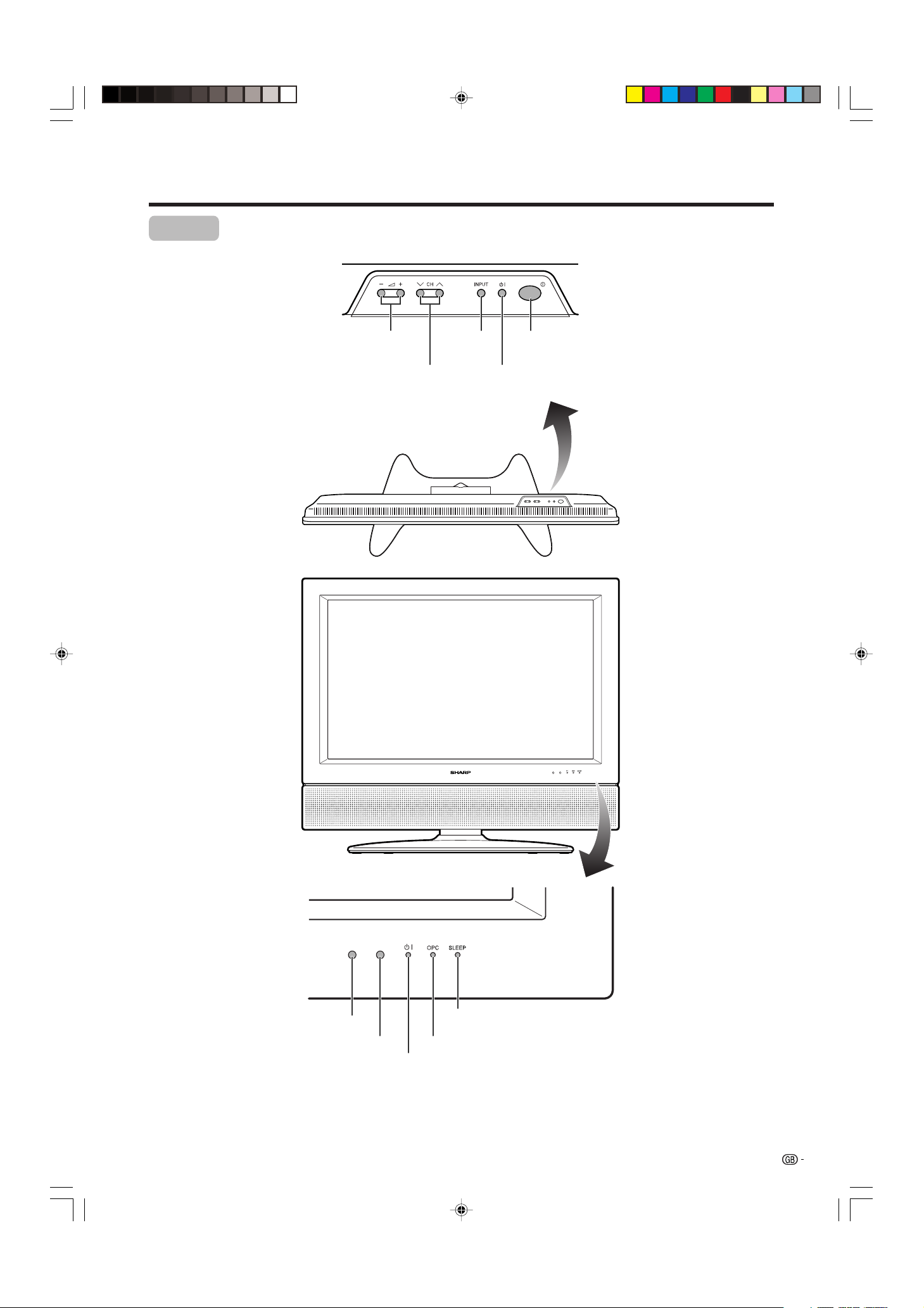
15
OPC indicator*
STANDBY/ON indicator
MAIN POWER
button (X)
OPC sensor
Display
H LC-30AA1M
STANDBY/ON button
(B)
INPUT
button
VOLUME buttons
( il/k )
CHANNEL buttons
(CHs/r)
Remote control sensor
*OPC: Optical Picture Control
(See pages 41 and 43.)
SLEEP timer indicator
Part names
LC-37AA1M(E)-a 03.11.6, 9:47 AM15
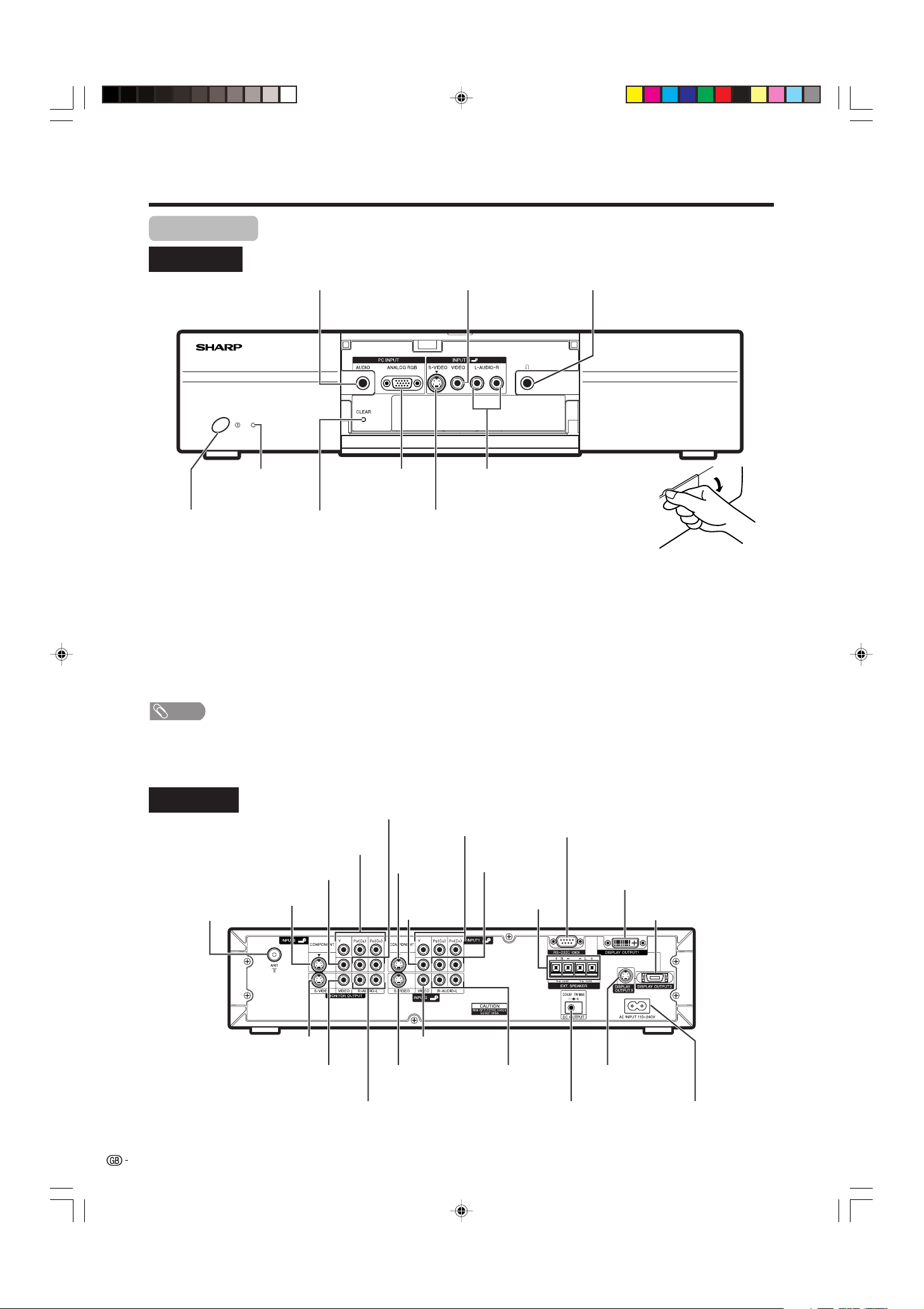
16
CLEAR*
X (POWER) button
INPUT 4 terminal (S-VIDEO)
PC INPUT terminal (AUDIO)
INPUT 4 terminals (AUDIO)
PC INPUT terminal
(ANALOG RGB)
* If the AVC System is switched on but it does not appear to be operating correctly, it may need resetting. In this
case, press CLEAR, shown in the diagram, lightly with the end of a ballpoint pen or other pointed object.
This will reset the System as shown below.
• AV MODE resets to USER.
• TV channel resets to channel 1.
• Dual screen resets to normal.
• Audio setting initialises.
• Dolby Virtual resets to OFF.
• Image position is initialised.
NOTE
• Pressing CLEAR will not work if the System is in standby mode (indicator lights red).
• Pressing CLEAR will not delete channel preset or password. See page 66 for resetting the password when you know it.
See page 80 for initialising to the factory preset values when you forget your password.
Part names
AVC System
STANDBY/ON indicator
INPUT 4 terminal (VIDEO)
(How to open the door)
Front view
Rear view
Headphone
(When connecting headphones,
the sound from the speakers is
muted.)
ANTENNA INPUT
terminal
INPUT 3 terminal
(S-VIDEO)
INPUT 3 terminal
(VIDEO)
INPUT 3 terminals
(Y, P
B, PR)
INPUT 3 terminals
(AUDIO)
INPUT 1
terminal
(S-VIDEO)
INPUT 1
terminal
(VIDEO)
INPUT 1 terminals
(Y, P
B, PR)
INPUT 1 terminals
(AUDIO)
RS-232C terminal
DISPLAY OUTPUT1
terminal
AC INPUT terminal
DISPLAY OUTPUT2
terminal
INPUT 2 terminals
(AUDIO)
INPUT 2 terminal
(VIDEO)
INPUT 2 terminal
(S-VIDEO)
MONITOR OUTPUT terminals (AUDIO)
MONITOR OUTPUT terminal (VIDEO)
MONITOR OUTPUT terminal
(S-VIDEO)
DC OUTPUT terminal
(Terminal for expanded
functionality in the near future.)
DISPLAY OUTPUT3
terminal
EXTERNAL
SPEAKER
terminals
LC-37AA1M(E)-a 03.11.6, 9:47 AM16
17
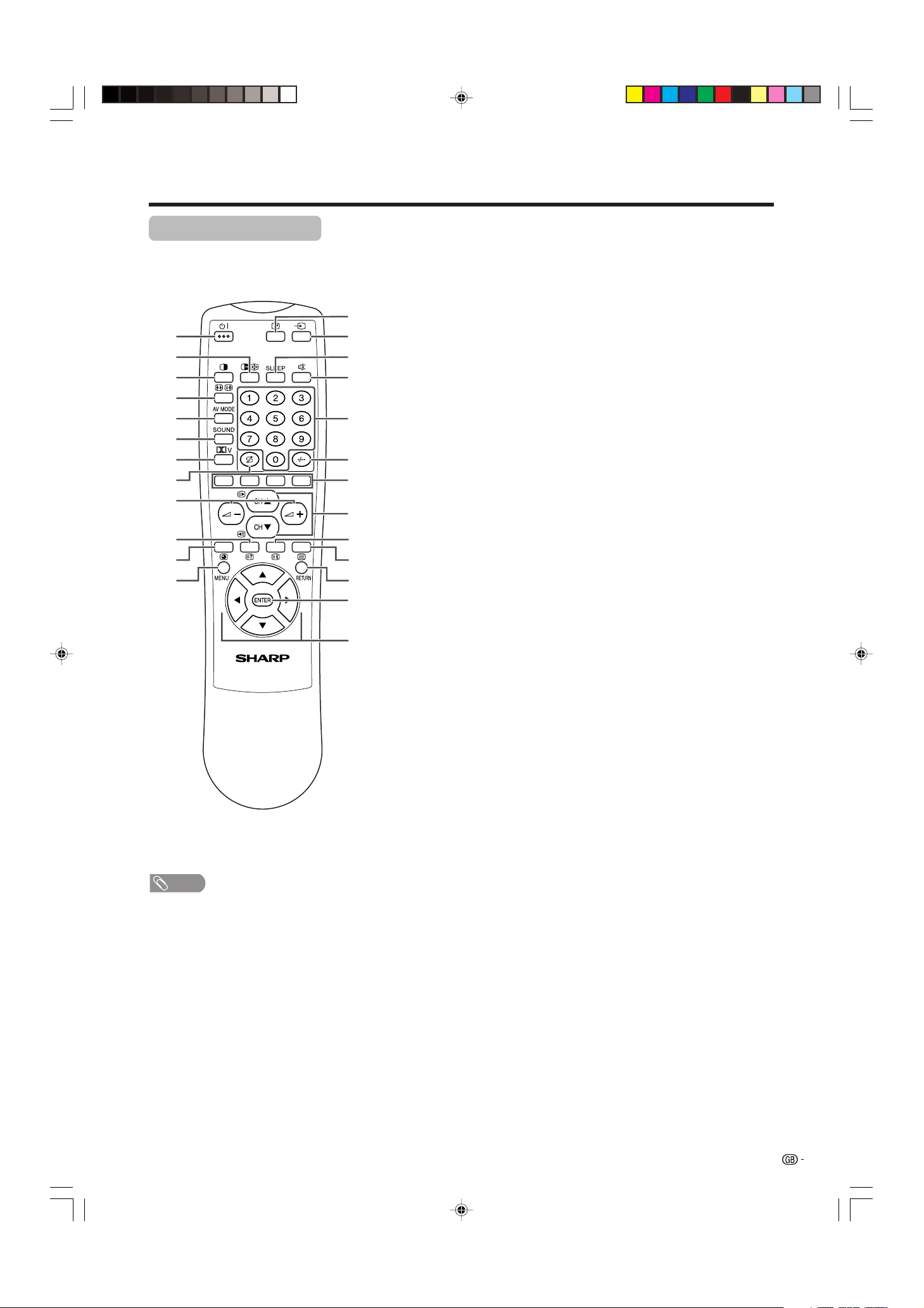
Part names
1 B (STANDBY/ON)
To switch the power on and off. (See page 19.)
2 du (FREEZE/HOLD for TELETEXT)
TV/External input mode: Change the still image mode.
TELETEXT mode: Freeze a multi-page on screen while other
pages are automatically updated. Press d again to return to the
normal image. (See pages 68 and 69.)
3 c (DUAL screen)
Set the dual picture mode. Press c again to return to normal view.
(See page 67.)
4 fv (WIDE MODE/ T/B/F)
TV/External input mode: Change the wide image mode. (See pages
58 and 59.)
TELETEXT mode: Set the area of magnification. (full/upper half/
lower half) (See page 69.)
5 AV MODE
Select a video setting: AV MODE (USER, STANDARD, DYNAMIC,
MOVIE, GAME), PC MODE (USER, STANDARD) (See page 57.)
6 SOUND
Select the sound multiplex mode. (See page 23.)
7 ]*
Select Virtual Dolby Surround settings. (See page 22.)
8 A (Flashback)
Press to return to the previous channel in normal viewing mode.
Press to return to the previous page in TELETEXT mode. (See page
20.)
9 il/ik (VOLUME)
Set the volume. (See page 21.)
10 k (Reveal hidden for TELETEXT)
TELETEXT mode: Display hidden characters. (See page 69.)
11 j (SUBPAGE for TELETEXT)
TELETEXT mode: Change the picture mode for sub-page selecting.
(See page 70.)
12 MENU
Display the MENU screen.
13 C (CHANNEL INFORMATION)
Display the channel information and time. (See page 71 for details
on the time display.)
14 b (INPUT SOURCE)
Select an input source. (TV, INPUT 1, INPUT 2, INPUT 3, INPUT 4,
PC) (See pages 45-49 and 55.)
15 SLEEP
Set the Sleep timer. (See page 64.)
16 e (MUTE)
Mute the sound. (See page 21.)
17 0 – 9
TV/External input mode: Set the channel.
TELETEXT mode: Set the page.
18 o (Digit for channel select)
Change the digits of the selected TV channel. (See page 20.)
19 Colour (RED/GREEN/YELLOW/BLUE)
TELETEXT mode: Select a page. (See page 69.)
20 CHa/CHb(w/x )
TV/External input mode: Select the channel.
TELETEXT mode: Set the page. (See page 69.)
21 l (TOP Overview for TELETEXT)
TELETEXT mode: Display an index page for CEEFAX/FLOF
information. TOP Overview for TOP programme. (See page 70.)
22 m (TELETEXT)
Select the TELETEXT mode. (all TV image, all TEXT image, TV/TEXT
image) (See pages 69 and 70.)
23 RETURN
MENU mode: Return to the previous menu screen.
24 ENTER
Execute a command.
Return to the initial image position after moving with a/b/c/d.
25 a/b/c/d (Cursor)
Select a desired item on the setting screen.
Move the picture on the screen.
1
2
3
4
5
6
7
8
9
10
11
12
14
15
13
16
17
18
19
20
21
22
23
24
25
NOTE
• When using the remote control unit, point it
at the Display.
• Manufactured under license from BBE
Sound, Inc.
Licensed by BBE Sound, Inc. under
USP4638258, 5510752 and 5736897. BBE
and BBE symbol are registered trademarks
of BBE Sound, Inc.
* Manufactured under license from Dolby
Laboratories. “Dolby”, “Pro Logic” and the
double-D symbol are trademarks of Dolby
Laboratories.
Remote control unit
LC-37AA1M(E)-a 03.11.6, 9:47 AM17
18
Watching TV
Standard DIN45325 plug (IEC169-2)
75-ohm coaxial cable (round cable)
Simple operations for watching a TV programme
Basic connection
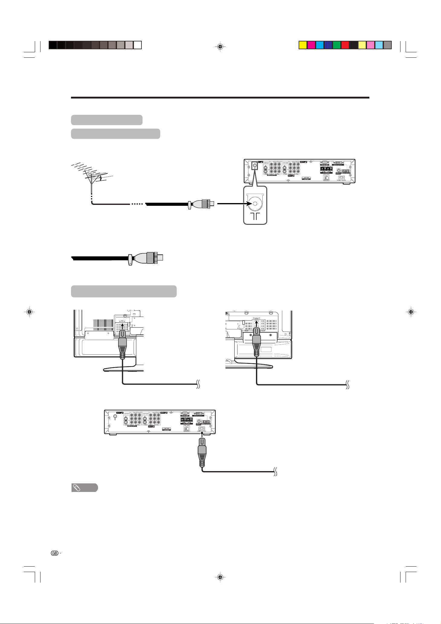
Connecting to an antenna
To enjoy a clearer picture, use an outdoor antenna. The following is a brief explanation of the types of connections
that are used for coaxial cable.
Antenna cable
If your outdoor antenna uses a 75-ohm coaxial cable with a standard DIN45325
plug (IEC 169-2), plug it into the ANTENNA INPUT terminal at the rear of the
AVC System.
Connecting to the power outlet
Display (rear view)
Display (rear view)
Plug in to wall outlet.
Plug in to wall outlet.
Plug in to wall outlet.
AVC System (rear view)
NOTE
• Always turn off the main power of Display and AVC System when connecting the AC cords.
• Disconnect the AC cords from the AC outlet, Display and AVC System if the System will not be used for a long period of
time.
* This picture is for LC-37AA1M. * This picture is for LC-30AA1M.
LC-37AA1M(E)-b 03.11.6, 9:48 AM18
19
Watching TV
Display
AVC System
Off
Flashing red
Red
Green
Display status indicator
Power off
AVC System does not turn on or its AC cord is disconnected.
The System is in standby mode.
The System is on.
Turning on the power
STANDBY/ON indicator
X (POWER)
X (MAIN POWER)
STANDBY/ON indicator
B (STANDBY/ON) button
1
2
3
Press X (MAIN POWER) on the Display.
• The STANDBY/ON indicator on the Display flashes red.
Press X (POWER) on the AVC System.
• The System turns the power on.
• The STANDBY/ON indicator on the Display lights up
green and the one on the AVC System lights up green.
• If the STANDBY/ON indicators still light up red, press
B on the remote control unit or B (STANDBY/ON)
button on the Display to turn the System on.
Turning off the power
Press B on the remote control unit or B
(STANDBY/ON) button on the Display.
• The System enters standby mode and the image on the
screen disappears.
• Both STANDBY/ON indicators change from green to red.
Press X (POWER) on the AVC System.
• The STANDBY/ON indicator on the AVC System turns
off and the one on the Display flashes red.
Press X (MAIN POWER) on the Display.
• The STANDBY/ON indicator on the Display gradually
turns off.
When turning the AVC System on first
Press X (POWER) on the AVC System.
• The STANDBY/ON indicator on the AVC System lights
up red.
Press X (MAIN POWER) on the Display.
• The System turns the power on.
• The STANDBY/ON indicator on the Display lights up
green and the one on the AVC System lights up green.
• If the STANDBY/ON indicators still light up red, press
B on the remote control unit or B (STANDBY/ON)
button on the Display to turn the System on.
1
2
NOTE
• If you are not going to use this System for a long period of time, be
sure to remove the AC cords from the power outlet.
• Weak electric power is still consumed even when both X (MAIN
POWER) and X (POWER) are turned off.
1
2
AVC System status indicator
Power off
Only the AVC System is in standby mode or the System is in standby mode.
The System is on.
Off
Red
Green
LC-37AA1M
LC-30AA1M
LC-37AA1M(E)-b 03.11.6, 9:48 AM19
20
Watching TV
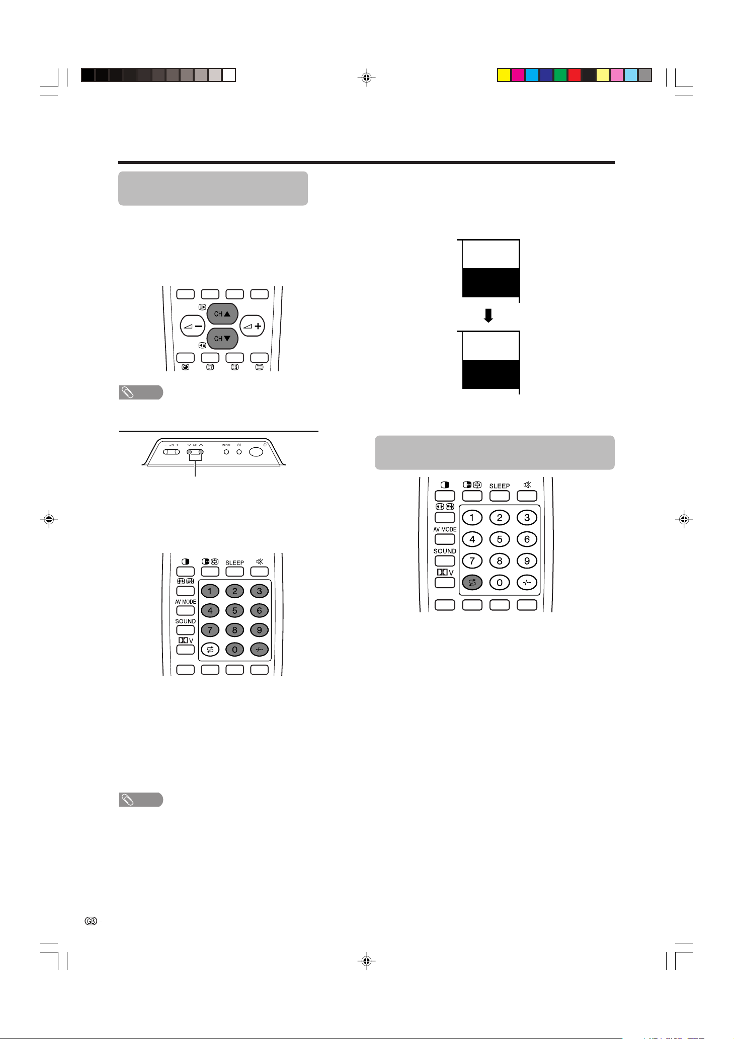
Simple button operations for
changing channels
You can change channels in several ways.
Using CH
aa
aa
a/
bb
bb
bon the remote control unit
• Press CH
aa
aa
a to increase channel number.
• Press CH
b b
b b
b to decrease channel number.
NOTE
• CHs/r on the Display operates the same as CH
bb
bb
b/
aa
aa
a
on the remote control unit.
Channel display
MONO
12
SAT.1
12
SAT.1
B/G
PAL
(Example)
CHs/r
Using 0 – 9 on the remote control unit
Select the channels directly by pressing buttons 0 to
9.
a
To select a 1-digit channel (e.g. channel 2):
• Press 2. If “2” is indicated and the picture does not
change, press o to switch over to the 1-digit select
mode and press 2 again.
To select a 2-digit channel (e.g. channel 12):
• Press o to set the 2-digit select mode. Press 1,
followed by 2.
NOTE
• Complete this procedure within 3 seconds, otherwise the
selection will not be made on the 2-digit channel mode.
Using Flashback (A) on the remote
control unit
Press A to switch the currently tuned channel to the
previously tuned channel.
Press A again to switch back to the currently tuned
channel.
When viewing Teletext information
View a page directly which is 3-digit page number from
100 to 899 by pressing buttons 0 to 9. With Teletext,
you do not use o. (See page 70).
Channel display changes approximately after 3
seconds as shown below.
LC-37AA1M(E)-b 03.11.6, 9:48 AM20
21
Watching TV
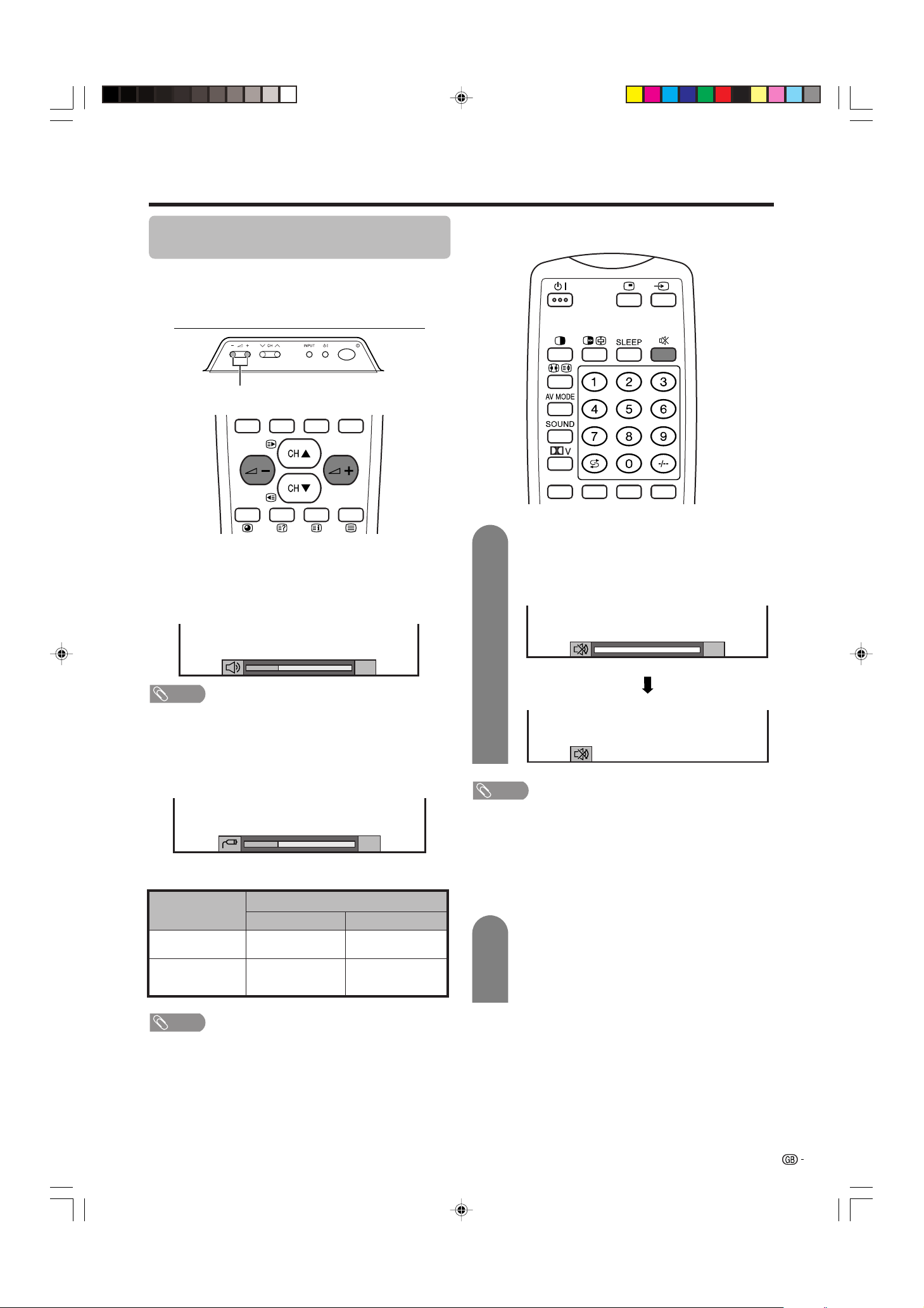
Simple button operation for changing
volume/sound
Changing the volume
You can change the volume on the Display or on the
remote control unit.
NOTE
• “TV”, “INPUT1”, “INPUT2”, “INPUT3”, “INPUT4” and “PC”
modes can each store volume adjustment values
separately.
Audio status
When “Audio Out” is set to “Variable”, the indicator on
the screen changes as shown below.
Output device
Variable sound
Audio out
VariableFixed
Variable sound
Constant as
specified
Mute
20
Speaker
MONITOR
OUTPUT
NOTE
• See page 64 for details on the audio out function.
Using e on the remote control unit
e mutes the current sound output.
Press e.
•“e” has been displayed on the screen for 30
minutes, and the sound is silenced.
Mute
20
0
NOTE
• Within 30 minutes of pressing e, mute can be cancelled
by using one of the two methods below.
• Pressing i
ff
ff
f/i
ee
ee
e, SOUND, CH
aa
aa
a/CH
bb
bb
b, 0 – 9, b or
A can also cancel the mute.
• Changing channels can also cancel the mute.
• Mute will be cancelled after 30 minutes have elapsed.
However, the System will not suddenly output a loud
sound as the volume level is set to 0 automatically.
i
ll
ll
l/
kk
kk
k
• To increase the volume, press i
k k
k k
k.
• To decrease the volume, press i
ll
ll
l.
1
2
Within 30 minutes, Press e again to cancel
the mute.
• Before 30 minutes, the volume level returns to
the previous setting.
• After 30 minutes, increase the volume level by
pressing ie.
LC-37AA1M(E)-b 03.11.6, 9:48 AM21
22
Watching TV
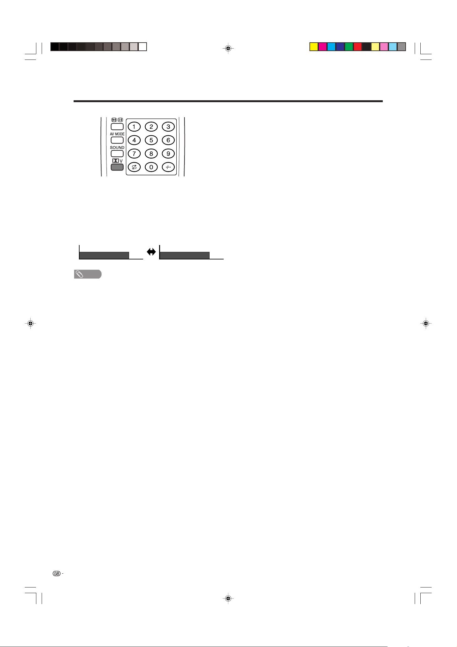
Dolby Virtual : OFF
Dolby Virtual : ON
Using ] on the remote control unit
] produces Dolby virtual effect from the speakers.
Each time you press ], the mode changes
between ON and OFF.
Dolby Virtual sound options
• ON: Makes it possible to enjoy natural, realistic
surround sound.
• OFF: Outputs the normal sound.
NOTE
• You can have the same settings by choosing “Dolby
Virtual” on the menu items. (See page 40.)
LC-37AA1M(E)-b 03.11.6, 9:48 AM22
23
Watching TV
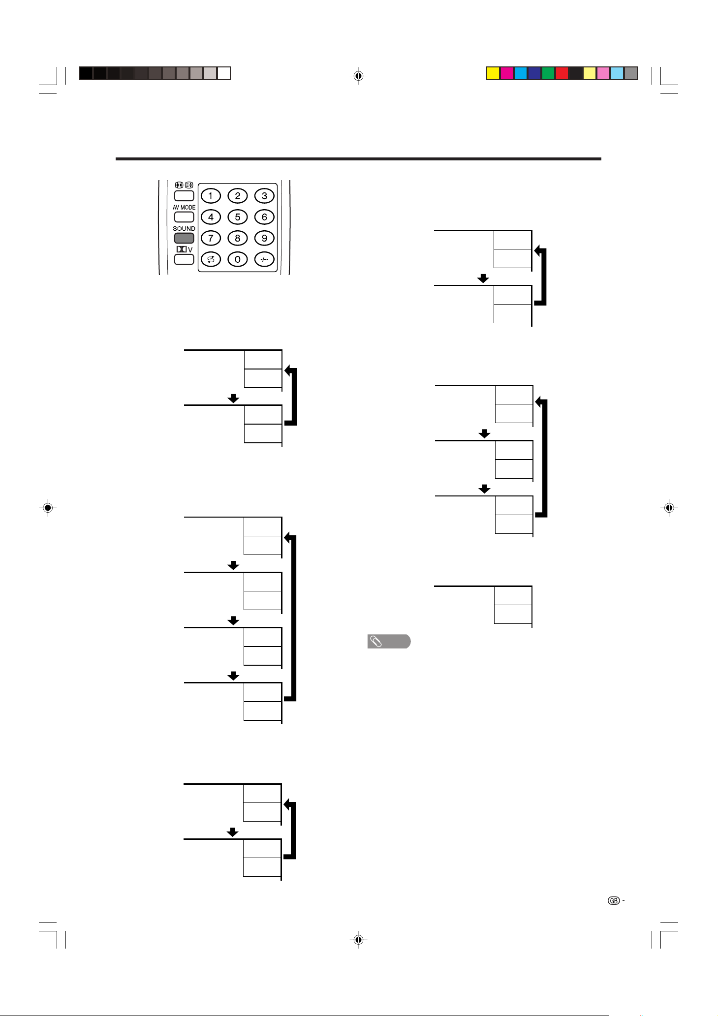
Using SOUND on the remote control unit
In the NICAM TV broadcasts
When receiving a stereo signal
Each time you press SOUND, the mode switches
between NICAM STEREO and MONO.
In the TV mode of A2 TV broadcasts
When receiving a stereo signal
Each time you press SOUND, the mode switches
between STEREO and MONO.
Stereo mode
Bilingual mode
Monaural mode
NICAM
STEREO
99
BBC2
MONO
99
BBC2
NICAM
CH A
99
BBC2
NICAM
CH B
99
BBC2
NICAM
CH AB
99
BBC2
MONO
99
BBC2
NICAM
MONO
99
BBC2
MONO
99
BBC2
Stereo mode
Bilingual mode
Monaural mode
99
BBC2
MONO
99
BBC2
STEREO
CH A
99
BBC2
CH B
99
BBC2
CH AB
99
BBC2
MONO
99
BBC2
When receiving a bilingual signal
Each time you press SOUND, the mode switches
among NICAM CH A, NICAM CH B, NICAM CH AB
and MONO.
When receiving a monaural signal
Each time you press SOUND, the mode switches
between NICAM MONO and MONO.
When receiving a bilingual signal
Each time you press SOUND, the mode switches
among CH A, CH B and CH AB.
When receiving a monaural signal
When you press SOUND, “MONO” displays.
NOTE
• When no signal is input, the sound mode will display
“MONO”.
• “BBC2” and “99” are tentative network name and channel.
LC-37AA1M(E)-b 03.11.6, 9:48 AM23
24
Basic adjustment settings
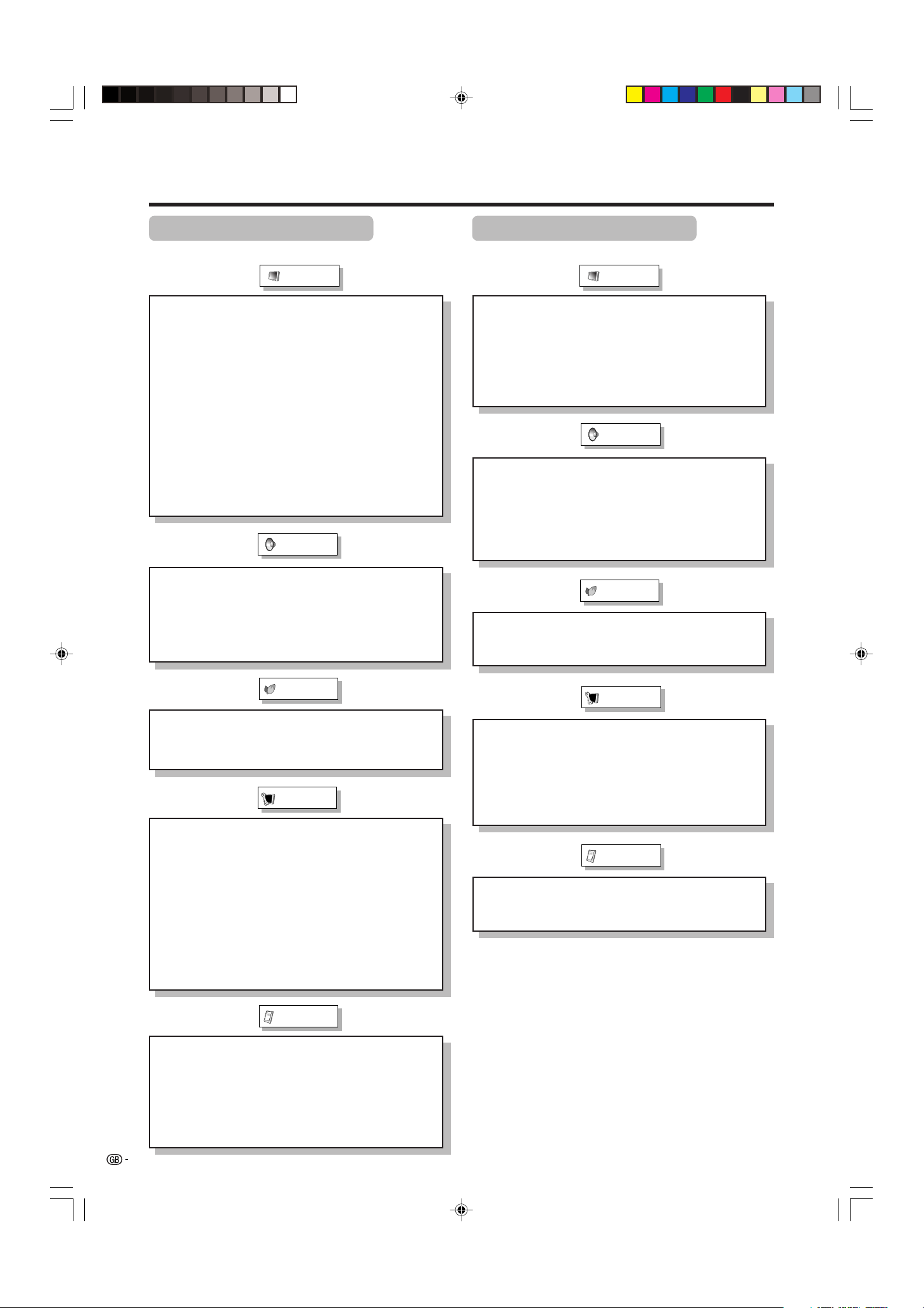
AV input mode menu items
List of AV menu items to help you with operations
Contrast ................................................. Page 35
Brightness ............................................. Page 35
Colour .................................................... Page 35
Tint ......................................................... Page 35
Sharpness ............................................. Page 35
Advanced
C.M.S. .......................................... Page 36
Colour Temp ............................... Page 37
Black ........................................... Page 37
Monochrome .............................. Page 38
Film Mode ................................... Page 38
I/P Setting ................................... Page 39
DNR ............................................. Page 39
Picture
Power Save ............................................ Page 41
No Signal Off ......................................... Page 42
No Operation Off ................................... Page 42
Auto Installation............................ Pages 25-26
Programme Setup ......................... Pages 27-32
Child Lock.............................................. Page 66
Position .................................................. Page 52
WSS ........................................................Page 61
4:3 Mode ................................................ Page 61
Full Mode* .............................................. Page 62
Rotate ..................................................... Page 63
Language ............................................... Page 34
Text Lang. ..............................................Page 68
Treble ..................................................... Page 40
Bass ....................................................... Page 40
Balance .................................................. Page 40
Dolby Virtual .......................................... Page 40
Speaker .................................................. Page 51
Input Select ........................................... Page 55
Input Label ............................................. Page 56
Audio Out............................................... Page 64
Cool Climate .......................................... Page 65
Colour System ...................................... Page 57
Booster .................................................. Page 33
Audio
Power Control
Setup
Option
PC input mode menu items
List of PC menu items to help you with operations
Contrast ................................................. Page 35
Brightness ............................................. Page 35
Red ......................................................... Page 35
Green ...................................................... Page 35
Blue ........................................................ Page 35
C.M.S. ..................................................... Page 36
Picture
Power Save ............................................ Page 43
Power Management .............................. Page 43
Input Signal ........................................... Page 60
Auto Sync. ............................................. Page 54
Fine Sync. .............................................. Page 54
Rotate ..................................................... Page 63
Language ............................................... Page 34
Audio
Power Control
Setup
Option
Treble ..................................................... Page 40
Bass ....................................................... Page 40
Balance .................................................. Page 40
Dolby Virtual .......................................... Page 40
Speaker .................................................. Page 51
Audio Out............................................... Page 64
Cool Climate .......................................... Page 65
* Full Mode is only displayed for LC-30AA1M.
LC-37AA1M(E)-c 03.11.6, 9:50 AM24
 Loading...