


13VT-K150
13VT-K100/150
13VT-CK10
1
SERVICE MANUAL
CONTENTS
Page
» IMPORTANT SERVICE SAFETY PRECAUTION....................................................................................2
» ELECTRICAL SPECIFICATIONS ............................................................................................................ 6
» LOCATION OF USER’S CONTROL........................................................................................................ 7
» DISASSEMBLY AND REASSEMBL Y ......................................................................................................9
» INSTALLATION AND SERVICE INSTRUCTIONS................................................................................. 12
» PRECAUTIONS IN REASSEMBLING ................................................................................................... 17
» FUNCTION OF MAJOR MECHANICAL PARTS....................................................................................18
» ADJUSTMENT, REPLACEMENT AND ASSEMBLY OF MECHANICAL UNITS ...................................20
» ADJUSTMENT OF THE VCR ELECTRICAL CIRCUITR Y.....................................................................40
» TROUBLESHOOTING ........................................................................................................................... 42
» CHASSIS LAYOUT ................................................................................................................................ 55
» BLOCK DIAGRAM OF TV SECTION.....................................................................................................57
» BLOCK DIAGRAM OF VCR SECTION ................................................................................................. 59
» OVERALL SCHEMATIC DIAGRAM.......................................................................................................69
» DESCRIPTION OF SCHEMATIC DIAGRAM......................................................................................... 71
» PRINTED WIRING BOARD ASSEMBLIES ........................................................................................... 83
» REPLACEMENT PARTS LIST............................................................................................................... 89
» PACKING OF THE SET ....................................................................................................................... 108
In the interests of user-safety (Required by safety regulations in some countries ) the set should be restored to its
original condition and only parts identical to those specified should be used.
S48O413VT-K10
MODELS
13VT-K100/150
13VT-CK10
TV/VCR COMBINATION
Chassis No. B97B
SHARP CORPORATION
This document has been published to be used for
after sales service only.
The contents are subject to change without notice.
13VT-K100/150
13VT-CK10
2
IMPORTANT SERVICE SAFETY PRECAUTION
Service work should be performed only by qualified service technicians who are
thoroughly familiar with all safety checks and servicing guidelines which follow:
SERVICING OF HIGH VOLTAGE SYSTEM
AND PICTURE TUBE
When servicing the high voltage system,
remove the static charge by connecting a
10k ohm resistor in series with an insulated
wire (such as a test probe) between the pic-
ture tube ground and the anode lead. (AC
line cord should be disconnected from AC
outlet.)
1. Note that the picture tube in this receiver employs
integral implosion protection.
2. Replace with tube of the same type number for
continued safety.
3. Do not lift picture tube by the neck.
4. Handle the picture tube only when wearing
shatterproof goggles and after discharging the high
voltage anode completely.
CAUTION: FOR CONTINUED
PROTECTION AGAINST A
RISKOF FIRE, REPLACE
ONLY WITH SAME TYPE 4A-
125V FUSE.
4A 125V
WARNING
1. For continued safety, no modification of any circuit
should be attempted.
2. Disconnect AC power before servicing.
3. Semiconductor heat sinks are potential shock
hazards when the chassis is operating.
4. The chassis in this receiver has two ground systems
which are separated by insulation material. The non-
isolated (hot) ground system is for the B+ voltage
regulator circuit and the horizontal output circuit.The
isolated ground system is for the low B+ DC voltages
and the secondary circuit of the high voltage
transformer.
To prevent electrical shock use an isolation
transformer between the line cord and power
receptacle, when servicing this chassis.
X-RADIATION AND HIGH VOLTAGE LIMITS
1. Be sure all service personnel are aware of the
procedures and instructions covering X-radiation.
The only potential source of X-ray in current solid
state TV receivers is the picture tube. However, the
picture tube does not emit measurable X-Ray
radiation if the high voltage is as specified in the "High
Voltage Check" instructions.
It is only when high voltage is excessive that X-
radiation is capable of penetrating the shell of the
picture tube including the lead in glass material. The
important precaution is to keep the high voltage
below the maximum level specified.
2. It is essential that servicepersonel have available at
all times an accurate high voltage meter.
The calibration of this meter should be checked
periodically.
3. High voltage should always be kept at the rated value
-no higher. Operation at higher voltages may cause
a failure of the picture tube or high voltage circuitry
and;also, under certain conditions, may produce
radiation that exceeds specifications.
4. When the high voltage regulator is operating properly
there is no possibility of an X-radiation problem.
Every time a color chassis is serviced, the
brightness should be tested while monitoring the
high voltage with a meter to be certain that the high
voltage does not exceed the specified value and that
it is regulating correctly.
5. Do not use a picture tube other than that specified
or make unrecommended circuit modifications to the
high voltage circuitry.
6. When trouble shooting and taking test
measurements on a receiver with excessive high
voltage, avoid being unnecessarily close to the
receiver.
Do not operate the receiver longer than is necessary
to locate the cause of excessive voltage.
13VT-K100/150
13VT-CK10
3
BEFORE RETURNING THE RECEIVER
(Fire & Shock Hazard)
Before returning the receiver to the user, perform
the following safety checks.
234567890123456789012345678901212345678901234567890123456789012123456789012345678901234567890121
2
SAFETY NOTICE
Many electrical and mechanical parts in television
receivers have special safety-related characteristics.
These characteristics are often not evident from visual
inspection, nor can protection afforded by them be
necessarily increased by using replacement
components rated for higher voltage, wattage, etc.
Replacement parts which have special safety
characteristics are identified in this manual; electrical
components having such features are identified by " å
" and shaded areas in the Replacement Parts Lists and
Schematic Diagrams.
AC
VOLTMETER
1.5k ohm
10W
0.15µF
TEST PROBE
TO EXPOSED
METAL PARTS
CONNECT TO
KNOWN EARTH
GROUND
1. Inspect all lead dress to make certain that leads are
not pinched or that hardware is not lodged between
the chassis and other metal parts in the receiver.
2. Inspect all protective devices such as non-metallic
control knobs, insulating materials, cabinet backs,
adjustment and compartment covers or shields,
isolation resistor-capacity networks, mechanical
insulators, etc.
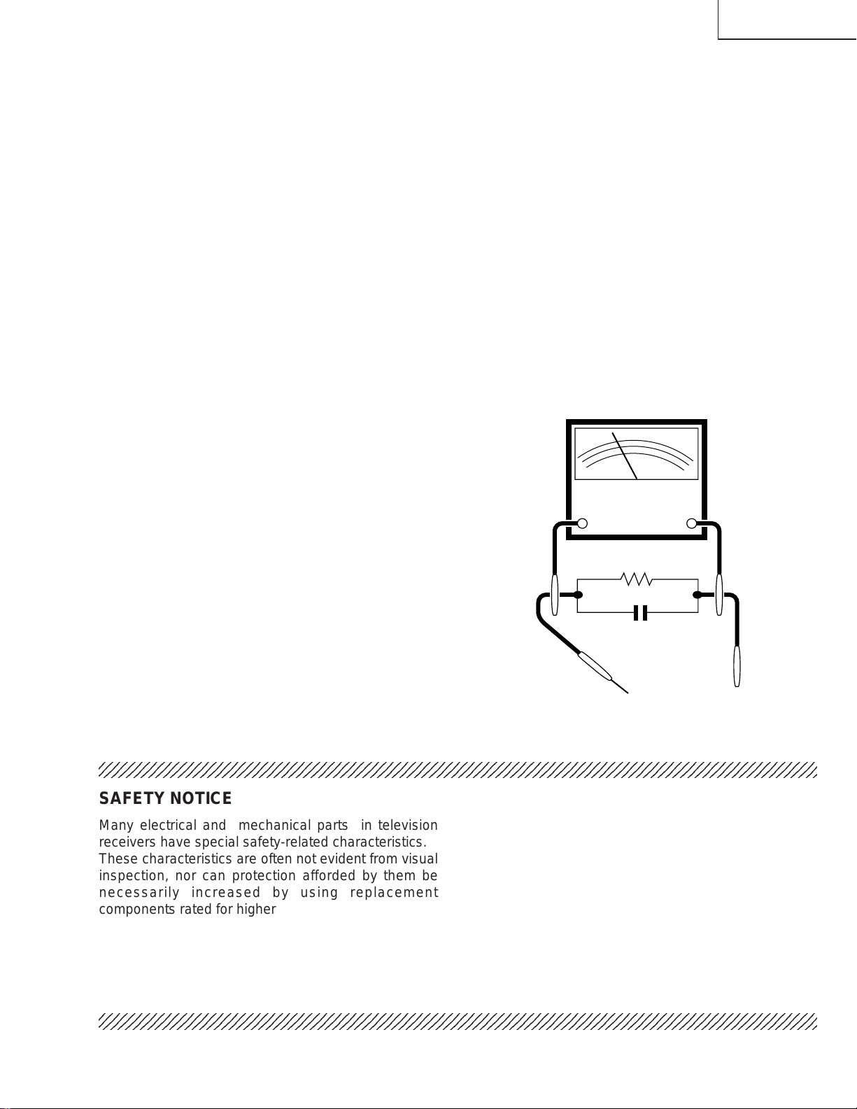
3. To be sure that no shock hazard exists, check for
leakage current in the following manner.
» Plug the AC cord directly into a 120 volt AC outlet,
(Do not use an isolation transformer for this test).
» Using to clip leads, connect a 1.5k ohm, 10 watt
resistor paralleled by a 0.15µF capacitor in series
with all exposed metal cabinet parts and a known
earth ground, such as electrical conduit or electrical
ground connected to earth ground.
» Use an AC voltmeter having with 5000 ohm per volt,
or higher, sensitivity to measure the AC voltage drop
across the resistor.
For continued protection, replacement parts must be
identical to those used in the original circuit. The use of
a substitute replacement parts which do not have the
same safety characteristics as the factory recommended
replacement parts shown in this service manual, may
create shock, fire, X-radiation or other hazards.
» Connect the resistor connection to all exposed metal
parts having a return to the chassis (antenna, metal
cabinet, screw heads, knobs and control shafts,
escutcheon, etc.) and measure the AC voltage drop
across the resistor.
AII check must be repeated with the AC line cord
plug connection reversed. (If necessary, a non-
polarized adapter plug must be used only for the
purpose of completing these check.)
Any current measured must not exceed 0.5 milliamp.
Any measurements not within the limits outlined
above are indicative of a potential shock hazard and
corrective action must be taken before returning the
instrument to the customer.
IMPORTANT SERVICE SAFETY PRECAUTION
(Continued)
234567890123456789012345678901212345678901234567890123456789012123456789012345678901234567890121
2
13VT-K100/150
13VT-CK10
4
PRECAUTIONS A PRENDRE LORS DE LA REPARATION
Ne peut effectuer la réparation qu' un technicien spécialisé qui s'est parfaitement
accoutumé à toute vérification de sécurité et aux conseils suivants.
LIMITES DES RADIATIONS X ET DE LA
HAUTE TENSION
1. Tout le personnel réparateur doit être instruit des
instructions et procédés relatifs aux radiations X.
Le tube-image, seule source de rayons X dons les
téleviseurs transistorisés, n'émet pourtant pas de
rayons mesurables si la haute tension est maintenue
à un niveau préconisé dans la section "Vérification
de la haute tension".
C'est seulement quand la haute tension est
excessive que les rayons X peuvent entrer dans
l'enveloppe du tube-image y compris le conducteur
de verre. Il est important de maintenir la haute tension
en-dessous du niveau spécifié.
2. Il est essentiel que le réparateur ait sous la main un
voltmètre à haute tension qui doit être
périodiquement étalonné.
3. La haute tension doit toujours être maintenue à la
valeur de régime-et pas plus haute. L'opération à
des tensions plus élevées peut entraîner une panne
du tube-image ou du circuit à haute tension et, dans
certaines conditions, peut entraîner une radiation
dépassant les niveaux préscrits.
4. Quand le régulateur à haute tension fonctionne
correctement, il n'y a aucun problème de radiation
X. Chaque fois qu'un châssis couleurs est réparé, la
luminosité doit être examinée bout en contrôlant la
haute tension à l'aide d'un voltmètre pour s'assurer
que la haute tension ne dépasse pas la valeur
spécifiée et qu'elle soit correctement réglée.
5. Ne pas utiliser un tube-image autre que celui spécifié
et ne pas effectuer de modifications déconseillées
du circuit à haute tension.
6. Lors de la recherche des pannes et des mesures
d'essai sur un récepteur qui présente une haute
tension excessive, éviter de s'approcher inutilement
du récepteur.
Ne pas faire fonctionner le récepteur plus longtemps
que nécessaire pour localiser la cause de la tension
excessive.
A VERTISSEMENT
1. N'entreprendre aucune modification de tout circuit.
C'est dangereux.
2. Débrancher le récepteur avant toute réparation.
3. Les déversoirs thermiques à semi-conducteurs
peuvent présenter un danger de choc électrique
lorsque le réceqteur est en marche.
4. Le châssis de ce récepteur a deux systèmes de mise
à la terre qui sont séparés par un matériau isolant.
Le système de mise à la terre non-isolée (chaud)
est pour le circuit du régulateur de tension B+ et le
circuit de sortie horizontale. Le système de mise à
la terre isolé est pour les basses tensions C. C. B+
et le circuit secondaire du transformateur de haute
PRECAUTION:POUR LA
PROTECTION CONTINUE
CONTRE LES RISQUES
D'INCENDIE, REMPLACER LE
FUSIBLE P AR UN FUSIBLE DE
MEME TYPE 4A-125V.
4A 125V
tension.
REP ARA TION DU SYSTEME A HAUTE TEN-
SION ET DU TUBE-IMAGE
Lors de la réparation de ce systéme,
supprimer la charge statique en branchant
une résistance de 10 k en série avec un fil
isolé (comme une sonde d'essai) entre la
mise à la terre du tube-image et le fil
d'anodel. (Le corden d'alimentation doit être
retiré de la prise murale.)
1. Il est à noter que le tube-image de ce récepteur est
intégralement protégé contre l'implosion.
2. Par mesure de sécurité, changer le tube-image pour
un tube du même numéro de type.
3. Ne pas lever le tube-image par son col.
4. Ne manipuler le tube-image qu'en porant des
lunettes incassables et qu'après avoir déchargé
totalement la haute tension.
13VT-K100/150
13VT-CK10
5
VERIFICATIONS CONTRE L'INCEN-DIE ET
LE CHOC ELECTRIQUE
Avant de rendre le récepteur à l'utilisateur , effectuer
les vérifications suivantes.
» T oucher avec la sonde d'essai les pièces métalliques
exposées qui présentent une voie de retour au
châssis (antenne, coffret métallique, tête des vis,
arbres de commande et des boutons, écusson, etc.)
et mesurer la chute de tension CA en-travers de la
résistance.
Toutes les vérifications doivent être refaites après
avoir inversé la fiche du cordon d'alimentation. (Si
nécessaire, une prise d'adpatation non polarisée
peut être utilisée dans le but de terminer ces
vérifications.)
T ous les courants mesurés ne doivent pas dépasser
0,5 mA.
Dans le cas contraire, il y a une possibilité de choc
électrique qui doit être supprimée avant de rendre
le récepteur au client.
234567890123456789012345678901212345678901234567890123456789012123456789012345678901234567890121
2
234567890123456789012345678901212345678901234567890123456789012123456789012345678901234567890121
2
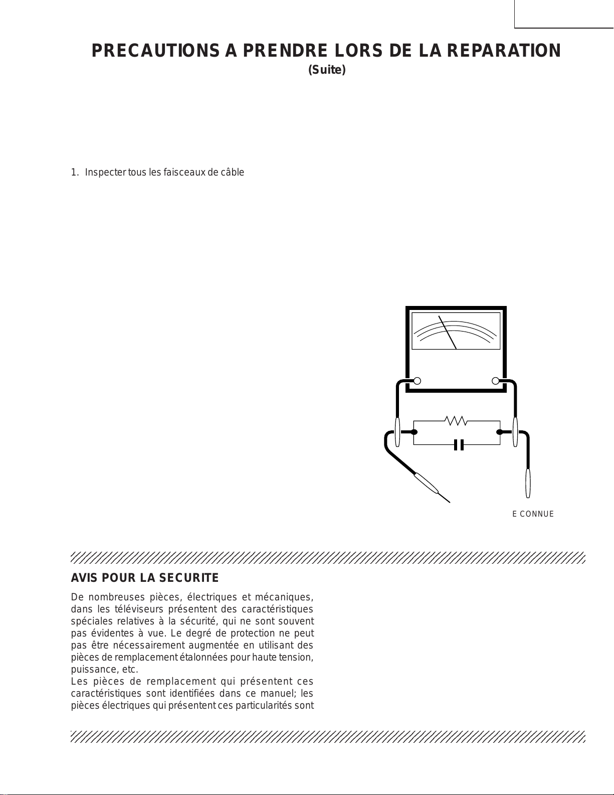
AVIS POUR LA SECURITE
De nombreuses pièces, électriques et mécaniques,
dans les téléviseurs présentent des caractéristiques
spéciales relatives à la sécurité, qui ne sont souvent
pas évidentes à vue. Le degré de protection ne peut
pas être nécessairement augmentée en utilisant des
pièces de remplacement étalonnées pour haute tension,
puissance, etc.
Les pièces de remplacement qui présentent ces
caractéristiques sont identifiées dans ce manuel; les
pièces électriques qui présentent ces particularités sont
PRECAUTIONS A PRENDRE LORS DE LA REPARATION
(Suite)
1. Inspecter tous les faisceaux de câbles pour s'assurer
que les fils ne soient pas pincés ou qu'un outil ne
soit pas placé entre le châssis et les autres pièces
métalliques du récepteur.
2. Inspecter tous les dispositifs de protection comme
les boutons de commande non-métalliques, les
isolants, le dos du coffret, les couvercles ou
blindages de réglage et de compartiment, les
réseaux de résistance-capacité, les isolateurs
mécaniques, etc.
3. S'assurer qu'il n'y ait pas de danger d'électrocution
en vérifiant la fuite de courant, de la facon suivante:
» Brancher le cordon d'alimentation directem-ent à une
prise de courant de 120V. (Ne pas utiliser de
transformateur d'isolation pour cet essai).
» A l'aide de deux fils à pinces, brancher une résistance
de 1,5 k 10 watts en parallèle avec un condensateur
de 0,15µF en série avec toutes les pièces métalliques
exposées du coffret et une terre connue comme une
conduite électrique ou une prise de terre branchée
à la terre.
» Utiliser un voltmètre CA d'une sensibilité d'au moins
5000 /V pour mesurer la chute de tension en travers
de la résistance.
AC
VOLTMETER
1.5k ohm
10W
0.15µF
TEST PROBE
TO EXPOSED
METAL PARTS
CONNECT TO
KNOWN EARTH
GROUND
SONDE D'ESSAI
AUX PIECES
METALLIQUES
EXPOSEES
Voltmètre CA
identifiées par la marque " å " et hachurées dans la
liste des pièces de remplacement et les diagrammes
schématiques.
Pour assurer la protection, ces pièces doivent être
identiques à celles utilisées dans le circuit d'origine.
L'utilisation de pièces qui n'ont pas les mêmes
caractéristiques que les pièces recommandées par
l'usine, indiquées dans ce manuel, peut provoquer des
électrocutions, incendies, radiations X ou autres
accidents.
BRANCHER A UNE
TERRE CONNUE

13VT-K100/150
13VT-CK10
6
ELECTRICAL SPECIFICATIONS
TV SECTION
POWER INPUT: 120 V AC 60 Hz
POWER RATING: 65 W
PICTURE SIZE
Width: 37.8 cm
Height: 38.7 cm
Depth: 38.2 cm
CONVERGENCE: Magnetic
SWEEP DEFLECTION: Magnetic
FOCUS: Hi-Bi-Potential Electrostatic
INTERMEDIATE FREQUENCIES
Picture IF Carrier Frequency: 45.75 MHz
Sound IF Carrier Frequency: 41.25 MHz
Color Sub-Carrier Frequency: 42.17 MHz (Nominal)
AUDIO POWER OUTPUT RATING: 0.8 W (at 10% Distortion)
SPEAKER
Size: 5 × 9 cm (2" × 3
1
/
2
")
Voice Coil Impedance: 16 ohm at 400 Hz
VHF/UHF ANTENNA INPUT IMPEDANCE: 75 ohm unbalanced
TUNING RANGES
VHF-Channels: 2 thru 13
UHF -Channels: 14 thru 69
CATV Channels: 1,14 thru 125 (EIA, Channel Plan)
VCR SECTION
Format: VHS Standard
Video Recording System: Rotary Two-Head Helical Scanning
Number of Video Heads: 2 pcs.
Video Signal Standard: NTSC Color System
Tape Width: 12.7mm (1/2inch)
Tape Speed: (SP)33.35mm/sec (1.31 i.p.s)
(LP)16.67mm/sec (0.66 i.p.s)
Play back only
(EP)11.12 mm/sec (0.44 i.p.s)
Maximum Recording Time: (SP)160 min (T-160)
(EP)480 min (T-160)
Video Input: 0.5 to 2.0 Vp-p, 75 ohm unbalanced
Audio Input: -8 dB, 47k ohm unbalanced (0 dB-0.775 Vrms)
Operating Temperature: 5°C to 40°C (41°F to 104°F)
Storage Temperature: -20°C to 60°C (-4°F to 140°F)
Specifications are subject to change without prior notice.
13VT-K100/150
13VT-CK10
7
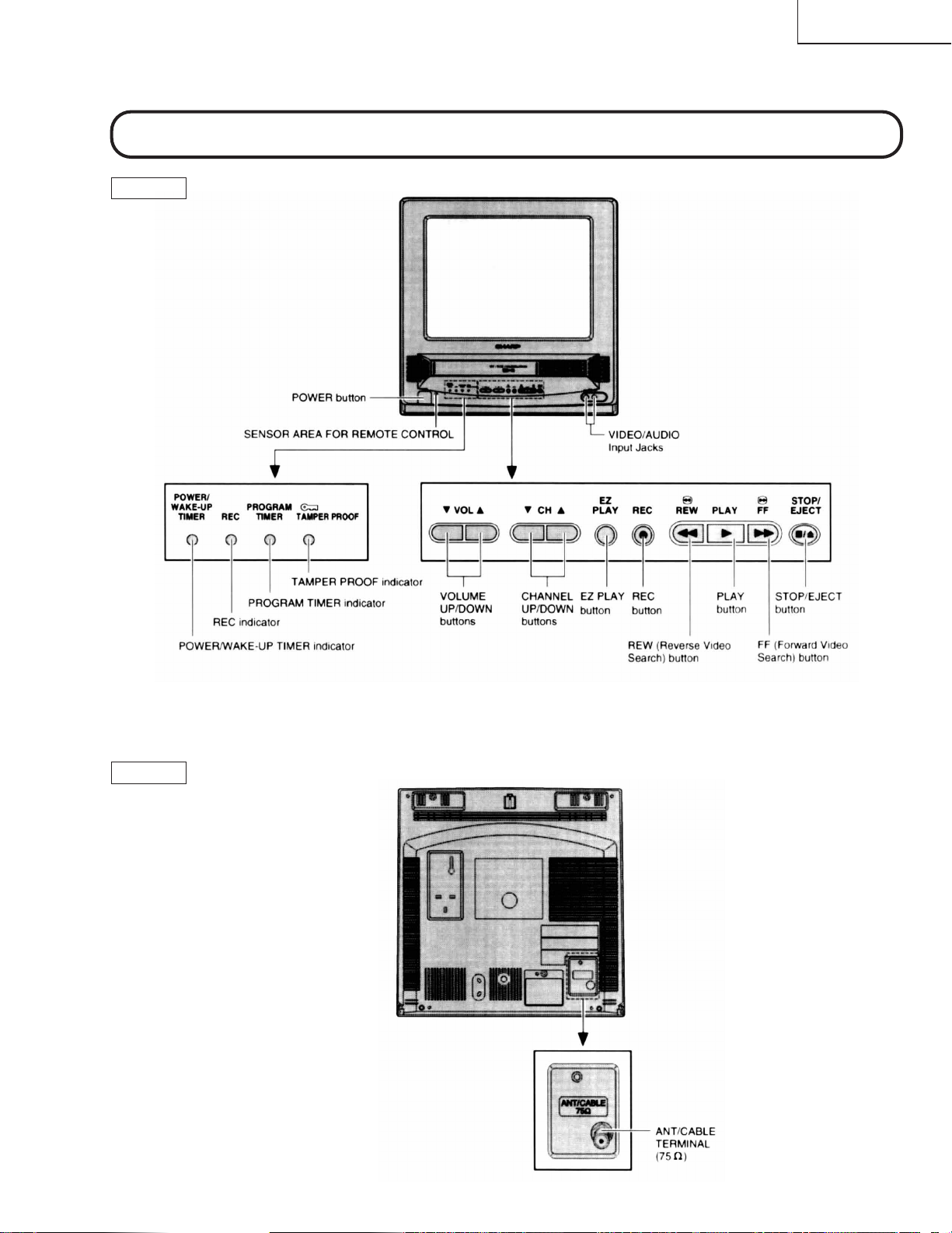
Description Of Controls
FRONT
LOCATION OF USER'S CONTROL
REAR
13VT-K100/150
13VT-CK10
8
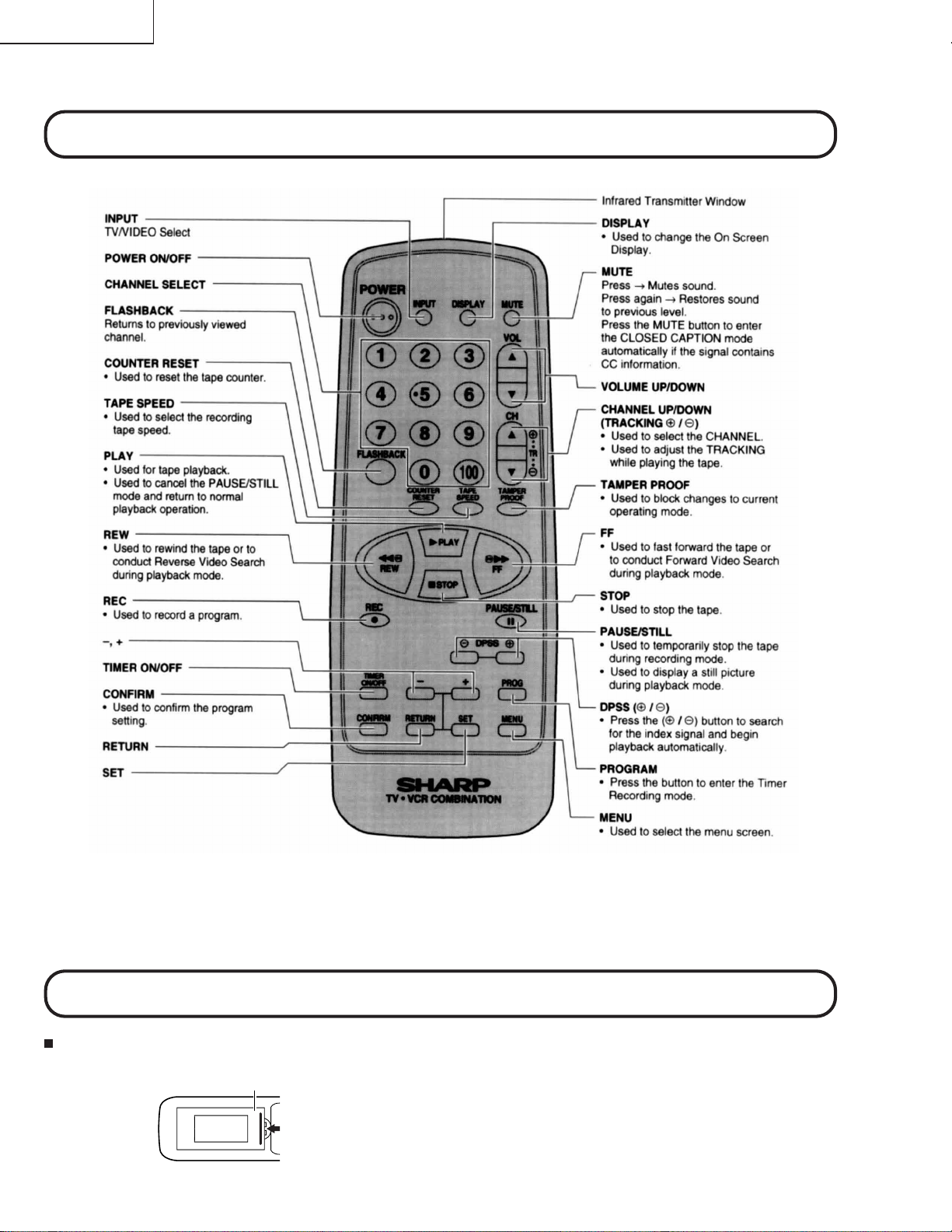
Location Of Control’s Buttons (Remote Control)
LOCATION OF USER'S CONTROL (Continued)
Remote Control Battery Installation
Before using the television, prepare the Remote Control.
Battery Cover
Pull Up
» Remote the battery cover as shown and insert two batteries (size
“AA”) making sure the polarity matches the (+) and (–) marks inside
the battery conpartment.

13VT-K100/150
13VT-CK10
9
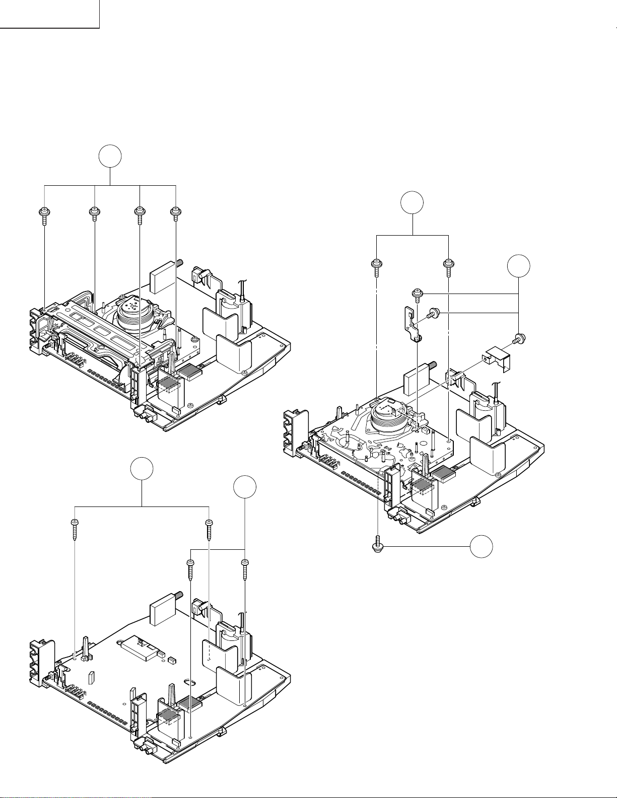
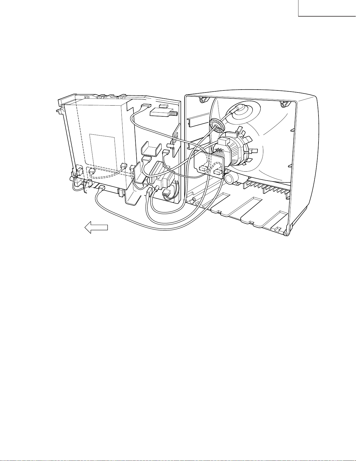
1. Remove the 7 rear cover fixing screws and detach the rear cover.
2. Take out the anode cap, CRT PWB, connectors K and M, coating earth, Speaker chip fixing screws and others.
3. Take out the main PWB unit and the VCR unit.
4. Remove the 5 VCR fixing screws, and detach the shielding case.
DISASSEMBLY AND REASSEMBLY
1
4
3
2
K
M
13VT-K100/150
13VT-CK10
10
5. Remove the 4 cassette housing control fixing screws, and detach the cassette housing control.
6. Remove the 2 mechanism chassis angle fixing screws, and remove the 1 head amp shielding case fixing screw.
7. Remove the 3 mechanism chassis fixing screws, and detach the mechanism chassis from the main PWB.
8. Remove the 2 main PWB fixing screws, and detach the main PWB.
9. Remove the 2 power PWB fixing screws, and detach the power PWB
DISASSEMBLY AND REASSEMBLY (Continued)
7
7
6
8
9
5
13VT-K100/150
13VT-CK10
11
DISASSEMBLY AND REASSEMBLY (Continued)
For servicing any of the components inside, disconnect the lead dressing holder. Position the main PWB unit upright
as shown below and connect the leads for starting the services.
GC
YC
M
K
S
YC
FRONT
SP
PO
PG
PG
S
GC
PO

13VT-K100/150
13VT-CK10
12
INSTALLATION AND SERVICE INSTRUCTIONS
Note: (1) When performing any adjustments to resistor controls and transformers use non-metallic
screwdriver or TV alignment tools.
(2) Before performing adjustment, TV set must be on at least 15 minutes.
HIGH VOLTAGE CHECK
High voltage is not adjustable but must be checked
to verify that the receiver is operating within safe
and efficient design limitations as specified checks
should be as follows:
1. Connect an accurate high voltage meter between
ground and anode of Picture tube.
2. Operate receiver for at least 15 minutes at 120V AC
line voltage, with strong air signal or properly tuned
in test signal.
3. Set to Service mode on, "Mute" and bus data 1(Y-
mute on).
4. The voltage should be approximately 25.4kV (at zero
beam). If a correct reading cannot be obtained,
check circuitry for malfunctioning components.
After the voltage test, "Mute" and bus data "0" (Y-
mute off).
CIRCUIT PROTECTION
The receiver is protected by a 4.0A fuse (F701), mounted
on PWB-A, wired into one side of the AC line input.
X-RADIATION PROTECTOR CIRCUIT
TEST
After service has been performed on the horizontal
deflection system, high voltage system, or B+ system,
test the X-Radiation protector circuit to ascertain proper
operation as follows:
1. Apply 120V AC using a variac transformer for
accurate input voltage.
2. Allow for warm up and using the remote controller,
set the brightness level and contrast level to
maximum.
3. Check the voltage of test point TP653. (It’s voltage
should be about 10.1V DC.)
4. Apply external 13.1V DC at TP653 by using an
external DC supply. The increased voltage will cause
the horizontal oscillator to stop and the TV to shut
off.
5. To re-start the oscillator, remove the external DC
power supply and short together TP651 and TP652.
Once the TV set operates normally again, remove
the short between TP651 and TP652.
13VT-K100/150
13VT-CK10
13
1. Service mode
Berfore putting unit into the service mode, check,
that customer adjustments are in the normal mode,
use the reset function in the video adjust menu to
ensure customer controls are in their proper (reset)
position.
To enter the service mode
Plug in a television set, during push S2507 (CH-up).
When successfuly entered, the service mode will be
displayed as shown in Figure A.
To exit service mode
Turn off the power or unplug the set.
2. Adjustment Item selection
Once in the service mode, press the channel up or
channel down button on the remote controller or at
the set (T able-A.). Select the item you wish to adjust.
3. Data number selection
Press the volume up or down button to adjust the
data number in the upper right hand side of the
screen.
PICTURE: 16 2
Figure A.
The K-series SHARP TV/VCR COMBINA TION have most of the analog setup adjustments eliminated. Coil and
variable resistor adjustments are now performed digitally by using the remote transmitter or set’s volume
and channel change function buttons.
Note: There are still a few analog adjustments in the K-series such as 120V adjust, focus, master screen
voltage and coils in the picture IF/detector circuit.
Follow the steps below whenever service adjustment is required. See table "B" to determine if service
adjustments are required.
13VT-K100/150
13VT-CK10
14
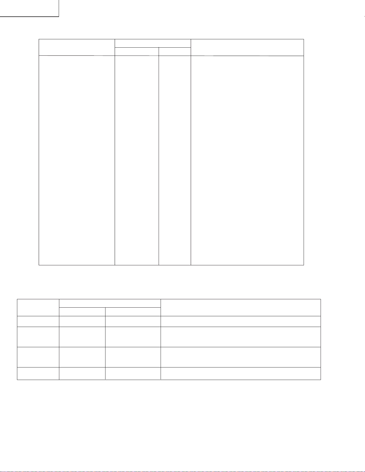
Table - B
PART
REPLACED
ADJUSTMENT
NECESSARY UNNECESSARY
NOTE
IC2001 X
IC401 X
IC2101 X
CRT X
ADJUSTMENT
ITEM
DATA
INTIAL VALUE RANGE
ADJUSTMENT
COMMENTS
*No adjustment is required due to proper setting being made by IC2001 automatically.
Table - A
PICTURE 16 0~63
TINT 39 0~77
COLOR 13 0~63
BRIGHT 32 0~63
SHARPNESS 7 0~13
VERTICAL PHASE 0 0~7
H-PHASE 20 0~31
RF-AGC 18 0~63
V-AMP 32 0-63
PIF-VCO 40 0-127
R CUT-OFF 0 0~255
G CUT -OFF 0 0~255
B CUT-OFF 0 0~255
G GAIN 128 0-255
B GAIN 128 0-255
Y-MUTE 0 0-2 "0"= Normal raster "1"= no"Y"
"2"= No Vertical
BALANCE 32 0~63
TEXT BOX 15 0-127
TEXT PICTURE 20 0-80
CCD LEVEL 7 0-10
OPTION 1 0-3
Data is stored in IC2101.
The adjustment is needed to compensate for characteristics
of parts including IC401.
Initial setting values are written from IC2001. Adjust for best
results.
Adjust items related to picture tube only.

13VT-K100/150
13VT-CK10
15
SERVICE ADJUSTMENT
VCO Adjustment
1. Connect a digital voltmeter between pin (44) of IC401
and ground.
2. Select a good local channel.
3. Enter the service mode. select adjustment item PIF-
VCO and data value "40".
4. Adjust the VCO coil L202 so that the digital voltmeter
reads 2.5 volts.
5. Adjustment is complete, remove the voltmeter, return
to "normal" mode.
RF AGC Adjustment
1. Have unit receive a good local channel.
2. Enter the service mode and select service adjustment
item "RF-AGC".
3. Set the data value to point where no noise or beat
appears.
4. Select another channel to confirm that no noise or
beat appears.
Note 1: You will have to come out of the service
mode to select another channel.
Note 2: Setting the data to "0" will produce a black
raster.
Screen Adjustment
1. Select a good local channel.
2. Enter the service mode and select service adjustment
item "COLOR" and set the data value to "0" to set
the color level to minimum. You may skip this step,
if you selected a B/W picture or monoscope pattern.
3. Select service adjustment item "Y-MUTE" and adjust
the data value to "1", this turns off the luminance
signal (Y-mute).
4. Select service adjustment item "BRIGHT" and set
the value to "32".
5. Adjust the master screen cotrol untill raster darkens
to the point where raster is barely seen.
6. Adjust service adjustments item "R-CUT OFF" red
"G-CUT OFF" green and "B-CUT OFF" blue to obtain
a good grey scale with normal whites at low
brightness level.
7. Select service adjustment item "MUTE" and reset
data to "0". Select service adjustment item "COLOR"
and reset data to obtain normal color level.
White Balance Adjustment
1. Have unit receive a good local channel.
2. Enter the service mode. Select service adjustment
item "COLOR" and set to "0" (minimum color).
"COLOR" does not have to be adjusted if you
selected a B/W picture or monoscope pattern.
3. Alternately adjust service adjustment data of "G
GAIN" and "B GAIN" untill a good grey scale with
normal whites is obtained.
4. Select service adjustment item "COLOR" and adjust
data to obtain normal color level.
Picture Adjustment
1. Have unit receive a good local channel.
2. Make sure the customer picture control is set to
maximum.
3. Enter the service mode and select service
adjustment item "PICTURE".
4. Adjust the data value to achieve normal contrast
range.
Tint Adjustment
1. Have unit receive a good local channel.
2. Set customer tint control to center of it’s range.
3. Enter the service mode and select service
adjustment item "TINT".
4. Adjust "TINT" data value to obtain normal flesh tones.
Color Adjustment
1. Have unit receive a good local channel.
2. Make sure the customer color control is set to center
position .
3. Enter the service mode and select service
adjustment item "COLOR".
4. Adjust "COLOR" data value to obtain normal color
level.
Brightness Adjustment
1. Have unit receive a good local channel.
2. Make sure the customer brightness control is set to
center position.
3. Enter the service mode and select service
adjustment item "BRIGHT".
4. Adjust "BRIGHT" data value to obtain normal
brightness level.
13VT-K100/150
13VT-CK10
16
Figure B.
Vertical-Size adjustment
1. Have unit receive a good local channel.
2. Enter the service mode and select service adjustment
item "V-AMP".
3. While observing the top and bottom of the screen,
adjust "V-AMP" data value to proper vertical size
and linearity.
Horizontal Position Adjustment
1. Have unit receive a good local channel.
2. Enter the service mode and select service adjustment
item "H-PHASE".
3. Adjust "H-PHASE" data value so that picture is
centered.
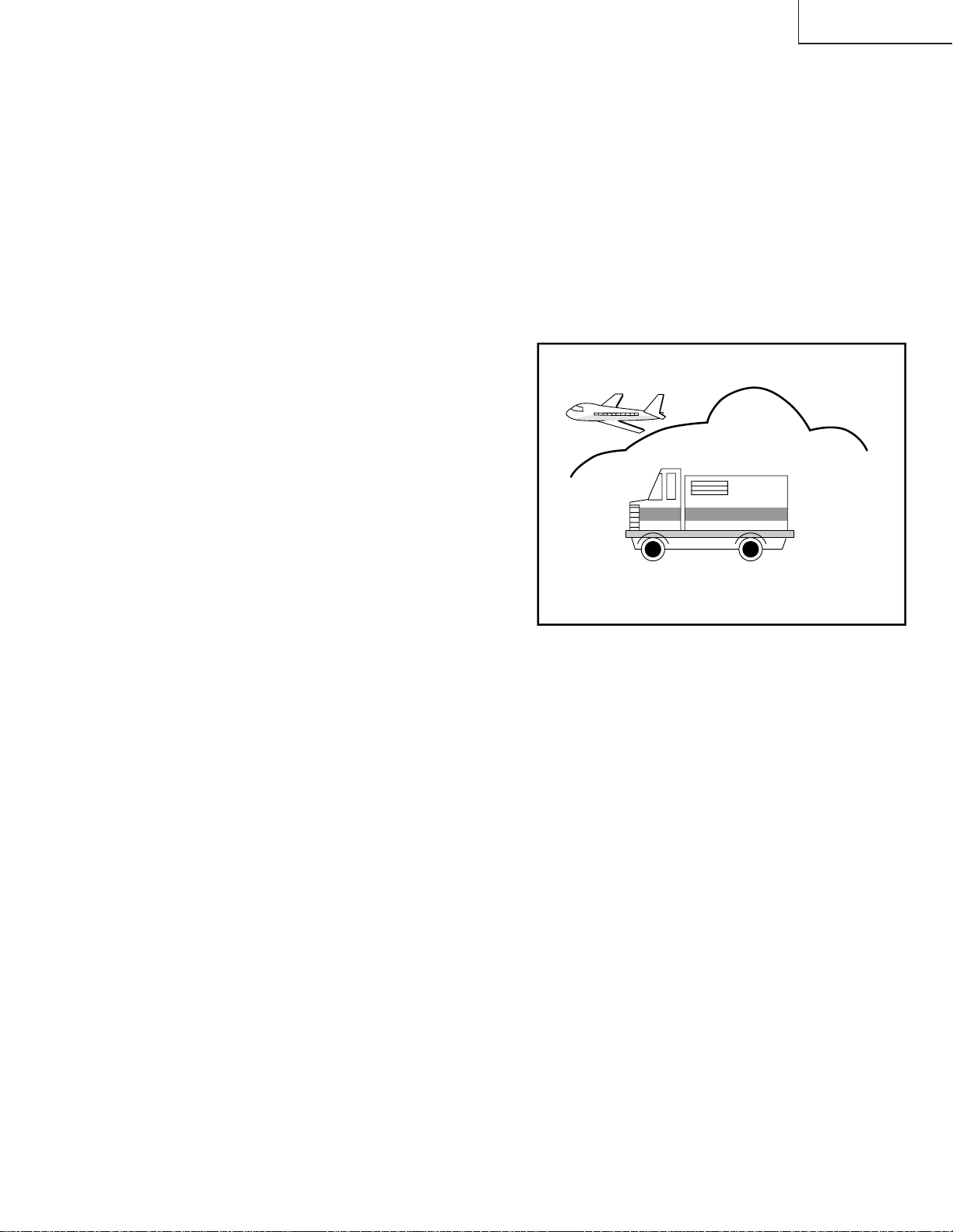
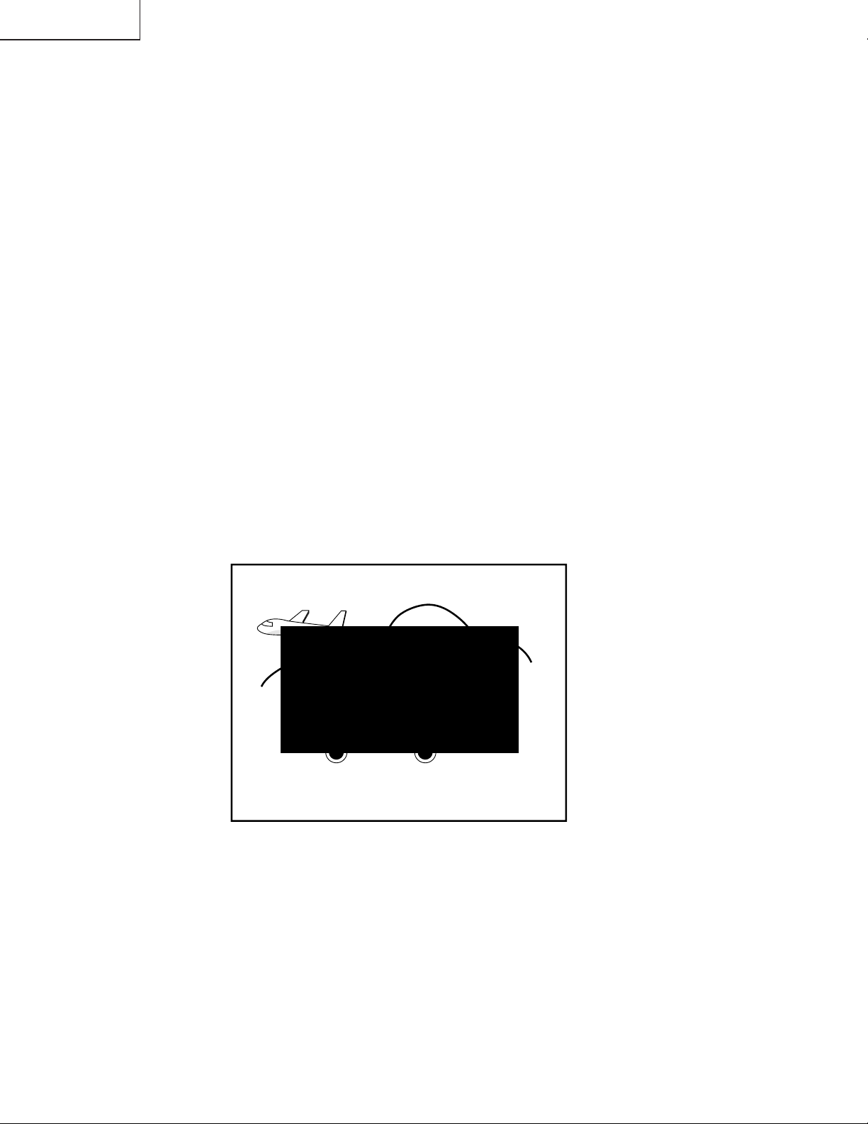
Caption Position Adjustment
(Horizontal)
1. Have unit receive a good local channel.
2. Enter the service mode and select service adjustment
item "TEXT BOX".
3. A black text box appears on the screen. (See Figure
B. below.)
4. Adjust "TEXT BOX" data value so that text box is
positioned in the center of the screen.
17
13VT-K100/150
13VT-CK10
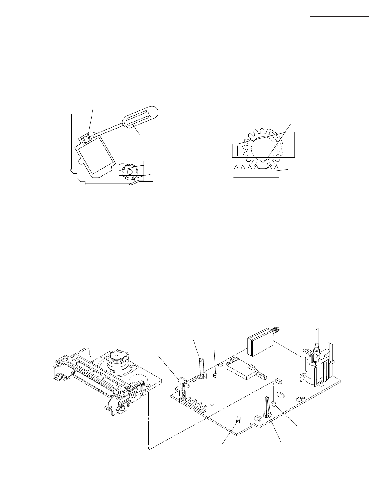
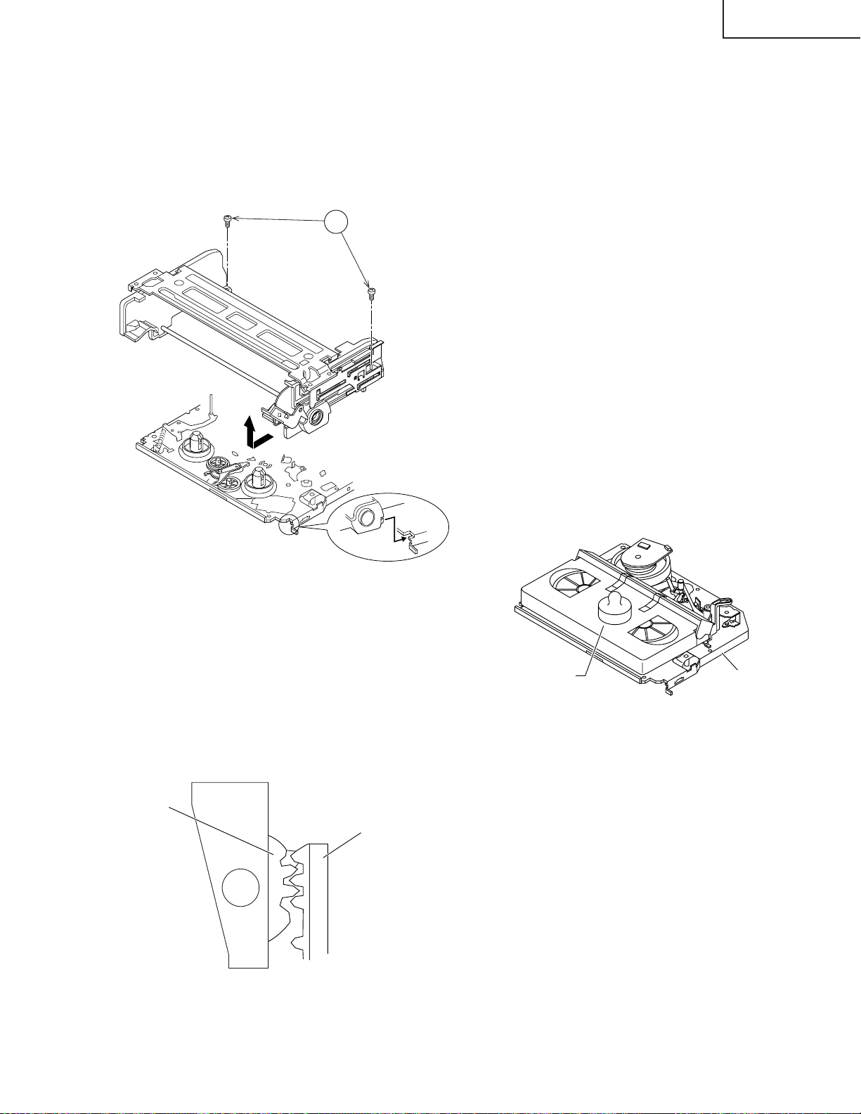
PRECAUTIONS IN REASSEMBLING
MOUTING THE CASSETTE CONTROLLER
Initial setting is indispensable before placing the cassette controller in the mechanism. The initial setting is made in two
ways;electrical and mechanical.
Electrical setting:
Make a short-circuit between TP7701 and TP7702 and be sure that the mechanism is back to its initial setting position (*1).
Now place the cassette controller in position.(This method is used when the mechanism has been already set on its PWB.)
COUPLING THE MECHANISM TO THE PWB
Match the mechanism’s projections with the two symbols (round reference and oval sub-reference) on the main PWB. Place the
mechanism straight down in position with due care so that the mechanism chassis’s outer edges should not damage any parts
nearby.
Tighten up the two screws (one for fixing the mechanism and the head amplifier shield, the other on the main PWB’s soldering side
and located near the loading motor) to fix the mechanism and main PWB. Reconnect the FFC cables (MH and AA, ME and AD,
Drum Unit and AH) between the mechanism and main PWB.
Parts to pay attention to:
Start and end sensors Q7703, Q7704
Record tip switch S7701
Take special care of the connectors (board to board; AC, AE, AL) between the mechanism and main PWB.
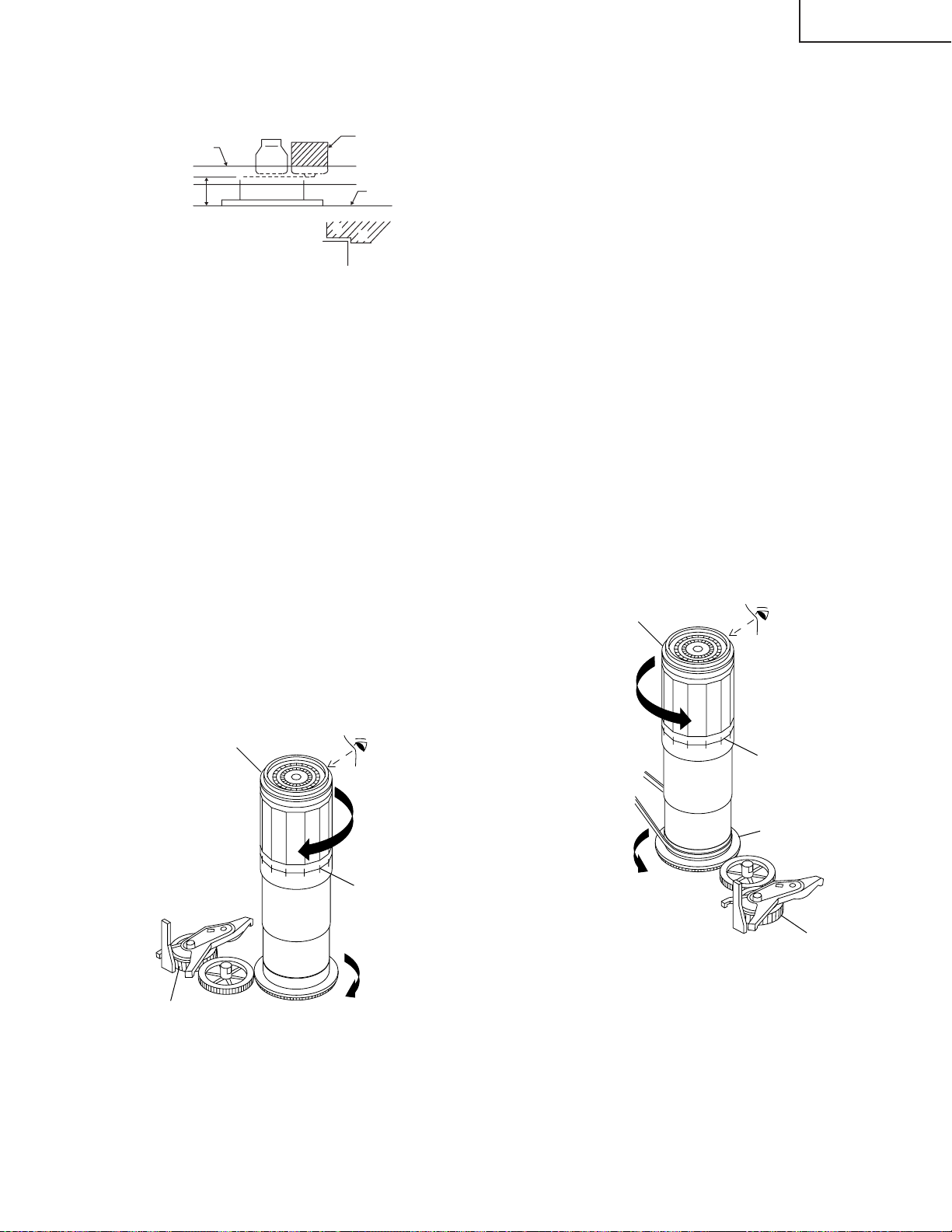
Mechanical setting:
Turn the loading motor’s pulley feed gear using a
screwdriver and be sure that the mechanism is back
to its initial setting position (*1). Now place the
cassette controller in position.(This method is appli-
cable for the mechanism alone.)
Pulley feed gear
Screwdriver
Large tooth
Casecon
drive gear
Drive angle of
cassette control
END SENSOR
REC TIP SW
AL Connector
AE Connector
AC Connector
START SENSOR
13VT-K100/150
13VT-CK10
18
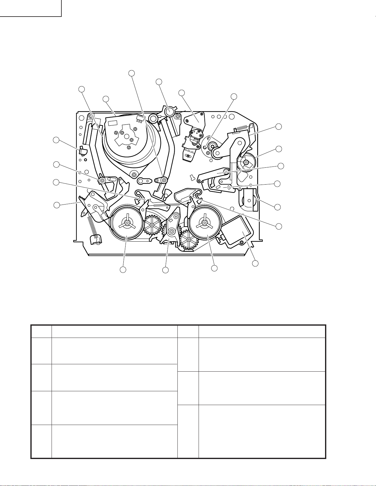
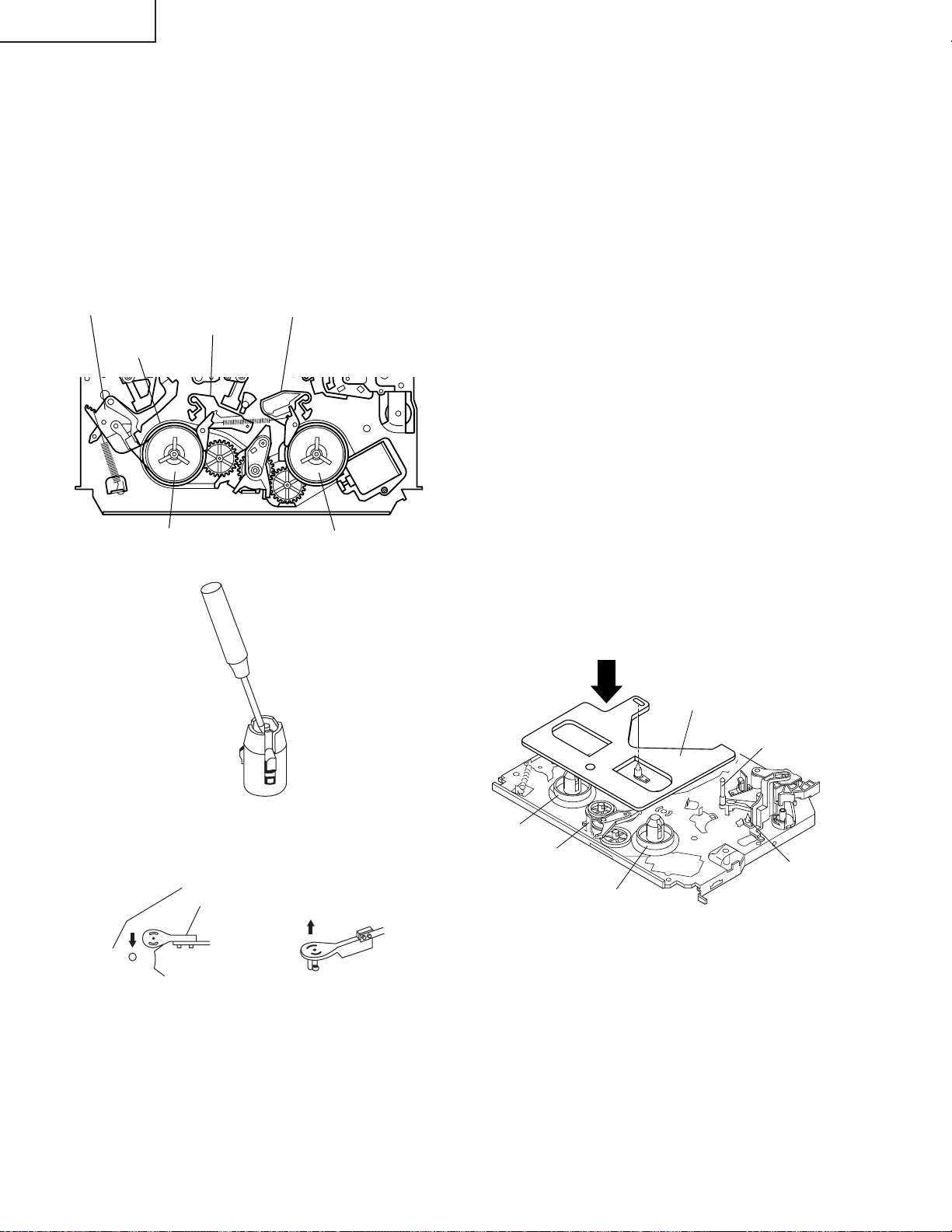
FUNCTION OF MAJOR MECHANICAL PARTS (TOP VIEW)
No. Function
No. Function
1. Full erase head ass’y
Erase the old recording on the tape in the record-
ing mode.
3. Tension arm ass’y
Detects the tension of tape while running, and
brakes the supply reel disk via the tension band.
7. Sup Main brake lever
Brakes the supply reel disk to prevent tape
slackening when the unit is stopped in fast for-
ward or rewind mode.
9. Main take-up brake lever
Brakes the take-up reel disk to prevent tape
slackening when the unit is stopped in fast for-
ward or rewind mode.
13. Reverse guide lever ass’y
Pulls out the tape and controls the tape drive train
height with the upper and lower guides.
16. Pinch roller lever ass’y
Press-fits the tape to the capstan during tape
running.
18. Loading motor
A motive power which drives the mechanism. It
transmits the power to the master cam and cas-
sette housing control ass'y.
Full Erase
Head
Supply Pole
Base Ass'y
Supply Reel
Disk
Sup Main
Brake Ass'y
Idler Wheel
Ass'y
Take-up
Reel Disk
Loading
Motor
Tension
Arm Ass'y
Fixing Guide
22
11
20
21
19
17
16
10
13
8
14
9
18
15
8
6
3
7
2
1
Drum Ass'y
Drum Motor
Take-up Pole Base Ass'y
A/C Head Ass'y
Pinch Roller
Lever Ass'y
Automatic Head Cleaner Ass'y
Pinch Drive
Cam
Pinch Drive
Lever Ass'y
Casecon
Drive Gear
Tu Main
Brake Ass'y
Reverse Guide
Lever Ass'y
19
13VT-K100/150
13VT-CK10
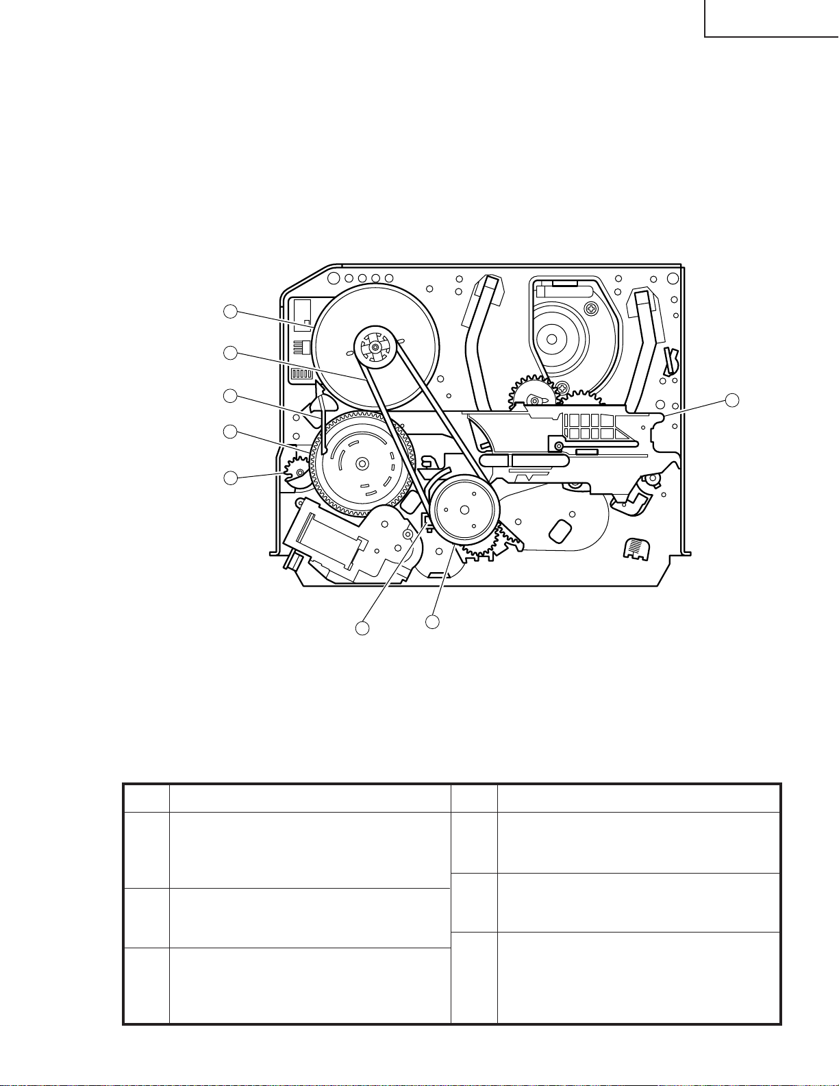
FUNCTION OF MAJOR MECHANICAL PARTS (BOTTOM VIEW)
No. Function
No. Function
6. Limiter pulley ass’y
Transmits the power of the capstan D.D. motor to
the reel disk via the drive idler.
8.
Shifter
Transmits the operation of the master cam to break
ass’y, Ioading gear, tension arm and clutch lever.
9.
Take-up loading gear
Shifts the take-up pole base and guide roller via the
loading gear T, and applies the tape around the drum
assembly, as well as transmits the power to the
loading gears.
1. Slow brake
Gets in contact with the capstan D.D. motor
linking to the master cam in the slow still mode,
and brakes it to a certain degree.
3. Capstan D.D. motor
A motive power which runs the tape. It transmits
the power via the Drive belt.
4. Drive belt
Transmits the power to run the tape to the Limiter
pulley.
Capstan D. D. Motor
Drive Belt
Slow Brake
Master Cam
Casecon Drive Gear
Clutch Lever
Limiter Pulley Ass'y
Shifter
3
4
1
2
7
5
6
8
13VT-K100/150
13VT-CK10
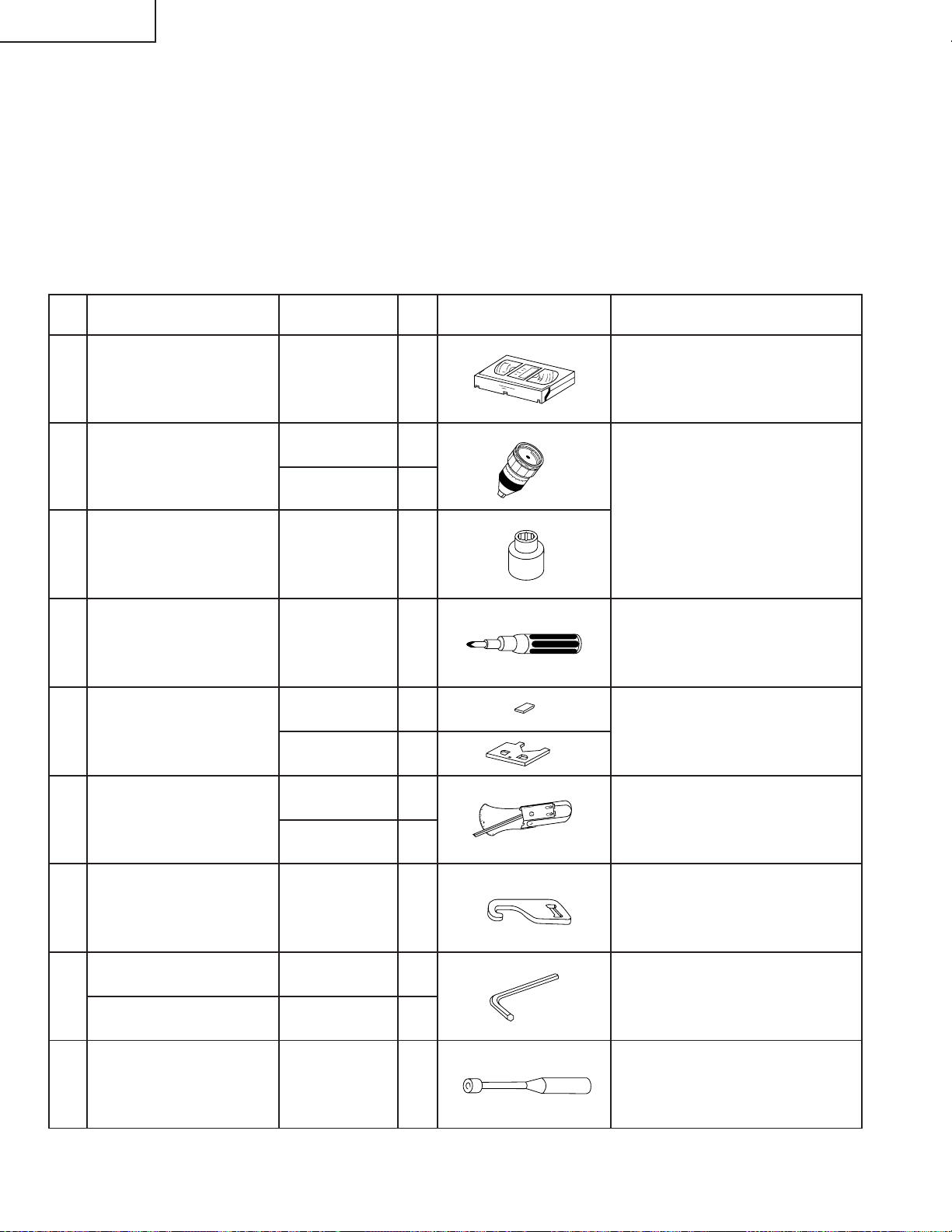
20
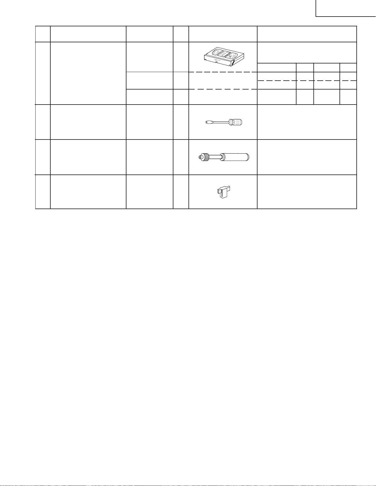
1. Torque Cassette Meter JiGVHT-063 CZ
JiGTG1200 CN
JiGMP0001 BY
No. Jig ltem Part No. Code Configuration Remarks
JiGTG0090 CM
3. Torque Gauge Head JiGTH0006 AW
5.
JiGRH0002 BR
JiGSG2000 BS
JiGSG0300 BF
6.
7. JiGADP003 BK
8.
9.
JiGDRiVER11055
AR
2.
Torque Gauge
Tension Gauge
These Jigs are used for checking
and adjusting the reel disk height.
When fixing any part to the threaded
hole using resin with screw, use the
jig. (Specified torque 5 kg)
This cassette torque meter is used
for checking and adjusting the torque
of take-up for measuring tape back
tension.
These Jigs are used for checking
and adjusting the torque of take-up
and supply reel disks.
Master Plane Jig and
Reel Disk Height
Adjusting Jig
Pinch pressing force
measuring jig
Reverse guide height
adjusting box driver
This Jig is used for height adjust-
ment of the reverse guide (for re-
verse guide height adjustment).
Hex Wrench (1.5 mm) JiGHW0015 AE
This Jig is used with the tension
gauge. Rotary transformer clearance
adjusting jig.
There are two gauges used for the
tension measurements, 300 g and
2.0kg.
Hex Wrench (1.2 mm) JiGHW0012 AE
4. Torque Driver JiGTD1200 CB
ADJUSTMENT, REPLACEMENT AND ASSEMBLY OF
MECHANICAL UNITS
The explanation given below relates to the on-site general service (field service) but it does not relates to the adjustment
and replacement which need high-grade equipment, jigs and skill. For example, the drum assembling, replacement and
adjustment service must be performed by the person who have finished the technical courses.
MECHANISM CONFIRMATION ADJUSTMENT JIG
So as to perform completely the mechanism adjustment prepare the following special jigs. So as to maintain the initial
performance of the machine the maintenance and check are necessary. Utmost care must be taken so that the tape is
not damaged. If adjustment needs any jig, be sure to sue the required jig.
These Jigs are used for loosening or
tightening special hexagon type
screws.
21
13VT-K100/150
13VT-CK10
12. JiGDRiVER-6 BM
11. JiGDRiVERH-4 AP
No. Jig ltem Part No. Code Configuration Remarks
This screwdriver is used for adjust-
ing the guide roller height.
VROATSV CD
These tapes are especially used for
electrical fine adjustment.
VROBBZGS CB
7k — 30µm
This Jig is used for height
adjustment of the reverse guide.
Guide roller height
adjustment drive
10.
Alignment Tape
X value adjustment
gear type screw driver
Reverse Guide Height
Adjusting Jig
525 Monoscope
Video Audio Hi-Fi Audio Track
525 Monoscope 7k — 58µm
NTSC Color Bar 1k — 58µm
13. JiGRVGH-F18 BU
For X value adjustment
13VT-K100/150
13VT-CK10
22
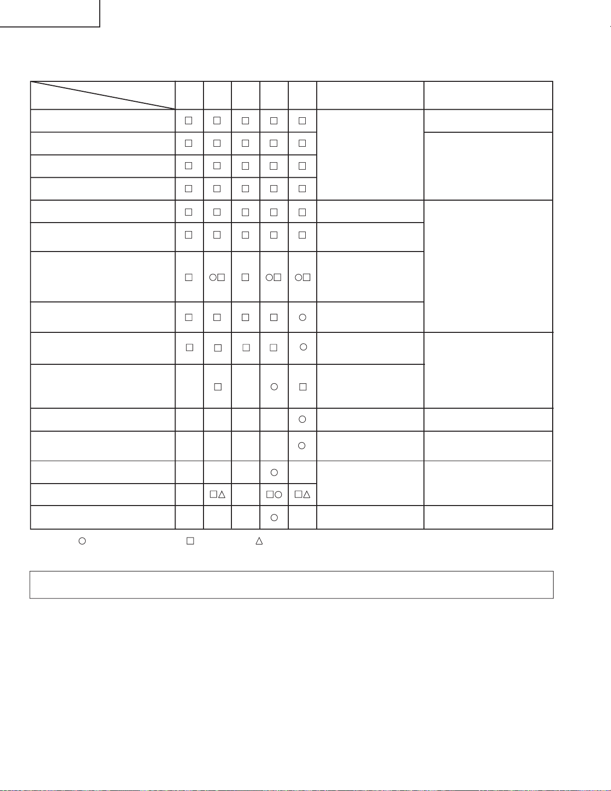
MAINTENANCE CHECK ITEMS AND EXECUTION TIME
Perform the maintenance with the regular intervals as follows so as to maintain the quality of machine.
Parts
Maintained
500
hrs.
1000
hrs.
1500
hrs.
2000
hrs.
Guide roller ass’y
Sup Guide Shaft
Retaining guide
Slant pole
Full-erase head Colour and beating
Clean tape contact part with
the specified cleaning liquid.
Abnormal rotation or significant vi-
bration requires replacement.
Remarks
Possible symptom
encountered
3000
hrs.
Lateral noises Head
occasionally blocked
Small sound or sound
distortion
Upper and lower drum ass’y
Poor S/N ratio, no color
Poor flatness of the enve-
lope with alignment tape
Clean rubber and rubber
contact area with the
specified cleaning liquid.
Pinch roller
No tape running, tape
slack
No tape running, tape
slack, no fast forward/
rewind motion
Reel belt
Cassette not loaded or
unloaded
Idler ass’y
Tension band ass’y Screen swaying
Loading Motor
Limiter pulley
Supply/take-up Main brake levers Tape slack
A/C head
No tape running, tape
slack
NOTE: : Part replacement. : Cleaning : Oil refilling
<Specified> Cleaning liquid Industrial ethyl alcohol
* This mechanism does not need electric adjustment with variable resistor. Check parts. If any deviation is found, clean
or replace parts.
Clean tape contact area with
the specified cleaning liquid.
Capstan D.D. Motor
No tape running, uneven
color
23
13VT-K100/150
13VT-CK10
Figure 1-1.
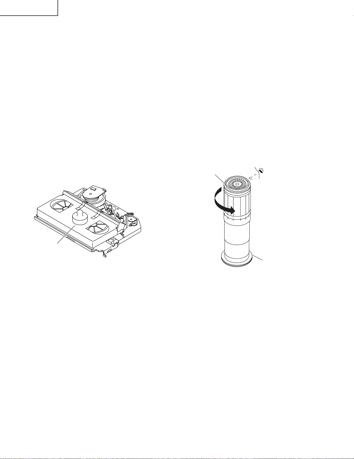
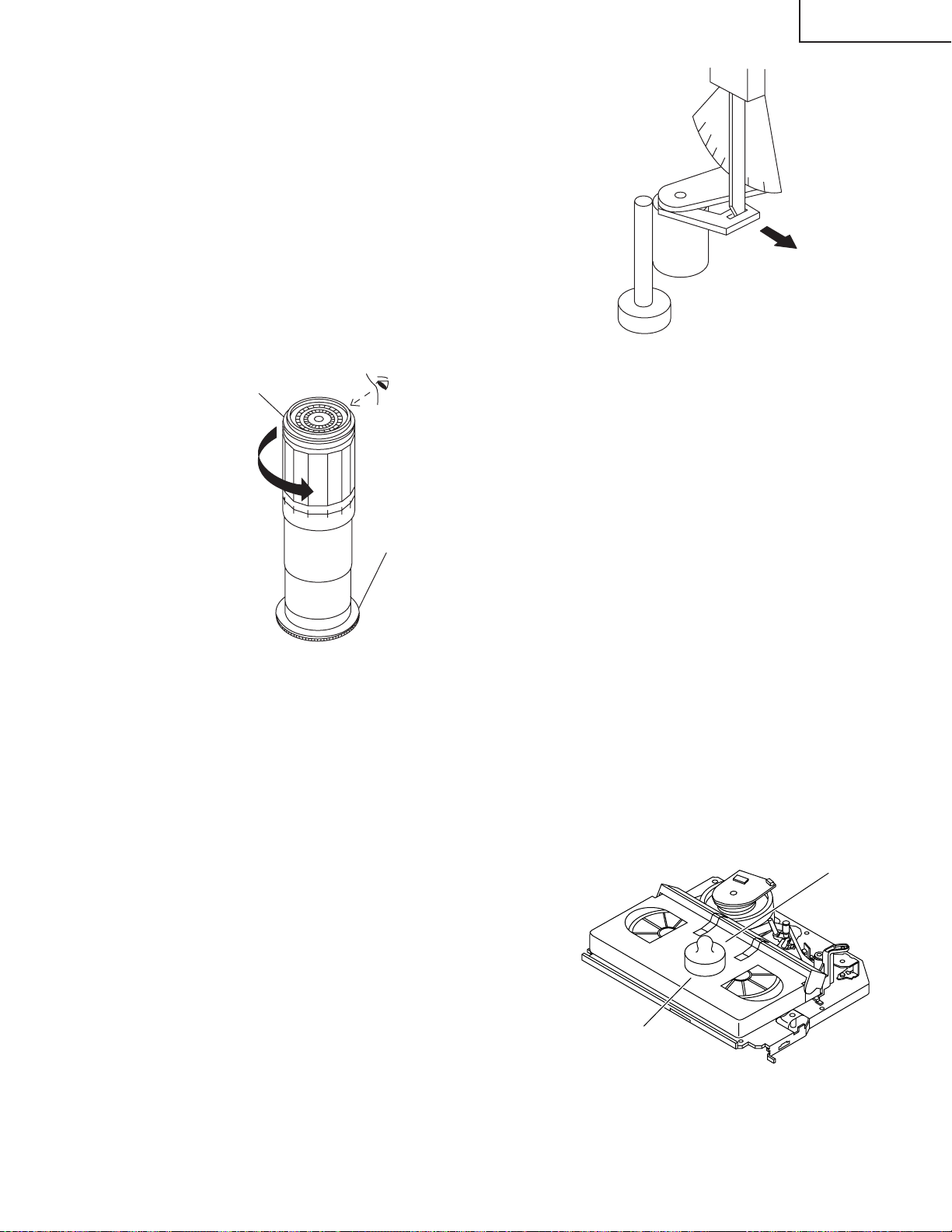
• Reassembly
1. Before installing the cassette housing control, short-
circuit TP7701 and TP7702 provided at the left of the
main PWB, prug in the power cord. The casecon drive
gear turns and stops when the positioning mark ap-
pears. Engage two teeth of casecon drive gear with
the three teeth of casecon drive angle gear, and set on
the mechanism chassis as shown below.
Figure 1-2.
2. Install in the reverse order of removal.
REMOVING AND INSTALLING THE CAS-
SETTE HOUSING
• Removal
1. In the cassette eject mode, remove the cassette.
2. Unplug the power cord.
3. Remove in the following numerical order.
a) Remove two screws 1.
b) Slide and pull up the cassette housing control.
1
Casecon
drive gear
Casecon drive
angle gear
500g
Mechanism chassis
Weight to prevent
float (500g)
Notes:
1. When fitting the S/E sensor holder to the cassette
controller frame L/R, take care.
2. Misengagement of teeth of casecon drive gear and
drive angle gear causes malfunction. (The cassette
cannot be set, load and ejection are repeated).
3. In the case when you use the magnet screw driver,
never approach the magnet driver to the A/C head, FE
head, and drum.
4. When installing or removing, take care so that the
cassette housing control and tool do not contact the
guide pin or drum.
5. After installing the cassette housing control once per-
form cassette loading operation.
TO RUN A TAPE WITHOUT THE CASSETTE
HOUSING CONTROL ASSEMBLY
1. Short-circuit TP7701 and TP7702.
2. Plug in the power cord.
3. Turn on the power.
4. Open the lid of a cassette tape by hand.
5. Hold the lid with two pieces of vinyl tape.
6. Set the cassette tape in the mechanism chassis.
7. Stabilize the cassette tape with a weight (500g) to
prevent floating.
8. Perform running test.
Figure 1-3.
Notes:
1. The weight should not be more than 500g.
2. Take care not to damage the tape when the Cassette
is set in the mechanism shassis or taken out of it
because the supply/take-up poles are shifted foward
the tape loading direction in the EJECT position.
13VT-K100/150
13VT-CK10
24
REEL DISK REPLACEMENT AND HEIGHT
CHECK
• Removal
1. Remove the cassette housing control assembly.
2. Pull the tension band out of the tension arm ass'y.
3. Remove the Sup/Tu main brake ass'y.
4. Open the hook at the top of the reel disk, and remove
the reel disk.
Note:
Take care so that the tension band ass'y and main brake
ass'y (especially soft brake) are not deformed.
Figure 1-4.
Note:
When the tension band ass'y is pressed in the direction
of the arrow for removal, the catch is hard to be deformed.
Figure 1-5.
• Reassembly (Supply reel disk)
1. Clean the reel disk shaft and apply grease (SC-141) to
it.
2. Match the phases of reel disk and reel relay gear, and
set the new reel disk.
3. After checking the reel disk height, wind the tension
band ass'y around the reel disk, and insert into the hole
of tension arm ass'y.
4. Assemble the Sup main brake ass'y.
Notes:
1. When installing the reel disk, take due care so that the
tension band ass'y is not deformed and grease does
no adhere.
2. Do not damage the Sup main brake ass'y. Be careful
so that grease does not adhere to the brake surface.
• Reassembly (Take-up reel disk)
1. Clean the reel disk shaft and apply grease (SC-141) to
it.
2. Align the phase of the reel disk to that of the reel relay
gear and to install a new take-up reel disk onto the
shaft.
3. Check the reel disk height and reassemble the take-up
main brake ass'y.
Note:
1. Take care so that the Tu main brake ass'y is not
damaged. Take care so that grease does not adhere
the brake surface.
2. After reassembly, check the video search rewind back
tension (see page 27), and check the brake torque
(see page 29).
• Height checking and adjustment
Note:
1. Set the master plane with due care so that it does not
contact the drum.
2. When putting the master plane, shift the reverse guide
a little in the loading direction. Care must be taken
since excessive shift results in damage.
Tension arm ass'y
Supply reel disk
Take-up reel disk
Sup main brake ass'y
Tu main brake ass'y
Tension band ass'y
Master plane
Reverse
guide
Position
pin
Supply reel disk
Cassette lock
release shaft
Take-up reel disk
Figure 1-6.
Note:
• Check that the reel disk is lower than part A but higher
than part B. If the height is not correct, readjust the reel
disk height by changing the poly-slider washer under
the reel disk.
25
13VT-K100/150
13VT-CK10
Note:
Whenever replacing the reel disk, perform the height
checking and adjustment.
A
B
Figure 1-7.
Master plane
Reel disk height
adjusting jig
Mechanism chassis
Reel disk
10 ± 0.2mm
Reel disk
CHECKING AND ADJUSTMENT OF TAKE-
UP TORQUE IN FAST FORWARD MODE
• Remove the cassette housing control assembly.
• After short-circuiting TP7701 and TP7702 provided
at the left on the main PWB, plug in the power cord,
then turn on the power.
• Setting
1. Set a torque gauge to zero on the scale. Place it on the
take-up reel disk.
2. Press the FF button.
3. To calculate the remaining capacity of the play back
mode, slowly rotate the supply reel disk, and then shift
it into the forward mode.
• Checking
1. Turn the torque gauge slowly (one rotation every 2 to
3 seconds) by hand in the CW direction.
2. Make sure that the indication of torque gauge is not
less than 30mN·m (306gf·cm).
Torque gauge
30mN·m (306gf·cm)
or more
Supply reel disk
Idler ass'y
The gauge is held at
its maximum value.
(Red mark)
CCW
Notes:
1. Hold the torque gauge by hand so that it is not moved.
2. Do not keep the reel disk in lock state. Do not allow
long-time measurement.
CHECKING AND ADJUSTMENT OF TAKE-
UP TORQUE IN REWIND MODE
• Remove the cassette housing control assembly.
• After short-circuiting TP7701 and TP7702 pro-
vided at the left on the main PWB, plug in the
power cord, then turn on the power.
• Setting
1. Set a torque gauge to zero on the scale. Place it on the
supply reel disk.
2. Press the rewind button.
3. To calculate the remaining capacity, slowly rotate the
take-up reel disk, and then shift it into the rewind
mode.
• Checking
1. Turn the torque gauge slowly (one rotation every 2 to
3 seconds) by hand in the CCW direction.
2. Make sure that the indication of torque gauge is not
less than 30mN·m (306gf·cm).
Figure 1-9.
• Adjustment
1. If the rewind winding-up torque is less than the speci-
fied value, clean the capstan D.D. motor pulley, drive
belt, and limiter pulley with cleaning liquid, rewind
again, and check the winding-up torque.
2. If the winding-up torque is still out of range, replace the
drive belt.
• Adjustment
1. If the FF winding-up torque is less than the specified
value, clean the capstan D.D. motor pulley, drive belt,
and limiter pulley with cleaning liquid, and check again.
2. If the torque is less that the set value, replace the reel
belt.
Figure 1-8.
Torque gauge
30mN·m (306gf·cm)
or more
The gauge is held at
its maximum value.
(Red mark)
Idler ass'y
CW
13VT-K100/150
13VT-CK10
26
Notes:
1. Hold the torque gauge by hand so that it is not moved.
2. Do not keep the reel disk in lock state. Do not allow
long-time measurement.
CHECKING AND ADJUSTMENT OF TAKE-
UP TORQUE IN RECORD/PLAYBACK MODE
• Remove the cassette housing control assembly.
• After short-circuiting TP7701 and TP7702 provided
at the left on the main PWB, plug in the power cord.
• Turn on the power.
• Open the cassette torque meter lid, and fix it with
tape.
• Load the cassette torque meter into the unit.
• Put the weight (500g) on the cassette torque meter.
• Turn on the power switch.
• Press the picture record button, and set EP picture
record mode (x3).
Torque gauge
Supply reel disk
CCW
Set value EP6.9 ± 2.5mN⋅m (70 ± 25gf⋅cm)
500g
Cassette torque meter
Figure 1-10.
• Checking
1. Make sure that value is within the setting 6.9±2.5mN·m
(70±25gf·cm).
2. The winding-up torque fluctuates due to variation of
rotation torque of limiter pulley ass'y. Read the center
value of fluctuation as setting.
3. Set the EP record mode (x3) and make sure that the
winding-up torque is within setting.
• Adjustment
If the playback winding-up torque is not within the setting,
replace the limiter pulley assembly.
Note:
When the torque cassette is set, put a weight (500g) to
prevent rise.
CHECKING AND ADJUSTMENT OF TAKE-
UP TORQUE IN VIDEO SEARCH REWIND
MODE
• Remove the cassette housing control assembly.
• After short-circuiting TP7701 and TP7702 pro-
vided at the left on the main PWB, plug in the
power cord, then turn on the power.
• Setting
Press the playback button and rewind button to set the
video search rewinding mode.
• Checking
1. Place the torque gauge on the supply reel disk, and
turn it counterclockwise very slowly (one rotation every
1 to 2 seconds) and check that the torque is within the
set value 14.0 ± 3.9mN⋅m. (144 ± 40gf⋅cm)
Figure 1-11.
Note:
Surely put the torque gauge on the reel disk to measure.
If the torque gauge is raised, accurate measurement is
impossible.
• Adjustment
1. If the rewinding playback winding-up torque is not
within the setting, replace the limiter pulley assembly.
Note:
The winding-up torque fluctuates due to variation of
rotation torque of supply reel disk. Read the center value
of fluctuation as setting.
27
13VT-K100/150
13VT-CK10
CHECKING THE VIDEO SEARCH REWIND
BACK TENSION
• Remove the cassette housing control assembly.
• After short-circuiting TP7701 and TP7702 pro-
vided at the left on the main PWB, plug in the
power cord, then turn on the power.
• Checking
1. After pressing the play button, press the rewind but-
ton, and set the video search rewind mode.
2. Place the torque gauge on the take-up reel disk, and
turn it counterclockwise very slowly (one rotation every
2 to 3 seconds) and check that the torque is within the
set value 3.4±1.5mN⋅m (35±15gf⋅cm).
Pinch roller
Tension gauge
900 - 1,200g
Capstan shaft
Tension gauge adapter
Figure 1-12.
Torque gauge
Take-up reel disk
Notes:
Set the torque gauge securely on the take-up reel disk.
If it is not secure, the measurement will be incorrect.
CHECKING THE PINCH ROLLER PRESSURE
• Remove the cassette housing control assembly.
• After short-circuiting TP7701 and TP7702 pro-
vided at the left on the main PWB, plug in the
power cord, then turn on the power.
• Checking
Press the play button to set the playback mode.
CCW
500g
(T-120)
Weight to prevent
float (500g)
Figure 1-13.
Figure 1-14.
• Checking
1. Set a cassette tape, push the REC button to place the
unit in the SP record mode. Now check the tension
pole position.
1. Detach the pinch roller from the capstan shaft.
Do not separate excessively. Or the pinch lever and
pinch double action lever may disengage.
2. Engage the tension gauge adapter with the pinch
roller shaft, and pull in the arrow direction.
3. Gradually return the pinch roller, and measure the
pulling force when the pinch roller contacts the cap-
stan shaft.
4. Make sure that the measured value is within setting
0.9 to 11.8 N (900 to 1,200g).
CHECKING AND ADJUSTMENT OF TENSION
POLE POSITION
• Remove the cassette housing control assembly.
• After short-circuiting TP7701 and TP7702 pro-
vided at the left on the main PWB, plug in the
power cord, then turn on the power.
• Setting
1. Open the cassette tape (T-120), and fix with tape.
2. Set the cassette tape in loading state.
3. Put the weight (500g) on the cassette tape.
4. Make the adjustment with the beginning of a T-120
tape.
 Loading...