

Page 1

Pact Series
MasterPact MTZ - MicroLogic X Control Unit
User Guide
Pact Series offers world-class breakers and switches
DOCA0102EN-07
03/2021
www.se.com
Page 2

Legal Information
The Schneider Electric brand and any trademarks of Schneider Electric SE and its
subsidiaries referred to in this guide are the property of Schneider Electric SE or its
subsidiaries. All other brands may be trademarks of their respective owners.
This guide and its content are protected under applicable copyright laws and
furnished for informational use only. No part of this guide may be reproduced or
transmitted in any form or by any means (electronic, mechanical, photocopying,
recording, or otherwise), for any purpose, without the prior written permission of
Schneider Electric.
Schneider Electric does not grant any right or license for commercial use of the guide
or its content, except for a non-exclusive and personal license to consult it on an "as
is" basis. Schneider Electric products and equipment should be installed, operated,
serviced, and maintained only by qualified personnel.
As standards, specifications, and designs change from time to time, information
contained in this guide may be subject to change without notice.
To the extent permitted by applicable law, no responsibility or liability is assumed by
Schneider Electric and its subsidiaries for any errors or omissions in the informational
content of this material or consequences arising out of or resulting from the use of the
information contained herein.
Page 3

Table of Contents
Safety Information.......................................................................................7
About the Book............................................................................................9
Introduction to the MicroLogic X Control Unit ....................................... 12
Pact Series Master Range......................................................................... 13
MicroLogic X Control Unit: Presentation ..................................................... 14
EcoStruxure Power Commission Software ................................................. 22
EcoStruxure Power Device App................................................................. 23
Password Management ............................................................................26
MicroLogic X Control Unit: Optional Digital Modules .................................... 29
Go2SE Landing Page ...............................................................................32
MicroLogic X Control Unit: Purchasing and Installing a Digital
Module ....................................................................................................34
MicroLogic X Control Unit: Date and Time ..................................................38
MicroLogic X Control Unit: Power Supply.................................................... 40
MicroLogic X Control Unit: Firmware Update............................................... 46
MasterPact MTZ - MicroLogic X Control Unit
Using the MicroLogic X Human Machine Interface.............................. 48
MicroLogic X HMI Description.................................................................... 49
HMI Display Modes................................................................................... 52
Quick View Mode......................................................................................53
Tree Navigation Mode............................................................................... 57
Protection Setting Procedure.....................................................................64
Measures Menu .......................................................................................67
Alarms & History Menu .............................................................................72
Maintenance Menu ................................................................................... 74
Configuration Menu .................................................................................. 76
Protection Menu ....................................................................................... 79
Pop-up Event Messages ........................................................................... 85
Protection Functions................................................................................. 89
Introduction..............................................................................................90
Electrical Distribution Protection........................................................... 91
Setting Protection in Accordance With UL489SE Standard..................... 96
Standard Protection Functions................................................................... 99
Long-Time Overcurrent Protection (L or ANSI 49RMS/51).................... 100
Short-Time Overcurrent Protection (S or ANSI 50TD/51)...................... 104
Instantaneous Overcurrent Protection (I or ANSI 50) ........................... 107
Ground-Fault Protection (G or ANSI 50N-TD/51N)............................... 111
Earth-Leakage Protection (ANSI 50G-TD) .......................................... 115
Neutral Protection ............................................................................. 118
Dual Settings.................................................................................... 120
Fallback Settings Mode ..................................................................... 123
Zone Selective Interlocking (ZSI)........................................................ 125
Optional Protection Functions.................................................................. 129
Undervoltage Protection (ANSI 27)..................................................... 130
Overvoltage Protection (ANSI 59) ...................................................... 135
Under/Overfrequency Protection (ANSI 81)......................................... 139
Reverse Active Power Protection (ANSI 32P)...................................... 144
Ground-Fault Alarm (ANSI 51N/51G) ................................................. 148
DOCA0102EN-07 3
Page 4

MasterPact MTZ - MicroLogic X Control Unit
Setting Guidelines .................................................................................. 168
Metering Functions................................................................................. 186
Standard Metering Functions................................................................... 187
Optional Metering Functions.................................................................... 228
Energy Reduction Maintenance Settings (ERMS)................................ 151
IDMTL Overcurrent Protection (ANSI 51)............................................ 158
Directional Overcurrent Protection (ANSI 67) ...................................... 164
Protection Setting Guidelines ............................................................ 169
Setting the Long-Time Overcurrent Protection (L or ANSI 49RMS/
51)................................................................................................... 171
Setting the Short-Time Overcurrent Protection (S or ANSI 50TD/
51)................................................................................................... 174
Setting the Instantaneous Overcurrent Protection (I or ANSI
50)................................................................................................... 176
Setting the IDMTL Overcurrent Protection........................................... 177
Setting the Directional Overcurrent Protection (ANSI67) ...................... 181
Selectivity......................................................................................... 184
Measurement Accuracy in Accordance with IEC61557-12.................... 188
Measurement Characteristics ............................................................ 193
Measurement Availability................................................................... 199
Network Settings .............................................................................. 207
Real-Time Measurements ................................................................. 208
Calculating Demand Values............................................................... 212
Power Metering ................................................................................ 214
Power Calculation Algorithm.............................................................. 216
Energy Metering ............................................................................... 218
Total Harmonic Distortion................................................................... 220
Power Factor PF and cos φ Measurement .......................................... 223
Energy per Phase ............................................................................. 229
Individual Harmonics Analysis ........................................................... 231
Maintenance and Diagnostic Functions .............................................. 234
Standard Maintenance and Diagnostic Functions...................................... 235
Maintenance Tools............................................................................ 236
Assistance ....................................................................................... 237
Maintenance Schedule...................................................................... 238
Health State ..................................................................................... 242
Monitoring the Circuit Breaker ........................................................... 243
Monitoring the Tripping Circuit............................................................ 244
Monitoring the Internal Functioning of the MicroLogic X Control
Unit.................................................................................................. 247
Monitoring the Circuit Breaker Service Life.......................................... 252
Monitoring the MicroLogic X Control Unit Service Life .......................... 253
Monitoring the Opening/Closing Function ........................................... 254
Monitoring the Contact Wear ............................................................. 257
Monitoring the Load Profile ................................................................ 259
Monitoring the Operating Time........................................................... 260
Circuit Breaker Overview................................................................... 261
Optional Maintenance and Diagnostic Functions....................................... 262
Power Restoration Assistant Digital Module ........................................ 263
MasterPact Operation Assistant Digital Module ................................... 265
Waveform Capture on Trip Event Digital Module.................................. 267
4 DOCA0102EN-07
Page 5

MasterPact MTZ - MicroLogic X Control Unit
IEC 61850 for MasterPact MTZ.......................................................... 270
Modbus Legacy Dataset Digital Module.............................................. 272
Operation Functions............................................................................... 273
Control Modes........................................................................................ 274
Opening Function ................................................................................... 279
Closing Function..................................................................................... 283
Communication Functions..................................................................... 289
®
Bluetooth
NFC Communication .............................................................................. 293
USB On-The-Go (OTG) Connection......................................................... 295
USB Connection..................................................................................... 296
Cybersecurity Recommendations ............................................................ 298
Low Energy Communication ................................................... 290
Event Management ................................................................................ 301
Event Definition ...................................................................................... 302
Event Type............................................................................................. 304
Event Notifications.................................................................................. 309
Event Display ......................................................................................... 311
Event History.......................................................................................... 312
Event List............................................................................................... 314
Appendices .............................................................................................. 325
Appendix A ............................................................................................ 326
Licensing Information ........................................................................ 326
Appendix B ............................................................................................ 328
MicroLogic Xi Control Unit: Description............................................... 328
DOCA0102EN-07 5
Page 6

Page 7

Safety Information
The addition of this symbol to a “Danger” or “Warning” safety label indicates that an
electrical hazard exists which will result in personal injury if the instructions are not
followed.
This is the safety alert symbol. It is used to alert you to potential personal injury
hazards. Obey all safety messages that follow this symbol to avoid possible injury or
death.
DANGER indicates a hazardous situation which, if not avoided, will result in death or serious
injury.
!
DANGER
WARNING indicates a hazardous situation which, if not avoided, could result in death or
serious injury.
WARNING
!
CAUTION indicates a hazardous situation which, if not avoided, could result in minor or
moderate injury.
CAUTION
!
NOTICE is used to address practices not related to physical injury.
NOTICE
Important Information
Read these instructions carefully, and look at the equipment to become familiar
with the device before trying to install, operate, service, or maintain it. The
following special messages may appear throughout this documentation or on the
equipment to warn of potential hazards or to call attention to information that
clarifies or simplifies a procedure.
MasterPact MTZ - MicroLogic X Control Unit
Please Note
Electrical equipment should be installed, operated, serviced, and maintained only
by qualified personnel. No responsibility is assumed by Schneider Electric for any
consequences arising out of the use of this material.
A qualified person is one who has skills and knowledge related to the construction
and operation of electrical equipment and its installation, and has received safety
training to recognize and avoid the hazards involved.
DOCA0102EN-07 7
Page 8

MasterPact MTZ - MicroLogic X Control Unit
CYBERSECURITY SAFETY NOTICE
WARNING
POTENTIAL COMPROMISE OF SYSTEM AVAILABILITY, INTEGRITY, AND
CONFIDENTIALITY
• Change default passwords at first use to help prevent unauthorized access to
device settings, controls, and information.
• Disable unused ports/services and default accounts to help minimize
pathways for malicious attackers.
• Place networked devices behind multiple layers of cyber defenses (such as
firewalls, network segmentation, and network intrusion detection and
protection).
• Use cybersecurity best practices (for example, least privilege, separation of
duties) to help prevent unauthorized exposure, loss, modification of data and
logs, or interruption of services.
Failure to follow these instructions can result in death, serious injury, or
equipment damage.
8 DOCA0102EN-07
Page 9
About the Book
Document Scope
MasterPact MTZ - MicroLogic X Control Unit
The aim of this guide is to provide users, installers, and maintenance personnel
with the technical information needed to operate MicroLogic
MasterPact
™
MTZ circuit breakers.
™
X control units in
MicroLogic X control units exist in two ranges:
• Control units for IEC standard: MicroLogic 2.0 X, 5.0 X, 6.0 X, 7.0 X
• Control units for UL standard: MicroLogic 3.0 X, 5.0 X, 6.0 X
This guide applies to the following MicroLogic X control units.
Standard Control units Commercial reference
IEC MicroLogic 2.0 X LV847600
MicroLogic 5.0 X LV847602
MicroLogic 6.0 X LV847603
MicroLogic 7.0 X LV847604
UL MicroLogic 3.0 X LV848815
MicroLogic 5.0 X LV847609
MicroLogic 6.0 X LV847608
NOTE: The commercial reference is printed on the front face of the MicroLogic X control unit. It
also identifies the standard, IEC or UL.
NOTE: This guide also applies to MicroLogic™ Xi control units. A
MicroLogic Xi control unit is a MicroLogic X control unit without Bluetooth
®
Energy communication.
Low
Validity Note
Online Information
All the information related to the MicroLogic X control units presented in this
guide applies to MicroLogic Xi control units except information about Bluetooth
Low Energy communication.
The specific features of the MicroLogic Xi control units are described in the
appendix, page 328.
This guide applies to MicroLogic X control units:
• With firmware version 004.000.000 or greater
• With hardware version 001.000.000 or greater
For a MicroLogic X control unit with a lower firmware version, refer to
DOCA0144EN MasterPact MTZ - MicroLogic X Control Unit - Firmware Release
Note for a description of the new features and bugs fixed in subsequent firmware
versions.
If required, contact your Customer Care Centre to obtain the version of this guide
that corresponds to the firmware version of your MicroLogic X control unit.
The information contained in this guide is likely to be updated at any time.
Schneider Electric strongly recommends that you have the most recent and up-todate version available on www.se.com/ww/en/download.
The technical characteristics of the devices described in this guide also appear
online. To access the information online, go to the Schneider Electric home page at
www.se.com.
DOCA0102EN-07 9
Page 10

MasterPact MTZ - MicroLogic X Control Unit
Related Documents for IEC Devices
Title of documentation Reference number
MasterPact MTZ Catalogue LVPED216026EN
MasterPact MTZ1 - IEC Circuit Breakers and SwitchDisconnectors - User Guide
MasterPact MTZ2/MTZ3 - IEC Circuit Breakers and
Switch-Disconnectors - User Guide
MasterPact MTZ - IEC Circuit Breakers and SwitchDisconnectors - Maintenance Guide
MasterPact MTZ - Modbus Communication Guide DOCA0105EN
MasterPact MTZ - IEC 61850 Communication Guide DOCA0162EN
MasterPact, ComPact, PowerPact - Cybersecurity Guide DOCA0122EN
ULP System for MasterPact and ComPact (IEC Standard) User Guide
Enerlin'X IO - Input/Output Application Module for One IEC
Circuit Breaker - User Guide
Enerlin'X EIFE - Embedded Ethernet Interface for One
MasterPact MTZ Drawout Circuit Breaker - User Guide
Enerlin'X IFE - Ethernet Switchboard Server - User Guide DOCA0084EN
Enerlin'X IFE - Ethernet Interface for One IEC Circuit
Breaker - User Guide
Enerlin’X FDM128 - Ethernet Display for Eight Devices User Guide
Complementary Technical Information LVPED318033EN
MasterPact MTZ - MicroLogic X Control Unit - Firmware
Release Note
MicroLogic Trip Units and Control Units - Firmware History DOCA0155EN
DOCA0100EN
DOCA0101EN
DOCA0099EN
DOCA0093EN
DOCA0055EN
DOCA0106EN
DOCA0142EN
DOCA0037EN
DOCA0144EN
How Can I Reduce Vulnerability to Cyber Attacks? Cybersecurity System Technical Note
You can download these technical publications and other technical information
from our website at www.se.com/ww/en/download.
Related Documents for UL/ANSI Devices
Title of documentation Reference number
MasterPact MTZ - Circuit Breakers and Switches - Catalog 0614CT1701EN
MasterPact MTZ1 - UL Rated/ANSI Certified 800 to 1600 A
Circuit Breakers and Switches - User Guide
MasterPact MTZ2/MTZ3 - UL Rated/ANSI Certified 800 to
6000 A Circuit Breakers and Switches - User Guide
MasterPact MTZ - Modbus Communication Guide DOCA0105EN
MasterPact MTZ - IEC 61850 Communication Guide DOCA0162EN
MasterPact, ComPact, PowerPact - Cybersecurity Guide DOCA0122EN
ULP System (UL Standard) - User Guide 0602IB1503 (EN)
Enerlin'X IO - Input/Output Application Module for One UL
Circuit Breaker - User Guide
Enerlin'X EIFE - Embedded Ethernet Interface for One
MasterPact MTZ Drawout Circuit Breaker - User Guide
Enerlin'X IFE - Ethernet Switchboard Server - User Guide 1040IB1401 (EN)
0614IB1702EN
0614IB1701EN
0613IB1317 (EN)
DOCA0106EN
Enerlin'X IFE - Ethernet Interface for One UL Circuit
Breaker - User Guide
Enerlin’X FDM128 - Ethernet Display for Eight Devices User Guide
MasterPact MTZ - MicroLogic X Control Unit - Firmware
Release Note
0602IB1801EN
DOCA0037EN
DOCA0144EN
10 DOCA0102EN-07
Page 11

MasterPact MTZ - MicroLogic X Control Unit
Title of documentation Reference number
MicroLogic Trip Units and Control Units - Firmware History DOCA0155EN
How Can I Reduce Vulnerability to Cyber Attacks? Cybersecurity System Technical Note
You can download these technical publications and other technical information
from our website at www.se.com/ww/en/download.
DOCA0102EN-07 11
Page 12

MasterPact MTZ - MicroLogic X Control Unit
Introduction to the MicroLogic X Control Unit
What’s in This Part
Pact Series Master Range ..............................................................................13
MicroLogic X Control Unit: Presentation ...........................................................14
EcoStruxure Power Commission Software .......................................................22
EcoStruxure Power Device App....................................................................... 23
Password Management .................................................................................. 26
MicroLogic X Control Unit: Optional Digital Modules..........................................29
Go2SE Landing Page..................................................................................... 32
MicroLogic X Control Unit: Purchasing and Installing a Digital Module ................ 34
MicroLogic X Control Unit: Date and Time ........................................................ 38
MicroLogic X Control Unit: Power Supply .........................................................40
MicroLogic X Control Unit: Firmware Update .................................................... 46
12 DOCA0102EN-07
Page 13

Pact Series Master Range MasterPact MTZ - MicroLogic X Control Unit
Pact Series Master Range
Future-proof your installation with Schneider Electric’s low-voltage and mediumvoltage Pact Series. Built on legendary Schneider Electric innovation, the Pact
Series comprises world-class circuit breakers, switches, residual current devices
and fuses, for all standard and specific applications. Experience robust
performance with Pact Series within the EcoStruxure-ready switchgear, from 16 to
6300 A in low-voltage and up to 40.5 kV in medium-voltage.
DOCA0102EN-07 13
Page 14

MasterPact MTZ - MicroLogic X Control Unit MicroLogic X Control Unit: Presentation
MicroLogic X Control Unit: Presentation
MicroLogic X Control Units for IEC and UL Standards - Overview
MasterPact MTZ circuit breakers with MicroLogic X control units provide functions
of protection, metering, diagnostics, communication, and remote operation. The
control unit can be customized with optional Digital Modules, page 29.
MicroLogic X control units allow operation and monitoring of MasterPact MTZ
circuit breakers locally or remotely.
The MicroLogic X control units for IEC standard are:
• MicroLogic 2.0 X
• MicroLogic 5.0 X
• MicroLogic 6.0 X
• MicroLogic 7.0 X
The MicroLogic X control units for UL standard are:
• MicroLogic 3.0 X
• MicroLogic 5.0 X
• MicroLogic 6.0 X
Convention
Unless specifically indicated as follows, the information in this guide is valid for
both IEC and UL standards:
• Information indicated for MicroLogic 5.0 X IEC and MicroLogic 6.0 X IEC is
valid only for the IEC standard.
• Information indicated for MicroLogic 5.0 X UL and MicroLogic 6.0 X UL is
valid only for the UL standard.
For this guide, electrical phases described as phase 1, phase 2, phase 3 cover
both IEC standard and UL standard, with the following equivalence:
IEC standard UL standard
Phase 1 Phase a
Phase 2 Phase b
Phase 3 Phase c
Range of MicroLogic X Control Units for IEC Standard
The following table indicates the standard functions available on MasterPact MTZ
circuit breakers with MicroLogic X control units for IEC standard:
MicroLogic
2.0 X
Commercial reference LV847600 LV847602 LV847603 LV847604
Long-time overcurrent protection
(L)
Short-time overcurrent protection
(S)
Instantaneous overcurrent
protection (I)
Ground-fault protection (G)
14 DOCA0102EN-07
✔ ✔ ✔ ✔
– ✔ ✔ ✔
✔ ✔ ✔ ✔
– – ✔ –
MicroLogic
5.0 X
MicroLogic
6.0 X
MicroLogic
7.0 X
Page 15

MicroLogic X Control Unit: Presentation MasterPact MTZ - MicroLogic X Control Unit
Earth-leakage protection (V)
Neutral protection
Dual settings
Overcurrent and trip cause
indicators
Zone selective interlocking
Trip history
Setting change traceability
Embedded power meter class 1
Embedded diagnostics
MicroLogic
2.0 X
– – – ✔
✔ ✔ ✔ ✔
✔ ✔ ✔ ✔
✔ ✔ ✔ ✔
– ✔ ✔ ✔
✔ ✔ ✔ ✔
✔ ✔ ✔ ✔
✔ ✔ ✔ ✔
✔ ✔ ✔ ✔
MicroLogic
5.0 X
MicroLogic
6.0 X
NOTE: The commercial reference is printed on the front face of the
MicroLogic X control unit and also identifies the standard, IEC or UL.
Range of MicroLogic X Control Units for UL Standard
The following table indicates the standard functions available on MasterPact MTZ
circuit breakers with MicroLogic X control units for UL standard:
MicroLogic
7.0 X
MicroLogic
3.0 X
Commercial reference LV848815 LV847609 LV847608
Long-time overcurrent protection (L)
Short-time overcurrent protection (S)
Instantaneous overcurrent protection (I)
Ground-fault protection (G)
Earth-leakage protection (V)
Neutral protection
Dual settings
Overcurrent and trip cause indicators
Zone selective interlocking
Trip history
Setting change traceability
Embedded power meter class 1
Embedded diagnostics
✔ ✔ ✔
– ✔ ✔
✔ ✔ ✔
– – ✔
– – –
✔ ✔ ✔
✔ ✔ ✔
✔ ✔ ✔
– ✔ ✔
✔ ✔ ✔
✔ ✔ ✔
✔ ✔ ✔
✔ ✔ ✔
MicroLogic
5.0 X
MicroLogic
6.0 X
NOTE: The commercial reference is printed on the front face of the
MicroLogic X control unit and also identifies the standard, IEC or UL.
Communication
MicroLogic X control units support wireless and wired communication and enable
local and network communication.
Local communication includes:
• Wireless connection to a smartphone running the EcoStruxure Power Device
app, page 23 through:
DOCA0102EN-07 15
Page 16

MasterPact MTZ - MicroLogic X Control Unit MicroLogic X Control Unit: Presentation
◦ Bluetooth Low Energy
◦ NFC
• Wired connection via the mini USB port to:
◦ A smartphone running the EcoStruxure Power Device app, page 23
through USB OTG connection
◦ A PC running EcoStruxure Power Commission software
Network communication includes:
• Wired connection via the ULP port module (optional) to
◦ Ethernet communication network with Modbus TCP/IP and/or IEC 61850
protocols
◦ Serial Line communication network with Modbus-SL protocol
MicroLogic X Control Units in Smart Panels
MasterPact circuit breakers with MicroLogic X control units, in conjunction with
Enerlin’X, provide simple and reliable access to data from a smartphone or PC.
MicroLogic X control units communicate using:
• Modbus TCP/IP protocol on Ethernet through an IFE server, or an IFE or
EIFE interface
• Modbus TCP/IP and IEC 61850 protocols on Ethernet through an IFE or EIFE
interface
• Modbus-SL protocol through an IFM interface with reference LV434000 (IFM
interface with reference TRV00210 is not compatible with MasterPact MTZ
circuit breakers).
• Bluetooth Low Energy or NFC for a wireless connection to the EcoStruxure
Power Device app
• The mini USB port to connect to:
◦ A PC running EcoStruxure Power Commission software
◦ A smartphone running the EcoStruxure Power Device app (USB OTG
connection)
• A Com’X energy server and Ethernet to connect to the Internet
16 DOCA0102EN-07
Page 17

MicroLogic X Control Unit: Presentation MasterPact MTZ - MicroLogic X Control Unit
The following diagram shows how MicroLogic X control units communicate within
a digital system:
Ethernet
USB
USB OTG connection
A FDM128 Ethernet display for eight devices
B IFE/EIFE webpages
C Com’X energy server
D EIFE interface
E EcoStruxure Power Device app through Bluetooth Low Energy or NFC wireless
communication
F EcoStruxure Power Device app through USB OTG connection
G EcoStruxure Power Commission software
H Go2SE landing page
DOCA0102EN-07 17
Page 18

MasterPact MTZ - MicroLogic X Control Unit
MicroLogic X Control Unit: Description
Introduction
The MicroLogic X control unit includes:
• LEDs to monitor the status of the circuit breaker
• A local Human Machine Interface comprising a graphic display with colored
backlight, contextual buttons, and dedicated buttons
• LEDs to monitor the cause of trips and alarms
Control Unit Description
A Ready LED
B Service LED
C ERMS LED
D Graphic display screen
E NFC wireless communication zone
F Home button
G Three contextual buttons
H Escape button ESC
I Bluetooth LED
J Bluetooth activation button
K Test button for ground-fault and earth-
leakage protection (MicroLogic 6.0 X and
7.0 X)
L Test/Reset button for trip cause LEDs and
alarms
M Mini USB port under rubber cover
N Overload and trip cause LEDs
O Cover for internal battery
P VPS voltage power supply module (optional)
Q VPS LED to indicate that the VPS module is
supplying the control unit
R QR code to access product information
S Control unit identification number
T Control unit type
U Sensor plug with the rated current of the
circuit breaker
V Plastic cover
18 DOCA0102EN-07
Page 19
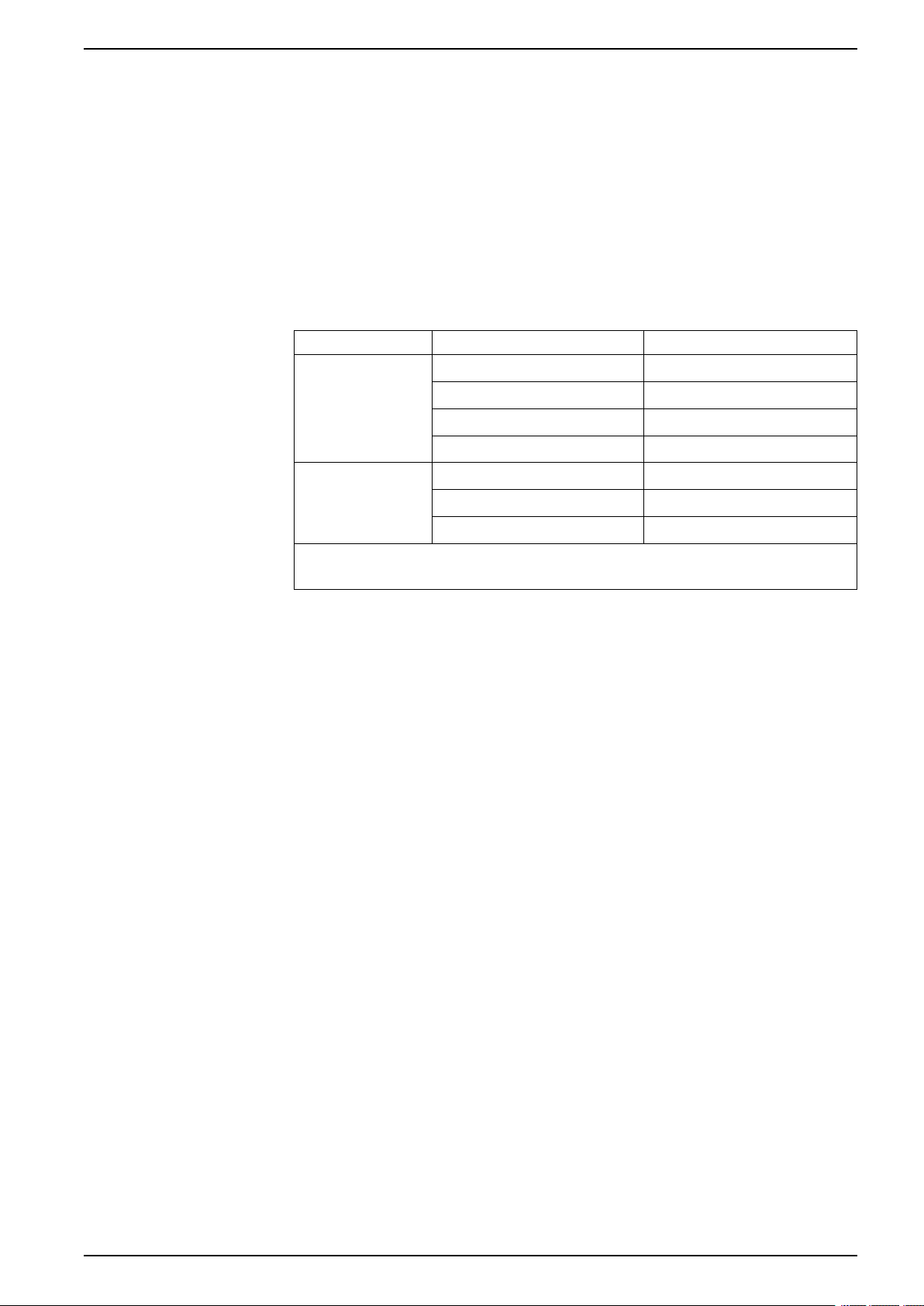
Status LEDs
MasterPact MTZ - MicroLogic X Control Unit
LED Description
Ready The Ready LED blinks slowly when the standard protection functions of the control
ERMS The ERMS (Energy Reduction Maintenance Setting) LED has the following statuses:
unit are operational.
The service LED alerts the user to the health state of the circuit breaker.
• Orange LED: medium severity detected alarm that requires non-urgent
maintenance action.
• Red LED: high severity detected alarm that requires immediate maintenance
action.
• Blue LED: ERMS engaged
• Off LED: ERMS disengaged
Display Screen with Contextual Buttons and Dedicated Buttons
The local HMI screen and buttons, page 49 are used to:
• Navigate the menu structure.
• Display monitored values.
• Access and edit configuration settings.
NFC Communication Zone
The NFC communication zone is used to establish an NFC connection, page 293
between a smartphone running the EcoStruxure Power Device app and the
MicroLogic X control unit. When the connection is established, the circuit breaker
operating data is automatically uploaded to the smartphone.
Bluetooth Activation Button and LED
The Bluetooth activation button is used to establish a Bluetooth Low Energy
connection, page 291 between a smartphone running the EcoStruxure Power
Device app and the MicroLogic X control unit. When the connection is established,
the circuit breaker can be monitored and controlled from the smartphone.
When the Bluetooth LED is blinking, it indicates that the MicroLogic X control unit is
in communication with a Bluetooth device.
Test Button
The test button is used to test the ground-fault protection for MicroLogic 6.0 X,
page 113 and the earth-leakage protection for MicroLogic 7.0 X, page 116.
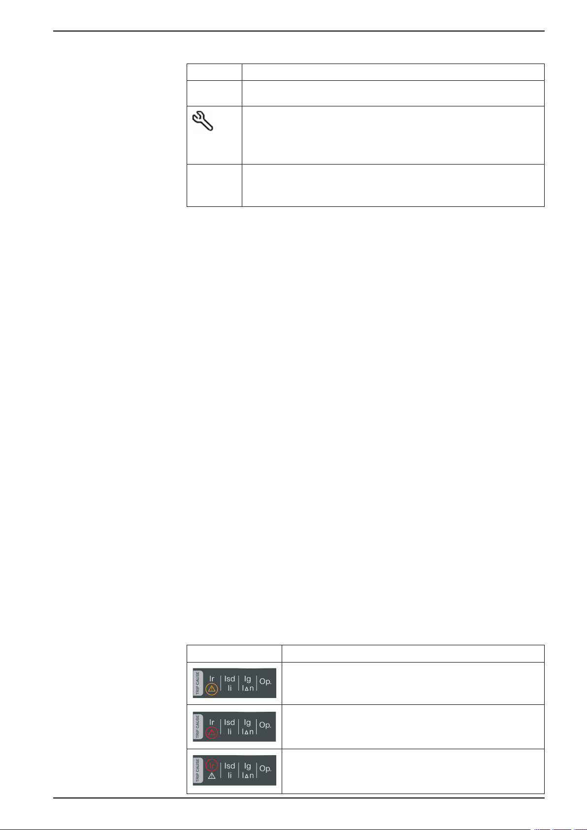
Overload and Trip Cause LEDs
The indications of the four trip cause LEDs depend on the type of MicroLogic X
control unit.
LEDs Description
• MicroLogic 2.0 X, 3.0 X, 5.0 X, 6.0 X, 7.0 X: Overload pre-alarm,
the load exceeds 90% and is lower than 105% of the Ir setting of
the long-time protection.
• MicroLogic 2.0 X, 3.0 X, 5.0 X, 6.0 X, 7.0 X: Overload alarm, the
load exceeds 105% of the Ir setting of the long-time protection.
• MicroLogic 2.0 X, 3.0 X, 5.0 X, 6.0 X, 7.0 X: Trip due to long-time
protection.
DOCA0102EN-07 19
Page 20
MasterPact MTZ - MicroLogic X Control Unit
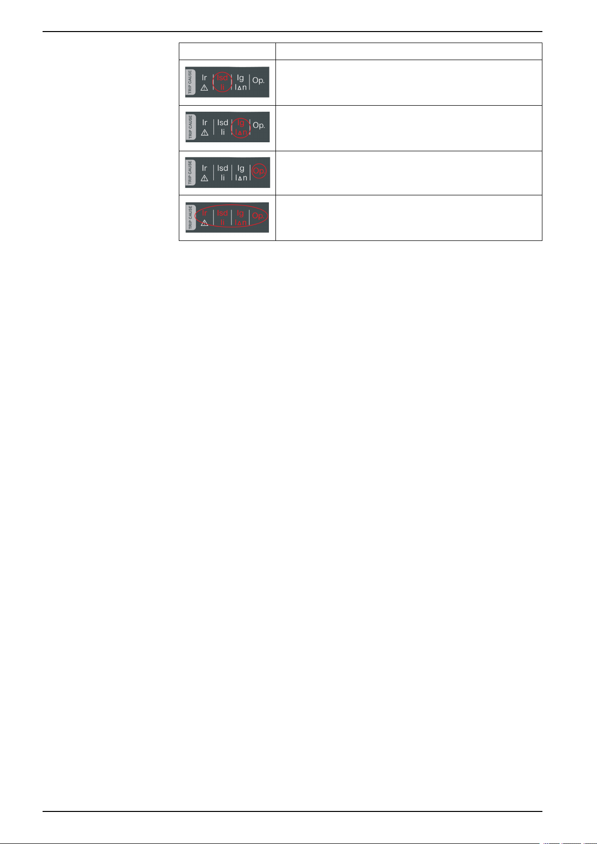
LEDs Description
NOTE: If the MicroLogic X control unit is not powered, the trip cause LEDs go
off after 4 hours. After this period, press the Test/Reset button to light them
again.
Test/Reset Button
• MicroLogic 2.0 X, 3.0 X: Trip due to instantaneous protection.
• MicroLogic 5.0 X, 6.0 X, 7.0 X: Trip due to short-time protection or
instantaneous protection.
• MicroLogic 2.0 X, 3.0 X, 5.0 X: Not applicable.
• MicroLogic 6.0 X: Trip due to ground-fault protection.
• MicroLogic 7.0 X: Trip due to earth-leakage protection.
• MicroLogic 2.0 X, 3.0 X, 5.0 X, 6.0 X, 7.0 X: Trip due to optional
protections.
• MicroLogic 2.0 X, 3.0 X, 5.0 X, 6.0 X, 7.0 X: Invalid control unit self
test.
Mini USB Port
The Test/Reset button performs the following functions:
• Test of the internal battery or check LED functionality: press and hold the Test/
Reset button for less than 3 seconds, the four trip cause LEDs switch off for
one second. One of the following results:
◦ The four trip cause LEDs switch on for two seconds: the battery is OK.
◦ The four trip cause LEDs flash sequentially for two seconds: the battery is
near the end of its life. Replace the battery.
◦ The four trip cause LEDs do not light: replace the battery.
NOTE: This test must be carried out immediately after the replacement of
the internal battery to check the correct functioning of the new battery. It
can then be carried out at any time in the life of the internal battery.
• Reset of the latched events: press and hold the Test/Reset button for more
than 3 seconds to reset the latched events. The trip cause LEDs and the
service LED switch off.
Remove the rubber cover of the mini USB port to connect the following devices:
• A Mobile Power Pack to supply power to the MicroLogic X control unit, page
44.
• A smartphone running the EcoStruxure Power Device app through USB OTG
connection, page 295.
• A PC running EcoStruxure Power Commission software, page 296.
NOTE: The MicroLogic X control unit does not support USB keys. Even if a
USB key is connected using an adapter, data is not transferred.
QR Code
When the QR code on the front face of a MicroLogic X control unit is scanned with
a smartphone running a QR code reader and connected to the Internet, the Go2SE
landing page is displayed, page 32. The landing page displays some information
about the device and a list of menus.
20 DOCA0102EN-07
Page 21

Control Unit Identification Number
The identification number is made up as follows:
• The serial number of the MicroLogic X control unit in the format
FFFFFFYYWWDLXXXX
• The commercial reference of the control unit in the format LV8•••••
Use the identification number to register your MicroLogic X control unit through
mySchneider app, the customer care mobile application.
Registering your MicroLogic X control unit enables you to keep your records up to
date and enables traceability.
Control Unit Type
This code indicates the type of MicroLogic control unit, page 14:
• The number (for example, 6.0) defines the types of protection provided by the
control unit.
• The letter (X) identifies the range of the control unit.
Internal Battery
MasterPact MTZ - MicroLogic X Control Unit
The internal battery, page 44 powers the trip cause LEDs and the main diagnostic
functions in the absence of any other power supply.
VPS Voltage Power Supply Module
The VPS module, page 41 provides an internal voltage supply to the MicroLogic X
control unit.
The VPS module is optional for MicroLogic 2.0 X, 3.0 X, 5.0 X, and 6.0 X. It is
installed as standard on MicroLogic 7.0 X.
Sensor Plug
The protection ranges depend on the rated current In, defined by the sensor plug,
page 91 present below the MicroLogic X control unit.
DOCA0102EN-07 21
Page 22

MasterPact MTZ - MicroLogic X Control Unit EcoStruxure Power Commission Software
EcoStruxure Power Commission Software
Overview
EcoStruxure Power Commission software helps you to manage a project as part
of testing, commissioning, and maintenance phases of the project life cycle. The
innovative features in it provide simple ways to configure, test, and commission
the smart electrical devices.
EcoStruxure Power Commission software automatically discovers the smart
devices and allows you to add the devices for an easy configuration. You can
generate comprehensive reports as part of Factory Acceptance Test and Site
Acceptance Test to replace your heavy manual work. Additionally, when the
panels are under operation, any change of settings made can be easily identified
by a yellow highlighter. This indicates the difference between the project and
device values, and hence provides a system consistency during the operation and
maintenance phase.
The EcoStruxure Power Commission software enables the configuration of the
MasterPact MTZ devices with:
• MicroLogic X control unit
• Communication interface modules: IFE, EIFE, and IFM interfaces
• IO application modules
• M2C output module
For more information, refer to the EcoStruxure Power Commission Online Help.
Key Features
The EcoStruxure Power Commission software is available at www.se.com.
EcoStruxure Power Commission software performs the following actions for the
supported devices and modules:
• Create projects by device discovery
• Save the project in the EcoStruxure Power Commission cloud for reference
• Upload settings to the device and download settings from the device
• Compare the settings between the project and the device
• Perform control actions in a secured way
• Generate and print the device settings report
• Perform a communication wiring test on the entire project and generate and
print test report
• View the communication architecture between the devices in a graphical
representation
• View the measurements, logs, and maintenance information
• Export Waveform Capture on Trip Event (WFC)
• View the status of device and IO module
• View the alarm details
• Buy, install, uninstall, or retrieve the Digital Modules
• Check the system firmware compatibility status
• Update to the latest device firmware
• Perform force trip test, and automatic trip curve tests with preconfigured or
custom test points
• Perform arc energy reduction tests in compliance with NEC 240.87(C)
• Declare MasterPact MTZ accessories
22 DOCA0102EN-07
Page 23

EcoStruxure Power Device App MasterPact MTZ - MicroLogic X Control Unit
EcoStruxure Power Device App
Presentation
EcoStruxure™Power Device app is a single mobile application with the necessary
information and capabilities to operate and efficiently maintain devices in the
EcoStruxure architecture.
The application enables you to connect to devices, including the following:
• MasterPact MTZ circuit breakers
• TeSys GV4 motor circuit breakers
• Easergy P3 protection relays
The application can be installed on a smartphone by downloading the application
from:
• Google Play Store for Android smartphones
• App Store for iOS smartphones
MasterPact MTZ Devices in EcoStruxure Power Device App
With the EcoStruxure Power Device app, a smartphone can be used with
MasterPact MTZ devices as the primary interface for day-to-day and critical case
maintenance. The MicroLogic X control unit is identified on the application by
scanning the QR code on the device.
When the EcoStruxure Power Device app is used in conjunction with a Digital
Module, additional functions are available:
• With the Power Restoration Assistant Digital Module, tutorials are available,
providing information about restoring power and identifying the causes of
trips.
• With the MasterPact Operation Assistant Digital Module, remote control of the
circuit breaker is available.
Wireless communication is available by Bluetooth and NFC communication. A
USB OTG connection is also available.
Using a Bluetooth Low Energy Connection
The MicroLogic X control unit must be powered to establish a Bluetooth Low
Energy connection.
Using EcoStruxure Power Device app with a Bluetooth Low Energy connection
gives access to and allows sharing of the information types organized in the
following tabs:
•
•
•
•
DOCA0102EN-07 23
Quick View: gives an overview of current values per phase, the health
state of the circuit breaker, and recent event history.
Metering: displays values of RMS current, RMS voltages, network, and
energy in real time.
Protection Setting: displays settings currently selected and allows
modification of settings.
Maintenance and Diagnostic:
◦ Displays maintenance reminder, service life, actuator wear, contact wear,
and diagnostic counters.
Page 24

MasterPact MTZ - MicroLogic X Control Unit EcoStruxure Power Device App
◦ Interprets contact wear to estimate the circuit breaker ability to isolate,
withstand rated duty, operate, and trip.
•
When Digital Modules, page 29 are installed on the MicroLogic X control unit,
additional information is available.
For more information, refer to the Bluetooth Low Energy connection procedure,
page 291.
Status and Control:
◦ Displays status of the circuit breaker.
◦ Allows opening and closing operations to be carried out when the
MasterPact Operation Assistant Digital Module is installed.
Using a USB OTG (On-The-Go) Connection
The MicroLogic X control unit can be powered by a smartphone using the USB
OTG connection, if necessary.
Using EcoStruxure Power Device app with a USB OTG connection gives access
to and allows sharing of the following information types organized in the following
tabs:
•
•
Quick View: gives an overview of current values per phase, the health
state of the circuit breaker, and recent event history.
Metering: displays values of current, RMS voltages, network, and
energy in real time.
•
•
•
When Digital Modules, page 29 are installed on the MicroLogic X control unit,
additional information is available.
For more information, refer to the USB OTG (On-The-Go) connection procedure,
page 295.
Protection Setting: displays settings currently selected and allows
modification of settings.
Maintenance and Diagnostic:
◦ Displays maintenance reminder, service life, actuator wear, contact wear,
and diagnostic counters.
◦ Interprets contact wear to estimate the circuit breaker ability to isolate,
withstand rated duty, operate, and trip.
Status and Control:
◦ Displays status of the circuit breaker.
◦ Allows opening and closing operations to be carried out when the
MasterPact Operation Assistant Digital Module is installed.
Using an NFC Connection
Connecting to EcoStruxure Power Device app with an NFC connection is always
possible, even when the MicroLogic X control unit is not powered. It gives access
to the following information:
• Information about the MicroLogic X control unit
• Last trip context: trip type; date and time of last trip; current values before trip
• Protection settings (display only)
24 DOCA0102EN-07
Page 25

EcoStruxure Power Device App MasterPact MTZ - MicroLogic X Control Unit
• Access to Power Restoration Assistant or MasterPact Operation Assistant
Digital Modules, page 30
For more information, refer to the NFC connection procedure, page 293.
DOCA0102EN-07 25
Page 26

MasterPact MTZ - MicroLogic X Control Unit Password Management
Password Management
General Description
Remote access to data on MicroLogic control units and the ULP modules of the
IMU is protected by password. Remote access includes:
• EcoStruxure Power Device app
• EcoStruxure Power Commission software
• FDM128 display
• The communication network
• IFE/EIFE webpages
The following four profiles are defined for remote access. An IMU has a different
password for each user profile:
• Administrator
• Services
• Engineer
• Operator
The following table shows the functions allowed for each user profile:
User profile Monitoring Com. and IP Settings Operation Reset
Administrator
Services
Engineer
Operator
No password
✔ ✔ ✔ ✔ ✔ ✔ ✔
✔ ✔ ✔ ✔ ✔ ✔ –
✔ ✔ ✔ ✔ – ✔ –
✔ ✔ – ✔ ✔ – –
✔ – – – – – –
counters
The following table describes the functions:
Function Description
Monitoring Read all settings, measurements, and data
Com. and IP Change communication settings and IP address
Settings Change all MicroLogic X control unit settings (except communication settings)
Operation • Open, close and reset circuit breaker
• Engage and disengage ERMS function
• Select active curve
• Inhibit circuit breaker closing
Reset counters • Reset minimum and maximum values
• Reset energy and operation counters
Test Recovery
function
Test Send test commands
Recovery
function
26 DOCA0102EN-07
• Reset Administrator password
• Force ERMS unlock
Page 27

Password Management MasterPact MTZ - MicroLogic X Control Unit
The following table indicates which functions can be performed through the
different remote access paths:
Function Remote access path
EcoStruxure
Power Device app
Monitoring
Com. and IP
Settings
Operation
Reset counters
Test
Recovery function
✔ ✔ ✔ ✔ ✔
– ✔ – – ✔
✔ ✔ ✔ ✔ ✔
✔ ✔ ✔ ✔ ✔
✔ ✔ – ✔ ✔
– ✔ – – –
✔ ✔ – – –
Default Passwords
EcoStruxure
Power
Commission
software
FDM128 display Communication
network
IFE/EIFE
webpages
WARNING
POTENTIAL COMPROMISE OF SYSTEM AVAILABILITY, INTEGRITY, AND
CONFIDENTIALITY
Change default passwords at first use to help prevent unauthorized access to
device settings, controls, and information.
Failure to follow these instructions can result in death, serious injury, or
equipment damage.
The default password for each user profile is as follows:
User profile Default password
Administrator ‘0000’ = 0x30303030
Services ‘1111’ = 0x31313131
Engineer ‘2222’ = 0x32323232
Operator ‘3333’ = 0x33333333
Changing a Password
A password can be changed with EcoStruxure Power Commission software, page
22.
Entering the current password for a given user profile is required to change the
password of this user profile. Entering the Administrator password enables you to
change the password of any user profile.
A password is composed of exactly 4 ASCII characters. It is case-sensitive and
the allowed characters are:
• Digits from 0 to 9
• Letters from a to z
• Letters from A to Z
DOCA0102EN-07 27
Page 28

MasterPact MTZ - MicroLogic X Control Unit Password Management
IMU Passwords
The MicroLogic X control unit and the ULP modules of the IMU must be protected
by the same passwords.
When using EcoStruxure Power Commission software to change a password, the
password is changed in the MicroLogic X control unit and the ULP modules of the
IMU.
It is compulsory to assign the current IMU passwords to a new module in the IMU
in the following cases:
• Addition of a new ULP module in the IMU.
• Replacement of the MicroLogic X control unit or of one of the ULP modules in
the IMU.
Use EcoStruxure Power Commission software to change the passwords of a new
module to the current IMU passwords.
Example:
An IO module is added to an IMU consisting of a MicroLogic X control unit and an
IFE interface. The IO module has the default passwords, for example,
Administrator = 0000.
The current IMU Administrator password = 4321.
Password Reset
Use EcoStruxure Power Commission software to change the default Administrator
password of the IO module (0000) to the IMU Administrator password (4321).
Modify the other default passwords of the IO module in the same way, changing
them to the passwords of the current IMU.
In the case that the Administrator password of the IMU is lost or forgotten, the
password can be reset to the default password with EcoStruxure Power
Commission software, page 22 and the support of the Schneider Electric
Customer Care Center.
28 DOCA0102EN-07
Page 29

MicroLogic X Control Unit: Optional Digital Modules MasterPact MTZ - MicroLogic X Control Unit
MicroLogic X Control Unit: Optional Digital Modules
Presentation
Digital Modules are optional modules that extend the features available across the
range of MicroLogic X control units.
Digital Modules can be purchased and installed on the MicroLogic X control unit
without changing the hardware or disrupting operations:
• When the MasterPact MTZ circuit breaker is initially ordered. They are preinstalled and functional when the MasterPact MTZ circuit breaker is delivered.
• At any time after the initial order by accessing the GoDigital marketplace,
page 34.
Check the compatibility of the MicroLogic X control unit firmware with Digital
Modules in the following tables. Update the firmware version of the MicroLogic X
control unit if it is not compatible with the Digital Module required, page 46.
Check the compatibility of communication interfaces (IFE/EIFE interfaces, IFM
interface) with Digital Modules in the tables, page 31. Update the firmware version
of the communication interface if it is not compatible with the Digital Module
required.
NOTE: The standard protection functions of a MicroLogic X control unit cannot
be upgraded by purchasing a Digital Module. For example, it is not possible to
convert a MicroLogic 5.0 X control unit to a MicroLogic 6.0 X control unit. This
type of upgrade requires replacing the MicroLogic X control unit.
Digital Modules for Protection Functions
The following table presents the Digital Modules for protection functions, with the
minimum MicroLogic X firmware version needed for the Digital Module to function:
Digital Module Commercial
ANSI 27/59 - Under/Over voltage
protection
ANSI 81 - Under/Over frequency
protection , page 139
ANSI 32P - Reverse active power
protection, page 144
ANSI 51N/51G - Ground-fault
alarm, page 148
reference
LV850012 Provides protection for generators, monitors phase-to-
LV850013 Provides protection for generators, monitors
LV850011 Provides protection for synchronous power generator,
LV850007 • Provides ground-fault alarm or earth-leakage
Description MicroLogic X
phase or phase-to-neutral voltages, and trips as
follows:
• When voltages are below setting range:
undervoltage protection, page 130
• When voltages are above setting range:
overvoltage protection, page 135
frequency, and trips as follows:
• When frequency is below setting range:
underfrequency protection
• When frequency is above setting range:
overfrequency protection
and trips when active power is negative and exceeds
the threshold.
alarm, independently from the ground-fault and
earth-leakage protections and with independent
settings
• Enables early detection of resistive ground faults
with fault currents increasing gradually up to the
settings of the ground-fault or earth-leakage
protection functions
firmware version
≥ 002.000.000
≥ 003.012.000
≥ 002.000.000
≥ 002.000.000
Energy Reduction Maintenance
Settings (ERMS), page 151
DOCA0102EN-07 29
LV850009 Reduces tripping time when internal arc flash occurs.
Used during periods of maintenance or presence of
personnel close to energized electrical equipment.
≥ 002.000.000
Page 30
MasterPact MTZ - MicroLogic X Control Unit MicroLogic X Control Unit: Optional Digital Modules
Digital Module Commercial
ANSI 51 - IDMTL overcurrent
protection, page 158
ANSI 67 - Directional short-time
overcurrent protection, page 164
reference
LV850037 Provides overcurrent protection based on the selected
LV850015 Provides overcurrent protection based on the direction
Description MicroLogic X
IDMTL (Inverse Definite Minimum Time Lag) tripping
curve.
of the short-circuit current.
Digital Modules for Metering Functions
The following table presents the Digital Modules for metering functions, with the
minimum MicroLogic X firmware version needed for the Digital Module to function:
Digital Module Commercial
Energy per phase, page 229 LV850002 Calculates and displays:
Individual harmonics analysis,
page 231
reference
LV850006 • Calculates and displays harmonics of voltages
Description MicroLogic X
• Imported and exported energy on each phase of
the network, at the point of measurement
• Active, reactive, and apparent energy per phase
and currents up to rank 40 (calculated every 200
ms according to IEC 61000-4-30)
• Provides average values of harmonics calculated
on a time period of 3 seconds
firmware version
≥ 004.000.000
≥ 004.000.000
firmware version
≥ 001.000.000
≥ 002.000.000
Digital Modules for Maintenance and Diagnostic Functions
The following table presents the Digital Modules for maintenance and diagnostic
functions, with the minimum MicroLogic X firmware version needed for the Digital
Module to function:
Digital Module Commercial
Power Restoration Assistant, page
263
MasterPact Operation Assistant,
page 265
Waveform capture on trip event,
page 267
Modbus legacy dataset, page 272 LV850045 Provides dataset compliant with the legacy format,
reference
LV850004 Provides assistance and guidance for:
LV850005 • Provides assistance to the maintenance operator
LV850003 • Automatically logs five cycles of phase and
Description MicroLogic X
firmware version
≥ 001.000.000
• Power restoration procedure
• Helping to determine potential causes of events
• Potential solutions for restoring power
≥ 001.000.000
in reclosing and opening the circuit breaker
• Displays circuit breaker status
Full benefits available when used with communicating
diagnostic voltage releases (MX, MN, XF).
≥ 001.000.000
neutral currents in the case of a trip
• Records the status of the circuit breaker (open/
closed/tripped) and ZSI signals
≥ 002.000.000
which can be used by existing Modbus drivers in
supervision software.
IEC 61850 for MasterPact MTZ,
page 270
LV850046 Provides data according to IEC 61850 (Ethernet-based
protocol).
≥ 004.000.000
30 DOCA0102EN-07
Page 31

MicroLogic X Control Unit: Optional Digital Modules MasterPact MTZ - MicroLogic X Control Unit
Compatibility of Digital Modules with Communication Interfaces
The following tables present the compatibility of Digital Modules with
communication interfaces.
For the following Digital Modules, the table indicates the minimum communication
interface firmware version needed for the Digital Module to function.
Digital Module Commercial
reference
Modbus legacy dataset LV850045 ≥ 003.007.000 ≥ 003.007.000 ≥ 003.001.000
IEC 61850 for MasterPact MTZ LV850046 ≥ 004.000.000
IFE/EIFE interface
firmware version
IFE server firmware
version
– –
IFM interface
firmware version
For the following Digital Modules, the table indicates the minimum communication
interface firmware version needed to access all data from the Digital Module
through a remote connection. With earlier communication interface firmware
versions, the Digital Module functions correctly. The data is not available via the
communication interfaces.
Digital Module Commercial
ANSI 27/59 - Under/Over voltage
protection
ANSI 81 - Under/Over frequency
protection
ANSI 32P - Reverse active power
protection
ANSI 51N/51G - Ground-fault alarm LV850007 ≥ 003.007.000 ≥ 003.007.000 ≥ 003.001.000
Energy Reduction Maintenance Settings
(ERMS)
ANSI 51 - IDMTL LV850037 ≥ 003.010.000 ≥ 003.010.000 ≥ 003.002.000
ANSI 67 - Directional short-time
overcurrent
Energy per phase LV850002 ≥ 003.006.000 ≥ 003.006.000 ≥ 003.000.000
reference
LV850012 ≥ 003.007.000 ≥ 003.007.000 ≥ 003.001.000
LV850013 ≥ 003.009.000 ≥ 003.009.000 ≥ 003.002.000
LV850011 ≥ 003.007.000 ≥ 003.007.000 ≥ 003.001.000
LV850009 ≥ 003.007.000 ≥ 003.007.000 ≥ 003.001.000
LV850015 ≥ 003.010.000 ≥ 003.010.000 ≥ 003.002.000
IFE/EIFE interface
firmware version
IFE server firmware
version
IFM interface
firmware version
Individual harmonics analysis LV850006 ≥ 003.007.000 ≥ 003.007.000 ≥ 003.001.000
Power Restoration Assistant LV850004 ≥ 003.006.000 ≥ 003.006.000 ≥ 003.000.000
MasterPact Operation Assistant LV850005 ≥ 003.006.000 ≥ 003.006.000 ≥ 003.000.000
Waveform capture on trip event LV850003 ≥ 003.006.000 ≥ 003.006.000 ≥ 003.000.000
DOCA0102EN-07 31
Page 32

MasterPact MTZ - MicroLogic X Control Unit Go2SE Landing Page
Go2SE Landing Page
Presentation
When the QR code on the front face of a MasterPact MTZ device is scanned with
a smartphone running a QR code reader and connected to the Internet, the
Go2SE landing page is displayed.
The landing page displays information about the device and a list of menus.
Landing Page Description
The landing page is accessible from Android and iOS smartphones. It displays the
same list of menus with slight differences in presentation.
The following example shows the landing page displayed on an Android
smartphone:
A Commercial reference of MicroLogic X control unit
B Type of MicroLogic X control unit
C Landing page menus. See the following menu
descriptions for details.
D Downloadable applications
Characteristics
Documentation
Selecting this menu gives access to a product datasheet with detailed information
about the MicroLogic X control unit.
Selecting this menu gives access to a sub-menu with the following options:
• Asset Life Cycle Documents: gives access to Safe Repository.
Safe Repository is a web service allowing documentation linked to assets to
be consulted, stored, and shared in a Schneider Electric environment. Access
to Safe Repository is restricted to authorized users.
Safe Repository gives access to the bill of materials of the MasterPact MTZ
circuit breaker.
• Technical Guidance at Glance: gives access to the MasterPact MTZ
technical publications, including:
◦ MasterPact MTZ - MicroLogic X Control Unit - User Guide
◦ MasterPact MTZ1 - Circuit Breakers and Switch-Disconnectors - User
Guide
32 DOCA0102EN-07
Page 33

Go2SE Landing Page MasterPact MTZ - MicroLogic X Control Unit
◦ MasterPact MTZ2/MTZ3 - Circuit Breakers and Switch-Disconnectors -
User Guide
◦ All the instruction sheets for MasterPact MTZ devices and MicroLogic X
control units
• Product Documentation: gives access to the MicroLogic X technical
publications
EcoStruxure Facility Expert App
Selecting this application gives access to the EcoStruxure Facility Expert mobile
application that can be downloaded on Android and iOS smartphones. For
smartphone compatibility, check on your application store.
EcoStruxure Facility Expert optimizes operations and maintenance, helping to
ensure business continuity, and provides insights to service providers or facility
managers.
EcoStruxure Facility Expert is a real-time collaborative technology available on
mobile devices and PCs that enables managers and maintenance personnel to be
connected with facilities and equipment. Information exchange between users is
simple and fast.
The QR code on MasterPact MTZ devices enables managers and maintenance
personnel to access the following automatic downloads:
• MasterPact MTZ device identifier.
• Technical documentation.
• The maintenance plan for the MasterPact MTZ device.
EcoStruxure Facility Expert enables managers and maintenance personnel to
access the maintenance plan for MasterPact MTZ devices.
EcoStruxure Facility Expert helps maintenance personnel to diagnose issues
remotely and manage maintenance efficiently by:
• Providing relevant information on critical assets.
• Sending immediate state of the equipment and detailed information helping
for diagnostics.
EcoStruxure Power Device App
Selecting this application gives access to the EcoStruxure Power Device app that
can be downloaded and installed on Android and iOS smartphones. For
smartphone compatibility, check on your application store.
mySchneider App
Selecting this application gives access to the Schneider Electric customer care
mobile application mySchneider app that can be downloaded on Android and iOS
smartphones. For smartphone compatibility, check on your application store. The
customer care application offers self-service instructions and easy access to
expert support and information.
DOCA0102EN-07 33
Page 34

MasterPact MTZ - MicroLogic X Control Unit
MicroLogic X Control Unit: Purchasing and Installing a Digital
MicroLogic X Control Unit: Purchasing and Installing a Digital Module
Presentation
A Digital Module can be purchased on GoDigital, which is the Schneider Electric
marketplace.
The following list indicates the prerequisites for purchasing an optional Digital
Module:
• Creation of a Schneider Electric user account with unique user name and
password by user
• Creation of a GoDigital customer account
• Setting up of a GoDigital user account by the user. The user must set up the
following predefined roles. Roles are cumulative.
◦ Admin: enables you to create user profiles and attribute roles.
◦ Buyer: enables you to select Digital Modules, add them to a cart, and
submit the cart for validation by the payer.
◦ Payer: enables you to validate or reject a cart, and check out the cart.
◦ Entitlement: enables you to access assets (control units) already added
and add a new control unit as an asset.
◦ Finance: enables you to manage invoices and payment details.
NOTE: The following role combinations are required to buy Digital Modules:
• Buyer + Payer (for control units already added to GoDigital)
• Buyer + Payer + Entitlement (for new control units)
Proceed as follows to purchase and install optional Digital Modules:
• Get the control unit identification number and access GoDigital, page 34.
• Select and purchase Digital Modules, page 35.
• Download and install the Digital Modules, page 36.
Module
Getting Control Unit Identification Number and Accessing
GoDigital
You can get the control unit identification number and/or access GoDigital on site
or off site using one of the following means:
• On site, by scanning the QR code on the front face of the MicroLogic X
control unit from a smartphone. The QR code identifies the MicroLogic X
control unit. Use the Share button to share the control unit information with
the person qualified to select and purchase Digital Modules.
• On site, from EcoStruxure Power Commission software with a PC connected
to the mini USB port of the MicroLogic X control unit. EcoStruxure Power
Commission software gets the control unit identification number and, from the
Buy button on the Digital Modules page, gives direct access to the GoDigital
webpage for PC.
• Off site, from EcoStruxure Power Commission software. This access can only
be used for a MicroLogic X control unit previously registered in the relevant
project. EcoStruxure Power Commission software gets the control unit
identification number and, from the Buy button on the Digital Modules page,
gives direct access to the GoDigital webpage for PC.
• Off site, and without identifying the MicroLogic X control unit, by pointing a
web browser at https://godigital.schneider-electric.com/ to display the
GoDigital webpage for PC. This access can only be used to purchase Digital
Modules for a second order for a previously identified MicroLogic X control
34 DOCA0102EN-07
Page 35

MicroLogic X Control Unit: Purchasing and Installing a Digital
Module MasterPact MTZ - MicroLogic X Control Unit
unit. The identification numbers of previously identified control units are listed
in the My Assets tab.
NOTE: When using the EcoStruxure Power Device app, if the functionality
required for a task is not present, a Get this functionality button provides a
link to the GoDigital webpage for PC offering the possibility to purchase the
relevant Digital Module. Share this link with the person qualified to select and
purchase Digital Modules.
Selecting and Purchasing a Digital Module in GoDigital
After accessing the GoDigital webpage for PC through one of the access points
described in the previous paragraph, the following list is displayed:
• See my assets. Click to buy a Digital Module for a MicroLogic X control unit
already registered. Refer to Buying a Digital Module for a Previously
Registered MicroLogic X Control Unit (see following table).
• Buy for one asset. Click to buy a Digital Module for one MicroLogic X control
unit. Refer to Buying a Digital Module for One MicroLogic X Control Unit,
page 35.
• Buy for multiple assets. Click to buy a Digital Module for more than one
MicroLogic X control unit or more than one Digital Module for one
MicroLogic X. Refer to Buying a Digital Module for Multiple MicroLogic X
Control Units, page 36.
NOTE: The cart can be saved for future validation and purchase.
Buying a Digital Module for a Previously Registered MicroLogic X
Control Unit.
Step Action
1 Click the See my assets button to purchase a Digital Module for a MicroLogic X control
unit which is already registered in GoDigital for a previous purchase.
Result: A list of MicroLogic X control units is displayed, identified by the control unit ID
number and commercial reference.
2 Select the MicroLogic X control unit for which you want to buy a Digital Module by
clicking Buy for this asset next to the MicroLogic X control unit selected.
3 Select the Digital Modules to purchase for your MicroLogic X control unit.
4 Submit the cart. The purchase is validated and the invoice, order confirmation, and a
link to the delivery package are sent by email.
NOTE: The validation of the purchase is possible only if the GoDigital customer
account has been created, page 34.
5
Click the link to download the delivery package and save it onto the PC to be used for
the installation of the Digital Module.
Buying a Digital Module for One MicroLogic X Control Unit
Step Action
1 Click the Buy for one asset button to purchase a Digital Module for a MicroLogic X
control unit which is not already registered in GoDigital for a previous purchase.
2 Fill in the serial number and commercial reference of your MicroLogic X control unit.
3 Click Submit.
Result: The screen displays a list of Digital Modules available for your MicroLogic X
control unit.
4 Select the Digital Modules to purchase for your MicroLogic X control unit.
DOCA0102EN-07 35
Page 36

MasterPact MTZ - MicroLogic X Control Unit
Step Action
5
6 Click the link to download the delivery package and save it onto the PC to be used for
Submit the cart. The purchase is validated and the invoice, order confirmation, and a
link to the delivery package are sent by email.
NOTE: The validation of the purchase is possible only if the GoDigital customer
account has been created, page 34.
the installation of the Digital Module.
Module
Buying a Digital Module for Multiple MicroLogic X Control Units
Step Action
1 Click the Buy for multiple assets button to purchase one Digital Module for multiple
MicroLogic X control units or multiple Digital Modules for one MicroLogic X control unit.
2 Click Download an example .xls or .xlsx file template.
3 Fill in the .xls file with the following information for the control units that you are buying
for:
• Control unit serial numbers
• Control unit commercial references
• Digital Module commercial references
NOTE: The .xls file supports a maximum of 20 lines.
MicroLogic X Control Unit: Purchasing and Installing a Digital
4 Upload the .xls file to GoDigital by clicking the Browse button.
Result: GoDigital checks the order to avoid duplicating purchases for the same
MicroLogic X control unit. If a duplication is detected, a message is displayed.
5
Submit the cart. The purchase is validated and the invoice, order confirmation, and a
link to the delivery package are sent by email.
NOTE: The validation of the purchase is possible only if the GoDigital customer
account has been created, page 34.
6 Click the link to download the delivery package and save it onto the PC to be used for
the installation of the Digital Module.
Downloading and Installing a Digital Module
Follow this procedure to install a purchased Digital Module on a MicroLogic X
control unit:
Step Action
1 Connect a PC running EcoStruxure Power Commission software directly to the mini
USB port on the front of the MicroLogic X control unit.
2 Click the Connect device button to establish a connection between EcoStruxure
Power Commission software and the MicroLogic X control unit. EcoStruxure Power
Commission software displays the MicroLogic X control unit identification number on
the screen.
3 Open the Digital Module page by clicking Digital Modules.
4 Check that the delivery package for the Digital Module to be installed is present on the
PC being used. If the delivery package is not installed on the PC, click Retrieve
package to download the delivery package.
5
Select the Digital Module to be installed by clicking Install.
The standard protection functions of the MicroLogic X control unit remain active during
installation of the Digital Module.
NOTE: Only modules previously purchased can be installed directly by clicking
Install.
6 EcoStruxure Power Commission asks you to confirm the installation. Enter the
Administrator password and click Continue.
7
When installation is complete and before unplugging the PC, disconnect EcoStruxure
Power Commission software from the device by clicking the Disconnect button.
36 DOCA0102EN-07
Page 37

MicroLogic X Control Unit: Purchasing and Installing a Digital
Module MasterPact MTZ - MicroLogic X Control Unit
For more information, refer to EcoStruxure Power Commission Online Help.
NOTE: To uninstall a Digital Module, use EcoStruxure Power Commission
software.
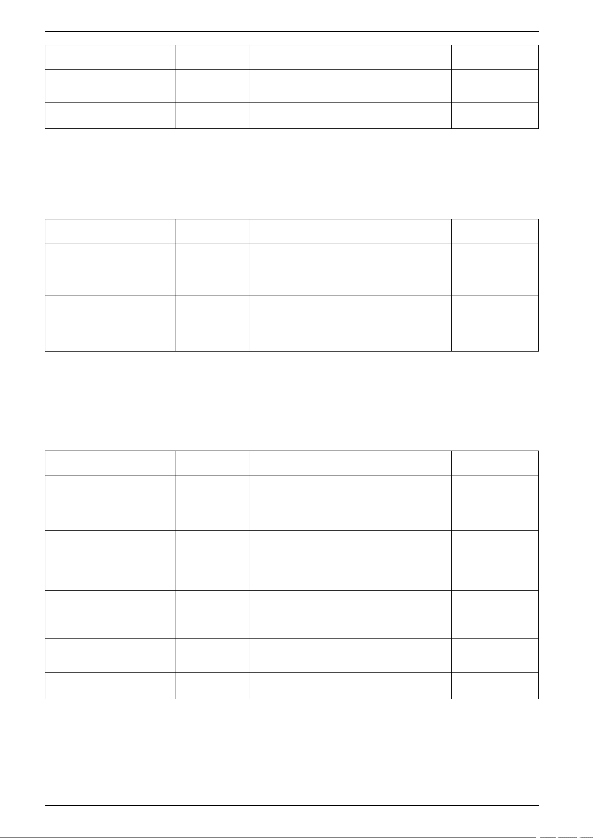
Predefined Events
The following events are generated when a Digital Module is installed or
uninstalled:
Code Event History Severity
0x1130 (4400) Digital module License installed Configuration Low
0x1131 (4401) Digital module License
uninstalled
Configuration Low
DOCA0102EN-07 37
Page 38

MasterPact MTZ - MicroLogic X Control Unit MicroLogic X Control Unit: Date and Time
MicroLogic X Control Unit: Date and Time
Presentation
MicroLogic X date and time are used for time stamping events to provide a
chronological order.
The date and time of the MicroLogic X control unit and the other ULP modules
(IFE, EIFE or IFM interface, IO module) of the intelligent modular unit (IMU) are
synchronized. Setting the date and time of one module sets the date and time of
all the modules of the IMU.
NOTE: The date and time of MicroLogic X and other ULP modules are
automatically reset to default value for the date (Jan 01 2000) when the
internal battery of the MicroLogic X control unit is removed and the control unit
has no other power supply.
Setting the Date and Time Manually
MicroLogic X date and time can be set manually:
• On MicroLogic X display screen, at Home > Configuration > General > Date
& Time. The first component of the date is day (dd) and the second
component is month (mm).
• With EcoStruxure Power Commission software:
◦ By manual setting
◦ By user-initiated synchronization with date and time of the PC running
EcoStruxure Power Commission software
• With EcoStruxure Power Device app:
◦ By manual setting
◦ By user-initiated synchronization with date and time of the smartphone
running the application
• With a web browser connected to the IFE or EIFE webpage.
• By sending a setting command using the communication network (passwordprotected).
Synchronizing the Date and Time
MicroLogic X date and time can be automatically updated:
• With the IFE or EIFE Ethernet interface with the following conditions:
◦ Ethernet interface is configured in SNTP mode
◦ Ethernet interface receives an update date and time request from the
SNTP server
NOTE: If the MicroLogic X control unit is connected to an Ethernet
interface configured in SNTP mode, manual update of the MicroLogic X
date and time is possible but is immediately replaced by the date and time
of the Ethernet interface.
• With the IFM Modbus-SL interface receiving an update date and time request
from the SNTP server
38 DOCA0102EN-07
Page 39

MicroLogic X Control Unit: Date and Time MasterPact MTZ - MicroLogic X Control Unit
Predefined Events
The following event is generated when date and time are set manually:
Code Event History Severity
0x1107 (4359) Date and time set Configuration Low
Recommended Actions
Code Event Recommended actions
0x1107 (4359) Date and time set Check the date and time displayed on the control
unit display screen.
DOCA0102EN-07 39
Page 40

MasterPact MTZ - MicroLogic X Control Unit MicroLogic X Control Unit: Power Supply
MicroLogic X Control Unit: Power Supply
Internal and External Power Supplies
The MicroLogic X control unit is powered by the current through the internal
current transformers (CT).
• The standard protection functions of MicroLogic X control units operate with
the internal current supply.
NOTE: The earth-leakage protection is powered by the system voltage
through the VPS voltage power supply module, installed as standard on
MicroLogic 7.0 X.
• If the load current is higher than 20% of the rated current In, the internal
current supply provides the power supply for the full functioning of the
MicroLogic X control unit. This includes:
◦ The MicroLogic X HMI, display screen and LEDs
◦ The metering functions with accuracies in accordance with IEC 61557-12
◦ The maintenance and diagnostic functions
◦ Communication through ULP modules
◦ Communication through Bluetooth Low Energy wireless technology
To provide a power supply to the MicroLogic X control unit when the load is below
20% of the rated current In, and maintain the full functioning of the MicroLogic X
control unit, optional power supplies can be used. Optional power supplies include
the following:
• Permanent power supplies:
◦ Internal voltage power supply (VPS) module, up to 600 Vac.
◦ External 24 Vdc power supply.
• Temporary power supplies connected to the mini USB port of the
MicroLogic X control unit:
◦ External Mobile Power Pack through USB connection.
◦ Android smartphone through USB OTG connection (smartphone should
be compatible with USB OTG - see list of compatible smartphones
available on the Schneider Electric website).
◦ PC through USB connection.
Each optional MicroLogic X power supply is described further.
40 DOCA0102EN-07
Page 41

MicroLogic X Control Unit: Power Supply MasterPact MTZ - MicroLogic X Control Unit
VPS Voltage Power Supply Module
DANGER
HAZARD OF ELECTRIC SHOCK, EXPLOSION OR ARC FLASH
• Do not install a VPS module on a network with a voltage above 600 Vac.
• Turn off all power supplies upstream and downstream of this equipment
before installation and removal.
Failure to follow these instructions will result in death or serious injury.
CAUTION
DETERIORATION OF VPS MODULE
Disconnect the VPS module by pulling it out to the disconnected position before
running a dielectric test on the equipment.
Failure to follow these instructions can result in injury or equipment
damage.
The VPS module is optional for MicroLogic 2.0 X, 3.0 X, 5.0 X, and 6.0 X. It is
installed as standard on MicroLogic 7.0 X.
The VPS module is installed in the lower part of
the MicroLogic X control unit and can be
replaced.
A green LED on the front face indicates that the
VPS module is powered and a 24 Vdc output is
supplied.
For information about spare part replacement
and installation, consult the instruction sheet on
the Schneider Electric website: NVE40741
The input voltage of the VPS module is limited
to 600 Vac. The module is directly connected to
the internal pickup voltage (PTI) on the
downstream side of the circuit breaker.
The VPS module can be supplied from an
external voltage by means of the optional PTE
voltage measurement inputs and voltage
transformers (mandatory for voltages above
600 Vac).
The external voltage can be picked up either
from the top or the bottom side of the circuit
breaker.
When the power source and the PTE option
are connected on the same side of the circuit
breaker (for example, power source and PTE
connected on top side), the MicroLogic X
control unit is energized as soon as the power
source is live, whatever the position of the
circuit breaker (open or closed).
When the power source and the PTE option
are connected on different sides of the circuit
breaker (for example, power source connected
on top side and PTE on bottom side), the
MicroLogic X control unit is energized only
when the circuit breaker is closed.
DOCA0102EN-07 41
Page 42

MasterPact MTZ - MicroLogic X Control Unit MicroLogic X Control Unit: Power Supply
External 24 Vdc Power Supply
The 24 Vdc power supply maintains the operation of all functions of the
MicroLogic X control unit in all circumstances, even when the circuit breaker is
open and not energized.
The 24 Vdc power supply maintains the functions of the MicroLogic X control unit
in low load conditions (load below 20%).
NOTICE
LOSS OF DOUBLE INSULATION
• Supply the MicroLogic X control unit with a 24 Vdc SELV (Safety Extra Low
Voltage) power supply only, connected through the ULP port module or
through the terminal block for external power supply (F1- F2+). Pay attention
to the polarity.
• Do not connect devices which do not have double insulation to the 24 Vdc
SELV power supply which is being used to supply the MicroLogic X control
unit. For example, do not use the same 24 Vdc SELV power supply to supply
a MicroLogic X control unit for MasterPact MTZ circuit breakers and a
MicroLogic A/E/P/H trip unit for MasterPact NT/NW circuit breakers.
Failure to follow these instructions will result in a basic/single insulated
system.
The design of MasterPact MTZ devices with MicroLogic X control units provides
double insulation at the front face and for circuit communication lines exiting the
device. Double or reinforced insulation is one of the protective measures against
electric shock which conforms to IEC and CENELEC HD 60364-4-41 (Low voltage
installations - Protection against electric shock).
NOTICE
HAZARD OF EQUIPMENT DAMAGE
Use the same 24 Vdc SELV power supply to supply the MicroLogic X control
unit and the other ULP modules connected to the ULP port module.
Failure to follow these instructions can result in equipment damage.
Recommendations for use of external 24 Vdc SELV power supplies:
• The same 24 Vdc SELV power supply can be used to supply several
MicroLogic X control units, depending on the overall power requirements of
the system.
• Use a separate 24 Vdc power supply to supply the MN/MX/XF voltage
releases or the MCH gear motor.
• Use the same 24 Vdc power supply to supply power to the MicroLogic X
control unit and the ULP modules.
• The 24 Vdc power supply can be used to supply power to the ESM ERMS
switch module.
42 DOCA0102EN-07
Page 43

MicroLogic X Control Unit: Power Supply MasterPact MTZ - MicroLogic X Control Unit
Recommended 24 Vdc Power Supplies
Available 24 Vdc power supplies include the range of Phaseo ABL8 power
supplies and the AD power supplies. For more information, refer to the MasterPact
MTZ Catalogue.
Characteristic Phaseo ABL8 power supply AD power supply
Illustration
Overvoltage
category defined by
IEC 60947-1
Input supply voltage
AC
Input supply voltage
DC
Dielectric withstand • Input/output: 4 kV RMS for
Temperature • 50 °C (122 °F)
Output current 3 A, 5 A, or 10 A 1 A
Ripple 200 mV peak-peak 200 mV peak-peak
Output voltage
setting for line loss
compensation
Category II • Category IV per IEC 62477-1 (Vac
• 110–120 Vac
• 200–500 Vac
–
1 minute
• Input/ground: 3 kV RMS
for 1 minute
• Output/ground: 0.5 kV
RMS for 1 minute
• 60 °C (140 °F) with 80%
nominal load maximum
24–28.8 Vdc 22.8–25.2 Vdc
model)
• Category III per IEC 62477-1 (Vdc
model)
• Category III per UL 61010-1
• 110–130 Vac
• 200–240 Vac
• 24–30 Vdc
• 48–60 Vdc
• 100–125 Vdc
Input/output:
• 3 kV RMS for 1 minute (110–130
Vac and 200–240 Vac model)
• 3 kV RMS for 1 minute (110–125
Vdc model)
• 2 kV RMS for 1 minute (24–30 Vdc
and 48–60 Vdc model)
70 °C (158 °F)
NOTE: For applications requiring an overvoltage category higher than II,
install a surge arrester when using a 24 Vdc ABL8 power supply.
24 Vdc Backup Battery
If the 24 Vdc power supply is interrupted, a 24 Vdc backup battery can be used to
maintain the operation of the MicroLogic X control unit, including wireless
communication. It is installed in series between the MicroLogic X control unit and
the 24 Vdc power supply module.
The 24 Vdc backup battery must have the following characteristics (compatible
with the MicroLogic X control unit):
• Output voltage 17 V–28.8 Vdc
◦ Cut-off voltage 17 Vdc (24 Vdc backup battery must have a shutdown
output voltage in case of low voltage level)
DOCA0102EN-07 43
Page 44

MasterPact MTZ - MicroLogic X Control Unit MicroLogic X Control Unit: Power Supply
◦ Hysteresis > 3 Vdc (to avoid power-on before the voltage is up to 21 Vdc)
• 24 Vdc backup battery should be able to power an Inrush current of 10 A
NOTE: Refer to the table of power consumption to calculate the necessary
battery capacity for your installation.
Mobile Power Pack
The Mobile Power Pack is an external battery that enables
power to be supplied temporarily to the MicroLogic X control
unit.
The Mobile Power Pack enables use of the MicroLogic X display
screen and keypad for setting and displaying when the power
supply to the MicroLogic X control unit is interrupted.
The external Mobile Power Pack can be connected by using a
USB cable connected to the mini USB port on the MicroLogic X
control unit.
Check the charge level of the Mobile Power Pack by pressing the test button for
one second. The indicator on the Mobile Power Pack lights up to indicate the
remaining charge.
NOTE: During periods of setting, commissioning, testing, and maintenance, a
smartphone (with USB OTG connection) or a PC connected through mini USB
port also provide a temporary power supply.
Internal Battery
When no other power supply is supplying the MicroLogic X control unit, the
internal battery powers:
• The trip cause LEDs
• The service LED
• The internal clock (date and time)
• The maintenance schedule function
ULP Module Consumption
The following table lists the ULP module consumption:
Module Typical
MicroLogic X control unit
for MasterPact MTZ circuit
breaker
with external 24 Vdc
power supply
supplied through
mini USB port
supplied through
ULP port module
consumption
(24 Vdc at
20 °C/68 °F)
200 mA 300 mA
400 mA 500 mA
200 mA 335 mA
Maximum
consumption
(19.2 Vdc at
60 °C/140 °F)
M2C programmable contacts 25 mA 45 mA
ESM ERMS switch module 25 mA 45 mA
IFE Ethernet interface for one circuit breaker 100 mA 140 mA
IFE Ethernet switchboard server 100 mA 140 mA
EIFE embedded Ethernet interface for one
MasterPact MTZ drawout circuit breaker
IFM Modbus-SL interface or one circuit breaker 21 mA 30 mA
44 DOCA0102EN-07
115 mA 180 mA
Page 45

MicroLogic X Control Unit: Power Supply MasterPact MTZ - MicroLogic X Control Unit
Module Typical
IO input/output application module for one circuit
breaker
ULP port module for MasterPact MTZ circuit
breaker
consumption
(24 Vdc at
20 °C/68 °F)
100 mA 130 mA
0 mA 0 mA
Maximum
consumption
(19.2 Vdc at
60 °C/140 °F)
DOCA0102EN-07 45
Page 46

MasterPact MTZ - MicroLogic X Control Unit MicroLogic X Control Unit: Firmware Update
MicroLogic X Control Unit: Firmware Update
Introduction
The primary reason for updating the firmware of a MicroLogic X control unit is to
obtain the latest MicroLogic features. If the latest MicroLogic features are not
required, it is not mandatory to update the firmware of the MicroLogic X control
unit and the Enerlin’X devices of the IMU.
You may need to perform firmware updates to enable compatibility between
MicroLogic X control units and Digital Modules installed on the control unit, page
29.
The standard protection functions of the MicroLogic X control unit remain active
during a firmware update.
Use the latest version of EcoStruxure Power Commission software, page 22 for all
firmware updates.
For more information about firmware updates refer to the following documents:
• DOCA0144EN MasterPact MTZ - MicroLogic X Control Unit - Firmware
Release Note
• DOCA0155EN MicroLogic Trip Units and Control Units - Firmware History
After updating the firmware version of the MicroLogic X control unit, use the latest
version of EcoStruxure Power Commission software to check the firmware
compatibility between the IMU devices. The Firmware Update table helps you to
diagnose and identify all discrepancy issues between the IMU devices. This table
also provides the recommended actions relevant to the detected discrepancies.
Checking the Firmware Version
Check the firmware version:
• On the MicroLogic X display screen at Home > Maintenance > Assistance >
Firmware version
• With EcoStruxure Power Commission software
• With EcoStruxure Power Device app
Updating Firmware With EcoStruxure Power Commission
Software
NOTICE
INTERRUPTION OF POWER SUPPLY
The MicroLogic X control unit must be continuously powered during the
firmware update.
Failure to follow these instructions will result in deterioration of the
control unit.
The prerequisites for updating the firmware with EcoStruxure Power Commission
software are the following:
• The latest version of EcoStruxure Power Commission software must be
downloaded and installed on the PC.
• The PC must be connected to a power supply. Standby mode must be
deactivated to avoid the possibility of interruption during the update.
• The PC must be connected to the mini USB port on the MicroLogic X control
unit.
46 DOCA0102EN-07
Page 47

MicroLogic X Control Unit: Firmware Update MasterPact MTZ - MicroLogic X Control Unit
• The MicroLogic X control unit must be powered.
◦ When the control unit is not connected to other ULP modules, it is
powered by the PC through the mini USB port.
◦ When the control unit is connected to other ULP modules, it must be
powered by an external 24 Vdc power supply
The Administrator password of the MicroLogic X control unit is required to launch
the firmware update.
For more information, refer to EcoStruxure Power Commission Online Help.
EcoStruxure Power Commission software is available at www.se.com
NOTE: For MicroLogic X control units with firmware version greater than or
equal to 002.000.000, the update of the firmware of the associated Enerlin’X
devices is also possible with EcoStruxure Power Commission software while
the PC is connected to the mini USB port of the MicroLogic X control unit.
Predefined Events
The following events can be generated when a firmware update is performed:
Code Event History Severity
0x0D01 (3329) Critical firmware modules discrepancy Diagnostic Medium
0x0D03 (3331) Non-critical firmware modules discrepancy Diagnostic Medium
0x0D09 (3337) Firmware discrepancy within control unit Diagnostic Medium
0x1434 (5172) Self diagnostic test - firmware Diagnostic Medium
0x112B (4395) Control unit firmware upgrade mode Configuration Low
0x112C (4396) Control unit firmware upgrade
Recommended Actions
Code Event Recommended actions
0x0D01 (3329) Critical firmware modules
0x0D03 (3331) Non-critical firmware modules
0x0D09 (3337) Firmware discrepancy within
unsuccessful
discrepancy
discrepancy
control unit
Configuration Medium
Check which module is in critical
firmware discrepancy with the
EcoStruxure Power Commission
software. Update the module.
Check which module is in non-critical
firmware discrepancy with the
EcoStruxure Power Commission
software. Plan to update the module.
Check the firmware version of the
MicroLogic X control unit with
EcoStruxure Power Commission
software. If not latest, update the
firmware of the MicroLogic X control unit.
0x1434 (5172) Self diagnostic test - firmware Update the firmware of the MicroLogic X
0x112B (4395) Control unit firmware upgrade
mode
0x112C (4396) Control unit firmware upgrade
unsuccessful
control unit with EcoStruxure Power
Commission software.
Wait until the update of the MicroLogic X
control unit firmware is completed.
Restart the MicroLogic X control unit
firmware update procedure. If the
message is displayed again, plan to
replace the MicroLogic X control unit.
Contact your field service representative for more information about who can carry
out the recommended actions.
DOCA0102EN-07 47
Page 48

MasterPact MTZ - MicroLogic X Control Unit
Using the MicroLogic X Human Machine Interface
What’s in This Part
MicroLogic X HMI Description ......................................................................... 49
HMI Display Modes ........................................................................................52
Quick View Mode ...........................................................................................53
Tree Navigation Mode .................................................................................... 57
Protection Setting Procedure........................................................................... 64
Measures Menu ............................................................................................. 67
Alarms & History Menu ...................................................................................72
Maintenance Menu......................................................................................... 74
Configuration Menu........................................................................................76
Protection Menu.............................................................................................79
Pop-up Event Messages.................................................................................85
48 DOCA0102EN-07
Page 49

MicroLogic X HMI Description MasterPact MTZ - MicroLogic X Control Unit
MicroLogic X HMI Description
Introduction
The human machine interface (HMI) of the MicroLogic X control unit includes:
• A graphic display screen with colored backlight
• Buttons to navigate through the menu structure, and access monitored
parameters and configuration settings
Display Screen and Buttons
The MicroLogic X control unit includes the following display screen with contextual
and dedicated buttons:
A Screen name
B Functional screen content
C Scroll bar indicating the relative position of
the items in a list larger than the display screen
D Context-specific function icons
E Contextual buttons that perform the context-
specific function described by the icon
immediately above each button
F Escape button, used to return to the previous
screen and/or trigger a data saving confirmation
screen
G Home button, used to jump to the Home
screen and/or trigger a data saving confirmation
screen
Button Functional Types
Use the buttons beneath the display screen to:
• Navigate the menu structure
• Display monitored values
• Access and edit configuration settings
The control unit provides the following types of buttons:
• Contextual buttons: each screen can have up to three contextual buttons. The
function of each button is determined by an icon located on the display screen
directly above it.
• Dedicated buttons that perform the escape and home functions.
DOCA0102EN-07 49
Page 50

MasterPact MTZ - MicroLogic X Control Unit MicroLogic X HMI Description
Contextual Buttons
Icon displayed Description
Use the up and down buttons to move between:
• Screen names within the same level of menu hierarchy
• List items
The up and down arrows do not support looping back. At a terminus of a menu
structure or item list, either the up or down arrow is no longer displayed
(depending on whether the terminus is the beginning or end of the list). The up
and down navigation behavior is the same for all menus and lists.
OK Use the OK button:
• To validate a selection
• To navigate from the level currently displayed in the hierarchy to the
selected sublevel immediately below it. In this way, navigation is possible
from:
◦ The active menu to the immediate submenu
◦ A submenu to a monitored item or configuration parameter
◦ A monitored item to its monitored value
◦ A configuration parameter to its configuration setting
• To view details and acknowledge an event pop-up screen or error message
Dedicated Buttons
Y
N
+
–
Icon displayed Description
ESC Use the ESC (escape) button to:
Use the Y (Yes) and N (No) buttons to acknowledge actions, for example, when a
confirmation screen is displayed.
Use the + and – buttons to increment or decrement a configuration setting, either
numerical values or predefined list items.
• Navigate from the level currently displayed in the hierarchy to the level
immediately above
• Save a change to a configuration setting. A confirmation screen pops up
and must be acknowledged before returning to the menu on the level
above.
Use the home button to:
• Return to the Home screen
• Save a change to a configuration setting. A confirmation screen pops up
and must be acknowledged before returning to the Home screen.
50 DOCA0102EN-07
Page 51

MicroLogic X HMI Description MasterPact MTZ - MicroLogic X Control Unit
Display Screen Backlight
The backlight color and intensity depends on the operating state of the control
unit, as follows:
Backlight color Control unit operating state
(1)
White
Red A trip or a high severity event message is displayed.
• Quick View scrolling is enabled and running
• Tree navigation mode is enabled for navigating among menus in
display screens
• Bluetooth Low Energy wireless communication is enabled and the
Bluetooth pairing message is displayed.
Orange A medium severity event message is displayed, and no trip or high severity
Blue ERMS engaged.
(1) The backlight of the Health screen in Quick View and in Maintenance is:
• Red if a high severity event is active.
• Orange if a medium severity event is active.
NOTE: When Quick View scrolling is off, the backlight changes from high
intensity to low intensity when in standby. High intensity resumes when a
button is pressed.
Display Screen Language
To change the display screen language, go to:
Home > Configuration > General > Language
Selections include:
• Deutsch
• English (US)
• Español
• Français
• Italiano
•
•
• English (UK)
• Português
The default language is as follows:
• IEC standard MicroLogic X control unit: English (UK)
• UL standard MicroLogic X control unit: English (US)
event is active.
Start-up Screen
The start-up screen is displayed every time the MicroLogic X control unit is
energized. None of the buttons on the control unit are functional while this
screen is displayed. The screen is displayed for the period of the control unit
start-up time. At the end of this period, the Home screen or any active pop-up
screen is displayed.
NOTE: Standard protection functions are operational during start-up
screen.
DOCA0102EN-07 51
Page 52

MasterPact MTZ - MicroLogic X Control Unit HMI Display Modes
HMI Display Modes
Presentation
The MicroLogic X control unit HMI supports the following display modes:
• Quick View mode to display a selection of data
• Tree Navigation mode to access all data through a menu structure
NOTE: Both Quick View and Tree Navigation display modes are overridden by
event messages, page 86.
Quick View Mode
Quick View is the default HMI display mode. It displays a selection of data
screens.
When Quick View scrolling is enabled, the screens are displayed automatically
one after the other with a configurable time delay.
When Quick View scrolling is disabled, the Quick View screens are available at
Home > Quick View.
Tree Navigation Mode
In Tree Navigation display mode, use the contextual buttons to navigate in the
menu structure. Tree Navigation display mode presents a single network of
menus, with monitoring values and editable configuration settings.
Tree navigation is always accessible from Quick View screens by pressing the
home button.
Refer to the MicroLogic X local HMI description, page 50 for information about
how to use the HMI buttons to:
• Navigate the menu structure
• Access and edit settings
52 DOCA0102EN-07
Page 53

Quick View Mode MasterPact MTZ - MicroLogic X Control Unit
Quick View Mode
Quick View
Quick view presents a sequence of screens, depending on the type of
MicroLogic X control unit. Each screen displays a snapshot of operating values for
the control unit. The values shown on the protection screens are the active
protection settings currently used by the protection functions.
With automatic scrolling enabled, the screens are displayed in sequence with a
configurable time delay. With automatic scrolling disabled, the screens can be
navigated manually.
Quick View scrolling is enabled as the factory setting.
When the MicroLogic X control unit is switched on, Quick View scrolling begins
after the configured timeout if there are no active event messages.
Configure the Quick View display by setting:
• The display time for each screen in the Quick View scrolling sequence.
• The time delay for automatically resuming scrolling after scrolling has been
interrupted.
If scrolling is off, the Quick View Current screen is displayed after this time
delay.
The following is an example of the Quick View screens for the MicroLogic 6.0 X
control unit.
DOCA0102EN-07 53
Page 54

MasterPact MTZ - MicroLogic X Control Unit Quick View Mode
List of Quick View Screens
Depending on the type of the MicroLogic X control unit, Quick View displays the
following screens:
Screen Description MicroLogic X type
(1)
Health
Displays the health state of the circuit breaker:
•
OK (white)
MicroLogic 2.0 X,
3.0 X, 5.0 X, 6.0 X,
7.0 X
•
•
Start-up screen Reminds the user to download the EcoStruxure Power Device app mobile application to
(1)
Current
Network
Power
Energy
Trip curve • When in fallback settings mode, displays message Fallback settings mode.
LI settings Displays a selection of active protection settings:
LI settings Displays a selection of active protection settings:
LSI settings Displays a selection of active protection settings:
I
I earth leakage Displays a selection of active protection settings:
(1) Screen data is refreshed every second.
(1)
(1)
(1)
manage the MicroLogic X control unit.
Displays I1, I2, I3 RMS current on phase 1, 2, 3 values as bar graphs expressed in % of Ir.
The highest phase current value is displayed in Amps under the bar graph.
Displays real-time values for:
• Average of 3 RMS phase-to-phase voltage
• Frequency
• Power factor
Displays real-time values for:
• P tot: total active power
• Q tot: total reactive power
• S tot: total apparent power
Displays real-time values for:
• Ep: total active energy
• Eq: total reactive energy
• Es: total apparent energy
• When ERMS is engaged, displays message ERMS engaged
• When ERMS is disengaged and dual setting is on, displays:
• When ERMS is disengaged and dual setting is off, no screen is displayed
• Long time overcurrent protection threshold Ir
• Long time overcurrent protection time delay tr
• Instantaneous overcurrent protection threshold Isd
• Long time overcurrent protection threshold Ir
• Long time overcurrent protection time delay tr
• Instantaneous overcurrent protection threshold Ii
• Long time overcurrent protection threshold Ir
• Long time overcurrent protection time delay tr
• Short time overcurrent protection threshold Isd
• Short time overcurrent protection time delay tsd
• Instantaneous overcurrent protection threshold Ii
Displays a selection of active protection settings:
• Ground fault protection threshold Ig
• Ground fault protection time delay tg
• Earth-leakage protection threshold IΔn
• Earth-leakage protection time delay Δt
Medium - severity detected alarm that requires non - urgent action (orange)
High - severity detected alarm that requires immediate action (red)
◦ Dual set ON A curve activated or
◦ Dual set ON B curve activated
MicroLogic 2.0 X,
3.0 X, 5.0 X, 6.0 X,
7.0 X
MicroLogic 2.0 X,
3.0 X, 5.0 X, 6.0 X,
7.0 X
MicroLogic 2.0 X,
3.0 X, 5.0 X, 6.0 X,
7.0 X
MicroLogic 2.0 X,
3.0 X, 5.0 X, 6.0 X,
7.0 X
MicroLogic 2.0 X,
3.0 X, 5.0 X, 6.0 X,
7.0 X
MicroLogic 2.0 X,
3.0 X, 5.0 X, 6.0 X,
7.0 X
MicroLogic 2.0 X
MicroLogic 3.0 X
MicroLogic 5.0 X,
6.0 X, 7.0 X
MicroLogic 6.0 X
MicroLogic 7.0 X
54 DOCA0102EN-07
Page 55

Quick View Mode MasterPact MTZ - MicroLogic X Control Unit
NOTE: The value of the settings displayed on the Quick View screens are the
active settings used by the protection functions. They may differ from the
settings displayed in the Protection menu when Fallback settings mode,
page 123 is displayed on the Trip curve screen.
Configuring Quick View Mode
To configure Quick View settings, go to Home > Configuration > General >
Quick view. The following settings are available:
• Scrolling: Set this to ON to enable automatic scrolling in Quick View. (When
OFF is selected, the Quick View Current screen is displayed after the
configured timeout.)
When Quick View scrolling is enabled, the following settings are available:
• Pageflow: The length of time each Quick View screen is displayed while
scrolling.
• Auto start: The time delay before Quick View scrolling resumes after an
interruption. This time delay is also the event timeout, which is the time delay
before an event message is displayed again if the event cause is not
acknowledged by pressing OK.
When Quick View scrolling is disabled, the following setting is available:
Time out: The time delay before the Quick View Current screen is displayed. This
time delay is also the event timeout, which is the time delay before an event
message is displayed again if the event cause is not acknowledged by pressing
OK.
The configurable settings are shown in the following table.
Setting Unit Range Step Factory Setting
Scrolling
Pageflow seconds 3–60 1 3
Auto start minutes 1–60 1 15
Time out minutes 1–60 1 15
Starting Quick View Scrolling
When Quick View scrolling is enabled, the scrolling can be restarted:
• Automatically
• Manually
To begin Quick View scrolling automatically, wait for the Auto start timeout to
elapse.
–
ON/OFF
–
ON
To begin Quick View scrolling manually:
Step Action
1 In the Home menu, select Quick view.
2 Press OK to restart scrolling of the Quick View screens.
DOCA0102EN-07 55
Page 56

MasterPact MTZ - MicroLogic X Control Unit Quick View Mode
Stopping Quick View Scrolling
Stop Quick View scrolling as follows:
• Press the ESC or home button. The display screen displays the Home menu.
From here, use the up and down buttons to navigate through the menu
structure.
NOTE: If no button is pressed before the Auto start timeout expires,
Quick View scrolling resumes.
• Press one of the three contextual buttons. Quick View scrolling stops. Use the
up and down buttons to scroll manually through the Quick View screens.
When the MicroLogic X control unit detects any of the following events, Quick
View scrolling is interrupted and a pop-up message is displayed, page 85:
• Bluetooth pairing
• Trip
• High severity alarm
• Medium severity alarm
• ERMS engaged
Disabling Quick View Automatic Scrolling
To disable Quick View scrolling:
Step Action
1 Press the home button.
2
Go to Home
3 Press OK.
4 Use the + or - contextual buttons to set the Scrolling setting to:
• ON to select Quick View automatic scrolling.
• OFF to disable Quick View automatic scrolling.
5
Press OK to save the selection.
6 Press ESC or the home button.
A confirmation screen is displayed.
7
In the confirmation screen press one of the following:
• Y to confirm the change of settings.
• N to undo the edit.
> Configuration > General > Quick view.
56 DOCA0102EN-07
Page 57

Tree Navigation Mode MasterPact MTZ - MicroLogic X Control Unit
Tree Navigation Mode
Tree Structure Screen Display
Use Tree Navigation mode to navigate manually through the MicroLogic X control
unit menu structure. Tree Navigation mode enables the following actions:
• Display measurement values for the control unit
• View active alarms, and event history
• View maintenance items, and a history of service records
• Display and edit control unit configuration settings
• Display and edit protection settings
All Tree Navigation menu selections begin at the home button:
Click the link on one of the following level 2 menus to see its content:
Level 1 Level 2
Home Quick View, page 53
Measures, page 67
Alarms & history, page 72
Maintenance, page 74
Configuration, page 76
Protection, page 79
Navigating in the Menu Structure
Use the contextual and dedicated buttons on the face of the MicroLogic X control
unit to navigate in the menu structure, and to access displayed values and
configurable settings.
The possible operations are listed below, and are illustrated with an example:
• Display data, for example, energy values
• Reset values or counters, for example, reset the maximum RMS current
• Select options in a list, for example, language
• Edit a value, for example, nominal voltage
• Set protection settings, for example, long-time overcurrent protection
DOCA0102EN-07 57
Page 58

MasterPact MTZ - MicroLogic X Control Unit Tree Navigation Mode
• Validate a pop-up message, for example, a pop-up trip message
Displaying Data
The following example shows how to display energy values:
Step Action Screen
1 Press the home button. The Home menu opens.
Press the down arrow to select Measures.
2 Press OK. The Measures menu opens.
Press the down arrow to select Energy.
3 Press OK. The Energy menu opens.
Press the down arrow to select E received.
4 Press OK. The E received screen is displayed.
5
To exit the E received screen, press one of the following:
• The ESC button to return to the Energy menu.
• The home button to return to the Home menu.
58 DOCA0102EN-07
Page 59

Tree Navigation Mode MasterPact MTZ - MicroLogic X Control Unit
Resetting Values
Some menus present values or counters that can be reset. The following example
shows how to navigate to and reset the maximum RMS current:
Step Action Screen
1 Press the home button. The Home menu opens.
Press the down arrow to select Measures.
2 Press OK. The Measures menu opens.
Select Current.
3 Press OK. The Current menu opens.
Press the down arrow to select Reset Max.
4 Press OK. The Reset Max confirmation screen opens.
5
In the confirmation screen, press one of the following:
• Y to reset the maximum RMS current and return to the Current
screen.
• N to return to the Current screen without resetting the value.
–
DOCA0102EN-07 59
Page 60

MasterPact MTZ - MicroLogic X Control Unit Tree Navigation Mode
Selecting Options in a List
Some menus present options in a list. The following example shows how to
navigate to and select language options:
Step Action Screen
1 Press the home button. The Home menu opens.
Press the down arrow to select Configuration.
2 Press OK. The Configuration menu opens.
Select General.
3 Press OK. The General menu opens.
Select Language.
4 Press OK. The Language menu opens.
5 Press the up and down arrow buttons to select a language and press
OK.
A confirmation check appears next to the selected language.
6 To save the selection, press one of the following:
• The ESC button to return to the General menu.
• The home button to return to the Home menu.
7
In the confirmation screen press one of the following:
• Y to confirm the change of settings.
• N to undo the edit.
–
60 DOCA0102EN-07
Page 61

Tree Navigation Mode MasterPact MTZ - MicroLogic X Control Unit
Restoring the Language Settings
If the language selected for the display screen is unfamiliar to you, the following
example shows how the language settings can be restored to a familiar language:
Step Action Screen
1 Press the home button. The Home menu opens.
Press the down arrow three times to reach the third line in the menu. This
is the Configuration menu.
2 Press OK. The Configuration menu opens.
Select the first line.This is the General menu.
3 Press OK. The General menu opens.
Select the first line.This is the Language menu.
4 Press OK. The Language menu opens.
Press the up and down arrow buttons to select the language you want to
change to and press OK.
5
To save the selection, press one of the following:
• The ESC button to return to the General menu.
• The home button to return to the Home menu.
6 In the confirmation screen press one of the following:
• Y to confirm the change of settings.
• N to undo the edit.
DOCA0102EN-07 61
Page 62

MasterPact MTZ - MicroLogic X Control Unit Tree Navigation Mode
Editing and Saving Parameter Settings
When editing a parameter setting, use the + or – buttons to increment or
decrement the setting by a single-step amount. Hold down the button to
accelerate the process.
This function applies to both numeric values and list selections.
The following example shows how to edit the nominal voltage:
Step Action Screen
1 Press the home button. The Home menu opens.
Press the down arrow to select Configuration.
2 Press OK. The Configuration menu opens.
Press the down arrow to select Network.
3 Press OK. The Network menu opens.
Select Nominal voltage.
4 Press OK. The Nominal voltage menu opens.
5
In the Nominal voltage menu, select Vn (V) and press OK to enable
editing of the Vn (V) parameter.
The parameter is displayed in black on a white background to indicate
that editing is enabled.
In this example, 400, the factory setting value, is displayed.
6 Press the + and – buttons to scroll through available settings.
Possible values are 208, 220, 230, 240, 380, 400, 415, 440, 480, 500,
525, 550, 575, 600, 660, 690, and 1,000.
Press OK to select a setting.
The background changes to black.
7
To save the change of settings, press one of the following:
• The ESC button to return to the Nominal voltage screen
• The home button to return to the Home menu
8 In the confirmation screen, press one of the following:
• Y to confirm and save the change of settings.
• N to undo the edit.
–
If the edit did not succeed, a detected error message appears. Press OK to
confirm the message, and then the previous menu is displayed.
62 DOCA0102EN-07
Page 63

Tree Navigation Mode MasterPact MTZ - MicroLogic X Control Unit
Setting Protection Settings
The procedure for setting protection settings conforms to UL489SE. New settings
are submitted and applied in separate steps, page 64.
Validating a Pop-Up Message
A trip or alarm event displays a pop-up message on the display screen. The
message overrides the screen currently displayed.
The following example shows how to handle a pop-up trip message.
Step Action Screen
1 A pop-up trip message appears on the screen.
2 Press OK to view details of the trip.
3 If a down arrow appears at the bottom of the screen, press the down
arrow to view more details about the trip event.
4 After taking steps to resolve the cause of the trip, press OK to
acknowledge the trip context. The Alarms & history screen is
displayed.
5
To exit the Alarms & history screen, press one of the following:
• The ESC button to return to the screen displayed before the pop-
up message appeared
• The home button to return to the Home menu
–
–
DOCA0102EN-07 63
Page 64

MasterPact MTZ - MicroLogic X Control Unit Protection Setting Procedure
Protection Setting Procedure
Protection Setting Session
The procedure for setting a protection setting conforms to UL489SE, with an
exclusive editing session and a two-step procedure for submitting and applying
protection setting changes.
To set a protection setting, access to protection settings must be enabled by using
the MicroLogic X HMI, page 96.
Setting Protection Settings
The following example shows how to set the long-time overcurrent protection:
Step Action Screen
1 Press the home button. The Home menu opens.
Press the down arrow to select Protection.
2 Press OK. The Protection menu opens.
Select I long time.
3 Press OK. The editing session opens and the I long time menu is
displayed.
In the I long time menu, select the Ir (x In) parameter.
4 Press OK to enable editing of the Ir (x In) parameter.
The parameter is displayed in black on a white background to indicate
that editing is enabled.
5 Press the + and – buttons to scroll through available settings.
Press OK to confirm the new setting.
The parameter is displayed in white on a black background.
6 Use the down arrow and OK to select the next parameter to be set and
repeat step 5.
7
To submit the new settings, press one of the following:
• The ESC button
• The home button
64 DOCA0102EN-07
–
–
Page 65

Protection Setting Procedure MasterPact MTZ - MicroLogic X Control Unit
Step Action Screen
8 In the submit settings screen, press one of the following:
• Y to submit the new settings.
• N to cancel the change of settings. The screen displays the
Home menu if the home button was pressed in the previous
step, or the Protection menu if ESC was pressed in the previous
step.
If you do not press Y to submit the new settings within five minutes of
opening the editing session, the changes are rejected and a pop-up
notice is displayed (see following table).
9 The screen displays the new settings. The values on the screen are
for display only. They cannot be edited. Press one of the following:
• ✔ to apply the change of settings.
• X to cancel the change of settings and return to the Protection
menu.
If you do not press ✔ to apply the new settings within five minutes, the
changes are rejected and a pop-up notice is displayed (see following
table).
NOTE: The ESC and home buttons are deactivated when this
screen is displayed. Pressing these buttons has no effect.
10 After applying the settings, the screen displays the new settings on an
editable screen.
Close the editing session by pressing one of the following:
• The ESC button, to return to the Protection menu
• The home button, to return to the Home page
Pop-up Notices
The following table indicates the necessary action to take if a pop-up notice is
displayed while editing a protection setting:
Message Description Action
Protection locked.To unlock
go to Configuration menu.
Access to protection settings is
disabled.
Press OK to acknowledge the
message and display the
Protection menu. The
protection parameters are
accessible for display only.
Go to Home
> Configuration
> General > Lock protection
on the MicroLogic X display
screen to enable access to
protection settings, page 96.
Access denied. Another
session already opened
You cannot open an editing
session to set protection
settings because a session is
open on another interface
(EcoStruxure Power
Commission software,
EcoStruxure Power Device
app, communication network),
page 97.
Press OK to acknowledge the
message and return to the
Protection menu. Protection
settings are for display only,
and can be consulted on the
Quick View screens. It is not
possible to set settings as long
as a session is open on
another interface. Try again
later.
DOCA0102EN-07 65
Page 66

MasterPact MTZ - MicroLogic X Control Unit Protection Setting Procedure
Message Description Action
Session expired No key pressed for five
Access denied due to sensor
plug missing. Check sensor
plug.
minutes. The editing session
expired on time-out, page 97.
The new settings are rejected
and the existing protection
settings are maintained.
The sensor plug is missing or
incorrectly connected.
Press OK to acknowledge the
message and return to the
Protection menu. Open a new
editing session by selecting a
protection function in the menu.
Press OK to acknowledge the
message and return to the
Home menu. It is not possible
to display or set protection
settings.
Contact your field service
representative to check, and
replace or reconnect the
sensor plug.
66 DOCA0102EN-07
Page 67

Measures Menu MasterPact MTZ - MicroLogic X Control Unit
Measures Menu
Presentation
In this guide, electrical phases are described as phase 1, phase 2, phase 3 and
cover both IEC standard and UL standard. The MicroLogic X control unit displays
the phases as follows:
MicroLogic X control unit for IEC standard MicroLogic X control unit for UL standard
Phase 1 Phase a
Phase 2 Phase b
Phase 3 Phase c
Description
The Measures menu contains the following submenus:
Level 1 Level 2 Level 3 Function description
Home Measures Current Current real-time measurements
Voltage Voltage real-time measurements
Power Power real-time measurements
Energy Energy real-time measurements
Frequency Frequency real-time measurements
I harmonics Current harmonics real-time measurements
V harmonics Voltage harmonics real-time measurements
Power factor Power factor real-time measurements
Measures Screens with Quality Gauge
A quality gauge is displayed on the following screens to give a graphical
representation of the measurement compared to the expected range:
• Real-time maximum of 3 phase current unbalances, Iunb
• Average of 3 RMS phase-to-phase voltages Vavg VLL(V)
• Real-time maximum of 3 phase-to-phase voltage unbalances Vunb VLL(%)
• Frequency F(Hz)
For example, for the frequency screen, the following icons indicate the
measurement compared to the expected range:
Measurement OK: the
difference between the
measured and expected
frequencies is less than 1%
DOCA0102EN-07 67
Measurement out of
range: the difference between
the measured and expected
frequencies is +1–4% or -1–
-6%
Measurement
significantly out of range: the
difference between the
measured and expected
frequencies is greater than
+4% or less than -6%
Page 68

MasterPact MTZ - MicroLogic X Control Unit Measures Menu
Current
The Current menu presents the following measurements:
Level 3 Level 4 Level 5 Parameter name
Current I I1 (A) RMS current on phase 1
I2 (A) RMS current on phase 2
I3 (A) RMS current on phase 3
(1)
IN (A)
(2)
Ig (A)
(3)
IΔn (A)
I MAX I1 (A) Maximum RMS current on phase 1
I2 (A) Maximum RMS current on phase 2
I3 (A) Maximum RMS current on phase 3
(1)
IN (A)
(2)
Ig (A)
(3)
IΔn (A)
RMS current on neutral
RMS current on ground
RMS current on earth leakage
Maximum RMS current on neutral
Maximum of RMS current on ground
Maximum of RMS current on earth leakage
Voltage
I avg I (1,2,3) (A) Average of 3 phase RMS currents
I unb I (1,2,3) (%) Real-time maximum of 3 phase current
unbalances, with quality gauge
I unb MAX I (1,2,3) (%) Maximum of maximum of 3 phase current
unbalances
Reset MAX Reset of maximum RMS current, with date and
time of last reset
(1) Applies to 4-pole circuit breakers or 3-pole circuit breakers with ENCT wired and configured
(2) Applies to MicroLogic 2.0 X, 3.0 X, 5.0 X, 6.0 X
(3) Applies to MicroLogic 7.0 X
The Voltage menu presents the following measurements:
Level 3 Level 4 Level 5 Parameter name
Voltage V V12 (V) RMS phase-to-phase voltage 1-2
V23 (V) RMS phase-to-phase voltage 2-3
V31 (V) RMS phase-to-phase voltage 3-1
(1)
V1N (V)
V2N (V)
V3N (V)
(1)
(1)
RMS phase-to-neutral voltage 1-N
RMS phase-to-neutral voltage 2-N
RMS phase-to-neutral voltage 3-N
V MAX V12 (V) Maximum RMS phase-to-phase voltage 1-2
V23 (V) Maximum RMS phase-to-phase voltage 2-3
V31 (V) Maximum RMS phase-to-phase voltage 3-1
(1)
V1N (V)
V2N (V)
V3N (V)
(1)
(1)
Maximum RMS phase-to-neutral voltage 1-N
Maximum RMS phase-to-neutral voltage 2-N
Maximum RMS phase-to-neutral voltage 3-N
V MIN V12 (V) Minimum RMS phase-to-phase voltage 1-2
68 DOCA0102EN-07
Page 69

Measures Menu MasterPact MTZ - MicroLogic X Control Unit
Level 3 Level 4 Level 5 Parameter name
V23 (V) Minimum RMS phase-to-phase voltage 2-3
V31 (V) Minimum RMS phase-to-phase voltage 3-1
(1)
V1N (V)
V2N (V)
V3N (V)
(1)
(1)
Minimum RMS phase-to-neutral voltage 1-N
Minimum RMS phase-to-neutral voltage 2-N
Minimum RMS phase-to-neutral voltage 3-N
Power
V avg VLL (V) Average of 3 RMS phase-to-phase voltages
(V12+V23+V31)/3, with quality gauge
VLN (V)
(1)
Average of 3 RMS phase-to-neutral voltages
(V1N+V2N+V3N)/3
V unb VLL (%) Real-time maximum of 3 phase-to-phase
voltage unbalances, with quality gauge
VLN (%)
(1)
Real-time maximum of 3 phase-to-neutral
voltage unbalances
V unb MAX VLL (%) Maximum of maximum of 3 phase-to-phase
voltage unbalances
VLN (%)
(1)
Maximum of maximum of 3 phase-to-neutral
voltage unbalances
Reset MIN/MAX Reset of minimum and maximum RMS
voltage, with date and time of last reset
(1) Applies to 4-pole circuit breakers or 3-pole circuit breakers with ENVT wired and configured.
The Power menu presents the following measurements:
Level 3 Level 4 Level 5 Parameter name
Power P P1 (kW) Active power on phase 1
P2 (kW) Active power on phase 2
P3 (kW) Active power on phase 3
Ptot (kW) Total active power
P MAX Ptot (kW) Maximum total active power
Q Q1 (kVAR)
Q2 (kVAR)
Q3 (kVAR)
(1)
(1)
(1)
Reactive power on phase 1
Reactive power on phase 2
Reactive power on phase 3
Qtot (kVAR) Total reactive power
Q MAX Qtot (kVAR) Maximum total reactive power
S S1 (kVA)
S2 (kVA)
S3 (kVA)
(1)
(1)
(1)
Apparent power on phase 1
Apparent power on phase 2
Apparent power on phase 3
Stot (kVA) Total apparent power
S MAX Stot (kVA) Maximum total apparent power
Reset MAX Reset of maximum power, with date
and time of last reset
(1) Applies to 4-pole circuit breakers or 3-pole circuit breakers with ENVT wired and configured.
DOCA0102EN-07 69
Page 70

MasterPact MTZ - MicroLogic X Control Unit Measures Menu
Energy
The Energy menu presents the following measurements:
Level 3 Level 4 Level 5 Parameter name
Energy E total Ep (kWh) Total active energy
Eq (kVArh) Total reactive energy
Es (kVAh) Total apparent energy
Frequency
E delivered Ep (kWh) Total active energy delivered into the load
(counted positively)
Eq (kVArh) Total reactive energy delivered into the load
(counted positively)
E received Ep (kWh) Total active energy received out of the load
(counted negatively)
Eq (kVArh) Total reactive energy received out of the load
(counted negatively)
Reset counters Reset of accumulated energy, with date and time
of last reset
The Frequency menu presents the following measurements:
Level 3 Level 4 Level 5 Parameter name
Frequen-cyF F (Hz) Frequency with quality gauge
F MAX F (Hz) Maximum frequency
F MIN F (Hz) Minimum frequency
Reset MIN/MAX Reset of minimum and maximum frequency, with
date and time of last reset
I Harmonics
The I harmonics menu presents the following measurements:
Level 3 Level 4 Level 5 Parameter name
I
harmonics
(1) Applies to 4-pole circuit breakers or 3-pole circuit breakers with ENVT wired and configured.
I THD I1 (%) Total Harmonic Distortion (THD) of current on phase 1
I2 (%) Total Harmonic Distortion (THD) of current on phase 2
I3 (%) Total Harmonic Distortion (THD) of current on phase 3
IN (%)
I THD IN MAX
(1)
I THD avg I (1, 2, 3)
I THD avg
MAX
Reset MAX Reset of minimum and maximum THD, with date and
IN (%) Maximum of Total Harmonic Distortion (THD) of current
(%)
I (1, 2, 3)
(%)
compared to the fundamental
compared to the fundamental
compared to the fundamental
(1)
Total Harmonic Distortion (THD) of current on neutral
compared to the fundamental
on neutral compared to the fundamental
Average of 3 phase current Total Harmonic Distortions
(THD) compared to the fundamental
Maximum average of 3 phase current Total Harmonic
Distortions (THD) compared to the fundamental, with
date and time of occurrence
time of last reset
70 DOCA0102EN-07
Page 71

Measures Menu MasterPact MTZ - MicroLogic X Control Unit
V Harmonics
The V harmonics menu presents the following measurements:
Level 3 Level 4 Level 5 Parameter name
Voltage
V THD V12 (%) Total harmonic distortion (THD) of phase-to-phase voltage
1-2 compared to the fundamental
V23 (%) Total harmonic distortion (THD) of phase-to-phase voltage
V31 (%) Total harmonic distortion (THD) of phase-to-phase voltage
V1N (%)
(1)
V2N (%)
(1)
V3N (%)
(1)
V THD avg VLL (%) Average of 3 phase-to-phase voltage Total Harmonic
VLN (%)
(1)
V THD avg
MAX
Reset MAX Reset all maximum and minimum voltages
(1) Applies to 4-pole circuit breakers or 3-pole circuit breakers with ENVT wired and configured.
VLL (%) Maximum value since last reset of average of 3 phase-to-
VLN (%)
(1)
2-3 compared to the fundamental
3-1 compared to the fundamental
Total harmonic distortion (THD) phase-to-neutral voltage 1N compared to the fundamental
Total harmonic distortion (THD) phase-to-neutral voltage 2N compared to the fundamental
Total harmonic distortion (THD) phase-to-neutral voltage 3N compared to the fundamental
Distortions (THD) compared to the fundamental
Average of 3 phase-to-neutral voltage Total Harmonic
Distortions (THD) compared to the fundamental
phase voltage Total Harmonic Distortions (THD) compared
to the fundamental
Maximum value since last reset of average of 3 phase-toneutral voltage Total Harmonic Distortions (THD)
compared to the fundamental
Power Factor Menu
The Power factor menu presents the following data:
Level 3 Level 4 Parameter name
Power
Factor
PF Total power factor
Cos φ Total fundamental power factor
Network The parameters displayed depend on the sign convention
for power factor and cos phi selected.
• If IEEE is selected (factory setting), the displayed
parameter is:
◦ Leading in the case of lead
◦ Lagging in the case of lag
• If IEC is selected, the displayed parameter is:
◦ Capacitive in the case of lead
◦ Inductive in the case of lag
DOCA0102EN-07 71
Page 72

MasterPact MTZ - MicroLogic X Control Unit Alarms & History Menu
Alarms & History Menu
Description
The Alarms & History menu contains the following menus:
Level 1 Level 2 Level 3 Function description
Alarms Screen
Home Alarms &
History
Alarms n Displays events of medium and high severity of Entry/
Trips history Displays the history of trips, with the date and time that
Alarms
history
Exit type, after the occurrence of the alarm and before
the completion. The number n indicates the number of
active or held alarms.
Trips are not displayed.
the trip occurred.
Displays the history of events of medium and high
severity, with the date and time for the following type of
events:
• Pulse-type events with the date and time of
occurrence
• Entry/exit-type events with the date and time of
completion
Trips are not displayed in this history.
NOTE: Trip history and alarm history events are listed in chronological order,
with the most recent event first.
An alarm screen for an active alarm contains the following information:
Screen title: Alarm
Description: up to three lines of text describing the nature of the alarm (medium
or high severity event).
Event code
Event status: Occurrence
The date and time that the alarm occurred.
Use the up and down arrows at the bottom of the screen to navigate between
active alarm screens.
Trips History Screens
A trips history screen contains the following information:
Screen title: Trips history
Description: up to three lines of text describing the nature of the trip (high
severity event).
Event code
Event status: Occurrence
The date and time that the event occurred.
Use the up and down arrows at the bottom of the screen to navigate between trips
history screens.
72 DOCA0102EN-07
Page 73

Alarms & History Menu MasterPact MTZ - MicroLogic X Control Unit
Alarms History Screens
An alarms history screen contains the following information:
Screen title: Alarms history
Description: up to three lines of text describing the nature of the alarm (medium
or high severity event).
Event code
Event status:
• Completed: for Entry/Exit type events.
• Occurrence: for Pulse type events.
The date and time that the event completed or occurred.
Use the up and down arrows at the bottom of the screen to navigate between
alarms history screens.
DOCA0102EN-07 73
Page 74

MasterPact MTZ - MicroLogic X Control Unit Maintenance Menu
Maintenance Menu
Description
The Maintenance menu contains the following submenus:
Level 1 Level 2 Level 3 Function description
Switch to Other Set
The Switch to other set menu is displayed only when the parameter Dual
settings is set to Enabled and the parameter Switch Mode is set to Local HMI. It
presents the following data:
Home Maintenance Switch to
(1) Displayed only when the parameter Dual settings is set to Enabled and the parameter Switch
Mode is set to Local HMI.
Level 3 Level 4 Parameter name
Switch to other
set
Switch to set B Selection of the setting group A or B when the dual settings
other set
Assistance Presents information about the maintenance
Health Describes the health state of the circuit breaker.,
CB overview Presents information about the circuit breaker,
function is enabled.
Dual setting configuration, page 120
(1)
schedule and the firmware version of the
MicroLogic X control unit., page 237
page 242
page 261.
Assistance
The Assistance menu presents the following data:
Level 3 Level 4 Level 5 Parameter name
Assistance Maint.
schedule
Firmware
Version
Next Maint. Displays:
• Next maintenance program to be
performed
• Number of months before program is
due, or number of months program is
overdue
Last Maint. Displays:
• Last maintenance program performed
and date
• Name of maintenance provider
• Name of maintenance personnel who
carried out the program
μLogic version Displays the MicroLogic X firmware version in
M&P version Displays:
TCI version
ASIC version Displays the ASIC firmware version.
the format xxx.xxx.xxx.
• M&P firmware version and TCI firmware
version, used to check compliance with
UL 489SE
• CRC32 code of the firmware versions
74 DOCA0102EN-07
Page 75

Maintenance Menu MasterPact MTZ - MicroLogic X Control Unit
Level 3 Level 4 Level 5 Parameter name
Measure version Displays:
• Firmware version of the measurement
algorithm, used to check compliance
with IEC 61557-12
• CRC32 code of the firmware version
Health
The Health menu presents the following data:
Level 3 Level 4 Parameter name
Health Circuit breaker Displays remaining service life of the breaking block as a
percentage
CB Overview
MicroLogic Displays remaining service life of the MicroLogic X control
unit as a percentage
Actuator wear Displays as a percentage the wear of the following auxiliaries:
• MCH gear motor
• XF closing voltage release
• MN undervoltage release
• MX1 opening voltage release
• MX2 opening voltage release
Contact wear Displays wear of the contacts as a percentage
The CB overview menu presents the following data:
Level 3 Level 4 Parameter name
CB overview CB block Circuit breaker range: MasterPact
Device size: MTZ1, MTZ2, or MTZ3
Rated current x 100 A (Example: 08 corresponds to a rated
current In of 800 A)
Performance level: N1, H1, H2, H3, or L1
Power system: 3P or 4P
Standard: IEC, UL, or ANSI
DOCA0102EN-07 75
Page 76

MasterPact MTZ - MicroLogic X Control Unit Configuration Menu
Configuration Menu
Description
The Configuration menu contains the following submenus:
Level 1 Level 2 Level 3 Function description
General
Home Configura-
tion
General Settings of the HMI display and control of
access to protection settings.
Network Settings of nominal voltage and frequency,
power sign, and VT ratio, page 77.
Measures Settings of measurement calculation, page 77.
Communication Settings enabling wireless access and the
control mode, page 78.
The General menu presents the following data:
Level 3 Level 4 Level 5 Parameter name
General Language , page 51 List of display screen languages.
Date & time ,
page 38
Quick view ,
page 55
dd/mm/yyyy Set the date.
hh:mm:ss Set the time.
Scrolling Enable/disable Quick View scrolling.
Auto start (min) The time delay before Quick View scrolling
resumes after an interruption if no button is
pressed.
NOTE: Only available when Quick View
scrolling is enabled.
Lock
protection ,
page 96
Pageflow (s) The length of time (in seconds) for which each
Time out (min) The time delay before the Quick View Current
Keypad Enable locking of local access to the Protection
External access Enable locking of external access to the
Quick View screen is displayed.
NOTE: Only available when Quick View
scrolling is enabled.
screen is displayed if no button is pressed.
NOTE: Only available when Quick View
scrolling is not enabled.
menu through the MicroLogic X keypad. This
helps to prevent unauthorized users from editing
protection settings.
• Protection change
that the Protection menu can be
accessed from the MicroLogic X keypad.
• Protection change
means that the Protection menu cannot
be accessed from the MicroLogic X
keypad.
Protection menu. This helps to prevent
unauthorized users from editing protection
settings.
• Protection change
that the Protection menu can be
externally accessed.
• Protection change
means that the Protection menu cannot
be externally accessed.
> Allowed means
> Not allowed
> Allowed means
> Not allowed
76 DOCA0102EN-07
Page 77

Configuration Menu MasterPact MTZ - MicroLogic X Control Unit
Level 3 Level 4 Level 5 Parameter name
Pop-up
messages ,
page 87
Auto
Acknowledge
Auto-acknowledgment mode for predefined
medium severity events displayed in an orange
pop-up screen:
• ON
• OFF (factory setting)
Network
Pop-up delay
(s)
Time delay before pop-up is acknowledged
automatically when auto-acknowledgment mode
is ON.
• Setting range: 1–250 s
• Factory setting = 15 s
The Network menu presents the following data:
Level 3 Level 4 Level 5 Parameter name
Network Nominal
voltage
Nominal
frequency
Power sign ,
page 215
Vn (V) Rated voltage.
Setting values include: 208 / 220 / 230 / 240 /
380 / 400 / 415 / 440 / 480 / 500 / 525 / 550 / 575
/ 600 / 660 / 690 / 1000 V.
Factory setting = 400.
Hz Rated frequency
• 50 Hz (factory setting)
• 60 Hz
–
Power flow sign setting:
• P+ = the active power flows from upstream
(top) to downstream (bottom) (factory
setting).
• P– = the active power flows from
downstream (bottom) to upstream (top).
Measures
VT ratio VT in VT primary voltage.
Values from 100 to 1,250, in increments of 1.
VT out VT secondary voltage.
Values from 100 to 690, in increments of 1.
The Measures menu presents the following data:
Level 3 Level 4 Level 5 Parameter name
Measures PF/Var , page 227 Sign convention for cos φ, PF power factor, and
System type
, page 208
Nb poles 3P or 4P, for display only.
ENVT External neutral voltage tap. Setting values
ENCT External neutral current transformer. Setting
reactive power:
• IEC
• IEEE (factory setting)
include:
• If 4P: NO (for display only)
• If 3P: NO or YES (factory setting)
values include:
• If 4P: NO (for display only)
• If 3P: NO (factory setting) or YES
DOCA0102EN-07 77
Page 78

MasterPact MTZ - MicroLogic X Control Unit Configuration Menu
Level 3 Level 4 Level 5 Parameter name
Tot. P calcul , page 214 Total power calculation method:
• Vector
• Arithmetic (factory setting)
Communication
E calcul , page 219 Energy Accumulation mode. Energy values to be
used in energy calculations:
• Absolute (factory setting)
• Signed
The Communication menu presents the following data:
Level 3 Level 4 Level 5 Parameter name
(1)
Communication Bluetooth
page 290
Control mode,
page 274
,
ON Enables Bluetooth control
OFF (factory
setting)
Timer (min) Time delay before Bluetooth is
Mode Defines the means to control the opening
Disables Bluetooth control
automatically deactivated:
• If no connection is established
• If no activity is detected
From 5 to 60 minutes.
Factory setting = 15 minutes
and closing functions:
• Manual: (BP command only)
pushbutton commands only are
accepted
• Automatic:
◦ (Local control)
◦ (Remote control) (factory
setting)
(1) The Bluetooth menu cannot be selected on MicroLogic Xi control units, page 329.
78 DOCA0102EN-07
Page 79

Protection Menu MasterPact MTZ - MicroLogic X Control Unit
Protection Menu
Description
The Protection menu contains the following submenus:
Level 1 Level 2 Level 3 Function description
Active Settings
Home Protection I long time Long-time overcurrent protection, page 100, L or
I short time
I instantaneous Instantaneous overcurrent protection, page 107,
I ground fault
I earth leakage
I neutral Neutral protection, page 118
Dual settings Dual settings, page 120
(1) Applies to MicroLogic 5.0 X, 6.0 X for IEC and UL standards, and MicroLogic 7.0 X IEC standard
(2) Applies to MicroLogic 6.0 X IEC and UL standards
(3) Applies to MicroLogic 7.0 X IEC standard
(1)
ANSI 49RMS/51
Short-time overcurrent protection, page 104, S
or ANSI 50TD/51
I or ANSI 50
(2)
Ground-fault protection, page 111, G or ANSI
50N-TD/51N
(3)
Earth-leakage protection, page 115, ANSI 50G-
TD
The active settings used by the protection functions are displayed in the Quick
View, page 54.
I Long Time
The settings in the Protection menu are the settings defined by the user. They
may differ from the settings used by the protection functions when Fallback
settings mode is active (see detailed topic, page 123).
The I long time menu presents the following data and settings:
Level 3 Level 4 Parameter name
I long time Ir (x In) Ir long-time overcurrent protection threshold expressed
according to the control unit rated current In.
Used for quick settings: 0.4, 0.5, 0.6, 0.7, 0.8, 0.9,
0.95, 0.98, 1 x In.
Ir (A) Ir long-time overcurrent protection threshold expressed
in Amps.
Used for settings with 1 A resolution.
tr@6Ir (s) tr long-time overcurrent protection time delay.
DOCA0102EN-07 79
Page 80

MasterPact MTZ - MicroLogic X Control Unit Protection Menu
I Short Time
The I short time menu for MicroLogic 5.0 X, 6.0 X for IEC and UL standards, and
MicroLogic 7.0 X IEC standard presents the following data and settings:
Level 3 Level 4 Parameter name
I short time Ir (A) Ir long-time overcurrent protection threshold expressed
according to the control unit rated current In, for display
only.
I Instantaneous
Isd (x Ir) Isd short-time overcurrent protection threshold expressed
Isd (A) Isd short-time overcurrent protection threshold expressed
tsd (s) tsd short-time overcurrent protection time delay.
2
I
t (tsd) Enable inverse time curve function: ON or OFF
according to the Ir long-time overcurrent protection
threshold.
Step = 0.5 x Ir. Range = 0.5–10 x Ir
in Amps, for display only.
The I instantaneous menu for MicroLogic 2.0 X IEC standard presents the
following data and settings:
Level 3 Level 4 Parameter name
I instantaneous Ir (A) Ir long-time overcurrent protection threshold expressed
Isd (x Ir) Isd instantaneous overcurrent protection threshold
in Amps, for display only.
expressed according to the Ir long-time overcurrent
protection threshold.
Step = 0.5 x Ir. Range = 0.5–10 x Ir
Isd (A) Isd instantaneous overcurrent protection threshold
expressed in Amps, for display only.
The I instantaneous menu for MicroLogic 3.0 X UL standard presents the
following data and settings:
Level 3 Level 4 Parameter name
I instantaneous Ii (x In) Ii instantaneous overcurrent protection threshold
Ii (A) Ii instantaneous overcurrent protection threshold
Ii tripping mode Instantaneous overcurrent protection time delay
expressed according to the control unit rated current
In.
expressed in Amps, for display only.
mode: Standard or Fast
The I instantaneous menu for MicroLogic 5.0 X, 6.0 X for IEC and UL standards,
and MicroLogic 7.0 X IEC standard, presents the following data and settings:
Level 3 Level 4 Parameter name
I instantaneous Protection Enable instantaneous overcurrent protection mode:
• OFF: the following menus are not displayed
• ON: the following menus are displayed
Ii (x In) Ii instantaneous overcurrent protection threshold
expressed according to the control unit rated current
In.
Step = 0.5 x In. Range = 0.2–15 x In
80 DOCA0102EN-07
Page 81

Protection Menu MasterPact MTZ - MicroLogic X Control Unit
Level 3 Level 4 Parameter name
Ii (A) Ii instantaneous overcurrent protection threshold
expressed in Amps, for display only.
Ii tripping mode Instantaneous overcurrent protection time delay
I Ground Fault for IEC Standard
HAZARD OF EQUIPMENT DAMAGE
With MicroLogic X control unit for IEC standard, when using source ground
return (SGR) with MDGF module:
• Ig mode setting in OFF position is forbidden.
• Ig threshold setting must be ≤1,200 A.
Failure to follow these instructions can result in death, serious injury, or
equipment damage.
NOTE: Ground-fault protection is also called earth-fault protection.
The I ground fault menu for MicroLogic 6.0 X IEC standard presents the following
data and settings:
Level 3 Level 4 Level 5 Parameter name
I ground fault
I
mode: Standard or Fast
WARNING
Protection Enable ground fault overcurrent protection mode:
• OFF: the following menus are not displayed
• ON: the following menus are displayed
I Ground Fault for UL Standard
The I ground fault menu for MicroLogic 6.0 X UL standard presents the following
data and settings:
Level 3 Level 4 Level 5 Parameter name
I ground fault
I
Ig (x In) Ig ground fault protection threshold expressed
Ig (A) Ig ground fault protection threshold expressed in
tg (s) tg ground fault protection time delay.
2
I
t (tg) Enable ground fault protection curve function: ON
Ig (x In) Ig ground fault protection threshold expressed
according to the control unit rated current In.
Used for quick settings: 0.2, 0.3, 0.4, 0.5, 0.6, 0.7,
0.8, 0.9, 1 x In.
Amps.
Used for settings with:
• 1 A resolution for In ≤1000 A
• 10 A resolution for In > 1000 A
Settings: 0, 0.1, 0.2, 0.3, 0.4 s
or OFF
according to the control unit rated current In.
Used for quick settings: 0.2, 0.3, 0.4, 0.5, 0.6, 0.7,
0.8, 0.9, 1 x In.
DOCA0102EN-07 81
Page 82

MasterPact MTZ - MicroLogic X Control Unit Protection Menu
Level 3 Level 4 Level 5 Parameter name
Ig (A) Ig ground fault protection threshold expressed in
tg (s) tg ground fault protection time delay.
2
I
t (tg) Enable ground fault protection curve function: ON
Amps.
Used for settings with:
• 1 A resolution for In ≤1000 A
• 10 A resolution for In > 1000 A
Settings: 0, 0.1, 0.2, 0.3, 0.4 s
or OFF
I Earth Leakage
The I earth leakage menu for MicroLogic 7.0 X IEC standard presents the
following data and settings:
Level 3 Level 4 Parameter name
I earth leakage IΔn (A) Earth-leakage protection threshold expressed in Amps.
Step = 0.1 A Range = 0.5–30 A
I Neutral
Δt (s) Earth-leakage protection time delay.
Settings: 0.06, 0.15, 0.23, 0.35, 0.80 s
The I neutral menu presents the following data and settings:
Level 3 Level 4 Parameter name
I neutral
(1) Applies to 4-pole circuit breakers and 3-pole circuit breakers with ENCT option.
(1)
Nb poles Number of poles 3P or 4P, for display only.
Ir (A) Ir long-time overcurrent protection threshold expressed in
Amps, for display only.
Protection Set neutral protection:
• OFF
• N/2 (factory setting)
• N
• Oversized N
IN (A) RMS current on neutral, for display only.
Dual Settings
The Dual settings menu presents the following data and settings:
Level 3 Level 4 Parameter name
Dual settings Dual settings Enables dual settings:
• NO (factory setting): dual settings is disabled
• YES: dual settings is enabled
Settings Displays the active configuration A or B when Dual settings
82 DOCA0102EN-07
is enabled.
Page 83

Protection Menu MasterPact MTZ - MicroLogic X Control Unit
Level 3 Level 4 Parameter name
Switch mode
(1)
Displays the configured mode for switching between setting
group A and setting group B:
• Local HMI
• Remote
• IO - 1 Wire
• IO - 2 Wires
(1) Displayed if Dual settings is enabled. Configurable through EcoStruxure Power Commission
software.
If the Dual settings menu is enabled the menu Settings B with the following data
and settings is shown and can be configured:
Level 5 Level 6 Parameter name
I long time
I short time
(1)
Ir (x In) Ir long-time overcurrent protection threshold expressed
according to the control unit rated current In.
Used for quick settings: 0.4, 0.5, 0.6, 0.7, 0.8, 0.9, 0.95, 0.98,
1 x In
Ir (A) Ir long-time overcurrent protection threshold expressed in
Amps. Used for settings with 1 A resolution.
tr@6Ir (s) tr long-time overcurrent protection time delay.
(1)
Ir (A) Ir long-time overcurrent protection threshold expressed
according to the control unit rated current In, for display only.
I instantaneous
(1)
I instantaneous
(1)
Isd (x Ir) Isd short-time overcurrent protection threshold expressed
according to the Ir long-time overcurrent protection threshold.
Step = 0.5 x Ir; Range = 0.5–10 x Ir.
Isd (A) Isd short-time overcurrent protection threshold expressed in
Amps, for display only.
tsd (s) tsd short-time overcurrent protection time delay.
2
I
t Enable inverse time curve function: ON or OFF
Ir (A)
(2)
Ir long-time overcurrent protection threshold expressed in
Amps, for display only.
(2)
Isd (x Ir)
Isd instantaneous overcurrent protection threshold expressed
according to the Ir long-time overcurrent protection threshold.
Step = 0.5 x Ir. Range = 0.5–10 x Ir
Isd (A)
(2)
Isd instantaneous overcurrent protection threshold expressed
in Amps, for display only.
Protection
(3)
Enable instantaneous overcurrent protection mode:
• OFF: the following menus are not displayed.
• ON: the following menus are displayed.
Ii (x In)
(4)
Ii instantaneous overcurrent protection threshold expressed
according to the control unit rated current In.
Step = 0.5 x In; Range = 0.2–15 x In.
Ii (A)
(4)
Ii instantaneous overcurrent protection threshold expressed in
Amps, for display only.
Ii tripping
(4)
mode
(1)
I
Protection Enable ground fault overcurrent protection mode:
Instantaneous overcurrent protection time delay mode:
Standard or Fast
• OFF: the following menus are not displayed.
• ON: the following menus are displayed.
Ig (x In) Ig ground fault protection threshold expressed according to
the control unit rated current In.
Used for quick settings: 0.2, 0.3, 0.4, 0.5, 0.6, 0.7, 0.8, 0.9, 1 x
In.
DOCA0102EN-07 83
Page 84

MasterPact MTZ - MicroLogic X Control Unit Protection Menu
Level 5 Level 6 Parameter name
Ig (A) Ig ground fault protection threshold expressed in Amps
Used for settings with:
• 1 A resolution for In ≤1000 A
• 10 A resolution for In > 1000 A
tg (s) tg ground fault protection time delay.
2
I
t (tg) Enable ground fault protection curve function: ON or OFF
(1) If Dual Settings is enabled, B is displayed on the upper left side of these screens.
(2) Applies to MicroLogic 2.0 X IEC standard
(3) Applies to MicroLogic 5.0 X, 6.0 X, 7.0 X IEC standard and MicroLogic 5.0 X, 6.0 X UL standard
(4) Applies to MicroLogic 5.0 X, 6.0 X, 7.0 X IEC standard and MicroLogic 3.0 X, 5.0 X, 6.0 X UL
standard
84 DOCA0102EN-07
Page 85

Pop-up Event Messages MasterPact MTZ - MicroLogic X Control Unit
Pop-up Event Messages
Event Message Types and Priority
When the MicroLogic X control unit detects any of the following events, a pop-up
message is displayed, in this order of priority:
• Bluetooth pairing
• Trip
• High severity alarm
• Medium severity alarm
• ERMS engaged
• Error
An event message overrides another event message with lower priority.
An event message overrides both Quick view scrolling and tree navigation
operating mode displays.
Bluetooth Pairing Display
The Bluetooth pairing message is displayed during the Bluetooth pairing
procedure, page 290.
The Bluetooth pairing message has the highest priority and overrides all other
messages.
The Bluetooth pairing screen is closed when:
• The pairing is confirmed on the smartphone
• The Bluetooth button on the MicroLogic X control unit is pressed
• The Cancel button at the bottom of the MicroLogic X display screen is
pressed
• The Bluetooth pairing timeout expires
If an event message was displayed before or occurs during the Bluetooth pairing,
it is displayed after the Bluetooth pairing message closes. Otherwise the Home
screen is displayed.
DOCA0102EN-07 85
Page 86

MasterPact MTZ - MicroLogic X Control Unit Pop-up Event Messages
Pop-up Trip and Alarm Message Displays
Message type Description Example
Trip When a trip occurs, the trip message is displayed
High severity alarm When a high severity alarm occurs, the high
Medium severity
alarm
with a red backlight.
severity alarm message is displayed with a red
backlight.
When a medium severity alarm occurs, the medium
severity alarm message is displayed with an orange
backlight.
Handling Pop-up Trip and Alarm Messages
A trip or alarm message indicates that a potentially serious operating event has
occurred. To address the event, take the following steps:
Step Action
1 When the trip or alarm event message displays, press OK.
The display screen displays a message explaining the context of the trip or details of the
alarm event. The backlight color turns white.
2 After reading the explanatory message, take the remedial steps necessary to resolve the
underlying condition that caused the trip or alarm.
3 After resolving the cause of the event, press OK to acknowledge the message. The
explanatory message closes, and the display screen shows the Alarms & history menu
screen.
NOTE: Return to the Home screen by pressing ESC or the home button while a popup screen or trip/alarm context screen is displayed.
4 If the event is latched, press the Test/Reset button for three seconds to reset the latched
event and switch off the service LED.
NOTE: The display screen displays the trip or alarm message again, with the
appropriate backlight color, when the message is not acknowledged by
pressing OK before the event timeout expires.
For information about recommended action on events, refer to the description in
this guide of the function generating the event, and the relevant document, page
10:
• MasterPact MTZ1- Circuit Breakers and Switch-Disconnectors - User Guide
• MasterPact MTZ2/3 - Circuit Breakers and Switch-Disconnectors - User
Guide
For information about how MicroLogic X control units handle events, refer to Event
Management, page 302.
86 DOCA0102EN-07
Page 87

Pop-up Event Messages MasterPact MTZ - MicroLogic X Control Unit
Auto-acknowledgement of Pop-up Messages
The following medium severity events, displayed in an orange pop-up screen, can
be acknowledged automatically by the MicroLogic X control unit, when the autoacknowledgment mode is ON.
Code Event
0x03F5 (1013) Ir prealarm (I > 90% Ir)
0x6200 (25088) Ir start (I > 105% Ir)
0x050C (1292) Ig alarm
0x050D (1293) IΔn alarm
0x6321 (25377) IDMTL long time operate
0x6310 (25360) Undervoltage on 1 phase operate
0x632A (25386) Undervoltage on all 3 phases operate
0x6311 (25361) Overvoltage on 1 phase operate
0x632B (25387) Overvoltage on all 3 phases operate
0x6315 (25365) Underfrequency operate
0x6316 (25366) Overfrequency operate
0x6214 (25108) Reverse power start
0x6314 (25364) Reverse power operate
0x6323 (25379) FW directional overcurrent operate
0x6324 (25380) RV directional overcurrent operate
The auto-acknowledgment mode and pop-up delay parameter can be set only on
the MicroLogic X display screen at General > Pop-up messages.
Auto-acknowledgment process is as follows:
1. The pop-up delay starts when the orange pop-up screen related to the event
is displayed.
2. If the event is in exit mode when the pop-up delay expires, the MicroLogic X
control unit automatically acknowledges the orange pop-up screen.
The user does not need to acknowledge the pop-up message locally on the
MicroLogic X display screen.
Example: For motor application, the user can set the pop-up delay as the
maximum motor start time. Upon completion of the motor start, the MicroLogic X
control unit automatically acknowledges the orange pop-up screen related to the
event Ir start (I > 105% Ir). Therefore, the user does not need to acknowledge the
pop-up message locally on the MicroLogic X display screen at each motor start.
Event Timeout
The event timeout can be configured in Configuration > General > Quick view.
If Quick View scrolling is on, the event timeout is the same as the Auto start for
Quick View.
If Quick View scrolling is off, the event timeout is displayed as Time out.
For more information about event timeout configuration, refer to Configuring Quick
View Mode, page 55.
DOCA0102EN-07 87
Page 88

MasterPact MTZ - MicroLogic X Control Unit Pop-up Event Messages
ERMS Engaged Display
When the ERMS function is engaged by the external selector switch or with
EcoStruxure Power Device app, the ERMS engaged message is displayed with a
blue backlight.
The screen indicates the means used to engage the ERMS function. The screen
displays one or both of the following:
• Switch (ERMS)
• Smartphone
All screens, except pop-up messages, are displayed with a blue backlight while
the ERMS function is engaged.
Tree navigation is possible by pressing ESC or the home button with the ERMS
function engaged.
Error Messages
For more information, refer to the ERMS function description, page 151.
An error message is displayed when the MicroLogic X control unit detects an
internal error.
For more information, refer to the following guides, page 10:
• MasterPact MTZ1 - Circuit Breakers and Switch-Disconnectors - User Guide
• MasterPact MTZ2/3 - Circuit Breakers and Switch-Disconnectors - User
Guide
88 DOCA0102EN-07
Page 89

Protection Functions
What’s in This Part
Introduction.................................................................................................... 90
Standard Protection Functions ........................................................................ 99
Optional Protection Functions ....................................................................... 129
Setting Guidelines ........................................................................................ 168
MasterPact MTZ - MicroLogic X Control Unit
DOCA0102EN-07 89
Page 90

MasterPact MTZ - MicroLogic X Control Unit Introduction
Introduction
What’s in This Chapter
Electrical Distribution Protection ..................................................................... 91
Setting Protection in Accordance With UL489SE Standard ............................... 96
90 DOCA0102EN-07
Page 91

Introduction MasterPact MTZ - MicroLogic X Control Unit
Electrical Distribution Protection
Presentation
MicroLogic X control units are designed to provide protection against overcurrents
and ground-fault currents.
Description
When choosing protection characteristics, take into account:
• Overcurrents (overloads and short-circuits) and potential ground-fault
currents
• Conductors that need protection
• Coordination and selectivity between the devices
• The presence of harmonic currents
Protection characteristics can be represented on a trip curve that shows the circuit
breaker trip time as a function of the measured current and protection settings.
Protection settings are indexed on the rated current In of the MicroLogic X control
unit.
Rated Current In
In Commercial
reference
400 A LV847053
630 A LV833091
800 A LV833092
1,000 A LV833093
1,250 A LV833094
1,600 A LV833095
2,000 A LV833982
2,500 A LV833983
3,200 A LV833984
3,600 A LV836390
4,000 A LV847820
2,000 A LV847821
2,500 A LV847822
3,200 A LV847823
3,600 A LV836391
4,000 A LV847824
5,000 A LV847825
6,300 A LV847826
The protection setting ranges depend on the rated current In, defined by the
sensor plug inserted in the MicroLogic X control unit.
The sensor plug can be replaced or modified. Mechanical mismatch protection
prevents the installation of a sensor plug that is not compatible with the circuit
breaker frame.
For IEC standard circuit breakers, the range of sensor plugs available is shown in
the following table.
Frame rated current
MTZ1 MTZ2 MTZ3
06 08 10 12 16 08 10 12 16 20 25 32 40 40 50 63
✔ ✔ ✔ – – ✔ ✔ – – – – – – – – –
✔ ✔ ✔ ✔ – ✔ ✔ ✔ – – – – – – – –
– ✔ ✔ ✔ ✔ ✔ ✔ ✔ ✔ – – – – – – –
– – ✔ ✔ ✔ – ✔ ✔ ✔ ✔ – – – – – –
– – – ✔ ✔ – – ✔ ✔ ✔ ✔ – – – – –
– – – – ✔ – – – ✔ ✔ ✔ ✔ – – – –
– – – – – – – – – ✔ ✔ ✔ ✔ – – –
– – – – – – – – – – ✔ ✔ ✔ – – –
– – – – – – – – – – – ✔ ✔ – – –
– – – – – – – – – – – – ✔ – – –
– – – – – – – – – – – – ✔ – – –
– – – – – – – – – – – – – ✔ – –
– – – – – – – – – – – – – ✔ ✔ –
– – – – – – – – – – – – – ✔ ✔ ✔
– – – – – – – – – – – – – ✔ ✔ ✔
– – – – – – – – – – – – – ✔ ✔ ✔
– – – – – – – – – – – – – – ✔ ✔
– – – – – – – – – – – – – – – ✔
DOCA0102EN-07 91
Page 92

MasterPact MTZ - MicroLogic X Control Unit Introduction
For UL standard circuit breakers, the range of sensor plugs available is shown in
the following table.
In Commercial
reference
400 A LV847053
600 A LV848823
800 A LV833092
1,000 A LV833093
1,200 A LV848824
1,600 A LV833095
2,000 A LV833982
2,500 A LV833983
3,000 A LV848825
2,000 A LV847821
2,500 A LV847822
3,000 A LV848826
3,200 A LV847823
3,600 A LV836391
4,000 A LV847824
5,000 A LV847825
6,000 A LV848827
Frame rated current
MTZ1 MTZ2 MTZ3
06 08 12 16 08 12 16 20 25 30 40 50 60
✔ ✔ – – ✔ – – – – – – – –
✔ ✔ ✔ – ✔ ✔ – – – – – – –
– ✔ ✔ ✔ ✔ ✔ ✔ – – – – – –
– – ✔ ✔ – ✔ ✔ ✔ – – – – –
– – ✔ ✔ – ✔ ✔ ✔ ✔ – – – –
– – – ✔ – – ✔ ✔ ✔ ✔ – – –
– – – – – – – ✔ ✔ ✔ – – –
– – – – – – – – ✔ ✔ – – –
– – – – – – – – – ✔ – – –
– – – – – – – – – – ✔ – –
– – – – – – – – – – ✔ ✔ –
– – – – – – – – – – ✔ ✔ ✔
– – – – – – – – – – ✔ ✔ ✔
– – – – – – – – – – ✔ ✔ ✔
– – – – – – – – – – ✔ ✔ ✔
– – – – – – – – – – – ✔ ✔
– – – – – – – – – – – – ✔
In Commercial
reference
400 A LV847053
600 A LV848823
800 A LV833092
1,000 A LV833093
1,200 A LV848824
1,250 A LV833094
1,600 A LV833095
2,000 A LV833982
2,500 A LV833983
3,000 A LV848825
3,200 A LV833984
3,600 A LV836390
4,000 A LV847820
2,000 A LV847821
2,500 A LV847822
3,000 A LV848826
3,200 A LV847823
3,600 A LV836391
For ANSI standard circuit breakers, the range of sensor plugs available is shown
in the following table.
Frame rated current
MTZ1 MTZ2 MTZ3
08 08 16 20 32 40 32 40 50 60
✔ ✔ – – – – – – – –
✔ ✔ – – – – – – – –
✔ ✔ ✔ – – – – – – –
– – ✔ ✔ – – – – – –
– – ✔ ✔ – – – – – –
– – ✔ ✔ – – – – – –
– – ✔ ✔ ✔ – – – – –
– – – ✔ ✔ ✔ – – – –
– – – – ✔ ✔ – – – –
– – – – ✔ ✔ – – – –
– – – – ✔ ✔ – – – –
– – – – – ✔ – – – –
– – – – – ✔ – – – –
– – – – – – ✔ ✔ – –
– – – – – – ✔ ✔ ✔ –
– – – – – – ✔ ✔ ✔ ✔
– – – – – – ✔ ✔ ✔ ✔
– – – – – – – ✔ ✔ ✔
92 DOCA0102EN-07
Page 93

Introduction MasterPact MTZ - MicroLogic X Control Unit
In Commercial
reference
4,000 A LV847824
5,000 A LV847825
6,000 A LV848827
Frame rated current
MTZ1 MTZ2 MTZ3
08 08 16 20 32 40 32 40 50 60
– – – – – – – ✔ ✔ ✔
– – – – – – – – ✔ ✔
– – – – – – – – – ✔
MicroLogic 2.0 X Control Unit
MicroLogic 2.0 X control units for IEC standard provide:
• Long-time overcurrent protection (Ir)
• Instantaneous overcurrent protection (Isd)
The protection functions of MicroLogic 2.0 X control units operate without an auxiliary power supply.
The control unit is powered by the current flowing through the circuit breaker.
MicroLogic 3.0 X Control Unit
MicroLogic 3.0 X control units for UL standard provide:
• Long-time overcurrent protection (Ir)
• Instantaneous overcurrent protection (Ii)
The protection functions of MicroLogic 3.0 X control units operate without an auxiliary power supply.
The control unit is powered by the current flowing through the circuit breaker.
MicroLogic 5.0 X Control Unit
MicroLogic 5.0 X control units for IEC and UL standards provide:
• Long-time overcurrent protection (Ir)
• Short-time overcurrent protection (Isd)
• Instantaneous overcurrent protection (Ii)
The protection functions of MicroLogic 5.0 X control units operate without an auxiliary power supply.
The control unit is powered by the current flowing through the circuit breaker.
MicroLogic 6.0 X Control Unit
MicroLogic 6.0 X control units for IEC and UL standards provide:
• Long-time overcurrent protection (Ir)
• Short-time overcurrent protection (Isd)
• Instantaneous overcurrent protection (Ii)
• Ground-fault protection (Ig)
The protection functions of MicroLogic 6.0 X control units operate without an auxiliary power supply.
The control unit is powered by the current flowing through the circuit breaker.
DOCA0102EN-07 93
Page 94

MasterPact MTZ - MicroLogic X Control Unit Introduction
MicroLogic 7.0 X Control Unit
MicroLogic 7.0 X control units for IEC standard provide:
• Long-time overcurrent protection (Ir)
• Short-time overcurrent protection (Isd)
• Instantaneous overcurrent protection (Ii)
• Earth-leakage protection (IΔn)
The protection functions of MicroLogic 7.0 X control units operate without an external auxiliary power
supply.
The MicroLogic X control unit is powered by the current flowing through the circuit breaker. In
addition a VPS voltage power supply module is necessary to ensure the operation of the earthleakage protection in the case of a fault with very low current.
DIN / DINF and SELLIM Instantaneous Protections
DIN / DINF and SELLIM instantaneous protections are internal protections used
when the short-circuit current reaches the withstand limit of the circuit breaker.
These protections are not adjustable and are unlikely to be triggered in normal
operating conditions.
The following predefined events can be generated by the DIN / DINF and SELLIM
instantaneous protections.
Code Event History Severity
0x6406 (25606) Ultimate self-protection trip (SELLIM) Trip High
0x641D (25629) Ultimate self-protection trip (DIN / DINF) Trip High
0x6306 (25350) Ultimate self-protection (SELLIM)
operate
0x631D (25373) Ultimate self-protection (DIN / DINF)
operate
Predefined events cannot be modified by the user. For general information about
events, refer to Event management, page 301.
Recommended Actions
Code Event Recommended actions
0x6406 (25606) Ultimate self-protection
trip (SELLIM)
Protection Medium
Protection Medium
Reset the device or use the Power
restoration assistant within the EcoStruxure
Power Device app.
0x641D (25629) Ultimate self-protection
trip (DIN / DINF)
Reset the device or use the Power
restoration assistant within the EcoStruxure
Power Device app.
94 DOCA0102EN-07
Page 95

Introduction MasterPact MTZ - MicroLogic X Control Unit
Resetting a Trip Event
For information about resetting the circuit breaker after a trip due to an electrical
fault, refer to the relevant document, page 10:
• MasterPact MTZ1 - Circuit Breakers and Switch-Disconnectors - User Guide
• MasterPact MTZ2/MTZ3 - Circuit Breakers and Switch-Disconnectors - User
Guide
DOCA0102EN-07 95
Page 96

MasterPact MTZ - MicroLogic X Control Unit Introduction
Setting Protection in Accordance With UL489SE Standard
Presentation
NOTICE
RISK OF UNINTENDED OPERATION
• The device must only be configured and set by qualified personnel, using the
results of the installation protection system study.
• During commissioning of the installation and following any modification,
check that the MicroLogic X configuration and protection function settings
are consistent with the results of this study.
• MicroLogic X protection functions are set by default to the minimum value,
except for the long time protection function which is set to the maximum
value, by default.
Failure to follow these instructions can result in equipment damage.
The procedure for setting a protection setting conforms to UL489SE standard. It is
safeguarded by an exclusive editing session and by a two-step procedure for
submitting and applying setting changes.
The exclusive editing session means that only one interface at a time can access
and set protection settings. Access from other interfaces is blocked when an
editing session is open.
During the editing session there is no impact on the active protection provided by
the MicroLogic X control unit until the new settings are applied. If the new settings
are canceled, or the editing session times out before the new settings are applied,
the active settings are maintained.
Settings for standard protection functions can be set from the following interfaces:
• On the MicroLogic X display screen, at Home > Protection
• With EcoStruxure Power Commission software (password-protected)
• With EcoStruxure Power Device app (password-protected)
• By sending setting commands using the communication network (passwordprotected)
Settings for optional protection functions, including the ERMS function, can be set
from the following interfaces:
• With EcoStruxure Power Commission software (password-protected)
• With EcoStruxure Power Device app (password-protected)
For more information about password management, refer to the password
description, page 26.
The protection settings displayed in Quick View are the active protection settings
applied on the installation.
To set a protection setting, access to protection settings must be enabled on the
MicroLogic X HMI.
Enabling and Disabling Access to Protection Settings
You can enable or disable access to the protection settings by using the
MicroLogic X display screen at Home > Configuration > General > Lock
protection , page 64.
From the Lock protection screen of the MicroLogic X control unit, you can allow
changes to the protection settings from the following interfaces:
• Keypad: MicroLogic X display screen keypad itself
• External access: EcoStruxure Power Commission software, EcoStruxure
Power Device app, and communication network
96 DOCA0102EN-07
Page 97

Introduction MasterPact MTZ - MicroLogic X Control Unit
For each interface:
• Set as Allowed (factory setting) to enable changes to be made.
• Set as Not Allowed to disable changes.
Enabling access to protection settings generates two events:
Code Events History Severity
0x1309 (4873) Protection settings change by display
enabled
0x130A (4874) Remote protection settings change
enabled
Editing Session for Selecting and Changing Protection Settings
An editing session has the following characteristics:
• Only one editing session at a time can be open. Access to protection settings
from other interfaces is blocked when you open an editing session. A pop-up
notice is displayed if a session is already open, page 65.
• There is a five-minute timeout for submitting and for applying new settings.
The session times out as follows:
◦ Five minutes after the session opens, if you do not submit the new settings
◦ Five minutes after submitting the new settings, if you do not apply the new
settings
NOTE: When setting protection on the MicroLogic X display screen
keypad, if the Quick View timeout is set up as less than five minutes, the
editing session times out at the end of the time set for Quick View timeout.
• After applying new settings, close the editing session.
• When changing protection settings on the MicroLogic X display screen
keypad, only one protection function can be set per editing session. Open a
new editing session to make changes to a second protection function.
• When changing protection settings on EcoStruxure Power Device app or
through communication, several protection functions can be set in one editing
session, with a submit step after making changes to each function and one
apply step to apply all the new settings of a given setting group (A, B, or
ERMS). Active settings are maintained until the apply step is executed.
Protection Low
Protection Low
Two-Step Procedure for Submitting and Applying Protection Settings
The procedure for changing protection settings requires you to submit and apply
the new settings in two consecutive steps:
Step Action
1 Submit new
settings
2 Apply new
settings
Select new settings required and submit. The new settings are
displayed so that you can check that the settings are correct before
they are applied. Read the new settings to confirm that they are
correct.
Apply the new settings. The existing active protection settings are
replaced by the new settings.
For more information about the procedure for changing protection settings on the
MicroLogic X display screen, refer to Protection Setting Procedure, page 64.
Setting Change Traceability
Changing the protection settings generates one of the following events,
depending on the interface used to change settings:
DOCA0102EN-07 97
Page 98

MasterPact MTZ - MicroLogic X Control Unit Introduction
Code Events History Severity
0x1100 (4352) Protection settings changed by display Protection Low
0x1108 (4360) Protection settings changed by
Bluetooth/USB/IFE
Protection Medium
The following data is available with EcoStruxure Power Device app through
Bluetooth or USB OTG connection, in addition to the events generated:
• Date and time of the setting change
• Previous settings
98 DOCA0102EN-07
Page 99

Standard Protection Functions MasterPact MTZ - MicroLogic X Control Unit
Standard Protection Functions
What’s in This Chapter
Long-Time Overcurrent Protection (L or ANSI 49RMS/51) .............................. 100
Short-Time Overcurrent Protection (S or ANSI 50TD/51) ................................ 104
Instantaneous Overcurrent Protection (I or ANSI 50)...................................... 107
Ground-Fault Protection (G or ANSI 50N-TD/51N)......................................... 111
Earth-Leakage Protection (ANSI 50G-TD)..................................................... 115
Neutral Protection ....................................................................................... 118
Dual Settings .............................................................................................. 120
Fallback Settings Mode................................................................................ 123
Zone Selective Interlocking (ZSI) .................................................................. 125
DOCA0102EN-07 99
Page 100

MasterPact MTZ - MicroLogic X Control Unit Standard Protection Functions
Long-Time Overcurrent Protection (L or ANSI 49RMS/51)
Presentation
Long-time overcurrent protection helps to protect cables, busbars, and busbar
trunking against overloads, based on the true RMS current. It is implemented
independently for each phase and for the neutral.
This protection function is an overcurrent time-dependent protection with thermal
memory. It operates as a thermal image, using the heating and cooling model of a
conductor. After tripping, the protection continues to integrate the cooling of the
conductor.
This protection function can be used also for transformer or generator protection
thanks to the wide range of settings offered.
Availability
Long-time overcurrent protection is available on:
• MicroLogic 2.0 X, 5.0 X, 6.0 X, and 7.0 X control units for IEC standard
• MicroLogic 3.0 X, 5.0 X, and 6.0 X control units for UL standard
• 3-pole and 4-pole circuit breakers
Long-time overcurrent protection is powered by the current flowing through the
internal current transformers of the circuit breaker and it does not require
additional external power supply.
Operating Principle
Long-time overcurrent protection is based on the true RMS current of phases and neutral, up to
harmonic 15.
Long-time overcurrent protection is implemented independently for each phase and for neutral when
present, page 118.
100 DOCA0102EN-07
 Loading...