


Product
Selection
Guide
EcoStruxure™ Building
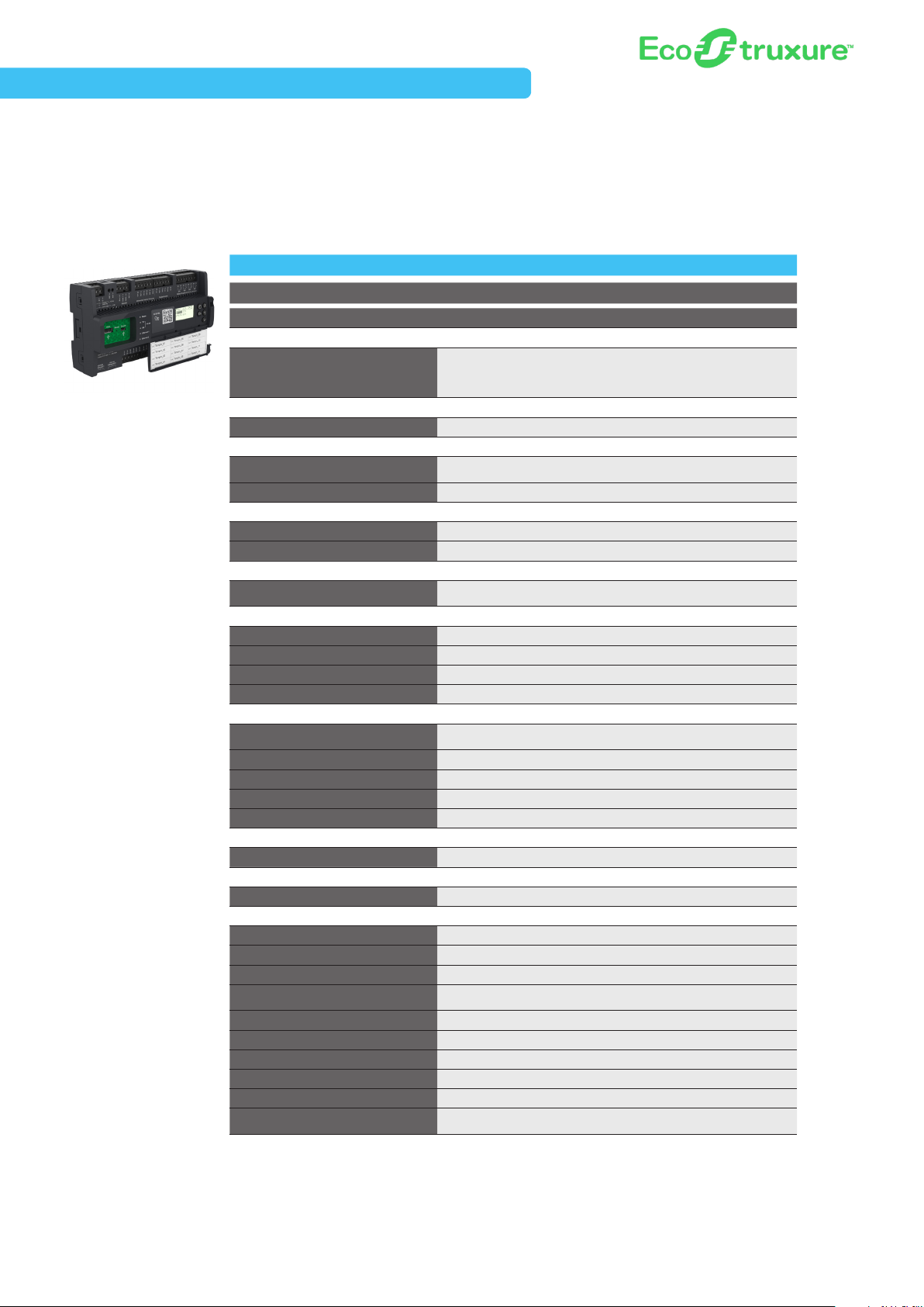
Integrated building management system

I2
Schneider Electric EcoStruxure Building

Unlock building value, unleash productivity
Next generation EcoStruxureTM Building from Schneider Electric is The Open Innovation
Platform of Buildings – a collaborative Internet of Things (IoT) solution that features a
scalable, secure and global architecture to create
future-ready smart buildings.
EcoStruxure Building securely connects hardware,
software, and services over an Ethernet IP backbone to:
+ Apps, Analytics
& Services
• Maximize building efficiency
• Optimize comfort and productivity
• Increase building value
EcoXperts™ and other system integrator partners
also benefit from many new deployment tools to
achieve:
• Up to 30% increase in engineering efficiency
• Up to 20% faster commissioning and installation
• 10x more scalability for large and multisite building needs
+ Edge Control
+ Connected Products
Get the industry’s only truly open, collaborative
IoT platform
Our latest IP-enabled hardware and software go beyond basic HVAC functions to
address the entire building ecosystem, with easy integration of devices, other building
systems, and cloud services with the performance and data-throughput needed for
the data-intensive nature of modern buildings.
Providing greater scalability and a secure, open framework, EcoStruxure Building
Operation delivers an integrated view across all building systems serving smaller
buildings to the largest and most complex multisite campuses.
EcoStruxure Building delivers Innovation At Every Level
I3
Schneider Electric EcoStruxure Building
EcoXpert™ Partner Program
One Program. One Network. Endless Opportunities.
Innovating smarter buildings, more reliable
infrastructures, and optimized efficiency.
At Schneider Electric, we constantly look beyond the norm to
provide innovative solutions, both in technology and in the way
we do business. That’s the idea behind the EcoXpert™ Partner
Program – an esteemed partnership between Schneider
Electric and more than 3,000 of the world’s leading technology
providers with best-in-class systems integration competencies.
Working with partners we trust is as important to us as it is to
our customers. Spanning more than 50 countries, EcoXpert
companies are certified on our IoT-enabled EcoStruxure™
architecture and platform, enabling them to deliver innovative
and sustainable solutions, through integrated technology and
digitization, to our shared customers.
Our mission is to connect
expertise, ignite growth
and enable success for our
EcoXpert partner companies,
because together we deliver
best-in-class services and
solutions to our valued
customers.
The EcoXpert Program enables our certified partners and
valued customers to share in the experience of ensuring that
Life Is On everywhere, for everyone, and at every moment.
Our EcoXpert partners are the implementation arms of EcoStruxure in Homes and Buildings
I4

Table of Contents
EcoStruxureTM Solution
Software ...............................................E2
User Interfaces .......................................... E4
Automation Server Family of Modules ........................ E6
SmartX Edge Server – AS-P ................................ E6
Power Supply and Module Terminal Bases .................... E7
Power Supply Selection Table ..............................E7
I/O Modules .............................................E8
I/O Modules - Inputs and Outputs .......................... E12
SmartX Edge Server – AS-B ............................... E14
SmartX Edge Server – AS-B - Inputs and Outputs ............. E15
Edge Accessories ...................................... E16
SmartX Controller – AD .................................. E16
Reference Architecture .................................. E16
SmartX IP Controller
SmartX IP Controller – MP Series ............................S3
Accessories ............................................S6
SmartX Living Space Sensors
.............................. S6
BACnet® Controllers
BACnet b3 Series ........................................B2
b3 Series Controllers .....................................B3
b3 Series xP Expansion I/O Modules ......................... B9
b3 Series Controllers - Inputs and Outputs ................... B12
b3 Series xP Expansion I/O Modules - Inputs and Outputs .....B15
MNB Series ........................................... B16
MNB Series Controllers .................................. B17
MNB Series Controllers – Inputs and Outputs ................B18
LonWorks® Controllers
Xenta™ Series .......................................... L2
Xenta Series Controllers ................................... L3
Xenta Series Programmable Controllers ...................... L7
Xenta Series I/O Modules .................................L11
Xenta Series Controllers - Inputs and Outputs .................L13
Xenta Series Programmable Controllers - Inputs and Outputs .....L15
Xenta Series I/O Modules - Inputs and Outputs ................L16
MNL Series .............................................L17
MNL Series Controllers ...................................L18
MNL Series Controllers - Inputs and Outputs ................. L22
Additional EcoBuilding Resources
Learn more about other offers ...........................A2-A9
Disclaimers
• Not all products in the guide may be available in every country, please check availability with the local Schneider Electric office.
• Some product images are not images of the exact model, but are represented by a “series” image.
• Information within this guide is subject to change without notice.
• Schneider Electric is not responsible for inadvertent typographical errors or omissions.
I5

Schneider Electric EcoStruxure Building
Flexible, personalized user
workspace
EcoStruxure solution provides an attractive, modern interface that can be
organised by individual users to suit their needs. These preferences follow
users regardless of where they log on. The information each user can
access, such as graphics and alarms, can be managed at the job function,
or individual level for added security and accountability.
E1
Software
EcoStruxure™ Building Operation
EcoStruxure™ Building Operation software is the edge
control heart of the EcoStruxure Building system to monitor,
manage and control building systems. With an open integration
platform, it securely facilitates the exchange of data from both
Schneider Electric and third-party energy, lighting, HVAC, fire
safety, security and workplace management systems to create
future-ready smart buildings.
NEW: Enterprise Central dedicated supervisory server
at the top of the EcoStruxure Building system architecture
can integrate up to 10 Enterprise Servers, hosting as many
as 2,500 SmartX Edge Servers (AS-P and AS-B) to easily
scale operations management across the largest buildings,
campuses, and multisite real estate portfolios from a single
location.
Enterprise Server, the Windows® applications version of the
Building Operation Server, is the single point of administration
through WorkStation, WebStation, and mobile applications.
Enterprise Server collects site-wide data and configures,
controls and monitors the entire system. It generates
aggregated reports, standardizes critical security policies,
normalizes alarm presentation and prioritization, and audits
activity across the entire organization.
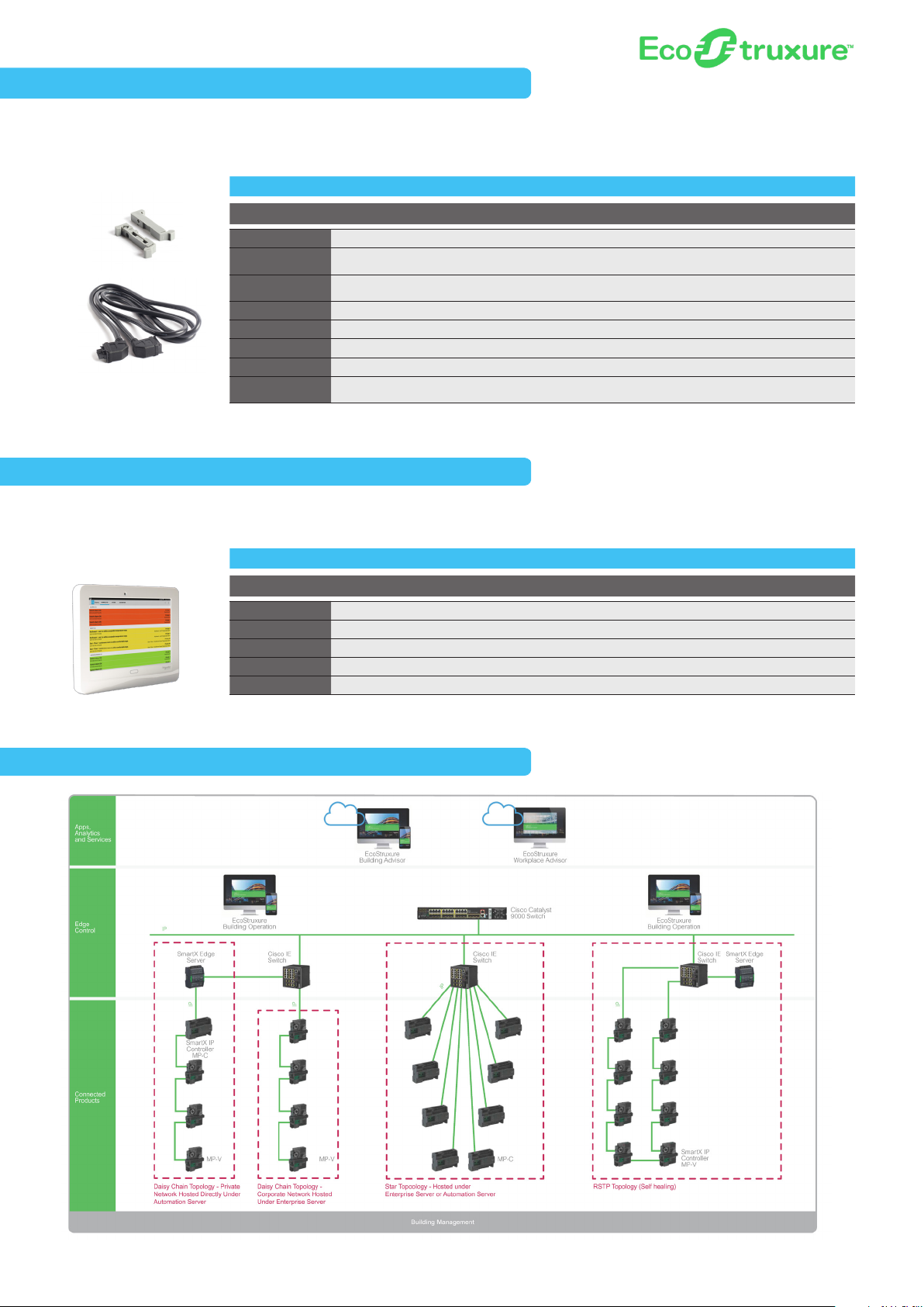
SmartX Edge Servers at the edge control level of the
architecture are automation servers for use in any application.
Including the AS-P and AS-B versions, SmartX Edge Servers
feature dual Ethernet ports to elevate BACnet field bus
communication to the IP level to modernize existing building
management systems while keeping in place existing field
buses and devices.
WorkStation interface provides users and engineers with
access to SmartX Edge Servers and Enterprise Servers to view
and manage graphics, alarms, scheduling, trend logs and
reports. WorkStation now offers a new array of engineering
efficiency tools and features to speed administrative functions,
including standard applications, mass change/mass update;
custom types and libraries, and more.
WebStation user interface provides a truly mobile experience
for anytime, anywhere access to commonly used functions of
EcoStruxure Building Operation on any platform without the
installation of additional software. Developers can now engineer
once and the workspace automatically adapts the same highquality user experience for desktop, tablet and mobile devices,
saving valuable engineering time and resources.
Smart Connector is an open, extensible and configurable
application framework that allows developers to create
innovative new capabilities, applications and solutions that
extend and enhance EcoStruxure™ Building. Smart Connector
infuses a new level of flexibility and openness by enabling
rapid, repeatable, and flexible integration with third-party
systems or other data sources systems.
SmartDriver is a custom driver for connection with other
intelligent building devices that use non-native protocols
(available with Building Operation v1.8.1 and later versions).
EcoStruxure Energy Expert is an embedded software
module that enables energy usage to be monitored, and
managed in the same system as HVAC, lighting and fire safety.
Designed specifically for non-electrical experts in buildings
with non-critical power needs.
Part Number Product Name Description
Enterprise Central
SXWSWECXX00005 Enterprise Centr al - 5
SXWSWECXX00010 Enterprise Centr al - 10
Enterprise Server
SXWSWESXX00001 Enterprise Server Pre 2.0
SXWSWESX X00010 Enterprise Server - 10
SXWSWESXX00050 Enterprise Server - 50
SXWSWESX X00100 Enterprise Server - 100
SXWSWESXX00250 Enterprise Server - 250
SXWSWASES00001 ES Hosting AS Pack -1
SXWSWNDES00005 ES Hosted Node Pack - 5 Allow the addition of 5 servers or controlle rs to any of the interfaces supporte d by the Enterprise Ser ver
SXWSWNDES00010 ES Hosted Nod e Pack - 10 Allow the addition of 10 servers or controllers to any of t he interfaces suppor ted by the Enterprise Server
SXWSWNDES00025 ES Hosted Node Pack - 25 Allow the addition of 25 servers or controllers to any of the interfaces supported by the Enterprise Ser ver
SXWSWNDES00050 ES H osted Node Pack - 50 Allow the additio n of 50 servers or controllers to any of t he interfaces suppor ted by the Enterprise Server
SXWSWNDES00100 ES H osted Node Pack - 100 Allow the addition of 10 0 server s or controllers to any of the interfaces suppor ted by the Enter prise Ser ver
SXWSWNDES00300 ES H osted Node Pack - 300 Allow the addition of 3 00 servers or controllers to any of the interf aces supported by the Enterprise S erver
SXWSWNDES00600 ES H osted Node Pack - 600 Allow the addition of 6 00 servers or controllers to any of the interf aces supported by the Enterprise S erver
The Enter prise Central is the Windows® application that aggregate s and archives data from up to 5
EcoStruxure Enterprise Servers
The Enter prise Central is the Windows® application that aggregate s and archives data from up to 10
EcoStruxure Enterprise Servers
A Window s® application version of a Building Operation Server that c ollects site-wide data for aggregation
and archi ving, yet is flexible enough to r un stand- alone applications. ( This license is for 1.X versions only.)
The Enter prise Ser ver is the Windows® app lication that aggregates and archive s data from up to 10
EcoStruxure SmartX Edge Servers
The Enter prise Ser ver is the Windows® app lication that aggregates and archive s data from up to 50
EcoStruxure SmartX Edge Servers
The Enter prise Ser ver is the Windows® app lication that aggregates and archive s data from up to 100
EcoStruxure SmartX Edge Servers
The Enter prise Ser ver is the Windows® app lication that aggregates and archive s data from up to 250
EcoStruxure SmartX Edge Servers
Allows the addition of one more SmartX Edge Server s than were supported by t he original Enterprise Server
purchased
* The Enterprise Server is BACnet B-OWS and B-BC c ertified; the testing for this cer tificati on included t he use of EcoStruxure Building Oper ation Work Station as the HMI.
E2
Schneider Electric EcoStruxure Building
Software
EcoStruxure™ Building Operation (continued)
Part Number Product Name Description
Clients
SXWSWCLIENT0001 Building Operation Client - 1
SXWSWCLIENT0999 Building Operation Client - unl
Driver
SXWSWSDRV00001
Engineering Tools
SXWSWWORK00001 WorkStation Std A full environment for operating all aspects of Eco Struxure Building Operation
SXWSWWORK00002 WorkStation Professional A full environment for operating and engineering all aspects of EcoStruxure Building Operati on
SXWSWEDIT00001
Add-On Features
SXWSWSNMP00001
SXWSWEWSX00001
SXWSWEWSX00002
SXWSWEWSX00003
SXWSWGWSX00001
EcoStruxure Energy Expert
PSWPMNCZZSPEZZ Energy Expert Base
Smart Driver License
Editors An envir onment that provides the ability to edit graphics, script programs and function block programs.
SNMP Alarming This option provide s support for SNMP alarm traps v3 .0 notifications on any SmartStr uxure ser ver.
EWS 1 A common integration m ethod to other Schneider electric systems and ser vices. Consume
EWS 2 A common integration m ethod to other Schneider electric systems and ser vices. Consume and serve
EWS 3
GWS An integration method to other systems and services
A single seat to provide a fully featured environment for operating and administering all aspects of the system
Unlimite d seats providing fully featured envir onments for o perating and administer ing all aspects of the system
Allow "drivers" to be deployed, loa ded and run on t he Enterpr ise Server and the Smar tX Controller - AS -P
A common integration m ethod to other Schneider electric systems and ser vices. Consume, ser ve and
gather history
Energy E xpert s oftware module lice nse for a PC ser ver
(no maintenance subscription included)
(*) Only supported by Managed Dev ice / BYOD Customized deploym ent method.
(**) Supported by Managed Device / BYOD Customized and Generic: this requires an unlimited devices d eployment li cense.
E3
User Interface
Functionality matrix
WorkStation Standard - WorkStation software without graphics editor, script and function block programming editors.
WorkStation Pro - WorkStation software including graphics editor, script and function block programming editors.
WebStation - Direct access to an Automation Server and/or Enterprise Server using a web browser.
WebReports - Direct access to the Reports Ser ver using a web browser.
• Full funct ionality
o Partial functionality
Alarms
View alarms • • •
Manage alarms • • •
Edit alarms • • o *2
Create alarms • •
Support for flas hing & audib le alarms • •
TM
BACnet
View pr iority array • • •
Edit pr iority a rray • • •
Create devices (includes device discovery) • •
Manag e BACnet backup and resto re • •
Graphics
View Graphics • • •
Create and edit graphics •
Logs & Ex tended Logs
View logs • • •
Edit logs • • o *4
Create logs • • o *5
View multi trend log lists • • •
Create and edit mul ti trend lo g lists • •
Export multi t rend log lists • *14 • *14 • *15
View ex tended logs • • •
Edit extended logs • • o *4
Create extended logs • •
LON
Create devices (includes device discovery) • •
Manage devices • •
View Ne twork Variables (NVs) an d
Configuration Parameters (CPs)
Edit NVs and CPs • • •
®
Modbus
Create devices • •
Manage devices • •
View values • • •
Edit values • • •
Point Values - e.g. Temperature Setpoint
View values • • •
Edit values - e.g. "cha nge setpoint" • • •
rograms
P
Create and edit customised programs •
View graphical function block viewer • •
Program MNL/MNB controllers • *7
WorkStation
Standard
• • •
WorkStation Pro WebStation WebReports
* 1 Supports alarm acknowledgement.
* 2 Edit alarm ranges, text , delay times, shunt varia bles, assignments, deadband.
* 3 View in list fo rmat.
* 4 Change par ameters - e.g. in terval time.
* 5 Create inter val log type.
* 6 NVs and CPs are displayed on ly in SI units.
* 7 Microsof t® Visio required
E4
Schneider Electric EcoStruxure Building
User Interface
Functionality matrix, continued
• Full funct ionality
o Partial functionality
Reports
View reports • • • •
Edit reports • • • *8 •
Create & configure reports • •
Administer reports •
Schedules & Calendars
View schedules and calendars • • •
Edit schedules and calendars • • o *9
Create schedules and calendars • •
Users & Us er Groups
Create and edit use rs • • o *10
Create and edit use r's group m embersh ip • • o *10
Create and edit groups • •
Create and edit permissions • •
User Experience
View customised workspaces • • •
Log on as windows Active Directory user • • •
Automatic guest account log on •
Password management • • •
Create and edit save d searches • •
View saved search • • •
Ad hoc sea rch • • •
Kiosk mode •
Bookmarking to a particu lar web view • •
Support for localisation • • •
Support for translation •
Abili ty to change languag e on the clie nt
side
Other
Configure & edit I/O p oints, fie ld buses, and
communication ports
Create and edit log ical str ucture • •
Create and edit vie wers, panels and
workspaces
View & configure Watch pane • • o *13
View events • • •
Administer backup/restore of database • •
Manage archiving • •
WorkStation
Standard
• • •
• •
• •
WorkStation Pro WebStation WebReports
• *11 • o *12
* 8 Edit some par ameters pe r report , save changes or make a copy of th e report w ith change s.
* 9 Edit existin g only; cannot create or edi t recurri ng calendar events.
*10 Cannot assig n permissions.
*11 Translation is only supporte d in the WorkS tation inte rface; it i s not suppor ted for grap hics and pro gramming ed itors.
*12 Report tex t can be edited and translated using a Report Defi nition Lan guage (RDL) e ditor such as Microsoft ® Repor t Builder.
*13 Configuration change s cannot be saved.
*14 Expor t to XML and CS V files suppor ted.
*15 Expor t to Microsof t Excel file s upporte d in EcoStr uxure Buil ding Operat ion versio n 2.0.2 and later.
E5
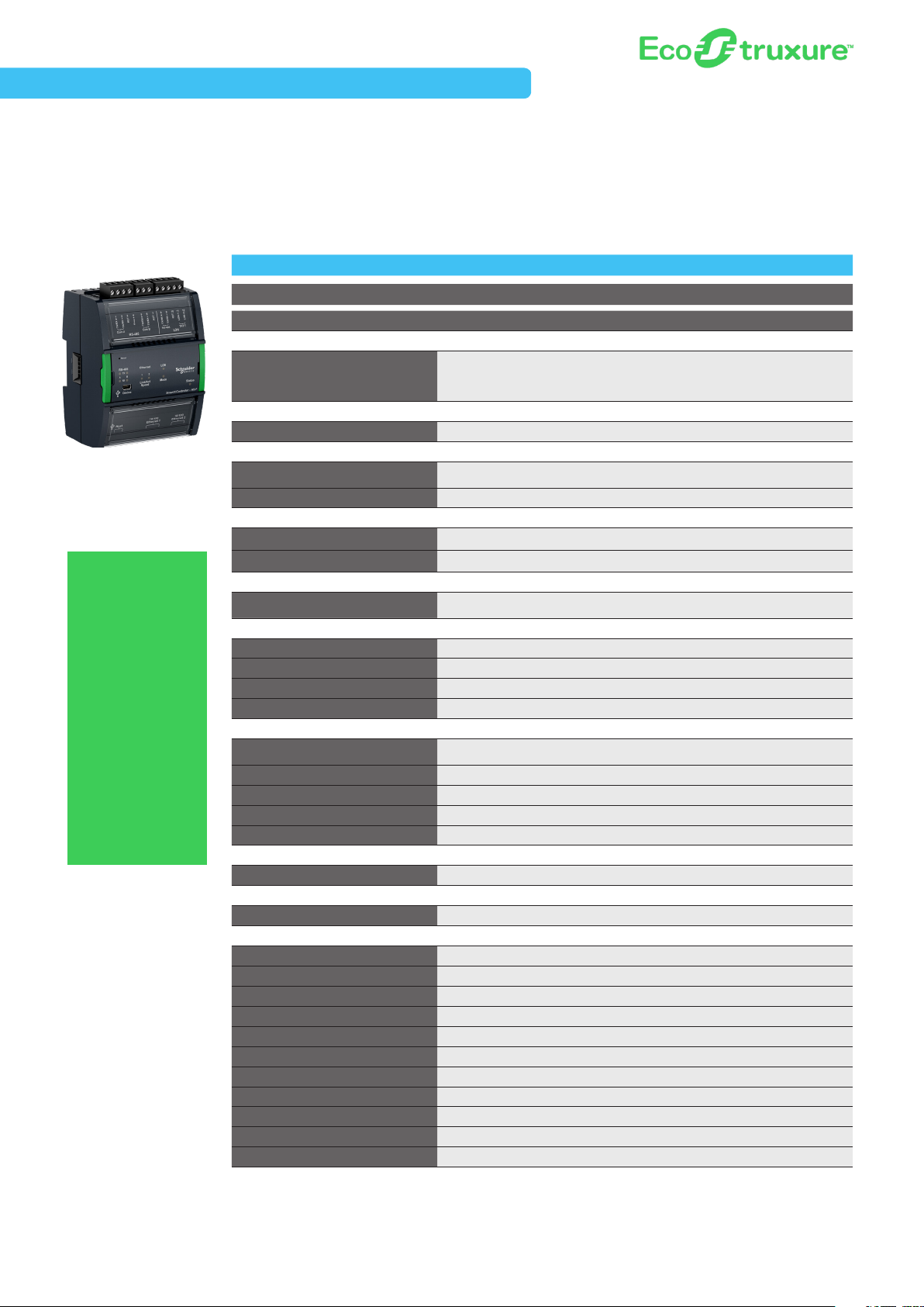
Automation Server Family of Modules
SmartX Edge Server – AS-P
The SmartX Edge Ser ver – AS-P is a EcoStruxure server device at the Edge Level of the architecture. With superior performance,
the AS-P simplifies system integration and transition, and is the preferred choice for large, complex enterprise applications.
AS-P ASP-SMK
Part Number SXWASPXXX10001 SWXASPXXX1S001
Communications
Smar tX Edge Server – AS-P
The SmartX Edge
Server – AS-P
and AS-B feature
dual Ethernet
ports to elevate
BACnet field bus
communication
to the IP level.
Modernize the
BMS while keeping
in place legacy
field buses and
devices to futureready current
systems and move
buildings into the
21st century!
LonWorks FTT-10, BACnet/IP, BACnet MS/
Communication Interface
Software
Programability Function Block/Script Programmable Function Block/Script Programmable
Physical
Dimensions
Weight (including baseplate) 0.245 kg (0.54 lb) 0.245 kg (0.54 lb)
Power
Power 24 VDC 24 VDC
Consumption 10 W 10 W
Environmental
Operating Range
CPU Internals
CPU SPEAr320S, ARM926 core SPEA r320S, A RM926 core
Memory 4 GB 4 GB
Battery
Real time clock Yes -10 days backup/Super Capacitor Yes -10 days backup/Super Capacitor
External Features
Enclosure rating
HOA Switches (DO/AO) N/A N/A
Manual Overrid e of Outputs N/A N/A
Digital Status LEDs Yes Yes
Service Port Yes Yes
Terminals
I/O Expansion Yes - Up to 29 modules/464 max I/O Yes - Up to 29 modules/464 max I/O
External Enclosure/Mounting
Mounting
Certifications
BTL Yes Yes
FCC 47 CFR § 15, Class B (Emission) 47 CFR § 15, Class B (Emission)
Industry Canda (IC) ICES-003 (Emission) ICES-003 (Emission)
UL UL-916 (Energy Management Equipment) UL-916 (Energy Management Equipment)
C-UL US Yes Yes
CE - EU Yes Yes
WEEE - Directive of the Europe an Union Yes Yes
RoHS Directive Ye s Ye s
RCM Yes Yes
US Patent 8 207 842, 8 271 102, 7 994 438 8 207 842, 8 271 102, 7 994 438
UL-864 No Yes
*Notes: EcoStruxure solution installations or BMS transitions requiring UL-864 certifications must use the Smar tX Controller AS-PSMK (listed above).
SmartX Controller - AS- P and AS- B conform to the BACnet® Building C ontroller (B-BC) profile at protocol revision 12 by the
BACnet Testing Laboratories (BTL
®
TP, Modbus TCP (Client+Server), Modbus
serial (Master+Slave), EW S, Generic
WebSevice consume
90 W x 114 H x 64 D mm
(3.60 W x 4.5 0 H x 2.50 D in.)
0°C to 50 °C (32°F to 122°F) 0-95% RH
(non-condensing)
No No
Eco Friendly ABS/PC, UL94 5VB, IP 20 (<12.5
mm pr otec tion)
DIN- rail or wall mount DIN-rail or w all mount
). StruxureWare™ Building Operation v1.9 is the certified firmware revision.
LonWorks FTT-10, BACnet/IP, BACnet MS/
TP, Modbus TCP (Client+Server), Modbus
serial (Master+Slave), EW S, Generic
WebSevice consume
90 W x 114 H x 64 D mm
(3.60 W x 4.5 0 H x 2.50 D in.)
0°C to 50 °C (32°F to 122°F) 0-95% RH
(non-condensing)
Eco Friendly ABS/PC, UL94 5VB, IP 20 (<12.5
mm pr otec tion)
E6
Schneider Electric EcoStruxure Building
Automation Server Family of Modules
Power Supply and Module Terminal Bases
The PS-24V is a power supply module that accommodates 24 VAC or 24 VDC input power. Each power supply module delivers
reliable and consistent output power of 24 VDC to the backplane. It can deliver power to the AS-P and a number of I/O modules
calculated from the Power Budget Table (located below). If more I/O modules are needed, another power supply can be added to the
bus. The power supplies are isolated from each other while also providing communication pass-through.
Part Number Product Name Description
SXWPS24VX10001 PS-24V Power Suppl y 24 VAC or 21-30 VDC
SXWTBPSW110001 TB- PS-W1 Terminal Base Power Supply (Terminal Base required for each power supply)
SXWTBASW110002 TB-ASP-W1 Terminal Base AS-P ( Terminal base required for each AS-P)
SXWTBIOW110001 TB-IO- W1 Terminal Base I /O (Terminal Base required for each I/O module)
Automation Server Power Supply
PS-24V
NOTE: An appropriate terminal base is required for each module, including the AS-P, Power Supply
and I/O Modules. See the above table for the correct part numbers.
Terminal Base and Module Detail
I/O Module
Power Supply Selection Table
Power Requirements
Smar tX Edge Server – AS -P
Smar tX Edge Server – AS -B
Power Req uirements - Input onl y I/O
DI-16 1.6 W
RTD -DI -16 1.6 W
UI-16 1.8 W
Power Req uirements - Output o nly I/O
DO -FA-12 1.8 W
DO-FA-12-H 1.8 W
DO- FC-8 2.2 W
DO-FC-8-H 2.2 W
AO-8 4.9 W
AO-8-H 4.9 W
AO-V-8
AO-V-8 -H
Power Req uirements - Mixed I/O
UI-8/DO-FC-4 1.9 W
UI-8/DO-FC-4 -H 1. 9 W
UI- 8/AO- 4 3.2 W
UI- 8/AO- 4-H 3.2 W
UI-8/AO-V-4 1.0 W
UI-8/AO-V-4-H 1.0 W
24 VDC / 10 W 24 VAC / 15 VA
24 VDC / 10 W
24 VDC Power
24 VDC Power
0.7 W
0.7 W
24 VDC Power
Please refer to the appropriate Dat a Sheets for more information.
E7

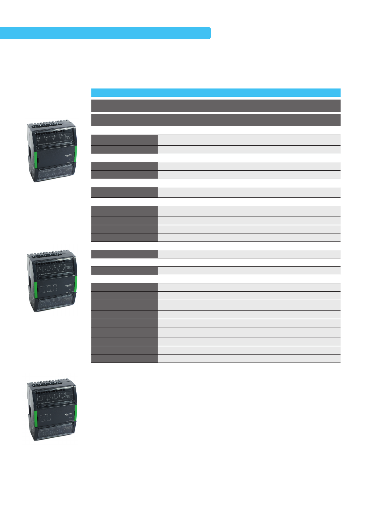
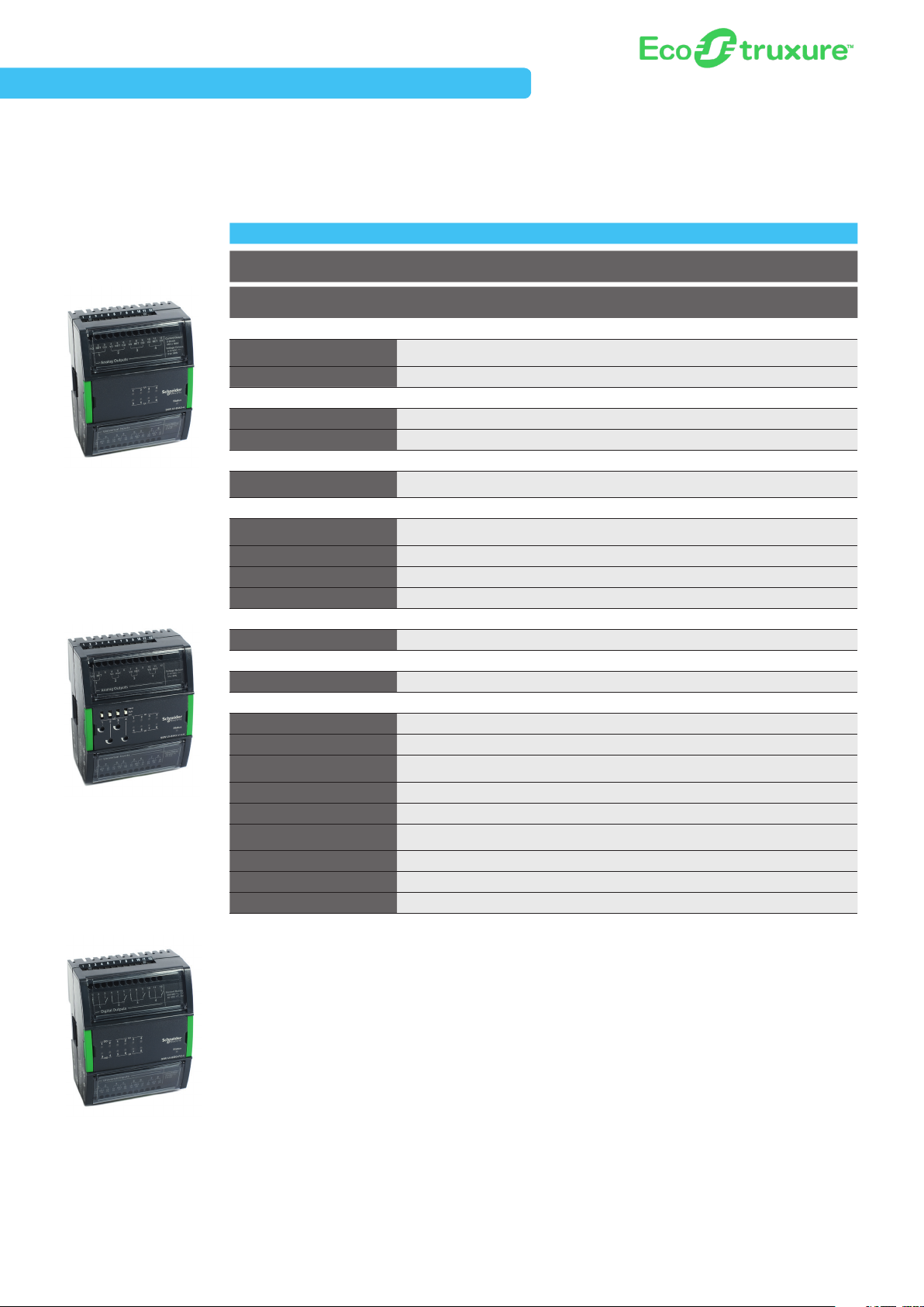
Automation Server Family of Modules
I/O Modules
The Automation Server includes support for a broad spectrum of I/O modules. The variety of modules available ensures the right
combination of points for any project, which keeps costs down for our customers. Some modules are available with Hand/Off/Auto
(HOA) switches to provide override control of the outputs.
16 Channel Universal Input
UI -16
DI -16
16 Channel Digital Input
UI-16 D I-16
Part Number
Physical
Dimensions
Weight (including baseplate) 0.269 kg (0.5 9 lb.) 0. 255 kg (0.56 lb.) 0.279 kg (0.62 lb.)
Power
Power 24 VDC 24 V DC 24 VDC
Consumption 1.8 W 1.6 W 0.7 W
Environmental
Operating Range
External Features
Enclosure rating
HOA Switches (DO/AO) No No Available on -H model
Digital Status LEDs Yes Yes No
Service Port No No No
Terminals
I/O Terminals Terminal base Terminal base Terminal base
External Enclosure/Mounting
Mounting D IN-rail or wall mount DIN-rail or wall mount DIN-rail or wall mount
Certifications
FCC 47 CFR § 15, Cla ss B (Emission) 47 CFR § 15, Class B (Emission) 47 CFR § 15, Class B (Emission)
Industry Canada (IC) ICES-003 (Emission) ICES-0 03 (Emission) ICES-003 (Emission)
UL
C-UL US No No No
CE - EU Yes Yes Yes
WEEE - Directive of the Europe an
Union
RoHS Directive Yes Yes Yes
RCM Yes Yes Yes
US Patent 7 9 94438 7 994438 7 994438
SXWUI16XX10001 SXWDI16XX10001
90 W x 114 H x 64 D mm
(3.60 W x 4.5 0 H x 2.50 D in.)
0 °C to 50 °C (32 ° F to 122 °F)
0-95% RH (non-condensing)
Eco Friendly ABS/PC, UL94 5VB,
IP 20 (<12.5 mm protection)
UL-916 (Energy Management
Equipment)
Yes Yes Yes
90 W x 114 H x 64 D m m
(3.60 W x 4.5 0 H x 2.50 D in.)
0 °C to 50 °C (32 ° F to 122 °F)
0-95% RH (non-condensing)
Eco Friendly ABS/PC, UL94 5VB,
IP 20 (<12.5 mm protection)
UL-916 (Energy Management
Equipment)
90 W x 114 H x 64 D m m
(3.60 W x 4.5 0 H x 2.50 D in.)
0 °C to 50 °C (32 ° F to 122 °F)
0-95% RH (non-condensing)
Eco Friendly ABS/PC, UL94 5VB,
IP 20 (<12.5 mm protection)
UL-916 (Energy Management
Equipment)
AO-8,
AO-8-H
SXWAO8XXX10001,
SXWAO8HXX10001
AO-8, AO-8 -H
8 Channel Analog Out put
E8
Schneider Electric EcoStruxure Building
Automation Server Family of Modules
I/O Modules, continued
AO-V- 8 , AO-V-8 -H
8 Channel Analog Out put
Voltage Points
DO- FA-12 , DO-FA-12-H
12 Channel Digital Output,
Form-A
AO - 8-V,
AO-8-V-H
Part Number
Physical
Dimensions
Weight (including baseplate) 0.279 kg (0.62 lb.) 0.317 kg (0.70 lb.) 0.332 kg (0.73 lb.)
Power
Power 24 VDC 24 V DC 24 VDC
Consumption 0.7 W 1.8 W 2.2 W
Environmental
Operating Range
External Features
Enclosure rating
HOA Switches (DO/AO) Available on -H model Available o n -H model Available on -H model
Digital Status LEDs No Yes Ye s
Service Port No No No
Terminals
I/O Terminals Terminal base Terminal base Terminal base
External Enclosure/Mounting
Mounting D IN-rail or wall mount DIN-rail or wall mount DIN-rail or wall mount
Certifications
FCC 47 CFR § 15, Cla ss B (Emission) 47 CFR § 15, Class B (Emission) 47 CFR § 15, Class B (Emission)
Industry Canada (IC) ICES-003 (Emission) ICES-0 03 (Emission) ICES-003 (Emission)
UL
C-UL US No No Ye s
CE - EU Yes Yes Yes
WEEE - Directive of the Europe an
Union
RoHS Directive Yes Yes Yes
RCM Yes Yes Yes
US Patent 2002/96/EC 2002/96/EC 2002/96/EC
SXWAOV8XX10001,
SXWAOV8HX10001
90 W x 114 H x 64 D m
(3.60 W x 4.5 0 H x 2.50 D in.)
0 °C to 50 °C (32 ° F to 122 °F)
0-95% RH (non-condensing)
Eco Friendly ABS/PC, UL94 5VB,
IP 20 (<12.5 mm protection)
UL-916 (Energy Management
Equipment)
Yes Yes Yes
m
DO -FA-12 ,
DO-FA-12-H
SXWDOA12X10001,
SXWDOA12H10001
90 W x 114 H x 64 D m m
(3.60 W x 4.5 0 H x 2.50 D in.)
0 °C to 50 °C (32 ° F to 122 °F)
0-95% RH (non-condensing)
Eco Friendly ABS/PC, UL94 5VB,
IP 20 (<12.5 mm protection)
UL-916 (Energy Management
Equipment)
DO-FC-8,
DO-FC-8-H
SXWDOC8XX10001,
SXWDOC8HX10001
90 W x 114 H x 64 D m m
(3.60 W x 4.5 0 H x 2.50 D in.)
0 °C to 50 °C (32 ° F to 122 °F)
0-95% RH (non-condensing)
Eco Friendly ABS/PC, UL94 5VB,
IP 20 (<12.5 mm protection)
UL-916 (Energy Management
Equipment)
DO- FC-8, D O-FC-8-H
8 Channel Digital Out put,
Form-C
E9
Automation Server Family of Modules
I/O Modules, continued
UI- 8/AO- 4, UI- 8/AO- 4-H
8 Channel Universal Inputs
with 4 Analog Outputs
UI- 8/AO-V- 4, UI- 8/AO-V-4- H
8 Channel Universal Inputs
with 4 Channel Voltage
Outputs
(UI-8/AO-V-4-H shown)
UI- 8/AO-4,
UI- 8/AO-4-H
Part Number
Physical
Dimensions
Weight (including baseplate) 0.276 kg (0.61 lb.) 0.276 kg (0. 61 lb.) 0.3 04 kg (0.67 lb.)
Power
Power 24 VDC 24 V DC 24 VDC
Consumption 3.2 W 1.0 W 1. 9 W
Environmental
Operating Range
External Features
Enclosure rating
HOA Switches (DO/AO) Available on -H model Available o n -H model Available on -H model
Digital Status LEDs Yes Yes Yes
Service Port No No No
Terminals
I/O Terminals Terminal base Terminal base Terminal base
External Enclosure/Mounting
Mounting D IN-rail or wall mount DIN-rail or wall mount DIN-rail or wall mount
Certifications
FCC 47 CFR § 15, Cla ss B (Emission) 47 CFR § 15, Class B (Emission) 47 CFR § 15, Class B (Emission)
Industry Canada (IC) ICES-003 (Emission) ICES-0 03 (Emission) ICES-003 (Emission)
UL
C-UL US Yes Yes Yes
CE - EU Yes Yes Yes
WEEE - Directive of the Europe an
Union
RoHS Directive Yes Yes Yes
RCM Yes Yes Yes
US Patent 7 9 94438 7 9944 38 7 994438
SXWUI8A4X10001,
SXWUI8A4H10001
90 W x 114 H x 64 D m m
(3.60 W x 4.5 0 H x 2.50 D in.)
0 °C to 50 °C (32 ° F to 122 °F)
0-95% RH (non-condensing)
Eco Friendly ABS/PC, UL94 5VB,
IP 20 (<12.5 mm protection)
UL-916 (Energy Management
Equipment)
Yes Yes Yes
UI- 8/AO-V- 4,
UI- 8/AO-V- 4-H
SXWUI8V4X10001,
SXWUI8V4H10001
90 W x 114 H x 64 D m m
(3.60 W x 4.5 0 H x 2.50 D in.)
0 °C to 50 °C (32 ° F to 122 °F)
0-95% RH (non-condensing)
Eco Friendly ABS/PC, UL94 5VB,
IP 20 (<12.5 mm protection)
UL-916 (Energy Management
Equipment)
UI-8/DO-FC-4,
UI-8/DO-FC-4-H
SXWUI8D4X10001,
SXWUI8D4H10001
90 W x 114 H x 64 D m m
(3.60 W x 4.5 0 H x 2.50 D in.)
0 °C to 50 °C (32 ° F to 122 °F)
0-95% RH (non-condensing)
Eco Friendly ABS/PC, UL94 5VB,
IP 20 (<12.5 mm protection)
UL-916 (Energy Management
Equipment)
UI-8/DO- FC-4, U I-8/DO-FC -4-H
8 Channel Universal Inputs with 4
Channel Digital Out puts, Form -C
E10
Schneider Electric EcoStruxure Building
Automation Server Family of Modules
I/O Modules, continued
Part Number
Physical
Dimensions
Weight (including baseplate) 0.269 kg (0.5 9 lb.)
Power
Power 24 VDC
Consumption 1.6 W
Environmental
Operating Range
RT D- DI -16
16 Channel Inputs (RTD and
Digital) Combination Module
External Features
Enclosure rating
HOA Switches (DO/AO) No
Digital Status LEDs Yes
Service Port No
Terminals
I/O Terminals Terminal base
External Enclosure/Mounting
Mounting D IN-rail or wall mount
Certifications
FCC 47 CFR § 15, Cla ss B (Emission)
Industry Canada (IC) ICES-003 (Emission)
UL
C-UL US Yes
CE - EU Yes
WEEE - Directive of the Europe an
Union
RoHS Directive Yes
RCM Yes
US Patent 7 9 94438
RTD-DI-16
SXWRTD16X10001
90 W x 114 H x 6 4 D m
(3.60 W x 4.5 0 H x 2.50 D in.)
0 °C to 50 °C (32 ° F to 122 °F)
0-95% RH (non-condensing)
Eco Friendly ABS/PC, UL94 5VB, IP
20 (<12.5 mm protection)
UL-916 (Energy Management
Equipment)
Yes
m
E11
Automation Server Family of Modules
I/O Modules - Inputs and Outputs
UI-16 DI-16
Part Number
Universal Inputs 16
Digital Contact
Digit al Counter - Low Speed
Digital Counter - Medium Speed
Digit al Counter - High Speed
Digital Supervised
Analog Voltage - 0-1 V
Analog Voltage - 0-5 V
Analog Voltage - 0-10 V
Analog Voltage - 2-10 V
Analog Current - 0 -20 mA
Analog Current - 4 -20 mA
Analog Resistance
Analog Thermis tor - 10 k
Analog Thermis tor - 1.8 k
Analog Thermis tor - 1 k
Analog Thermis tor - 20 k
Analog Thermis tor - 2.2 k
Analog RTD - Pt100
Analog RTD - Pt1000
Analog RTD - Ni1000
Analog RTD - LG Ni1000
Digital Inputs 16
Digital Contact
Counte r - Low Speed
Counter - Medium Speed
Counte r - High Speed
Digital Outputs 12 8
Form A, SPST
Form C, SPDT
Tri ac
Analog Outputs 8 8
Voltage - 0-10 V
Current - 0-20 mA
SXWUI16XX10001
•
•
•
•
•
•
•
•
•
•
•
•
•
•
•
SXWDI16XX10001
•
•
AO-8,
AO-8-H
SXWAO8XXX10001,
SXWAO8HXX10001
• •
•
AO - 8-V,
AO-8-V-H
SXWAOV8X X10001,
SXWAOV8HX10001
DO -FA-12 ,
DO-FA-12-H
SXWDOA12X10001,
SXWDOA12H10001
•
DO-FC-8,
DO-FC-8-H
SXWDOC8XX10001,
SXWDOC8HX10001
•
E12
Schneider Electric EcoStruxure Building
Automation Server Family of Modules
I/O Modules - Inputs and Outputs, continued
UI- 8/AO-4,
UI- 8/AO-4-H
Part Number
Universal Inputs 8 8 8 16*
Digital Contact
Digit al Counter - Low Speed
Digital Counter - Medium Speed
Digit al Counter - High Speed
Digital Supervised
Analog Voltage - 0-1 V
Analog Voltage - 0-5 V
Analog Voltage - 0-10 V
Analog Voltage - 2-10 V
Analog Current - 0 -20 mA
Analog Current - 4 -20 mA
Analog Resistance
Analog Thermis tor - 10 k
Analog Thermis tor - 1.8 k
Analog Thermis tor - 1 k
Analog Thermis tor - 20 k
Analog Thermis tor - 2.2 k
Analog RTD - Pt100
Analog RTD - Pt1000
Analog RTD - Ni1000
Analog RTD - LG Ni1000
Digital Inputs
Digital Contact
Counte r - Low Speed
Counter - Medium Speed
Counte r - High Speed
Digital Outputs 4
Form A, SPST
Form C, SPDT
Tri ac
Analog Outputs 4 4
Voltage - 0-10 V
Current - 0-20 mA
SXWUI8A4X10001,
SXWUI8A4H10001
• • • •
• • • •
• • •
• • •
• • •
• • •
• • •
• • •
• • •
• • • •
• • •
• • •
• • •
• • •
• • •
• •
•
UI- 8/AO-V- 4,
UI- 8/AO-V- 4-H
SXWUI8V4X10001,
SXWUI8V4H10001
UI-8/DO-FC-4,
UI-8/DO-FC-4-H
SXWUI8D4X10001,
SXWUI8D4H10001
•
RTD-DI-16
SXWRTD16X10001
•
•
•
•
E13
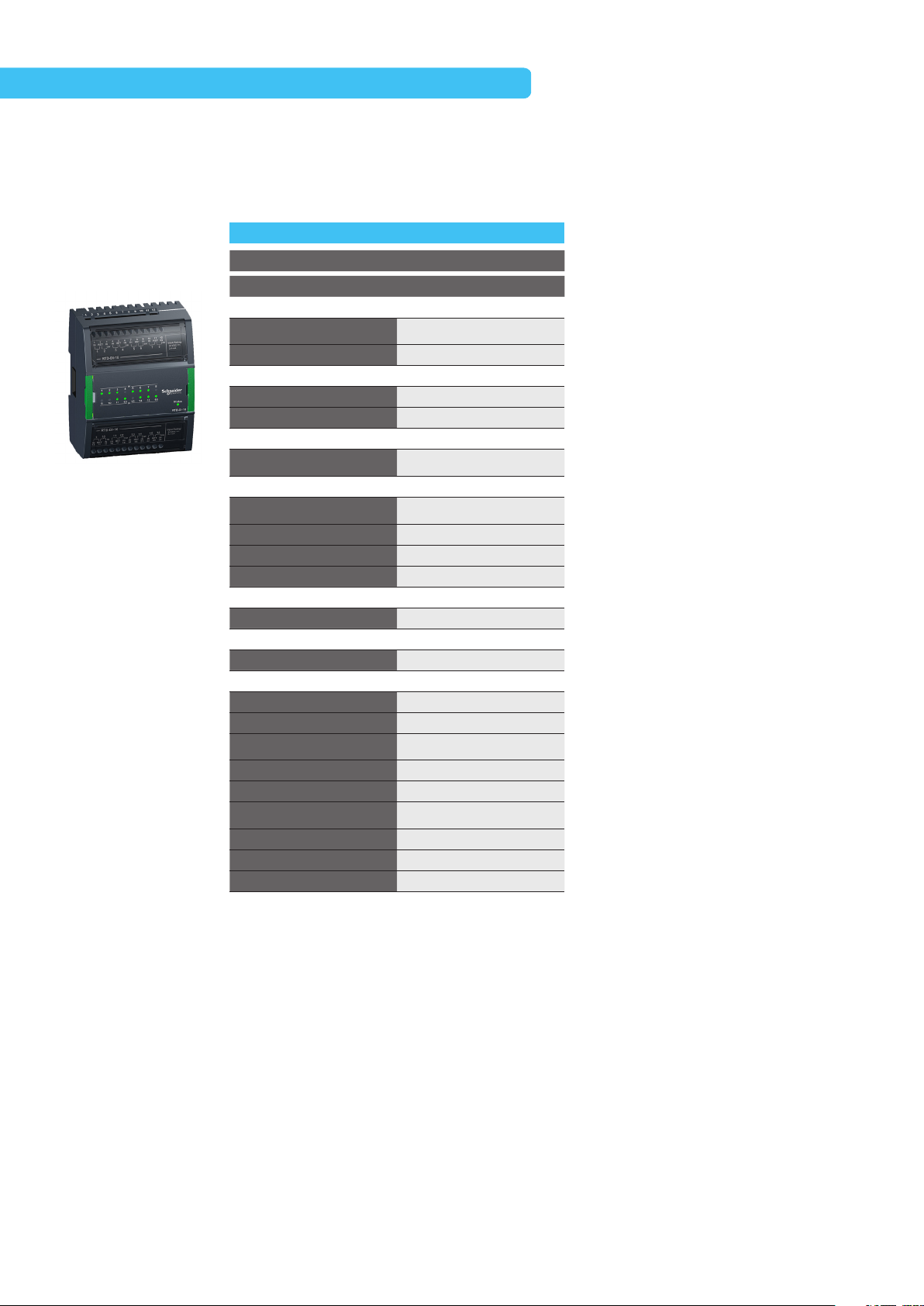
Automation Server Family of Modules
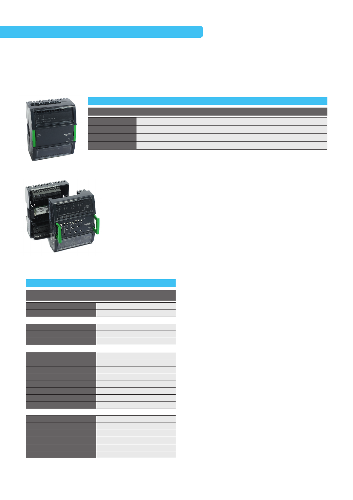
SmartX Edge Server – AS-B
The SmartX Edge Ser ver – AS-B is the most compact, all-in-one BMS. It features flexible on-board universal I/O configurations
and built-in power supply. An EcoStruxure server device, its power ful, compact design is ideal for small-to-medium main plant
control applications. It offers lower total installation costs.
AS-B-24(H) AS-B-36(H)
Smar tX Edge Server – AS-B
Note: Screw terminal
blocks for the AS-B
and AS- BL must be
ordered separately.
Please find the
AS-B Connector Kit
part number in the
Accessories section
on page E16.
Part Number
Communications
Communication Interface
Software
Programmability Function Block/Script Programmable Function Block/Script Programmable
Physical
Dimensions
Weight (including baseplate)
Power
Power
Consumption
Environmental
Operating Range
CPU Internals
CPU
Memory
Battery
Real time clock
External Features
Enclosure rating
HOA Switches (DO/AO)
Manual Overrid e of Outputs
Digital Status LEDs
Service Port Yes Yes
Terminals
I/O Expansion No No
External Enclosure/Mounting
Mounting
Certifications
BTL
FCC
Industry Canada (IC)
UL
C-UL US
CE - EU
WEEE - Directive of the Europe an Union
RoHS Directive
RCM
US Patent
SXWASB24(X,H)10001 SXWASB36(X,H)10001
BACnet/IP, BACnet MS/TP, Modbus
TCP (Client+Server), Modbus serial
(Master+Slave), EWS, Generic
WebSevice consume
198 W x 110 H x 64 D m m
(7.8 W x 4.3 H x 2.5 D in.)
0.504 kg (1.111 lb)
24 VAC/ DC
10 W
0°C to 50 °C (32°F to 122°F) 0-95% RH
(non-condensing)
SPEA r320S, A RM926 core SPEAr32 0S, ARM926 core
4 GB
No No
Yes -10 days backup/Super Capacitor Yes -10 days backup/Super Capacitor
Eco Friendly ABS/PC, UL94 5VB, IP 20
(<12.5 mm protection)
N/A
Yes - On 'H' model
Yes
DIN- rail or wall mount DIN-rail o r wall mount
Yes Yes
47 CFR § 15, Class B (Emission) 47 CFR § 15, Class B (Emission)
ICES-0 03 (Emission)
UL-916 (Energy Management
Equipment)
Yes
Yes
Yes
Yes
Yes
8 207 842, 8 271 102,
7 994 438
BACnet/IP, BACnet
MS/ TP, Modbus TCP (Client+Server),
Modbus serial (Master+Slave), EWS,
Generic WebSevice consume
198 W x 110 H x 64 D m m
(7.8 W x 4.3 H x 2.5 D in.)
0.504 kg (1.111 lb)
24 VAC/ DC
10 W
0°C to 50 °C (32°F to 122°F) 0-95% RH
(non-condensing)
4 GB
Eco Friendly ABS/PC, UL94 5VB, IP 20
(<12.5 mm protection)
N/A
Yes - On 'H' model
Yes
ICES-0 03 (Emission)
UL-916 (Energy Management
Equipment)
Yes
Yes
Yes
Yes
Yes
8 207 842, 8 271 102,
7 994 438
*Notes: EcoStruxure Building installations or BMS transitions requiring UL-864 certifications must use the SmartX Edge Server
AS- P-SMK (see page E6).
SmartX Edge Ser ver - AS-P and AS-B conform to the BACnet® Building C ontroller (B-BC) profile at protocol revision 12 by the
BACnet Testing Laboratories (BTL
®
). EcoStr uxure™ Building Operation v1.9 is the certified firmware revision.
E14
Schneider Electric EcoStruxure Building
Automation Server Family of Modules
SmartX Edge Server – AS-B – Inputs and Outputs
AS-B-24(H) AS-B-36(H)
Part Number
Universal Inputs/Outputs
Digital Contact
Digit al Counter - Low Speed
Digital Counter - Medium Speed • •
Digit al Counter - High Speed
Digital Supervised
Analog Voltage - 0-1V
Analog Voltage - 0-5V
Analog Voltage - 0-10V
Analog Voltage - 2-10V
Analog Current - 0 -20mA
Analog Current - 4 -20mA Ub Ub
Analog Resistance
Analog Thermis tor - 10k
Analog Thermis tor - 1.8k
Analog Thermis tor - 1k
Analog Thermis tor - 20k
Analog Thermis tor - 2.2k
Analog RTD - Pt100
Analog RTD - Pt1000
Analog RTD - Ni1000
Analog RTD - LG Ni1000
Digital Inputs 4
Digital Contact •
Counte r - Low Speed
Counter - Medium Speed
Counte r - High Speed
Digital Outputs 4 8
Form A, SPST • 4
Form C, SPDT
PWM • •
Tri ac
SXWASB24(X,H)10001 SXWASB36(X,H)10001
12-Ua 4-Ub 20-Ua 8-Ub
Ua/Ub Ua/Ub
Ua/Ub Ua/Ub
Ua/Ub Ua/Ub
Ua/Ub Ua/Ub
Ua/Ub Ua/Ub
Ua/Ub Ua/Ub
Ub Ub
Ua/Ub Ua/Ub
Ua/Ub Ua/Ub
Ua/Ub Ua/Ub
Ua/Ub Ua/Ub
Ua/Ub Ua/Ub
Ua/Ub Ua/Ub
Ua/Ub Ua/Ub
Ua/Ub Ua/Ub
Ua/Ub Ua/Ub
4
Key:
Ua – Universal Type A
Ub – Universal Type B
I – Input
O – Outpu t
E15
Automation Server Family of Modules
Accessories
The following accessories are available for the Automation Server Family of modules.
Part Number Product Name Description
SXWDI NEND10001 DIN-R AIL-CLIP-25 DIN-Rail End Clip, package of 25 pieces
SX WT ER LB L10 011 PRINTOUT-A4-W1
SX WT ER LB L10 01 2 PRINTOUT-LTR-W1
SXWSCABLE10002 S-CABLE-L-1.5M S-Cable extension cord for Automation Server I/O bus, L shaped co nnectors, 1.5 m
SXWSCABLE10003 S-CABLE-L-0.75M S-Cable extension cable for Automation S erver I/O bus, L-shaped connectors, 0.75 m
SXWASBCON10001 AS-B connector kit Screw terminals for all AS-B models. Note: Ordered separately, not delivered with the controller
SXWASBINS10001 AS-B installer kit Dummy unit, no electronics, just terminals. Supports easy wiring in the panel shop
SXWUSBADP10001
USB- 485-INET
Interface Adapter
SmartX Controller – AD (Advanced Display)
Portable or permanent-mount tablet HMI specifically configured to interact with EcoStruxure Building user interfaces.
A4- Size blank pr intable adhesive label sheets for ter minals
(100 Sheets, 18 labels per She et)
Letter-size blank printable adhe sive label sheets for terminals
(100 Sheets, 16 labels per Sheet)
I/NE T Adapter: Seperate hardware component, added to a Smart X Controller - AS-P or
Automation Server
Part Number Product Name Description
SXWADBUND10002 Advanced Display 10-inch Bundle Includes tablet, mounting frame, and bezel
SXWADUSBA10001 USB cable, 1.5 m (5 ft) For conne ction to AS -P or USB power adapter
SXWADUSBA10002 USB cable, 3.0 m (10 ft) For connection to AS -P or USB p ower adapter
SXWADUSBB10001 USB cable, Y-shaped, 1.5 m (5 ft) For conne ction to automation ser ver and USB power adapter
SXWADUSBB10002 USB cable, Y-shaped, 3.0 m (10 ft) For conne ction to automation ser ver and USB power adapter
Reference Architecture
E16

E17
Schneider Electric EcoStruxure Building

SmartX IP Controller
Schneider Electric EcoStruxure Solution
S1
S1

Schneider Electric EcoStruxure Building
SmartX IP Controllers
Next-generation IP field controllers and accessories
extend the reach of EcoStruxure Building’s open
innovation platform with seamless scalability and
flexible topologies that enable data transmission from
connected equipment, and enhance the ability to
diagnose and resolve issues faster.
S2

SmartX IP Controller
SmartX IP Controllers – MP Series
The MP Series, first in the SmartX IP Controllers offer, are designed for VAVs and fan coil, heat pump, roof top and air handling units.
They feature scalable and flexible topologies that enable data transmission from connected equipment, which enhance the ability to
diagnose and resolve issues faster. Also manage commissioning activities conveniently from mobile devices with the eCommission
SmartX IP Controller Mobile App.
Smar tX IP Cont roller – MP- C
Note: Screw terminals
are prepopulated.
Spare is available.
See accessories
section on page S6.
MP-C-15A
Part Number
Communications
Communication Interface
Software
Programability
Physical
Dimensions
Weight (including terminal
bloc ks)
Power
Power
Consumption
Environmental
Operating Range6
CPU Internals
CPU
Memory
Battery
Real time clock
External Features
Enclosure rating
HOA Switches (DO/AO)
Manual Overrid e of
Outputs
Digital Status LEDs
Intelligent Sensors
Sensor Bus Yes
Terminals
I/O terminals
External Enclosure/Mounting
Mounting
Certifications
BTL
FCC
REACH
Innovation, Scie nce and
Economic Development
Canada (ISED)
UL
C-UL US
CE - EU
WEEE - Directive of the
European Union
RoHS Directive
RCM
US Patent
SmartX IP Controllers MP-C and MP-V conform to the BACnet® Advanced Application Controller (B-A AC) profile at protocol revision 12 by the
BACnet Testing Laboratories (BTL
SXWMPC15A10001 SXWMPC18A10001 SXWMPC18B10001 SXWMPC24A10001 SXWMPC36A10001
BACnet/IP, BTL
B-A AC
Functi on
Block/Script
Programmable
153 W x 110 H x 64
D mm (6.0 W x 4.3
H x 2.5 D in.)
0.358 kg (0 .789 lb)
24 VAC/ DC
12 W
0°C to 50 °C (32°F to
122°F) 0-95% R H
(non-condensing)
-40 °C to 60°C (- 40°F
to 140°F) for roofto p
ARM Cortex-A7
dual-core
128 MB (DDR3
SDRAM)
No No No No No
Yes -7 days minimum Yes -7 days minimum Yes -7 days minimum Yes -7 days minimum Yes -7 days min imum
Eco Friendly ABS/
PC, UL9 4 5V,
IP 20 (<12.5 mm
pro tect ion)
Add- On (see
accessories)
Yes
Yes
Smar tX Livings
Space sensors
Two-piece terminal Two-piece terminal Two-piece terminal Two-piece terminal Two-piece terminal
DIN- rail or wall
mount
Yes Ye s Yes Yes Ye s
47 CFR § 15, Class B
(Emission)
Yes Ye s Yes Yes Ye s
Class B (Emission) Class B (Emission) Class B (Emission) Class B (Emission) Class B (Emission)
UL-916 (Energy
Management
Equipment)
Yes
Yes
Yes Ye s Yes Yes Ye s
Yes Ye s Yes Yes Ye s
Yes Ye s Yes Yes Ye s
®
).
MP-C-18A MP-C-18B MP-C-24A MP-C-36A
BACnet/IP, BTL
B-A AC
Functi on
Block/Script
Programmable
153 W x 110 H x 64
D mm (6.0 W x 4.3
H x 2.5 D in.)
0.371 kg (0.818 lb) 0.361 kg (0.796 lb) 0.495 kg (1.091 lb) 0. 547 kg (1.206 lb)
24 VAC/ DC
12 W
0°C to 50 °C (32°F to
122°F) 0-95% R H
(non-condensing)
-40 °C to 60°C (- 40°F
to 140°F) for roofto p
ARM Cortex-A7
dual-core
128 MB (DDR3
SDRAM)
Eco Friendly ABS/
PC, UL9 4 5V,
IP 20 (<12.5 mm
pro tect ion)
Add- On (see
accessories)
Yes
Yes
Smar tX Livings
Space sensors
Yes Ye s Yes Yes
DIN- rail or wall
mount
47 CFR § 15, Class B
(Emission)
UL-916 (Energy
Management
Equipment)
Yes
Yes
BACnet/IP, BTL
B-A AC
Function Block/
Script Programmable
153 W x 110 H x 64
D mm (6.0 W x 4.3
H x 2.5 D in.)
24 VAC/ DC 24 VAC/ DC 24 VAC/ DC
12 W 15 W 18 W
0°C to 50 °C (32°F to
122°F) 0-95% R H
(non-condensing)
-40 °C to 60°C (- 40°F
to 140°F) for roofto p
ARM Cortex-A7
dual-core
128 MB (DDR3
SDRAM)
Eco Friendly ABS/
PC, UL9 4 5V,
IP 20 (<12.5 mm
pro tect ion)
Add- On (see
accessories)
Yes Ye s Yes
Yes Ye s Yes
Smar tX Livings
Space sensors
DIN- rail or wall
mount
47 CFR § 15, Class B
(Emission)
UL-916 (Energy
Management
Equipment)
Yes Ye s Yes
Yes Ye s Yes
BACnet/IP, BTL
B-A AC
Function Block/
Script Programmable
234 W x 110 H x 64
D mm (9.2 W x 4.3
H x 2.5 D in.)
0°C to 50 °C (32°F to
122°F) 0-95% R H
(non-condensing)
-40 °C to 60°C (- 40°F
to 140°F) for roofto p
ARM Cortex-A7
dual-core
128 MB (DDR3
SDRAM)
Eco Friendly ABS/
PC, UL9 4 5V,
IP 20 (<12.5 mm
pro tect ion)
Add- On (see
accessories)
Smar tX Livings
Space sensors
DIN- rail or wall
mount
47 CFR § 15, Class B
(Emission)
UL-916 (Energy
Management
Equipment)
S3
SmartX IP Controller
SmartX IP Controller MP-V
Smar tX Controller – MP-V
Note: Screw terminals
are prepopulated.
Spare is available.
See accessories
section on page S6.
MP-V-7A
Part Number
Communications
Communication Interface
Software
Programability Function Block/Script Programmable Function Block/Script Programmable
Physical
Dimensions 161 W x 198 H x 63 D mm (6.3 W x 7.8 H x 2.5 D in.) 161 W x 198 H x 6 3 D mm (6.3 W x 7.8 H x 2.5 D in.)
Weight (including
baseplate)
Power
Power
Consumption
Environmental
Operating Range
CPU Internals
CPU
Memory
Battery
Real time clock
External Features
Enclosure rating
HOA Switches (DO/AO)
Manual Overrid e of
Outputs
Digital Status LEDs
Sensor Bus Yes Yes
Terminals
I/O Expansion No No
External Enclosure/
Mounting
Mounting wall mount wall mount
Certifications
BTL
FCC
REACH
Innovation, Scie nce and
Economic Development
Canada (ISED)
UL
C-UL US
CE - EU
WEEE - Directive of the
European Union
RoHS Directive
RCM
US Patent
BACnet/IP, BTL B-A AC BACnet/IP, BTL B-A AC
1.13 kg (2.5 lb)
24 VAC
21 VA
0°C to 50 °C (32°F to 122°F)
0-9 5% RH (non-condensing)
ARM Cortex-A7 dual-core ARM Cor tex-A7 dual-core
128 MB (DDR3 SDRAM) 128 MB (DD R3 SDR AM)
No No
Yes -7 days minimum Yes -7 days minimum
Eco Friendly ABS/PC, UL94 V- 0, IP 20
(<12.5 mm protection), Plenum Rated
N/A
Yes
Yes
Yes Yes
47 CFR § 15, Class B (Emission)
Yes Yes
Class B (Emission) Class B (Emission)
UL-916 (Energy Management Equipment) UL-916 (Energy Management Equipment)
Yes
Yes
Yes
Yes
Yes
SXWMPV7AX10001 SXWMPV9AX10001
1.13 kg (2.5 lb)
24 VAC
22 VA
0°C to 50 °C (32°F to 122°F)
0-9 5% RH (non-condensing)
Eco Friendly ABS/PC, UL94 V- 0, IP 20
(<12.5 mm protection), Plenum Rated
N/A
Yes
Yes
47 CFR § 15, Class B (Emission)
Yes
Yes
Yes
Yes
Yes
MP-V-9A
Schneider Electric EcoStruxure Building
S4
SmartX IP Controllers MP-C and MP-V conform to the BACnet® Advanced Application Controller (B-A AC) profile at protocol revision 12 by the
BACnet Testing Laboratories (BTL
®
).
SmartX IP Controller, continued
Automation Server Family of Modules
SmartX IP Controllers MP-C – Inputs and Outputs
MP-C-15A
Part Number
Universal Inputs/Outputs
Digital Input
Counter Input Ub Ub Ub Ub/Uc Ub/Uc
Supervised Input Ub Ub Ub Ub/Uc Ub/Uc
Voltage Input - 0-10V Ub Ub Ub Ub/Uc Ub/Uc
Resistive Input
Therm istor Input - 10k
Therm istor Input - 1.8k
Therm istor Input - 1k
Therm istor Input - 20k
Therm istor Input - 2.2k
RTD Temp Input - Pt100
RTD Temp Input - Pt1000
RTD Temp Input - Ni1000
RTD Temp Input - LG Ni1000
Voltage Output 0-10V
Current Output 0-20mA Uc Uc
Digital Outputs
Form A Relay, SPST 3 4 8
Form C Relay, SPDT
Tri ac
Form A Hig h Power Relay, SPST
Key: Ub – Uni versal Type B, U c – Universal Type C
SXWMPC15A10001 SXWMPC18A10001 SXWMPC18B10001 SXWMPC24A10001 SXWMPC36A10001
8-Ub 10-U b 10- Ub 16-Ub, 4U c
Ub
Ub
Ub
Ub
Ub
Ub
Ub
Ub
Ub
7
6
1
MP-C-18A MP-C-18B MP-C-24A MP-C-36A
20-Ub, 8Uc
Ub Ub Ub/Uc Ub/Uc
Ub Ub Ub/Uc Ub/Uc
Ub Ub Ub/Uc Ub/Uc
Ub Ub Ub/Uc Ub/Uc
Ub Ub Ub/Uc Ub/Uc
Ub Ub Ub/Uc Ub/Uc
Ub Ub Ub/Uc Ub/Uc
Ub Ub Ub/Uc Ub/Uc
Ub Ub Ub/Uc Ub/Uc
8 8 4 8
4 8
1
SmartX IP Controllers MP-V – Inputs and Outputs
Part Number
Universal Inputs
Digital Input
Counter Input
Supervised Input
Voltage Input - 0-10V
Resistive Input
Therm istor Input - 10k
Therm istor Input - 1.8k
Therm istor Input - 1k
Therm istor Input - 20k
Therm istor Input - 2.2k
RTD Temp Input - Pt100
RTD Temp Input - Pt1000
RTD Temp Input - Ni1000
RTD Temp Input - LG Ni1000
Voltage Output 0-10V
Current Output 0-20mA
Damper Position Feedback
Velocity Pressure Sensor
Digital Output
Form C Relay, SPDT
Tri ac
Form A Hig h Power Relay, SPST
Analog Output
Voltage outputs (0-10 VDC)
Current Output (0 -20 mA)
Damper Outputs
Form K, Triac Voltage
MP-V-7A
SXWMPV7AX10001 SXWMP V9AX10001
3 4
Yes Yes
Yes Yes
Yes Yes
Yes Yes
Yes Yes
Yes Yes
Yes Yes
Yes Yes
Yes Yes
Yes Yes
Yes Yes
Yes Yes
Yes Yes
Yes Yes
3
Yes Yes
1
Yes Yes
Yes Yes
Yes Yes
MP-V-9A
3
2
S5

SmartX IP Controller, continued
SmartX IP Controllers – Accessories
The following accessories are available for the SmartX IP Controllers.
Part Number Product Name Description
SXWMPCDSP10001 MP-C DIS PLAY MP-C overr ide display module
SXWDI NEND10001 DIN-R AIL-CLIP DIN-r ail end clip, package of 25 piece s
SXWMPVCON10001 MP-V Connector Kit Spare screw terminals for all MP-V models
SXWMPCCON10001 MP-C Connector Kit Spare scre w terminals for all MP-C mo dels
SXWBTAECXX10001
eCommission
Bluetooth Adapter
SmartX Living Space Sensor
SmartX sensors use an RJ-45 sensor bus that
provides communication and power from the
SmartX IP Controller. For quick installation, up to
four SmartX sensors may be connected to each
SmartX IP Controller through the RJ-45 sensor
bus using Cat 5/6 cable (22 to 26 AWG).
MP-C DISPLAY
DIN-RAIL-CLIP
SXW MPCC ON10001
SXW MPVC ON10001
With the exception of two sensor bases which
include covers, sensors are ordered in two par ts:
SXWSC3PSELX XSXWSCDXSELXX SXWSATXX XSLX SX WSCDPSELXX
the sensor base and the cover. Four sensor base
models can be paired with any one of six covers.
.
SmartX Living Space Sensor – Bases
Part number Description Tem p Humidity CO2 LCD Display Cover Communication
SXWSBTXXXSXX
SXWSBTHXXSXX
SXWS BTXCXSXX Sensor Base, Temp, CO2
SXWSBTHCXSXX Sensor Base,Temp, Humidity, CO2
SXWSATXXXSLX Sensor, Temp, LCD, 3 Button, w/Cover
SXWSATXXXRXX
Sensor Base,Temp Not included MP Sensor Port
Sensor Base, Temp, Humidity Not included MP Sensor Port
Not included MP Sensor Port
Not included MP Sensor Port
Cover included MP Sensor Port
Sensor, Temp, 10KT3, No Comms, w/C over Cover included
Resistive Only
(10K Type 3)
SmartX Living Space Sensor – Covers
Part number Description
SXWSCDXSELX X
Cover Plate, User Interface, Basic
Occupancy
Sensor
Override
Setpoint
Adjust
Full Color Touch Display*
SXWSCDPSELXX
SXWSC3XSELXX Cover Plate, Override, Setpoint
SXWSC3PSELXX Cover Plate, Override, Setpoint, Occ
SXWSCBXSELX X Cover Plate, Blank Cover
SXWSCBPSELXX
*Touch Display supports user access to the following settings: HVAC mode (Cooling/Heating/Auto), Setpoint adjust, Override and Fan (On/Off/Auto)
Schneider Electric EcoStruxure Building
S6
Cover Plate, User Inter face, Basic, Occ
Cover Plate, Blank Cover, Occ

SmartX IP Controller, continued
Automation Server Family of Modules
SmartX IP Controllers - Accessories (continued)
Actassi Structured Cabling Solution
Actassi connectivity work seamlessly with SmartX IP Controllers. Get simple installation and ease of engineering deployment with
a single source for BMS and network cabling needs. These physical network infrastructure solutions offer reliable and scalable
SmartX IP backbone that enable a responsive BMS network.
Part number Region Description (system)
Global
ACTPG6TLU001 Global Cat 6 field -term plug, UTP
ACTPG6PTU100 Global Cat 6 pass-thr ough plug, UT P, 100-pack
ACTTLC PT Global Actas si crimping tool
ACTPG5EPTU100
AMER
AC T4P6UC P1A R XGR AMER Cat 6 c able, UTP, 1000 ft (3 05 m), CMP, green
ACTPC6UBCP30AGR AMER Cat 6 patch cord, UTP, 30 ft (9 m), CMP, green
ACTPC6UBCP50AGR
ACTPC6UBCP70AGR AMER Cat 6 patch co rd, UTP, 70 ft (21 m), CMP, green
ACTPC6UBCP90AGR AMER Cat 6 patch cord, UTP, 90 ft (27 m), CMP, green
AC T4P5 EUCP1A RXGR
ACTPC5EUBCP30AGR
ACTPC5EUBCP50AGR
ACTPC5EUBCP70AGR
ACTPC5EUBCP90AGR
EMEA
VD IC D11611 8
ACTPC6UBLS100GR
ACTPC6UBLS150GR
ACTPC6UBLS200GR
ACTPC6UBLS250GR
VD IC D115118
ACTPC5EUBLS100GR
ACTPC5EUBLS150GR
ACTPC5EUBLS200GR
ACTPC5EUBLS250GR
PACI FIC
ACT4P6UCM3RBGR
ACTPC6UBCM100GR
ACTPC6UBCM150GR
ACTPC6UBCM200GR
ACTPC6UBCM250GR
ACT4P5EUCM3RBGR
ACTPC5EUBCM100GR
ACTPC5EUBCM150GR
ACTPC5EUBCM200GR
ACTPC5EUBCM250GR
a) Abbreviations: UTP (Unshielde d Twisted Pair), CMP (Plenum-r ated cable),
Global Cat 5e pass-throu gh plug, UTP, 100-pack
AMER Cat 6 patch cord, UT P, 50 ft (15 m), CMP, green
AMER Cat 5e cable, UTP, 1000 ft (3 05 m), CMP, green
AMER
AMER Cat 5e patch cord, UTP, 50 ft (15 m), CMP, green
AMER Cat 5e patch cord, UTP, 70 ft (21 m), CMP, green
AMER Cat 5e patch cord, UTP, 90 ft (27 m), CMP, green
EMEA Cat 6 cable, UTP, 305 m (1000 f t), Euroclass D, green
EMEA Cat 6 patch cord, UTP, 10 m (32 ft), LSZH, green
EMEA Cat 6 patch cord, UTP, 15 m (49 ft), LSZH, green
EMEA Cat 6 patch cord, UTP, 20 m (65 ft), LSZH, green
EMEA Cat 6 patch cord, UTP, 25 m (82 ft), LSZ H, green
EMEA Cat 5 e cable, UTP, 305 m (1000 f t), Euroclass D, green
EMEA Cat 5e patch cord, UTP, 10 m (32 ft), LSZH, green
EMEA Cat 5e patch cord, UTP, 15 m (49 ft), LSZH, green
EMEA Cat 5e patch c ord, UTP, 20 m (65 ft), LSZ H, green
EMEA Cat 5e patch cord, UTP, 25 m (82 ft), LSZH, green
PACIFIC Cat 6 cable, UTP, 305 m (1000 f t), PVC, green
PACIFIC Cat 6 patch lead, UTP, 10 m (32 ft), PVC, green
PACIFIC Cat 6 patch lead, UTP, 15 m (49 ft), PVC, green
PACIFIC Cat 6 patch lea d, UTP, 20 m (65 ft), PVC, green
PACIFIC Cat 6 patch lead, UTP, 25 m (82 ft), PVC, green
PACIFIC Cat 5e cable, UTP, 305 m (1000 ft), PVC, green
PACIFIC Cat 5e p atch lead, UTP, 10 m (32 ft), PVC, green
PACIFIC Cat 5e patch lead, UTP, 15 m (49 ft), PVC, green
PACIFIC Cat 5e patch lead, UTP, 20 m (65 ft), PVC, green
PACIFIC Cat 5e patch lead, UTP, 25 m (82 ft), PVC, green
Cat 5e patch cord, UTP, 30 ft (9 m), CMP, green
S7

S8
Schneider Electric EcoStruxure Building

BACnet controllers
Schneider Electric EcoStruxure Solution
B1

BACnet b3 Series
Schneider Electric’s b3 controllers support the most
advanced BACnet services, addressing all five interoperability
areas: data sharing, scheduling, trending, alarming, and device
management. Every BACnet controller in the b3 system is
compliant with the ASHRAE standard and interoperate with
third party BACnet devices.
Schneider Electric EcoStruxure Building
B2

b3 Series
b3 Series Controllers
Part Number b3608 b3624 b3800
Communications
Protocol BACnet Open Protocol BACnet Open Protocol BACnet Open Protocol
Communication Interface MS/TP, 9600 -76,8 00 bit/s MS/TP, 9600 -76,800 bit /s MS/TP, 9600 -76,800 bit /s
Software
Programmability Script Programmable Script Programmable Script Programmable
Physical
Dimensions
Weight (including baseplate) 0.54 kg (1.19 lb.) 0.54 kg (1.19 lb.) 0.61 kg (1.34 lb.)
Power
Power
Consumption
Environmental
b3608
Local Controller
MNL-50
b3624
Local Controller
b3800
Local Controller
Operating Range
CPU Internals
CPU
Memory 1 MB flash, 128 kB SRAM 1 MB flash, 128 kB SRAM 1 MB flash, 128 kB SR AM
Battery
Real time clock
External Features
Enclosure rating
HOA Switches (DO/AO) No No No
Digital Status LEDs No No Yes
Display No No No
Intelligent Sensors Smart Sensor Smar t Sensor Smart Sensor
Service Port b3 b3 b3
Terminals
I/O Terminals Fixed terminal Fixed terminal Fixed terminal
I/O Expansion No No No
External Enclosure/Mounting
Enclosure class
Mounting Wall mount Wall mount Wall mount
Certifications
BTL
FCC
Industry Canada (IC) ICES-003 (Emission) ICES-003 (Emission) ICES-003 (Emission)
UL
C-UL US Ye s Yes Yes
CE - EU Ye s Ye s Yes
WEEE - Directive of the
European Union
RoHS Directive Yes Yes Yes
RCM Yes Ye s Ye s
153 W x 229 H x 54 D mm
(6.01 W x 9.03 H x 2.14 D in.)
24 VAC +10% -15%, 50/60 Hz
Class 2 limited power, 12-24
VDC (auto sensing AC/DC)
25 VA (3 A fuse over load MOV
protected)
0 °C to 49 °C (32 °F to 120 °F)
10-95% RH (non-condensing)
Motorola Coldfire 32-bit, 10
Mhz
Replaceable, nonrechargeable lithium battery.
Provides 5 years ty pical
accumulated power failure
backup of R AM memory.
Synchr onized via BACnet
service
UL94 5 V (Plenum rated), IP 10
(<50 mm protection)
Open class (separate
enclosure required)
BTL: BACnet Advanced
Application Controllers
(B-AAC) with trending
47 CFR § 15, Class A
(Emission)
UL-916 (Energy Management
Equipment), Optional UL864 (Smoke Control S ystem
Equipment) UUKL
Yes Yes Yes
153 W x 229 H x 54 D mm
(6.01 W x 9.03 H x 2.14 D in.)
24 VAC +10% -15%, 50/60 Hz
Class 2 limited power, 12-24
VDC (auto sensing AC/DC)
25 VA (3 A fuse over load MOV
protected)
0 °C to 49 °C (32 °F to 120 °F)
10-95% RH (non-condensing)
Motorola Coldfire 32-bit, 10
Mhz
Replaceable, nonrechargeable lithium battery.
Provides 5 years ty pical
accumulated power failure
backup of R AM memory.
Synchr onized via BACnet
service
UL94 5 V (Plenum rated), IP 10
(<50 mm protection)
Open class (separate
enclosure required)
BTL: BACnet Advanced
Application Controllers
(B-AAC) with trending
47 CFR § 15, Class A
(Emission)
UL-916 (Energy Management
Equipment), Optional UL864 (Smoke Control S ystem
Equipment) UUKL
153 W x 229 H x 54 D mm
(6.01 W x 9.03 H x 2.14 D in.)
24 VAC +10% -15%, 50/60 Hz
Class 2 limited power, 12-24
VDC (auto sensing AC/DC)
25 VA (3 A fuse over load MOV
protected)
-23 °C to 60 °C (-10 °F to
140 °F) 10 -95% RH (non condensing)
Motorola Coldfire 32-bit, 10
Mhz
Replaceable, nonrechargeable lithium battery.
Provides 5 years ty pical
accumulated power failure
backup of R AM memory.
Synchr onized via BACnet
service
UL94 5 V (Plenum rated), IP 10
(<50 mm protection)
Open class (separate
enclosure required)
BTL: BACnet Advanced
Application Controllers
(B-AAC) with trending
47 CFR § 15, Class A
(Emission)
UL-916 (Energy Management
Equipment), Optional UL864 (Smoke Control S ystem
Equipment) UUKL
B3

Schneider Electric EcoStruxure Building
b3 Series
b3 Series Controllers, continued
Part Number b3804 b3810 b3814
Communications
Protocol BACnet Open Protocol BACnet Open Protocol BACnet Open Protocol
Communication Interface MS/TP, 9600 -76,8 00 bit/s MS/TP, 9600 -76,800 bit /s MS/TP, 9600 -76,800 bit /s
Software
Programmability Script Programmable Script Programmable Script Programmable
Physical
Dimensions
Weight (including baseplate) 0.61 kg (1.34 lb.) 0.75 kg (1.65 lb.) 0.75 kg (1.65 lb.)
Power
Power
Consumption
b3804
Local Controller
b3810
Local Controller
b3814
Local Controller
Environmental
Operating Range
CPU Internals
CPU
Memory 1 MB flash, 128 kB SRAM 1 MB flash, 25 6 kB SRA M 1 M B flash, 256 kB S RAM
Battery
Real time clock
External Features
Enclosure rating
HOA Switches (DO/AO) No Yes - (8/0) Yes - (4/4)
Digital Status LEDs Yes Yes Yes
Display No No No
Intelligent Sensors Smart Sensor Smar t Sensor Smart Sensor
Service Port b3 b3 b3
Terminals
I/O Terminals Fixed terminal Two-piece terminal Two-piece terminal
I/O Expansion No Up to 2 xP ex pansion mod ules Up to 2 xP expansion modules
External Enclosure/Mounting
Enclosure class
Mounting Wall mount Wall mount Wall mount
Certifications
BTL
FCC
Industry Canada (IC) ICES-003 (Emission) ICES-003 (Emission) ICES-003 (Emission)
UL
C-UL US Ye s Yes Yes
CE - EU Ye s Ye s Yes
WEEE - Directive of the
European Union
RoHS Directive Yes Yes Yes
RCM Yes Ye s Ye s
153 W x 229 H x 54 D mm
(6.01 W x 9.03 H x 2.14 D in.)
24 VAC +10% -15%, 50/60 Hz
Class 2 limited power, 12-24
VDC (auto sensing AC/DC)
25 VA (3 A fuse over load MOV
protected)
-23 °C to 60 °C (-10 °F to
140 °F) 10 -95% RH (non condensing)
Motorola Coldfire 32-bit, 10
Mhz
Replaceable, nonrechargeable lithium battery.
Provides 5 years ty pical
accumulated power failure
backup of R AM memory.
Synchr onized via BACnet
service
UL94 5 V (Plenum rated), IP 10
(<50 mm protection)
Open class (separate
enclosure required)
BTL: BACnet Advanced
Application Controllers
(B-AAC) with trending
47 CFR § 15, Class A
(Emission)
UL-916 (Energy Management
Equipment), Optional UL864 (Smoke Control S ystem
Equipment) UUKL
Yes Yes Yes
184 W x 241 H x 54 D mm
(7.26 W x 9.51 H x 2.14 D in.)
24 VAC +10% -15%, 50/60 Hz
Class 2 limited power, 12-24
VDC (auto sensing AC/DC)
30 VA (3 A fuse overload MOV
protected)
0 °C to 49 °C (32 °F to 120 °F)
10-95% RH (non-condensing)
Motorola Coldfire 32-bit, 10
Mhz
Replaceable, nonrechargeable lithium battery.
Provides 5 years ty pical
accumulated power failure
backup of R AM memory.
Synchr onized via BACnet
service
UL94 5 V (Plenum rated), IP 10
(<50 mm protection)
Open class (separate
enclosure required)
BTL: BACnet Advanced
Application Controllers
(B-AAC) with trending
47 CFR § 15, Class A
(Emission)
UL-916 (Energy Management
Equipment)
B4

b3 Series
b3 Series Controllers, continued
Part Number b3850 b3 851 b3853
Communications
Protocol BACnet Open Protocol BACnet Open Protocol BACnet Open Protocol
Communication Interface MS/TP, 9600 -76,8 00 bit/s MS/TP, 9600 -76,800 bit /s MS/TP, 9600 -76,800 bit /s
Software
Programmability Script Programmable Script Programmable Script Programmable
Physical
Dimensions
b3850
Fan Coil, Heat Pump, VAV
Zone Controller
b3 851
Fan Coil & Heat Pump Zone
Controller
Fan Coil, Heat Pump, Dual VAV
b3853
Zone Controller
Weight (including baseplate) 0.51 kg (1.08 lb) 0.51 kg (1.08 lb) 0.51 kg (1.08 lb)
Power
Power
Consumption
Environmental
Operating Range
CPU Internals
CPU Motorola Coldfire 32-bit, 10Mhz Motorola Coldfire 32-bit, 10Mhz M otorola Coldfire 32-bit, 10Mhz
Memory 1 MB flash, 128 kB SRAM 1 MB flash, 128 kB SRAM 1 MB flash, 128 kB SR AM
Battery
Real time clock
External Features
Enclosure rating
HOA Switches (DO/AO) No No No
Digital Status LEDs No No No
Display Option - xP Display Option - xP Display Option - xP Display
Intelligent Sensors Smart Sensor Smar t Sensor Smart Sensor
Service Port b3 b3 b3
Terminals
I/O Terminals Fixed terminal Fixed terminal Fixed terminal
I/O Expansion Up to 2 xP expansion modules U p to 2 xP expansion modules Up to 2 xP expansion mo dules
External Enclosure/Mounting
Enclosure class
Mounting
Certifications
BTL
FCC
Industry Canada (IC) ICES-003 (Emission) ICES-003 (Emission) ICES-003 (Emission)
UL
C-UL US Ye s Yes Yes
CE - EU Ye s Ye s Yes
WEEE - Directive of the
European Union
RoHS Directive Yes Yes Yes
RCM Yes Ye s Ye s
207 W x 139 H x 62 D mm
(8.16 W x 5.47 H x 2.44 D in.)
24 VAC +10% -15%, 50/60Hz
Class 2 limited power
20 VA (2A fuse overload MOV
protected)
0°C to 49 °C (32°F to 120°F)
10-95% RH (non-condensing)
Replaceable, nonrechargeable lithium battery.
Provides 5 years ty pical
accumulated power failure
backup of R AM memory.
Synchr onized via BACnet
service
UL94 5 V (Plenum rated), IP 10
(<50 mm protection)
Open class (separate
enclosure required)
Wall mount Wall mount Wall mount
BTL: BACnet Advanced
Application Controllers
(B-AAC) with trending
47 CFR § 15, Class A
(Emission)
UL-916 (Energy Management
Equipment), Optional UL864 (Smoke Control S ystem
Equipment) UUKL
Yes Yes Yes
207 W x 139 H x 62 D mm
(8.16 W x 5.47 H x 2.44 D in.)
24 VAC +10% -15%, 50/60Hz
Class 2 limited power
20 VA (2A fuse overload MOV
protected)
0°C to 49 °C (32°F to 120°F)
10-95% RH (non-condensing)
Replaceable, nonrechargeable lithium battery.
Provides 5 years ty pical
accumulated power failure
backup of R AM memory.
Synchr onized via BACnet
service
UL94 5 V (Plenum rated), IP 10
(<50 mm protection)
Open class (separate
enclosure required)
BTL: BACnet Advanced
Application Controllers
(B-AAC) with trending
47 CFR § 15, Class A
(Emission)
UL-916 (Energy Management
Equipment), Optional UL864 (Smoke Control S ystem
Equipment) UUKL
207 W x 139 H x 62 D mm
(8.16 W x 5.47 H x 2.44 D in.)
24 VAC +10% -15%, 50/60Hz
Class 2 limited power
20 VA (2A fuse overload MOV
protected)
0°C to 49 °C (32°F to 120°F)
10-95% RH (non-condensing)
Replaceable, nonrechargeable lithium battery.
Provides 5 years ty pical
accumulated power failure
backup of R AM memory.
Synchr onized via BACnet
service
UL94 5 V (Plenum rated), IP 10
(<50 mm protection)
Open class (separate
enclosure required)
BTL: BACnet Advanced
Application Controllers
(B-AAC) with trending
47 CFR § 15, Class A
(Emission)
UL-916 (Energy Management
Equipment)
B5

Schneider Electric EcoStruxure Building
b3 Series
b3 Series Controllers, continued
Part Number b3865-V b3866-V b3867
Communications
Protocol BACnet Open Protocol BACnet Open Protocol BACnet Open Protocol
Communication Interface MS/TP, 9600 -76,8 00 bit/s MS/TP, 9600 -76,800 bit /s MS/TP, 9600 -76,800 bit /s
Software
Programmability Script Programmable Script Programmable Script Programmable
Physical
Dimensions
Weight (including baseplate) 1.04 kg (2.50 lb.) 1.0 4 kg (2.50 lb.) 0.29 kg (0.64 lb.)
Power
Power
b3865 -V
VAV Zon e Cont roller
b3866-V
VAV Zon e Cont roller
b3867
Terminal Controller
Consumption
Environmental
Operating Range
CPU Internals
CPU
Memory
Battery
Real time clock No No
External Features
Enclosure rating N /A N/A
HOA Switches (DO/AO) No No No
Digital Status LEDs No No No
Display No No No
Intelligent Sensors Smart Sensor Smar t Sensor Smart Sensor
Service Port b3 b3 b3
Terminals
I/O Terminals Two-piece terminal Two-piece terminal Two-piece terminal
I/O Expansion No No No
External Enclosure/Mounting
Enclosure class
Mounting Wall mount Wall mount Wall mount
Certifications
BTL
FCC
Industry Canada (IC) ICES-003 (Emission) ICES-003 (Emission) ICES-003 (Emission)
UL
C-UL US Ye s Yes Yes
CE - EU Ye s Ye s Yes
WEEE - Directive of the
European Union
RoHS Directive Yes Yes Yes
RCM Yes Ye s Ye s
159 W x 197 H x 63 D mm
(6.25 W x 7.75 H x 2.50 D in.)
24 VAC +10% -15%, 50/60 Hz
Class 2 limited power
<10 VA (fused over load MOV
protected)
0 °C to 50 °C (32 ° F to 122 °F)
10-90% RH (non-condensing)
Motorola Coldfire 32-bit, 10
Mhz
512 kB flash, 128 kB SR AM,
programs/data ma x 56 kB,
parameters 64 kB
Replaceable, rechargeable
batter y. Provides 3 0 days
typical accumulated power
failure backup of RAM memory.
All data stored in Flash o n
power loss.
Open class (separate
enclosure required)
BTL: BACnet Advanced
Application Controllers
(B-AAC) with trending
47 CFR § 15, Class A
(Emission)
UL-916 (Energy Management
Equipment), Optional UL864 (Smoke Control S ystem
Equipment) UUKL
Yes Yes Yes
159 W x 197 H x 63 D mm
(6.25 W x 7.75 H x 2.50 D in.)
24 VAC +10% -15%, 50/60 Hz
Class 2 limited power
<10 VA (fused over load MOV
protected)
0 °C to 50 °C (32 ° F to 122 °F)
10-90% RH (non-condensing)
Motorola Coldfire 32-bit, 10
Mhz
512 kB flash, 128 kB SR AM,
programs/data ma x 56 kB,
parameters 64 kB
Replaceable, rechargeable
batter y. Provides 3 0 days
typical accumulated power
failure backup of RAM memory.
All data stored in Flash o n
power loss.
Open class (separate
enclosure required)
BTL: BACnet Advanced
Application Controllers
(B-AAC) with trending
47 CFR § 15, Class A
(Emission)
UL-916 (Energy Management
Equipment), Optional UL864 (Smoke Control S ystem
Equipment) UUKL
157 W x 89 H x 64 D mm
(6.20 W x .3.50 H x 2.50 D in.)
24 VAC +10% -15%, 50/60 Hz
Class 2 limited power
4 VA (2 A fuse overload MOV
protected)
0 °C to 49 °C (32 °F to 120 °F)
10-95% RH (non-condensing)
Motorola Coldfire 32-bit, 10
Mhz
1 MB flash, 128 kB SRAM
Replaceable, nonrechargeable lithium battery.
Provides 5 years ty pical
accumulated power failure
backup of R AM memory.
Synchr onized via BACnet
service
UL94 5 V (Plenum rated), IP 10
(<50 mm protection)
Open class (separate
enclosure required)
BTL: BACnet Advanced
Application Controllers
(B-AAC) with trending
47 CFR § 15, Class A
(Emission)
UL-916 (Energy Management
Equipment), Optional UL864 (Smoke Control S ystem
Equipment) UUKL
B6

b3 Series
b3 Series Controllers, continued
Part Number b3885-V b3887
Communications
Protocol BACnet Open Protocol BACnet Open Protocol
Communication Interface MS/TP, 9600 -76, 800 bit /s MS /TP, 9600 -76,800 bit /s
Software
Programmability Script Programmable Script Programmable
Physical
Dimensions
Weight (including baseplate) 1.04 kg (2.50 lb.) 0.23 kg (0.50 lb.)
Power
Power
b3885 -V
VAV Zon e Cont roller
b3887 (without enclosure)
Terminal Controller
b38 87- L-2 30
Terminal Controller
Consumption
Environmental
Operating Range
CPU Internals
CPU Motorola Coldfir e 32-bit, 10 Mhz Motorola Coldfire 32-bit, 10 Mh z
Memory
Battery
Real time clock No Synchronized via BACnet service
External Features
Enclosure rating N/A
HOA Switches (DO/AO) No No
Digital Status LEDs No No
Display No No
Intelligent Sensors Smart Sensor Smart Sensor
Service Port b3 b3
Terminals
I/O Terminals Two-piece terminal Fixed terminal
I/O Expansion No No
External Enclosure/Mounting
Enclosure class
Mounting Wall mount Wall mount
Certifications
BTL
FCC 47 CFR § 15, Class A (Emission) 47 CFR § 15, Class A (Emission)
Industry Canada (IC) ICES-0 03 (Emission) ICES -003 (Emission)
UL
C-UL US Yes Yes
CE - EU Ye s Ye s
WEEE - Directive of the
European Union
RoHS Directive Yes Yes
RCM Ye s Yes
159 W x 197 H x 63 D mm
(6.25 W x 7.75 H x 2.50 D in.)
24 VAC +10% -15%, 50/60 Hz
Class 2 limited power
<10 VA (fused over load MOV
protected)
0 °C to 50 °C (32 ° F to 122 °F) 1090% RH (non-condensing)
512 kB flash, 128 kB SR AM,
programs/data ma x 56 kB,
parameters 64 kB
Replaceable, rechargeable
batter y. Provides 3 0 days typical
accumulated power failure
backup of R AM memory. All data
stored in Flash on power loss.
Open class (separate enclosure
required)
BTL: BACnet Advanced
Application Controllers (B-AAC)
with trending
UL-916 (Energy Management
Equipment), Optional UL864 (Smoke Control S ystem
Equipment) UUKL
Yes Ye s
130 W x 111 H x 30 D mm
(5.13 W x 4.40 H x 1.15 D in.)
24 VAC +10% -15%, 50/60 Hz
Class 2 limited power
10 VA (1 A fuse overload MOV
protected)
0 °C to 49 °C (32 °F to 120 °F) 1095% RH (non-condensing)
1 MB flash, 512 kB SR AM
Replaceable, non-rechargeable
lithium battery. Provides 5 year s
typical accumulated power failure
backup of R AM memory.
UL94 5 V (Plenum rated), IP 10
(<50 mm protection)
Open class (separate enclosure
required)
BTL: BACnet Advanced
Application Controllers (B-AAC)
with trending
UL-916 (Energy Management
Equipment)
B7

Schneider Electric EcoStruxure Building
b3 Series
b3 Series Controllers, continued
b38 87- L-11 5-C , b38 87- L-
230-C Terminal Controllers
b3920
System Controller
Part Number
Communications
Protocol BACnet Open Protocol BACnet Open Protocol
Communication Interface MS/TP, 9600 -76,8 00 bit/s MS/ TP, 9600 -76,800 bit/s
Software
Programmability Script Programmable Script Programmable
Physical
Dimensions
Weight (including baseplate) 1.19 kg (2.63 lb.) 1.58 kg (3.5 0 lb.)
Power
Power
Consumption
Environmental
Operating Range
CPU Internals
CPU Motorola Coldfire 32-bit, 10 Mhz Motorola Coldfir e 32-bit, 10 Mhz
Memory 1 MB flash, 512 kB SRAM 2 MB flash, 1 M B SRAM
Battery
Real time clock Synchronized via BACnet service Synchronized via BACnet service
External Features
Enclosure rating
HOA Switches (DO/AO) No Yes - (8/8)
Digital Status LEDs No Ye s
Display No Option - xP Display
Intelligent Sensors Smart Sensor Smart Sensor
Service Port b3 b3
Terminals
I/O Terminals Fixed terminal Two-piece terminal
I/O Expansion No U p to 2 xP expansion modules
External Enclosure/Mounting
Enclosure class Closed class
Mounting Wall mount Wall mount
Certifications
BTL
FCC 47 CFR § 15, Class A (Emission) 47 CFR § 15, Class A (Emission)
Industry Canada (IC) ICES-003 (Emission) ICES-003 (Emission)
UL
C-UL US Ye s Ye s
CE - EU Ye s Ye s
WEEE - Directive of the
European Union
RoHS Directive Yes Ye s
RCM Yes Yes
b3887-L-115-C,
b3887-L-230-C
186 W x 111 H x 59 D mm
(7.32 W x 4.40 H x 2.31 D in.)
115/230 VAC +10% -15%, 50/60 Hz115/230 VAC +10% -15%, 50/60
32 VA (1 A fuse overload MOV
protected)
0 °C to 49 °C (32 °F to 120 °F) 1095% RH (non-condensing)
Replaceable, non-rechargeable
lithium battery. Provides 5 year s
typical accumulated power failure
backup of R AM memory.
UL94 5 V (Plenum rated), IP 20
(<12.5 mm protection)
BTL: BACnet Advanced
Application Controllers (B-AAC)
with trending
UL-916 (Energy Management
Equipment)
Yes Ye s
270.8 W x 330.2 H x 69.0 D mm
(10.66 W x 13.00 H x 2.72 D in.)
Hz
45 VA (3 A fuse overload MOV
protected)
0 °C to 49 °C (32 °F to 120 °F) 1095% RH (non-condensing)
Replaceable, non-rechargeable
lithium battery. Provides 5 year s
typical accumulated power failure
backup of R AM memory.
UL94 5 V (Plenum rated), IP 10
(<50 mm protection)
Open class (separate enclosure
required)
BTL: BACnet Advanced
Application Controllers (B-AAC)
with trending
UL-916 (Energy Management
Equipment), Optional UL864 (Smoke Control S ystem
Equipment) UUKL
b3920,
b3920-D
B8
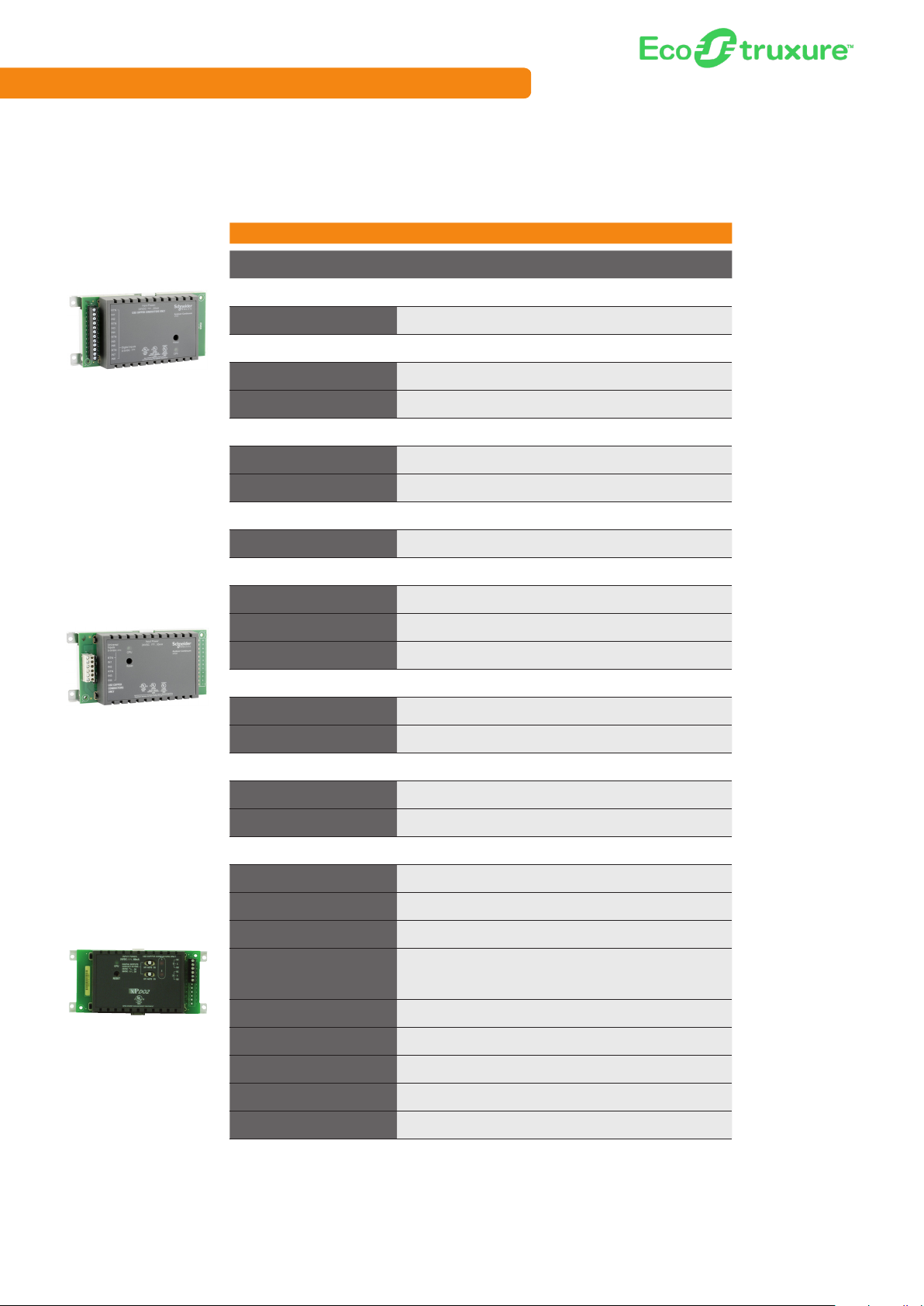
b3 Series
b3 Series xP Expansion I/O Modules
Part Number xPDI8 xPUI4
Communications
Protocol xP Bus x P Bus
Physical
xPDI8
8 Channel Digital Out put
Expansion Module
Dimensions
Weight (including baseplate) 0.22 kg (0. 48 lb.) 0.22 kg (0.48 lb.)
Power
Power
Consumption 25 mA 5 0 mA
Environmental
Operating Range
External Features
Enclosure rating
HOA Switches (DO/AO) No No
180 W x 82 H x 41 D mm
(7.10 W x 3.21 H x 1.60 D in.)
From xP bus w ith 400 mA power
supply
0 °C to 49 °C (32 °F to 120 °F) 1095% RH (non-condensing)
UL94 5 VB, IP 10 (<50 mm
pro tect ion)
180 W x 82 H x 41 D mm
(7.10 W x 3.21 H x 1.60 D in.)
From xP bus w ith 400 mA power
supply
0 °C to 49 °C (32 °F to 120 °F) 1095% RH (non-condensing)
UL94 5 VB, IP 10 (<50 mm
pro tect ion)
xPUI4
4 Channel Universal Input
Expansion Module
xPDO2
2 Channel Digital Out put
Expansion Module
Digital Status LEDs Yes Ye s
Terminals
I/O Terminals Two-piece terminal Two-piece terminal
I/O Expansion N/A N /A
External Enclosure/Mounting
Enclosure class
Mounting Wall mount Wall mount
Certifications
BTL No No
FCC 47 CFR § 15, Class A (Emission) 47 CFR § 15, Class A (Emission)
Industry Canada (IC) ICES-003 (Emission) ICES-003 (Emission)
UL
C-UL US Ye s Ye s
CE - EU Ye s Ye s
WEEE - Directive of the
European Union
RoHS Directive Yes Ye s
Open class (separate enclosure
required)
UL-916 (Energy Management
Equipment), UL-86 4 (Smoke
Control System Equipment) UUKL
Yes Ye s
Open class (separate enclosure
required)
UL-916 (Energy Management
Equipment), Optional UL864 (Smoke Control S ystem
Equipment) UUKL
RCM Yes Yes
B9

Schneider Electric EcoStruxure Building
b3 Series
b3 Series xP Expansion I/O Modules, continued
Part Number xPDO4 xPAO2 xPAO4
Communications
Protocol xP Bus xP Bus xP Bus
Physical
180 W x 82 H x 41 D mm
(7.10 W x 3.21 H x 1.60 D in.)
From xP bus w ith 400 mA
power supply
0 °C to 49 °C (32 °F to 120 °F)
10-95% RH (non-condensing)
UL94 5 VB, IP 10 (<50 mm
pro tect ion)
xPDO4
4 Channel Digital Out put
Expansion Module
Dimensions
Weight (including baseplate) 0.22 kg (0. 48 lb.) 0.22 kg (0.48 lb.) 0.22 kg (0.48 lb.)
Power
Power
Consumption 100 mA 80 mA 120 mA
Environmental
Operating Range
External Features
Enclosure rating
HOA Switches (DO/AO) Yes - (4/0) Yes - (0/2) Yes - (0/4)
180 W x 82 H x 41 D mm
(7.10 W x 3.21 H x 1.60 D in.)
From xP bus w ith 400 mA
power supply
0 °C to 49 °C (32 °F to 120 °F)
10-95% RH (non-condensing)
UL94 5 VB, IP 10 (<50 mm
pro tect ion)
180 W x 82 H x 41 D mm
(7.10 W x 3.21 H x 1.60 D in.)
From xP bus w ith 400 mA
power supply
0 °C to 49 °C (32 °F to 120 °F)
10-95% RH (non-condensing)
UL94 5 VB, IP 10 (<50 mm
pro tect ion)
xPAO 2
2 Channel Analog Out put
Expansion Module
xPAO 4
4 Channel Analog Out put
Expansion Module
Digital Status LEDs Yes Yes Yes
Terminals
I/O Terminals Two-piece terminal Two-piece terminal Two-piece terminal
I/O Expansion N/A N/A N/A
External Enclosure/Mounting
Enclosure class
Mounting Wall mount Wall mount Wall mount
Certifications
BTL No No No
FCC
Industry Canada (IC) ICES-003 (Emission) ICES-003 (Emission) ICES-003 (Emission)
UL
C-UL US Ye s Yes Yes
CE - EU Ye s Ye s Yes
WEEE - Directive of the
European Union
RoHS Directive Yes Yes Yes
Open class (separate
enclosure required)
47 CFR § 15, Class A
(Emission)
UL-916 (Energy Management
Equipment), UL-86 4 (Smoke
Control System Equipment)
UUKL
Yes Yes Yes
Open class (separate
enclosure required)
47 CFR § 15, Class A
(Emission)
UL-916 (Energy Management
Equipment)
Open class (separate
enclosure required)
47 CFR § 15, Class A
(Emission)
UL-916 (Energy Management
Equipment)
B10
RCM Yes Ye s Ye s

b3 Series
b3 Series Controllers - Inputs and Outputs
Part Number b3608 b3624 b3800 b3804 b3810 b3814
Universal Inputs 8 24 8 8 8 8
Digital Contact • • • • • •
Digit al Counter - Low Speed • • • • • •
Digital Counter - Medium Speed
Digit al Counter - High Speed
Digital Supervised • • • • • •
Analog Voltage - 0-1 V
Analog Voltage - 0-5 V • • • •
Analog Voltage - 0-10 V • •
Analog Voltage - 2-10 V
Analog Current - 0 -20 mA
Analog Current - 4 -20 mA • • • • • •
Analog Resistance
Analog Thermis tor - 10 k • • • • • •
Analog Thermis tor - 1.8 k
Analog Thermis tor - 1 k
Analog Inputs
Voltage - 0-5 V
Voltage - 0-10 V
Velocity Pressure
Analog Thermis tor - 10 k
Analog Thermis tor - 1.8 k
Analog Thermis tor - 1 k
Digital Outputs 8 4 8 4
Form A, SPST
Form C, SPDT • • • •
Tri ac
Analog Outputs 4 4
Voltage - 0-10 V • •
Current - 0-20 mA •
Damper Outputs
Form K, Triac
Voltage
Intelligent Sensors 1 1 1 1 1 1
Smar t Sensor (b3) • • • • • •
Schneider Electric EcoStruxure Solution
B11B11

Schneider Electric EcoStruxure Building
b3 Series
b3 Series Controllers - Inputs and Outputs, continued
Part Number b3850 b3 851 b3853 b3865-V b3866-V b3867
Universal Inputs 4 4 4 4 4 4
Digital Contact • • • • • •
Digit al Counter - Low Speed • • • • • •
Digital Counter - Medium Speed
Digit al Counter - High Speed
Digital Supervised • • • • • •
Analog Voltage - 0-1 V
Analog Voltage - 0-5 V • • • • • •
Analog Voltage - 0-10 V
Analog Voltage - 2-10 V
Analog Current - 0 -20 mA • • •
Analog Current - 4 -20 mA • • •
Analog Resistance
Analog Thermis tor - 10 k • • • • • •
Analog Thermis tor - 1.8 k
Analog Thermis tor - 1 k
Analog Inputs 1 2 1 1
Voltage - 0-5 V
Voltage - 0-10 V
Velocity Pressure internal internal internal inter nal
Analog Thermis tor - 10 k
Analog Thermis tor - 1.8 k
Analog Thermis tor - 1 k
Digital Outputs 4 4 4 3 3 5
Form A, SPST 3ch 3ch 3ch
Form C, SPDT
Tri ac 1ch 1c h 1ch • • •
Analog Outputs 2 2
Voltage - 0-10 V • •
Current - 0-20 mA
Damper Outputs 1 1
Form K, Triac internal
Voltage internal
Intelligent Sensors 1 1 1 1 1 1
Smar t Sensor (b3) • • • • • •
B12
B12

b3 Series
b3 Series Controllers - Inputs and Outputs, continued
Part Number b3885-V b3887
Universal Inputs 2 3 3 16
Digital Contact • • • •
Digit al Counter - Low Speed • • •
Digital Counter - Medium Speed
Digit al Counter - High Speed •
Digital Supervised • • • •
Analog Voltage - 0-1 V
Analog Voltage - 0-5 V • • •
Analog Voltage - 0-10 V •
Analog Voltage - 2-10 V
Analog Current - 0 -20 mA
Analog Current - 4 -20 mA • • • •
Analog Resistance
Analog Thermis tor - 10 k • • • •
Analog Thermis tor - 1.8 k
Analog Thermis tor - 1 k
Analog Inputs 1
Voltage - 0-5 V
Voltage - 0-10 V
Velocity Pressure internal
Analog Thermis tor - 10 k
Analog Thermis tor - 1.8 k
Analog Thermis tor - 1 k
Digital Outputs 2 5 5 8
Form A, SPST 1 channel 1 channel
Form C, SPDT •
Tri ac • 4 channel 4 channel
Analog Outputs 8
Voltage - 0-10 V •
Current - 0-20 mA •
Damper Outputs 1
Form K, Triac internal
Voltage
Intelligent Sensors 1 1 1 1
Smar t Sensor (b3) • • • •
b3887-L-115-C,
b3887-L-230-C
b3920,
b3920-D
B13

Schneider Electric EcoStruxure Building
b3 Series
b3 Series xP Expansion I/O Modules - Inputs and Outputs
Part Number xPDI8 xPUI4 xPDO4 xPAO2 xPAO4
Universal Inputs 4
Digital Contact •
Digit al Counter - Low Speed 3 channel
Digital Counter - Medium Speed
Digit al Counter - High Speed 1 channel
Digital Supervised •
Analog Voltage - 0-1 V
Analog Voltage - 0-5 V •
Analog Voltage - 0-10 V
Analog Voltage - 2-10 V
Analog Current - 0 -20 mA
Analog Current - 4 -20 mA •
Analog Resistance
Analog Thermis tor - 10 k •
Analog Thermis tor - 1.8 k
Analog Thermis tor - 1 k
Digital Inputs 8
Digital Contact •
Counte r - Low Speed
Counter - Medium Speed
Counte r - High Speed •
Digital Outputs 4
Form A, SPST
Form C, SPDT •
Tri ac
Analog Outputs 2 4
Voltage - 0-10 V • •
Current - 0-20 mA • •
The PCS enables offline engineering and project configuration
of EcoStruxure Building Operation without the need for live
equipment or for an engineer or technician to be onsite. Save time
and reduce costs by engineering automation servers and the
Enterprise Server offline and later deploying when live onsite.
Search keyword: Project Configuration Server
B14

MNB Series
Now native in EcoStruxure solution, the MNB series of MicroNet
controllers are designed in accordance with BACnet® standards.
When programmed or loaded with a pre-engineered application,
these controllers provide control for packaged rooftops, heat
pumps, fan coils, unit ventilators, and similar applications.
B15

MNB Series
MNB Series Controllers
MNB-1000
MNB-300
Part Number
Communications
Protocol BACnet Open Protocol BACnet Open Protocol BACnet Open Protocol
Communication Interface MS/TP, 960 0-76,80 0 bit/s MS /TP, 9600 -76,800 bi t/s MS/TP, 9600 -76,800 bit /s
Software
Preloaded Application/ASC No No No
Programability
Physical
Dimensions
Weight (including baseplate) 1.1 lb . 1.5 l b 3.95 lb.
Power
Power 20.4 to 30 VAC, 50/60 Hz 20.4 to 3 0 VAC, 50/60Hz 20.4 to 30 VAC, 50/60Hz
Consumption
Environmental
Operating Range
CPU Internals
CPU 8 Bit 8 Bit 32 Bit
Memory
Battery N /A N/A 72 hour
Real time clock N/A N/A
External Features
Enclosure rating
HOA Switches (DO/AO) No No No
Digital Status LEDs Yes Yes Yes
Display Via S -Link Sensor Via S-Link Sensor Via S-Link Sensor
I
ntelligent Sensors Senso r Link (S-Link) Sensor Link (S-Link) S ensor Link (S -Link)
Service Port MS/ TP jack on controller MS/ TP jack on co ntroller MS/TP jack on cont roller
Terminals
I/O Terminals Fixed terminal Fixed terminal Fixed terminal
I/O Expansion No No
A/D Conversion - Inputs 12- bit 12-b it 12-bi t
A/D Conversion - Outputs 8 -bit 8-bit 8-bit
External Enclosure/Mounting
Enclosure class N/A NEM A-1 N EMA -1
Conduit knockouts No Ye s Yes
Mounting Panel Mount Panel Mount Panel Mount
Certifications
BTL
FCC Part 15, Class A Par t 15, Class A Part 15, Class A
Industry Canda (IC)
UL
C-UL US
CE - EU 89/336/EEC, EN61326 89/336/EEC, EN61326 89/336/EEC, EN61326
WEEE - Directive of the Europe an Union
RoHS Directive RoH S II RoHS II RoHS II
RCM Yes Yes Yes
WorkPlace Tech programmable WorkPlace Tech programmable WorkPlace Tech programmable
127 W x 92 H x 41 D mm
(5 W x 3.625 H x 1.59 4 D in.)
15 VA (plus DO loads) 16VA 5 0VA
0°C to 55° C (32°F to 131°F)
5-95% RH (non-condensing)
"Flash: 256K
EEPROM: 4K"
NEMA-1, UL94 5 V (Plenum
rated)
BTL: BACnet Application
Specific Controller (B-ASC)
CAN/CSA 22.2, U LC/
ORD -C10 0-92, CANULC- S527
UL-916 (Energy Management
Equipment)
UL Listed to Canadian Safety
Standards (CAN/C SA 22.2).
2012/19/EU 2012/19/EU 2012/19/EU
MNB -70 MNB-300 MNB-1000
178 W x 100 H x 56 D mm
(7.0 W x 3.94 H x 2.19 D in.)
-40 °C to 60°C (- 40°F to 140°F)
5-95% RH (non-condensing)
"Flash: 256K
EEPROM: 4K"
N/A N/A
BTL: BACnet Application
Specific Controller (B-ASC)
CAN/CSA 22.2, U LC/
ORD-C100-92, CAN-ULC-S527
UL-916 (Energy Management
Equipment), UL-86 4 (Smoke
Control)
UL Listed to Canadian Safety
Standards (CAN/C SA 22.2).
213 W x 2 78 H x 58 D mm
(8.375 W x 10.937 H x 2. 281
D in .)
-40 °C to 60°C (- 40°F to 140°F)
5-95% RH (non-condensing)
"DDR: 64M
NOR Flash: 16M"
Yes
Up to 8 MNB -15s, each with 15
I/O points
BTL: BACnet Application
Specific Controller (B-ASC)
CAN/CSA 22.2, U LC/
ORD-C100-92, CAN-ULC-S527
UL-916 (Energy Management
Equipment), UL-86 4 (Smoke
Control)
UL Listed to Canadian Safety
Standards (CAN/C SA 22.2).
Schneider Electric EcoStruxure Solution
B16

MNB Series
MNB Series Controllers, continued
MNB -V1
MNB-V2
Part Number
Communications
Protocol Modbus BACnet Open Protocol BACnet Open Protocol
Communication Interface RS-485 MS/ TP, 960 0-76,80 0 bit/s MS/T P, 9600-76,800 bit/s
Software
Preloaded Application/ASC No No No
Programability
Physical
Dimensions
Weight (including baseplate) 1.5 l b. 2.68 lb. 2.65 lb.
Power
ower 20.4 to 3 0 VAC, 50/60H z 20.4 to 30 VAC, 50/6 0Hz 20.4 to 30 VAC, 50/60Hz
P
Consumption
Environmental
Operating Range
CPU Internals
CPU 8 Bit 8 Bit 8 Bit
Memory
Battery N/A N/A N/A
Real time clock
External Features
Enclosure rating N /A UL94 5 V (Plenum rate d) UL94 5V (Plenum rated)
HOA Switches (DO/AO) No No No
Digital Status LEDs Ye s Ye s Yes
Display No Via S-Link Sensor Via S-Link Sensor
Intelligent Sensors No Sensor Link (S-Link) Sensor Link (S-Link)
Service Port
Terminals
I/O Terminals
I/O Expansion
A/D Conversion - Inputs
A/D Conversion - Outputs
External Enclosure/Mounting
Enclosure class
Conduit knockouts
Mounting
Certifications
BTL
FCC
Industry Canada (IC)
UL
C-UL US
CE - EU
WEEE - Directive of the Europe an
Union
RoHS Directive
RCM
MNB -1000-15 MNB-V1-2 MNB-V2-2
Program resides on p arent
controller
178 W x 10 0 H x 56 D mm
(7.0 W x 3.94 H x 2.19 D in.)
16VA 15VA 15VA
-40 °C to 60°C (- 40°F to 140°F)
5-95% RH (non-condensing)
"Flash: 256K
EEPROM: 4K"
N/A N/A N/A
No MS/TP ja ck on controller MS/TP jack on cont roller
Fixed terminal Fixed terminal Fixed terminal
No No No
12-bit 12-bit 12-bit
8-bit N/A 8-bit
NE MA-1 N EMA-1 NE MA-1
Yes Ye s Ye s
Panel Mount Shaft mount Shaft mount
N/A
Part 15, Class A Part 15, Class A Part 15, Clas s A
CAN/CSA 22.2
UL-916 (Energy Management
Equipment)
UL Listed to Canadian Safety
Standards (CAN/C SA 22.2).
89/336/EEC, EN61326 89/336/EEC, EN61326 89/336/EEC, EN61326
2012/19/EU 2012/19/EU 2012/19/EU
RoHS II RoHS II RoHS II
Yes Ye s Ye s
WorkPlace Tech programmable WorkPlace Tech programmable
"159 W x 197 H x 63 D mm
(6.25 W x 7.75 H x 2.50 D in.)"
0°C to 55° C (32°F to 131°F)
5-95% RH (non-condensing)
"Flash: 256K
EEPROM: 4K"
BTL: BACnet Application
Specific Controller (B-ASC)
CAN/CSA 22.2, U LC/
ORD -C10 0-92, CANULC- S527
UL-916 (Energy Management
Equipment), UL-86 4 (Smoke
Control)
UL Listed to Canadian Safety
Standards (CAN/C SA 22.2).
"159 W x 197 H x 63 D mm
(6.25 W x 7.75 H x 2.50 D in.)"
0°C to 55° C (32°F to 131°F)
5-95% RH (non-condensing)
"Flash: 256K
EEPROM: 4K"
BTL: BACnet Application
Specific Controller
(B- ASC)
CAN/CSA 22.2, U LC/
ORD -C10 0-92, CANULC- S527
UL-916 (Energy Management
Equipment), UL-86 4 (Smoke
Control)
UL Listed to Canadian Safety
Standards (CAN/C SA 22.2).
Schneider Electric EcoStruxure Solution
B17B17

Schneider Electric EcoStruxure Building
MNB Series
MNB Series Controllers – Inputs and Outputs
Base Part Number MNB-70 MNB-300 MNB-1000 MNB-1000-15 MNB-V1-2 MNB-V2-2
Universal Inputs
Digital Contact
Digit al Counter - Low Speed
Digital Counter - Medium Speed
Digit al Counter - High Speed •
Digital Supervised
Analog Voltage - 0-1V
Analog Voltage - 0-5V
Analog Voltage - 0-10V
Analog Voltage - 2-10V
Analog Current - 0 -20mA • • • • • •
Analog Current - 4 -20mA
Analog Resistance
Analog Thermis tor - 10k
Analog Thermis tor - 1.8k
Analog Thermis tor - 1k
Digital Inputs
Digital Contact •
Counte r - Low Speed
Counter - Medium Speed
Counte r - High Speed
Analog Inputs
Voltage - 0-5V
Voltage - 0-10V
Velocity Pressure
Analog Thermis tor - 10k
Analog Thermis tor - 1.8k
Analog Thermis tor - 1k
Universal Outputs
Digital Contact
Digit al Counter - Low Speed
Digital Counter - Medium Speed
Digit al Counter - High Speed
Digital Supervised
Analog Voltage - 0-1V
Analog Voltage - 0-5V
Analog Voltage - 0-10V
Analog Voltage - 2-10V
Analog Current - 0 -20mA
Analog Current - 4 -20mA
Analog Resistance
Analog Thermis tor - 10k
Analog Thermis tor - 1.8k
Analog Thermis tor - 1k
Digital Outputs
Form A, SPST
Form C, SPDT
Tri ac
Analog Outputs
Voltage - 0-10V
Current - 0-20mA
Damper Outputs
Form K, Triac
Voltage
Intelligent Sensors
S-Link (MN-Sx for MNB)
3 6 12 6 3 3
• • • • • •
•
• • • • • •
• • • • • •
• • • • • •
• • • • • •
4
•
1 3 8 3 1
• • • •
• • • • •
• • • • •
3 6 8 6 3
• • • • •
1 1
internal internal
• • • • •
B18
B18

LonWorks Controllers
Schneider Electric EcoStruxure Solution
L1
L1

Schneider Electric EcoStruxure Building
Xenta Series
Xenta series controllers and I/O modules provide an
open and flexible system architecture and access to
standardized LonWorks-based network technology.
L2

Xenta Series
Xenta Series Controllers
Part Number
Communications
Protocol LonTalk communication protocol LonTalk communication protocol
Communication Interface TP/FT-10, 78 kbps TP/FT-10, 78 kbps
Software
Pre loaded Application/ASC Ye s Yes
Physical
Xent a 102-E S
VAV Zon e Cont roller
Xenta 102- AX
VAV Zon e Cont roller
Dimensions
Weight 0.4 kg (0.88 lb.) 1.04 kg (2.3 lb.)
Power
Power 24 VAC ±20%, 50/60 Hz 24 VAC ±10%, 50/ 60 Hz
Consumption
Environmental
Operating Range
External Features
Enclosure rating UL94 5 VB, IP 30 (<2.5 mm protection) NEM A-1, UL94 5VB, IP 10 (<50 mm protection)
HOA Switches (DO/AO) No No
Digital Status LEDs No No
Intelligent Sensors S TR150 STR150
Service Port Xenta OP Xenta OP
Terminals
I/O Terminals Fixed terminal Two-piece terminal
I/O Expansion No No
External Enclosure/Mounting
Enclosure class N/A N/A
Mounting D IN-rail or wall mount VAV/FP B box mo unt
Certifications
LonMark LonM ark certified: VAV 8010 LonMar k certified: VAV 8010
FCC 47 CFR § 15, Cla ss A (Emission) 47 CFR § 15, Class B (Emission)
UL UL-916 (Energy Management Equipment) UL-916 (Energy Management Equipment)
C-UL US Yes No
CE - EU Yes Ye s
WEEE - Directive of the Europe an
Union
RoHS Directive Ye s Yes
RCM Yes Ye s
102-ES 102-AX
007305370 007305401
127 W x 126 H x 50 D mm
(5.0 W x 4.9 H x 1.9 D in.)
6 VA with Xent a OP, Digital Outputs max 6
x 9 =114 VA ,
Total max 120 VA
0 °C to 50 °C (32 ° F to 122 °F) 0- 95% RH
(non-condensing)
Yes Ye s
159 W x 197 H x 63 D mm
(6.25 W x 7.75 H x 2.50 D in.)
9 VA, Digital Output s each 12 VA ,
Total max 36 VA
0 °C to 50 °C (32 ° F to 122 °F) 0- 90% RH
(non-condensing)
L3

Schneider Electric EcoStruxure Building
Xenta Series
Xenta Series Controllers, continued
Part Number
Communications
Protocol LonTalk communication protocol
Communication Interface TP/FT-10, 78 kbps
Software
Pre loaded Application/ASC Hybrid
Xenta 122-FC/24, 122-FC/230
Flexible Zone Controllers
Physical
Dimensions
Weight 0.3 kg (0.66 lb.) / 0.6 kg (1.3 lb)
Power
Power
Consumption
Environmental
Operating Range
External Features
Enclosure rating UL94 5VB, IP 20 (<12.5 mm protection)
HOA Switches (DO/AO) No
Digital Status LEDs No
Intelligent Sensors STR150
Service Port Xenta OP
Terminals
I/O Terminals Fixed terminal
I/O Expansion No
External Enclosure/Mounting
Enclosure class N/A
Mounting DIN-rail or wall mount
Certifications
LonMark
FCC 47 CFR Part 15, Subpart B, Class B
UL UL-916 (Energy Management Equipment)
C-UL US Ye s
CE - EU Ye s
WEEE - Directive of the Europe an
Union
RoHS Directive Yes
RCM Yes
122-FC/24,
122-FC/230
007307110,
007307120
112 W x 110 H x 50 D mm
(4.37 W x 4.29 H x 2.00 D in.)
24 VAC ±20%, 50/60 Hz
(230 V AC ±10%, 50 –60 H z)
Controller and OP 4 VA, including digital output s: FC/24: 84 VA,
FC/23 0: 20 VA
0 °C to 50 °C (32 ° F to 122 °F)
0-90% RH (non-condensing)
LonMar k certified: 8501 Fan Coil
Yes
L4

Xenta Series
Xenta Series Programmable Controllers, continued
281 282 283
Xenta 281
Freely Programmable
Controller
Xenta 282
Freely Programmable
Controller
Xenta 283
Freely Programmable
Controller
Part Number
Communications
Protocol LonTalk communication protocol LonTalk communication protocol LonTalk communication protocol
Communication Interface TP/FT-10, 78 kbps TP/FT-10, 78 kbps TP/ FT-10, 78 kbps
Software
Programmability Function Block Programmable Function Block Programmable Function Block Programmable
Physical
Dimensions
Weight (including baseplate) 1.18 kg (2.59 lb.) 1.18 kg (2.59 lb.) 1.18 kg (2.59 lb.)
Power
Power 24 VAC ±20%, 50/60 Hz 24 VAC ±2 0%, 50/60 Hz 24 VAC ±20%, 50/60 Hz
Consumption 10 VA 10 VA 10 VA
Environmental
Operating Range
CPU Internals
CPU Hitachi H8 32-bit Hitachi H8 32-bit Hitachi H8 32-bit
Memory
Battery 72 hour real time clock backup 72 hour real time clock backup 72 hour real time clock ba ckup
Real time clock ±12 minutes/year at 25 °C (77 °F) ±12 minutes /year at 25 °C ( 77 °F) ±12 minutes/ year at 25 °C (77 °F)
External Features
Enclosure rating
HOA Switches (DO/AO) No No No
Digital Status LEDs No No No
Service Port O P, RS-232 (9600 bps) O P, RS-232 (9600 bps) O P, RS-232 (9600 bps)
Terminals
I/O Terminals Terminal base Terminal base Terminal base
I/O Expansion No No No
External Enclosure/Mounting
Enclosure class
Mounting D IN-rail or wall mount DIN-rail or wall mount DIN-rail or wall mount
Certifications
LonMark
FCC 47 CFR § 15, Cla ss A (Emission) 47 CFR § 15, Class A (Emission) 47 CFR § 15, Class A (Emission)
UL
C-UL US Yes Yes Yes
CE - EU Yes Yes Yes
WEEE - Directive of the Europe an
Union
RoHS Directive Ye s Yes Yes
RCM Yes Ye s Yes
007300300 007300310 007300320
180 W x 110 H x 77.4 D mm
(7.1 W x 4.3 H x 3.1 D in.)
0 °C to 50 °C (32 ° F to 122 °F)
0-90% RH (non-condensing)
512 kB flash, 128 kB SR AM,
programs/data ma x 56 kB,
parameters 64 kB
UL94 5 VB, IP 20
(<12.5 mm protection)
Open class (separate enclosure
required)
LonMar k certified: Plant Controller
v3.0
UL-916 (Energy Management
Equipment), UL 3111-1 (Electrical
Measuring and Test Equipment)
Yes Yes Yes
180 W x 110 H x 77.4 D mm
(7.1 W x 4.3 H x 3.1 D in.)
0 °C to 50 °C (32 ° F to 122 °F)
0-90% RH (non-condensing)
512 kB flash, 128 kB SR AM,
programs/data ma x 56 kB,
parameters 64 kB
UL94 5 VB, IP 20
(<12.5 mm protection)
Open class (separate enclosure
required)
LonMar k certified: Plant Controller
v3.0
UL-916 (Energy Management
Equipment), UL 3111-1 (Electrical
Measuring and Test Equipment)
180 W x 110 H x 77.4 D mm
(7.1 W x 4.3 H x 3.1 D in.)
0 °C to 50 °C (32 ° F to 122 °F)
0-90% RH (non-condensing)
512 kB flash, 128 kB SR AM,
programs/data ma x 56 kB,
parameters 64 kB
UL94 5 VB, IP 20
(<12.5 mm protection)
Closed class
LonMar k certified: Real Time
Keeper v3.3
UL-916 (Energy Management
Equipment), UL 3111-1 (Electrical
Measuring and Test Equipment)
L5

Schneider Electric EcoStruxure Building
Xenta Series
Xenta Series Programmable Controllers, continued
301/N/P 301:C* 302/N/P 302:C*
Xenta 301/N/P
Freely Programmable
Controller
Xenta 301:C
Freely Programmable
Controller
Xenta 302/N/P
Freely Programmable
Controller
Xenta 30 2:C
Freely Programmable
Controller
Part Number
Communications
Protocol
Communication Interface TP/FT-10, 78 kbps TP/F T-10, 78 kbps TP/FT-10, 78 kbps TP/FT-10, 78 kbps
Software
Programmability
Physical
Dimensions
Weight (including baseplate) 1.18 kg (2.59 lb.) 1.18 kg (2.59 lb.) 1.18 kg (2.59 lb.) 1.18 kg (2.59 lb.)
Power
Power 24 VAC ±20%, 50/60 Hz 24 VAC ±20%, 50/60 Hz 24 VAC ±20 %, 50/60 Hz 24 VAC ±20 %, 50/60 Hz
Consumption 10 VA 10 VA 10 VA 10 VA
Environmental
Operating Range
CPU Internals
CPU Hitachi H8 32-bit Hitachi H8 32-bit Hitachi H8 32-bit Hitachi H8 32-bit
Memory
Battery
Real time clock
External Features
Enclosure rating
HOA Switches (DO/AO) No No No No
Digital Status LEDs No No No No
Service Port O P, RS-232 (9600 bps) OP, RS-232 (9600 bps) OP, RS-232 (9 600 bps) OP, RS-232 (96 00 bps)
Terminals
I/O Terminals Terminal base Terminal base Terminal base Terminal base
I/O Expansion
External Enclosure/Mounting
Enclosure class
Mounting D IN-rail or wall mount DIN -rail or wall mount DIN- rail or wall mount DIN-rail or wall mount
Certifications
LonMark
FCC
UL
C-UL US Yes Ye s Ye s Ye s
CE - EU Yes Ye s Ye s Ye s
WEEE - Directive of the Europe an
Union
RoHS Directive Ye s Ye s Ye s Ye s
RCM Yes Yes Ye s Ye s
007300092 007300017 007300112 007300018
LonTalk communication
protocol
Function B lock
Programmable
180 W x 110 H x 77.4
D mm
(7.1 W x 4.3 H x 3.1 D in.)
0 °C to 50 °C (32 ° F to 122 °F )
0-90% RH (non-condensing)
512 kB flash, 128 kB
SRAM, programs/data
max 56 k B, parameters
64 kB
72 hour real time clock
backup
±12 minutes/ye ar at
25 °C (77 ° F)
UL94 V- 0, IP 20
(<12.5 mm protection)
Up to 2 Xenta 4 00 series
I/O modules
Open class (separate
enclosure required)
LonMark certified: Plant
Controller v3.0
47 CFR § 15, Class B
(Emission)
UL-916 (Energy
Management Equipment)
Yes Yes Yes Yes
LonTalk communication
protocol
Function B lock
Programmable
180 W x 110 H x 77.4
D mm
(7.1 W x 4.3 H x 3.1 D in.)
0 °C to 50 °C (32 ° F to 122 °F )
0-90% RH (non-condensing)
512 kB flash, 128 kB
SRAM, programs/data
max 56 k B, parameters
64 kB
72 hour real time clock
backup
±12 minutes/ye ar at
25 °C (77 ° F)
UL94 V- 0, IP 20
(<12.5 mm protection)
Up to 4 Xenta 4 00 series
I/O modules
Open class (separate
enclosure required)
LonMark certified: Plant
Controller v3.0
47 CFR § 15, Class B
(Emission)
UL-916 (Energy
Management Equipment)
LonTalk communication
protocol
Function B lock
Programmable
180 W x 110 H x 77.4
D mm
(7.1 W x 4.3 H x 3.1 D in.)
0 °C to 50 °C (32 ° F to 122 °F )
0-90% RH (non-condensing)
512 kB flash, 128 kB
SRAM, programs/data
max 56 k B, parameters
64 kB
72 hour real time clock
backup
±12 minutes/ye ar at
25 °C (77 ° F)
UL94 V- 0, IP 20
(<12.5 mm protection)
Up to 2 Xenta 4 00 series
I/O modules
Open class (separate
enclosure required)
LonMark certified: Plant
Controller v3.0
47 CFR § 15, Class B
(Emission)
UL-916 (Energy
Management Equipment)
LonTalk communication
protocol
Function B lock
Programmable
180 W x 110 H x 77.4
D mm
(7.1 W x 4.3 H x 3.1 D in.)
0 °C to 50 °C (32 ° F to 122 °F )
0-90% RH (non-condensing)
512 kB flash, 128 kB
SRAM, programs/data
max 56 k B, parameters
64 kB
72 hour real time clock
backup
±12 minutes/ye ar at
25 °C (77 ° F)
UL94 V- 0, IP 20
(<12.5 mm protection)
Up to 4 Xenta 4 00 series
I/O modules
Open class (separate
enclosure required)
LonMark certified: Plant
Controller v3.0
47 CFR § 15, Class B
(Emission)
UL-916 (Energy
Management Equipment)
L6
* 301C, 302C, 401B, 401C are not available in all markets. Check with your local Schneider Electric office.

Xenta Series
Xenta Series Programmable Controllers, continued
401 401: B* 401:C*
Xenta 401
Freely Programmable
Controller
Xenta 401:B
Data Manager
Xen ta 4 01:C
Freely Programmable
Controller
Part Number
Communications
Protocol LonTalk communication protocol LonTalk communication protocol LonTalk communication protocol
Communication Interface TP/FT-10, 78 kbps TP/FT-10, 78 kbps T P/FT-10, 78 kbps
Software
Programmability Function Block Programmable Function Block Programmable Function Block Programmable
Physical
Dimensions
Weight (including baseplate) 0.595 kg (1.41 lb.) 0.595 kg (1.41 lb.) 0. 595 kg (1.41 lb.)
Power
Power 24 VAC ±20%, 50/60 Hz 24 VAC ±20%, 50/6 0 Hz 24 VAC ±20%, 50/60 Hz
Consumption 2 VA 2 VA 2 VA
Environmental
Operating Range
CPU Internals
CPU Hitachi H8 32-bit Hitachi H8 32-bit Hitachi H8 32-bit
Memory 2 MB flash, 128 kB SRA M
Battery 72 hour real time clock backup 72 hour real time clock backup 72 hour r eal time clock backup
Real time clock ±12 minutes/year at 25 °C (77 °F) ±12 minutes/year at 25 °C (77 °F) ±12 minutes/year at 25 °C (7 7 °F)
External Features
Enclosure rating
HOA Switches (DO/AO) No No No
Digital Status LEDs No No No
Service Port O P, RS-232 (9600 bps) O P, RS-232 (9600 bps) O P, RS-232 (9600 bps)
Terminals
I/O Terminals Terminal base Terminal base Terminal base
I/O Expansion
External Enclosure/Mounting
Enclosure class
Mounting D IN-rail or wall mount DIN -rail or wall mount DIN- rail or wall mount
Certifications
LonMark
FCC 47 CFR § 15, Cla ss B (Emission) 47 CFR § 15, Class A (Emission) 47 CFR § 15, Clas s B (Emission)
UL
C-UL US Yes Yes Yes
CE - EU Yes Yes Yes
WEEE - Directive of the Europe an
Union
RoHS Directive Ye s Yes Yes
RCM Yes Ye s Ye s
007301012 007301030 007300104
90 W x 110 H x 77.4 D m m
(3.55 W x 4.3 3 H x 3.05 D in.)
0 °C to 50 °C (32 ° F to 122 °F)
0-90% RH (non-condensing)
UL94 V- 0, IP 20
(<12.5 mm protection)
Up to 10 Xenta 400 series I /O
modules
Open class (separate enclosure
required)
LonMark certified: Plant Controller
v3.0
UL-916 (Energy Management
Equipment)
Yes Yes Yes
90 W x 110 H x 7 7.4 D mm
(3.55 W x 4.3 3 H x 3.05 D in.)
0 °C to 50 °C (32 ° F to 122 °F)
0-90% RH (non-condensing)
2 MB flash, 128 kB SRAM, 234
kB programs/data, 234 kB
parameters
UL94 V- 0, IP 20
(<12.5 mm protection)
No
Open class (separate enclosure
required)
LonMark certified: Plant Controller
v3.0
UL-916 (Energy Management
Equipment)
90 W x 110 H x 77.4 D m m
(3.55 W x 4.3 3 H x 3.05 D in.)
0 °C to 50 °C (32 ° F to 122 °F)
0-90% RH (non-condensing)
2 MB flash, 128 kB SRAM
UL94 V- 0, IP 20
(<12.5 mm protection)
Up to 15 Xenta 40 0 series I /O
modules
Open class (separate enclosure
required)
LonMark certified: Plant Controller
v3.0
UL-916 (Energy Management
Equipment)
* 301C, 302C, 401B, 401C are not available in all markets. Check with your local Schneider Electric office.
L7

Schneider Electric EcoStruxure Building
Xenta Series
Xenta Series I/O Modules
Xenta 411/412
10 Channel Digital Input
Modules
Xenta 421A /422A
4 Channel Universal Input/5
Channel Digital Output
Modules
411,
412
Part Number
Communications
Protocol LonTalk communication protocol LonTalk communication protocol
Communication Interface TP/FT-10, 78 kbps TP/FT-10, 78 kbps
Physical
Dimensions
Weight (including baseplate)
Power
Power
Consumption
Environmental
Operating Range
External Features
Enclosure rating
HOA Switches (DO/AO)
Digital Status LEDs
Terminals
I/O Terminals
External Enclosure/Mounting
Enclosure class
Mounting
Certifications
LonMark No
FCC
UL
C-UL US Yes Yes
CE - EU Yes Yes
WEEE - Directive of the Europe an
Union
RoHS Directive Ye s Yes
RCM
90 W x 110 H x 75 D mm
(3.55 W x 4.3 3 H x 3.1 D in.)
0.595 kg (1.41 lb.) 0.295 kg (0.65 lb.)
24 VAC ±20%, 50/60 Hz 24 VAC ±20%, 50/60 Hz
2 VA 4 W, 8 VA transformer
0 °C to 50 °C (32 ° F to 122 °F)
0-90% RH (non-condensing)
UL94 V- 0, IP 20
(<12.5 mm protection)
Available on 412 model Available on 422A model
Available on 412 model Available on 422A model
Terminal base Terminal base
Enclosed class (no separate
enclosure required)
DIN- rail or wall mount DIN-rail or wall mount
47 CFR § 15, Class A (Emission) 47 CFR § 15, Class B (Emission)
UL-916 (Energy Management
Equipment), UL 3111-1 (Electrical
Measuring and Test Equipment)
Yes Ye s
Yes Yes
0073 02 011,
007302031
90 W x 110 H x 75 D mm
(3.55 W x 4.3 3 H x 3.1 D in.)
0 °C to 50 °C (32 ° F to 122 °F)
0-90% RH (non-condensing)
UL94 V- 0, IP 20
(<12.5 mm protection)
Open class (separate enclosure
required)
LonMar k® cert ified: Digital Input
2054 3, Analog Input 0520
UL-916 (Energy Management
Equipment)
421A,
422A
007302450,
007302460
L8

Xenta Series
Xenta Series I/O Modules, continued
Xenta 451A / 452 A
8 Channel Universal Input/2
Channel Analog Output
Modules
Xen ta 471
8 Channel Universal Input
Module
451A ,
452A
Part Number
Communications
Protocol LonTalk communication protocol LonTalk communication protocol LonTalk communication protocol
Communication Interface TP/FT-10, 78 kbps TP/ FT-10, 78 kbps TP/FT-10, 78 kbps
Physical
Dimensions
Weight (including baseplate)
Power
Power
Consumption
Environmental
Operating Range
External Features
Enclosure rating
HOA Switches (DO/AO)
Digital Status LEDs
Terminals
I/O Terminals
External Enclosure/Mounting
Enclosure class
Mounting
Certifications
LonMark
FCC
UL
C-UL US Yes Yes Yes
CE - EU
WEEE - Directive of the Europe an
Union
RoHS Directive Ye s Yes Yes
RCM Yes Ye s Ye s
007302850,
007302860
90 W x 110 H x 75 D mm
(3.55 W x 4.3 3 H x 3.1 D in.)
0.295 kg (0.65 lb.) 0.495 kg (1.09 lb.) 0.4 95 kg (1.09 lb.)
24 VAC ±20%, 50/60 Hz 24 VAC ±20%, 50/60 Hz 24 VAC ±20%, 50 /60 Hz
3 W, 6 VA transfor mer 4 W, 8 VA transformer 3 W, 6 VA transformer
0 °C to 50 °C (32 ° F to 122 °F)
0-90% RH (non-condensing)
UL94 V- 0, IP 20
(<12.5 mm protection)
Available on 452A model No Available on 492 mod el
Available on 452A model No Available on 492 mod el
Terminal base Terminal base Terminal base
Enclosed class (no separate
enclosure required)
DIN- rail or wall mount DIN -rail or wall mount DIN-rail or wall mount
LonMar k certified: Analog Input
0520, Analog Output 0521
47 CFR § 15, Class B
(Emission)
UL-916 (Energy Management
Equipment)
Yes Yes Yes
Yes Yes Yes
90 W x 110 H x 75 D mm
(3.55 W x 4.3 3 H x 3.1 D in.)
0 °C to 50 °C (32 ° F to 122 °F)
0-90% RH (non-condensing)
UL94 V- 0, IP 20
(<12.5 mm protection)
Enclosed class (no separate
enclosure required)
No No
47 CFR § 15, Class A
(Emission)
UL-916 (Energy Management
Equipment), UL 3111-1 (Electrical
Measuring and Test Equipment)
471
007302910
90 W x 110 H x 75 D mm
(3.55 W x 4.3 3 H x 3.1 D in.)
0 °C to 50 °C (32 ° F to 122 °F)
0-90% RH (non-condensing)
UL94 V- 0, IP 20
(<12.5 mm protection)
Enclosed class (no separate
enclosure required)
47 CFR § 15, Class A
(Emission)
UL-916 (Energy Management
Equipment), UL 3111-1 (Electrical
Measuring and Test Equipment)
491,
492
007303010,
007303030
Xenta 491/492
8 Channel
Analog Output
Modules
L9

Schneider Electric EcoStruxure Building
Xenta Series
Xenta Series Controllers - Inputs and Outputs
102-B 102-EF 102-VF 102- ES 102-AX
Part Number 007305310 007305330 007305350 007305370 007305401
Universal Inputs 4
Digital Contact •
Digit al Counter - Low Speed
Digital Counter - Medium Speed
Digit al Counter - High Speed
Digital Supervised
Analog Voltage - 0-1 V
Analog Voltage - 0-5 V •
Analog Voltage - 0-10 V
Analog Voltage - 2-10 V
Analog Current - 0 -20 mA
Analog Current - 4 -20 mA
Analog Resistance
Analog Thermis tor - 10 k •
Analog Thermis tor - 1.8 k
Analog Thermis tor - 1 k
Digital Inputs 2 2 2 2
Digital Contact • • • •
Counte r - Low Speed
Counter - Medium Speed
Counte r - High Speed
Analog Inputs 2 2 2 3 5
Voltage - 0-5 V 4 channel
Voltage - 0-10 V • • • 1 channel
Velocity Pressure • • • 1 channel internal 1 cha nnel internal
Analog Thermis tor - 10 k
Analog Thermis tor - 1.8 k •
Analog Thermis tor - 1 k
Digital Outputs 2 1 6 3
Form A, SPST
Form C, SPDT 1 channel
Tri ac 2 channel • • •
Analog Outputs 1 1 2 1
Voltage - 0-10 V • • • •
Current - 0-20 mA
Damper Outputs 1
Form K, Triac internal
Voltage
Intelligent Sensors 1 1 1 1 1
STR (Xenta) • • • • •
L10

Xenta Series
Xenta Series Controllers - Inputs and Outputs, continued
103-A 104 -A
Part Number 007305610 007305910
Universal Inputs 4
Digital Contact •
Digit al Counter - Low Speed
Digital Counter - Medium Speed
Digit al Counter - High Speed
Digital Supervised
Analog Voltage - 0-1 V
Analog Voltage - 0-5 V
Analog Voltage - 0-10 V •
Analog Voltage - 2-10 V
Analog Current - 0 -20 mA
Analog Current - 4 -20 mA
Analog Resistance
Analog Thermis tor - 10 k
Analog Thermis tor - 1.8 k •
Analog Thermis tor - 1 k
Digital Inputs 2 2 3 3
Digital Contact • • • •
Counte r - Low Speed
Counter - Medium Speed
Counte r - High Speed
Analog Inputs 1 1 1 •
Voltage - 0-5 V
Voltage - 0-10 V •
Velocity Pressure
Resistor, 10 k •
Analog Thermis tor - 10 k
Analog Thermis tor - 1.8 k • •
Analog Thermis tor - 1 k
Digital Outputs 2 5 4 8
Form A, SPST 1 channel 4
Form C, SPDT
Tri ac • 4 channel • 4
Analog Outputs 2 1 3
Voltage - 0-10 V • • •
Current - 0-20 mA
Damper Outputs
Form K, Triac
Voltage
Intelligent Sensors 1 1 1 1
STR (Xenta) • • • •
110 - D/ 24,
110 - D/ 230
007306010,
007306030
122- FC/ 24,
122- FC/ 230
007307110,
007307120
L11

Schneider Electric EcoStruxure Building
Xenta Series
Xenta Series Programmable Controllers - Inputs and Outputs
281 282 283 301/N/P 301:C 302/N/P 302:C
Part Number 007300300 007300310 007300320 007300092 007300017 007300112 007300018
Universal Inputs 4 4 4 4 4 4
Digital Contact • • • • • •
Digit al Counter - Low Speed
Digital Counter - Medium Speed
Digit al Counter - High Speed
Digital Supervised
Analog Voltage - 0-1 V • • • • • •
Analog Voltage - 0-5 V • • • • • •
Analog Voltage - 0-10 V • • • • • •
Analog Voltage - 2-10 V • • • • • •
Analog Current - 0 -20 mA
Analog Current - 4 -20 mA
Analog Resistance
Analog Thermis tor - 10 k
Analog Thermis tor - 1.8 k • • • • • •
Analog Thermis tor - 1 k
Digital Inputs 2 2 2 4 4 4 4
Digital Contact • • • • • • •
Counte r - Low Speed
Counter - Medium Speed • • •
Counte r - High Speed
Analog Inputs 4 2 4 4 4 4 4
Voltage - 0-5 V
Voltage - 0-10 V •
Velocity Pressure
Analog Thermis tor - 10 k •
Analog Thermis tor - 1.8 k • • • • • •
Analog Thermis tor - 1 k
Digital Outputs 3 4 6 6 6 4 4
Form A, SPST • • • • • •
Form C, SPDT
Tri ac
Analog Outputs 3 4 2 2 4 4
Voltage - 0-10 V • • • • • •
Current - 0-20 mA
•
L12

Xenta Series
Xenta Series I/O Modules - Inputs and Outputs
411,
412
Part Number
Universal Inputs 4 8 8
Digital Contact • •
Digital Counter - Low Speed •
Digital Counter - Medium Speed •
Digital Counter - High Speed
Digital Supervised
Analog Voltage - 0-1 V • • •
Analog Voltage - 0-5 V • • •
Analog Voltage - 0-10 V • • •
Analog Voltage - 2-10 V • • •
Analog Current - 0-20 mA • • •
Analog Current - 4-20 mA • • •
Analog Resistance • •
Analog Thermistor - 10 k • •
Analog Thermistor - 1.8 k • •
Analog Thermistor - 1 k
Digital Inputs 10
Digital Contact •
Counter - Low Speed
Counter - Medium Speed •
Counter - High Speed
Digital Outputs 5
Form A, SPST •
Form C, SPDT
Triac
Analog Outputs 2 8
Voltage - 0-10 V • •
Current - 0-20 mA
007302011,
007302031
421A,
422A
007302450,
007302460
451A,
452A
007302850,
007302860
471
007302910
491,
492
007303010,
007303030
Note: 421A, 422 A, 451A, and 452A can also be used as distributed I/Os under an automation server.
L13

Schneider Electric EcoStruxure Building
MNL Series
The MNL series of controllers are designed in accordance
with LonMark® guidelines. When programmed or loaded
with a pre-engineered application, these controllers provide
control for packaged rooftops, heat pumps, fan coils, unit
ventilators, and similar applications.
L14

MNL Series
MNL Series Controllers
Part Number
Communications
Protocol
Communication Interface TP/F T-10, 78 kbps TP/FT-10, 78 kbps TP/FT-10, 78 kbps
Software
Pre loaded Application/ASC Yes Yes Yes
MNL-50
Fan Coil, Heat Pump, Roof
Top, Satellite Zone Controllers
MNL-100
MNL-100
Fan Coil, Heat Pump, Roof
Top, Satellite Zone Controllers
MNL-100
MNL-110
Fan Coil Zone Controller
Programmability WorkPlace Tech programmable WorkPlace Tech programmable WorkPlace Tech programmable
Physical
Dimensions
Weight (including baseplate) N/A N/A N/A
Power
Power 24 VAC +25% -15%, 50/60 Hz 24 VAC +25% -15%, 50/60 Hz 24 VAC +25% -15%, 50/60 Hz
Consumption
Environmental
Operating Range
CPU Internals
CPU Neuron FT5000 Neuron FT5000 Neuron FT5000
Memory
Battery N/A N /A N/A
Real time clock No No No
External Features
Enclosure rating
HOA Switches (DO/AO) No No No
Digital Status LEDs No No No
Display Via S-Link Sensor V ia S-Link Sensor Via S-Link Sensor
Intelligent Sensors Sensor Link (S-Link) Sensor Link (S-Link) Sensor Link (S-Link)
Service Port
Terminals
I/O Terminals Fixed terminal Terminal base Fixed terminal
I/O Expansion No No No
A/D Conversion - Inputs Yes Ye s Ye s
A/D Conversion - Outputs Ye s Ye s Yes
External Enclosure/Mounting
Enclosure class
Conduit knockouts No No No
Mounting Wall mount DIN-r ail or wall mount DIN- rail or wall mount
Certifications
LonMark
FCC
Industry Canada (IC) Yes Ye s Ye s
UL
C-UL US Ye s Yes Yes
CE - EU Ye s Ye s Yes
WEEE - Directive of the
European Union
RoHS Directive No No No
RCM Yes Ye s Ye s
MNL- 50 MNL-100 MN L-110
MNL-5RF3, MNL-5RH3,
MNL-5RR3, MNL-5RS3,
MNL-5RS4
®
Lo nTalk
communication
protocol
127 W x 112 H x 41 D mm
(5.0 W x 4.5 H x 1.625 D in.)
12 VA (84 VA with DO loads
@24 VA each)
-40 °C to 60 °C (-40 ° F to 140
°F) 5 -95% RH (non -condensing)
Flash = 64 byte or 512 k bit,
EEProm 6 k bit or 8 k byte
NEMA-1, UL94 5 V (Plenum
rated)
LonWorks Network Jack via
S-Link Sensor
N/A N/A N/A
LonMar k certified: Fan Coil
8020, H eat Pump, Roof Top,
Satellite
47 CFR § 15, Class B
(Emission)
UL-916 (Energy Management
Equipment)
No No No
MNL-10RF3, MNL-
10RH3, MNL-10RR3,
MNL-10RS3, MNL-10RS4
LonTalk communication
protocol
109 W x 111 H x 51 D mm
(4.37 W x 4.29 H x 2.00 D in.)
15 VA 20.5 VA
-40 °C to 60 °C (-40 ° F to 140
°F) 5 -95% RH (non -condensing)
Flash = 64 byte or 512 k bit,
EEProm 6 k bit or 8 k byte
NEMA-1, UL94 5 V (Plenum
rated)
LonWorks Network Jack
LonMar k certified: Fan Coil
8020, H eat Pump, Roof Top,
Satellite
47 CFR § 15, Class B
(Emission)
UL-916 (Energy Management
Equipment)
LonTalk communication
protocol
154.9 W x 107 H x 50 D mm
(6.1 W x 4.2 H x 2.0 D in.)
-40 °C to 55 °C (-40 ° F to 131
°F) 0 -95% RH (non -condensing)
Flash = 64 byte or 512 k bit,
EEProm 6 k bit or 8 k byte
UL94 V- 0
LonWorks Network Jack via
S-Link Sensor
LonMar k certified: Fan Coil
8020
47 CFR § 15, Class B
(Emission)
UL-873 (Temperature Indicat ing
and Regulating Equipment)
Recognized component and
UL-916 (Energy Management
Equipment) Recognized
MN L-11RF3
L15

Schneider Electric EcoStruxure Building
MNL Series
MNL Series Controllers, continued
Part Number MNL-13RF3
Communications
Protocol
Communication Interface TP/F T-10, 78 kbps TP/FT-10, 78 kbps TP/FT-10, 78 kbps
Software
Pre loaded Application/ASC Yes Yes Yes
Programmability WorkPlace Tech programmable WorkPlace Tech programmable WorkPlace Tech programmable
Physical
MNL-130
Fan Coil Zone Controller
MNL-150
Fan Coil, Heat Pump, Roof
Top, Satellite Zone Controllers
MNL-200
Fan Coil, Heat Pump, Roof
Top, Satellite Zone Controllers
L16
Dimensions
Weight (including baseplate) N/A N/A N/A
Power
Power 24 VAC +25% -15%, 50/60 Hz 24 VAC +25% -15%, 50/60 Hz 24 VAC +25% -15%, 50/60 Hz
Consumption 21.5 VA 15 VA 15 VA
Environmental
Operating Range
CPU Internals
CPU Neuron FT5000 Neuron FT5000 Neuron FT5000
Memory
Battery N/A N /A N/A
Real time clock No No No
External Features
Enclosure rating U L94 V-0
HOA Switches (DO/AO) No No No
Digital Status LEDs No No No
Display Via S-Link Sensor V ia S-Link Sensor Via S-Link Sensor
Intelligent Sensors Sensor Link (S-Link) Sensor Link (S-Link) Sensor Link (S-Link)
Service Port
Terminals
I/O Terminals Fixed terminal Terminal base Terminal base
I/O Expansion No No No
A/D Conversion - Inputs Yes Ye s Ye s
A/D Conversion - Outputs Ye s Ye s Yes
External Enclosure/Mounting
Enclosure class N/A N/A N/A
Conduit knockouts No No No
Mounting DI N-rail or wall mount DIN-rail or wall mount DIN- rail or wall mo unt
Certifications
LonMark
FCC
Industry Canada (IC) Yes Ye s Ye s
UL
C-UL US Ye s Yes Yes
CE - EU Ye s Ye s Yes
WEEE - Directive of the
European Union
RoHS Directive No No No
RCM Yes Ye s Ye s
MNL-130 MNL-150 MNL-20 0
MNL-15RF3, MNL-15RH3,
MNL-15RR3, MNL-15RS3,
MNL-15RS 4
LonTalk communication protocol LonTalk communication protocol LonTalk communication protocol
154.9 W x 107 H x 50 D mm
(6.1 W x 4.2 H x 2.0 D in.)
-40 °C to 55 °C (-40 ° F to 131
°F) 0 -95% RH (non -condensing)
Flash = 64 byte or 512 k bit,
EEProm 6 k bit or 8 k byte
LonWorks Network Jack via
S-Link Sensor
LonMar k certified: Fan Coil
8020
47 CFR § 15, Class B
(Emission)
UL-873 (Temperature
Indicating and Regulating
Equipment) Recognized
compon ent and UL-916
(Energy Management
Equipment) Recognized
No No No
109 W x 111 H x 51 D mm
(4.37 W x 4.29 H x 2.00 D in.)
-40 °C to 60 °C (-40 ° F to 140
°F) 5 -95% RH (non -condensing)
Flash = 64 byte or 512 k bit,
EEProm 6 k bit or 8 k byte
NEMA-1, UL94 5 V (Plenum
rated)
LonWorks Network Jack LonWorks Network Jack
LonMar k certified: Fan Coil
8020, H eat Pump, Roof Top,
Satellite
47 CFR § 15, Class B
(Emission)
UL-916 (Energy Management
Equipment)
MNL-20RF3, MNL-20RH3,
MNL-20RR3, MNL-
20RS3, MNL-20RS4
109 W x 111 H x 51 D mm
(4.37 W x 4.29 H x 2.00 D in.)
-40 °C to 60 °C (-40 ° F to 140
°F) 5 -95% RH (non -condensing)
Flash = 64 byte or 512 k bit,
EEProm 6 k bit or 8 k byte
NEMA-1, UL94 5 V (Plenum
rated)
LonMar k certified: Fan Coil
8020, H eat Pump, Roof Top,
Satellite
47 CFR § 15, Class B
(Emission)
UL-916 (Energy Management
Equipment)

MNL Series
MNL Series Controllers, continued
Part Number MNL-800-102 MNL-V1RV3-2 MNL-V2RV3-2
Communications
Protocol
Communication Interface TP/F T-10, 78 kbps TP/FT-10, 78 kbps TP/FT-10, 78 kbps
Software
Pre loaded Application/ASC Yes Yes Yes
Programmability WorkPlace Tech programmable WorkPlace Tech programmable WorkPlace Tech programmable
Physical
Dimensions
Weight (including baseplate) N/A N/A N/A
MNL-800
Local Controller
MNL-V1RVx
VAV Zon e Cont roller
MNL-V2RVx
VAV Zon e Cont roller
Power
Power 24 VAC +25% -15%, 50/60 Hz 24 VAC +25% -15%, 50/60 Hz 24 VAC +25% -15%, 50/60 Hz
Consumption 20 VA 12 VA
Environmental
Operating Range
CPU Internals
CPU
Memory
Battery
Real time clock
External Features
Enclosure rating N /A
HOA Switches (DO/AO) No No No
Digital Status LEDs No No No
Display Via S-Link Sensor V ia S-Link Sensor Via S-Link Sensor
Intelligent Sensors Sensor Link (S-Link) Sensor Link (S-Link) Sensor Link (S-Link)
Service Port LonWorks Network Jack
Terminals
I/O Terminals Terminal base Fixed terminal Fixed terminal
I/O Expansion No No No
A/D Conversion - Inputs Yes Ye s Ye s
A/D Conversion - Outputs Ye s Ye s Yes
External Enclosure/Mounting
Enclosure class
Conduit knockouts Yes - On encl osure No No
Mounting Wall mount Wall mount Wall mount
Certifications
LonMark LonMark cer tified LonMark certifi ed: VAV 8010 Lo nMark cer tified: VAV 8010
FCC
Industry Canada (IC) Yes Ye s Ye s
UL
C-UL US Ye s Yes Yes
CE - EU Ye s Ye s Yes
WEEE - Directive of the
European Union
RoHS Directive No No No
RCM Yes Ye s Ye s
MNL- 800 MNL-V1RVx MNL-V2RVx
LonTalk communication
protocol
216 W x 262 H x 101 D mm
(8.5 W x 10.875 H x 4.25 D in.)
-40 °C to 60 °C (-40 ° F to 140
°F) 5 -95% RH (non -condensing)
SAF- C161, 10 MHz Clock
speed, 16 bit word size
EPROM = 512; RAM = 128;
EEPROM = 32
Rechargeable, 3 days for clock
and RAM
±30 minutes/year at 25 °C
(77 °F )
Open class (separate
enclosure required)
47 CFR § 15, Class A
(Emission)
UL-916 (Energy Management
Equipment)
No No No
LonTalk communication
protocol
159 W x 197 H x 63 D mm
(6.25 W x 7.75 H x 2.50 D in.)
0 °C to 55 °C (32 ° F to 131 °F)
5-95% RH (non-condensing)
Neuron FT5000 Neuron FT5000
Flash = 64 byte or 512 k bit,
EEProm 6 k bit or 8 k byte
N/A N/A
No No
NEMA-1, UL94 5 V (Plenum
rated)
LonWorks Network Jack via
S-Link Sensor
N/A N/A
47 CFR § 15, Class B
(Emission)
UL-916 (Energy Management
Equipment)
LonTalk communication
protocol
159 W x 197 H x 63 D mm
(6.25 W x 7.75 H x 2.50 D in.)
12 VA (84 VA with DO loads
@24 VA each)
0 °C to 55 °C (32 ° F to 131 °F)
5-95% RH (non-condensing)
Flash = 64 byte or 512 k bit,
EEProm 6 k bit or 8 k byte
NEMA-1, UL94 5 V (Plenum
rated)
LonWorks Network Jack via
S-Link Sensor
47 CFR § 15, Class B
(Emission)
UL-916 (Energy Management
Equipment)
L17

Schneider Electric EcoStruxure Building
MNL Series
MNL Series Controllers, continued
Part Number MNL-V3RV3
Communications
Protocol LonTalk communication protocol
Communication Interface TP/F T-10, 78 kbps
Software
Pre loaded Application/ASC Yes
Programmability WorkPlace Tech programmable
MNL-V3RV3
VAV Zon e Cont roller
Physical
Dimensions
Weight (including baseplate) N/A
Power
Power 24 VAC +25% -15%, 50/60 Hz
Consumption
Environmental
Operating Range
CPU Internals
CPU Neuron FT5000
Memory
Battery N/A
Real time clock No
External Features
Enclosure rating N EMA-1, UL94 5 V (Plenum rated)
HOA Switches (DO/AO) No
Digital Status LEDs No
Display Via S-Link Sensor
Intelligent Sensors Sensor Link (S-Link)
Service Port
Terminals
I/O Terminals Fixed terminal
I/O Expansion No
A/D Conversion - Inputs Yes
A/D Conversion - Outputs Ye s
External Enclosure/Mounting
Enclosure class N/A
Conduit knockouts No
Mounting Wall mount
Certifications
LonMark LonMark cer tified: VAV 8010
FCC 47 CFR § 15, Class B (Emission)
Industry Canada (IC) Yes
UL
C-UL US Ye s
CE - EU Ye s
WEEE - Directive of the
European Union
RoHS Directive No
RCM Yes
MNL-V3RV3
114 W x 127 H x 41 D mm
(4.5 W x 5.0 H x 1.625 D in.)
12VA (102 VA with DO loads @ 24
VA each and tr iac load @18 VA
eac h)
0 °C to 55 °C (32 ° F to 131 °F)
5-95% RH (non-condensing)
Flash = 64 byte or 512 k bit,
EEProm 6 k bit or 8 k byte
LonWorks Network Jack via S- Link
Sensor
UL-916 (Energy Management
Equipment)
No
L18
MNL Series
MNL Series Controllers - Inputs and Outputs
MNL- 50 MN L-100 MNL-110 MNL-130 MNL-150
Part Number
Universal Inputs 1 2 3 3 3
Digital Contact • • • • •
Digit al Counter - Low Speed
Digital Counter - Medium Speed
Digit al Counter - High Speed
Digital Supervised
Analog Voltage - 0-1 V
Analog Voltage - 0-5 V • • • • •
Analog Voltage - 0-10 V
Analog Voltage - 2-10 V
Analog Current - 0 -20 mA • • • • •
Analog Current - 4 -20 mA
Analog Resistance • • • • •
Analog Thermis tor - 10 k
Analog Thermis tor - 1.8 k
Analog Thermis tor - 1 k • • • • •
Digital Inputs 1 1
Digital Contact • •
Counte r - Low Speed
Counter - Medium Speed
Counte r - High Speed
Analog Inputs
Voltage - 0-5 V
Voltage - 0-10 V
Velocity Pressure
Analog Thermis tor - 10 k
Analog Thermis tor - 1.8 k
Analog Thermis tor - 1 k
Digital Outputs 3 4 5 7 2
Form A, SPST • • 1 channel 3 channel •
Form C, SPDT
Tri ac 4 channel 4 channel
Analog Outputs 2
Voltage - 0-10 V
Current - 0-20 mA •
Damper Outputs
Form K, Triac
Voltage
Intelligent Sensors 1 1 1 1 1
S-Link (MN-Sx for MNL) • • • • •
MNL-5 RF3, MNL- 5RH3,
MNL-5 RR3, MNL- 5RS3,
MNL-5 RS4
MNL-10RF3, MNL-
10RH3, MNL-10RR3,
MNL-10RS3, MNL-
10RS4
MN L-11RF3 MNL-13RF3
MNL-15RF3, MNL-
15RH 3, MN L-15RR 3,
MNL-15RS3, MNL-
15RS 4
L19

Schneider Electric EcoStruxure Building
MNL Series
MNL Series Controllers - Inputs and Outputs, continued
MNL-200 MNL-800 MNL-V1RVx MNL-V2RVx MNL-V3RV3
MNL-20RF3, MNL-
Part Number
Universal Inputs 3 8 1 1 1
Digital Contact • • • • •
Digit al Counter - Low Speed
Digital Counter - Medium Speed
Digit al Counter - High Speed
Digital Supervised
Analog Voltage - 0-1 V
Analog Voltage - 0-5 V • • • • •
Analog Voltage - 0-10 V
Analog Voltage - 2-10 V
Analog Current - 0 -20 mA • • • • •
Analog Current - 4 -20 mA
Analog Resistance • • • • •
Analog Thermis tor - 10 k
Analog Thermis tor - 1.8 k
Analog Thermis tor - 1 k • • • • •
Digital Inputs 2 5 1 1 1
Digital Contact • • • • •
Counte r - Low Speed
Counter - Medium Speed 4 channel
Counte r - High Speed 1 channel
Analog Inputs 1 1 1
Voltage - 0-5 V
Voltage - 0-10 V
Velocity Pressure internal internal internal
Analog Thermis tor - 10 k
Analog Thermis tor - 1.8 k
Analog Thermis tor - 1 k
Digital Outputs 6 8 3 5
Form A, SPST • • 3 channel
Form C, SPDT •
Tri ac 2 channel
Analog Outputs 2 4 1 1
Voltage - 0-10 V
Current - 0-20 mA • • • •
Damper Outputs 1 1
Form K, Triac internal internal
Voltage
Intelligent Sensors 1 1 1 1 1
S-Link (MN-Sx for MNL) • • • • •
20RH3, MNL-20RR3,
MNL-20RS3, MNL-
20RS4
MNL- 800 -102 MNL-V1R V3-2 MNL-V2RV3 -2 MNL-V3RV3
L20

Additional EcoBuilding Resources
Schneider Electric EcoStruxure Solution
A1
A1

Schneider Electric EcoStruxure Building
Digital sales tools to enable your success!
Tools, platforms, and services for an increasingly mobile workforce. Drive collaboration within and
across the organization and with customers in an always on, global environment.
The Exchange - EcoBuilding Partner &
Employee Extranet
Attractive interface; user-friendly access 20,000+ assets
• Sales enablement, marcom, product & technical
documentation
• Constantly refreshed with new content; all EcoBuilding
lines of business represented
• Access to the Communities and technical & product
support
• One-time single sign-on via easy self-registration:
MyExchange Mobile App
Easily access and view the latest assets from The
Exchange online with iOS or Android devices
• Download assets for availability while offline
• Electronically highlight and mark up assets and save
your notations
• Manage a personal “channel” with your own content
• Email assets to customers, and manage sharing
activities/history
• Receive news and notifications on updates directly on
your device
A2

Modernize your BMS with EcoStruxure BuildingDigital sales tools to enable your success!
Building automation technology is changing rapidly. New building management
systems help deliver occupant satisfaction and productivity, are more secure, and
provide better performance!
Future-ready your customers’ buildings. Minimize the risk, downtime and cost of modernizing
a BMS, and take advantage of new features and benefits, with EcoStruxure Building transition
tools and services.
Customer benefits:
• Update and make your buildings IoT-ready while preserving
existing site investments
• Leverage the benefits of Schneider Electric’s preeminent building
management system, including: a new user experience, new
technology and new feature sets
System integrator benefits:
• Protect valued customer relationships with best-in-class solutions
and conversion tools to ease customer site transitions
• Save time and labor costs by reusing components (controllers,
sensors, wiring) and system design and configuration
Mutual benefits:
• Choose from multiple modernization path options to meet specific
needs, schedules and budgets
• Enable access to connected offers; facilitate predictive and
preventative cloud-enabled connected services
Tools are available to support transition
from any other building management
systems:
TAC I/A Series™ – transitioniaseries
TAC I/NET™ – transitioninet
TAC Vista™ – transitionvista
Andover Continuum™ – transitioncontinuum
NETWORK 8000™ – transitionnw8000
Use the keywords to find all assets on The Exchnage.
A3

Schneider Electric EcoStruxure Building
EcoStruxure Building Advisor
Empowering you to achieve greater lifetime building efficiencies.
Facilities managers are faced with difficult challenges:
Tighter budgets, aging infrastructure, and higher energy costs demand a different
approach to a building’s operation and maintenance. Our comprehensive service
portfolio combines people, technology and collaboration to help you lower
operating costs, improve occupant comfort, and increase asset value.
You can benefit from:
• Field service engineers and data scientists who provide support and
troubleshoot problems onsite and remotely
• Real-time system alarm monitoring and continuous building performance
monitoring to anticipate issues
• Automated fault detection and diagnostics to speed resolution. We’ll identify
opportunities to save costs, improve comfort and well-being with cost justification
• Customized, detailed reports with deep insights on your building systems and expert
advice with solutions
Monitoring
Alarm Monitoring
Condition Monitoring
Cloud Backup
Maintenance
Preventive Checks
Remote Issue Resolution
Condition-Based Checks
Consultation
Repor ts &
Alarms and Site Work Report
Site Health Report
Site Health Report with ROI Justification
A4
Plus Prime Ultra
Managed
Services

Smart starts at the foundation of the BMSEcoStruxure Building Advisor
Connected products are an integral part of EcoStruxure Building, Schneider
Electric’s open innovative platform of buildings. Inclusive of valves, actuators,
sensors and cabling management solutions, connected products help ensure
optimal performance and comfort.
Valves, actuators and sensors interpret critical data points, sending real-time responses
to changes in the physical environment while connectors and patch panels solve cabling
network management challenges.
If connected products are not running at optimal efficiency, neither is the higher level BMS.
How strong is your foundation?
A5

Schneider Electric EcoStruxure Building
EcoStruxureTM Energy Expert
Monitor, measure, and optimize power in buildings in the same way as your HVAC, lighting, and fire
safety systems with this embedded power management option.
EcoStruxure Energy Expert electrical systems management enables organizations specifically with non-critical
electrical network applications to better monitor, manage and optimize their buildings from a single system interface.
Leveraging Schneider’s expertise in power management, it helps facility and building operators improve building energy
performance, optimize maintenance staff effectiveness, and leverage fault diagnostics to prevent downtime and maintain
power availability.
Ensure electrical network health
• Monitor electrical equipment and key assets
• Improve response to power related issues
Increase power quality awareness
• Power factor, harmonics and voltage disturbances
• Detect faults and diagnose key electrical problems
Improve energy usage accountability
• Track energy consumption and allocate costs
Power Meters
Optimize power uptime and building performance
Power is a complex factor within a building’s operation
and monitoring it as part of building management is
crucial. Power meters provide insight that helps owners
and managers ensure electrical
network health, increase power
quality awareness, and improve
energy accountability.
• Achieve energy conservation objectives
A6
Schneider Electric offers a wide
range of meters that collect
data from key points within the
electrical infrastructure of a
building and seamlessly serve it
up to EcoStruxure Energy Expert.

Engineering efficiency tools;
Increase simplicity. Save time.
Automated Engineering Tool (AET)
Drive efficiency and standardization with anytime access to a
large selection of standard HVAC applications and components
on this cloud-based repository. The AET enables users to create
templates based on preexisting engineered solutions and reuse
those templates on other projects or for similar applications on
the same project.
Search keyword: AET
Project Configuration Server (PCT)
Produce proven solutions that are high quality and easy to maintain
with the PCT, an offline engineering platform used for project
configuration, server configuration and deployment. This virtual
environment allows engineers to spend less time at the customer
site, and design, program, model and analyze solutions in their own
offices without the need for physical hardware.
Search keyword: PCT
eCommission SmartX IP Controller Mobile App
Conveniently load controller applications, program and configure
systems, conduct I/O checkout and air balancing, and more,
for SmartX IP Controllers all from a laptop computer or any IOS
or Android device. These commissioning activities can be done
early in the process even without a network infrastructure in
place.
Expert Tool
This PC-based software application helps visualize the
configuration of EcoStruxure Building Enterprise Server and
SmartX Edge Controllers. The tool enables design commissioning
or support engineers to see the relationship between the objects
on the folder structure and generate documentation to support
the commissioning or support process.
Search keyword: Expert Tool
Selection Tools
Find a range of product selection tools on The Exchange,
including SE8000 and SE7000 Series Room Controllers,
EcoStruxure Building Expert, Heat and Flow Meters, and HVAC
Sensors, and Power Meters.
Graphic Development Support
Outsource graphics development for building management
system and user interface needs to our expert team of highly
skilled graphic developers, ACAD engineers and Revit/
MEP specialists. They possess expertise in BMS graphics
development, Building Information Modeling (BIM), 3D graphics
and image rendering.
Search keyword: Graphic Development Support
Search keyword: mp-x app
A7

Schneider Electric EcoStruxure Building
EcoStruxureTM Security Expert
Secure. Inform. Collaborate. Innovate.
EcoStruxure Security Expert combines innovative software and hardware with the latest IP technology to help meet the
security challenges of today’s building environment.
It is Access Control. It is Intrusion Detection. It provides visualization and control of the entire building enterprise.
Building occupants are safe, assets are protected, information is available; risk is reduced and efficiency is maximized.
.
A8
Application-specific Room Controllers
SE7000 and SE8000 Series.
Cost effective alternative to direct digital controls.
Schneider Electric room controllers bridge the gap between the cost of stand-alone thermostats and the
performance of DDC systems. They simplify installation and commissioning to control rooftop units, fan coil units,
terminal units and heat pump applications in a wide variety of facilities. Our series of intelligent room controllers
provide comfort and energy savings using their native application-specific control sequences, PID algorithms,
occupancy detection and schedule management.
SE8000 Series
With rich, customizable features, the SE8000 Series enables significant energy
savings with accurate temperature control in any space. The SE8000 room
controllers can be easily integrated into most BMSs as well as to communicate
wirelessly for ease of installation, flexibility and scalability.
SE7000 Series
The SE7000 digital controllers offer easy-to-install, thermostat-like functionality
that sense occupancy and adjust set-point or fan speed control. Easily
integrate into most BMSs. The wireless versions of the SE7000 provide a simple
yet powerful solution which targets retrofit installations where running new communication wiring
is prohibitive.
A9
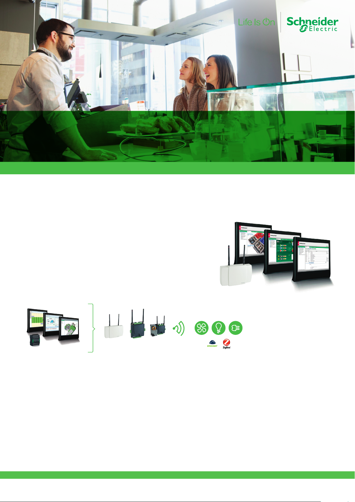
Schneider Electric EcoStruxure Building
EcoStruxure Building Expert Solution
Get control. Get efficient. Get value. Efficiency for small and
medium-sized buildings, and historic building retrofits.
EcoStruxure Building Expert solution is a fast, easy way to future-fit buildings
with a smaller footprint, delivering energy savings and comfort through
web and wireless technology to control HVAC, lighting, and metering. It is
powered by Building Expert Software, a fully programmable, no licensefee software, and hosted directly by the MultiPurpose Manager (MPM).
The MPM also serves as a wireless gateway for seamless communication
to EcoStruxure solution in historic site retrofits or other buildings where
wiring is prohibitive.
Save energy, save time, and improve comfort with minimal impact on
operations.
A10

 Loading...