

EasyLogic™PM2200 series
User Manual
NHA2778902-08
02/2021
www.se.com

Legal Information
The Schneider Electric brand and any trademarks of Schneider Electric SE and its
subsidiaries referred to in this guide are the property of Schneider Electric SE or its
subsidiaries. All other brands may be trademarks of their respective owners.
This guide and its content are protected under applicable copyright laws and
furnished for informational use only. No part of this guide may be reproduced or
transmitted in any form or by any means (electronic, mechanical, photocopying,
recording, or otherwise), for any purpose, without the prior written permission of
Schneider Electric.
Schneider Electric does not grant any right or license for commercial use of the guide
or its content, except for a non-exclusive and personal license to consult it on an "as
is" basis. Schneider Electric products and equipment should be installed, operated,
serviced, and maintained only by qualified personnel.
As standards, specifications, and designs change from time to time, information
contained in this guide may be subject to change without notice.
To the extent permitted by applicable law, no responsibility or liability is assumed by
Schneider Electric and its subsidiaries for any errors or omissions in the informational
content of this material or consequences arising out of or resulting from the use of the
information contained herein.
Safety information
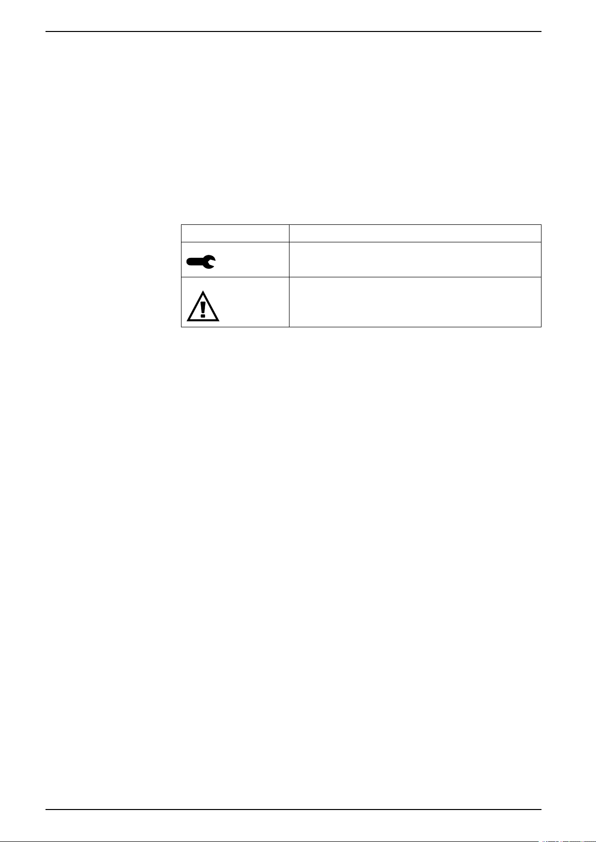
Important information
Read these instructions carefully and look at the equipment to become familiar
with the device before trying to install, operate, service, or maintain it. The
following special messages may appear throughout this manual or on the
equipment to warn of potential hazards or to call attention to information that
clarifies or simplifies a procedure.
The addition of either symbol to a “Danger” or “Warning” safety label indicates
that an electrical hazard exists which will result in personal injury if the
instructions are not followed.
This is the safety alert symbol. It is used to alert you to potential personal injury
hazards. Obey all safety messages that accompany this symbol to avoid possible
injury or death.
EasyLogic™PM2200 series
DANGER
DANGER indicates a hazardous situation which, if not avoided, will result in
death or serious injury.
Failure to follow these instructions will result in death or serious injury.
WARNING
WARNING indicates a hazardous situation which, if not avoided, could result
in death or serious injury.
CAUTION
CAUTION indicates a hazardous situation which, if not avoided, could result in
minor or moderate injury.
NOTICE
NOTICE is used to address practices not related to physical injury.
Please note
Electrical equipment should be installed, operated, serviced and maintained only
by qualified personnel. No responsibility is assumed by Schneider Electric for any
consequences arising out of the use of this material. A qualified person is one who
has skills and knowledge related to the construction, installation, and operation of
electrical equipment and has received safety training to recognize and avoid the
hazards involved.
NHA2778902-08 3

EasyLogic™PM2200 series
Notices
FCC
This equipment has been tested and found to comply with the limits for a Class A
digital device, pursuant to Part 15 of the FCC rules. These limits are designed to
provide reasonable protection against harmful interference when the equipment is
operated in a commercial environment. This equipment generates, uses, and can
radiate radio frequency energy and, if not installed and used in accordance with
the instruction manual, may cause harmful interference to radio communications.
Operation of this equipment in a residential area is likely to cause harmful
interference in which case the user will be required to correct the interference at
his own expense.
The user is cautioned that any changes or modifications not expressly approved
by Schneider Electric could void the user’s authority to operate the equipment.
This digital apparatus complies with CAN ICES-3 (A) /NMB-3(A).
4 NHA2778902-08

Table of Contents
Safety precautions ......................................................................................9
Introduction ................................................................................................10
Meter overview......................................................................................... 10
Meter Features......................................................................................... 10
Feature summary .....................................................................................10
Measured parameters...............................................................................12
Data display and analysis tools..................................................................14
Meter configuration...................................................................................14
EasyLogic™PM2200 series
Energy ...............................................................................................12
Non Reset energy............................................................................... 12
Demand .............................................................................................13
Instantaneous.....................................................................................13
Power quality...................................................................................... 13
Data recording (PM2230) .................................................................... 13
Input/output (PM2230)......................................................................... 14
Other measurements ..........................................................................14
Power Monitoring Expert .....................................................................14
Power SCADA Operation .................................................................... 14
Hardware references................................................................................ 16
PM2200 meter models and accessories .....................................................16
Supplemental information..........................................................................16
Panel meter .............................................................................................16
Meter mounting ........................................................................................17
Meter wiring considerations....................................................................... 17
Direct connect voltage limits ................................................................ 17
Balanced system considerations .......................................................... 19
RS-485 wiring ..........................................................................................19
Pulse output............................................................................................. 20
Meter display .............................................................................................21
Display overview ......................................................................................21
LED indicators.......................................................................................... 21
Alarm / energy pulsing LED .................................................................21
Heartbeat / serial communications LED ................................................21
Notification icons ......................................................................................22
Meter display language .............................................................................22
Meter screen navigation............................................................................ 22
Navigation symbols............................................................................. 23
Meter screen menus overview .............................................................23
Setting up the display................................................................................24
Basic setup ................................................................................................25
Configuring basic setup parameters using the display .................................25
Configuring advanced setup parameters using the display...........................27
Setting the rate......................................................................................... 28
Setting up regional settings .......................................................................28
Setting up the screen passwords ...............................................................29
Lost password .................................................................................... 30
Setting the clock ................................................................................. 30
NHA2778902-08 5

EasyLogic™PM2200 series
SnapShot.................................................................................................30
Viewing SnapShot page ......................................................................31
SnapShot setting ................................................................................31
Retrofit..................................................................................................... 31
Retrofit setting .................................................................................... 31
Configuring Favorite Page......................................................................... 32
Auto reset configuration ............................................................................32
I/O Modules................................................................................................34
Analog input applications ..........................................................................34
Analog output applications ........................................................................ 36
Status input (DI) applications .....................................................................38
Digital output applications .........................................................................39
Relay output applications .......................................................................... 40
IO LED Indicator.......................................................................................42
Alarms......................................................................................................... 43
Alarms overview ....................................................................................... 43
Alarm types.............................................................................................. 43
Unary alarms............................................................................................ 43
Available unary alarms ........................................................................43
Digital alarms ........................................................................................... 44
Available digital alarms ........................................................................44
Standard alarms....................................................................................... 44
Example of over and under setpoint (standard) alarm operation..............44
Maximum allowable setpoint................................................................46
Available standard alarms ................................................................... 46
Alarm priorities .........................................................................................48
Alarm setup overview................................................................................ 49
LED alarm indicator ..................................................................................51
Configuring the LED for alarms using the display...................................51
Configuring the LED for alarms using ION Setup ...................................51
Alarm display and notification ....................................................................51
Active alarms list and alarm history log ....................................................... 52
Alarms counters .......................................................................................53
Resetting alarms using ION Setup .............................................................53
Meter logging .............................................................................................54
Logs overview ..........................................................................................54
Setting up the data log .............................................................................. 54
Saving the data log contents using ION Setup ............................................54
Alarm log .................................................................................................55
Meter resets ...............................................................................................56
Meter resets............................................................................................. 56
Meter initialization.....................................................................................56
Performing resets using ION Setup ...................................................... 56
Measurements and calculations ............................................................. 58
Meter initialization.....................................................................................58
Real-time readings ...................................................................................58
Energy measurements..............................................................................58
Quadrant based VARh ..............................................................................59
Min/max values ........................................................................................59
Power demand .........................................................................................59
6 NHA2778902-08

EasyLogic™PM2200 series
Power demand calculation methods ..................................................... 59
Block interval demand .........................................................................59
Synchronized demand......................................................................... 61
Thermal demand ................................................................................61
Current demand .......................................................................................61
Predicted demand............................................................................... 61
Peak demand ..................................................................................... 62
Timer.......................................................................................................62
Multi-tariff ...................................................................................................63
Multi-tariff implementation .........................................................................63
Command mode overview......................................................................... 63
Time of day mode overview ....................................................................... 64
Time of day mode tariff validity .............................................................64
Time of day tariff creation methods .......................................................64
Example tariff configurations for a four-tariff system ...............................65
Input mode overview.................................................................................65
Digital input assignment for input control mode......................................66
Active tariff control mode ...........................................................................66
Configuring time of day mode tariffs using the display ............................67
Configuring input mode tariffs using the display .....................................68
Power quality .............................................................................................69
Harmonics overview ................................................................................. 69
Total harmonic distortion %........................................................................69
Harmonic content calculations ............................................................. 69
THD% calculations..............................................................................69
thd calculations...................................................................................69
Viewing THD/thd using the display ....................................................... 70
Maintenance and upgrades..................................................................... 71
Maintenance overview ..............................................................................71
Troubleshooting LED indicators .................................................................71
Meter memory..........................................................................................71
Meter battery............................................................................................71
Viewing firmware version, model and serial number ....................................72
Firmware upgrades................................................................................... 72
Technical assistance .................................................................................72
Verifying accuracy..................................................................................... 73
Overview of meter accuracy ...................................................................... 73
Accuracy test requirements .......................................................................73
Verifying accuracy test ..............................................................................74
Required pulses calculation for accuracy verification testing ........................ 75
Total power calculation for accuracy verification testing ...............................76
Percentage error calculation for accuracy verification testing ....................... 76
Accuracy verification test points.................................................................76
Energy pulsing considerations ...................................................................77
VT and CT considerations..........................................................................77
Example calculations ................................................................................78
Typical sources of test errors .....................................................................79
Power and power factor ...........................................................................80
Power and power factor ............................................................................ 80
Current phase shift from voltage ................................................................80
NHA2778902-08 7

EasyLogic™PM2200 series
Real, reactive and apparent power (PQS)................................................... 80
Power factor (PF) ..................................................................................... 81
Power factor sign convention ...............................................................81
Power factor min/max convention.........................................................82
Power factor register format................................................................. 82
Specifications ............................................................................................84
China Standard Compliance ...................................................................90
8 NHA2778902-08
Safety precautions EasyLogic™PM2200 series
Safety precautions
Installation, wiring, testing and service must be performed in accordance with all
local and national electrical codes.
DANGER
HAZARD OF ELECTRIC SHOCK, EXPLOSION, OR ARC FLASH
• Apply appropriate Personal Protective Equipment (PPE) and follow safe
electrical work practices. See NFPA 70E, CSA Z462 or other local
standards.
• Turn off all power supplying this device and the equipment in which it is
installed before working on or in the equipment.
• Always use a properly rated voltage sensing device to confirm that all power
is off.
• Follow guidelines in the Wiring section of the related Installation Sheet.
• Assume communications and I/O wiring are hazardous live until determined
otherwise.
• Do not exceed the maximum ratings of this device.
• Do not short secondary terminals of Voltage Transformer (VT).
• Do not open secondary terminals of Current Transformer (CT).
• Ground secondary circuit of CTs.
• Do not use the data from the meter to confirm power is off.
• Replace all devices, doors and covers before turning on power to this
equipment.
Failure to follow these instructions will result in death or serious injury.
NOTE: See IEC 60950-1 for more information on communications and I/O
wiring connected to multiple devices.
WARNING
UNINTENDED OPERATION
• Do not use this device for critical control or protection of persons, animals,
property or equipment.
Failure to follow these instructions can result in death, serious injury, or
equipment damage.
WARNING
POTENTIAL COMPROMISE OF SYSTEM AVAILABILITY, INTEGRITY, AND
CONFIDENTIALITY
• Change default passwords/passcodes to help prevent unauthorized access
to device settings and information.
• Disable unused ports/services and default accounts, where possible, to
minimize pathways for malicious attacks.
• Place networked devices behind multiple layers of cyber defenses (such as
firewalls, network segmentation, and network intrusion detection and
protection).
• Use cybersecurity best practices (for example: least privilege, separation of
duties) to help prevent unauthorized exposure, loss, modification of data and
logs, interruption of services, or unintended operation.
Failure to follow these instructions can result in death, serious injury, or
equipment damage.
NHA2778902-08 9

EasyLogic™PM2200 series Introduction
Introduction
Meter overview
The PM2200 series meters are digital meters that offer comprehensive 3-phase
electrical instrumentation and load management facilities in a compact and rugged
package.
The meters offer value for the demanding needs of your energy monitoring and
cost management applications. All meters in the PM2200 series range comply
with Class 1, or Class 0.5S accuracy standards and feature high quality, reliability
and affordability in a compact and easy to install format.
Meter Features
The PM2200 series meter supports many features, a few of the features are listed
below:
• Self guided LCD display and navigation
• Energy accounting and balancing
• Measurement of both True PF and Displacement PF
• Active, reactive, and apparent energy readings
• Min/Max values of instantaneous parameters with timestamp.
• Cybersecurity: The meter supports the disabling of RS-485 port through front
panel keys to prevent unauthorized access. Toggle the RTU devices in case
of limited availability of nodes in software system.
• SnapShot: The meter features include snapshot, which captures values of
average voltage, average current, total active power, and delivered energy
based on configured time in HH.MM format.
• Suppression current: This is the minimum current at which the meter starts
functioning. The meter can be configured to disregard the measurement of
induced / auxiliary load current in the circuit. The suppression current
selection can be done through the front display and through communication.
The suppression current range is from 5 mA to 99 mA. The meter shows
measurement if applied value is above the suppression value. The default
suppression current is 5 mA.
You can use the meter as a stand-alone device, but its extensive capabilities are
fully realized when used as part of an energy management system.
For applications, feature details and the most current and complete specifications
of the PM2200 meters, see the EasyLogic PM2000 series technical datasheet at
www.se.com.
Feature summary
Parameter PM2210 PM2220 PM2230
Accuracy Class for Wh Class 1 Class 1 Class 0.5S
Accuracy Class for VARh 1.0 1.0 1.0
Sampling rate per cycle 64 64 64
Current:
• Per-phase and 3 phase average
• Calculated neutral current
Voltage:
• V L-N - per-phase and 3 phase average
• V L-L - per-phase and 3 phase average
10 NHA2778902-08
✔ ✔ ✔
✔ ✔ ✔

Introduction EasyLogic™PM2200 series
Parameter PM2210 PM2220 PM2230
Power Factor
• Per phase and 3 phase total
True PF True PF
Displacement PF
True PF
Displacement PF
Frequency
Power:
✔ ✔ ✔
✔ ✔ ✔
• Active power (kW) - Phase wise and total
• Apparent power (kVA) - Phase wise and total
• Reactive power (kVAR) - Phase wise and total
3 Phase unbalance Current Current
Voltage
Demand parameters (kW, kVA, kVAR, I)
• Last demand
✔
(no timestamp)
✔ ✔
Current
Voltage
• Present demand
• Predictive demand
• Peak demand: Timestamp for peak demand
Energy: kWh, kVAh, kVARh (4 Quadrant) - Phase wise
total
• Delivered (Import / Forward)
• Received (Export / Reverse)
THD, thd:
1
2
and
Delivered (D)
Received (R)
Total (D+R)
Net (D-R)
Delivered (D)
Received (R)
Total (D+R)
Net (D-R)
Last cleared (Old)
Delivered (D)
Received (R)
Total (D+R)
Net (D-R)
1
Last cleared (Old)
1
✔ ✔ ✔
• Voltage L-N per phase
• Voltage L-L per phase
• Current per phase
Individual Harmonics
Min / Max with timestamp
—
—
Up to 15th individual
harmonics
✔ ✔
Up to 31st individual
harmonics
• V L-L average
• V L-N average
• Current average
• Neutral current
• Frequency
• Active power, Total
• Apparent power, Total
• Reactive power, Total
• Power factor, Total
Communication POP RS-485 Modbus RTU RS-485 Modbus RTU
Expandable Analog IO modules (1 input & 1 output)
Expandable Analog IO modules (2 inputs & 2 outputs)
Expandable Digital IO modules (2 inputs & 2 outputs)
Expandable Relay Output modules (2 digital inputs & 2 relay
— —
— —
— —
— —
✔
✔
✔
✔
outputs)
Data Logging
— —
✔
• Energy (Wh, VAh, VARh): Delivered / Received
• Power: Active / Apparent / Reactive (total)
• Demand (W, VA, VAR, A): Last
Retrofit
—
✔ ✔
For configuring legacy communication data models.
SnapShot
—
✔ ✔
1. Indicated features can be read through communication only.
2. The Phase wise energy is applicable only for 3PH4W configurations.
NHA2778902-08 11

EasyLogic™PM2200 series Introduction
Parameter PM2210 PM2220 PM2230
Multi-tariff
Auto reset
3
— —
—
✔
✔ ✔
Measured parameters
Energy
The meter provides bi-directional, 4-quadrant, Class 1 / Class 0.5S accurate
energy metering.
The meter stores all accumulated active, reactive, and apparent energy
parameters in nonvolatile memory:
The meter provides both per phase and total values of energy.
Total energy:
• kWh, kVARh, kVAh (delivered)
• kWh, kVARh, kVAh (received)
• kWh, kVARh, kVAh (delivered + received)
• kWh, kVARh, kVAh (delivered - received)
Per phase energy:
• kWh1, kWh2, kWh3, kVARh1, kVARh2, kVARh3, kVAh1, kVAh2, kVAh3
(delivered)
• kWh1, kWh2, kWh3, kVARh1, kVARh2, kVARh3, kVAh1, kVAh2, kVAh3
(received)
• kWh1, kWh2, kWh3, kVARh1, kVARh2, kVARh3, kVAh1, kVAh2, kVAh3
(delivered + received)
• kWh1, kWh2, kWh3, kVARh1, kVARh2, kVARh3, kVAh1, kVAh2, kVAh3
(delivered - received)
NOTE: Based on the energy scale selection, when kWh, kWh1, kWh2, kWh3,
kVARh, kVARh1, kVARh2, kVARh3, kVAh, kVAh1, kVAh2, kVAh3 (delivered) or
kWh, kWh1, kWh2, kWh3, kVARh, kVARh1, kVARh2, kVARh3, kVAh, kVAh1,
kVAh2, kVAh3 (received) of the energy parameters overflow at 999.99 all energy
parameter value resets.
NOTE: The energy per phase displays on the HMI for the 3PH4W configurations
(3PH4W Opn Dlt Ctr Tp, 3PH4W Dlt Ctr Tp, 3PH4W Wye Ungnd,
3PH4W Wye Gnd, and 3PH4W Wye Res Gnd) only. For other configurations, the
energy per phase is not displayed on HMI and obtains as "0" through
communication.
Non Reset energy
Non Reset energy parameters are Wh, VAh and VARh for both Del and Rec. Non
Reset energy parameters are available on display in Diag page under
Maintenance and through communication..
These parameter values cannot be reset either through display or communication.
These Non Reset energy values will overflow automatically when they reach
maximum value based on overflow limit.
Command Accumulated
Reset sub systems Clear No Clear Clear
Initialization Clear No Clear Clear
3. Indicated features can be read through communication only.
energies
Non Reset
energies
Old energies
12 NHA2778902-08

Introduction EasyLogic™PM2200 series
Demand
Instantaneous
Command Accumulated
Reset all energies Clear No clear No clear (update with
Reset all accumulated
energies (total, per phase)
energies
Clear No clear No clear (update with
Non Reset
energies
Old energies
Accumulated
energies)
Accumulated
energies)
The meter provides last, present, predicted, and maximum (peak) demand values,
and a timestamp when the maximum (peak) demand occurred.
The meter supports standard demand calculation methods, including sliding block,
fixed block, rolling block, thermal and synchronized.
Peak demand registers can be reset manually (password protected).
Demand measurements include:
• W, VAR, VA demand total
• Amps demand average
Power quality
The meter provides highly accurate 1-second measurements, average values,
including true RMS, per phase and total for:
• Per phase and average voltage (line-to-line, line-to-neutral)
• Per phase and average current, and neutral current
NOTE: Neutral current is calculated.
• Per phase and total power (VA, W, Var)
• Per phase and average for true and displacement power factor
• System frequency
• Per phase and maximum of all three for voltage unbalance and current
unbalance
The meter provides complete harmonic distortion metering, recording, and realtime reporting, up to the 15
th
harmonic for PM2220 and up to 31stharmonic for
PM2230 for all voltage and current inputs.
The following power quality measurements are available:
• PM2220: Individual odd harmonics up to 15
th
order (Voltage and current, per
phase)
• PM2230: Individual odd harmonics up to 31
st
order (Voltage and current, per
phase)
• Total harmonic distortion (THD%) for current and voltage (displays line-to-line
or line-to-neutral, based on selected system configuration)
Data recording (PM2230)
The meter stores each new minimum and new maximum value with date and
timestamp for all instantaneous values (average, total, and each phase).
The meter also records the following:
• Alarms (with 1s timestamping)
• Parameters configured for data logging
NHA2778902-08 13

EasyLogic™PM2200 series Introduction
• Data, alarm history, and diagnostics logs
Input/output (PM2230)
The meter supports optional input and output capabilities.
Other measurements
Additional measurements recorded by the meter include several timers.
These timers include:
• I/O timer displays the powered ON duration of the input or output.
• Operating timer displays the powered ON duration of the meter.
• Active load timer displays the duration of the connected load, based on the
specified minimum current for the load timer setpoint setting.
Data display and analysis tools
Power Monitoring Expert
Power SCADA Operation
EcoStruxure™Power Monitoring Expert is a complete supervisory software
package for power management applications.
The software collects and organizes data gathered from your facility’s electrical
network and presents it as meaningful, actionable information via an intuitive web
interface.
Power Monitoring Expert communicates with devices on the network to provide:
• Real-time monitoring through a multi-user web portal
• Trend graphing and aggregation
• Power quality analysis and compliance monitoring
• Preconfigured and custom reporting
See the EcoStruxure
how to add your device into its system for data collection and analysis.
EcoStruxure™Power SCADA Operation is a complete real-time monitoring and
control solution for large facility and critical infrastructure operations.
It communicates with your device for data acquisition and real-time control. You
can use Power SCADA Operation for:
• System supervision
• Real-time and historical trending, event logging
• PC-based custom alarms
See the EcoStruxure
how to add your device into its system for data collection and analysis.
™
Power Monitoring Expert online help for instructions on
™
Power SCADA Operation online help for instructions on
Meter configuration
Meter configuration can be performed through the display or PowerLogic™ION
Setup.
ION Setup is a meter configuration tool that can be downloaded for free at
www.se.com.
14 NHA2778902-08

Introduction EasyLogic™PM2200 series
See the ION Setup online help or in the ION Setup device configuration guide. To
download a copy, go to www.se.com and search for ION Setup device
configuration guide.
NHA2778902-08 15

EasyLogic™PM2200 series Hardware references
Hardware references
PM2200 meter models and accessories
The meter is available in several different models with optional accessories that
provide various mounting options.
Meter models
Model Commercial reference Description
PM2210 METSEPM2210 Front panel mount, 96 x 96 mm form factor, EasyLogic VAF Power
PM2220 METSEPM2220 Front panel mount, 96 x 96 mm form factor, EasyLogic VAF Power
PM2230 METSEPM2230 Front panel mount, 96 x 96 mm form factor, EasyLogic VAF Power
and Energy meter with THD and POP. Complies with accuracy
class 1.
and Energy meter with RS-485 communication and odd harmonics
th
up to 15
and Energy meter with RS-485 communication and odd harmonics
up to 31
order. Complies with accuracy class 1.
st
order. Complies with accuracy class 0.5S.
Meter accessories
Model Commercial reference Description
2 Channel Digital Input
Output Module
2 Channel Analog Input
Output Module
1 Channel Analog Input
Output Module
2 Channel Digital Input
and Relay Output
Module
METSEPM2KDGTLIO22 and
METSEPM2KDGTLIO22D
METSEPM2KANLGIO22 and
METSEPM2KANLGIO22D
METSEPM2KANLGIO11 and
METSEPM2KANLGIO11D
METSEPM2K2DI2RO and
METSEPM2K2DI2ROD
NOTE: The I/O modules are supported by PM2230 meter models only.
See the PM2000 series catalog pages, available from www.se.com, or consult
your local Schneider Electric representative for information about mounting
adapters available for your meter.
Digital I/O module with 2 channel input and output.
Analog I/O module with 2 channel input and output.
Analog I/O module with single channel input and output.
Relay module with dual channel digital input and relay output.
Supplemental information
This document is intended to be used in conjunction with the installation sheet that
ships in the box with your device and accessories.
See your device’s installation sheet for information related to installation.
See your product’s catalog pages at www.se.com for information about your
device, its options and accessories.
You can download updated documentation from www.se.com or contact your local
Schneider Electric representative for the latest information about your product.
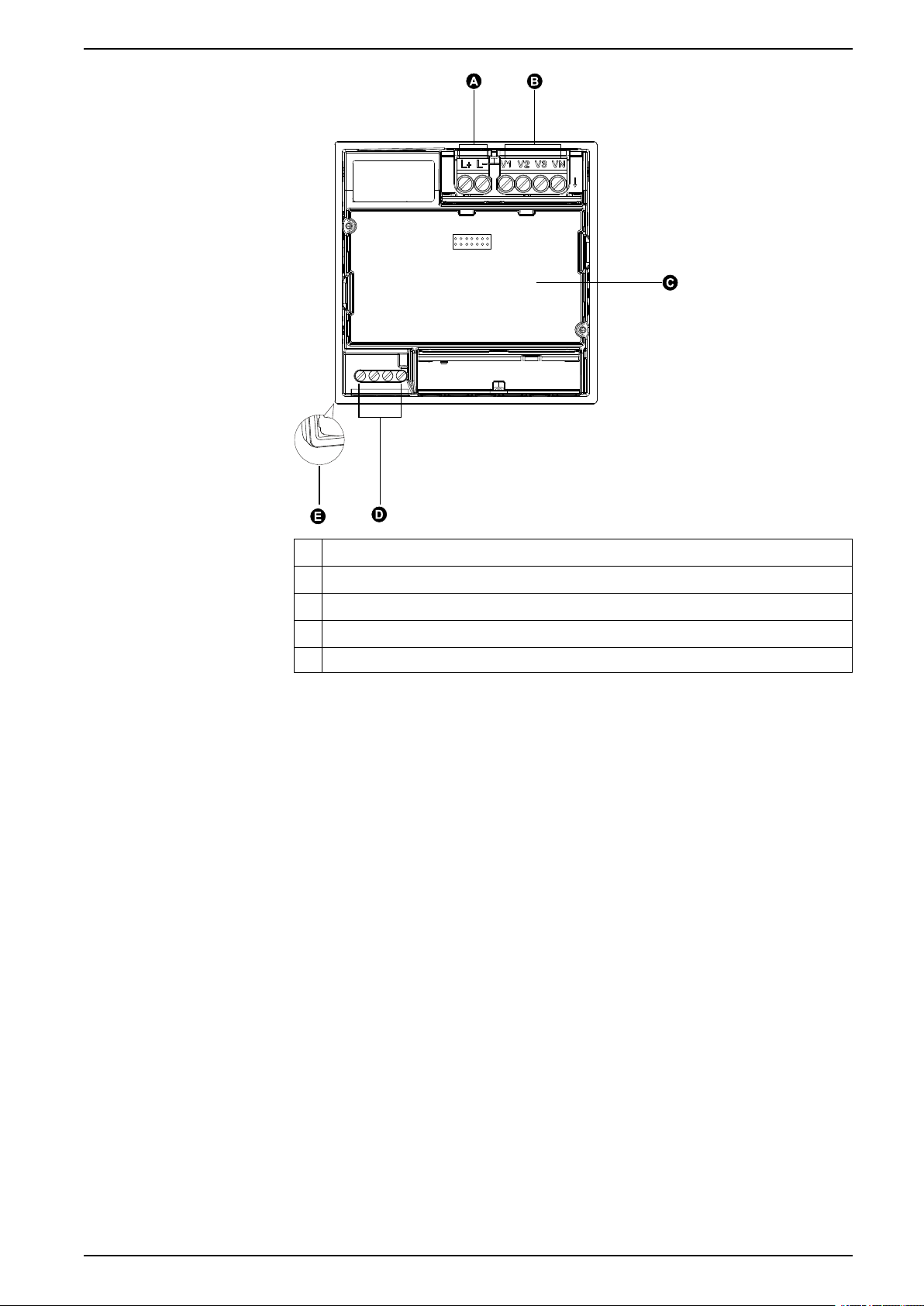
Panel meter
The back of your meter supports various power system connections.
16 NHA2778902-08
Hardware references EasyLogic™PM2200 series
A Auxiliary power supply (control power) terminals (L1 / L+ , L2 / L-)
B Input voltage terminals (V1, V2, V3, VN)
C I/O card (PM2230R only)
D RS-485 communications (D0, D1, SHLD, 0V)
E Gasket
Meter mounting
For mounting instructions and safety precautions, see the installation sheet that
was shipped with your device
You can also download the latest copy at www.se.com.
Meter wiring considerations
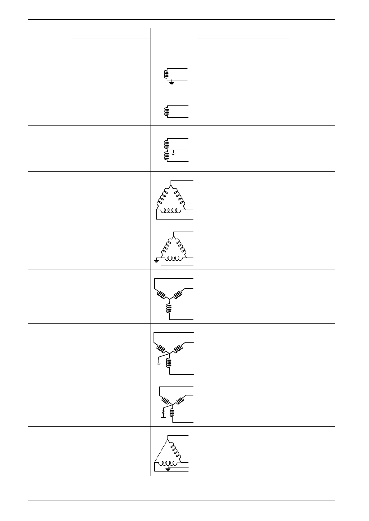
Direct connect voltage limits
You can connect the meter’s voltage inputs directly to the phase voltage lines of
the power system if the power system’s line-to-line or line-to-neutral voltages do
not exceed the meter’s direct connect maximum voltage limits.
The meter's voltage measurement inputs are rated by the manufacturer for up to
277 V L-N / 480 V L-L. However, the maximum voltage allowed for direct
connection may be lower, depending on the local electrical codes and regulations.
As per installation category II / III the maximum voltage on the meter voltage
measurement inputs should not exceed 277 V L-N / 480 V L-L for CAT III and 347
V L-N / 600 V L-L for CAT II.
If your system voltage is greater than the specified direct connect maximum
voltage, you must use VTs (voltage transformers) to step down the voltages.
NHA2778902-08 17
EasyLogic™PM2200 series Hardware references
N
Power system
description
Single-phase 2wire line-toneutral
Single-phase 2wire line-to-line
Single-phase 3wire line-to-line
with neutral
3-phase 3-wire
Delta
ungrounded
Meter setting Symbol Direct connect maximum (UL / IEC) # of VTs (if
required)
Display
(meter)
1PH2W LN 1PH 2Wire L-N
1PH2W LL 1PH 2Wire L-L
1PH3W LL
With N
3PH3W Dlt
Ungnd
Display
(communication)
1PH 3Wire L-L
with N
3PH 3Wire
Ungrounded Delta
Installation
category III
Installation
category II
≤ 277 V L-N ≤ 347 V L-N 1 VT
480 V L-L 600 V L-L 1 VT
≤ 277 V L-N / 480
V L-L
≤ 347 V L-N / 600
V L-L
2 VT
480 V L-L 600 V L-L 2 VT
3-phase 3-wire
Delta corner
grounded
3-phase 3-wire
Wye ungrounded
3-phase 3-wire
Wye grounded
3-phase 3-wire
Wye resistancegrounded
3PH3W Dlt
Crnr Gnd
3PH3W
Wye Ungnd
3PH3W
Wye Gnd
3PH3W
Wye Res
Gnd
3PH 3Wire
Corner Grounded
Delta
3PH 3Wire
Ungrounded Wye
3PH 3Wire
Grounded Wye
3PH 3Wire
Resistance
Grounded Wye
480 V L-L 600 V L-L 2 VT
480 V L-L 600 V L-L 2 VT
480 V L-L 600 V L-L 2 VT
480 V L-L 600 V L-L 2 VT
3-phase 4-wire
open Delta
center-tapped
3PH4W
Opn Dlt Ctr
Tp
3PH 4Wire
Center-Tapped
Open Delta
240 V L-N / 480 V
L-L
240 V L-N / 480 V
L-L
3 VT
18 NHA2778902-08
Hardware references EasyLogic™PM2200 series
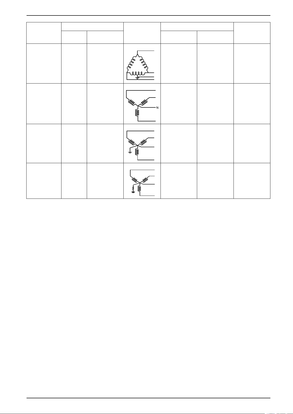
N
N
N
Power system
description
3-phase 4-wire
Delta centertapped
3-phase 4-wire
ungrounded Wye
3-phase 4-wire
grounded Wye
3-phase 4-wire
resistancegrounded Wye
Meter setting Symbol Direct connect maximum (UL / IEC) # of VTs (if
Display
(meter)
3PH4W Dlt
Ctr Tp
3PH4W
Wye Ungnd
3PH4W
Wye Gnd
3PH4W
Wye Res
Gnd
Display
(communication)
3PH 4Wire
Center-Tapped
Delta
3PH 4Wire
Ungrounded Wye
3PH 4Wire
Grounded Wye
3PH 4Wire
Resistance
Grounded Wye
Installation
category III
240 V L-N / 480 V
L-L
≤ 277 V L-N / 480
V L-L
≤ 277 V L-N / 480
V L-L
≤ 277 V L-N / 480
V L-L
Installation
category II
240 V L-N / 480 V
L-L
≤ 347 V L-N / 600
V L-L
≤ 347 V L-N / 600
V L-L
≤ 347 V L-N / 600
V L-L
required)
3 VT
3 VT or 2 VT
3 VT or 2 VT
3 VT or 2 VT
Balanced system considerations
In situations where you are monitoring a balanced 3-phase load, you may choose
to connect only one or two CTs on the phase(s) you want to measure, and then
configure the meter so it calculates the current on the unconnected current
input(s).
NOTE: For a balanced 4-wire Wye system, the meter’s calculations assume
that there is no current flowing through the neutral conductor.
Balanced 3-phase Wye system with 2 CTs
The current for the unconnected current input is calculated so that the vector sum
for all three phases equal zero.
Balanced 3-phase Wye or Delta system with 1CT
The currents for the unconnected current inputs are calculated so that their
magnitude and phase angle are identical and equally distributed, and the vector
sum for all three phase currents equal zero.
NOTE: You must always use 3 CTs for 3-phase 4-wire center-tapped Delta or
center-tapped open Delta systems.
RS-485 wiring
Connect the devices on the RS-485 bus in a point-to-point configuration, with the
(+) and (-) terminals from one device connected to the corresponding (+) and (-)
terminals on the next device.
NHA2778902-08 19
EasyLogic™PM2200 series Hardware references
D1+
≤40V
≤20mA
D1-
(60)
(61)
RS-485 cable
Use a shielded 2 twisted pair or 1.5 twisted pair RS-485 cable to wire the devices.
Use one twisted pair to connect the (+) and (-) terminals, and use the other
insulated wire to connect the C terminals
The total distance for devices connected on an RS-485 bus should not exceed
1000 m (3280 ft).
RS-485 terminals
C Common. This provides the voltage reference (zero volts) for the data plus and data minus
signals
Shield. Connect the bare wire to this terminal to help suppress signal noise that may be
present. Ground the shield wiring at one end only (either at the master or the last slave
device, but not both.
-
Data minus. This transmits/receives the inverting data signals.
+
Data plus. This transmits/receives the non-inverting data signals.
NOTE: If some devices in your RS-485 network do not have the C terminal,
use the bare wire in the RS-485 cable to connect the C terminal from the
meter to the shield terminal on the devices that do not have the C terminal.
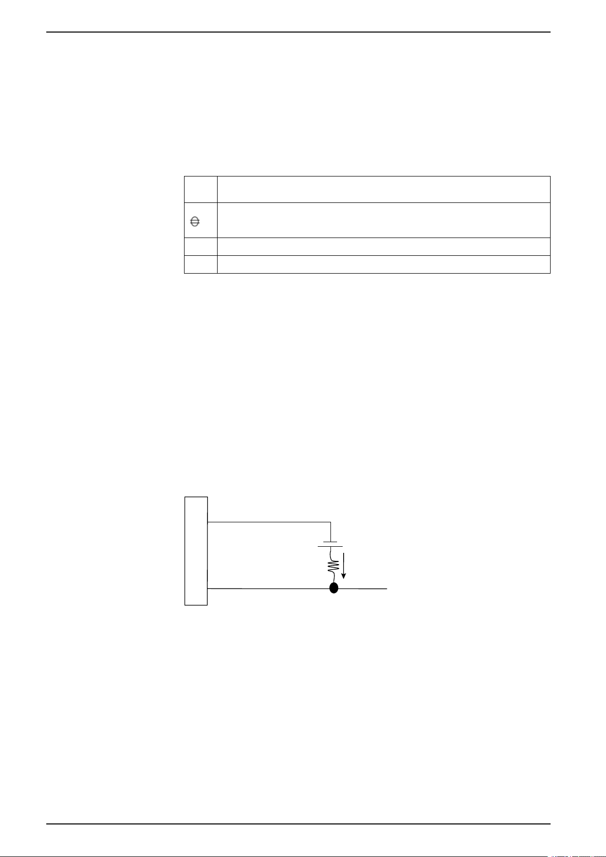
Pulse output
NOTE: Applicable only for PM2210 meter model
The meter is equipped with one pulse output port (D1+, D1-).
You can configure the pulse outputs for use in the following application:
• energy pulsing applications, where a receiving device determines energy
usage by counting the k_h pulses coming from the meter’s pulse output port.
One pulse output can handle voltage less than or equal to 40 V DC (20 mA
maximum). For higher voltage applications, use an external relay in the switching
circuit.
20 NHA2778902-08
Meter display EasyLogic™PM2200 series
C
G
E
F
D
B
A
H
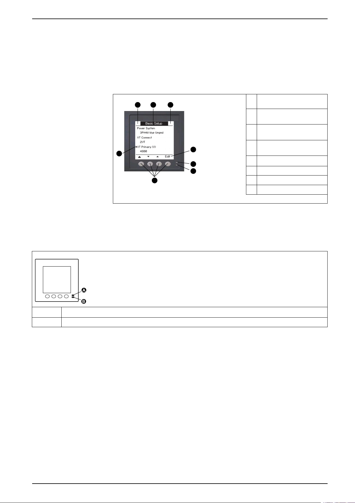
Meter display
Display overview
The display (integrated or remote) lets you use the meter to perform various tasks
such as setting up the meter, displaying data screens, acknowledging alarms, or
performing resets.
A Navigation / menu selection
buttons
B Heartbeat / communications
LED (green)
C Alarm / energy pulsing LED
(orange)
D Navigation symbols or menu
options
E Right notification area
F Screen title
G Left notification area
H Cursor
LED indicators
The LED indicators alert or inform you of meter activity.
A Alarm / energy pulsing LED
B Heartbeat / serial communications LED
Alarm / energy pulsing LED
The alarm / energy pulsing LED can be configured for alarm notification or energy
pulsing.
When configured for alarm notification, this LED blinks every one second
indicating that a high, medium or low priority alarm is tripped. The LED provides a
visual indication of an active alarm condition or an inactive but unacknowledged
high priority alarm.
When configured for energy pulsing, this LED flashes at a rate proportional to the
amount of energy consumed. This is typically used to verify the power meter’s
accuracy.
Heartbeat / serial communications LED
The heartbeat / serial communications LED blinks to indicate the meter’s
operation and serial Modbus communications status.
NHA2778902-08 21
EasyLogic™PM2200 series Meter display
The LED blinks at a slow, steady rate to indicate the meter is operational. The LED
flashes at a variable, faster rate when the meter is communicating over a Modbus
serial communications port.
You cannot configure this LED for other purposes.
NOTE: A heartbeat LED that remains lit and does not blink (or flash) can
indicate a problem. In this case, power down the meter and reapply power. If
the LED still does not blink or flash, contact Technical Support.
Notification icons
To alert you about meter state or events, notification icons appear at the top left or
top right corner of the display screen.
Icon Description
The wrench icon indicates that the power meter is in an overvoltage
condition or requires maintenance. It could also indicate that the
energy LED is in an overrun state.
The alarm icon indicates an alarm condition has occurred.
Meter display language
If your meter is equipped with a display screen, you can configure the meter to
display the measurements in one of several languages.
The following languages are available:
• English
• French
• Spanish
• German
• Portuguese
• Russian
• Chinese
• Turkish
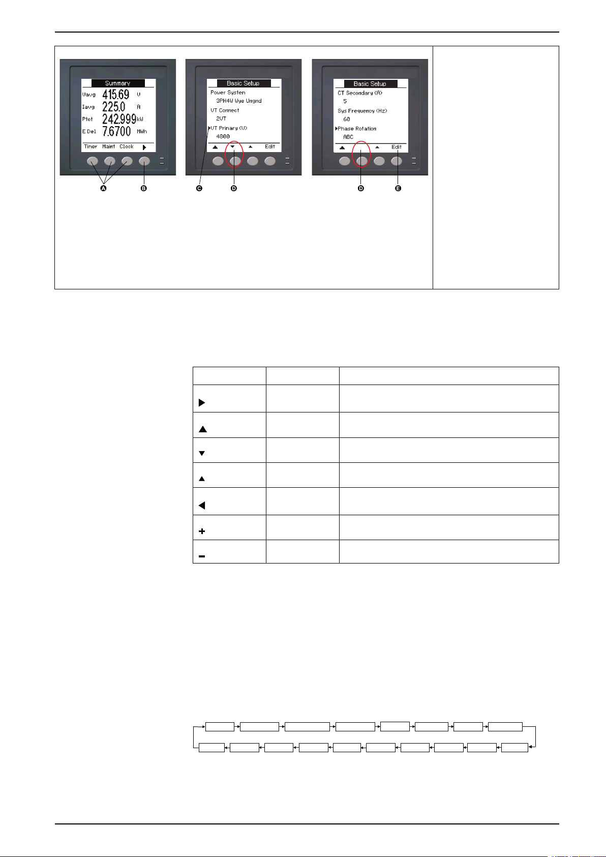
Meter screen navigation
The meter’s buttons and display screen allow you to navigate data and setup
screens, and to configure the meter’s setup parameters.
22 NHA2778902-08
Meter display EasyLogic™PM2200 series
Amps [I] Volts [U-V] Energy [E]
PF
Hz [F]
Maint
Power [PQS]
THD
Unbal
MnMx
(+2)
Alarm
(+3)
Timer
(+2)
Clock
(+2)
Harm
(+2)
Rate
Fav
(+2)
Snap
(+2)
I/O
(+3)
(+2)
Applicable only for PM2220/PM2230 meter models
(+3)
Applicable only for PM2230 meter model
A. Press the button below the
appropriate menu to view
that screen
B. Press the right arrow to
view more screens
C. In setup mode, a small
right arrow indicates the
selected option
D. In setup mode, a small
down arrow indicates that
there are additional
parameters to display. The
down arrow disappears
when there are no more
parameters to display.
E. In setup mode, press the
button under Edit to
change that setting. If the
item is read-only, cannot
be configured with the
meter’s existing setup, or
can only be configured
using software, Edit
disappears.
Navigation symbols
Navigation symbols indicate the functions of the associated buttons on your
meter’s display.
Symbol Description Actions
When you reach the last screen, press the right arrow again to cycle through the
screen menus.
Meter screen menus overview
Right arrow Scroll right and display more menu items or move cursor
one character to the right
Up arrow Exit screen and go up one level
Small down
arrow
Move cursor down the list of options or display more items
below
Small up arrow Move cursor up the list of items or display more items
above
Left arrow Move cursor one character to the left
Plus sign Increase the highlighted value or show the next item in the
list.
Minus sign Show the previous item in the list
NHA2778902-08 23
All meter screens are grouped logically, according to their function.
You can access any available meter screen by first selecting the Level 1 (top level)
screen that contains it.
Level 1 screen menus - IEEE title [IEC title]

EasyLogic™PM2200 series Meter display
Setting up the display
You can change the display screen’s settings, such as contrast, backlight timeout,
and screen timeout .
1. Navigate to Maint > Setup.
2. Enter the setup password (default is “0”), then press OK.
3. Navigate to HMI > Disp.
4. Move the cursor to point to the parameter you want to modify, then press
Edit.
5. Modify the parameter as required, then press OK.
6. Move the cursor to point to the next parameter you want to modify, press Edit,
make your changes, then press OK.
7. Press the up arrow to exit.
8. Press Yes to save your changes.
Display settings available using the display
Parameter Values Description
Contrast 1 - 9 Increase or decrease the value to increase or decrease
Bcklght Timeout
(min)
Screen Timeout
(min)
0 - 60 Set how long (in minutes) before the backlight turns off
0 - 60 Set how long (in minutes) before the screen turns off
the display contrast.
after a period of inactivity. Setting this to “0” disables
the backlight timeout feature (i.e., backlight is always
on).
after a period of inactivity. Setting this to “0” disables
the screen timeout feature (i.e., display is always on).
To configure the display using ION Setup, see the “PM2000” topic in the ION
Setup online help or in the ION Setup device configuration guide, available for
download at www.se.com.
24 NHA2778902-08

Basic setup EasyLogic™PM2200 series
Basic setup
Configuring basic setup parameters using the display
You can configure basic meter parameters using the display.
Proper configuration of the meter’s basic setup parameters is essential for
accurate measurement and calculations. Use the Basic Setup screen to define the
electrical power system that the meter is monitoring.
If standard (1-sec) alarms have been configured and you make subsequent
changes to the meter’s basic setup, all alarms are disabled to prevent undesired
alarm operation.
NOTICE
UNINTENDED EQUIPMENT OPERATION
• Verify all standard alarms settings are correct and make adjustments as
necessary.
• Re-enable all configured alarms.
Failure to follow these instructions can result in equipment damage.
After saving the changes, confirm all configured standard alarm settings are still
valid, reconfigure them as required, and re-enable the alarms.
1. Navigate to Maint > Setup.
2. Enter the setup password (default is “0”), then press OK.
3. Navigate to Meter > Basic.
4. Move the cursor to point to the parameter you want to modify, then press
Edit.
5. Modify the parameter as required, then press OK.
6. Move the cursor to point to the next parameter you want to modify, press Edit,
make your changes, then press OK.
NHA2778902-08 25

EasyLogic™PM2200 series Basic setup
7. Press Yes to save your changes.
Basic setup parameters available using the display
Values Description
Power System
Select the power system type (power transformer) the meter is wired to.
1PH2W LN Single-phase 2-wire line-to-neutral
1PH2W LL Single-phase 2-wire line-to-line
1PH3W LL with N Single-phase 3-wire line-to-line with neutral
3PH3W Dlt Ungnd 3-phase 3-wire ungrounded delta
3PH3W Dlt Crnr Gnd 3-phase 3-wire corner grounded delta
3PH3W Wye Ungnd 3-phase 3-wire ungrounded wye
3PH3W Wye Gnd 3-phase 3-wire grounded wye
3PH3W Wye Res Gnd 3-phase 3-wire resistance-grounded wye
3PH4W Opn Dlt Ctr Tp 3-phase 4-wire center-tapped open delta
3PH4W Dlt Ctr Tp 3-phase 4-wire center-tapped delta
3PH4W Wye Ungnd 3-phase 4-wire ungrounded wye
3PH4W Wye Gnd 3-phase 4-wire grounded wye
3PH4W Wye Res Gnd 3-phase 4-wire resistance-grounded wye
VT Connect
Select how many voltage transformers (VT) are connected to the electrical power system.
Direct Con Direct connect; no VTs used
2VT 2 voltage transformers
3VT 3 voltage transformers
VT Primary (V)
1 to 1,000,000 Enter the size of the VT primary, in Volts.
VT Secondary (V)
100, 110, 115, 120 Select the size of the VT secondary, in Volts.
CT on Terminal
Define how many current transformers (CT) are connected to the meter, and which terminals they are connected to.
I1 1 CT connected to I1 terminal
I2 1 CT connected to I2 terminal
I3 1 CT connected to I3 terminal
I1 I2 2 CT connected to I1, I2 terminals
I2 I3 2 CT connected to I2, I3 terminals
I1 I3 2 CT connected to I1, I3 terminals
I1 I2 I3 3 CT connected to I1, I2, I3 terminals
CT Primary (A)
1 to 32767 Enter the size of the CT primary, in Amps.
CT Secondary (A)
1, 5 Select the size of the CT secondary, in Amps.
Sys Frequency (Hz)
50, 60 Select the frequency of the electrical power system, in Hz.
Phase Rotation
ABC, CBA Select the phase rotation of the 3-phase system.
26 NHA2778902-08

Basic setup EasyLogic™PM2200 series
Basic setup parameters available using the display (Continued)
Values Description
A.Suppression
This is the minimum current at which the meter starts functioning. The meter can be configured to disregard the measurement of induced /
auxiliary load current in the circuit.
5 to 99 Select the Threshold Current (Suppression Current), in mA.
NOTE: The default suppression current is 5 mA.
CT Sequence
Select the CT sequence based on the connection to the meter.
NOTE: The default value of CT sequence is I1 I2 I3.
I1 I2 I3 3 CT connected in sequence of I1, I2, I3 terminals
I3 I2 I1 3 CT connected in sequence of I3, I2, I1 terminals
I3 I1 I2 3 CT connected in sequence of I3, I1, I2 terminals
I2 I3 I1 3 CT connected in sequence of I2, I3, I1 terminals
I2 I1 I3 3 CT connected in sequence of I2, I1, I3 terminals
I1 I3 I2 3 CT connected in sequence of I1, I3, I2 terminals
CT Polarity Correction
Select the CT for which the polarity is reversed.
NOTE: The default value of CT Polarity Correction is None.
4
5
6
5
None None of the CT polarity is reversed.
I1 Polarity reversed for the CT connected to the I1 terminal.
I2 Polarity reversed for the CT connected to the I2 terminal.
I3 Polarity reversed for the CT connected to the I3 terminal.
I1 I2 Polarity reversed for the CT connected to the I1 and I2 terminals.
I2 I3 Polarity reversed for the CT connected to the I2 and I3 terminals.
I1 I3 Polarity reversed for the CT connected to the I1 and I3 terminals.
I1 I2 I3 Polarity reversed for the CT connected to the I1, I2, and I3 terminals.
Configuring advanced setup parameters using the display
You can configure a subset of advanced parameters using the display.
1. Navigate to Maint > Setup.
2. Enter the setup password (default is “0”), then press OK.
3. Navigate to Meter > Advan.
4. Move the cursor to point to the parameter you want to modify, then press
Edit.
5. Modify the parameter as required, then press OK.
6. Move the cursor to point to the next parameter you want to modify, press Edit,
make your changes, then press OK.
4. The CT sequence is applicable for 3PH3W and 3PH4W Power System Configurations and I1 I2 I3 CT on Terminal value. If you change
the Power System Configurations or CT on Terminal value, then the CT sequence resets to the default value.
5. The device complies with the accuracy class only when CT sequence and CT polarity parameters are set to the default value.
6. The CT Polarity Correction parameters are available based on the selected Power System Configurations and CT on Terminal value. If
you change the Power System Configurations or CT on Terminal value, then the CT Polarity Correction resets to the default value.
NHA2778902-08 27

EasyLogic™PM2200 series Basic setup
7. Press Yes to save your changes.
Advanced setup parameters available using the display
Parameter Values Description
Label
—
This label identifies the device, e.g., “Power Meter”. You cannot use the display to
edit this parameter. Use ION Setup to change the device label.
Load Timer Setpt (A) 0 - 18 Specifies the minimum average current at the load before the timer starts. The
Pk I dmd for TDD (A) 0 - 18 Specifies the minimum peak current demand at the load for inclusion in total
meter begins counting the number of seconds the load timer is on (i.e., whenever
the readings are equal to or above this average current threshold.
demand distortion (TDD) calculations. If the load current is below the minimum
peak current demand threshold, the meter does not use the readings to calculate
TDD. Set this to “0” (zero) if you want the power meter to use the metered peak
current demand for this calculation.
Setting the rate
The Rate setup screens allow you to set the different rate parameters.
1. Navigate to Maint > Setup.
2. Enter the setup password (default is “0”), then press OK.
3. Navigate to Rate.
4. Move the cursor to point to Rate1 or Rate2 to modify, then press Edit.
5. Move the cursor to point to Channel or Factor per (k__h) to modify, then
press Edit.
6. Modify the parameter as required, then press OK.
7. Press up arrow and press Yes to save your changes.
8. Press the up arrow to exit.
Parameter Values Description
Label Rate1 / Rate2
Example: CO2
Emission,
Energy Cost
Channel None, Active
Factor per (k__
h)
Del, Active Rec,
Active Del +
Rec, Reactive
Del, Reactive
Rec, Reactive
Del + Rec,
Apparent Del,
Apparent Rec,
Apparent Del +
Rec
0.000 to
99999.999
You can edit the label using ION Setup
Select a channel from the list.
You can edit the factor value between 0.000 to
99999.999.
To configure the Rate using ION Setup, see the “PM2000 series meter” topic
in the ION Setup online help or in the ION Setup device configuration guide,
available for download at www.se.com.
Setting up regional settings
You can change the regional settings to localize the meter screens and display
data in a different language, using local standards and conventions.
28 NHA2778902-08

Basic setup EasyLogic™PM2200 series
NOTE: In order to display a different language other than those listed in the
Language setup parameter, you need to download the appropriate language
file to the meter using the firmware upgrade process.
1. Navigate to Maint > Setup.
2. Enter the setup password (default is “0”), then press OK.
3. Navigate to HMI > Region.
4. Move the cursor to point to the parameter you want to modify, then press
Edit.
5. Modify the parameter as required, then press OK.
6. Move the cursor to point to the next parameter you want to modify, press Edit,
make your changes, then press OK.
7. Press the up arrow to exit.
8. Press Yes to save your changes.
Regional settings available using the display
Parameter Values Description
Language English US,
French,
Spanish,
German,
Portuguese,
Chinese,
Russian and
Turkish
Date Format MM/DD/YY, YY/
MM/DD, DD/
MM/YY
Time Format 24Hr, AM/PM Set how you want the time to be displayed, e.g.,
HMI Mode IEC, IEEE Select the standards convention used to display menu
Setting up the screen passwords
It is recommended that you change the default password in order to prevent
unauthorized personnel from accessing password-protected screens such as the
diagnostics and reset screens.
This can only be configured through the front panel. The factory-default setting for
all passwords is “0” (zero).
1. Navigate to Maint > Setup.
Select the language you want the meter to display.
Set how you want the date to be displayed, e.g., month/
day/year.
17:00:00 or 5:00:00 PM.
names or meter data.
2. Enter the setup password (default is “0”), then press OK.
3. Navigate to HMI > Pass.
4. Move the cursor to point to the parameter you want to modify, then press
Edit.
Parameter Values Description
Setup 0000 - 9999 Sets the password for accessing the meter setup
Energy Resets 0000 - 9999 Sets the password for resetting the meter’s
Demand Resets 0000 - 9999 Sets the password for resetting the meter’s recorded
Min/Max Resets 0000 - 9999 Sets the password for resetting the meter’s recorded
NHA2778902-08 29
screens (Maint > Setup).
accumulated energy values.
peak demand values.
minimum and maximum values.

EasyLogic™PM2200 series Basic setup
5. Modify the parameter as required, then press OK.
6. Move the cursor to point to the next parameter you want to modify, press Edit,
make your changes, then press OK.
7. Press the up arrow to exit.
8. Press Yes to save your changes.
Lost password
Visit www.se.com for support and assistance with lost passwords or other
technical problems with the meter.
Make sure you include your meter’s model, serial number and firmware version in
your email or have it readily available if calling Technical Support.
Setting the clock
The Clock setup screens allow you to set the meter’s date and time.
1. Navigate to Maint > Setup.
2. Enter the setup password (default is “0”), then press OK.
3. Navigate to Clock.
4. Move the cursor to point to the parameter you want to modify, then press
Edit.
5. Modify the parameter as required, then press OK.
6. Press Yes to save your changes.
7. Move the cursor to point to the next parameter you want to modify, press Edit,
make your changes, then press OK.
8. Press the up arrow to exit.
9. Press Yes to save your changes.
Parameter Values Description
Date DD/MM/YY,
MM/DD/YY, YY/
MM/DD
Time HH:MM:SS (24
hour format),
HH:MM:SS AM
or PM
Meter Time GMT, Local Select GMT to display the current time in UTC
Set the current date using the format displayed on
screen, where DD = day, MM = month and YY = year.
Use the 24-hour format to set the current time in UTC
(GMT).
(Greenwich Mean Time zone). To display local time, set
this parameter to Local, then use GMT Offset (h) to
display local time in the proper time zone.
To configure the clock using ION Setup, see the “PM2000 series meter” topic
in the ION Setup online help or in the ION Setup device configuration guide,
available for download at www.se.com.
SnapShot
NOTE: Applicable only for PM2220/PM2230 meter models
The meter supports recording of instantaneous values through snapshot using
HMI. This page enables capturing values of Voltage Average (Vavg), Current
Average (Iavg), Power Total (Ptot), and Energy Delivered (E Del). The time of
recording is defined by the time set for the snapshot feature. This can be
configured using HMI or ION Setup.
30 NHA2778902-08

Basic setup EasyLogic™PM2200 series
Viewing SnapShot page
1. Navigate to Snap.
2. Press Snap to view parameter values. SnapShot page displays below
parameters:
• Voltage Average (Vavg)
• Current Average (Iavg)
• Power Total (Ptot)
• Energy Delivered (E Del)
3. Press SnpDT to view the SnapShot time in HH:MM and date.
SnapShot setting
1. Navigate to Maint > Setup.
2. Enter the setup password (default is “0”), then press OK.
3. Navigate to Snap.
4. Press Snap. The SnapShot screen appears.
Retrofit
Retrofit setting
5. Press Edit to select the SnapShot time in HH:MM.
6. Press + to increment the active digit through the numerals 0-9.
7. Press ◄ to enter the selected character and move to the character on the left.
8. Continue until all values are selected, then press OK to set the time.
– Press Yes to accept the changes and return to the previous screen.
– Press No to keep the existing configuration and return to the previous
screen.
NOTE: Applicable only for PM2220/PM2230 meter models
The retrofit communication mode in the meter provides you an option for
configuring legacy data models to communicate with the new models. The retrofit
register map selection can be configured using HMI.
The following settings are required to enable the Retrofit communication mode in
the meter.
1. Navigate to Maint > Setup.
2. Enter the setup password (default is “0”), then press OK.
3. Press Comm. The Serial Port screen appears.
4. Press Edit to select the Accumulated parameter.
5. Press - or + to scroll to Retrofit.
6. Press OK to select the Retrofit configuration.
NHA2778902-08 31

EasyLogic™PM2200 series Basic setup
7. Press ▲ to return to the setup screen.
NOTE: The existing configuration will be lost when you make new
selection, so a confirmation screen appears.
– Press Yes to accept the changes and return to the Setup screen.
– Press No to keep the existing configuration and return to the Setup
screen.
Configuring Favorite Page
NOTE: Applicable only for PM2220/PM2230 meter models
The meter allows you to select 4 parameters and arrange them in required order
to be displayed in favorite page. These parameters can be selected only through
communication and are customer based requirements. Some parameter logs are
of utmost importance and navigating to those parameters takes time. For ease of
navigation and accessibility, the meter allows you to choose 4 parameters and
lock the page for easy reading.
The default Favorite Page parameters are:
• Aavg
• PFavg
• Ptot
• E.Del
1. Start ION Setup and connect to your meter.
2. Open I/O Setup and select the required parameter you want to configure.
3. Configure the parameter and click OK.
Below is the list of associated parameters which can be configured:
• Current Average (Iavg)
• Voltage L-L average (Vavg)
• Voltage L-N average (Vavg)
• Active Power total (Wtot)
• Reactive Power total (VARtot)
• Apparent Power total (VAtot)
• Power Factor Average (PFavg)
• Frequency (F)
• Active Energy – Del (Wh-Del)
• Reactive Energy – Del (VARh-Del)
• Apparent Energy - Del (VAh-Del)
Auto reset configuration
NOTE: Applicable only for PM2220/PM2230 meter models
Auto Reset feature enables the user to reset the Energy and Demand parameters
on a pre-programmed date and month (DD/MM). Month wise reset dates for 12
months can be configured.
On executing Auto Reset for Energy and Maximum Demand for those configured
date and month (DD/MM), the Energy parameters (kWh, kWh1, kWh2, kWh3,
kVARh, kVARh1, kVARh2, kVARh3, kVAh, kVAh1, kVAh2, kVAh3 (Del, Rec, D-R,
D+R)) will be transferred to OLD registers. Both Energy and Maximum Demand
will reset to 0. When Energy is cleared, Max Demand is also cleared
automatically.
32 NHA2778902-08

Basic setup EasyLogic™PM2200 series
Auto Reset for Energy and Maximum Demand parameters can be configured only
through communication.
NHA2778902-08 33

EasyLogic™PM2200 series I/O Modules
A 1-
A 1+
Q 1-
Q 1+
300 Ω
+
_
4 - 20 mA
A 2-
A 2+
A 1-
A 1+
Q 2-
Q 2+
Q 1-
Q 1+
300 Ω
+
_
+
_
4 - 20 mA
300 Ω
I/O Modules
NOTE: Applicable only for PM2230 meter model
This section supplements the optional I/O module installation sheets and provides
additional information regarding physical characteristics and capabilities of the I/O
module.
The I/O modules are available in the following variants:
• Single channel analog I/O module
• Two channel analog I/O module
• Two channel digital I/O module
• Two channel digital input and relay output module
Analog input applications
The analog inputs interpret an incoming analog current signal from transducers.
The analog I/O module can measure current using standard 4 - 20 mA analog
transducers.
For analog input operation, the meter takes an analog input signal and provides
the resulting scaled value. Analog inputs may show a value below zero scale if an
open circuit is detected on the input port.
You can set the analog input’s mode for current sensing.
Wiring the analog input
Wiring the dual analog inputs
34 NHA2778902-08
You can configure the following analog inputs on your meter:
Code Unit
0
1 % Percentage
–
Description
No units

I/O Modules EasyLogic™PM2200 series
Code Unit
2 ºC Degrees Celsius
3 ºF Degrees Fahrenheit
4 Deg Degrees Angular
5 Hz Hertz
6 A Amperes
7 kA Kilo Amperes
8 V Volts
9 kV Kilo Volts
10 MV Mega Volts
11 W Watts
12 kW Kilowatts
13 MW Megawatts
14 VAR Volt-Ampere Reactive
15 kVAR Kilo Volt-Ampere Reactive
16 MVAR Mega Volt-Ampere Reactive
17 VA Volt-Amperes
18 kVA Kilo Volt-Amperes
Description
19 MVA Mega Volt-Amperes
20 WH Watt-Hour
21 kWH Kilowatt-Hour
22 MWH Megawatt-Hour
23 VARH Reactive Volt-Ampere Hour
24 kVARH Reactive Kilo Volt-Ampere Hour
25 MVARH Reactive Mega Volt-Ampere Hour
26 VAH Volt-Ampere Hours
27 kVAH Kilo Volt-Ampere Hours
28 MVAH Mega Volt-Ampere Hours
29 Seconds Seconds
30 Minutes Minutes
31 Hours Hours
32 Bytes (RAM) Bytes
33 kBytes (RAM) Kilobytes
34
35 gal Gallons
36 gal/hr Gallons/hour
$
Dollars
37 gal/min Gallons/minute
38 cfm Cubic feet/min
39 PSI PSI
40 BTU BTU
41 L Liters
42 ton-hours Ton-hours
43 l/hr Liters/hour
44 l/min Liters/min
45 € Euros
NHA2778902-08 35

EasyLogic™PM2200 series I/O Modules
Code Unit
46
47
48 m
49 m
50 m
51 Pa Pascals
52 Bars Bar
53 RPM Revolutions/min
55
56 PSIG Pounds/square inch gauge
57
58 MCF Thousand cubic feet
59 Therm Therm
60 SCFH Standard cubic feet/hour
61 PSIA Pounds/square inch absolute
62 lbs Pounds
63 kg Kilogram
ms
3
m
3
/sec Cubic-meters/sec
3
/min Cubic-meters/min
3
/hr Cubic-meters/hour
BTU/hr BTU/hour
SCFM Standard cubic feet/min
Description
Milliseconds
Cubic-meters
64 klbs Kilopounds
65 lb/hr Pound/hour
66 ton/hr Ton/hour
67 kg/hr Kilogram/hour
68 in. Hg Inch of Mercury
69 kPa KiloPascals
70 %RH Percentage of relative humidity
71 MPH Miles per hour
72 m/sec Meters/sec
73 mV/cal/(cm²/min) MilliVolts/calorie/(square centimeters/min)
74 in Inches
75
76 GWH GigaWatt-Hour
77
78 GVAH Giga Volt-Ampere Hours
79 AH Ampere-Hours
80 kAH Kiloamp-Hours
81 Therm/hr Therm/hour
mm
GVARH Reactive Giga Volt-Ampere Hour
Millimeter
Analog output applications
The analog I/O module can send low current for standard 4 - 20 mA analog
transducers.
For analog output operation, the meter takes an input value and scales it to the
appropriate signal value to send out the physical analog output port.
36 NHA2778902-08

I/O Modules EasyLogic™PM2200 series
A 1-
A 1+
Q 1-
Q 1+
300 Ω
+
_
+
_
≤ 600 Ω 4 - 20 mA
A 2-
A 2+
A 1-
A 1+
Q 2-
Q 2+
Q 1-
Q 1+
300 Ω
+
_
+
_
+
_
+
_
≤ 600 Ω 4 - 20 mA
300 Ω
Wiring the analog output
Wiring the dual analog output
You can configure the following analog inputs on your meter:
Parameters Description
Current Current: Phase wise
Current Average
Current Unbalance: Phase wise
Current Unbalance Worst
Voltage Voltage L-L: Phase wise
Voltage L-L Avg
Voltage L-N: Phase wise
Voltage L-N Avg
Voltage Unbalance L-L: Phase wise
Voltage Unbalance L-L Worst
Voltage Unbalance L-N: Phase wise
Voltage Unbalance L-N Worst
Power Active Power: Phase wise
Active Power Total
Reactive Power: Phase wise
Reactive Power Total
Apparent Power: phase wise
NHA2778902-08 37
Apparent Power Total
PF PF Total
Frequency Frequency

EasyLogic™PM2200 series I/O Modules
S 2-
S 2+
S 1-
S 1+
D 2-
D 2+
D 1-
D 1+
110 kΩ 110 kΩ
18 - 36 V
Status input (DI) applications
Status inputs are typically used for monitoring the status of external contacts or
circuit breakers and multi-tariff applications.
The meter’s status inputs require either an external voltage source or whetting
voltage (provided in the meter) to detect the status input’s ON/OFF state. The
meter detects an ON state if the external voltage appearing at the status input is
within its operating range.
Wiring the status inputs
Configuring status inputs using ION Setup
The status input ports (S1 and S2) can be configured using ION Setup.
1. Start ION Setup.
2. Connect to your meter.
3. Navigate to I/O configuration > I/O Setup.
4. Select a status input to configure and click Edit.
The setup screen for that status input is displayed.
5. Enter a descriptive name for the status input’s Label.
6. Configure the other setup parameters as required.
7. Click Send to save your changes.
Status input setup parameters available through ION Setup
Parameter Values Description
Label
Control Mode Normal,
—
Demand Sync
Use this field to change the default label and assign a
descriptive name to this status input.
This field displays how the status input functions.
• Normal: the status input is not associated with
• Demand Sync: the status input is associated with
another meter function. The meter counts and
records the number of incoming pulses normally.
one of the input sync demand functions. The
meter uses the incoming pulse to synchronize its
demand period with the external source.
Debounce 0 to 9999 Debounce is the time delay that compensates for
Associations
—
mechanical contact bounce. Use this field to set how
long (in milliseconds) the external signal must remain in
a certain state to be considered a valid state change.
This field displays additional information if the status
input is already associated with another meter function.
38 NHA2778902-08

I/O Modules EasyLogic™PM2200 series
S 2-
S 2+
S 1-
S 1+
D 2-
D 2+
D 1-
D 1+
110 kΩ 110 kΩ
+
-
+
-
≤ 40V ≤20mA
Digital output applications
The meter is equipped with two digital output ports (D1, D2). You can configure
the digital outputs for use in the following applications:
Switching applications, for example, to provide on/off control signals for switching
capacitor banks, generators, and other external devices and equipment.
Energy pulsing applications, where a receiving device determines energy usage
by counting the kWh pulses coming from the meter’s digital output port.
Unary, digital and standard alarm configurations.
Wiring the digital output
Default digital output state
The default digital output state for I/O pin is high (switch closed). The digital output
state for I/O pin can be changed through communication.
I/O pin state External mode Alarm Display Comm Switch
Low
High
Demand parameter for digital output
The associating demand parameters (Present demand (VA, W, VAR), Last
demand (VA, W, VAR) and Predict demand (VA, W, VAR)) can be configured for
digital output based on alarm events when exceeds the set upper limit. Only one
demand parameter can be set at a given time.
NOTE: The alarm set up is done through communication using ION setup.
0 0 OFF 0 Open
0 1 ON 1 Closed
0 0 OFF 0 Open
1 0 ON 1 Closed
0 0 OFF 0 Closed
0 1 ON 1 Open
0 0 OFF 0 Closed
1 0 ON 1 Open
Configuring digital output(s) using ION Setup
NHA2778902-08 39
You can use ION Setup to configure the digital output(s).
1. Start ION Setup.
2. Connect to your meter.

EasyLogic™PM2200 series I/O Modules
3. Navigate to I/O configuration > I/O Setup.
4. Select a digital output to configure and click Edit.
The setup screen for that digital output is displayed.
5. Enter a descriptive name for the digital output in the Label field.
6. Configure the other setup parameters as required.
7. Click Send to save your changes.
Digital output setup parameters available using ION Setup
Parameter Values Description
Label
Control Mode External, Alarm, Energy This field displays how the digital output functions.
—
Use this field to change the default label and assign a
descriptive name to this digital output.
• External: the digital output is controlled remotely
either through software or by a PLC using
commands sent through communications.
• Alarm: the digital input is associated with the
alarm system. The meter sends a pulse to the
digital output port when the alarm is triggered.
• Energy: The digital output is associated with
energy pulsing. When this mode is selected,
you can select the energy parameter and the
set the pulse rate (pulses/kW).
Behavior Mode Normal, Timed, Coil Hold • Normal: this mode applies when control mode is
On Time (s) 0 to 9999 This setting defines the pulse width (ON time) in
Select Alarms All available alarms Applies when Control Mode is set to Alarm. Select
Associations
—
set to External or Alarm. In the event of trigger
for External mode, the digital output remains in
the ON state until an OFF command is sent by
the computer or PLC. In the event of trigger for
Alarm mode, the digital output remains in the
ON state until the drop out point is crossed.
• Timed: the digital output remains ON for the
period defined by the On Time setup register.
• Coil Hold: this mode applies when control mode
is set to External or Alarm. For a unary alarm
that is associated with a digital output, you must
set Behavior Mode to Coil Hold. The output
turns on when the “energize” command is
received and turns off when the “coil hold
release” command is received. In the event of a
control power loss, the output remembers and
returns to the state it was in when control power
was lost.
seconds.
NOTE: In energy mode, the digital output pulse
ON time is fixed for 20 ms.
one or more alarms to monitor.
This field displays additional information if the digital
output is already associated with another meter
function.
Relay output applications
Relay outputs can be configured to be used in switching applications, for example,
to provide on/off control signals for switching capacitor banks, generators, and
other external devices and equipment.
40 NHA2778902-08

I/O Modules EasyLogic™PM2200 series
(70)(71) (73)(74)
NO
NO
~
LOAD
LOAD
250 V AC, 2 A
24 V DC, 2 A
+
(56)
+
S1+
S2+
(57)
(40) (42)
36 V MAX
Digital input wiring shown
for external voltage source
24 V
+
-/C
18 - 36 V
+
-/C
S1+
S2+
24 V
(56)
(57)
(40) (42)
8 mA MAX
36 V MAX
Digital input wiring shown
for internal voltage source
Wiring the two digital inputs and relay output
A Overcurrent protective device
B Relay 1 (70, 71), Relay 2 (73, 74)
C Whetting output (56, 57)
D Digital status inputs (40, 42, 57)
Configuring relay outputs using ION Setup
You can use ION Setup to configure the relay output ports (Relay 1 and Relay 2).
1. Start ION Setup.
2. Connect to your meter.
3. Navigate to I/O configuration > I/O Setup.
4. Select a relay output to configure and click Edit.
The setup screen for that relay output is displayed.
5. Enter a descriptive name for the relay output’s Label.
6. Configure the other setup parameters as required.
NHA2778902-08 41

EasyLogic™PM2200 series I/O Modules
7. Click Send to save your changes.
Relay output setup parameters available through the ION Setup
Parameter Values Description
Label
Control Mode External, Alarm This field displays how the relay output functions.
—
Use this field to change the default label and assign a
descriptive name to this relay output.
• External: the relay output is controlled remotely
either through software or by a PLC using
commands sent through communications.
• Alarm: the relay output is associated with the
alarm system. The meter sends a pulse to the
relay output port when the alarm is triggered.
Behavior Mode Normal, Timed, Coil Hold
On Time (s) 0 to 9999 This setting defines the pulse width (ON time) in
Select Alarms All available alarms Applies when Control Mode is set to Alarm. Select
Associations
—
• Normal: this mode applies when control mode is
set to External or Alarm. In the event of trigger
for External mode, the relay output remains in
the closed state until an open command is sent
by the computer or PLC. In the event of trigger
for Alarm mode, the relay output remains in the
closed state until the drop out point is crossed.
• Timed: the relay output remains ON for the
period defined by the On Time setup register.
• Coil Hold: this mode applies when control mode
is set to External or Alarm. For a unary alarm
that is associated with a relay output, you must
set Behavior Mode to Coil Hold. The output
turns on when the “energize” command is
received and turns off when the “coil hold
release” command is received. In the event of a
control power loss, the output remembers and
returns to the state it was in when control power
was lost.
seconds.
one or more alarms to monitor.
This field displays additional information if the relay
output is already associated with another meter
function.
IO LED Indicator
The IO LED indicator alerts or informs you of meters’ IO activities. The LED blinks
at a constant pace when the IO module is attached to the meter.
A IO LED indicator (Green)
42 NHA2778902-08

Alarms EasyLogic™PM2200 series
Alarms
Alarms overview
NOTE: Applicable only for PM2230 meter model
An alarm is the meter’s means of notifying you when an alarm condition is
detected, such as an error or an event that falls outside of normal operating
conditions. Alarms are typically setpoint-driven and can be programmed to
monitor certain behaviors, events or unwanted conditions in your electrical
system.
You can configure your meter to generate and display high, medium and low
priority alarms when predefined events are detected in the meter’s measured
values or operating states. Your meter also logs the alarm event information.
The meter ships with some alarms already enabled from the factory. Other alarms
need to be configured before the meter can generate alarms.
Customize meter alarms as required, such as changing the priority. You can also
create custom alarms using the advanced features of your meter.
Alarm types
Your meters supports a number of different alarm types.
Type METSEPM2KANLGIO11 METSEPM2KANLGIO11D METSEPM2KANLGIO22 METSEPM2KANLGIO22D
Unary 4 4 4 4
Digital
Standard 23 23 23 23
Type METSEPM2KDGTLIO22 METSEPM2KDGTLIO22D METSEPM2K2DI2RO METSEPM2K2DI2ROD
Unary 4 4 4 4
Digital 2 2 2 2
Standard 23 23 23 23
— — — —
Unary alarms
A unary alarm is the simplest type of alarm — it monitors a single behavior, event
or condition.
Available unary alarms
Your meter has a set of 4 unary alarms.
Alarm label Description
Meter Powerup Meter powers on after losing control power.
Meter Reset Meter resets for any reason.
Meter Diagnostic Meter’s self-diagnostic feature detects a problem.
Phase Reversal Meter detects a phase rotation different than expected.
NHA2778902-08 43

EasyLogic™PM2200 series Alarms
EV1
EV2
0
1
∆T1
∆T
2
∆T3
Digital alarms
Digital alarms monitor the ON or OFF state of the meter’s digital / status inputs.
Digital alarm with setpoint delay
To prevent false triggers from erratic signals, you can set up pickup and dropout
time delays for the digital alarm.
A Pickup setpoint (1 = ON) ΔT2 Dropout time delay (in seconds)
B Dropout setpoint (0 = OFF) EV2 End of alarm condition
ΔT1 Pickup time delay (in seconds) ΔT3 Alarm duration (in seconds)
Available digital alarms
Standard alarms
EV1 Start of alarm condition
NOTE: To prevent filling the alarm log with nuisance alarm trips, the digital
alarm is automatically disabled if the digital / status input changes state more
than 4 times in one second or more than 10 times in ten seconds. In this case,
you must re-enable the alarm using the display or ION Setup.
Your meter has a set of 2 digital alarms.
Alarm label Description
Digital Alarm S1 Digital input 1
Digital Alarm S2 Digital input 2
Standard alarms are setpoint-driven alarms which monitor certain behaviors,
events or unwanted conditions in your electrical system.
Standard alarms have a detection rate equal to the 50/60 meter cycle, which is
nominally 1 second if the meter’s frequency setting is configured to match the
system frequency (50 or 60 Hz).
Many of the standard alarms are three-phase alarms. Alarm setpoints are
evaluated for each of the three phases individually, but the alarm is reported as a
single alarm. The alarm pickup occurs when the first phase exceeds the alarm
pickup magnitude for the pickup time delay. The alarm is active as long as any
phase remains in an alarm state. The alarm dropout occurs when the last phase
drops below the dropout magnitude for the dropout time delay.
Example of over and under setpoint (standard) alarm operation
The meter supports over and under setpoint conditions on standard alarms.
44 NHA2778902-08

Alarms EasyLogic™PM2200 series
EV1
EV2
∆T1
∆T
2
∆T3
Max1
Max2
EV1
EV2
∆T1
∆T2
∆T3
Min1
Min2
A setpoint condition occurs when the magnitude of the signal being monitored
crosses the limit specified by the pickup setpoint setting and stays within that limit
for a minimum time period specified by the pickup time delay setting.
The setpoint condition ends when the magnitude of the signal being monitored
crosses the limit specified by dropout setpoint setting and stays within that limit for
a minimum time period specified by dropout time delay setting.
Over setpoint
When the value rises above the pickup setpoint setting and remains there long
enough to satisfy the pickup time delay period (ΔT1), the alarm condition is set to
ON. When the value falls below the dropout setpoint setting and remains there
long enough to satisfy the dropout time delay period (ΔT2), the alarm condition is
set to OFF.
A Pickup setpoint
B Dropout setpoint
ΔT1 Pickup time delay period (in seconds)
EV1 Start of alarm condition
ΔT2 Dropout time delay (in seconds)
EV2 End of alarm condition
ΔT3 Alarm duration (in seconds)
Max1 Maximum value recorded during pickup period
Max2 Maximum value recorded during alarm period
The meter records the date and time when the alarm event starts (EV1) and when
it ends (EV2). The meter also performs any task assigned to the event, such as
operating a digital output. The meter also records maximum values (Max1, Max2)
before, during or after the alarm period.
Under setpoint
When the value falls below the pickup setpoint setting and remains there long
enough to satisfy the pickup time delay period (ΔT1), the alarm condition is set to
ON. When the value rises above the dropout setpoint setting and remains there
long enough to satisfy the dropout time delay period (ΔT2), the alarm condition is
set to OFF.
A Pickup setpoint
B Dropout setpoint
ΔT1 Pickup time delay period (in seconds)
EV1 Start of alarm condition
ΔT2 Dropout time delay (in seconds)
EV2 End of alarm condition
ΔT3 Alarm duration (in seconds)
Min1 Minimum value recorded during pickup period
Min2 Minimum value recorded during alarm period
NHA2778902-08 45
The meter records the date and time when the alarm event starts (EV1) and when
it ends (EV2). The meter also performs any task assigned to the event, such as
operating a digital output. The meter also records minimum values (Min1, Min2)
before, during or after the alarm period.

EasyLogic™PM2200 series Alarms
Maximum allowable setpoint
The meter is programmed to prevent user data entry errors, with set limits for the
standard alarms.
The maximum setpoint value you can enter for some of the standard alarms
depends on the voltage transformer ratio (VT ratio), current transformer ratio (CT
ratio), system type (i.e., number of phases) and/or the maximum voltage and
maximum current limits programmed at the factory.
NOTE: VT ratio is the VT primary divided by the VT secondary and CT ratio is
the CT primary divided by the CT secondary.
Standard alarm Maximum setpoint value
Over Phase Current (maximum current) x (CT ratio)
Under Phase Current (maximum current) x (CT ratio)
Under Voltage L-L (maximum voltage) x (VT ratio)
Over Voltage L-N (maximum voltage) x (VT ratio)
Under Voltage L-N (maximum voltage) x (VT ratio)
Over Active Power (maximum voltage) x (maximum current) x (number of phases)
Over Reactive Power (maximum voltage) x (maximum current) x (number of phases)
Over Apparent Power (maximum voltage) x (maximum current) x (number of phases)
Over Present Active Power Demand (maximum voltage) x (maximum current) x (number of phases)
Over Last Active Power Demand (maximum voltage) x (maximum current) x (number of phases)
Over Predicted Active Power Demand (maximum voltage) x (maximum current) x (number of phases)
Over Present Reactive Power Demand (maximum voltage) x (maximum current) x (number of phases)
Over Last Reactive Power Demand (maximum voltage) x (maximum current) x (number of phases)
Over Predicted Reactive Power Demand (maximum voltage) x (maximum current) x (number of phases)
Over Present Apparent Power Demand (maximum voltage) x (maximum current) x (number of phases)
Over Last Apparent Power Demand (maximum voltage) x (maximum current) x (number of phases)
Over Predicted Apparent Power Demand (maximum voltage) x (maximum current) x (number of phases)
Available standard alarms
Your meter has a set of standard alarms.
NOTE: Some alarms do not apply to all power system configurations. For
example, line-to-neutral voltage alarms cannot be enabled on 3-phase delta
systems. Some alarms use the system type and the VT or CT ratio to
determine the maximum allowed setpoint.
Alarm label
ION Setup Display ION Setup Display
Valid range and resolution
Units
Over Phase Current Over Current, Ph 0.000 to 99999.000 0 to 99999 A
Under Phase Current Under Current, Ph 0.000 to 99999.000 0 to 99999 A
Over Voltage L-L Over Voltage, L-L 0.00 to 999999.00 0 to 999999 V
Under Voltage L-L Under Voltage, L-L 0.00 to 999999.00 0 to 9999999 V
Over Voltage L-N Over Voltage, L-N 0.00 to 999999.00 0 to 9999999 V
Under Voltage L-N Under Voltage L-N 0.00 to 999999.00 0 to 9999999 V
Over Active Power Over kW 0.0 to 9999999.0 0 to 9999999 kW
Over Reactive Power Over kVAR 0.0 to 9999999.0 0 to 9999999 kVAR
46 NHA2778902-08

Alarms EasyLogic™PM2200 series
Alarm label
ION Setup Display ION Setup Display
Over Apparent Power Over kVA 0.0 to 9999999.0 0 to 9999999 kVA
Leading True PF Lead PF, True -1.00 to -0.01 and 0.01 to 1.00
Lagging True PF Lag PF, True -1.00 to -0.01 and 0.01 to 1.00
Over Frequency Over Frequency 0.000 to 99.000 Hz
Under Frequency Under Frequency 0.000 to 99.000 Hz
Over Voltage THD Over Voltage THD 0.000 to 99 %
Over Present Active Power
Demand
Over Last Active Power
Demand
Over Predicted Active Power
Demand
Over Present Reactive
Power Demand
Over Last Reactive Power
Demand
Over Predicted Reactive
Power Demand
Over Present Apparent
Power Demand
Over Last Apparent Power
Demand
Over Predicted Apparent
Power Demand
Over kW Dmd, Pres 0.0 to 9999999.0 0 to 9999999 kW
Over kW Dmd, Last 0.0 to 9999999.0 0 to 9999999 kW
Over kW Dmd, Pred 0.0 to 9999999.0 0 to 9999999 kW
Over kVAR Dmd, Pres 0.0 to 9999999.0 0 to 9999999 kVAR
Over kVAR Dmd, Last 0.0 to 9999999.0 0 to 9999999 kVAR
Over kVAR Dmd, Pred 0.0 to 9999999.0 0 to 9999999 kVAR
Over kVA Dmd, Pres 0.0 to 9999999.0 0 to 9999999 kVA
Over kVA Dmd, Last 0.0 to 9999999.0 0 to 9999999 kVA
Over kVA Dmd, Pred 0.0 to 9999999.0 0 to 9999999 kVA
Valid range and resolution
—
—
Units
Power factor (PF) alarms
You can set up a Leading PF or Lagging PF alarm to monitor when the circuit’s
power factor goes above or below the threshold you specify.
The Leading PF and Lagging PF alarms use the power factor quadrants as the
values on the y-axis, with quadrant II on the lowest end of the scale, followed by
quadrant III, quadrant I, and finally quadrant IV on the highest end of the scale.
Quadrant PF values Lead/Lag
II 0 to -1 Leading (capacitive)
III -1 to 0 Lagging (inductive)
I 0 to 1 Lagging (inductive)
IV 1 to 0 Leading (capacitive)
Leading PF alarm
The Leading PF alarm monitors an over setpoint condition.
NHA2778902-08 47

EasyLogic™PM2200 series Alarms
∆T3
∆T
2
∆T1
EV1
EV2
II
IV
I
III
0
-1
0
+1
0
II
IV
∆T3
∆T
2
∆T1
EV1
EV2
I
III
0
-1
0
+1
0
A Pickup setpoint ΔT2 Dropout time delay (in seconds)
B Dropout setpoint EV2 End of alarm condition
ΔT1 Pickup delay period (in seconds) ΔT3 Alarm duration (in seconds)
EV1 Start of alarm condition
Lagging PF alarm
The Lagging PF alarm monitors an under setpoint condition.
A Pickup setpoint ΔT2 Dropout time delay (in seconds)
B Dropout setpoint EV2 End of alarm condition
ΔT1 Pickup delay period (in seconds) ΔT3 Alarm duration (in seconds)
EV1 Start of alarm condition
Alarm priorities
Each alarm has a priority level that you can use to distinguish between events that
require immediate action and those that do not require action.
Alarm priority Alarm display notification and recording method
Alarm LED Alarm icon Alarm details Alarm logging
High Blinks while the alarm is
active.
Medium Blinks while the alarm is
active.
Low Blinks while the alarm is
active.
Blinks while the alarm is
active. Alarm icon remains
displayed until
acknowledged.
Blinks while the alarm is
active.
Blinks while the alarm is
active.
Click Details to display
what caused the alarm to
pickup or drop off. Click
Ack to acknowledge the
alarm.
Click Details to display
what caused the alarm to
pickup or drop off.
Click Details to display
what caused the alarm to
pickup or drop off.
Recorded in alarm log.
Recorded in alarm log.
Recorded in alarm log.
None No activity None None Recorded in event log only.
NOTE: The alarm LED notification only occurs if the alarm / energy pulsing
48 NHA2778902-08
LED is configured for alarming.

Alarms EasyLogic™PM2200 series
Multiple alarm considerations
If multiple alarms with different priorities are active at the same time, the display
shows the alarms in the order they occurred.
Alarm setup overview
You can use ION Setup to configure unary, digital or standard (1-Sec) alarms.
If you make changes to the basic meter setup, all alarms are disabled to prevent
undesired alarm operation.
NOTICE
UNINTENDED EQUIPMENT OPERATION
• Verify all alarm settings are correct and make adjustments as necessary.
• Re-enable all configured alarms.
Failure to follow these instructions can result in incorrect alarm functions.
Built-in error-checking
ION Setup dynamically checks incorrect setup combinations. When you enable an
alarm, you must set up the pickup and dropout limits to acceptable values first in
order to exit the setup screen.
Setting up alarms using ION Setup
You can use ION Setup to create and set up alarms.
1. Start ION Setup and connect to your meter.
2. Open the Alarming screen.
3. Select the alarm you want to configure and click Edit.
4. Configure the setup parameters as explained in the different alarm setup
sections.
See the ION Setup Device Configuration guide for more information.
Unary alarm setup parameters
Configure the unary alarm setup parameters as required.
ION Setup controls are shown in parentheses.
Setting Option or range Description
Enable Yes (checked) or No (cleared) This enables or disables the alarm.
Priority High, Medium, Low, None This sets the alarm priority and notification
Select Dig Output (Outputs) None
Digital Output D1
Digital Output D2
Digital Output D1 & D2
Behaviour Normal
Timed
Coil Hold
NHA2778902-08 49
options.
Select the digital output(s) you want to
control when the alarm is triggered.
Select the required behaviour mode
NOTE: When you select Normal value,
Digital Output is not triggered

EasyLogic™PM2200 series Alarms
Digital alarm setup parameters
Configure the digital alarm setup parameters as required.
ION Setup controls are shown in parentheses.
Setting Option or range Description
Enable Yes (checked) or No (cleared) This enables or disables the alarm.
Priority High, Medium, Low, None This sets the alarm priority and notification
Pickup Setpoint (Setpoint Pickup) On, Off Use this setting to control when to trip the
Pickup Time Delay (Delay) 0 to 999999 This specifies the number of seconds the
Dropout Time Delay (Setpoint Dropout
Delay)
Select Dig Output (Outputs) None
0 to 999999 This specifies the number of seconds the
Digital Output D1
Digital Output D2
Digital Output D1 & D2
options.
alarm, based on the state of the digital input
(On or Off).
digital input must be in the alarm pickup
state before the alarm is tripped.
digital input must be out of the alarm pickup
state before the alarm turns off.
Select the digital output(s) you want to
control when the alarm is triggered.
Standard (1-Sec) alarm setup parameters
Configure the standard alarm setup parameters as required.
ION Setup controls are shown in parentheses.
NOTE: It is recommended that you use ION Setup to configure standard
(1-Sec) alarms. ION Setup supports a higher resolution to allow you to specify
more decimal places when setting up the pickup setpoint and dropout setpoint
values for certain measurements.
Setting Option or range Description
Enable Yes (checked) or No (cleared) This enables or disables the alarm.
Priority High, Medium, Low, None This sets the alarm priority and notification
Pickup Setpoint mA (Pickup Limit) Varies depending on the standard alarm you
are setting up
Pickup Time Delay (Delay) 0 to 999999 This specifies the number of seconds the
Dropout Setpoint mA (Dropout Limit) Varies depending on the standard alarm you
are setting up
Dropout Time Delay (Delay) 0 to 999999 This specifies the number of seconds the
PU Set Point Lead/Lag (Lead, Lag) Lead or Lag Applies to PF (power factor) alarms only.
options.
This is the value (magnitude) you define as
the setpoint limit for triggering the alarm. For
“over” conditions, this means the value has
gone above the Pickup limit. For “under”
conditions, this means the value has gone
below the Pickup limit.
signal must stay above the pickup setpoint
(for “over” conditions), or below the pickup
setpoint (for “under” conditions) before the
alarm is tripped.
This is the value (magnitude) you define as
the limit for dropping out of the alarm
condition. For “over” conditions, this means
the value has gone below the Dropout limit.
For “under” conditions, this means the value
has gone above the Pickup limit.
signal must stay below the dropout setpoint
(for “over” conditions), or above the dropout
setpoint (for “under” conditions) before the
alarm condition is ended.
Use this to set the PF value and quadrant to
set the pickup setpoint for an over PF
50 NHA2778902-08

Alarms EasyLogic™PM2200 series
Setting Option or range Description
condition (PF Leading) or under PF
condition (PF Lagging).
DO Set Point Lead/Lag (Lead, Lag) Lead or Lag Applies to PF (power factor) alarms only.
Select Dig Output (Outputs) None
Digital Output D1
Digital Output D2
Digital Output D1 & D2
Use this to set the PF value and quadrant to
set the dropout setpoint for an over PF
condition (PF Leading) or under PF
condition (PF Lagging).
Select the digital output(s) you want to
control when the alarm is triggered.
LED alarm indicator
You can use the meter’s alarm / energy pulsing LED as an alarm indicator.
When set to detect alarms, the LED blinks to indicate an alarm condition.
Configuring the LED for alarms using the display
You can use the meter display to configure the alarm / energy pulsing LED for
alarming.
1. Navigate to the Maint > Setup > LED.
2. Set the mode to Alarm, then press OK.
3. Press the up arrow to exit. Press Yes to save your changes.
Configuring the LED for alarms using ION Setup
You can use the ION Setup to configure your meter’s LED for alarming.
1. Open ION Setup and connect to your meter. See the ION Setup Help for
instructions.
2. Navigate to Energy Pulsing.
3. Select Front Panel LED and click Edit.
4. Set the control mode to Alarm and click OK.
5. Click Send to save your changes.
Alarm display and notification
The meter notifies you when an alarm condition is detected.
Alarm icon
When a low, medium or high priority alarm is tripped, this symbol appears at the
top right corner of the display screen, indicating that an alarm is active:
For high priority alarms, the alarm icon remains displayed until you acknowledge
the alarm.
NHA2778902-08 51

EasyLogic™PM2200 series Alarms
Alarm / energy pulsing LED
If configured for alarming, the alarm / energy pulsing LED also flashes to indicate
the meter has detected an alarm condition.
Alarm screens
If your meter is equipped with a display, you can use the buttons to navigate to the
alarm setup or display screens.
Active alarms
When a pickup event occurs, the active alarm list appears on the meter display’s
Active Alarms screen. Press Detail to see more event information.
Alarm details
Details about the alarms can be viewed using:
• the active alarms (Active), alarm history (Hist), alarm counters (Count) and
unacknowledged alarms (Unack) screens on the meter display, or
Active alarms list and alarm history log
Each occurrence of a low, medium or high priority alarm is stored in the active
alarms list and recorded in the alarm history log.
The active alarm list holds 40 entries at a time. The list works as a circular buffer,
replacing old entries as new entries over 40 are entered into the active alarms list.
The information in the active alarms list is volatile and reinitializes when the meter
resets.
The alarm history log holds 40 entries. The log also works as a circular buffer,
replacing old entries with new entries. The information in the alarm history log is
nonvolatile and is retained when the meter resets.
Viewing active alarm details using the display
When an alarm condition becomes true (alarm = ON), the alarm is displayed on
the active alarms screen.
Alarms are displayed sequentially in the order of their occurrence, regardless of
priority. The alarm details show the date and time of the alarm event, the type of
event (for example, pickup or unary), which phase the alarm condition was
detected on, and the value that caused the alarm condition.
NOTE: Alarm details are not available if the alarm priority is set to None.
The alarm details (for low, medium and high priority alarms) are also recorded in
the alarm history log.
1. Navigate to Alarm > Active.
2. Select the alarm you want to view (the latest ones appear on top).
3. Press Detail.
NOTE: For unacknowledged high priority alarms, the Ack option appears
on this screen. Press Ack to acknowledge the alarm, or return to the
previous screen if you do not want to acknowledge the alarm.
Viewing alarm history details using the display
The alarm history log keeps a record of active alarms and past alarms.
52 NHA2778902-08

Alarms EasyLogic™PM2200 series
When an active alarm condition becomes false (alarm = OFF), the event is
recorded in the alarm history log and alarm notification (alarm icon, alarm LED) is
turned off.
Alarms are displayed sequentially in the order of their occurrence, regardless of
priority. The alarm details show the date and time of the alarm event, the type of
event (for example, dropout or unary), which phase the alarm condition was
detected on, and the value that caused the alarm condition to turn ON or OFF.
NOTE: Alarm details are not available if the alarm priority is set to None.
1. Navigate to Alarm > Hist.
2. Select the alarm you want to view (the latest ones appear on top).
3. Press Detail.
NOTE: For unacknowledged high priority alarms, the Ack option appears
on this screen. Press Ack to acknowledge the alarm, or return to the
previous screen if you do not want to acknowledge the alarm.
Alarms counters
Every occurrence of each type of alarm is counted and recorded in the meter.
Alarms rollover value
The alarm counters roll over to zero after reaching the value 9999.
Resetting alarms using ION Setup
Use ION Setup to reset alarms.
You can also reset alarms using the meter display.
1. Connect to your meter in ION Setup.
2. Open the Meter Resets screen.
3. Select the alarm parameters to clear and click Reset.
NHA2778902-08 53

EasyLogic™PM2200 series Meter logging
Meter logging
Logs overview
This chapter briefly describes the following logs of the meter:
• Alarm log
• User-defined data log
Logs are files stored in the non-volatile memory of the meter and are referred to as
“on-board logs”.
Setting up the data log
You can select 2 items to record in the data log and the frequency (logging
interval) that you want those values updated.
Use ION Setup to configure data logging.
NOTICE
DATA LOSS
Save the contents of the data log before configuring it.
Failure to follow these instructions can result in data loss.
1. Start ION Setup and open your meter in setup screens mode (View > Setup
Screens). See the ION Setup Help for instructions.
2. Double-click Data Log #1.
3. Set up the logging frequency and measurements/data to log.
4. Click Send to save the changes to the meter.
Parameter Values Description
Status Enable, Disable Set this parameter to enable
Interval 15 minutes, 30 minutes, 60
minutes
Channels Items available for logging
can vary based on the meter
type.
or disable data logging in the
meter.
Select a time value to set the
logging frequency.
Select an item to record from
the “Available” column, then
click the double-right arrow
button to move the item to
the “Selected” column.
To remove an item, select it
from the “Selected” column
then click the double-left
arrow button.
Saving the data log contents using ION Setup
You can use ION Setup to save the contents of the data log.
1. Start ION Setup and open your meter in data screens mode (View > Data
Screens. See the ION Setup help for instructions.
2. Double-click Data Log #1 to retrieve the records.
54 NHA2778902-08

Meter logging EasyLogic™PM2200 series
3. Once the records have finished uploading, right-click anywhere in the viewer
and select Export CSV from the popup menu to export the entire log.
NOTE: To export only selected records in the log, click the first record you
want to export, hold down the SHIFT key and click the last record you
want to export, then select Export CSV from the popup menu.
4. Navigate to the folder where you want to save the data log file, then click
Save.
Alarm log
Alarm records are stored in the meter’s alarm history log.
By default, the meter can log the occurrence of any alarm condition. Each time an
alarm occurs it is entered into the alarm log. The alarm log in the meter stores the
pickup and dropout points of alarms along with the date and time associated with
these alarms. You can view and save the alarm log to disk, and reset the alarm log
to clear the data out of the meter’s memory.
The meter stores alarm log data in non-volatile memory. The size of the alarm log
is fixed at 40 records.
NHA2778902-08 55

EasyLogic™PM2200 series Meter resets
Meter resets
Meter resets
Resets allow you to clear various accumulated parameters stored on your meter
or reinitialize the meter or meter accessories.
Meter resets clear your meter’s onboard data logs and other related information.
Resets are typically performed after you make changes to the meter’s basic setup
parameters (such as frequency, VT/PT or CT settings) to clear invalid or obsolete
data in preparation for putting the meter into active service.
Meter initialization
Meter Initialization is a special command that clears the meter’s energy, power,
demand values, and meter operation timer.
It is common practice to initialize the meter after its configuration is completed,
before adding it to an energy management system.
After configuring all the meter setup parameters, navigate through the different
meter display screens and make sure the displayed data is valid then perform
meter initialization.
NOTE: You can perform meter initialization using ION setup and secured
command interface.
Performing resets using ION Setup
Resets allow you to clear all data of a particular type, such as all energy values or
all minimum/maximum values.
1. Start ION Setup.
2. Connect to your meter.
3. Navigate to Meter Resets.
56 NHA2778902-08

Meter resets EasyLogic™PM2200 series
4. Select a parameter for reset and click Reset.
The selected parameter value gets cleared.
Reset parameters
Option Description
Meter Initialization Clears all data listed in this table.
Min/Max Clears all the minimum and maximum registers.
Active Load Timer Resets all active load timer logs.
Demands Clears all the demand registers.
Peak Demands Clears all the peak demand values.
Energies Clears all accumulated energy values (kWh, kWh1, kWh2, kWh3,
Digital Outputs Clears all digital output values.
Digital Output Counters Clears all the digital output counters.
Digital Output On Times Clears all the digital output on time logs.
Status Input Counters Clears all the input counters.
Status Input On Times Clears all the input on time logs.
Alarm Counters Clears all the alarm counters and alarm logs.
Data Log #1 Clears all the data logs.
kVARh, kVARh1, kVARh2, kVARh3, kVAh, kVAh1, kVAh2,
kVAh3), and Run hours.
NHA2778902-08 57

EasyLogic™PM2200 series Measurements and calculations
Measurements and calculations
Meter initialization
Meter Initialization is a special command that clears the meter’s energy, power,
demand values, and meter operation timer.
It is common practice to initialize the meter after its configuration is completed,
before adding it to an energy management system.
After configuring all the meter setup parameters, navigate through the different
meter display screens and make sure the displayed data is valid then perform
meter initialization.
NOTE: You can perform meter initialization using ION setup and secured
command interface.
Real-time readings
The meter measures currents and voltages, and reports in real time the RMS
(Root Mean Squared) values for all three phases and neutral.
The voltage and current inputs are continuously monitored at a sampling rate of
64 samples per cycle. This amount of resolution helps enable the meter to provide
reliable measurements and calculated electrical values for various commercial,
buildings and industrial applications.
Energy measurements
The meter provides fully bi-directional, 4-quadrant energy metering.
The meter stores all accumulated active, reactive and apparent energy
measurements in nonvolatile memory:
The meter provides both per phase and total values of energy.
Total energy:
• kWh, kVARh, kVAh (delivered)
• kWh, kVARh, kVAh (received)
• kWh, kVARh, kVAh (delivered + received)
• kWh, kVARh, kVAh (delivered - received)
Per phase energy:
• kWh1, kWh2, kWh3, kVARh1, kVARh2, kVARh3, kVAh1, kVAh2, kVAh3
(delivered)
• kWh1, kWh2, kWh3, kVARh1, kVARh2, kVARh3, kVAh1, kVAh2, kVAh3
(received)
• kWh1, kWh2, kWh3, kVARh1, kVARh2, kVARh3, kVAh1, kVAh2, kVAh3
(delivered + received)
• kWh1, kWh2, kWh3, kVARh1, kVARh2, kVARh3, kVAh1, kVAh2, kVAh3
(delivered - received)
NOTE: Based on the energy scale selection, when kWh, kWh1, kWh2, kWh3,
kVARh, kVARh1, kVARh2, kVARh3, kVAh, kVAh1, kVAh2, kVAh3 (delivered) or
kWh, kWh1, kWh2, kWh3, kVARh, kVARh1, kVARh2, kVARh3, kVAh, kVAh1,
kVAh2, kVAh3 (received) of the energy parameters overflow at 999.99 all energy
parameter value resets.
NOTE: The energy per phase displays on the HMI for the 3PH4W configurations
(3PH4W Opn Dlt Ctr Tp, 3PH4W Dlt Ctr Tp, 3PH4W Wye Ungnd,
3PH4W Wye Gnd, and 3PH4W Wye Res Gnd) only. For other configurations, the
58 NHA2778902-08

Measurements and calculations EasyLogic™PM2200 series
energy per phase is not displayed on HMI and obtains as "0" through
communication.
Quadrant based VARh
NOTE: Applicable only for PM2220/PM2230 meter models
Quadrant based reactive energy values are available only on communication.
These are not available on meter display. These reactive energies are for Q1, Q2,
Q3, and Q4 quadrants.
On communication quadrant based reactive energies will be recorded as follows:
• Q1 (00 to 90 Degree) = Q1 VARh , Del
• Q2 (90 to 180 Degree) = Q2 VARh , Del
• Q3 (180 to 270 degree) = Q3 VARh, Rec
• Q4 (270 to 360 degree) = Q4 VARh , Rec
If energy is cleared, all quadrant based VARhs will be cleared.
Min/max values
When the readings reach their lowest or highest value, the meter updates and
saves these min/max (minimum and maximum) quantities in non-volatile memory.
The meter’s real-time readings are updated once every 50 cycles for 50 Hz
systems, or once every 60 cycles for 60 Hz systems.
Power demand
Power demand is a measure of average power consumption over a fixed time
interval.
NOTE: If not specified, references to demand are assumed to mean power
demand.
The meter measures instantaneous consumption and can calculate demand using
various methods.
Power demand calculation methods
Power demand is calculated by dividing the energy accumulated during a
specified period by the length of that period.
How the meter performs this calculation depends on the method and time
parameters you select (for example, timed rolling block demand with a 15-minute
interval and 5-minute subinterval).
To be compatible with electric utility billing practices, the meter provides the
following types of power demand calculations:
• Block interval demand
• Synchronized demand
• Thermal demand
You can configure the power demand calculation method from the display or
software.
Block interval demand
For block interval demand method types, you specify a period of time interval (or
block) that the meter uses for the demand calculation.
NHA2778902-08 59

EasyLogic™PM2200 series Measurements and calculations
15 30 45 60 . . .
Demand value is
the average for the
last completed interval
Time (sec)
Calculation updates
every 15 seconds
15-minute interval
15 30 45
Demand value is
the average for the
last completed
interval
Time
(min)
Calculation updates at
the end of the interval
15-minute interval 15-minute interval 15-min
15
5403
20 35 4025
Demand value is
the average for
the last completed
interval
Time
(min)
Calculation updates at the end
of the subinterval (5 minutes)
15-minute interval
Select/configure how the meter handles that interval from one of these different
methods:
Type Description
Timed Sliding Block Select an interval from 1 to 60 minutes (in 1-minute increments). If
Timed Block Select an interval from 1 to 60 minutes (in 1-minute increments). The
Timed Rolling Block Select an interval and a subinterval. The subinterval must divide
the interval is between 1 and 15 minutes, the demand calculation
updates every 15 seconds. If the interval is between 16 and 60
minutes, the demand calculation updates every 60 seconds. The
meter displays the demand value for the last completed interval.
meter calculates and updates the demand at the end of each
interval.
evenly into the interval (for example, three 5-minute subintervals for
a 15-minute interval). Demand is updated at the end of each
subinterval. The meter displays the demand value for the last
completed interval.
Block interval demand example
The following illustration shows the different ways power demand is calculated
using the block interval method. In this example, the interval is set to 15 minutes.
Timed Sliding Block
Timed Block
Timed Rolling Block
60 NHA2778902-08

Measurements and calculations EasyLogic™PM2200 series
Last completed
demand interval
Time
(minutes)
next
15-minute
interval
15-minute
interval
% of Load
99%
90%
Synchronized demand
You can configure the demand calculations to be synchronized using an external
pulse input, a command sent over communications, or the device’s internal realtime clock.
Type Description
Thermal demand
Command
synchronized demand
Clock synchronized
demand
This method allows you to synchronize the demand intervals of multiple
meters on a communications network. For example, if a programmable
logic controller (PLC) input is monitoring a pulse at the end of a demand
interval on a utility revenue meter, you can program the PLC to issue a
command to multiple meters whenever the utility meter starts a new
demand interval. Each time the command is issued, the demand readings
of each meter are calculated for the same interval.
This method allows you to synchronize the demand interval to the meter’s
internal real-time clock. This helps you synchronize the demand to a
particular time, typically on the hour (for example, at 12:00 am). If you
select another time of day when the demand intervals are to be
synchronized, the time must be specified in minutes from midnight. For
example, to synchronize at 8:00 am, select 480 minutes.
NOTE: For these demand types, you can choose block or rolling block
options. If you select a rolling block demand option, you need to specify a
subinterval.
Thermal demand calculates the demand based on a thermal response, which
imitates the function of thermal demand meters.
The demand calculation updates at the end of each interval. You can set the
demand interval from 1 to 60 minutes (in 1-minute increments).
Thermal demand example
The following illustration shows the thermal demand calculation. In this example,
the interval is set to 15 minutes. The interval is a window of time that moves
across the timeline. The calculation updates at the end of each interval.
Current demand
The meter calculates current demand using the block interval, synchronized or
thermal demand methods.
You can set the demand interval from 1 to 60 minutes in 1 minute increments (for
example, 15 minutes).
Predicted demand
NHA2778902-08 61
The meter calculates predicted demand for the end of the present interval for kW,
kVAR, and kVA demand, taking into account the energy consumption so far within
the present (partial) interval and the present rate of consumption.

EasyLogic™PM2200 series Measurements and calculations
1:00 1:06 1:15
Predicated demand is updated according to the update rate of your meter.
The following illustration shows how a change in load can affect predicted demand
for the interval. In this example, the interval is set to 15 minutes.
A Beginning of interval E Change in load
Peak demand
Timer
Active load timer
B Demand for last completed interval F Predicted demand if load is added
during interval; predicted demand
increases to reflect increased demand
C 15-minute interval G Predicted demand if no load is added
D Partial interval H Time
The meter records the peak (or maximum) values for kWD, kVARD, and kVAD
power (or peak demand).
The peak for each value is the highest average reading since the meter was last
reset. These values are maintained in the meter’s non-volatile memory.
The meter also stores the date and time when the peak demand occurred.
The meter supports an active load timer, meter operation timer, and run time.
Active load timer shows how much time a load has been running, based on the
specified minimum current for the load timer setpoint setting.
Meter operation timer
Meter operating timer shows how long the meter has been powered up.
Run time
Run time shows how much time a load has been running, based on accumulated
energy - received and delivered.
The run time can be read through communication only.
62 NHA2778902-08

Multi-tariff EasyLogic™PM2200 series
T1 T2 T3 T4
T1 T2 T3 T4
Multi-tariff
NOTE: Applicable only for PM2230 meter model
The multi-tariff feature allows you to set up different tariffs for storing energy
values.
The energy values for different tariffs are stored in registers that correspond to
each of those tariffs.
Multi-tariff example
The multi-tariff feature can be used when a utility has set up tariff schedules with
different rates based on what day or time of day energy is consumed.
Power
Time
Cost
In the above illustration, the area under the power curve equals the energy
consumed.
Typically, the utility sets tariff schedules so the cost of energy is higher during high
demand or high energy consumption times. How these “tariff energy containers”
are configured determines how fast these containers fill, which correlates to
increasing energy costs. The price per kWh is lowest at tariff T1 and highest at
tariff T2.
Multi-tariff implementation
Tariff energy containers
Command mode overview
NHA2778902-08 63
The meter supports configuration of up to 4 different tariffs to measure and
monitor energy usage that can be used in billing or cost applications.
There are three different tariff modes you can use to activate the multi-tariff
registers:
• Command mode
• Time of Day mode
• Input mode
You can use command mode to send a Modbus command to the device which
sets the active tariff.

EasyLogic™PM2200 series Multi-tariff
The active tariff is applied to the measured energy until you send another Modbus
command that sets a different tariff.
Search for your meter’s Modbus register list at www.se.com to download the
Modbus map.
Time of day mode overview
You can use time of day mode to create a tariff schedule that specifies where the
meter stores energy or input metered data, based on the time of year (month,
day), the type of day (every day, weekend, weekday or a specific day of the week),
or time of day.
The data collected from the different tariffs can then be used in energy audits or
similar costing and budget planning purposes.
Time of day mode tariff validity
A valid time of day tariff has certain conditions and limitations:
• Each tariff must cover a unique time period (tariffs cannot overlap), but there
can be periods with no tariff.
• Any number of tariffs, from none to the maximum number of tariffs, can be
applied.
• Time of day tariffs do not adjust for daylight savings time.
• Time of day tariffs include February 29th in leap years (however, it is not
recommended to have February 29th as a start or end date, as that tariff
would be invalid for non-leap years.
• Except for leap years, tariff dates are not year-specific; if you wanted to
create a tariff that starts on the first Monday in August, you need to enter the
date for that year, then manually update the tariff information for the
subsequent years.
Your device performs validation checks as you enter tariff information; it prompts
you to change the information that you have entered or set the tariff to disabled if
the tariff configuration is invalid. These checks can include:
• Start and end times must be different (for example, you cannot create a tariff
that starts at 02:00 and also ends at 02:00).
• Start time can only be earlier than end time for tariffs that are applied every
day. You can create a daily tariff that starts at 06:00 and ends at 02:00, but
these times are only valid for the Everyday tariff and invalid for the other tariff
types.
• Start day must be earlier than end day if the days are in the same month. You
cannot create a tariff that starts June 15 and ends June 12.
Time of day tariff creation methods
You can create time of day tariffs using one of the two methods, or a combination
of these methods:
• Time of year tariffs divide the year into multiple sections (usually seasons),
where each section has one or more day types. For example, a four tariff
configuration using this method could have Summer and Winter seasons that
also use different weekend and weekday tariffs.
• Daily tariffs can divide days by day of the week, a weekday, a weekend, or
every day, and can specify the time of day. For example, a four tariff
configuration could have every day in the year divided into six-hour tariff
periods or could have two tariffs for weekends and two tariffs for weekdays.
You can combine these methods if, for example you wanted to create a tariff that
applies on Mondays from January 1 to June 30, from 09:00 to 17:00. However,
since only one tariff can be applied at any time, you cannot use an everyday or
64 NHA2778902-08

Multi-tariff EasyLogic™PM2200 series
weekday tariff type because you already specified a tariff for the time periods
09:00 to 17:00.
Depending on how you configure the tariffs and the maximum number of tariffs
supported by your meter, you may not be able to assign tariffs for the entire year,
potentially leaving time gaps that do not have any tariff assigned to them.
Example tariff configurations for a four-tariff system
In these examples, four tariffs are used to cover the entire year (there are no time
periods that do not have an associated tariff).
Configuration 1: four tariffs with weekdays and weekends
Tariff Type Start date End date Start time End time
1 Weekend June 21 December 20 00:00 23:59
2 Weekend December 21 June 20 00:00 23:59
3 Weekday June 21 December 20 00:00 23:59
4 Weekday December 21 June 20 00:00 23:59
NOTE: The end time of 23:59 is actually 23:59:59, or just before midnight.
All weekend days fall into one of two different tariffs, depending on the date. All
weekdays fall into one of two different tariffs, depending on the date. This
configuration does not use tariffs based on the time of day, or any day types other
than weekend or weekday.
Example dates and corresponding tariffs:
• Friday, June 29 = tariff 3
• Sunday, November 28th = tariff 1
Configuration 2: one season for weekends, with off-peak and shoulder hours, two
seasons for weekdays, with shoulder hours
Tariff Type Start date End date Start time End time
1 Every day January 1 December 31 23:00 04:59
2 Weekdays May 1 September 20 00:00 22:59
3 Weekdays October 1 April 30 05:00 22:59
4 Weekends January 1 December 31 05:00 22:59
All days have a tariff applied between 23:00 and 04:59, corresponding to off-peak
hours. All weekend days have a tariff applied from 05:00 to 22:59, corresponding
to shoulder hours. All weekdays fall into one of two seasons (summer or winter),
and have two tariffs applied throughout the day.
Example dates and corresponding tariffs:
• Wednesday, March 21, 08:00 = tariff 3
• Tuesday, January 10, 21:00 = tariff 3
• Sunday, June 24, 14:00 = tariff 4
• Friday, August 17, 00:00 = tariff 1
Input mode overview
You can use input mode to have the digital inputs of the device set to know which
tariff is applied to the energy that is presently being consumed.
The number of different tariffs that can be applied is determined by the number of
available digital inputs and the total number of tariffs supported by your device.
NHA2778902-08 65

EasyLogic™PM2200 series Multi-tariff
Digital input assignment for input control mode
You need to assign one or more digital inputs with non-exclusive associations to
define the active tariff.
If a digital input is used for multi-tariff, it cannot be used for an exclusive
association (such as Demand Sync), but digital inputs can be shared with a nonexclusive association (such as Alarms). To make a digital input available for
setting tariffs, any conflicting associations must be manually removed at the
source of the original association.
The digital inputs are used as binary counters to identify the appropriate tariff,
where off = 0 and on = 1, and most significant bit (MSB) is digital input 2 and least
significant bit (LSB) is digital input 1. By this definition, digital input 1 must be
associated with the multi-tariff feature in order to set the tariff to Input mode.
Digital input requirements for required number of tariffs
Number of
tariffs required
Configuration 1 Configuration 2
1 1 (digital input 1) 1 (digital input 1)
2 1 (digital input 1) 2 (digital input 1 and 2)
3 2 (digital input 1 and 2) 2 (digital input 1 and 2)
4 2 (digital input 1 and 2) 2 (digital input 1 and 2)
Digital inputs required
Configuration 1: 2 tariff assignment using 2 digital inputs
NOTE: There is no inactive tariff with this configuration.
Tariff Digital input 2 Digital input 1
T1 0 0
T2 0 1
Configuration 2: 2 tariff assignment using 2 digital inputs
NOTE: Digital input configuration 00 means that there are no active tariffs (all
tariffs are disabled).
Tariff Digital input 2 Digital input 1
None 0 0
T1 0 1
T2 1 0
Active tariff control mode
The active tariff is controlled based on the tariff mode.
• When the meter is set to command mode, the active tariff is controlled by the
Modbus commands from your energy management system or other Modbus
master.
• When the meter is set to input mode, the active tariff is controlled by the
status of the digital inputs.
• When the meter is set to time of day mode, the active tariff is controlled by the
day type, the start and end times, and the start and end dates.
66 NHA2778902-08

Multi-tariff EasyLogic™PM2200 series
Configuring time of day mode tariffs using the display
When the meter is set to time of day for tariffs, the active tariff is determined by the
day type, the start and end times, and the start and end dates.
The time of day tariff is not a calendar; the meter does not calculate the
corresponding day of the week to a specific date, but February 29th is considered
a valid date if you are programming the meter during a leap year.
When you enter tariff times using the front panel, be aware that the displayed
minute value includes the entire minute. For example, an end time of 01:15
includes the time from 01:15:00 through 01:15:59. To create a tariff period that
starts right after this, you must set the next tariff start time to 01:16. Although it
may appear that there is a gap between these tariffs, there is not.
1. Navigate to Maint > Setup.
2. Enter the setup password (default is “0”), then press OK.
3. Navigate to Meter > Tariff.
4. Select Mode and press Edit.
5. Press + or - to change the setting to Time of Day, then press OK.
6. Move the cursor to point to the tariff (Tariff 1 to Tariff 4) you want to modify,
then press Edit.
Parameter Values Description
Day Type Everyday, Weekday,
Weekend, Monday, Tuesday,
Wednesday, Thursday,
Friday, Saturday or Sunday
Start Time 0000 to 2359 Set the time when the tariff
End Time 0000 to 2359 Set the time when the tariff
Start Month 1 to 12 Set the month that the tariff
Start Day 1 to 31 Set the day of the Start
Select which day the tariff is
active. Only tariffs that are
Everyday can have a tariff
that includes midnight (for
instance, from 11pm to 2am).
period starts, using the 24
hour clock format (00:00 to
23:59). The Start Time
cannot equal the End Time.
period ends, using the 24
hour clock format (00:00 to
23:59). The End Time cannot
equal the Start Time.
period starts, where 1 =
January, 2 = February, 3 =
March, 4 = April, 5 = May, 6 =
June, 7 = July, 8 = August, 9
= September, 10 = October,
11 = November, 12 =
December.
Month that the tariff period
starts. The Start Day must be
earlier than End Day if Start
Month equals End Month.
End Month 1 to 12 The month that the tariff
End Day 1 to 31 The day of the End Month
period ends, where 1 =
January, 2 = February, 3 =
March, 4 = April, 5 = May, 6 =
June, 7 = July, 8 = August, 9
= September, 10 = October,
11 = November, 12 =
December.
that the tariff period ends.
7. Modify each parameter as required, then press OK to set.
Press the Up and Down arrow buttons to move between parameters.
NHA2778902-08 67

EasyLogic™PM2200 series Multi-tariff
8. Press the Up arrow to exit, then Yes to save your changes.
Repeat for the other tariffs as required.
The meter checks the configuration and display a message if any tariffs have
conflicting settings (overlapping tariff periods for example).
Configuring input mode tariffs using the display
Use the display to configure input mode tariffs. You can also configure input mode
tariffs using ION Setup.
You cannot configure any digital input tariff if digital input 1 is not available for
association. Likewise, digital input 2 must be available to select more than two
tariffs.
The status of the digital inputs is used to calculate the binary value of the active
tariff, where off = 0 and on = 1. The calculation of the number of tariffs value can
differ, depending on the number of digital inputs that can be selected (i.e., inputs
that can be associated with multi-tariff).
1. Navigate to Maint > Setup.
2. Enter the setup password (default is “0”), then press OK.
3. Navigate to Meter > Tariff.
4. Select Mode and press Edit.
5. Press + or - to change the setting to Input, then press OK.
NOTE: If a digital input association error prompt displays, you must exit
from the tariff setup screens and remove the digital input association.
6. Navigate to Tariffs, then press Edit.
7. Press + or - to change the number of tariffs you want to set up and press OK.
The maximum number of tariffs that you can apply is determined by the
number of available digital inputs.
8. Navigate to Inputs, then press Edit.
If applicable, press + or - to change how many digital inputs you want to use
to control which tariff is selected (active). Press OK.
9. Press the up arrow to exit, then Yes to save your changes.
68 NHA2778902-08

Power quality EasyLogic™PM2200 series
HC = (H2)2 + (H3)2 + (H4)2 ...
TH D
H
C
H
1
-------- 100%=
x
thd
HC
x 100=
(H1)2 + (HC)
2
Power quality
Harmonics overview
This section describes the meter’s power quality features and how to access
power quality data. The meter measures voltage and current harmonics up to the
15th harmonic and 31st harmonic, and calculates Total Harmonic Distortion (THD
%).
Harmonics are integer multiples of the fundamental frequency of the power
system. Harmonics information is required for compliance to system power quality
standards such as EN50160 and meter power quality standards such as IEC
61000-4-30.
The meter measures fundamental and higher harmonics relative to the
fundamental frequency. The meter’s power system setting defines which phases
are present and determines how line-to-line or line-to-neutral voltage harmonics
and current harmonics are calculated.
Harmonics are used to identify whether the supplied system power meets required
power quality standards, or if non-linear loads are affecting your power system.
Power system harmonics can cause current flow on the neutral conductor, and
damage to equipment such as increased heating in electric motors. Power
conditioners or harmonic filters can be used to minimize unwanted harmonics.
Total harmonic distortion %
Total harmonic distortion (THD%) is a measure of the total per-phase voltage or
current harmonic distortion present in the power system.
THD% provides a general indication of the quality of a waveform. THD% is
calculated for each phase of both voltage and current.
Harmonic content calculations
Harmonic content (HC) is equal to the RMS value of all the non-fundamental
harmonic components in one phase of the power system.
The meter uses the following equation to calculate H
THD% calculations
THD% is a quick measure of the total distortion present in a waveform and is the
ratio of harmonic content (H
By default, the meter uses the following equation to calculate THD%:
:
C
) to the fundamental harmonic (H1).
C
thd calculations
NHA2778902-08 69
thd is an alternate method for calculating total harmonic distortion that uses the
RMS value for the total harmonic content rather than the fundamental content.
The meter uses the following equation to calculate thd:

EasyLogic™PM2200 series Power quality
Viewing THD/thd using the display
You can view THD/thd data using the display.
NOTE: Your meter’s Modbus map includes registers for total harmonic
distortion data for integration into your power or energy management system.
1. Navigate to THD to view the THD/thd Select screen.
2. Press THD to display values that use the calculation method based on the
fundamental harmonic or thd to display values that use the calculation
method based on the RMS value of all harmonics in that phase (including the
fundamental).
IEEE mode IEC mode Description
Amps I Total harmonic distortion data for per phase
V L-L U Total harmonic distortion data line-to-line
V L-N V Total harmonic distortion data line-to-neutral
and neutral currents.
voltage.
voltage.
3. Press the current or voltage THD or thd values you want to view.
The total harmonic distortion percentage values are displayed.
4. Press the up arrow to return to the main display screens.
70 NHA2778902-08

Maintenance and upgrades EasyLogic™PM2200 series
Maintenance and upgrades
Maintenance overview
The meter does not contain any user-serviceable parts. If the meter requires
service, contact your local Schneider Electric Technical Support representative.
NOTICE
METER DAMAGE
• Do not open the meter case.
• Do not attempt to repair any components of the meter.
Failure to follow these instructions can result in equipment damage.
Do not open the meter. Opening the meter voids the warranty.
Troubleshooting LED indicators
Abnormal heartbeat / serial communications LED behavior could mean potential
problems with the meter.
Problem Probable causes Possible solutions
LED flash rate does not
change when data is sent from
the host computer.
Heartbeat / serial
communications LED remains
lit and does not flash ON and
OFF
Heartbeat / serial
communications LED flashes,
but the display is blank.
Communications wiring If using a serial-to-RS-485
Internal hardware problem Perform a hard reset: turn off
Internal hardware problem Perform a hard reset: turn off
Display setup parameters
incorrectly set
converter, trace and check that
all wiring from the computer to
the meter is properly
terminated.
control power to the meter,
then re-apply power. If the
problem persists, contact
Technical Support.
control power to the meter,
then re-apply power. If the
problem persists, contact
Technical Support.
Review display parameter
setup.
If the problem is not fixed after troubleshooting, contact Technical Support for help
and ensure you have your meter’s firmware version, model and serial number
information available.
Meter memory
The meter stores configuration and logging information in non-volatile memory
and a long-life memory chip.
The meter uses its non-volatile memory (NVRAM) to retain all data and metering
configuration values.
Meter battery
The internal battery in the meter keeps the meter’s clock running when it is
powered down to help maintain the meter time.
NHA2778902-08 71

EasyLogic™PM2200 series Maintenance and upgrades
The life expectancy of the meter’s internal battery is estimated to be over 10 years
at 25 °C under typical operating conditions.
Viewing firmware version, model and serial number
You can view the meter’s firmware version, model and serial number from the
display panel.
1. Navigate to Maint > Diag.
2. Press Info to view meter model, serial number, date of manufacturing, OS
version, and RS version.
3. Press St Edt to view Number of Edits, Date of Last Edit and Time of Last
Edit .
4. Press Up to exit.
Firmware upgrades
There are a number of reasons why you may want to upgrade your meter’s
firmware.
• Improve meter performance (e.g., optimize processing speed)
• Enhance existing meter features and functions
• Add new functionality to the meter
• Achieve compliance to new industry standards
Technical assistance
Visit www.se.com for support and assistance with lost passwords or other
technical problems with the meter.
Make sure you include your meter’s model, serial number and firmware version in
your email or have it readily available if calling Technical Support.
72 NHA2778902-08

Verifying accuracy EasyLogic™PM2200 series
Verifying accuracy
Overview of meter accuracy
All meters are tested and verified at the factory in accordance with International
Electrotechnical Commission (IEC) and Institute of Electrical and Electronics
Engineers (IEEE) standards.
Your meter typically does not require re-calibration. However, in some installations
a final accuracy verification of the meters is required, especially if the meters will
be used for revenue or billing applications.
Accuracy test requirements
The most common method for testing meter accuracy is to apply test voltages and
currents from a stable power source and compare the meter’s readings with
readings from a reference device or energy standard.
Signal and power source
Control equipment
The meter maintains its accuracy during voltage and current signal source
variations but its energy pulsing output needs a stable test signal to help produce
accurate test pulses. The meter’s energy pulsing mechanism needs
approximately 10 seconds to stabilize after every source adjustment.
The meter must be connected to control power in order to conduct accuracy
verification testing. Refer to your meter’s installation documentation for power
supply specifications.
DANGER
HAZARD OF ELECTRIC SHOCK, EXPLOSION, OR ARC FLASH
Verify the device’s power source meets the specifications for your device’s
power supply.
Failure to follow these instructions will result in death or serious injury.
Control equipment is required for counting and timing the pulse outputs from an
energy pulsing LED.
• Most standard test benches have an arm equipped with optical sensors to
detect LED pulses (the photodiode circuitry converts detected light into a
voltage signal).
• The reference device or energy standard typically has digital inputs that can
detect and count pulses coming from an external source (i.e., the meter’s
pulse output).
NOTE: The optical sensors on the test bench can be disrupted by strong
sources of ambient light (such as camera flashes, florescent tubes, sunlight
reflections, floodlights, etc.). This can cause test errors. Use a hood, if
necessary, to block out ambient light.
Environment
The meter should be tested at the same temperature as the testing equipment.
The ideal temperature is about 23 ºC (73 ºF). Make sure the meter is warmed up
sufficiently before testing.
NHA2778902-08 73

EasyLogic™PM2200 series Verifying accuracy
A warm-up time of 30 minutes is recommended before beginning energy accuracy
verification testing. At the factory, the meters are warmed up to their typical
operating temperature before calibration to help ensure that the meters will reach
their optimal accuracy at operating temperature.
Most high precision electronic equipment requires a warm up time before it
reaches its specified performance levels. Energy meter standards allow the
manufacturers to specify meter accuracy derating due to ambient temperature
changes and self-heating.
Your meter complies with and meets the requirements of these energy metering
standards.
For a list of accuracy standards that your meter complies to, contact your local
Schneider Electric representative or download the meter brochure from
www.se.com.
Reference device or energy standard
To help ensure the accuracy of the test, it is recommended that you use a
reference device or reference energy standard with a specified accuracy that is 6
to 10 times more accurate than the meter under test. Before you start testing, the
reference device or energy standard should be warmed up as recommended by
its manufacturer.
NOTE: Verify the accuracy and precision of all measurement equipment used
in accuracy testing (for example, voltmeters, ammeters, power factor meters).
Verifying accuracy test
The following tests are guidelines for accuracy testing your meter; your meter
shop may have specific testing methods.
HAZARD OF ELECTRIC SHOCK, EXPLOSION, OR ARC FLASH
• Apply appropriate Personal Protective Equipment (PPE) and follow safe
electrical work practices. See NFPA 70E, CSA Z462 or other local
standards.
• Turn off all power supplying this device and the equipment in which it is
installed before working on or in the equipment.
• Always use a properly rated voltage sensing device to confirm that all power
is off.
• Do not exceed the maximum ratings of this device.
• Verify the device’s power source meets the specifications for your device’s
power supply.
Failure to follow these instructions will result in death or serious injury.
1. Turn off all power supplying this device and the equipment in which it is
installed before working on the device or equipment.
DANGER
2. Use a properly rated voltage sensing device to confirm that all power is off.
74 NHA2778902-08

Verifying accuracy EasyLogic™PM2200 series
V1V2 V3 VN
A1 A2 A3
+-+-+
-
V1 V2 V3 VN
A1 A2 A3
+-+-+
-
V1 V2 V3 VN
A1 A2 A3
+-+-+
-
3. Connect the test voltage and current source to the reference device or energy
standard. Ensure all voltage inputs to the meter under test are connected in
parallel and all current inputs are connected in series.
A Reference device or energy standard
B Test voltage and current source
C Meter under test
4. Connect the control equipment used for counting the standard output pulses
using one of these methods:
Option Description
Energy pulsing LED Align the red light sensor on the standard test bench armature over
Pulse output Connect the meter’s pulse output to the standard test bench pulse
the energy pulsing LED.
counting connections.
NOTE: When selecting which method to use, be aware that energy
pulsing LEDs and pulse outputs have different pulse rate limits.
5. Before performing the verification test, let the test equipment power up the
meter and apply voltage for at least 30 seconds. This helps stabilize the
internal circuitry of the meter.
6. Configure the meter’s parameters for verifying accuracy testing.
7. Depending on the method selected for counting the energy pulses, configure
the meter’s energy pulsing LED or one of the pulse outputs to perform energy
pulsing. Set the meter’s energy pulse constant so it is in sync with the
reference test equipment.
8. Perform accuracy verification on the test points. Run each test point for at
least 30 seconds to allow the test bench equipment to read an adequate
number of pulses. Allow 10 seconds of dwell time between test points.
Required pulses calculation for accuracy verification testing
NHA2778902-08 75
Accuracy verification test equipment typically requires you to specify the number
of pulses for a specific test duration.
The reference test equipment typically requires you to specify the number of
pulses required for a test duration of “t” seconds. Normally, the number of pulses
required is at least 25 pulses, and the test duration is greater than 30 seconds.
Use the following formula to calculate the required number of pulses:
Number of pulses = Ptot x K x t/3600
Where:

EasyLogic™PM2200 series Verifying accuracy
• Ptot = total instantaneous power in kilowatts (kW)
• K = the meter’s pulse constant setting, in pulses per kWh
• t = test duration, in seconds (typically greater than 30 seconds)
Total power calculation for accuracy verification testing
Accuracy verification testing supplies the same test signal (total power) to both the
energy reference/standard and the meter under test.
Total power is calculated as follows, where:
• Ptot = total instantaneous power in kilowatts (kW)
• VLN = test point line-to-neutral voltage in volts (V)
• I = test point current in amps (A)
• PF = power factor
The result of the calculation is rounded up to the nearest integer.
For a balanced 3–phase Wye system:
Ptot = 3 x VLN x I x PF x 1 kW/1000 W
NOTE: A balanced 3–phase system assumes that the voltage, current and
power factor values are the same for all phases.
For a single-phase system:
Ptot = VLN x I x PF x 1 kW/1000W
Percentage error calculation for accuracy verification testing
Accuracy verification testing requires you to calculate the percentage error
between the meter being tested and the reference/standard.
Calculate the percentage error for every test point using the following formula:
Energy error = (EM - ES) / ES x 100%
Where:
• EM = energy measured by the meter under test
• ES = energy measured by the reference device or energy standard.
NOTE: If accuracy verification reveals inaccuracies in your meter, they may be
caused by typical sources of test errors. If there are no sources of test errors
present, please contact your local Schneider Electric representative.
Accuracy verification test points
The meter should be tested at full and light loads and at lagging (inductive) power
factors to help ensure testing over the entire range of the meter.
The test amperage and voltage input rating are labeled on the meter. Refer to the
installation sheet or data sheet for your meter’s nominal current, voltage and
frequency specifications.
76 NHA2778902-08

Verifying accuracy EasyLogic™PM2200 series
Pulse period (in seconds)
3600
K x Ptot
1
Pulse frequency (Hz)
= =
Ptot = 3 x VLN x
VT
p
VT
s
x I x
CT
p
CT
s
x PF x
1 kW
1000 W
Watt-hour test point Sample accuracy verification test point
Full load 100% to 200% of the nominal current, 100% of the nominal voltage and
Light load 10% of the nominal current, 100% of the nominal voltage and nominal
Inductive load (lagging
power factor)
VAR-hour test point Sample accuracy verification test point
Full load 100% to 200% of the nominal current, 100% of the nominal voltage and
Light load 10% of the nominal current, 100% of the nominal voltage and nominal
Inductive load (lagging
power factor)
Energy pulsing considerations
The meter’s energy pulsing LED and pulse outputs are capable of energy pulsing
within specific limits.
nominal frequency at unity power factor or one (1).
frequency at unity power factor or one (1).
100% of the nominal current, 100% of the nominal voltage and nominal
frequency at 0.50 lagging power factor (current lagging voltage by 60°
phase angle).
nominal frequency at zero power factor (current lagging voltage by 90°
phase angle).
frequency at zero power factor (current lagging voltage by 90° phase
angle).
100% of the nominal current, 100% of the nominal voltage and nominal
frequency at 0.87 lagging power factor (current lagging voltage by 30°
phase angle).
Description Energy pulsing LED Pulse output
Maximum pulse frequency 35 Hz 20 Hz
Minimum pulse constant 1 pulse per k_h
Maximum pulse constant 9,999,000 pulses per k_h
The pulse rate depends on the voltage, current and PF of the input signal source,
the number of phases, and the VT and CT ratios.
If Ptot is the instantaneous power (in kW) and K is the pulse constant (in pulses
per kWh), then the pulse period is:
VT and CT considerations
Total power (Ptot) is derived from the values of the voltage and current inputs at
the secondary side, and takes into account the VT and CT ratios.
The test points are always taken at the secondary side, regardless of whether VTs
or CTs are used.
If VTs and CTs are used, you must include their primary and secondary ratings in
the equation. For example, in a balanced 3-phase Wye system with VTs and CTs:
NHA2778902-08 77
where Ptot = total power, VTp= VT primary, VTs= VT secondary, CTp= CT
primary, CT
= CT secondary and PF = power factor.
s

EasyLogic™PM2200 series Verifying accuracy
Ptot = 3 x 119 x
480
120
x 5.31 x
120
5
x 0.85 x
1 kW
1000 W
= 154.71 kW
K =
3600 x (pulse frequency)
Ptot
=
3600 seconds/hour x 20 pulses/second
154.71 kW
K = 465.5 pulses / kWh
Pmax = 3 x 119 x
480
120
x 6 x
100
5
x 1 x
1 kW
1000 W
= 205.6 kW
Maximum pulse frequency =
K x Pmax
3600
=
465.5 pulses / kWh x 205.6 kW
3600 seconds/hour
Maximum pulse frequency = 26.6 pulses/second = 26.6 Hz
Kmax =
3600 x (pulse output maximum pulse frequency)
Pmax
=
3600 x 20
205.6
Kmax = 350.14 pulses per kWh
New maximum pulse frequency =
K x Pmax
3600
=
300 pulses/kWh x 205.6 kW
3600 seconds/hour
New maximum pulse frequency = 17.1 pulses/second = 17.1 Hz
Example calculations
This example calculation shows how to calculate power, pulse constants and
maximum pulse frequency, and how to determine a pulse constant that reduces
the maximum pulse frequency.
A balanced 3-phase Wye system uses 480:120 volt VTs and 120:5 amp CTs. The
signals at the secondary side are 119 volts line-to-neutral and 5.31 amps, with a
power factor of 0.85. The desired pulse output frequency is 20 Hz (20 pulses per
second).
1. Calculate the typical total output power (Ptot):
2. Calculate the pulse constant (K):
3. At full load (120% of nominal current = 6 A) and power factor (PF = 1),
calculate the maximum total output power (Pmax):
4. Calculate the maximum output pulse frequency at Pmax:
5. Check the maximum pulse frequency against the limits for the LED and pulse
outputs:
• 26.6 Hz ≤ LED maximum pulse frequency (35 Hz)
• 26.6 Hz > pulse output maximum pulse frequency (20 Hz)
NOTE: The maximum pulse frequency is within the limits for LED energy
pulsing. However, the maximum pulse frequency is greater than the limits
for pulse output energy pulsing. Pulse output frequencies greater than 20
Hz will saturate the pulse output and cause it to stop pulsing. Therefore in
this example, you can only use the LED for energy pulsing.
Adjustments to allow energy pulsing at the pulse outputs
If you want to use the pulse output, you must reduce the output pulse frequency
so it is within the limits.
Using the values from the above example, the maximum pulse constant for the
pulse output is:
78 NHA2778902-08
1. Set the pulse constant (K) to a value below Kmax, for example, 300 pulses/
kWh. Calculate the new maximum output pulse frequency at Pmax:

Verifying accuracy EasyLogic™PM2200 series
2. Check the new maximum pulse frequency against the limits for the LED and
pulse outputs:
• 17.1 Hz ≤ LED maximum pulse frequency (35 Hz)
• 17.1 Hz ≤ pulse output maximum frequency (20 Hz)
As expected, changing K to a value below Kmax allows you to use the pulse
output for energy pulsing.
3. Set the new pulse constant (K) on your meter.
Typical sources of test errors
If you see excessive errors during accuracy testing, examine your test setup and
test procedures to eliminate typical sources of measurement errors.
Typical sources of accuracy verification testing errors include:
• Loose connections of voltage or current circuits, often caused by worn-out
contacts or terminals. Inspect terminals of test equipment, cables, test
harness and the meter under test.
• Meter ambient temperature is significantly different than 23 °C (73 °F).
• Floating (ungrounded) neutral voltage terminal in any configuration with
unbalanced phase voltages.
• Inadequate meter control power, resulting in the meter resetting during the
test procedure.
• Ambient light interference or sensitivity issues with the optical sensor.
• Unstable power source causing energy pulsing fluctuations.
• Incorrect test setup: not all phases connected to the reference device or the
energy standard. All phases connected to the meter under test should also be
connected to the reference meter/standard.
• Moisture (condensing humidity), debris or pollution present in the meter under
test.
NHA2778902-08 79

EasyLogic™PM2200 series Power and power factor
Power and power factor
Power and power factor
The sampled measurements taken at the meter’s voltage and current inputs
provide data for calculating power and power factor.
In a balanced 3-phase alternating current (AC) power system source, the AC
voltage waveforms on the current-carrying conductors are equal but offset by onethird of a period (a phase angle shift of 120 degrees between the three voltage
waveforms).
Current phase shift from voltage
Electrical current can lag, lead, or be in phase with the AC voltage waveform, and
is typically associated with the type of load — inductive, capacitive or resistive.
For purely resistive loads, the current waveform is in phase with the voltage
waveform. For capacitive loads, current leads voltage. For inductive loads, current
lags voltage.
The following diagrams show how voltage and current waveforms shift based on
load type under ideal (laboratory) conditions.
Current and voltage in phase (resistive) Current leads voltage (capacitive) Current lags voltage (inductive)
Real, reactive and apparent power (PQS)
A typical AC electrical system load has both resistive and reactive (inductive or
capacitive) components.
Real power, also known as active power (P) is consumed by resistive loads.
Reactive power (Q) is either consumed by inductive loads or generated by
capacitive loads.
Apparent power (S) is the capacity of your measured power system to provide real
and reactive power.
The units for power are watts (W or kW) for real power P, vars (VAR or kVAR) for
reactive power Q, and volt-amps (VA or kVA) for apparent power S.
80 NHA2778902-08

Power and power factor EasyLogic™PM2200 series
+Q
(+kVAR, +kVARh)
-P
(-kW, -kWh)
-Q
(-kVAR, -kVARh)
+P
(+kW, +kWh)
Active power (W)
Exported/received
Apparent power (VA)
Reactive power (VAR)
Imported/delivered
Quadrant 3
PF lagging
Power factor sign convention:
IEEE = −
IEC = −
Quadrant 4
PF leading
Power factor sign convention:
IEEE = +
IEC = +
Quadrant 1
PF lagging
Power factor sign convention:
IEEE = −
IEC = +
Quadrant 2
PF leading
Power factor sign convention:
IEEE = +
IEC = −
90°
0°
180°
270°
Apparent power (VA)
Reactive power (VAR)
Imported/delivered
Active power (W)
Exported/received
Reactive power (VAR)
Exported/received
Apparent power (VA)
Apparent power (VA)
Active power (W)
Imported/delivered
Active power (W)
Imported/delivered
Reactive power (VAR)
Exported/received
PF
P
S
=
—
Power flow
Positive real power P(+) flows from the power source to the load. Negative real
power P(-) flows from the load to the power source.
Power factor (PF)
Power factor (PF) is the ratio of real power (P) to apparent power (S).
PF is provided as a number between -1 and 1 or as a percentage from -100% to
100%, where the sign is determined by the convention.
A purely resistive load has no reactive components, so its power factor is 1 (PF =
True PF and displacement PF
Power factor sign convention
1, or unity power factor). Inductive or capacitive loads introduce a reactive power
(Q) component to the circuit which causes the PF to become closer to zero.
The meter supports true power factor and displacement power factor values:
• True power factor includes harmonic content.
• Displacement power factor only considers the fundamental frequency.
NOTE: Unless specified, the power factor displayed by the meter is true power
factor.
Power factor sign (PF sign) can be positive or negative, and is defined by the
conventions used by the IEEE or IEC standards.
NHA2778902-08 81
You can set the power factor sign (PF sign) convention that is used on the display
to either IEC or IEEE.

EasyLogic™PM2200 series Power and power factor
1.0
-0.4
.4
.6
.8
-0.6
-0.8
+0
.2
-0
-0.2
-1.0
PF sign convention: IEC
PF sign correlates with the direction of real power (kW) flow.
• Quadrant 1 and 4: Positive real power (+kW), the PF sign is positive (+).
• Quadrant 2 and 3: Negative real power (-kW), the PF sign is negative (-).
PF sign convention: IEEE
PF sign is correlates with the PF lead/lag convention, in other words, the effective
load type (inductive or capacitive):
• For a capacitive load (PF leading, quadrant 2 and 4), the PF sign is positive
(+).
• For an inductive load (PF lagging, quadrant 1 and 3), the PF sign is negative
(-).
Power factor min/max convention
The meter uses a specific convention for determining the power factor minimum
and maximum values.
• For negative PF readings, the minimum PF value is the measurement closest
to -0 for PF readings between -0 to -1. For positive PF readings, the minimum
PF value is the measurement closest to +1 for PF readings between +1 to +0.
• For negative PF readings, the maximum PF value is the measurement
closest to -1 for PF readings between -0 to -1. For positive PF readings, the
maximum PF value is the measurement closest to +0 for PF readings
between +1 to +0.
Power factor register format
The meter performs a simple algorithm to the PF value then stores it in the PF
register.
Each power factor value (PF value) occupies one floating point register for power
factor (PF register). The meter and software interpret the PF register for all
reporting or data entry fields according to the following diagram:
82 NHA2778902-08

Power and power factor EasyLogic™PM2200 series
Quadrant 3
0 to -1 -1 to 0 0 to +1 +1 to 0
0
-1 0
+1
0
-2
-1 0
+1
+2
0
-1
0
+1
5.0+5.0-
+0.5-0.5
-2 to -1 -1 to 0
0 to +1
+1 to +2
-2 +2
-1
0 0
+1
-0.5
+0.5
+1.5-1.5
Quadrant 2 Quadrant 1 Quadrant 4
Quadrant 2 Quadrant 1
Quadrant 3 Quadrant 4
Quadrant 2
-1 ≤ PF ≤ 0
Quadrant 1
0 ≤ PF ≤ 1
Quadrant 3
-1 ≤ PF ≤ 0
Quadrant 4
0 ≤ PF ≤ 1
-2 ≤ PF register ≤ -1 2 ≤ PF register ≤ 1
-1 ≤ PF register ≤ 0
0 ≤ PF register ≤ 1
PF register
PF Value
The PF value is calculated from the PF register value using the following formulae:
NHA2778902-08 83
Quadrant PF range PF register range PF formula
Quadrant 1 0 to +1 0 to +1 PF value = PF register
value
Quadrant 2 -1 to 0 -1 to 0 PF value = PF register
value
Quadrant 3 0 to -1 -2 to -1 PF value = (-2) - (PF
register value)
Quadrant 4 +1 to 0 +1 to +2 PF value = (+2) - (PF
register value)

EasyLogic™PM2200 series Specifications
Specifications
The specifications contained in this section are subject to change without notice.
For installation and wiring information, refer to the meter installation sheet.
Mechanical characteristics
IP degree of protection (IEC 60529-1) Front display: IP54 (Upgrade to IP65 with optional accessory kit METSEIP65OP96X96FF)
Meter body: IP30
Panel thickness maximum 6.0 mm (0.25 in) maximum
Mounting position Vertical
Display type LCD display: Monochrome graphical LCD
Keypad 4 button with intuitive navigation
Front panel LED indicators Green LED (heartbeat / serial communications activity)
Amber LED (alarm / energy pulse output)
Weight ~ 300 gms
Dimensions W x H x D 96 x 96 x 73 mm max
Protection features Password protected for set-up parameters
Relay 2 Form A electro-mechanical relay
Electrical characteristics
Measurement accuracy – PM2210 / PM2220
Parameters Accuracy Range
Current, Phase ± 0.5%
Voltage L-N, L-L ± 0.5%
Power Factor ± 0.01 count 0.5 inductive to 0.8 capacitive
Active power ± 1%
Apparent power
Reactive power
Frequency ± 0.05% 45 Hz to 65 Hz
Active Energy Class 1 as per IEC 62053-21
Apparent Energy ± 0.5%
Reactive Energy Class 1 as per IEC 62053-24
THD and individual harmonics ± 5% of full scale Up to 15
I
= 5 A nominal CT
n
th
harmonic (PM2220 only)
7
Measurement accuracy – PM2230
Parameter Accuracy Range
IEC 61557–12 PMD-II / [SD or SS] / K55 / 0.5
Current, Phase Class 0.5 as per IEC 61557-12 10% I
8
± 0.2%
7. For 1 A CT nominal, additional error of ±1 % from 50 mA to 150 mA, ±2 % for current > 10 mA to < 50 mA.
8. 250 mA to 6 A.
84 NHA2778902-08
to 120% In, In= 5 A
n

Specifications EasyLogic™PM2200 series
Measurement accuracy – PM2230 (Continued)
Parameter Accuracy Range
Voltage L-N Class 0.5 as per IEC 61557-12 20 %U
9
± 0.2%
Power Factor Class 0.5 as per IEC 61557-12
0.5 inductive to 0.8 capacitive
± 0.01 count
Active power Class 0.5 as per IEC 61557-12 1% I
to 120% In, In= 5 A
n
0.5 inductive to 0.8 capacitive
Apparent power Class 0.5 as per IEC 61557-12 1% I
to 120% In, In= 5 A
n
0.5 inductive to 0.8 capacitive
Reactive power Class 1 as per IEC 61557-12 2% I
to 120% In, In= 5 A,
n
Sin Ө, 0.25 inductive to 0.25 capacitive
Frequency Class 0.5 as per IEC 61557-12
45 Hz to 65 Hz
± 0.05%
Active Energy Class 0.5 as per IEC 61557-12
Class 0.5S as per IEC 62053-22
Apparent Energy Class 0.5 as per IEC 61557-12
I
= 5 A nominal CT
± 0.5%
n
Reactive Energy Class 1 as per IEC 62053-24
Class 1 as per IEC 61557-12
THD and individual harmonics Class 5 as per IEC 61557-12 Up to 15
± 5% of full scale Up to 31
to 120 %Un, Un= 230 V L-N, 240 V L-N
n
10
th
harmonics
st
harmonics
Voltage inputs
Parameter Range
VT primary 999 kV L-L max, starting voltage depends on VT ratio
V nominal 277 V L-N / 480 V L-L
Measured V with full range 35 - 480 V L-L (20 - 277 V L-N), CAT III
35 - 600 V L-L (20 - 347 V L-N), CAT II
Permanent overload 750 V AC L-L
Impedance ≥ 5 MΩ
Frequency 50 / 60 Hz nominal ± 5%
VA burden < 0.2 VA at 240 V AC L-N
Current inputs
Parameter Range
CT ratings Primary adjustable 1 A to 32767 A
Secondary 1 A or 5 A I-nominal
Measured current 5 mA to 6 A
Suppression current (to disregard
negligible load)
5 mA to 99 mA
Withstand Continuous 12 A; 50 A at 10 sec/hr, 500 A at 1 sec/hr
9. 100 V to 300 V
10. For 1 A CT nominal, additional error of ±1 % from 50 mA to 150 mA, ±2 % for current > 10 mA to < 50 mA. Partial standard compliance
for Class 0.5S meter type (energy test clause only)
NHA2778902-08 85

EasyLogic™PM2200 series Specifications
Current inputs (Continued)
Parameter Range
Impedance < 0.3 mΩ
Frequency 50 / 60 Hz nominal
VA Burden < 0.024 VA at 6 A
AC control power - PM2210/PM2220
Parameter Range
Operating range 44 - 277 V L-N ± 10%
Burden < 6 VA at 277 V L-N
Frequency range 45 - 65 Hz
Ride-through time 100 ms at 120 V AC
400 ms at 230 V AC
AC control power - PM2230
Parameter Range
Operating range 80 - 277 V L-N ± 10%
Burden < 8 VA at 277 V L-N
Frequency range 45 - 65 Hz
Ride-through time 100 ms at 120 V AC (standalone device)
50 ms at 120 V AC with IO modules
400 ms at 230 V AC (standalone device)
250 ms at 230 V AC with IO modules
DC control power - PM2210/PM2220
Parameter Range
Operating range 48 - 277 V DC ± 10%
Burden < 2 W at 277 V DC
Ride-through time 50 ms at 125 V DC
DC control power - PM2230
Parameter Range
Operating range 100 - 277 V DC ± 10%
Burden < 3.3 W at 277 V DC
Ride-through time 100 ms at 125 V DC (standalone device)
50 ms at 125 V DC with IO modules
Displays update
Parameter Range
Instantaneous 1 s
Demand 15 s
Harmonics 5 s
86 NHA2778902-08

Specifications EasyLogic™PM2200 series
Wiring configuration
User programmable Configuration through both HMI and ION setup
1ph 2W, L-N
1ph 2W, L-L
1ph 3W, L-L with N (2 phase)
3ph 3W, Delta, Ungrounded
3ph 4W, Wye Grounded
3ph 3W, Delta, Corner Grounded
3ph 3W, Wye, Ungrounded
3ph 3W, Wye Grounded
3ph 3W, Wye, Resistance Grounded
3ph 4W, Open Delta, Center-Tapped
3ph 4W, Delta, Center-Tapped
3ph 4W, Wye, Ungrounded
3ph 4W, Wye, Resistance Grounded
Digital I/O - PM2230
Parameter Range
Isolation 2.5 kV RMS
Digital (Status) Input
Voltage ratings ON 18 to 36 V DC
OFF 0 to 4 V DC
Digital Output
Load voltage ≤ 40 V DC
Load current ≤ 20 mA
On resistance ≤ 50 Ω
Pulse duration for digital output
11
[ 20, 25, 50, 100 ] ms
Analog I/O - PM2230
Parameter Range
Update rate 1 s
Analog Input
Measurement scale 4-20 mA
Maximum source impedance > 500 Ω
Analog Output
Measurement scale 4-20 mA
Load impedance ≤ 600 Ω
Relay - PM2230
Parameter Range
Voltage ratings 250 V AC / 2A
24 V DC / 2A
Switching current 5 A, 250 V AC / 30 V DC (cos φ=1), 100 k cycles
11. Indicates the feature is configurable through communication.
NHA2778902-08 87

EasyLogic™PM2200 series Specifications
Relay - PM2230 (Continued)
Parameter Range
2 A, 250 V AC / 30 V DC (cos φ=0.4), 100 k cycles
500 mA, 250 V AC / 30 V DC , 1 M cycles
Output frequency 0.5 Hz maximum (1 second ON / 1 second OFF)
Whetting Voltage 24 V DC / 8 mA maximum
Environmental characteristics
Parameters Range
Operating temperature -10 °C to +60 °C (14 °F to 140 °F)
Storage temperature -25 °C to +70 °C (-13 °F to 158 °F)
Humidity rating 5% to 95% RH at 50 °C (122 °F) (non-condensing)
Pollution degree 2
Altitude ≤ 2000 m (6562 ft)
Location Not suitable for wet locations
Product life
> 7 years
EMC (electromagnetic compatibility)
Electrostatic discharge IEC 61000-4-2
Immunity to radiated field IEC 61000-4-3
Immunity to fast transients IEC 61000-4-4
Immunity to impulse waves IEC 61000-4-5
Conducted immunity IEC 61000-4-6
Immunity to magnetic field IEC 61000-4-8
Immunity to voltage dips IEC 61000-4-11
Emissions (IEC61326-1) Emissions FCC Part 15 Class A/CE
+5
Tested as per IEC 61326-1 standard for Emission
+5
Safety
Europe CE, as per IEC 61010-1 Ed-3
US and Canada cULus per UL 61010-1
CAN / CSA-C22.2 No. 61010-1, for 600 V AC
Measurement category (Voltage and
Current inputs)
Overvoltage category (Control power) CAT III up to 300 V L-N
Dielectric As per IEC / UL 61010-1 Ed-3
Protective Class II, Double insulated for user accessible parts
Other certification RCM
88 NHA2778902-08
CAT III up to 480 V L-L
CAT II up to 600 V L-L

Specifications EasyLogic™PM2200 series
RS-485 communications
Parameter Range
Number of ports 1
Maximum cable length 1000 m (3280 ft)
Maximum number of devices (unit
loads)
Parity Even, Odd, None (1 stop bit for Odd or Even parity; 2 stop bits for None)
Baud rate 4800, 9600, 19200, 38400
Isolation 2.5 kV RMS, double insulated
Up to 32 devices on the same bus
Pulse output
Parameters Range
Pulse output (POP) Max 40 V DC, 20 mA
20 ms ON time
Configurable pulse weight from 1 to 9999000 pulse / k_h (kWh, kVAh, or kVARh)
Real-time clock
Battery backup time 3 years
NOTE: When date and time is configured and meter is in off state.
NHA2778902-08 89

EasyLogic™PM2200 series China Standard Compliance
China Standard Compliance
This product complies with the following standard(s) in China:
PM2210 / PM2220
IEC 61010-1:2010 Safety requirements for electrical equipment for measurement, control, and
laboratory use - Part 1: General requirements
PM2230
IEC 61557-12:2018 Electrical safety in low voltage distribution systems up to 1 000 V AC and 1 500
V DC - Equipment for testing, measuring or monitoring of protective measures - Part 12: Power
metering and monitoring devices (PMD)
GB/T 17215.322-2008 交流电测量设备 特殊要求 第22部分:静止式有功电能表(0.2S级和0.5S级)
GB/T 17215.321-2008 交流电测量设备 特殊要求 第22部分:静止式有功电能表(1S级和2S级)
90 NHA2778902-08


Schneider Electric
35 rue Joseph Monier
92500 Rueil Malmaison
France
+ 33 (0) 1 41 29 70 00
www.se.com
As standards, specifications, and design change from time to time,
please ask for confirmation of the information given in this publication.
© 2021 – Schneider Electric. All rights reserved.
NHA2778902-08
 Loading...