

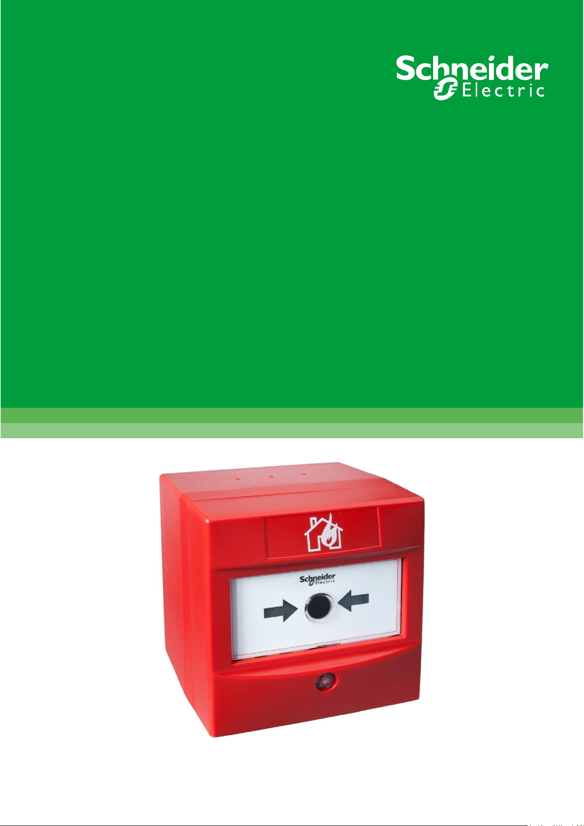
Manual Call Point
ECE221-I
Instruction Sheet
R10200GB0

2 R10200GB0
Schneider Electric Fire & Security Oy
Sokerilinnantie 11 C
FI-02600 Espoo, Finland
Tel: +358 10 446 511
Website: www.se.com
Document number: R10200GB0
Published: 05.03.2020
© 2020 – Schneider Electric. All Rights Reserved. This information is only to be used as guidance. Subject to changes and errors.

Contents
R10200GB0 3
Contents
1 Manual Call Point ECE221-I with isolator ............................................ 4
1.1 Operating Principles ..................................................................................................................... 4

1 Manual Call Point ECE221-I with isolator
4 R10200GB0
1 Manual Call Point ECE221-I with isolator
The Essentia intelligent manual call point ECE221-I (FFS06720318) with isolator has
been designed to operate on a loop of intelligent fire detection devices. An alarm is
initiated by pressing the resettable element. It´s suitable for semi flush or surface
mounting. An alarm status is indicated through the rotation of the resettable element,
displaying yellow and black indication bars and a solid red LED. The manual call point
can be easily reset from the front using the supplied reset key. There is a DIL switch for
address setting. Address range is 1-126.
• Resettable operating element
• Easy access, front reset mechanism
• E-Z fit connector system for installation
• Ergonomic reset key
• EN 54-11 & EN 54-17 certified
• 170-degree viewable LED
• Continuity link for cable insulation testing
• Suitable for semi flush or surface mounting
1.1 Operating Principles
The address of each call point is set at the commissioning stage by means of a DIL
switch.
A solid red alarm LED is provided on the manual call point. This LED is controlled
independently of the call point, by the control panel. The LED will flash yellow if there is a
fault and flash green when the device is polled.
Once activated, the Intelligent Manual Call Point can be reset by inserting the reset key
into the front facing LED, turning clockwise until a positive click and reset occurs.
The Intelligent Manual Call Point incorporates a short circuit isolator which will ensure its
operation in the event of a short circuit fault on the loop. Isolator operation is indicated by
a solid yellow LED.
This manual call point helps reduce installation time as all the initial installation cabling is
wired to a removable terminal block which fits neatly in the back of the manual call point.
The component parts of the call point are molded in a robust fire-retardant polycarbonate.

1 Manual Call Point ECE221-I with isolator
R10200GB0 5
Protocol Usage
Output Bits
2
Red LED
1
Electronic Self Test
0
Not Used
Yes
Analogue Value
16
Quiescent
64
Alarm
4
General Fault
1
Switch Fault
Input Bits
2
LED Confirmed
1
0=Alarm 1= Quiescent
0
1=Alarm 0= Quiescent
Flag Settings
XP95 Flag
Yes
Alarm Flag
No

1 Manual Call Point ECE221-I with isolator
6 R10200GB0
 Loading...