


 Loading...
Altivar 21
Variable speed drives for asynchronous motors
Programming Manual
Software V1.9
09/2009
AAV75193
www.schneider-electric.com

Contents
Important information __________________________________________________________________________________________ 5
Before You Begin _____________________________________________________________________________________________ 6
Documentation structure________________________________________________________________________________________ 8
Installation Manual ______________________________________________________________________________________ 8 Programming Manual ____________________________________________________________________________________ 8 Manuals for Modbus, Lonworks, BACnet, Metasys N2, Apogee FLN _______________________________________________ 8
Software enhancements________________________________________________________________________________________ 9
Enhancements made to version V1.1 in comparison to V1.0 _____________________________________________________ 9 Enhancements made to version V1.2 in comparison to V1.1 _____________________________________________________ 9 Enhancements made to version V1.3 in comparison to V1.2 _____________________________________________________ 9 Enhancements made to version V1.6 in comparison to V1.3 _____________________________________________________ 9 Enhancements made to version V1.7 in comparison to V1.6 _____________________________________________________ 9 Enhancements made to version V1.8 in comparison to V1.7 _____________________________________________________ 9 Enhancements made to version V1.9 in comparison to V1.8 _____________________________________________________ 9
Steps for setting up the drive ___________________________________________________________________________________ 10
Factory configuration _________________________________________________________________________________________ 11
Setup – Preliminary recommendations____________________________________________________________________________ 12
Power switching via line contactor _________________________________________________________________________ 12 User adjustment and extension of functions _________________________________________________________________ 12 Test on a low power motor or without a motor ________________________________________________________________ 13 Using motors in parallel _________________________________________________________________________________ 13 Using in single phase supply _____________________________________________________________________________ 13
Graphic display terminal _______________________________________________________________________________________ 14
Graphic display terminal features _________________________________________________________________________ 14 Graphic display terminal modes __________________________________________________________________________ 15 Monitoring Mode ______________________________________________________________________________________ 15 Run Mode ___________________________________________________________________________________________ 19 Programming Mode ____________________________________________________________________________________ 19
Menu Structure ______________________________________________________________________________________________ 20
Menu Navigation_______________________________________________________________________________________ 20 Submenus____________________________________________________________________________________________ 22 Accessing and Changing Parameters ______________________________________________________________________ 22
Common control schemes _____________________________________________________________________________________ 24
2-wire control _________________________________________________________________________________________ 24
3-wire control _________________________________________________________________________________________ 25 External speed control potentiometer ______________________________________________________________________ 26 4-20 mA speed control __________________________________________________________________________________ 26 Preset speeds (up to seven) _____________________________________________________________________________ 27 Serial communication __________________________________________________________________________________ 28 Forced local __________________________________________________________________________________________ 28 PID control ___________________________________________________________________________________________ 29
Drive Operation______________________________________________________________________________________________ 30
Local and Remote Modes of Operation _____________________________________________________________________ 30 Local Mode __________________________________________________________________________________________ 33 Resetting drive Faults in Local Mode _______________________________________________________________________ 33 Logic Input Functions Active in Local Mode _________________________________________________________________ 34 Remote Mode ________________________________________________________________________________________ 34
Quick Start _________________________________________________________________________________________________ 37
Quick menu AUF ______________________________________________________________________________________ 37 Motor parameters _____________________________________________________________________________________ 40
Programming Parameters______________________________________________________________________________________ 41
Parameter Reset (tYP) _________________________________________________________________________________ 41 Macro Programming (AU4) ______________________________________________________________________________ 42 Parameter Lock (F700) _________________________________________________________________________________ 43 Display of Submenu AUF (F738) __________________________________________________________________________ 43
AAV75193 09/20009 |
3 |

Contents
Motor Control Parameters _____________________________________________________________________________________ 44
Motor Control Mode (Pt) ________________________________________________________________________________ 44 Motor Tuning _________________________________________________________________________________________ 48 Auto-tuning __________________________________________________________________________________________ 49 Supply Voltage Correction and Motor Voltage Limitation (F307) __________________________________________________ 51 Motor 2 Control Parameters _____________________________________________________________________________ 52
Drive Control Parameters ______________________________________________________________________________________ 54
Application Parameters________________________________________________________________________________________ 59
Skip Frequencies ______________________________________________________________________________________ 65 DC Injection Braking Parameters _________________________________________________________________________ 66
I/O Control Parameters________________________________________________________________________________________ 67
Logic Input Function Compatibility _________________________________________________________________________ 71 Relay Output Functions _________________________________________________________________________________ 72 Analog Input Functions__________________________________________________________________________________ 78 Analog Output Functions ________________________________________________________________________________ 79 Logic Inputs Function ___________________________________________________________________________________ 80 Analog Input Adjustments (F201–F204; F160-F163; F210–F213; F470–F473)_______________________________________ 81 Always Active Logic Function ____________________________________________________________________________ 89 Preset Speeds (Sr1 – Sr7) _______________________________________________________________________________ 90 +/- Speed Control Parameters ____________________________________________________________________________ 91
Display Parameters __________________________________________________________________________________________ 94
Fault Management Parameters _________________________________________________________________________________ 97
Catch On The Fly (F301) ________________________________________________________________________________ 99 Overtorque Detection __________________________________________________________________________________ 105 Nuisance Overvoltage And Input Phase Fault Avoidance ______________________________________________________ 106 Motor Overload Characteristics (OLN) ____________________________________________________________________ 107
Serial Communication Parameters ______________________________________________________________________________ 109
Start/Stop Control By Speed Reference Level _____________________________________________________________________ 114
Droop Control ______________________________________________________________________________________________ 115
Permanent Magnet Motor_____________________________________________________________________________________ 116
Options ___________________________________________________________________________________________________ 117
Faults - Causes - Remedies ___________________________________________________________________________________ 118
Fault Conditions ______________________________________________________________________________________ 118 Alarm Conditions _____________________________________________________________________________________ 121 Pre-alarm Conditions __________________________________________________________________________________ 122 Resetting the drive after a Fault Condition __________________________________________________________________ 122
Parameters reset tables ______________________________________________________________________________________ 123
Parameter Reset _____________________________________________________________________________________ 123 Parameter values that do not vary by reset type _____________________________________________________________ 123 Parameter values that vary according to reset type ___________________________________________________________ 128 Parameter values that vary according to drive model, but not reset type___________________________________________ 128 Parameter values that vary according to drive model and reset type______________________________________________ 130 Parameter values that do not change if reset ________________________________________________________________ 131
User settings tables _________________________________________________________________________________________ 132
4 |
AAV75193 09/20009 |
Important information
PLEASE NOTE
Please read these instructions carefully and examine the equipment in order to familiarize yourself with the device before installing, operating or carrying out any maintenance work on it.
The following special messages that you will come across in this document or on the device are designed to warn you about potential risks or draw your attention to information that will clarify or simplify a procedure.
The addition of this symbol to a “Danger” or “Warning” safety label indicates that there is an electrical risk that will result in injury if the instructions are not followed.
This is a safety warning symbol. It warns you of the potential risk of injury. You must comply with all safety messages that follow this symbol in order to avoid the risk of injury or death.

 DANGER
DANGER indicates an imminently hazardous situation which, if not avoided, will result in death, serious injury or equipment damage.
 WARNING
WARNING indicates a potentially hazardous situation which, if not avoided, can result in death, serious injury or equipment damage.
 CAUTION
CAUTION indicates a potentially hazardous situation which, if not avoided, can result in injury or equipment damage.
PLEASE NOTE:
Only qualified personnel are authorized to carry out maintenance work on electrical equipment. Schneider Electric accepts no responsibility for the consequences of using this device. This document does not constitute an instruction manual for inexperienced personnel.
© 2008 Schneider Electric. All rights reserved.
AAV75193 09/20009 |
5 |

Before You Begin
Read and understand these instructions before performing any procedure with this drive.

 DANGER
HAZARD OF ELECTRIC SHOCK, EXPLOSION, OR ARC FLASH
•Read and understand this manual before installing or operating the Altivar 21 drive. Installation, adjustment, repair, and maintenance must be performed by qualified personnel.
•The user is responsible for compliance with all international and national electrical code requirements with respect to grounding of all equipment.
•Many parts of this drive, including the printed circuit boards, operate at the line voltage. DO NOT TOUCH. Use only electrically insulated tools.
•DO NOT touch unshielded components or terminal strip screw connections with voltage present.
•DO NOT short across terminals PA/+ and PC/– or across the DC bus capacitors.
•Before servicing the drive:
—Disconnect all power.
—Place a “DO NOT TURN ON” label on all power disconnects.
—Lock all power disconnects in the open position.
—Disconnect all power, including external control power that may be present, before servicing the drive. WAIT
15 MINUTES to allow the DC bus capacitors to discharge. Then follow the “Bus Voltage Measurement Procedure” located in the Installation Manual, to verify that the DC voltage is less than 42 V. The drive LED is not an indicator of the absence of DC bus voltage.
•Install and close all covers before applying power or starting and stopping the drive.
Failure to follow these instructions will result in death or serious injury.


 DANGER
UNINTENDED EQUIPMENT OPERATION
Before turning on the drive or upon exiting the configuration menus, ensure that the inputs assigned to the Run command are in a state that will not cause the drive to run. Otherwise, the motor can start immediately.
Failure to follow this instruction will result in death, serious injury, or equipment damage.


 DANGER
UNINTENDED EQUIPMENT OPERATION
•Prevent accidental grounding of logic inputs configured for sink logic. Accidental grounding can result in unintended activation of drive functions.
•Protect the signal conductors against damage that could result in unintentional conductor grounding.
Failure to follow these instructions will result in death or serious injury.
6 |
AAV75193 09/20009 |

Before You Begin
 WARNING
LOSS OF CONTROL
•The designer of any control scheme must consider the potential failure modes of control paths and, for certain critical control functions, provide a means to achieve a safe state during and after a path failure. Examples of critical control functions are emergency stop and overtravel stop.
•Separate or redundant control paths must be provided for critical control functions.
•System control paths may include communication links. Consideration must be given to the implications of unanticipated transmission delays or failures.
•Each implementation of an Altivar 21 drive must be individually and thoroughly tested for proper operation before being placed into service.
Failure to follow these instructions can result in death, serious injury, or equipment damage.
 WARNING
LOSS OF CONTROL
•Set the communication error trip time to stop the drive in case the remote graphic display terminal display is deactivated by an unusual event such as tripping, an operation error, or a power outage.
•Ensure that the communication error trip time is properly set before deactivating the remote graphic display terminal display.
Failure to follow these instructions can result in death, serious injury, or equipment damage.
AAV75193 09/20009 |
7 |

Documentation structure
The following Altivar 21 technical documents are available on the Telemecanique website (www.telemecanique.com) as well as on the CD-ROM supplied with the drive.
Installation Manual
This manual contains complete mounting and wiring instructions.
Programming Manual
This describes the functions, parameters and use of the drive terminal (integrated display terminal and graphic display terminal). The communication functions are not described in this manual, but in the manual for the bus or network used.
Manuals for Modbus, Lonworks, BACnet, Metasys N2, Apogee FLN
These manuals describe the assembly, connection to the bus or network, signaling, diagnostics, and configuration of the communication-specific parameters via the integrated display terminal or the graphic display terminal.
They also describe the communication services of the protocols.
8 |
AAV75193 09/20009 |

Software enhancements
Since the Altivar ATV21 was first launched, it has benefited from the addition of several new functions. The software version is now V1.9. The old versions can be replaced by this new one without any modifications.
Although this documentation relates to version V1.9, it can still be used with earlier versions, as the updates merely involve the addition of new values and parameters, and none of the parameters of the previous versions have been modified or removed.
The software version is indicated on the nameplate attached to the body of the drive.
Enhancements made to version V1.1 in comparison to V1.0
•New factory value for Supply Voltage Correction and Motor Voltage Limitation F307 = Supply Voltage Corrected - motor voltage unlimited (F307 = 3). See page 51.
•Modify factory value for Motor No-load Current F416 = According to drive model. See page 48.
•New factory value for FL Relay Function F132 = Inversion of fault relay (F132 = 11). See page 85.
•No detection of Ground Fault EF2 during Line supply undervoltage fault MOFF over 22 kW product.
Enhancements made to version V1.2 in comparison to V1.1
•New factory value for Motor Current Limit F601 = 110 % of the drive’s output current rating. See page 47.
•New factory value for Motor 2 Current Limit F185 = 110 % of the drive’s output current rating. See page 52.
•In case of Supply Voltage Correction and Motor Voltage Limitation F307 = Supply voltage uncorrected (F307 = 0 or 2), auto-swap the Motor rated voltage ulu as 200 V (200 V range) or 400 V (400 V range). See page 51 and page 40.
Enhancements made to version V1.3 in comparison to V1.2
• New factory value for Time-out F803 = 3 seconds of the drive’s output current rating. See page 110.
Enhancements made to version V1.6 in comparison to V1.3
•New factory value for Auto Fault Reset F303 = Disabled (F303 = 0). See page 97.
•Overvoltage Fault OPx is automatically re-start when Auto Fault Reset F303 = Disabled (F303 = 0). See page 120and page 97.
•New factory value for Disabling of graphic display terminal Fault Reset Function F735 = Disabled (F735 = 1). See page 58.
•Improvement of speed search function.
•Modify external keypad interface (text on "Stop" button becomes "Stop / Reset").
•Stop key from optional graphic display terminal (VW3A21101).
Enhancements made to version V1.7 in comparison to V1.6
•New parameter Power supply adjustment gain F484. See page 106.
•Clear PID integral value (function 65) and PID Control Prohibited (function 14) are valid for all Remote Mode Start/Stop Control CMOd adjustment.
Enhancements made to version V1.8 in comparison to V1.7
• Improvement countermesure of vibration issue (F484). See page 106.
Enhancements made to version V1.9 in comparison to V1.8
New parameters:
•Delay for RY-RC Relay F146. See page 85.
•Delay for FL Relay F147. See page 85.
•Threshold logic for relay link to VIA F160. See page 81.
•Hysteresis threshold for logic relay link to VIA F161. See page 81.
•Threshold logic for relay link to VIB F162. See page 81.
•Hysteresis threshold for logic relay link to VIB F163. See page 81.
•PI regulator reversal direction correction F380. See page 87.
•Stop on LL hysteresis F391. See page 87.
•PI wake up threshold on PI error F392. See page 87.
•PI wake up threshold on PI feedback error F393. See page 87.
•Drive behaviour on 4-20 event F644. See page 104.
•Fallback speed F649. See page 104.
•Low frequency when analog output equal 0 V F694. See page 84.
•High frequency when analog output equal 0 V F695. See page 84.
AAV75193 09/20009 |
9 |

Steps for setting up the drive
INSTALLATION
v 1 Consult the Installation Manual
PROGRAMMING
Tips:
•Before you start programming, complete the user setting tables, page
132.
•Perform an auto-tuning operation to optimize performance, page 48.
•If you get lost, return to the factory settings, page 123.
Note: Check that the wiring of the drive is compatible with its configuration.
b 2 Configure the parameters
v Quick menu AUF v Motor parameters
v Perform an auto-tuning operation
b 3 Start
10 |
AAV75193 09/20009 |
Factory configuration
Drive factory settings
The Altivar 21 is factory-set for the most common operating conditions:
•Motor Control Mode Pt : Variable torque (Pt = 1). See page 45.
•High speed UL = 50.0 Hz. See page 59.
•Low speed LL = 0.0 Hz. See page 59.
•Switching Frequency Level F300: depending on drive rating (see page 64)
•Auto Ramp Adaptation AU1 = Enabled (AU1 = 1). See page 64.
Parameter which depends on Macro Programming AU4 = Factory setting 0 (see page 42):
•Command reference: logic inputs (CNOd = 0). See Remote Mode Start/Stop Control page 54.
•Speed reference: analog input VIA = 0–10 V or 0–20 mA (FNOd = 1, F201 = 0). See Remote Mode Primary Speed Reference Source FMOD page 54 and Analog Input Speed Reference page 81.
•F: run forward (F111 = 2). See F Logic Input Function page 80.
•R: preset speed 1 (F112 = 6). See R Logic Input Function page 80.
•RES: fault reset (F113 = 10). See RES Logic Input Function page 80.
•Drive ready for operation (F110 = 1). See Always Active Logic Function 2 page 89.
If the above values are compatible with the application, the drive can be used without changing the settings.
AAV75193 09/20009 |
11 |

Setup – Preliminary recommendations
 CAUTION
INCOMPATIBLE LINE VOLTAGE
Before turning on and configuring the drive, ensure that the line voltage is compatible with the supply voltage range shown on the drive nameplate. The drive may be damaged if the line voltage is not compatible.
Failure to follow these instructions can result in equipment damage.
Power switching via line contactor
 CAUTION
UNINTENDED EQUIPMENT OPERATION
•Avoid operating the contactor frequently (premature ageing of the filter capacitors).
•Cycle times < 60 s may result in damage to the pre-charge resistor.
Failure to follow these instructions can result in equipment damage.
User adjustment and extension of functions
•The display unit and buttons can be used to modify the settings and to extend the functions described in the following pages.
•Return to factory settings is made easy by the Parameter Reset tYP (see page 41).
DANGER
UNINTENDED EQUIPMENT OPERATION
•Check that changes made to the settings during operation do not present any danger.
•We recommend stopping the drive before making any changes.
Failure to follow these instructions will result in death or serious injury.
12 |
AAV75193 09/20009 |

Setup – Preliminary recommendations
Test on a low power motor or without a motor
•In factory settings mode, Output Phase Failure Detection Mode F605 (see page 102) is active (F605 = 3). To check the drive in a test or maintenance environment without having to switch to a motor with the same rating as the drive (particularly useful in the case of high power drives), deactivate F605 = 0.
•Set Motor Control Mode Pt = Constant V/Hz 0 (see page 45)
 CAUTION
UNINTENDED EQUIPMENT OPERATION
Motor thermal protection will not be provided by the drive if the motor current is less than 0.2 times the rated drive current. Provide an alternative means of thermal protection.
Failure to follow these instructions can result in equipment damage.
Using motors in parallel
• Set Motor Control Mode Pt = Constant V/Hz 0 (see page 45).
 CAUTION
UNINTENDED EQUIPMENT OPERATION
Motor thermal protection is no longer provided by the drive. Provide an alternative means of thermal protection on every motor.
Failure to follow these instructions can result in equipment damage.
Using in single phase supply
• Set Input Phase Failure Detection Mode F608 = Disabled 0 (see page 100).
 CAUTION
UNINTENDED EQUIPMENT OPERATION
Using ATV21 in single phase supply is only allowed in training mode with motor and without load.
Failure to follow these instructions can result in equipment damage.
AAV75193 09/20009 |
13 |
Graphic display terminal
This section describes the features of the integrated graphic display terminal display. An optional graphic display terminal (VW3A21101) is also available.
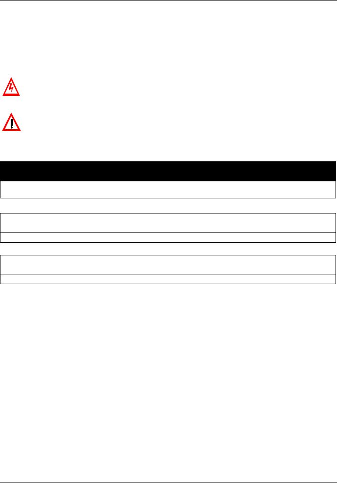
Graphic display terminal features
1
2
|
RUN |
% |
|
3 |
PRG |
||
Hz |
|||
MON |
|||
|
|
Loc
Rem
6
7
RUN STOP
12
13
4
5
8
9
 10
10
 11
11
 14
14
|
LED/Key |
Characteristics |
||
1 |
Display RUN LED |
• |
Illuminates when a run command is applied to the drive. |
|
• |
Flashes when there is a speed reference present with a Run command. |
|||
|
|
|||
|
|
|
|
|
2 |
Display PRG LED |
• |
Illuminates when Programming mode is active. |
|
• |
Flashes in AUF, GrU modes |
|||
|
|
|||
|
|
|
|
|
3 |
Display MON LED |
• |
Illuminates when Monitoring mode is active. |
|
• |
Flashes in fault history display mode |
|||
|
|
|||
|
|
|
||
4 |
Display unit |
4 digits, 7 segments |
||
|
|
|
|
|
5 |
Display unit LED |
• |
The % LED illuminates when a displayed numeric value is a percentage. |
|
• |
The Hz LED illuminates when a displayed numeric value is in hertz. |
|||
|
|
|||
|
|
|
||
|
|
Depending on the mode, you can use the arrows to: |
||
6 |
UP/DOWN keys |
• |
Navigate between the menus |
|
• |
Change a value |
|||
|
|
|||
|
|
• |
Change the speed reference when the UP/DOWN LED (7) is illuminated |
|
|
|
|
||
7 |
UP/DOWN LED |
Illuminates when the navigation arrows are controlling the speed reference |
||
|
|
|
||
8 |
Loc/Rem LED |
Illuminates when Local mode is selected |
||
|
|
|
||
|
|
Press to select the graphic display terminal mode. |
||
|
|
• |
Run mode (default on power-up) |
|
9 |
MODE |
• Programming mode |
||
|
|
• |
Monitoring mode |
|
|
|
Can also be used to go back to the previous menu. |
||
|
|
|
||
10 |
Loc/Rem |
Switches between Local and Remote modes |
||
|
|
|
||
11 |
ENT |
Press to display a parameter’s value or to save a changed value. |
||
|
|
|
||
12 |
RUN LED |
Illuminates when the Run key is enabled |
||
|
|
|
||
13 |
RUN |
Pressing this key when the RUN LED is illuminated starts the drive. |
||
|
|
|
||
|
|
Stop/reset key. |
||
|
|
In Local mode, pressing the STOP key causes the drive to stop based on the setting of parameter |
||
|
|
F721. |
||
14 |
STOP |
In Remote mode, pressing the STOP key causes the drive to stop based on the setting of parameter |
||
|
|
F603. The display will indicate a flashing “E”. |
||
|
|
If F735 is set to 0 (default setting), pressing the stop key twice will reset all resettable faults if the fault |
||
|
|
condition has been resolved. |
||
|
|
|
|
|
14 |
AAV75193 09/20009 |
Graphic display terminal
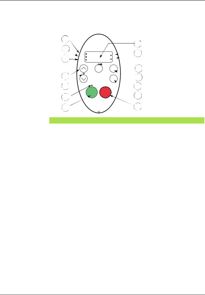
Graphic display terminal modes
The Altivar 21 graphic display terminal has three modes of operation: Monitoring, Run and Programming. The drive powers up in the Run mode. To select a different mode, use the MODE key as illustrated below.
ATV21 drive |
|
|
|
|
|
|
|
|
|
|
|
|
|
|
|
|
Power Up |
|
|
Run |
Programming |
|
|
|
Monitoring |
||||||||
|
|
|
|
|
|
|
||||||||||
|
|
RUN |
mode |
PROG |
mode |
MODE |
|
|
mode |
|||||||
|
|
|
|
|||||||||||||
|
|
|
|
|
|
|
|
|
|
|
|
|
|
|||
|
|
0.0 |
|
AUF |
|
|
|
|
Fr-F |
|
|
|
|
|||
|
|
|
|
|
|
|
|
|
|
|
|
|
||||
|
|
|
|
|
Hz |
|
|
|
|
MON |
|
|
|
|
MODE Key |
|
|
|
|
|
|
|
|
|
|
|
|
|
|
||||
|
|
|
|
|
|
|
|
|
|
|
|
|
|
|
||
|
|
|
|
|
|
|
|
|
|
|
|
|
|
|
|
|
Monitoring Mode
The Monitoring mode displays drive operational data in real time. To access the Monitoring mode, press the MODE key until the MON LED is illuminated. Then use the UP and DOWN keys to view up to 30 different types of data.
Mode key
C80
|
|
|
|
|
Up/Down keys |
PROG |
AUF |
|
|
|
|
|
|
|
|
|
|
|
|
|
|
|
|
F60.0
Fr-F
MON
25 other parameters
t0.10
RUN
0.0
n---
AAV75193 09/20009 |
15 |

Graphic display terminal
Monitoring Mode Displays
Display |
Name |
Description |
|
|
|
|||
Fr-F |
Direction of rotation |
Fr-F = forward direction |
||||||
|
Fr-r = reverse direction |
|||||||
|
|
|||||||
|
|
|
|
|
|
|
||
F 60.0 |
Speed reference |
Command frequency to drive, displayed either as Hz or in custom unit set by parameter F702 |
||||||
|
|
|
|
|
|
|
||
C 80 |
Motor current |
The average of the 3 phases of motor current displayed either as amperes or as a percentage of the |
||||||
|
drive's nameplate-rated output current. Select % or A with parameter F701. |
|||||||
|
|
|||||||
|
|
|
|
|
|
|
||
Y 100 |
Line voltage |
The average of the 3 phases of line to line input voltages displayed either in volts or as a percentage |
||||||
|
of the drive's rated input voltage (200 V for 208/240 V models - 400 V for 480 V models). Select % or |
|||||||
|
|
|||||||
|
|
volts with parameter F701. |
||||||
|
|
|
|
|
|
|
||
P 100 |
Motor voltage |
The average of the 3 phases of line to line output voltages displayed either in volts or as a percentage |
||||||
|
of the drive's rated output voltage (200 V for 208/240 V models - 400 V for 480 V models). Select % |
|||||||
|
|
|||||||
|
|
or volts with parameter F701. |
||||||
|
|
|
|
|
|
|
||
q 60 |
Motor torque |
Estimated motor torque as a percentage of the motor's rated torque |
||||||
|
|
|
|
|
|
|
||
c 90 |
Torque current |
The average of the 3 phases of torque-producing motor current displayed either as amperes or as a |
||||||
|
percentage of the motor's rated torque-producing current. Select % or A with parameter F701. |
|||||||
|
|
|||||||
|
|
|
|
|
|
|
||
L 70 |
drive load factor |
The motor current as a percentage of the drive's rated output current, which may be reduced from the |
||||||
|
drive’s nameplate current rating by adjustments in switching frequency. |
|||||||
|
|
|||||||
|
|
|
|
|
|
|
||
h 80 |
Input power |
drive input power displayed in kilowatts (kW) |
||||||
|
|
|
|
|
|
|
||
H 75 |
Output power |
drive output power displayed in kilowatts (kW) |
||||||
|
|
|
|
|
|
|
||
o 60.0 |
Motor operating |
Motor operating frequency, displayed either as Hz or in custom unit set by parameter F702 |
||||||
|
frequency |
|
|
|
|
|
|
|
. .11 |
Logic input map |
ON: |
|
|
|
|
The bar representing VIA is displayed only if F109 = 1 or 2 |
|
|
|
|
|
|||||
|
|
|
|
|
|
|||
|
|
OFF: |
|
|
|
|
|
|
|
|
VIA |
|
F |
||||
|
|
|
|
|
|
R |
||
|
|
|
|
|
|
RES |
||
|
|
|
|
|
|
|
|
|
0.1 |
Relay output map |
ON: |
|
|
|
|
||
|
|
|
|
|||||
|
OFF: |
|
|
|
|
|||
|
|
|
|
|
|
|||
|
|
|
|
|
|
|
||
|
|
|
|
FL |
RY-RC |
|||
|
|
|
|
|
|
|
|
|
u 101 |
CPU 1 version |
Version of CPU 1 |
|
|
|
|||
|
|
|
|
|
|
|
|
|
u c01 |
CPU 2 version |
Version of CPU 2 |
|
|
|
|||
|
|
|
|
|
|
|
|
|
uE01 |
Memory version |
Version of memory |
|
|
|
|||
|
|
|
|
|
|
|
||
d 50 |
PID feedback |
Level of PID feedback, displayed either as Hz or in custom unit set by parameter F702 |
||||||
|
|
|
|
|
|
|
||
b 70 |
PID computed |
Speed reference command to drive as computed by the PID function, displayed either as Hz or in |
||||||
speed reference |
custom unit set by parameter F702 |
|||||||
|
||||||||
|
|
|
|
|
|
|
|
|
h 85 |
Accumulated input |
|
|
|
|
|
|
|
power |
Accumulated input power consumed by the drive displayed in kWh |
|||||||
|
||||||||
|
consumption |
|
|
|
|
|
|
|
|
|
|
|
|
|
|
|
|
H 75 |
Accumulated |
|
|
|
|
|
|
|
output power |
Accumulated output power supplied by the drive displayed in kWh |
|||||||
|
||||||||
|
consumption |
|
|
|
|
|
|
|
|
|
|
|
|
|
|
||
A 16.5 |
Drive rated output |
Drive nameplate rated output current in amperes |
||||||
|
current |
|
|
|
|
|
|
|
1500 |
Motor speed |
Motor speed in rpm |
|
|
|
|||
|
|
|
|
|
|
|
|
|
16 |
AAV75193 09/20009 |

Graphic display terminal
Monitoring Mode Displays (continued)
Display |
Name |
Description |
|
|
||
N 50 |
Communication |
Displays the counter numbers of communication through the network |
||||
counter |
||||||
|
|
|
|
|
||
|
|
|
|
|
||
n 50 |
Normal state |
Displays the counter numbers of communication only at normal state in all communication through the |
||||
|
network |
|
|
|||
|
|
|
|
|||
|
|
|
|
|
||
OC3 1 |
Past fault 1 |
The most recent fault stored in the fault history. If the drive is in a fault state, this is not the active fault. |
||||
|
A fault is stored in the fault history after it is cleared by fault reset action. Press ENT to review drive |
|||||
|
|
|||||
|
|
state at time of fault. See “Fault Display and History” on page 18 and “Faults - Causes - Remedies” on |
||||
|
|
page 118 for more detail. |
||||
|
|
|
|
|
||
OH 2 |
Past fault 2 |
Second most recent fault. |
||||
|
|
|
|
|
||
OP3 3 |
Past fault 3 |
Third most recent fault. |
||||
|
|
|
|
|
|
|
nErr |
Past fault 4 |
Fourth most recent fault. |
||||
4 |
|
|||||
|
|
|
|
|
||
|
|
|
|
|
|
|
N ...1 |
Drive service alarm |
ON: |
|
|
||
|
|
OFF: |
|
|
||
|
|
|
|
|
||
|
|
|
|
|
|
|
|
|
Cumulative |
Cooling fan |
|||
|
|
Operation |
Main Control board |
|||
|
|
Time |
DC Bus capacitor |
|||
|
|
|
|
|
||
t0.10 |
Drive run time |
Cumulative drive run time. 0.01 = 1 hour. |
||||
|
1.00 = 100 hours |
|
|
|||
|
|
|
|
|||
|
|
|
|
|
|
|
AAV75193 09/20009 |
17 |

Graphic display terminal
Fault Display and History
When the drive faults, the graphic terminal displays a fault code. To review data about drive operation at the time of the fault, press the MODE key to enter the Monitoring mode. Then use the Up/Down keys to scroll through the data listed in table page 16.
Up to five faults can be displayed on the graphic terminal in Monitoring mode: the present fault (if the drive is in a fault state) and the previous four faults. To review drive operation data recorded at the time of fault for a previous fault, press ENT when the code for the fault is displayed. See table below for the available information.
When a fault is reset or power is cycled to the drive, the present fault becomes Past Fault 1.
Fault History
Display |
Name |
|
|
|
|
Description |
|
n 2 |
Fault counter |
Number of times in succession that this particular fault has occurred |
|||||
|
|
|
|
|
|
||
o 60.0 |
Motor operating |
Motor operating frequency, displayed either as Hz or in custom unit set by parameter F702 |
|||||
|
frequency |
|
|
|
|
|
|
Fr-F |
Direction of |
Fr-F = forward direction |
|||||
rotation |
Fr-r = reverse direction |
||||||
|
|||||||
|
|
|
|
|
|
||
F 60.0 |
Speed reference |
Command frequency to drive, displayed either as Hz or in custom unit set by parameter F702 |
|||||
|
|
|
|
|
|
||
C 80 |
Motor current |
The average of the 3 phases of motor current displayed either as A or as a percentage of the drive's |
|||||
nameplate-rated output current. Select % or A with parameter F701. |
|||||||
|
|
||||||
|
|
|
|
|
|
||
Y 100 |
|
The average of the 3 phases of line to line input voltages displayed either in volts or as a percentage of |
|||||
Line voltage |
the drive's rated input voltage (200 V for 208/240 V models - 400 V for 480V models). Select % or volts |
||||||
|
|||||||
|
|
with parameter F701. |
|
|
|||
|
|
|
|
|
|
||
P 100 |
|
The average of the 3 phases of line to line output voltages displayed either in volts or as a percentage |
|||||
Motor voltage |
of the drive's rated output voltage (200 V for 208/240 V models - 400 V for 480 V models). Select % or |
||||||
|
|||||||
|
|
volts with parameter F701. |
|||||
|
|
|
|
|
|
|
|
. .11 |
|
ON: |
|
|
The bar representing VIA is displayed only if |
||
|
|
|
|||||
|
|
|
|
F109 = 1 or 2 |
|||
|
Logic input map |
OFF: |
|
|
|||
|
VIA |
|
F |
||||
|
|
|
|
|
|
R |
|
|
|
|
|
|
|
RES |
|
|
|
|
|
|
|
|
|
0.1 |
|
ON: |
|
|
|
||
|
OFF: |
|
|
|
|
||
|
Relay output map |
|
|
|
|||
|
|
|
|
|
|
||
|
|
|
|
FL |
RY-RC |
||
|
|
|
|
|
|
||
t0.10 |
Drive run time |
Cumulative drive run time. 0.01 = 1 hour. 1.00 = 100 hours |
|||||
|
|
|
|
|
|
|
|
I/O Map
In both the monitoring mode and the fault history, it is possible to view the state of the logic inputs and the relay outputs. See previous tables on pages 16 and 18.
Logic Input Map
ON: |
|
|
OFF: |
|
|
VIA |
|
F |
|
|
R |
RES
The ON or OFF status of each logic input is displayed in bits. VIA is included in this display if parameter F109 is set to either 1 or 2.
Relay Output Map
ON: 
OFF:
FL RY-RC
The ON or OFF status of each relay output is displayed in bits.
18 |
AAV75193 09/20009 |

Graphic display terminal
Run Mode
To access the Run mode, press the MODE key until the drive operating frequency, a fault code, or a pre-alarm code is displayed. See Faults - Causes - Remedies beginning on page 118 for the fault and pre-alarm codes.
Changing the Display in Run Mode
Motor operating frequency is the default value displayed on the graphic terminal in Run mode. This displayed value can be changed by setting parameter Default graphic display terminal Operational Value F710. See page 94 for a list of the display choices.
The displayed value can be expressed as a percentage of the drive rating, or in amperes or volts, as appropriate for the value displayed. The units can be changed by setting parameter Graphic display terminal (% or A/V Units) F701 (see page 94).
In addition, the resolution of the speed reference and output frequency displays can be adjusted by setting parameters Local Mode Speed Reference Step Changes F707 and Graphic display terminal Frequency Resolution F708 (see pages 55 and 94).
Programming Mode
Use this mode to program the drive.
To access the Programming mode, use the MODE key until the PRG indicator LED on the display is illuminated.
AAV75193 09/20009 |
19 |
Menu Structure
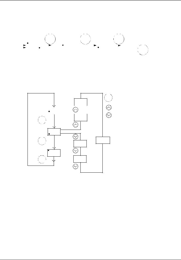
Menu Navigation
Menu navigation diagrams below and page 21 illustrate how to navigate through the programming menus and submenus.
Power |
|
RUN |
|
|
|
|
|
|
|
Up |
|
0.0 |
|
|
|
|
|
Hz |
|
|
Mode |
|
Mode |
ENT |
|
|
|
|
AUH |
|
|
|
|
Mode |
|
|
|
|
ENT |
MON |
Fr - F |
|
AUF |
|
|
|
PRG |
Mode |
|
Monitoring |
|
|
||
|
|
|
||
Mode |
|
|
Programming |
|
|
|
|
ENT |
|
|
|
Mode |
Mode |
GrU |
|
|
|
|
Mode |
Mode Mode Key
ENT ENT Key
UP/DOWN Key
ENT
F-- -- --
Mode
Sr 1...7 |
OLN |
tHr |
ub |
Pt |
uLu |
uL |
LL |
UL |
FH |
dEC |
ACC |
Fr |
tyP |
Fn |
FnSL |
FnOP |
CnoD |
AU4 |
AU1 |
a To Bottom
of List
b
c
d
Refer to diagram on next page for:
aLast Five Used Parameters
bFrequently Used Parameters
cChanges From Factory Setting
dAdditional Parameters
To Top
of List
20 |
AAV75193 09/20009 |

Menu Structure
Menu Navigation (continued)
a |
History parameters |
|
OLN |
|
ENT |
AUH |
* |
|
Mode |
|
* |
* |
* |
* |
LL |
b |
Quick menu |
HEAD |
ENT
AUF |
AU1 |
|
Mode
ACC
dEC
LL
UL |
tHr |
Fn |
Pt |
uL |
uLu |
END |
c |
User parameters |
|
1. Pressing the UP key |
||
|
|
|
|
|
|
|
|
|
|
|
searches the |
|
|
|
|
|
parameter list |
|
|
|
|
|
starting with the first |
|
|
|
|
||
|
|
|
|
|
one changed. |
|
|
|
|
|
|
|
U -- -- F |
|
|
|
|
2. |
Pressing the DOWN |
4 |
3 |
|
key searches the |
|
|
|
parameter list |
1 |
U -- -- F |
|
starting with the last |
|
one changed. |
||
|
|
|
|
|
3 |
3. |
The number of |
|
|
|
parameters |
1 |
U -- -- F |
|
displayed within the |
|
GrU menu |
||
ENT |
|
|
|
|
|
depends upon how |
|
|
U -- -- -- |
|
|
GrU |
|
many have been |
|
|
|
|
|
Mode |
|
|
altered from their |
2 |
U -- -- r |
|
factory settings. |
|
3 |
4. |
When all the |
|
|
changed parameters |
|
|
|
|
|
|
|
|
have been displayed, |
2 |
U -- -- r |
|
the display returns to |
|
|
|
GrU. |
3 |
2 |
U -- -- r |
d Extended parameters
* |
To Bottom |
|
of List |
F102 |
F101 |
ENT
F-- -- -- |
F100 |
|
Mode |
|
F912 |
|
F911 |
|
To Top |
|
of List |
|
* |
AAV75193 09/20009 |
21 |

Menu Structure
Submenus
The ATV21 drive features 4 submenus (see diagram on page 21) that are designed to reduce the time and effort required to program application parameters. Parameters can be modified within these submenus.
AUH: History Parameters
The AUH submenu displays, in reverse chronological order, the last 5 parameters that have been changed from their factory settings. Each time the AUH submenu is accessed, it searches for the latest parameters changed from their factory settings. If all parameters are at their factory settings, no display is generated.
Parameter Lock F700 is not displayed in the AUH menu, even if its value has been changed (see page 43).
AUF: Quick Menu
The AUF submenu provides ready access to the ten basic parameters commonly used in programming the drive. In many cases, programming the ATV21 drive is complete when these 10 parameters have been properly set (see chapter Quick Menu page 37).
GrU: User Parameters
The GrU submenu displays all parameters that have been changed from their factory settings. Each time the GrU submenu is accessed, its content is refreshed with the latest list of parameters changed from their factory settings. If all parameters are at their factory setting, no display is generated.
Parameters Fn and F470 – F473 are not displayed in the GrU menu, even if their values have been changed.
F– – –: Extended Parameters
The extended parameter submenu provides access to parameters used for special settings and applications.
Accessing and Changing Parameters
The diagram below illustrates how to access and change parameter values.
|
|
ENT |
1 |
AUF |
AU1 |
|
ENT |
ACC |
10.0 |
|
ENT |
|
3.0 |
2 |
Save Change |
Discard
Changes
Mode
22 |
AAV75193 09/20009 |

Menu Structure
Parameters that cannot be changed while the drive is running
The table below lists the parameters that cannot be changed unless the drive is stopped (displaying 0.0 or OFF on the graphic display terminal).
Parameter |
Description |
|
AU1 |
Auto ramp adaptation |
|
|
|
|
AU4 |
Macro programming |
|
|
|
|
CNOd |
Remote mode start/stop control source |
|
|
|
|
FNOd |
Remote mode primary speed reference source |
|
|
|
|
tYp |
Parameter reset |
|
|
|
|
FH |
Maximum frequency |
|
|
|
|
uL |
Motor rated frequency |
|
|
|
|
uLu |
Motor rated voltage |
|
|
|
|
Pt |
Motor control mode |
|
|
|
|
F108 |
Always active logic function 1 |
|
|
|
|
F109 |
VIA input function (analog or logic selection) |
|
|
|
|
F110 |
Always active logic function 2 |
|
|
|
|
F111 |
F logic input function |
|
|
|
|
F112 |
R logic input function |
|
|
|
|
F113 |
RES logic input function |
|
|
|
|
F118 |
VIA logic input function |
|
|
|
|
F130 |
RY-RC relay primary function |
|
|
|
|
F132 |
FL relay function |
|
|
|
|
F137 |
RY-RC relay secondary function |
|
|
|
|
F139 |
RY-RC relay function logic selection |
|
|
|
|
F170 |
Motor 2 rated frequency |
|
|
|
|
F171 |
Motor 2 rated voltage |
|
|
|
|
F300 |
Switching frequency level |
|
|
|
|
F301 |
Catch on the fly |
|
|
|
|
F303 |
Auto fault reset |
|
|
|
|
F302 |
Coast to stop on loss of input power |
|
|
|
|
F305 |
Overvoltage fault protection |
|
|
|
|
F307 |
Supply voltage correction and motor voltage |
|
limitation |
||
|
||
|
|
|
F311 |
Motor rotation direction command |
|
|
|
Parameter |
Description |
|
F316 |
Switching frequency control mode |
|
|
|
|
F400 |
Auto tuning enable |
|
|
|
|
F415 |
Motor rated full load current |
|
|
|
|
F416 |
Motor no-load current |
|
|
|
|
F417 |
Motor rated speed |
|
|
|
|
F418 |
Frequency loop gain |
|
|
|
|
F419 |
Frequency loop stability |
|
|
|
|
F480 |
Magnetizing current coefficient |
|
|
|
|
F481 |
Line noise compensation filter |
|
|
|
|
F482 |
Line noise inhibitor filter |
|
|
|
|
F483 |
Line noise inhibitor gain |
|
|
|
|
F484 |
Power supply adjustment gain |
|
|
|
|
F485 |
Stall prevention control coefficient 1 |
|
|
|
|
F492 |
Stall prevention control coefficient 2 |
|
|
|
|
F494 |
Motor adjustment coefficient |
|
|
|
|
F495 |
Maximum voltage adjustment coefficient |
|
|
|
|
F496 |
Waveform switching adjustment coefficient |
|
|
|
|
F601 |
Motor current limit |
|
|
|
|
F603 |
External fault stop mode |
|
|
|
|
F605 |
Output phase failure detection mode |
|
|
|
|
F608 |
Input phase failure detection mode |
|
|
|
|
F613 |
Output short-circuit detection mode |
|
|
|
|
F626 |
Overvoltage fault operation level |
|
|
|
|
F627 |
Undervoltage fault operation mode |
|
|
|
|
F732 |
Disabling of graphic display terminal local/remote |
|
key |
||
|
||
|
|
|
F910 |
Permanent magnet motor step-out detection current |
|
level |
||
|
||
|
|
|
F911 |
Permanent magnet motor step-out detection time |
|
|
|
|
F912 |
Permanent magnet motor high-speed torque |
|
adjustment coefficient |
||
|
||
|
|
AAV75193 09/20009 |
23 |
Common control schemes
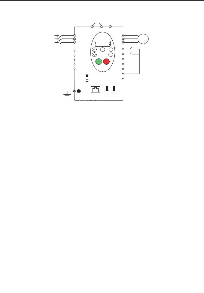
2-wire control
|
PO |
PA/+ |
|
PC/- |
|
|
|
|
R/L1 |
|
|
|
|
|
|
U/T1 |
|
S/L2 |
|
|
|
|
|
|
V/T2 |
M |
T/L3 |
|
|
|
|
|
|
W/T3 |
|
|
|
|
|
|
|
|
||
|
|
RUN |
|
|
% |
|
|
|
|
|
|
|
|
|
|
|
|
|
|
PRG |
|
|
|
|
|
|
|
|
MON |
|
|
Hz |
|
|
|
|
|
|
Loc |
|
MODE |
F |
|
Run forward |
FLC |
|
|
Rem |
|
|
|||
|
|
|
|
|
|
|
Run reverse |
|
FLB |
|
|
|
|
ENT |
R |
|
|
|
|
|
|
|
|
|
|
|
FLA |
|
|
|
|
|
RES |
|
|
|
|
|
|
|
|
|
|
|
|
|
RUN |
STOP |
|
|
|
|
|
RY |
|
|
|
|
|
FM |
|
|
RC |
SW4 |
|
|
|
|
CC |
|
|
|
|
|
|
|
|
|
||
|
SOURCE |
|
|
|
|
P24 |
|
|
|
|
|
|
|
|
|
|
|
PLC |
|
|
|
|
PLC |
|
|
|
|
SINK |
|
|
FM |
VIA |
|
|
|
|
|
|
V |
|
|
V |
|
|
|
|
|
I |
|
|
I |
|
|
PPVIA VIB CC
1.Wire the logic inputs as indicated in the above figure.
2.Set switch SW4 to source.
3.Program common parameters of ATV21 (see Quick Start page 37).
4.Program specific parameters for 2-wire control as indicated in the following table:
|
Parameter |
Page |
|
Setting |
Factory value |
CNOd (remote mode start/stop control) |
54 |
0 |
(control terminal logic inputs) |
0 |
|
|
|
|
|
|
|
F111 |
(F logic input function) |
80 |
2 |
(forward run command) |
2 |
|
|
|
|
|
|
F112 |
(R logic input function) |
80 |
3 |
(reverse run command) |
6 |
|
|
|
|
|
|
Note: F111 and F112 must not be switched simultaneously or the drive will go at 0 speed.
24 |
AAV75193 09/20009 |

Common control schemes
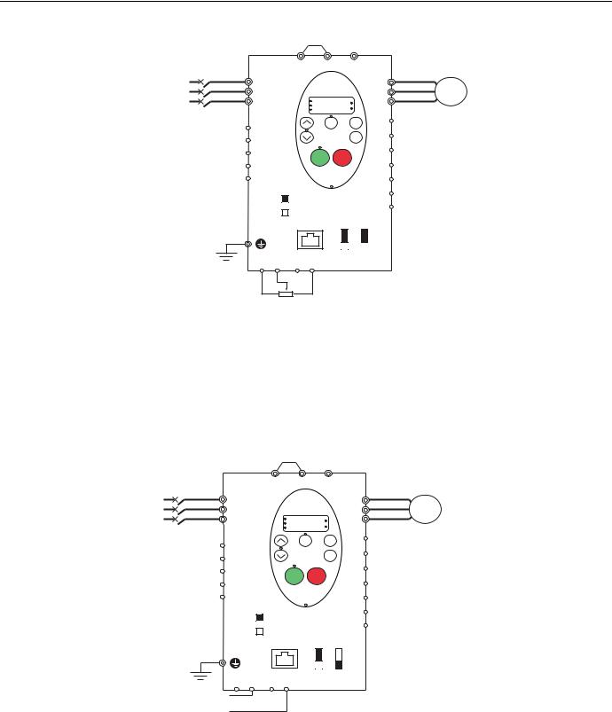
3-wire control
PO PA/+ PC/-
R/L1
S/L2
T/L3
RUN |
|
% |
|
|
|
PRG |
|
|
MON |
|
Hz |
|
Loc |
MODE |
|
Rem |
|
FLC |
|
|
|
|
|
FLB |
|
ENT |
|
|
FLA
RUN STOP
 RY
RY
 RC SW4
SOURCE
PLC
|
U/T1 |
|
|
V/T2 |
M |
|
W/T3 |
|
|
|
|
F |
|
|
R |
|
Start forward |
RES |
|
Stop |
FM
Start reverse
CC 
P24
PLC
SINK |
FM VIA |
V V
I I
PPVIA VIB CC
1.Wire the logic inputs as indicated in the above figure.
2.Set switch SW4 to source.
3.Program common parameters of ATV21 (see Quick Start page 37).
4.Program specific parameters for 3-wire control as indicated in the following table:
|
Parameter |
Page |
Setting |
Factory value |
CNOd (remote mode start/stop control) |
54 |
0 (control terminal logic inputs) |
0 |
|
|
|
|
|
|
F111 |
(F logic input function) |
80 |
2 (start forward - 3 wire control) |
2 |
|
|
|
|
|
F112 |
(R logic input function) |
80 |
49 (stop input - 3 wire control) |
6 |
|
|
|
|
|
F113 |
(RES logic input function) |
80 |
3 (start reverse - 3 wire control) |
10 |
|
|
|
|
|
3 wire control timing diagram: |
|
Output frequency |
|
Forward run |
|
|
0 |
Reverse run |
|
R - Stop |
ON |
OFF |
|
F - Forward start |
ON |
OFF |
|
RES - Reverse start |
ON |
OFF |
|
Line power |
ON |
OFF |
AAV75193 09/20009 |
25 |
Common control schemes
External speed control potentiometer
PO PA/+ PC/-
R/L1
S/L2
T/L3
RUN |
|
% |
|
|
|
PRG |
|
|
MON |
|
Hz |
|
Loc |
MODE |
|
Rem |
|
FLC |
|
|
|
|
ENT
FLB
U/T1 |
|
|
V/T2 |
M |
|
W/T3 |
||
|
||
F |
|
|
R |
|
FLA |
|
RES |
|
|
|
|
RUN |
STOP |
RY |
|
FM |
RC |
SW4 |
CC |
|
||
|
SOURCE |
P24 |
|
|
|
PLC |
PLC |
|
|
SINK |
FM VIA |
V V
I I
SW3
PP VIA VIB CC
2.2 to 10 kOhm - 1/4 Watt
1.Wire the analog input as indicated in the above figure.
2.Set switch SW3 to V (voltage).
3.Program common parameters of ATV21 (see Quick Start page 37).
4.Program specific parameters for external speed control potentiometer as indicated in the following table:
|
Parameter |
Page |
|
Setting |
Factory value |
FNOd (remote mode primary speed reference source) |
54 |
1 (VIA) |
1 |
||
|
|
|
|
|
|
F109 |
(VIA input function - analog or logic selection) |
80 |
0 |
(Analog input) |
0 |
|
|
|
|
|
|
F200 |
(auto/manual speed reference switching) |
83 |
0 |
(Enabled) |
0 |
|
|
|
|
|
|
4-20 mA speed control
PO PA/+ PC/-
R/L1
S/L2
T/L3
RUN |
|
% |
|
|
|
PRG |
|
|
MON |
|
Hz |
|
Loc |
MODE |
|
Rem |
|
FLC |
|
|
|
|
ENT
FLB
U/T1 |
|
|
V/T2 |
M |
|
W/T3 |
||
|
||
F |
|
|
R |
|
FLA |
|
RES |
|
|
|
|
RUN |
STOP |
RY |
|
FM |
RC |
SW4 |
CC |
|
||
|
SOURCE |
P24 |
|
|
|
PLC |
PLC |
|
|
SINK |
FM VIA |
V V
I I
SW3
PP VIA VIB CC
4-20 mA Current signal
1.Wire the analog input as indicated in the above figure.
2.Set switch SW3 to I (current).
3.Program common parameters of ATV21 (see Quick Start page 37).
4.Program specific parameters for 4-20 mA speed control as indicated in the following table:
|
Parameter |
Page |
|
Setting |
Factory value |
FNOd (remote mode primary speed reference source) |
54 |
1 (VIA) |
1 |
||
|
|
|
|
|
|
F109 |
(VIA input function - analog or logic selection) |
80 |
0 |
(Analog input) |
0 |
|
|
|
|
|
|
F200 |
(auto/manual speed reference switching) |
83 |
0 |
(Enabled) |
0 |
|
|
|
|
|
|
F201 |
(VIA speed reference level 1) |
81 |
20 % |
0 % |
|
|
|
|
|
|
|
|
|
|
|
|
|
26 |
AAV75193 09/20009 |
Common control schemes
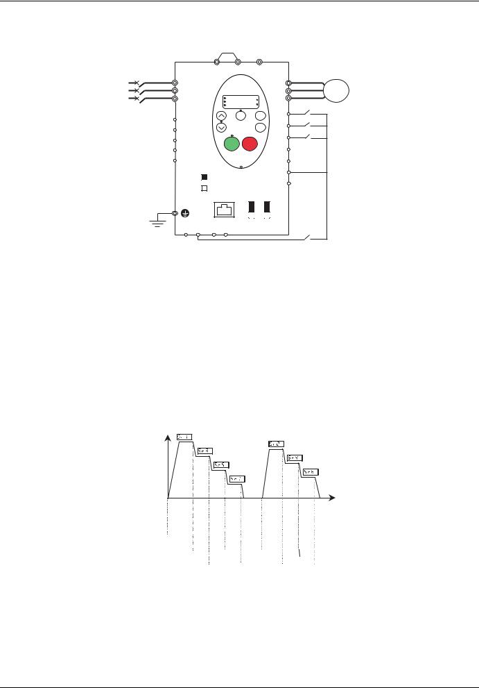
Preset speeds (up to seven)
|
PO |
PA/+ |
|
PC/- |
|
|
|
R/L1 |
|
|
|
|
|
U/T1 |
|
S/L2 |
|
|
|
|
|
V/T2 |
M |
T/L3 |
|
|
|
|
|
W/T3 |
|
|
|
|
|
|
|
||
|
|
RUN |
|
% |
|
|
|
|
|
|
|
|
|
|
|
|
|
PRG |
|
|
|
|
|
|
|
MON |
|
Hz |
|
|
|
|
|
|
Loc |
MODE |
F |
|
|
|
|
|
Rem |
|
|||
FLC |
|
|
|
|
|
||
|
|
|
|
|
|
|
|
FLB |
|
|
|
ENT |
|
R |
|
|
|
|
|
|
|
|
|
FLA |
|
|
|
|
|
RES |
|
|
|
|
|
|
|
|
|
|
|
RUN |
STOP |
|
|
|
|
RY |
|
|
|
|
|
FM |
|
RC |
SW4 |
|
|
|
|
CC |
|
|
|
|
|
|
|
||
|
SOURCE |
|
|
|
|
P24 |
|
|
|
|
|
|
|
|
|
PLC |
|
|
|
|
PLC |
|
|
|
SINK |
|
|
FM |
VIA |
|
|
|
|
|
V |
|
|
V |
|
|
|
|
I |
|
|
I |
|
PP VIA VIB CC |
|
|
|
|
|
||
1. Wire the logic and analog inputs as indicated in the above figure. |
|
|
|
|
|
||
2. Set switch SW4 to source. |
|
|
|
|
|
|
|
3. Program common parameters of ATV21 (see Quick Start page 37). |
|
|
|
||||
4. Program specific parameters for preset speed as indicated in the following table: |
|
||||||
|
Parameter |
Page |
|
Setting |
Factory value |
F109 |
(VIA input function - analog or logic selection) |
80 |
2 |
(logic input - source) |
0 |
|
|
|
|
|
|
F111 |
(F logic input function) |
80 |
2 |
(forward run command) |
2 |
|
|
|
|
|
|
F112 |
(R logic input function) |
80 |
6 |
(preset speed command input 1) |
6 |
|
|
|
|
|
|
F113 |
(RES logic input function) |
80 |
7 |
(preset speed command input 2) |
10 |
|
|
|
|
|
|
F118 |
(VIA logic input function) |
80 |
8 |
(preset speed command input 3) |
7 |
|
|
|
|
|
|
Example of 7-step preset speed operation:
Output |
|
frequency |
|
(Hz) |
|
0 |
Time (sec) |
|
|
|
|
|
|
|
|
|
|
|
|
ON |
F |
|
|
|
|
|
|
|
|
|
|
|
OFF |
|
|
|
|
|
|
|
|
|
|
|
||
|
|
|
|
|
|
|
|
|
|
|
|
ON |
R |
|
|
|
|
|
|
|
|
|
|
OFF |
|
|
|
|
|
|
|
|
|
|
|
|||
|
|
|
|
|
|
|
|
|
|
|
|
ON |
RES |
|
|
|
|
|
|
|
|
|
|
OFF |
|
|
|
|
|
|
|
|
|
|
|
|||
|
|
|
|
|
|
|
|
|
|
|
|
ON |
VIA |
|
|
|
|
|
|
|
|
|
|
|
OFF |
|
|
|
|
|
|
|
|
|
|
|
||
See page 90 for additionnal information.
AAV75193 09/20009 |
27 |
Common control schemes
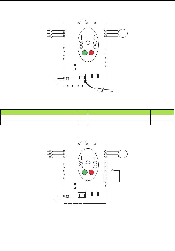
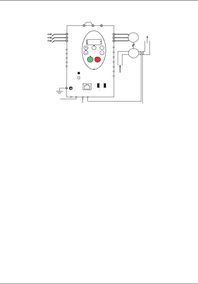
Serial communication
PO PA/+ PC/-
R/L1
S/L2
T/L3
RUN |
% |
|
|
PRG |
|
MON |
Hz |
U/T1 |
|
|
V/T2 |
M |
|
W/T3 |
||
|
 FLC
FLC
Loc
F
Rem
MODE
R 
FLB |
|
ENT |
|
|
|
RES |
|
|
|
|
|
FLA |
|
|
|
|
RUN |
STOP |
FM |
|
|
|
|
RY |
|
|
|
RC |
|
|
CC |
SW4 |
|
|
|
|
|
|
|
|
SOURCE |
|
P24 |
PLC |
|
PLC |
|
|
|
||
|
SINK |
FM VIA |
|
V V
I I
PPVIA VIB CC
1.For Modbus serial communication, plug the network cable into RJ45 connector on the main control board.
2.Program common parameters of ATV21 (see Quick Start page 37).
3.Program specific parameters for serial communication as indicated in the following table:
Parameter |
|
Page |
|
|
Setting |
Factory value |
|
CNOd (remote mode start/stop control) |
|
54 |
2 (serial communication) |
|
0 |
||
FNOd (remote mode primary speed reference source) |
54 |
4 (serial communication) |
|
1 |
|||
Forced local |
|
|
|
|
|
|
|
|
PO |
PA/+ |
PC/- |
|
|
|
|
R/L1 |
|
|
|
|
U/T1 |
|
|
S/L2 |
|
|
|
|
V/T2 |
M |
|
T/L3 |
|
|
|
|
W/T3 |
|
|
|
|
|
|
|
|
||
|
|
RUN |
% |
|
|
|
|
|
|
|
|
|
|
|
|
|
|
PRG |
|
|
|
|
|
|
|
MON |
Hz |
|
|
|
|
|
|
Loc |
MODE |
F |
|
|
|
|
|
Rem |
|
|
|||
FLC |
|
|
|
|
|
||
|
|
|
|
|
|
|
|
FLB |
|
|
ENT |
|
R |
|
|
|
|
|
|
|
|
|
|
FLA |
|
|
|
|
RES |
Forced |
|
|
|
|
|
FM |
|
||
RY |
|
RUN |
STOP |
|
|
||
RC |
SW4 |
|
|
|
CC |
local |
|
|
|
|
|
|
|
||
|
|
|
|
|
|
|
|
|
SOURCE |
|
|
|
P24 |
|
|
|
|
|
|
|
|
|
|
PLC |
|
|
|
PLC |
|
|
|
|
SINK |
|
FM |
VIA |
|
|
|
V V
I I
PPVIA VIB CC
1.Wire the logic input as indicated in the above figure.
2.Set switch SW4 to source.
3.Program common parameters of ATV21 (see Quick Start page 37).
4.Program specific parameter for forced local as indicated in the following table:
Parameter |
Page |
Setting |
Factory value |
F113 (RES logic input function) |
80 |
48 (forced local) |
10 |
|
|
|
|
28 |
AAV75193 09/20009 |
Common control schemes
PID control
|
|
PO |
PA/+ |
PC/- |
|
|
|
|
R/L1 |
|
|
|
|
|
|
U/T1 |
|
S/L2 |
|
|
|
|
|
|
V/T2 |
M |
T/L3 |
|
|
|
|
|
|
W/T3 |
|
|
|
|
|
|
|
|
||
|
|
|
RUN |
|
% |
|
|
|
|
|
|
|
|
|
|
|
|
|
|
|
PRG |
|
|
|
|
|
|
|
|
MON |
|
Hz |
|
|
|
|
|
|
|
Loc |
MODE |
F |
|
|
|
|
|
|
Rem |
|
|
||
FLC |
|
|
|
|
|
|
||
|
|
|
|
|
|
|
|
|
FLB |
|
|
|
|
ENT |
R |
|
P |
|
|
|
|
|
|
|
||
FLA |
|
|
RUN |
STOP |
|
RES |
|
Feedback |
RY |
|
|
|
|
|
FM |
|
transmitter |
RC |
SW4 |
|
|
|
CC |
|
|
|
|
|
|
|
|
|
|||
|
|
|
|
|
|
|
||
|
SOURCE |
|
|
|
P24 |
|
|
|
|
|
|
|
|
|
|
|
|
PLC |
|
|
|
|
PLC |
|
|
|
|
SINK |
|
FM |
VIA |
|
|
|
|
|
|
|
|
V |
|
V |
|
|
|
|
|
|
I |
|
I |
|
|
|
|
|
|
|
SW3 |
|
|
|
PP VIB |
CC VIA |
|
|
|
|
|
||
Setpoint 0 - 10 V |
|
|
|
|
|
|
|
|
Feedback mA or voltage signal
1.Wire analog inputs as indicated in the above figure.
2.Set switch SW4 to source.
3.If the feedback is a milliamp signal, set switch SW3 to the I (current) position. If the feedback is a voltage signal, set switch SW3 to the V (voltage) position.
4.Program common parameters of ATV21 (see Quick Start page 37).
5.Program specific parameters for PID control as indicated in the following table:
|
Parameter |
Page |
|
Setting |
Factory value |
|
FNOd (remote mode primary speed reference source) |
54 |
2 |
(VIB) |
1 |
||
|
|
|
|
|
|
|
F109 |
(VIA input function - analog or logic selection) |
80 |
0 |
(Analog input) |
0 |
|
|
|
|
|
|
|
|
F200 |
(auto/manual speed reference switching) |
83 |
0 |
(Enabled) |
0 |
|
|
|
|
|
|
|
|
F360 |
(PID control enable) |
86 |
1 |
(Enabled - feedback source is VIA) |
0 |
|
|
|
|
|
|
|
|
F359 |
(PID control waiting time) |
87 |
|
|
0 s |
|
|
|
|
|
|
|
|
F362 |
(PID proportionnal gain) |
86 |
|
|
0.30 % |
|
|
|
|
|
|
|
|
F363 |
(PID integral gain) |
86 |
|
|
0.20 |
|
|
|
|
|
|
|
|
F366 |
(PID derivative gain) |
87 |
In accordance with the application |
0.00 |
||
|
|
|
|
|||
F380 |
(PI regulator reversal direction correction) |
87 |
0 |
|||
|
|
|||||
|
|
|
|
|
|
|
F391 |
(Stop on LL hysteresis) |
87 |
|
|
0.2 Hz |
|
|
|
|
|
|
|
|
F392 |
(PI wake up threshold on PI error) |
87 |
|
|
0.0 Hz |
|
|
|
|
|
|
|
|
F393 |
(PI wake up threshold on PI feedback error) |
87 |
|
|
0.0 Hz |
|
|
|
|
|
|
|
|
AAV75193 09/20009 |
29 |

Drive Operation
Local and Remote Modes of Operation
Overview
The ATV21 drive has two modes of operation, local and remote.
In local mode, the ATV21 drive can be operated only from the graphic display terminal:
•Use the RUN and STOP keys for command control
•Use the UP and DOWN keys for speed control
In remote mode, the ATV21 drive is operated from a combination of the command and speed reference sources defined by programming parameters Remote Mode Primary Speed Reference Source FNOd and Remote Mode Start/Stop Control CNOd (see page 54).
Command Sources
The command source (CNOd) choices are:
•External signals to the control terminal logic inputs F, R, RES and VIA
•Serial communication control (Modbus®, Metasys® N2, Apogee® FLN, BACnet, or LonWorks®)
•Graphic display terminal RUN and STOP keys
Speed Reference Sources
The speed reference source (FNOd) choices are:
•External signals to the control terminal analog inputs VIA or VIB
•(4–20 mA, 0–10 Vdc),
•External signals to the control terminal logic inputs assigned to
•+/- Speed
•Serial communication control (Modbus®, Metasys® N2, Apogee® FLN, BACnet, or LonWorks®)
•graphic display terminal UP and DOWN keys
Changes to parameters FNOd and CNOd can only be made when the drive is stopped.
30 |
AAV75193 09/20009 |
Loading...