


 Loading...
Altivar Library
Function blocks
Software manual
V2.08, 04.2011
SoMachine
0198441113880, V2.08, 04.2011
www.schneider-electric.com
Important information |
Altivar Library |
|
|
Important information
This manual is part of the product.
Carefully read this manual and observe all instructions. Keep this manual for future reference.
Hand this manual and all other pertinent product documentation over to all users of the product.
Carefully read and observe all safety instructions and the chapter "Before you begin - safety information".
Some products are not available in all countries.
For information on the availability of products, please consult the catalog.
Subject to technical modifications without notice.
All details provided are technical data which do not constitute warranted qualities.
Most of the product designations are registered trademarks of their respective owners, even if this is not explicitly indicated.
0198441113880, V2.08, 04.2011
2 |
Function blocks |

Altivar Library |
Table of contents |
|
|
Table of contents
0198441113880, V2.08, 04.2011
Important information
Table of contents
About this manual
1Before you begin - safety information
1.1Qualification of personnel
1.2Intended use
1.3Hazard categories
1.4Basic information
1.5Standards and terminology
2Altivar Library Guide
2.1List of the function blocks
2.2Basic inputs and outputs
2.2.1Signal behavior of function blocks with the input Enable
2.2.2Signal behavior of function blocks with the input Execute
2.3Single axis
2.3.1Initialization
2.3.1.1MC_Power_ATV
2.3.2Operating mode Jog
2.3.2.1MC_Jog_ATV
2.3.3Operating mode Speed Control
2.3.3.1VelocityControlAnalogInput_ATV
2.3.3.2VelocityControlSelectAI_ATV
2.3.4Operating mode Profile Velocity
2.3.4.1MC_MoveVelocity_ATV
2.3.5Stopping
2.3.5.1MC_Stop_ATV
2.4Administrative
2.4.1Reading a parameter
2.4.1.1MC_ReadActualVelocity_ATV
2.4.1.2MC_ReadActualTorque_ATV
2.4.1.3MC_ReadStatus_ATV
2.4.1.4MC_ReadParameter_ATV
2.4.1.5GetSupplierVersion
2.4.2Writing a parameter
2.4.2.1MC_WriteParameter_ATV
2.4.2.2SetDriveRamp_ATV
2.4.2.3SetFrequencyRange_ATV
2.4.2.4ResetParameters_ATV
2
3
7
9
9
9
10
11
12
13
14
17
19
21
23
23
23
24
24
26
26
27
28
28
29
29
30
30
30
31
32
34
35
36
36
37
38
39
Function blocks |
3 |

Table of contents |
|
Altivar Library |
|||
|
|
|
|
|
|
|
|
|
2.4.2.5 |
StoreParameters_ATV |
40 |
|
|
2.4.3 |
Saving and restoring device configuration |
41 |
|
|
|
|
2.4.3.1 |
UploadDriveParameter_ATV |
41 |
|
|
|
2.4.3.2 |
DownloadDriveParameter_ATV |
42 |
|
|
2.4.4 |
Inputs and outputs |
43 |
|
|
|
|
2.4.4.1 |
ReadAnalogInput_ATV |
43 |
|
|
|
2.4.4.2 MC_ReadDigitalInput_ATV |
44 |
|
|
|
|
2.4.4.3 MC_ReadDigitalOutput_ATV |
46 |
|
|
|
|
2.4.4.4 MC_WriteDigitalOutput_ATV |
48 |
|
|
|
2.4.5 |
Error handling |
49 |
|
|
|
|
2.4.5.1 MC_ReadAxisError_ATV |
49 |
|
|
|
|
2.4.5.2 MC_Reset_ATV |
53 |
|
|
2.5 |
Device Function |
|
54 |
|
|
|
2.5.1 |
Startup |
|
54 |
|
|
|
2.5.1.1 |
Altivar_Startup |
54 |
|
|
2.5.2 |
Control |
|
63 |
|
|
|
2.5.2.1 |
Altivar31_Control |
63 |
|
|
|
2.5.2.2 |
Altivar71_Control |
72 |
|
|
|
2.5.2.3 |
Altivar32_Control |
81 |
3 |
Glossary |
|
|
93 |
|
|
3.1 |
Units and conversion tables |
93 |
||
|
|
3.1.1 |
Length |
|
93 |
|
|
3.1.2 |
Mass |
|
93 |
|
|
3.1.3 |
Force |
|
93 |
|
|
3.1.4 |
Power |
|
93 |
|
|
3.1.5 |
Rotation |
|
94 |
|
|
3.1.6 |
Torque |
|
94 |
|
|
3.1.7 |
Moment of inertia |
94 |
|
|
|
3.1.8 |
Temperature |
94 |
|
|
|
3.1.9 |
Conductor cross section |
94 |
|
|
3.2 |
Terms and Abbreviations |
95 |
||
4 |
Index |
|
|
|
97 |
0198441113880, V2.08, 04.2011
4 |
Function blocks |

Altivar Library
0198441113880, V2.08, 04.2011
Function blocks |
5 |

Altivar Library
0198441113880, V2.08, 04.2011
6 |
Function blocks |

Altivar Library |
About this manual |
|
|
About this manual
0198441113880, V2.08, 04.2011
This manual is an extract of the SoMachine Online Help. Fully read and understand all manuals of the SoMachine Online Help and of the products used.
Purpose of this document
This document describes the functions of the Altivar Library.
Software environment |
Devices |
Fieldbus |
|
|
|
SoMachine |
ATV31/ATV312 |
CANopen |
Device Descriptions of ver- |
ATV71/ATV32 |
|
sion 4.0.0.0 and higher are |
|
|
supported. |
|
|
|
|
|
Validity note
This document is valid for SoMachine as of Version 2.0.
Source manuals The latest versions of the manuals can be downloaded from the Internet at:
http://www.schneider-electric.com
Corrections and suggestions We always try to further optimize our manuals. We welcome your suggestions and corrections.
Please get in touch with us by e-mail: techcomm@schneider-electric.com.
Work steps If work steps must be performed consecutively, this sequence of steps is represented as follows:
■ Special prerequisites for the following work stepsStep 1
Specific response to this work step
If a response to a work step is indicated, this allows you to verify that the work step has been performed correctly.
Unless otherwise stated, the individual steps must be performed in the specified sequence.
SI units SI units are the original values. Converted units are shown in brackets behind the original value; they may be rounded.
Example:
Minimum conductor cross section: 1.5 mm2 (AWG 14) Glossary Explanations of special technical terms and abbreviations.
Index List of keywords with references to the corresponding page numbers.
Function blocks |
7 |
About this manual |
Altivar Library |
|
|
Disclaimer The information provided in this documentation contains general descriptions and/or technical characteristics of the performance of the products described here. This documentation is not intended as a substitute for and is not to be used for determining suitability or reliability of these products for specific user applications. It is the duty of any user or integrator to perform the appropriate and fully comprehensive risk analyses, evaluation and testing of the products with respect to the relevant specific application or use of the products. Neither Schneider Electric nor any of its affiliate or subsidiaries shall be responsible or liable for misuse of the information contained herein. If you have any suggestions for improvements or amendments or have found errors in this publication, please notify us.
No part of this document may be reproduced in any form or by any means, electronic or mechanical, including photocopying, without express written permission of Schneider Electric.
All pertinent state, regional, and local safety regulations must be observed when installing and using this product. For reasons of safety and to help ensure compliance with documented system data, only the manufacturer should perform repairs to components.
When devices are used for applications with technical safety requirements, the relevant instructions must be followed.
Failure to use Schneider Electric software or approved software with our hardware products may result in injury, harm, or improper operating results.
Failure to observe this information can result in injury or equipment damage.
0198441113880, V2.08, 04.2011
8 |
Function blocks |

Altivar Library |
1 Before you begin - safety information |
|
|
1 Before you begin - safety information
1
1.1Qualification of personnel
Only appropriately trained persons who are familiar with and understand the contents of this manual and all other pertinent product documentation are authorized to work on and with this product. In addition, these persons must have received safety training to recognize and avoid hazards involved. These persons must have sufficient technical training, knowledge and experience and be able to foresee and detect potential hazards that may be caused by using the product, by changing the settings and by the mechanical, electrical and electronic equipment of the entire system in which the product is used.
All persons working on and with the product must be fully familiar with all applicable standards, directives, and accident prevention regulations when performing such work.
1.2Intended use
This product is a library for industrial use with the appropriate controllers and drives.
The product may only be used in compliance with all applicable safety regulations and directives, the specified requirements and the technical data.
Prior to using the product, you must perform a risk assessment in view of the planned application. Based on the results, the appropriate safety measures must be implemented.
Since the product is used as a component in an entire system, you must ensure the safety of persons by means of the design of this entire system (for example, machine design).
Any use other than the use explicitly permitted is prohibited and can result in hazards.
Electrical equipment should be installed, operated, serviced, and maintained only by qualified personnel.
0198441113880, V2.08, 04.2011
Function blocks |
9 |
1 Before you begin - safety information |
Altivar Library |
|
|
1.3Hazard categories
Safety instructions to the user are highlighted by safety alert symbols in the manual. In addition, labels with symbols and/or instructions are attached to the product that alert you to potential hazards.
Depending on the seriousness of the hazard, the safety instructions are divided into 4 hazard categories.
DANGER
DANGER indicates an imminently hazardous situation, which, if not avoided, will result in death or serious injury.
WARNING
WARNING indicates a potentially hazardous situation, which, if not avoided, can result in death, serious injury, or equipment damage.
CAUTION
CAUTION indicates a potentially hazardous situation, which, if not avoided, can result in injury or equipment damage.
CAUTION
CAUTION used without the safety alert symbol, is used to address practices not related to personal injury (e.g. can result in equipment damage).
0198441113880, V2.08, 04.2011
10 |
Function blocks |
Altivar Library |
1 Before you begin - safety information |
|
|
1.4Basic information
WARNING
LOSS OF CONTROL
•The designer of any control scheme must consider the potential failure modes of control paths and, for certain critical functions, provide a means to achieve a safe state during and after a path failure. Examples of critical control functions are emergency stop, overtravel stop, power outage and restart.
•Separate or redundant control paths must be provided for critical functions.
•System control paths may include communication links. Consideration must be given to the implication of unanticipated transmission delays or failures of the link.
•Observe all accident prevention regulations and local safety guidelines. 1)
•Each implementation of the product must be individually and thoroughly tested for proper operation before being placed into service.
Failure to follow these instructions can result in death or serious injury.
1)For USA: Additional information, refer to NEMA ICS 1.1 (latest edition), “Safety Guidelines for the Application, Installation, and Maintenance of Solid State Control” and to NEMA ICS 7.1 (latest edition), “Safety Standards for Construction and Guide for Selection, Installation and Operation of Adjustable-Speed Drive Systems”.
WARNING
UNINTENDED BEHAVIOR DUE TO IMPROPER ERROR HANDLING
Improper error handling can change movements or signals or deactivate monitoring functions.
•Carefully program the error handling routines.
•Verify the effectiveness of error handling.
Failure to follow these instructions can result in death, serious injury or equipment damage.
WARNING
UNINTENDED BEHAVIOR DUE TO CHANGES TO THE LIBRARY
•Do not change or manipulate the library in any way whatsoever.
Failure to follow these instructions can result in death, serious injury or equipment damage.
0198441113880, V2.08, 04.2011
Function blocks |
11 |
1 Before you begin - safety information |
Altivar Library |
|
|
1.5Standards and terminology
Technical terms, terminology and the corresponding descriptions in this manual are intended to use the terms or definitions of the pertinent standards.
In the area of drive systems, this includes, but is not limited to, terms such as "safety function", "safe state", "fault", "fault reset", "failure", "error", "error message", "warning", "warning message", etc.
Among others, these standards include:
•IEC 61800 series: "Adjustable speed electrical power drive systems"
•IEC 61158 series: "Industrial communication networks - Fieldbus specifications"
•IEC 61784 series: "Industrial communication networks - Profiles"
•IEC 61508 series: "Functional safety of electrical/electronic/programmable electronic safety-related systems"
Also see the glossary at the end of this manual.
0198441113880, V2.08, 04.2011
12 |
Function blocks |

Altivar Library |
2 Altivar Library Guide |
|
|
2 Altivar Library Guide
2
0198441113880, V2.08, 04.2011
Library name Altivar Library (ATV)
Software environment |
Devices |
Fieldbus |
|
|
|
SoMachine |
ATV31/ATV312 |
CANopen |
Device Descriptions of ver- |
ATV71/ATV32 |
|
sion 4.0.0.0 and higher are |
|
|
supported. |
|
|
|
|
|
Naming conventions
Simple application
Categorization of the function blocks
The function blocks described here are used to control ATV drives in CANopen fieldbuses under the SoMachine software environment. The function blocks are compliant with the IEC 61131-3 standard.
•Function blocks with the prefix MC_ ("Motion Control") are compliant with the PLCopen specifications. They conform to a global standard for programming motion control applications.
•Function blocks without a prefix are vendor-specific (Schneider Electric); however, they comply with the general PLC open rules.
•The function blocks are used in the same way.
•The function blocks comply with the PLCopen state diagram.
•The function blocks feature a visualization that can be easily integrated into the application.
•Single axis: These function blocks are used for movements or functions of a single, independent axis.
•Administrative: These function blocks are used for configuration tasks (such as reading and writing of parameters, restoring a device configuration, etc.).
•Device Function: These function blocks support you in commissioning a drive at a controller. Before these function blocks can be used, you must correctly set the communication parameters baud rate and node address.
Preparing the drive Before you can access the drive via CANopen or CANmotion, you must make a number of settings. Among others, these settings include:
•Address and baud rate
•Profile (CHCF) = Separate
•Reference 1 (Fr1) = CAN
•Control channel (Cd1) = CAN
•Control channel switching (CSS) = Cd1
•Reference switching (rFC) = C214
Note the pertinent information in the product manual.
If you do not know the existing configuration, it may be useful to restore the factory settings. See "2.4.2.4 ResetParameters_ATV".
Function blocks |
13 |
2 Altivar Library Guide |
Altivar Library |
|
|
2.1List of the function blocks
Category Single axis
Category |
Subcategory |
Function block |
Type |
ATV31/ |
ATV71 |
ATV32 |
|
|
|
|
ATV312 |
|
|
|
|
|
|
|
|
|
Single axis |
|
|
|
|
|
|
|
|
|
|
|
|
|
|
Initialization |
"2.3.1.1 |
PLCopen |
X |
X |
X |
|
|
MC_Power_ATV" |
|
|
|
|
|
|
|
|
|
|
|
|
Operating mode |
"2.3.2.1 |
PLCopen |
X |
X |
X |
|
Jog |
MC_Jog_ATV" |
|
|
|
|
|
|
|
|
|
|
|
|
Operating mode |
"2.3.3.1 Velocity- |
Vendor-specific |
X |
X |
X |
|
Speed Control |
ControlAnalogIn- |
|
|
|
|
|
|
put_ATV" |
|
|
|
|
|
|
|
|
|
|
|
|
|
"2.3.3.2 Velocity- |
Vendor-specific |
X |
X |
X |
|
|
ControlSelec- |
|
|
|
|
|
|
tAI_ATV" |
|
|
|
|
|
|
|
|
|
|
|
|
Operating mode |
"2.3.4.1 MC_Move- |
PLCopen |
X |
X |
X |
|
Profile Velocity |
Velocity_ATV" |
|
|
|
|
|
|
|
|
|
|
|
|
Stopping |
"2.3.5.1 |
PLCopen |
X |
X |
X |
|
|
MC_Stop_ATV" |
|
|
|
|
|
|
|
|
|
|
|
0198441113880, V2.08, 04.2011
14 |
Function blocks |
Altivar Library |
|
|
2 Altivar Library Guide |
||||
|
|
|
|
|
|
|
|
|
Category Administrative |
|
|
|
|
|
|
|
|
|
|
|
|
|
|
Category |
|
Subcategory |
Function block |
Type |
ATV31/ |
ATV71 |
ATV32 |
|
|
|
|
|
ATV312 |
|
|
|
|
|
|
|
|
|
|
Administrative |
|
|
|
|
|
||
|
|
|
|
|
|
|
|
|
|
Reading a parame- |
"2.4.1.1 MC_Read- |
PLCopen |
X |
X |
X |
|
|
ter |
ActualVeloc- |
|
|
|
|
|
|
|
ity_ATV" |
|
|
|
|
|
|
|
|
|
|
|
|
|
|
|
"2.4.1.2 MC_Read- |
PLCopen |
X |
X |
X |
|
|
|
ActualTorque_ATV" |
|
|
|
|
|
|
|
|
|
|
|
|
|
|
|
"2.4.1.3 MC_Read- |
PLCopen |
X |
X |
X |
|
|
|
Status_ATV" |
|
|
|
|
|
|
|
|
|
|
|
|
|
|
|
"2.4.1.4 MC_Read- |
PLCopen |
X |
X |
X |
|
|
|
Parameter_ATV" |
|
|
|
|
|
|
|
|
|
|
|
|
|
|
|
"2.4.1.5 GetSup- |
Vendor-specific |
X |
X |
X |
|
|
|
plierVersion" |
|
|
|
|
|
|
|
|
|
|
|
|
|
|
Writing a parameter |
"2.4.2.1 MC_Write- |
PLCopen |
X |
X |
X |
|
|
|
Parameter_ATV" |
|
|
|
|
|
|
|
|
|
|
|
|
|
|
|
"2.4.2.2 SetDriveR- |
Vendor-specific |
X |
X |
X |
|
|
|
amp_ATV" |
|
|
|
|
|
|
|
|
|
|
|
|
|
|
|
"2.4.2.3 SetFre- |
Vendor-specific |
X |
X |
X |
|
|
|
quencyR- |
|
|
|
|
|
|
|
ange_ATV" |
|
|
|
|
|
|
|
|
|
|
|
|
|
|
|
"2.4.2.4 ResetPara- |
Vendor-specific |
X |
X |
X |
|
|
|
meters_ATV" |
|
|
|
|
|
|
|
|
|
|
|
|
|
|
|
"2.4.2.5 StorePara- |
Vendor-specific |
X |
X |
X |
|
|
|
meters_ATV" |
|
|
|
|
|
|
|
|
|
|
|
|
|
|
Saving and restor- |
"2.4.3.1 UploadDri- |
Vendor-specific |
X |
X |
X |
|
|
ing device configu- |
veParameter_ATV" |
|
|
|
|
|
|
ration |
|
|
|
|
|
|
|
"2.4.3.2 Download- |
Vendor-specific |
X |
X |
X |
|
|
|
|
|||||
|
|
|
DriveParame- |
|
|
|
|
|
|
|
ter_ATV" |
|
|
|
|
|
|
|
|
|
|
|
|
|
|
Inputs and outputs |
"2.4.4.1 ReadAna- |
Vendor-specific |
X |
X |
X |
|
|
|
logInput_ATV" |
|
|
|
|
|
|
|
|
|
|
|
|
|
|
|
"2.4.4.2 MC_Read- |
PLCopen |
X |
X |
X |
|
|
|
DigitalInput_ATV" |
|
|
|
|
|
|
|
|
|
|
|
|
|
|
|
"2.4.4.3 MC_Read- |
PLCopen |
X |
X |
X |
|
|
|
DigitalOutput_ATV" |
|
|
|
|
|
|
|
|
|
|
|
|
|
|
|
"2.4.4.4 MC_Write- |
PLCopen |
X |
X |
X |
|
|
|
DigitalOutput_ATV" |
|
|
|
|
|
|
|
|
|
|
|
|
|
|
Error handling |
"2.4.5.1 MC_Read- |
PLCopen |
X |
X |
X |
|
|
|
AxisError_ATV" |
|
|
|
|
|
|
|
|
|
|
|
|
|
|
|
"2.4.5.2 |
PLCopen |
X |
X |
X |
|
|
|
MC_Reset_ATV" |
|
|
|
|
|
|
|
|
|
|
|
|
0198441113880, V2.08, 04.2011
Function blocks |
15 |
2 Altivar Library Guide |
|
|
|
Altivar Library |
||
|
|
|
|
|
|
|
Category Device Function |
|
|
|
|
|
|
|
|
|
|
|
|
|
Category |
Subcategory |
Function block |
Type |
ATV31/ |
ATV71 |
ATV32 |
|
|
|
|
ATV312 |
|
|
|
|
|
|
|
|
|
Device Function |
|
|
|
|
|
|
|
|
|
|
|
|
|
|
Startup |
"2.5.1.1 Alti- |
Vendor-specific |
X |
X |
X |
|
|
var_Startup" |
|
|
|
|
|
|
|
|
|
|
|
|
Control |
"2.5.2.1 Alti- |
Vendor-specific |
X |
- |
- |
|
|
var31_Control" |
|
|
|
|
|
|
|
|
|
|
|
|
|
"2.5.2.2 Alti- |
Vendor-specific |
- |
X |
- |
|
|
var71_Control" |
|
|
|
|
|
|
|
|
|
|
|
|
|
"2.5.2.3 Alti- |
Vendor-specific |
- |
- |
X |
|
|
var32_Control" |
|
|
|
|
|
|
|
|
|
|
|
0198441113880, V2.08, 04.2011
16 |
Function blocks |
Altivar Library |
2 Altivar Library Guide |
|
|
2.2Basic inputs and outputs
Input/output |
Data type |
Description |
|
|
|
Axis |
Axis_Ref_ATV |
Name of the axis (instance) for which the function block is to |
|
|
be executed. The name must be declared in the PLC configu- |
|
|
ration. The name of the axis can be found to the left in the tree |
|
|
structure of your software. |
|
|
|
Input |
Input_Ref_ATV |
Input is a special data type for digital and analog inputs. The |
|
|
data type corresponds to the name of the axis (instance) to |
|
|
which the inputs belong (similar to Axis). |
|
|
In the case of function blocks specifically provided for reading |
|
|
analog and digital inputs, Input replaces the input Axis. |
Output |
Output_Ref_ATV |
Output is a special data type for digital and outputs. The data |
|
|
type corresponds to the name of the axis (instance) to which |
|
|
the outputs belong (similar to Axis). |
|
|
In the case of function blocks specifically provided for writing |
|
|
and reading analog and digital inputs, Output replaces the |
|
|
input Axis. |
Input |
Data type |
Description |
|
|
|
Enable |
BOOL |
Value range: TRUE, FALSE |
|
|
Initial value: FALSE |
|
|
The input Enable starts or terminates the execution of a func- |
|
|
tion block. (exception "2.3.1.1 MC_Power_ATV") |
|
|
FALSE: Execution of the function block is terminated. The out- |
|
|
puts Valid, Busy, CommandAborted and Error are set to |
|
|
FALSE. |
|
|
TRUE: The function block is executed repeatedly. |
|
|
|
Execute |
BOOL |
Value range: TRUE, FALSE |
|
|
Initial value: FALSE |
|
|
The input Execute starts the execution of a function block in |
|
|
the case of a rising edge (FALSE->TRUE). |
|
|
If a second rising edge is detected during the execution of the |
|
|
function block, the current execution is aborted and the func- |
|
|
tion block is executed again. |
|
|
Execution is terminated as soon as the output Busy is FALSE. |
|
|
FALSE and, at the same time, Busy = FALSE: |
|
|
Either Done, Error or CommandAborted are set to TRUE for |
|
|
one call. |
|
|
TRUE and, at the same time, Busy = FALSE: |
|
|
Either Done, Error or CommandAborted are set to TRUE |
|
|
and remain TRUE until Execute is set to FALSE. |
0198441113880, V2.08, 04.2011
Function blocks |
17 |
2 Altivar Library Guide |
Altivar Library |
|
|
|
|
|
|
|
Output |
Data type |
Description |
|
|
|
Done |
BOOL |
Value range: TRUE, FALSE |
|
|
Initial value: FALSE |
|
|
FALSE: Execution has not (yet) been terminated without an |
|
|
error. |
|
|
TRUE: Execution has been completed without an error. |
|
|
|
Valid |
BOOL |
Value range: TRUE, FALSE |
|
|
Initial value: FALSE |
|
|
FALSE: Execution has not (yet) been terminated without an |
|
|
error. The values at the outputs are not (yet) valid. |
|
|
TRUE: Execution has been completed without an error. The |
|
|
values at the outputs are valid and can be further processed. |
|
|
|
Busy |
BOOL |
Value range: TRUE, FALSE |
|
|
Initial value: FALSE |
|
|
FALSE: Execution of the function block has been terminated. |
|
|
TRUE: Function block is being executed. |
|
|
NOTE: In the operating mode Profile Velocity, the output |
|
|
remains TRUE even when the target velocity has been |
|
|
reached or Execute becomes FALSE. The output Busy is set |
|
|
to FALSE as soon as another function block such as MC_Stop |
|
|
is executed. |
|
|
|
CommandAborted |
BOOL |
Value range: TRUE, FALSE |
|
|
Initial value: FALSE |
|
|
FALSE: Execution has not (yet) been canceled without an |
|
|
error. |
|
|
TRUE: Execution has been aborted by another function block. |
|
|
|
Error |
BOOL |
Value range: TRUE, FALSE |
|
|
Initial value: FALSE |
|
|
FALSE: Execution of the function block is running, nor error |
|
|
has occurred up until now. |
|
|
TRUE: An error has occurred in the execution of the function |
|
|
block. |
|
|
|
0198441113880, V2.08, 04.2011
18 |
Function blocks |
Altivar Library |
2 Altivar Library Guide |
|
|
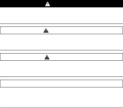
2.2.1Signal behavior of function blocks with the input Enable
Example 1 Single execution without error (execution requires more than one call).
Enable
Error
Valid
Busy
Example 2 Single execution with error (execution requires more than one call).
Enable
Error
Valid
Busy
0198441113880, V2.08, 04.2011
Example 3 Single execution without error (execution requires only one call).
Enable
Error
Valid
Busy
Example 4 Single execution with error (execution requires only one call).
Enable
Error
Valid
Busy
Function blocks |
19 |
2 Altivar Library Guide |
Altivar Library |
|
|
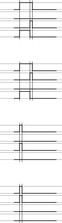
Example 5 Repeated execution without error (execution requires more than one call).
Enable
Error
Valid
Busy
Example 6 Repeated execution with error (execution requires more than one call).
Enable
Error
Valid
Busy
Example 7 Repeated execution without error (execution requires only one call).
Enable
Error
Valid
Busy
Example 8 Repeated execution with error (execution requires only one call).
Enable
Error
Valid
Busy
0198441113880, V2.08, 04.2011
20 |
Function blocks |
Altivar Library |
2 Altivar Library Guide |
|
|
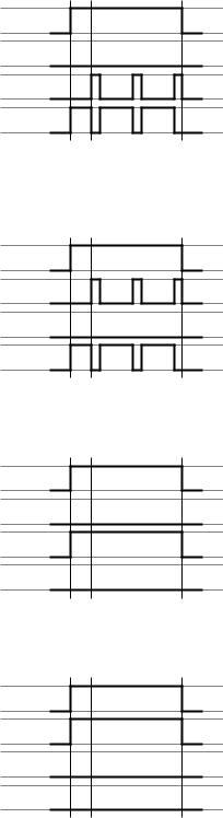
2.2.2Signal behavior of function blocks with the input Execute
Example 1 Execution terminated without error.
Execute
Error
Done
CommandAborted
Busy
Example 2 Execution terminated with error.
Execute
Error
Done
CommandAborted
Busy
Example 3 Abortion of the execution because another function block takes over control.
Execute
Error
Done
CommandAborted
Busy
0198441113880, V2.08, 04.2011
Function blocks |
21 |
2 Altivar Library Guide |
Altivar Library |
|
|
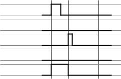
Example 4 Execution completed without error after Execute has been set to
FALSE during execution.
Execute
Error
Done
CommandAborted
Busy
0198441113880, V2.08, 04.2011
22 |
Function blocks |

Altivar Library |
2 Altivar Library Guide |
|
|
2.3Single axis
2.3.1Initialization
The initialization function block enables or disables the power stage. Other function blocks can only be used when the power stage is enabled.
2.3.1.1 MC_Power_ATV
Function description The function block enables or disables the power stage. TRUE at the input Enable enables the power stage. Once the power stage is enabled, the output Status is set. FALSE at the input Enable disables the power stage. Once the power stage is disabled, the output Status is reset. If errors occur during execution, the output Error is set.
Graphical representation
|
|
|
|
MC_Power_ATV |
|
|
|
|
Axis Axis_Ref_ATV |
BOOL Status |
|
|
|
|
|
||
|
|
|
|
||
|
|
|
Enable BOOL |
BOOL Error |
|
|
|
|
|
||
|
|
|
|
|
|
0198441113880, V2.08, 04.2011
Compatible devices ATV31/ATV312 and ATV71/ATV32
Inputs/outputs The table below shows the outputs.
Output |
Data type |
Description |
|
|
|
Status |
BOOL |
Value range: FALSE, TRUE |
|
|
Initial value: FALSE |
|
|
FALSE: Power stage is disabled. |
|
|
TRUE: Power stage is enabled. |
|
|
|
"2.2 Basic inputs and outputs"
Notes In the case of a Node Guarding error, the error memory must be reset by means of the function block "2.4.5.2 MC_Reset_ATV" before the power stage can be enabled again.
• An asynchronous motor has no torque when it is at a standstill. Enabling the power stage does not automatically generate torque.
• If the input Enable = TRUE, one of the following errors is signaled if the power supply is lost.
- 3120h (undervoltage)
- ATV71/ATV32: FF34h (PowerOnTimeout_ATV)
- If the 24V power supply is lost: 8100hh (NodeguardError_ATV) - The output Status is set to FALSE and the output Error to TRUE. Once the power supply is available again, the output
Status is set back to TRUE.
Function blocks |
23 |

2 Altivar Library Guide |
Altivar Library |
|
|
2.3.2Operating mode Jog
In the operating mode Jog, a movement is made from the actual motor position in the desired direction. The velocity can be set. As long as the signal for the direction is available, a continuous movement is made in the desired direction.
If movements in positive and negative directions are requested at the same time, there is no motor movement.
2.3.2.1 MC_Jog_ATV
Function description The function block starts the operating mode Jog. TRUE at the input Forward or the input Backward starts the jog movement. If both the inputs Forward and Backward are FALSE, the operating mode is terminated and the output Done is set. If both the inputs Forward and Backward are TRUE, the operating mode remains active, the jog movement is stopped and the output Busy remains set.
Graphical representation
|
|
|
|
MC_Jog_ATV |
|
|
|
|
Axis Axis_Ref_ATV |
BOOL Done |
|
|
|
|
|
||
|
|
|
|
||
|
|
|
Forward BOOL |
BOOL Busy |
|
|
|
|
|
||
|
|
|
Backward BOOL |
BOOL CommandAborted |
|
|
|
|
|
||
|
|
|
Velocity INT |
BOOL Error |
|
|
|
|
|
||
|
|
|
|
|
|
Compatible devices ATV31/ATV312 and ATV71/ATV32
0198441113880, V2.08, 04.2011
24 |
Function blocks |
Altivar Library |
|
|
|
2 Altivar Library Guide |
|
|
|||
|
Inputs/outputs The table below shows the inputs. |
|||
|
|
|
|
|
Input |
|
Data type |
|
Description |
|
|
|
|
|
Forward |
|
BOOL |
|
Value range: FALSE, TRUE |
|
|
|
|
Initial value: FALSE |
|
|
|
|
Forward = FALSE and Backward = FALSE: |
|
|
|
|
Movement is terminated. |
|
|
|
|
Forward = TRUE and Backward = FALSE: |
|
|
|
|
Movement in positive direction is started if Velocity >0. |
|
|
|
|
Movement in negative direction is started if Velocity <0. |
|
|
|
|
Forward = FALSE and Backward = TRUE: |
|
|
|
|
Movement in negative direction is started if Velocity >0. |
|
|
|
|
The movement is stopped if Velocity <0. |
|
|
|
|
Forward = TRUE and Backward = TRUE: |
|
|
|
|
The movement in the current direction continues. If the inputs |
|
|
|
|
Forward or Backward are set to FALSE, the movement is |
|
|
|
|
continued in the direction and at the velocity valid at that point |
|
|
|
|
in time. |
|
|
|
|
|
Backward |
|
BOOL |
|
Value range: FALSE, TRUE |
|
|
|
|
Initial value: FALSE |
|
|
|
|
Forward = FALSE and Backward = FALSE: |
|
|
|
|
Movement is terminated. |
|
|
|
|
Forward = TRUE and Backward = FALSE: |
|
|
|
|
Movement in positive direction is started if Velocity >0. |
|
|
|
|
Movement in negative direction is started if Velocity <0. |
|
|
|
|
Forward = FALSE and Backward = TRUE: |
|
|
|
|
Movement in negative direction is started if Velocity >0. |
|
|
|
|
The movement is stopped if Velocity <0. |
|
|
|
|
Forward = TRUE and Backward = TRUE: |
|
|
|
|
The movement in the current direction continues. If the inputs |
|
|
|
|
Forward or Backward are set to FALSE, the movement is |
|
|
|
|
continued in the direction and at the velocity valid at that point |
|
|
|
|
in time. |
|
|
|
|
|
Velocity |
|
INT |
|
Value range: -5000 ... +5000 |
|
|
|
|
Initial value: 0 |
|
|
|
|
Target velocity for the operating mode. Adjustable in incre- |
|
|
|
|
ments of 0.1 Hz. |
|
|
|
|
NOTE: |
|
|
|
|
The values for LowFrequency and HighFrequency are set |
|
|
|
|
in the function block SetFrequencyRange_ATV. |
|
|
|
|
If the value for the target velocity velocity is less than the |
|
|
|
|
value for LowFrequency, the movement is made with the |
|
|
|
|
velocity value for LowFrequency. No error is signaled. |
|
|
|
|
If the value for the target velocity velocity is greater than the |
|
|
|
|
value for HighFrequency, the movement is made with the |
|
|
|
|
velocity value for HighFrequency. No error is signaled. |
|
|
|
"2.2 Basic inputs and outputs" |
|
0198441113880, V2.08, 04.2011
Function blocks |
25 |
2 Altivar Library Guide |
Altivar Library |
|
|
2.3.3Operating mode Speed Control
In the operating mode Speed Control, you can set a reference velocity via an analog input.
2.3.3.1 VelocityControlAnalogInput_ATV
Function description The function block uses the reference values supplied by the analog input selected with the function block
"2.3.3.2 VelocityControlSelectAI_ATV".
Graphical representation
VelocityControlAnalogInput_ATV
Axis Axis_Ref_ATV |
BOOL InVelocity |
Execute BOOL |
BOOL Busy |
NegativeDir BOOL |
BOOL CommandAborted |
|
BOOL Error |
|
Compatible devices ATV31/ATV312 and ATV71/ATV32 |
||
|
Inputs/outputs The table below shows the inputs. |
||
|
|
|
|
Input |
|
Data type |
Description |
|
|
|
|
NegativeDir |
|
BOOL |
Value range: FALSE, TRUE |
|
|
|
Initial value: FALSE |
|
|
|
FALSE: Clockwise rotation. |
|
|
|
TRUE: Counter-clockwise rotation. |
|
|
|
|
|
|
The table below shows the outputs. |
|
|
|
|
|
Output |
Data type |
|
Description |
|
|
|
|
InVelocity |
BOOL |
|
Value range: FALSE, TRUE |
|
|
|
Initial value: FALSE |
|
|
|
FALSE: The velocity does not correspond to the reference |
|
|
|
value. |
|
|
|
FALSE: The velocity corresponds to the reference value. |
|
|
|
|
|
|
"2.2 Basic inputs and outputs" |
|
|
Notes See also "2.4.2.3 SetFrequencyRange_ATV" and |
||
|
|
"2.3.3.2 VelocityControlSelectAI_ATV". |
|
|
|
If voltage levels -10V ... 10V are used, the direction of movement |
|
|
|
(rotation) is inversed when the sign changes. If the voltage is 0 V, this |
|
|
|
may result in jumps in the direction of movement, in the minimum fre- |
|
|
|
quency and in jumps at standstill. |
|
|
|
NOTE for ATV31: If you have selected the analog current input |
|
|
|
(0 mA ... 20 mA), the following frequency levels are used: |
|
|
|
• The minimum frequency is used below 4 mA. |
|
|
|
• The medium frequency is used at 12 mA. |
|
|
|
• The maximum frequency is used at 20 mA. |
|
0198441113880, V2.08, 04.2011
26 |
Function blocks |

Altivar Library |
2 Altivar Library Guide |
|
|
2.3.3.2 VelocityControlSelectAI_ATV
Function description This function block is used to select the analog input for supplying the reference value. See also "2.3.3.1 VelocityControlAnalogInput_ATV".
Graphical representation
|
|
|
VelocityControlSelectAI_ATV |
|
|
|
|
|
Axis Axis_Ref_ATV |
BOOL Done |
|
|
|
|
|
||
|
|
|
|
||
|
|
|
Execute BOOL |
BOOL Busy |
|
|
|
|
|
||
|
|
|
InputNumber INT |
BOOL Error |
|
|
|
|
|
||
|
|
|
|
|
|
Compatible devices ATV31/ATV312 and ATV71/ATV32
Inputs/outputs The table below shows the inputs.
Input |
Data type |
|
Description |
|
|
|
|
InputNumber |
INT |
|
Value range: 1 ... 16 |
|
|
|
Initial value: 1 |
|
|
|
1: AI1 |
|
|
|
2: AI2 |
|
|
|
3: AI3 (ATV71 only with expansion card) |
|
|
|
4: AI4 (ATV71 only and only with expansion card) |
|
|
|
16: AIP (internal potentiometer, ATV31/312 only) |
|
|
|
|
|
|
"2.2 Basic inputs and outputs" |
|
|
Notes The function block can only be executed if the drive is in the operating |
||
|
|
state 3 Switch On Disabled (operating state of drive). To transition to |
|
|
|
this state, disable the power stage with the function block |
|
|
|
"2.3.1.1 MC_Power_ATV". |
|
0198441113880, V2.08, 04.2011
Function blocks |
27 |

2 Altivar Library Guide |
Altivar Library |
|
|
2.3.4Operating mode Profile Velocity
You can set a target velocity in the operating mode Profile Velocity. The movement is performed with this target velocity in the operating mode Profile Velocity. The movement continues until a new target velocity is set or until the operating mode is aborted.
Transitions between two target velocities are performed on the basis of a motion profile. The motion profile is determined by the profile generator in the drive on the basis of the actual velocity, the target velocity and the acceleration and deceleration ramps.
2.3.4.1 MC_MoveVelocity_ATV
Function description The function block starts the operating mode Profile Velocity with the velocity Velocity. When the target velocity is reached, InVelocity is set.
Graphical representation
MC_MoveVelocity_ATV
Axis Axis_Ref_ATV |
BOOL InVelocity |
Execute BOOL |
BOOL Busy |
Velocity INT |
BOOL CommandAborted |
|
BOOL Error |
Compatible devices ATV31/ATV312 and ATV71/ATV32
Inputs/outputs The table below shows the inputs.
Input |
Data type |
Description |
|
|
|
Velocity |
INT |
Value range: -5000 ... +5000 |
|
|
Initial value: 0 |
|
|
Target velocity in [0.1Hz] |
|
|
NOTE: |
|
|
The values for LowFrequency and HighFrequency are set |
|
|
in the function block SetFrequencyRange_ATV. |
|
|
If the value for the target velocity velocity is less than the |
|
|
value for LowFrequency, the movement is made with the |
|
|
velocity value for LowFrequency. No error is signaled. |
|
|
If the value for the target velocity velocity is greater than the |
|
|
value for HighFrequency, the movement is made with the |
|
|
velocity value for HighFrequency. No error is signaled. |
|
|
The table below shows the outputs. |
|
|
|
|
|
Output |
Data type |
|
Description |
|
|
|
|
InVelocity |
BOOL |
|
Value range: FALSE, TRUE |
|
|
|
Initial value: FALSE |
|
|
|
FALSE: Target velocity not yet reached. |
|
|
|
TRUE: Target velocity reached. |
|
|
|
|
|
|
"2.2 Basic inputs and outputs" |
|
|
Notes In the operating mode Profile Velocity, a position overtravel does not |
||
|
|
trigger an error. A position overtravel results in a loss of the zero point. |
|
0198441113880, V2.08, 04.2011
28 |
Function blocks |

Altivar Library |
2 Altivar Library Guide |
|
|
2.3.5Stopping
2.3.5.1 MC_Stop_ATV
Function description
Graphical representation
Compatible devices
Inputs/outputs
Notes
Each operating mode can be canceled by stopping. Stopping the operating mode does not generate an error.
The function block is used to stop the current movement. The operating mode is stopped by the function block.
|
|
|
|
MC_Stop_ATV |
|
|
|
|
Axis Axis_Ref_ATV |
BOOL Done |
|
|
|
|
|
||
|
|
|
|
||
|
|
|
Execute BOOL |
BOOL Busy |
|
|
|
|
|
||
|
|
|
|
BOOL Error |
|
|
|
|
|
|
|
|
|
|
|
|
|
ATV31/ATV312 and ATV71/ATV32 "2.2 Basic inputs and outputs"
The type of deceleration (deceleration ramp, coasting down without braking) is set via the parameter Stt. Note the pertinent information in the product manual.
•The deceleration ramp is set with the function block "2.4.2.2 SetDriveRamp_ATV".
•The function block can only be interrupted by disabling the power stage via the function block "2.3.1.1 MC_Power_ATV".
•As long as the input Execute is TRUE, no other function block with the exception of "2.3.1.1 MC_Power_ATV" can be started.
0198441113880, V2.08, 04.2011
Function blocks |
29 |

2 Altivar Library Guide |
Altivar Library |
|
|
2.4Administrative
2.4.1Reading a parameter
The following functions blocks allow you to read drive parameters such as the actual position or the actual velocity.
An additional function block provides read access to individual parameters of the device. See the product manual for a description of the parameters.
2.4.1.1 MC_ReadActualVelocity_ATV
Function description The function block is used to read the actual velocity of the motor.
Graphical representation
|
|
|
MC_ReadActualVelocity_ATV |
|
|
|
|
|
Axis Axis_Ref_ATV |
BOOL Valid |
|
|
|
|
|
||
|
|
|
|
||
|
|
|
Enable BOOL |
BOOL Busy |
|
|
|
|
|
||
|
|
|
|
BOOL Error |
|
|
|
|
|
|
|
|
|
|
|
INT Velocity |
|
|
|
|
|
|
|
|
|
|
|
|
|
|
Compatible devices |
ATV31/ATV312 and ATV71/ATV32 |
||
|
Inputs/outputs |
The table below shows the outputs. |
||
|
|
|
|
|
Output |
|
Data type |
|
Description |
|
|
|
|
|
Velocity |
|
INT |
|
Value range: -5000 ... +5000 |
|
|
|
|
Initial value: |
|
|
|
|
Actual velocity in min-1 |
|
|
|
"2.2 Basic inputs and outputs" |
|
|
|
Notes |
The function block uses Service Data Objects (SDO) to read the |
|
|
|
|
parameter from the device. Therefore, it is strongly recommended not |
|
|
|
|
to permanently set the input Enable to TRUE. This may cause over- |
|
|
|
|
load on the fieldbus. It is recommended to deactivate the function |
|
|
|
|
block when the output Busy is set to FALSE. |
|
|
|
|
The value is specified in min-1. Example: At a frequency of 3 Hz and 2 |
|
|
|
|
pairs of poles, this results in a velocity of 90 min-1. (3 Hz * 60 s / 2 |
|
|
|
|
pairs of poles = 90 min-1). Note that the reference value for the velocity |
|
|
|
|
("2.3.4.1 MC_MoveVelocity_ATV") is specified in increments of 0.1 Hz |
|
|
|
|
(3 Hz -> Velocity = 30). |
|
0198441113880, V2.08, 04.2011
30 |
Function blocks |
Loading...