


 Loading...
Ordering number: EN2305C
Thick Film Hybrid IC
STK4192II
AF Power Amplifier (Split Power Supply) (50W + 50W min, THD = 0.4%)
Features
•The STK4102II series (STK4192II) and STK4101V series (high-grade type) are pin-compatible in the output range of 6W to 50W and enable easy design.
•Small-sized package whose pin assignment is the same as that of the STK4101II series
•Built-in muting circuit to cut off various kinds of pop noise
•Greatly reduced heat sink due to substrate temperature 125°C guaranteed
•Excellent cost performance
Package Dimensions
unit: mm
4040
[STK4192II]
Specifications
Maximum Ratings at Ta = 25°C
Parameter |
Symbol |
Conditions |
Ratings |
Unit |
|
|
|
|
|
Maximum supply voltage |
VCC max |
|
±52.5 |
V |
Thermal resistance |
θj-c |
|
1.8 |
°C/W |
|
|
|
|
|
Junction temperature |
Tj |
|
150 |
°C |
|
|
|
|
|
Operating substrate temperature |
Tc |
|
125 |
°C |
|
|
|
|
|
Storage temperature |
Tstg |
|
−30 to +125 |
°C |
|
|
|
|
|
Available time for load short-circuit |
ts |
VCC = ±35V, RL = 8Ω, f = 50Hz, PO = 50W |
2 |
s |
Recommended Operating Conditions at Ta = 25°C |
|
|
||
Parameter |
Symbol |
Conditions |
Ratings |
Unit |
|
|
|
|
|
Recommended supply voltage |
VCC |
|
±35 |
V |
Load resistance |
RL |
|
8 |
Ω |
SANYO Electric Co., Ltd. Semiconductor Business Headquarters
TOKYO OFFICE Tokyo Bldg., 1-10, 1 Chome, Ueno, Taito-ku, TOKYO, 110 JAPAN
70997HA (ID) / D2593YK / 0078TA / 7167AT, TS No. 2305—1/8
STK4192II
Operating Characteristics |
at Ta = 25°C, VCC = ±35V, RL = 8Ω, Rg = 600Ω, VG = 40dB, |
|
|
||||||
|
|
RL : non-inductive load |
|
|
|
|
|
||
|
|
|
|
|
|
|
|
|
|
Parameter |
|
Symbol |
|
Conditions |
min |
typ |
|
max |
Unit |
|
|
|
|
|
|
|
|
|
|
Quiescent current |
|
ICCO |
VCC = ±42V |
20 |
40 |
|
100 |
mA |
|
|
|
PO (1) |
THD = 0.4%, |
50 |
|
|
|
W |
|
Output power |
|
f = 20Hz to 20kHz |
|
|
|
||||
|
|
|
|
|
|
|
|
|
|
|
PO (2) |
VCC = ±31V, THD = 1.0%, |
55 |
|
|
|
W |
||
|
|
|
|
|
|||||
|
|
RL = 4Ω, f = 1kHz |
|
|
|
||||
|
|
|
|
|
|
|
|
||
Total harmonic distortion |
|
THD |
PO = 1.0W, f = 1kHz |
|
|
|
0.3 |
% |
|
Frequency response |
|
f , f |
P |
= 1.0W, +0 dB |
|
20 to 50k |
|
|
Hz |
|
|
L H |
O |
–3 |
|
|
|
|
|
Input impedance |
|
ri |
PO = 1.0W, f = 1kHz |
|
55 |
|
|
kΩ |
|
Output noise voltage |
|
VNO |
VCC = ±42V, Rg = 10kΩ |
|
|
|
1.2 |
mVrms |
|
Neutral voltage |
|
VN |
VCC = ±42V |
–70 |
0 |
|
+70 |
mV |
|
Muting voltage |
|
VM |
|
|
–2 |
–5 |
|
–10 |
V |
Notes. |
For power supply at the time of test, use a constant-voltage power supply |
|
unless otherwise specified. |
|
For measurement of the available time for load short-circuit and output |
|
noise voltage, use the specified transformer power supply shown right. |
|
The output noise voltage is represented by the peak value on rms scale |
|
(VTVM) of average value indicating type. For AC power supply, use an |
|
AC stabilized power supply (50Hz) to eliminate the effect of flicker noise |
|
in AC primary line. |
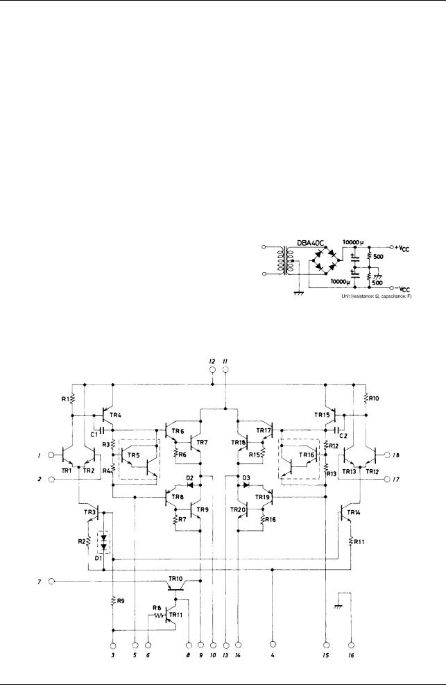
Equivalent Circuit
Specified Transformer Power Supply
(Equivalent to MG-200)
No. 2305—2/8

STK4192II
Sample Application Circuit : 50W min 2-channel AF power amplifier
Sample Printed Circuit Pattern for Application Circuit (Cu-foiled side)
No. 2305—3/8
Loading...