


ESPAÑOL ENGLISH
37I0521A_EnSp.indb 1 |
|
|
3/24/09 4:19:46 PM |
|
|
||
|
|
ENGLISH
ONE-YEAR LIMITED PARTS AND LABOR WARRANTY
THIS LIMITED PARTS AND LABOR WARRANTY IS VALID ONLY ON SANYO TELEVISIONS PUR-
CHASED AND USED IN THE UNITED STATES OF AMERICA, CANADA, AND PUERTO RICO,
EXCLUDING ALL OTHER U.S. TERRITORIES AND PROTECTORATES. THIS LIMITED WARRANTY
APPLIES ONLY TO THE ORIGINAL RETAIL PURCHASER, AND DOES NOT APPLY TO PRODUCTS
USED FOR INDUSTRIAL OR COMMERCIAL PURPOSES.
WARRANTY APPLICATION
FOR ONE YEAR from the date of original retail purchase Sanyo Manufacturing Corporation (SMC) warrants this TV to be free from manufacturing defects in materials and workmanship under normal use and conditions for parts and labor.
For the FIRST 90 DAYS from the date of original retail purchase, Sanyo Manufacturing Corporation will replace any defective TV via exchange at the retailer. To ensure proper warranty application, keep the original-dated-sales receipt for evidence of purchase. Return the defective TV to the retailer along with the receipt and the included accessories, such as the remote control. The defective TV will be exchanged for the same model, or a replacement model of equal value, if necessary. Replacement model will be contingent on availability and at the sole discretion of Sanyo Manufacturing Corporation.
THE FOREGOING WARRANTY IS EXCLUSIVE AND IN LIEU OF ALL OTHER WARRANTIES OF MER-
CHANTABILITY OR FITNESS FOR A PARTICULAR PURPOSE.
OBLIGATIONS
For one year from the date of purchase, Sanyo Manufacturing Corporation warrants this product to be free from defects in material and workmanship under normal use and conditions. During the first 90 days under this warranty for any manufacturing defect or malfunction Sanyo Manufacturing Corporation will provide a new TV via exchange at the retailer.
HOW TO MAKE A CLAIM UNDER THIS WARRANTY
Please call 1-800-877-5032. Please be prepared to give us the television’s model number and serial number when you call. The model number and serial number are printed on a label attached to
the back of the unit.
For customer assistance, call toll free 1-800-877-5032. 7:30 AM – 12:00 AM Midnight CT Mon-Sun
This warranty expresses specific contractual rights; retail purchasers may have additional statutory rights which vary from state to state.
(EFFECTIVE: March 1, 2007)
Your Sanyo HDTV is registered at the time of purchase, please keep sales receipt for future reference.
For your protection in the event of theft or loss of this product, please fill in the information requested below and KEEP IN A SAFE PLACE FOR YOUR OWN PERSONAL RECORDS.
Model No. _________________________ |
Date of Purchase ____________________ |
Serial No ._________________________ |
Purchase Price ______________________ |
|
Where Purchased ____________________ |
Sanyo Manufacturing Corp.
3333 Sanyo Road, Forrest City, AR 72335
2
37I0521A_EnSp.indb 2 |
3/24/09 4:19:50 PM |
TRADEMARKS
Manufactured under license from Dolby Laboratories. “Dolby” is a trademark of Dolby Laboratories.
HDMI, the HDMI Logo and High-Definition Multimedia Interface are trademarks or registered trademarks of HDMI Licensing LLC.
“As an Energy Star® Partner, Sanyo Manufacturing Corporation has determined that this product meets the EnergyStar® guidelines for energy efficiency.”
ENERGY STAR
ENGLISH
This symbol on the nameplate means the product is Listed by Unerwriter’s Laboratories Inc.
It is designed and manufactured to meet rigid U.L. safety standards against risk of fire,
casualty and electrical hazards.
SANYO recommends keeping the TV set at its factory settings or moving Energy Saver settings from “Level 1” to “Level 2” or “Level 3” to further reduce power requirements and increase energy savings. Doing so contributes to the sustainability of our resources and environment.
For more information visit www.energystar.gov
3
37I0521A_En.indd 3 |
3/27/09 9:59:16 AM |
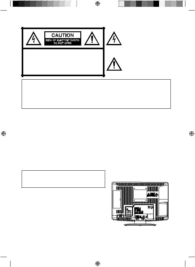
CAUTION: TO REDUCE THE RISK OF ELECTRIC SHOCK, DO NOT REMOVE COVER (OR BACK). NO USER-SERVICEABLE PARTS INSIDE. REFER SERVICING TO QUALIFIED SERVICE PERSONNEL.
The lightning flash with arrowhead symbol, within an equilateral triangle is intended to alert the user to the presence of uninsulated dangerous voltage within the product's enclosure that may be of sufficient magnitude to constitute a risk of electric shock.
The exclamation point within an equilateral triangle is intended to alert the user to the presence of important operating and maintenance (servicing) instructions in the literature accompanying the appliance.
WARNING: TO PREVENT FIRE OR SHOCK HAZARD, DO NOT EXPOSE THIS APPLIANCE TO RAIN OR MOISTURE.
TO PREVENT THE SPREAD OF FIRE, KEEP CANDLES OR OPEN FLAMES AWAY FROM THIS PRODUCT AT TIMES.
CAUTION: TO PREVENT ELECTRIC SHOCK DO NOT USE THIS POLARIZED PLUG WITH AN EXTENSION CORD, RECEPTACLE OR OTHER OUTLET UNLESS THE BLADES CAN BE FULLY INSERTED TO PREVENT BLADE EXPOSURE.
WARNING: This equipment has been tested and found to comply with the limits for a Class B digital device, pursuant to Part 15 of the FCC Rules. These limits are designed to provide reasonable protection against harmful interference in a residential installation. This equipment generates, uses and can radiate radio frequency energy and, if not installed and used in accordance with the instructions, may cause harmful interference to radio communications.
However, there is no guarantee that interference will not occur in a particular installation. If this equipment does cause harmful interference to radio or television reception, which can be determined by turning the equipment off and on, the user is encouraged to try to correct the interference by one or more of the following measures:
- Reorient or relocate the receiving antenna.
- Increase the separation between the equipment and receiver.
- Connect the equipment into an outlet on a circuit different from that to which the receiver is connected. - Consult the dealer or an experienced radio/TV technician for help.
CAUTION: Changes or modifications not expressly approved by the party responsible for compliance with the FCC Rules could void the user's authority to operate this equipment.
The lamp(s) within this product contain mercury. Disposal should be in compliance with local, state or federal laws.
Location of the required Marking
The rating sheet and the safety caution are on the rear of the unit.
Record the model number and serial number.
Model number _______________ Serial number _______________
4
37I0521A_EnSp.indb 4 |
3/24/09 4:19:51 PM |

ENGLISH
15)Apparatus should not be exposed to dripping or splashing, and objects filled with liquids, such as vases, should not be placed on the apparatus.
16)An outside antenna system should not be located in the vicinity of overhead power lines or other electric light or power circuits, or where it can fall into such power lines or circuits. When installing an outside antenna system, extreme care should be taken to keep from touching such power lines or circuits, as contact with them might be fatal.
17)Do not overload wall outlets and extension cords, as this can result in a risk of fire or electric shock.
18)Do not push objects through any openings in this unit, as they may touch dangerous voltage points or short out parts that could result in fire or electric shock. Never spill or spray any type of liquid into the unit.
19) If an outside antenna or cable system |
EXAMPLE OF ANTENNA GROUNDING AS PER THE NATIONAL ELECTRICAL CODE |
|||||||
is connected to the unit, be sure the |
|
|
|
|
|
|
|
|
antenna or cable system is grounded |
|
|
|
|
|
|
|
ANTENNA LEAD IN WIRE |
to provide some protection against |
GROUND |
|
|
|
|
|
||
voltage surges and built-up static |
|
|
|
|
ANTENNA |
|||
CLAMP |
|
|
|
|
||||
charges, Section 810 of the National |
|
|
|
|
|
|
|
DISCHARGE UNIT |
Electrical Code, ANSI/NFPA 70, provides |
|
|
|
|
|
|
|
(NEC SECTION 810-20) |
ELECTRIC SERVICE |
|
|
|
|
|
|||
information with respect to proper |
|
|
|
|
GROUNDING CONDUCTORS |
|||
EQUIPMENT |
|
|
|
|
(NEC SECTION 810-21) |
|||
grounding of the mast and supporting |
|
|
|
|
|
GROUND CLAMPS |
||
structure, grounding of the lead-in |
NEC-NATIONAL ELECTRICAL CODE |
|
|
|
POWER SERVICE GROUNDING |
|||
|
|
|
||||||
wire to an antenna discharge unit, size |
S2898A |
|
|
ELECTRODE SYSTEM |
||||
|
|
|
|
|
(NEC ART 250, PART H) |
|||
of grounding conductors, location of |
|
|
|
|
|
|
|
|
antenna discharge unit, connection to |
|
|
|
|
|
|
|
|
grounding electrodes, and requirements for the grounding electrode. |
|
|
|
|
|
|||
|
|
|
|
5 |
||||
37I0521A_EnSp.indb 5 |
|
|
|
|
|
|
|
3/24/09 4:19:53 PM |
IMPORTANT SAFETY INSTRUCTIONS
20)When replacement parts are required, be sure the service technician uses replacement parts specified by the manufacturer or those that have the same characteristics as the original part. Unauthorized substitutions may result in fire, electric shock or other hazards.
21)Upon completion of any service or repairs to this unit, ask the service technician to perform safety checks to determine that the unit is in proper operating condition.
22)When you connect the product to other equipment, turn off the power and unplug all of the equipment from the wall outlet. Failure to do so may cause an electric shock and serious personal injury. Read the owner's manual of the other equipment carefully and follow the instructions when making any connections.
23)Sudden high volume sound may cause hearing or speaker damage. When you use headphones, (if the unit is equipped with a headphone jack) keep the volume at a moderate level. If you use headphones continuously with high volume sound, it may cause hearing damage.
24)Do not allow the product to output distorted sound for an extended period of time. It may cause speaker overheating and fire.
25)This reminder is provided to call the cable TV system installer’s attention to Article 820-40 of the NEC that provides guidelines for proper grounding and, in particular, specifies that the cable ground shall be connected to the grounding system of the building, as close to the point of cable entry as practical.
26)The socket-outlet must be installed near the unit and easily accessible.
CHILD SAFETY:
It Makes A Difference How and Where You Use Your Flat Panel Display
Congratulations on your purchase! As you enjoy your new product, please keep these safety tips in mind:
THE ISSUE
The home theater entertainment experience is a growing trend and larger flat panel displays are popular purchases. However, flat panel displays are not always supported on the proper stands or installed according to the manufacturer’s recommendations.
Flat panel displays that are inappropriately situated on dressers, bookcases, shelves, desks, speakers, chests or carts may fall over and cause injury.
THIS MANUFACTURER CARES!
The consumer electronics industry is committed to making home entertainment enjoyable and safe.
TUNE INTO SAFETY
One size does NOT fit all. Follow the manufacturer’s recommendations for the safe installation and use of your flat panel display.
Carefully read and understand all enclosed instructions for proper use of this product.
Don’t allow children to climb on or play with furniture and television sets.
Don’t place flat panel displays on furniture that can easily be used as steps, such as a chest of drawers. Remember that children can become excited while watching a program, especially on a “larger than life” flat panel display. Care should be taken to place or install the display where it cannot be pushed, pulled over, or knocked down.
Care should be taken to route all cords and cables connected to the flat panel display so that they cannot be pulled or grabbed by curious children.
WALL MOUNTING: IF YOU DECIDE TO WALL MOUNT YOUR FLAT PANEL DISPLAY, ALWAYS:
Use a mount that has been recommended by the display manufacturer and/or listed by an independent laboratory (such as UL, CSA, ETL).
Follow all instructions supplied by the display and wall mount manufacturers.
If you have any doubts about your ability to safely install your flat panel display, contact your retailer about professional installation.
Make sure that the wall where you are mounting the display is appropriate to support the weight of the unit/ product and wall mount. If you are unsure, contact a professional installer.
A minimum of two people are required for installation. Flat panel displays can be heavy.
6
37I0521A_EnSp.indb 6 |
3/24/09 4:19:54 PM |
IMPORTANT SAFETY INSTRUCTIONS
CONDENSATION
Moisture will form in the operating section of the unit if the unit is brought from cool surroundings into a warm room or if the temperature of the room rises suddenly. When this happens, unit's performance will be impaired. To prevent this, let the unit stand in its new surroundings for about an hour before switching it on, or make sure that the room temperature rises gradually.
Condensation may also form during the summer if the unit is exposed to the breeze from an air conditioner. In such cases, change the location of the unit.
HOW TO HANDLE THE LCD PANEL
• Do not press hard or jolt the LCD panel. It may cause the LCD panel glass to break and injury may occur.
• If the LCD panel is broken, make absolutely sure that you do not touch the liquid in the panel. This may cause skin inflammation.
If the liquid gets in your mouth, immediately gargle and consult with your doctor. Also, if the liquid gets in your eyes or touches your skin, consult with your doctor after rinsing for at least 15 minutes or longer in clean water.
Possible Adverse Effects on LCD Panel: If a fixed (non-moving) pattern remains on the LCD Panel for long periods of time, the image can become permanently engrained in the LCD Panel and cause subtle but permanent ghost images. This type of damage is NOT COVERED BY YOUR WARRANTY. Never leave your LCD Panel on for long periods of time while it is displaying the following formats or images:
• Fixed Images, such as stock tickers, video game patterns, TV station logos, and websites.
• Special Formats that do not use the entire screen. For example, viewing letterbox style (16:9) media on a normal (4:3) display (black bars at top and bottom of screen); or viewing normal style (4:3) media on a widescreen (16:9) display (black bars on left and right sides of screen).
The following symptoms are not signs of malfunction but technical limitation. Therefore we disclaim any responsibility for these symptoms.
• LCD Panels are manufactured using an extremely high level of precision technology, however sometimes parts of the screen may be missing picture elements or have luminous spots.
This is not a sign of a malfunction.
• Do not install the LCD Panel near electronic equipment that is susceptible to electromagnetic waves. Some equipment placed too near this unit may cause interference.
• Effect on infrared devices – There may be interference while using infrared devices such as infrared cordless headphones.
SAFETY PRECAUTIONS
ENGLISH
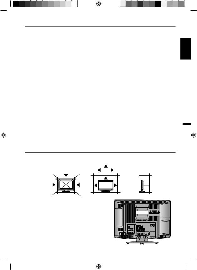
The unit emits heat when in operation. Do not place any covers or blankets on the unit, this may cause overheating.
Do not block ventilation holes, or set up near radiators. Do not place in direct sunshine. When placing on a shelf leave 10 cm (4 inches) free space around the entire unit.
10cm
10cm
Notes when mounting the LCD TV on a wall
• If the unit is to be mounted on the wall, contact the retailer where you purchased the LCD TV for advice, and have the equipment professionally installed. Incomplete or improper installation may cause injury to you, and/or damage to the LCD TV.
• Bracket holes: To attach a wall mounting bracket (not supplied) attach where indicated in the drawing right.
• This manufacturer recommends professional installation.
• Utilize an appropriate bracket and fasteners, sufficient to accommodate the size and weight of the unit.
• Assure the wall to which the unit is to be mounted will safely support the size and weight of the unit, using the bracket and fasteners you have selected.
• Keep cords and cables connected to this flat panel display out of reach of children.
• To hang the television on a wall, remove these screws and then remove a stand. Before performing work spread cushioning over the base area to lay the TV on.
Bracket holes
Screws
7
37I0521A_EnSp.indb 7 |
3/24/09 4:19:54 PM |
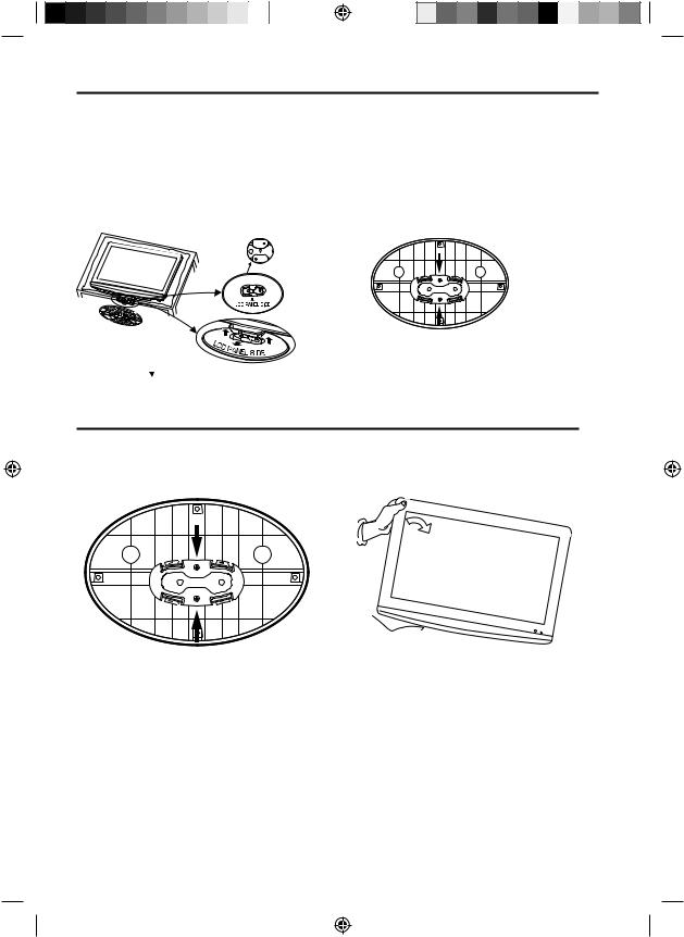
How to attach the stand
NOTE:
•Unplug the AC cord from the AC INPUT terminal.
•Before beginning this process, assure that TV is laid on a clean, safe, and cushioned space to avoid any damage to the unit.
•Do not touch or press the TV-screen, glass might break under pressure.
Place the TV on its back onto a table.
Align the stand’s bottom-plate (supplied) as seen here.
It will fit in only one direction.
Press it in direction of arrow until you hear ‘click’.
Finally secure the bottom-plate with 2 screws
(supplied).
Please assure “ ” mark on the stand is facing the LCD panel side.
How to remove the stand
When you transport this product, remove the stand and pack flat against the back of the unit in the carton. To remove the stand, remove the two (2) screws from the bottom (see A), and hold the stand on a flat surface lifting one side of the unit until stand disconnects (see B).
A 
 B
B
For wall mounting, the base must be removed. To disconnect the base/stand remove the two (2) screws from the back (see page 7).
8
37I0521A_EnSp.indb 8 |
3/24/09 4:19:56 PM |
|
|
|
|
|
|
|
|
|
|
|
|
|
|
|
|
|
|
|
|
|
|
|
|
|
|
|
|
|
|
|
|
|
|
|
|
|
|
|
|
|
|
|
|
|
|
Features |
|
|
|
|
|||||
|
|
• |
Integrated Digital Tuner - You can view digital broadcasts without using a Digital TV Set-Top Box. |
|
|
|
|
|
|||||||||||||||||||
|
|
• |
Closed Caption Decoder With Full Text Mode - Displays text captions or full screen text on the screen for |
|
|
|
|
||||||||||||||||||||
|
|
|
hearing impaired viewers. |
|
|
|
|
||||||||||||||||||||
|
|
• |
Picture Adjustments Using The Remote Control - The On-Screen display allows precise remote control |
|
ENGLISH |
||||||||||||||||||||||
|
|
|
adjustment of BRIGHTNESS, CONTRAST, COLOR, TINT and SHARPNESS. |
|
|||||||||||||||||||||||
|
|
• Programmable TV Sleep Timer - Operable from the remote control, the LCD TV can be programmed for up |
|
|
|
|
|||||||||||||||||||||
|
|
• |
to 120 minutes to turn off automatically. |
|
|
|
|
||||||||||||||||||||
|
|
V-Chip - The V-Chip function can read the rating of a broadcast program or movie content if the program is |
|
|
|
|
|||||||||||||||||||||
|
|
• |
encoded with this information. V-chip will allow you to set a restriction level. |
|
|
|
|
||||||||||||||||||||
|
|
Digital Audio Jack (Coaxial) - When a component with a built-in Dolby Digital decoder is connected, Dolby |
|
|
|
|
|||||||||||||||||||||
|
|
• |
Digital sound can produce the effect of being in a movie theater or a concert hall. |
|
|
|
|
||||||||||||||||||||
|
|
S-Video/Component Video Jacks - A VCR, DVD player, satellite receiver or other audio/video component |
|
|
|
|
|||||||||||||||||||||
|
|
|
can be connected to this unit. |
|
|
|
|
||||||||||||||||||||
|
|
• Video Input Jacks - This unit is equipped with 3 types of video input jacks. The component video in jacks and |
|
|
|
|
|||||||||||||||||||||
|
|
• |
S-video in jack enable you to watch the DVD player or the video devices with high quality picture. |
|
|
|
|
||||||||||||||||||||
|
|
On-Screen 3 Language Display - You can select one of 3 languages, English, French or Spanish for on- |
|
|
|
|
|||||||||||||||||||||
|
|
|
screen programming. |
|
|
|
|
||||||||||||||||||||
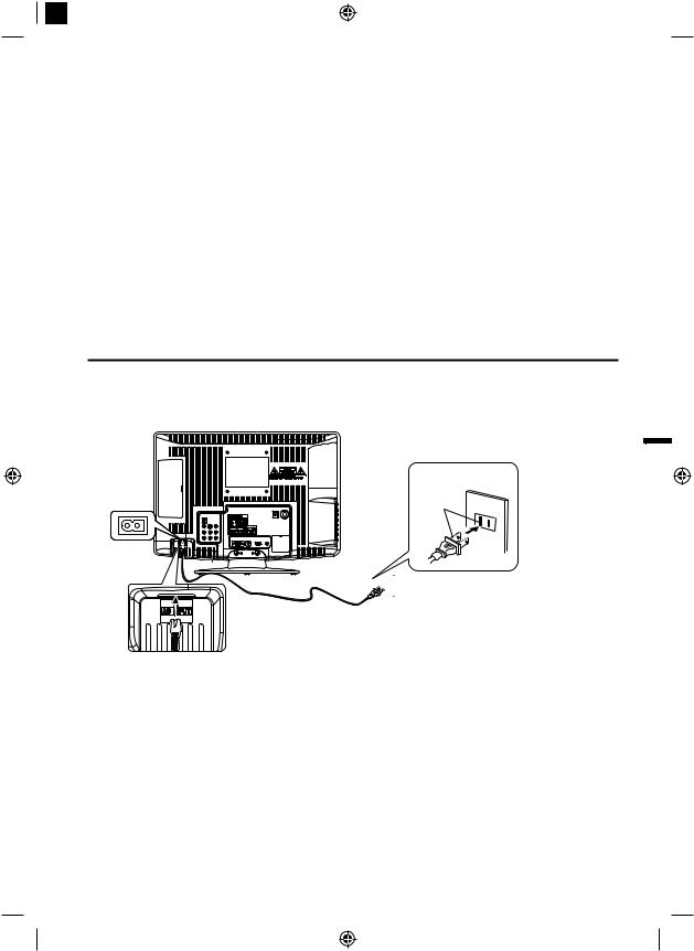
Power source
TO USE AC POWER
1.Connect the AC cord plug into this unit’s AC INPUT jack. 2.Connect the AC cord into an AC outlet.
Wider Hole AC Outlet
and Blade

 AC 120V, 60Hz
AC cord (supplied)
NOTE:
• Please make sure to insert the cord securely at both the LCD TV and the wall outlet.
• The AC cord has a grounding-type AC line plug. If the supplied AC cord does not match your AC outlet, contact a qualified electrician, do not defeat the purpose of a grounding plug.
WARNING:
• DO NOT CONNECT THIS UNIT TO THE POWER USING ANY DEVICE OTHER THAN THE SUPPLIED AC CORD. THIS COULD CAUSE FIRE, ELECTRICAL SHOCK, OR DAMAGE.
• DO NOT USE WITH A VOLTAGE OTHER THAN THE POWER VOLTAGE DISPLAYED. THIS COULD CAUSE FIRE, ELECTRICAL SHOCK, OR DAMAGE.
CAUTION:
• WHEN THIS UNIT IS NOT USED FOR A LONG TIME, (E.G., AWAY ON A TRIP) IN THE INTEREST OF SAFETY, BE SURE TO UNPLUG IT FROM THE AC OUTLET.
• DO NOT PLUG/UNPLUG THE PLUG WHEN YOUR HANDS ARE WET. THIS MAY CAUSE ELECTRICAL SHOCK.
• IF YOU NEED TO REPLACE THE SUPPLIED AC ADAPTER OR AC CORD, THE SPECIFIED ONE IS RECOMMENDED. CONTACT CUSTOMER SERVICE AT 1-800-877-5032.
9
37I0521A_EnSp.indb 9 |
3/24/09 4:19:57 PM |
Contents |
|
Before using your unit |
|
WARRANTY ..................................................... |
2 |
TRADEMARKS................................................. |
3 |
IMPORTANT SAFETY INSTRUCTIONS........... |
5 |
SAFETY PRECAUTIONS ................................. |
7 |
How to attach the stand .................................... |
8 |
How to remove the stand .................................. |
8 |
Features............................................................ |
9 |
Power source .................................................... |
9 |
Contents ......................................................... |
10 |
Parts and functions ......................................... |
11 |
Remote control ............................................... |
12 |
Antenna connections ...................................... |
13 |
Cable TV connections..................................... |
14 |
Connections to other equipment..................... |
15 |
TV operation |
|
Starting setup ................................................. |
18 |
TV operation ................................................... |
18 |
Quick guide for menu operation ...................... |
19 |
Convenience functions ................................... |
20 |
Memorizing channels...................................... |
21 |
Checking the digital-signal strength ................ |
22 |
Labeling channels........................................... |
22 |
Labeling video inputs ...................................... |
22 |
Setting the V-Chip ........................................... |
23 |
Closed Caption ............................................... |
24 |
CC advanced.................................................. |
24 |
Setting the picture size.................................... |
25 |
Additional information |
|
Reception disturbances .................................. |
26 |
Troubleshooting .............................................. |
27 |
Specifications ................................................ |
28 |
10
37I0521A_EnSp.indb 10
3/24/09 4:19:59 PM
Front
Rear
Parts and functions
Left side
Remote sensor
 POWER indicator Red: Standby Green: On
VOLUME +/– buttons
CHANNEL  /
/ buttons
MENU button
INPUT/ENTER button
POWER button
To display the menu screen.
Press MENU button to display the menu screen.
CHANNEL / buttons, VOLUME +/– buttons and INPUT/ENTER button
can be used to select the desired setting during the menu screen operations.
ENGLISH
|
|
|
|
|
|
|
|
|
|
|
|
|
|
|
|
|
|
|
|
|
|
|
|
|
|
|
|
|
|
|
|
|
|
|
|
|
|
|
|
|
|
|
|
|
|
|
|
|
|
|
|
|
|
|
|
|
|
|
|
|
|
|
|
|
|
|
|
|
|
|
|
|
|
|
|
RF (ANT.) IN jack |
|
AC INPUT jack |
|
|
|
|
|
|
|
|
||||
HEADPHONE jack |
|
|
|
|
DIGITAL AUDIO COAXIAL OUT jack |
|||||||
COMPONENT IN jacks |
|
|
|
HDMI IN jack |
||||||||
(Y/Pb/Pr/ AUDIO (L/R)) |
|
|
PC/HDMI AUDIO IN jack |
|||||||||
|
|
VIDEO IN jacks |
PC MONITOR IN jack |
|||||||||
(VIDEO/S-VIDEO/AUDIO (L/R)) |
|
|
|
|
|
|||||||
11
37I0521A_EnSp.indb 11 |
3/24/09 4:19:59 PM |
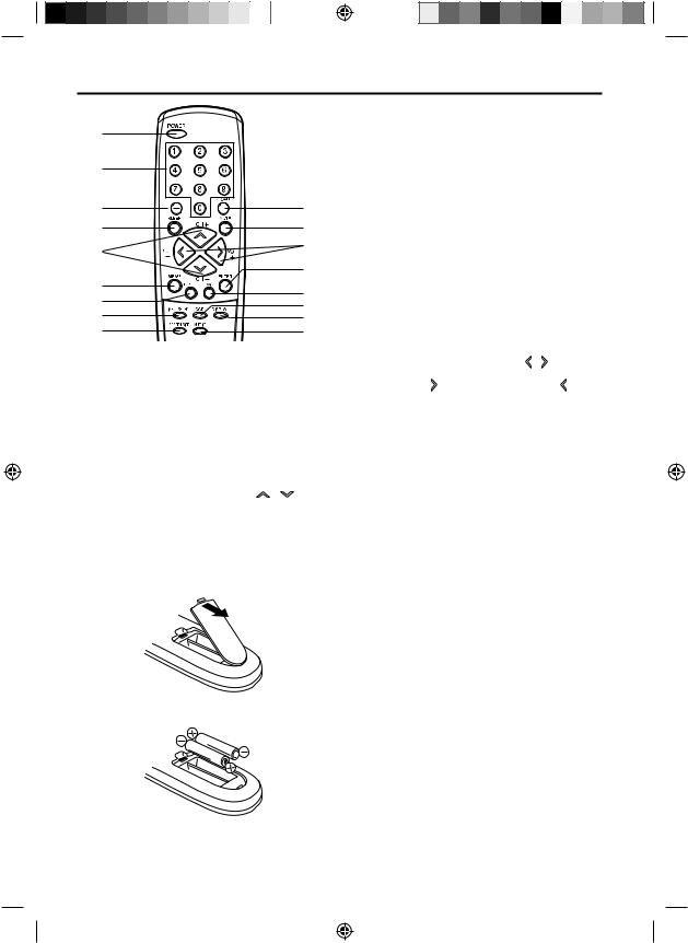
Remote control
1 |
|
|
2 |
|
|
3 |
10 |
|
4 |
11 |
|
5 |
12 |
|
13 |
||
6 |
||
14 |
||
7 |
||
15 |
||
8 |
16 |
|
9 |
17 |
1.POWER Button - Used to turn the power on/off to the LCD TV.
2.Direct Channel Selection Buttons (0-9) - Allows direct access to any channel of the LCD TV.
3.– Button -This button is the “–” button used when selecting digital channels. Also can display the current channel number when viewing the program.
4.SLEEP Button - To set the LCD TV to turn off after a preset amount of time, use the SLEEP button on the remote control.
5.CH (CHANNEL) + / – / CURSOR /
Buttons - Used to operate the menu functions of the LCD TV, and to change the channels of the LCD TV.
Before using the remote control, batteries must first be installed.
HOW TO INSTALL BATTERIES
1.Open the battery compartment cover.
2.Install two “AAA” batteries (supplied).
3.Replace the battery compartment cover.
Use two “AAA” size batteries. The batteries may last approximately one year depending on how much the remote control is used. For best performance, it is recommended that batteries should be replaced on a yearly basis, or when the remote operation becomes erratic. Do not mix old and new batteries or different types.
BATTERY PRECAUTIONS
These precautions should be followed when using batteries in this device:
• Use only the size and type of batteries specified.
• Be sure to follow the correct polarity when installing the batteries as indicated in the battery compartment. Reversed batteries may cause damage to the device.
• Do not mix different types of batteries together (e.g. Alkaline and Carbon-zinc) or old batteries with fresh ones.
• If the device is not to be used for a long period of time, remove the batteries to prevent damage or injury from possible battery leakage.
• Do not try to recharge batteries not intended to be recharged; they can overheat and rupture. (Follow battery manufacturer’s directions.)
12
37I0521A_EnSp.indb 12 |
3/24/09 4:20:02 PM |
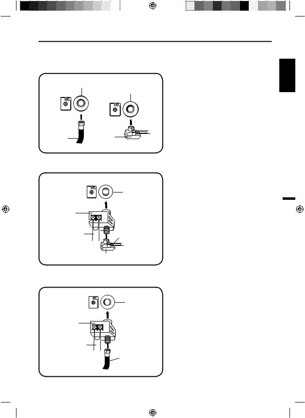
Antenna connections
If you are using an indoor or outdoor antenna, follow the instructions below that correspond to your antenna system. If you are using a Cable TV service, see page 14 for Cable TV connections.
Combination VHF/UHF Antenna (Single 75 ohm cable or 300 ohm twin-lead wire)
Antenna
Jack Antenna
Jack
75 ohm |
300-75 ohm |
Coaxial |
Matching |
Cable |
Transformer |
Connect the 75 ohm cable from the combination VHF/UHF antenna to the antenna jack.
If your combination VHF/UHF antenna has a 300 ohm twin-lead wire, the use of the 300-75 ohm matching transformer may be necessary.
ENGLISH
Combination VHF/UHF Antenna (Separate VHF and UHF 300 ohm twin-lead wires)
Combiner
UHF 300 ohm
Antenna
Jack
VHF 300 ohm
Connect the UHF 300 ohm twin-lead wire to the Combiner (not supplied). Connect the VHF 300 ohm twin-lead wire to the 300-75 ohm Matching Transformer. Attach the Transformer to the Combiner, then attach the Combiner to the Antenna Jack.
300-75 ohm Matching Transformer
Separate VHF/UHF Antennas (75 ohm VHF cable and 300 ohm UHF twin-lead wires)
Antenna
Jack
Combiner
UHF 300 ohm
VHF 75 ohm
Connect the VHF 75 ohm cable and UHF 300 ohm twin-leadwiretothe Combiner(not supplied).Attach the Combiner to the Antenna Jack.
13
37I0521A_EnSp.indb 13 |
3/24/09 4:20:04 PM |
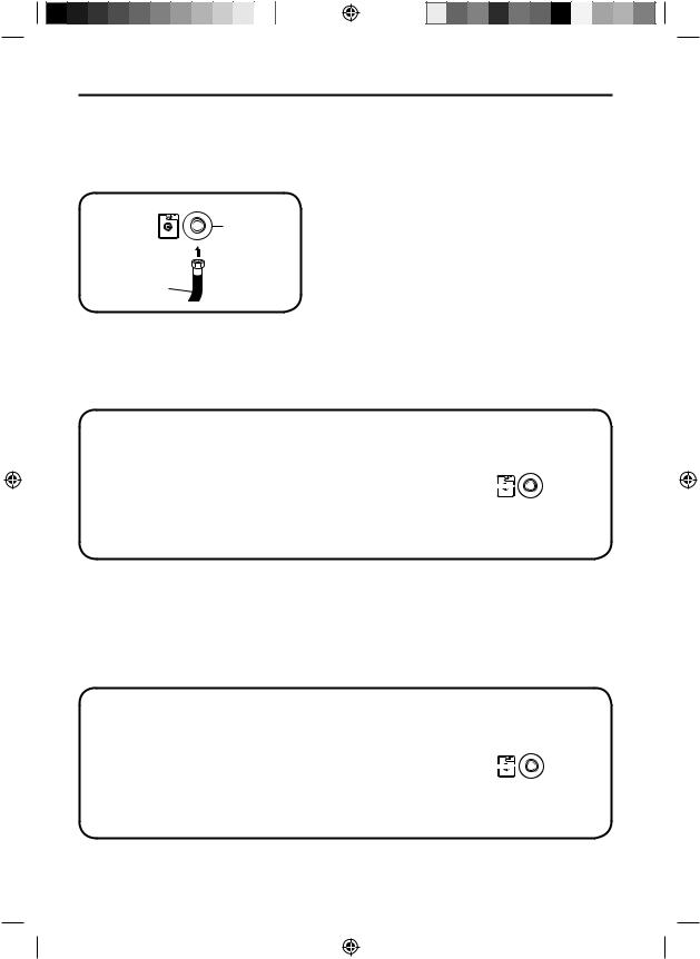
Cable TV connections
This TV has an extended tuning range and can tune most cable channels without using a Cable TV Converter box. Some cable companies offer “premium pay channels” where the signal is scrambled. Descrambling these signals for normal viewing requires the use of a descrambler device which is generally provided by the Cable TV company.
For subscribers to basic Cable TV service
Antenna
Jack
75 ohm Coaxial Cable
For basic Cable TV service not requiring a Converter/ Descrambler box, connect the 75 ohm Coaxial Cable directly to the Antenna Jack on the back of the TV.
For subscribers to scrambled Cable TV service
If you subscribe to a Cable TV service which requires the use of a Converter/Descrambler box, connect the incoming 75 ohm Coaxial Cable to the Converter/Descrambler box. Using another 75 ohm Coaxial Cable, connect the output jack of the Converter/Descrambler box to the Antenna Jack on the TV. Follow the
connections shown below. Set the TV to the output channel of the Converter/Descrambler box (usually channel 3 or 4) and use the Converter/Descrambler box to select channels.
Incoming |
|
Antenna |
75 ohm |
|
|
Cable TV |
|
Jack |
Cable |
Converter/ |
75 ohm Cable to TV |
|
Descrambler |
|
For subscribers to unscrambled Cable TV service with scrambled premium channels
If you subscribe to a Cable TV service in which basic channels are unscrambled and premium channels require the use of a Converter/Descrambler box, you may wish to use a signal Splitter and an A/B Switch box (available from the Cable TV company or an electronics supply store). Follow the connections shown below. With the switch in the “B” position, you can directly tune any nonscrambled channels on your TV. With the switch in the “A” position, tune your TV to the output of the Converter/Descrambler box (usually channel 3 or 4) and use the Converter/Descrambler box to tune scrambled channels.
Incoming |
|
Converter/ |
|
|
75 ohm |
|
|
Antenna |
|
|
Descrambler |
|
||
Cable TV |
|
|
|
Jack |
Cable |
Splitter |
A/B Switch |
A |
75 ohm Cable to TV |
|
B |
14
37I0521A_EnSp.indb 14 |
3/24/09 4:20:06 PM |
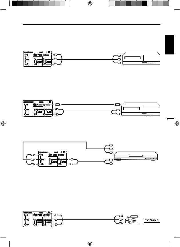
Connections to other equipment
The exact arrangement you use to interconnect various video and audio components to this unit is dependent on the model and features of each component. Check the Owner’s Manual provided with each component for the location of video and audio inputs and outputs.
To connect the LCD TV to a VCR |
|
|
|
Rear of the unit |
|
VCR |
|
To VIDEO/AUDIO IN |
To Video/Audio OUT |
||
|
Video/Audio cord (not supplied)
To connect the LCD TV to a VCR with an S-Video cord
If you connect a VCR with a S-Video cable to the S-VIDEO IN jack on the rear side of the unit, you must also connect the audio cables to the AUDIO IN jacks on the rear of the unit.
The S-Video cable only carries the video signal. The audio signal is separate.
NOTE:
• When the S-Video cable and the standard video cable are connected at the same time, the S-Video cable takes precedence.
Rear of the unit |
|
To S-Video OUT |
VCR |
To S-VIDEO IN |
|||
S-Video cord (not supplied) |
|
||
To AUDIO IN |
Audio cord (not supplied) To Audio OUT |
|
|
ENGLISH
Rear of the unit |
|
Pb |
DVD |
|
Pr |
||
|
|
|
|
|
To component AUDIO IN |
|
|
|
Audio cord |
|
|
To COMPONENT IN |
(not supplied) |
To Audio OUT |
|
|
|
||
|
|
|
NOTE:
• Component Video input of the unit are for use with a device which output 480i/1080i interlaced signals and 480p/720p progressive signals.
To connect the TV to a camcorder, or a TV Game
To playback from a camcorder, connect the camcorder to the unit as shown.
This unit can also be used as a display device for many video games. However, due to the wide variety of signals generated by these devices and subsequent hook-up variations required, they have not all been included in the suggested connection diagrams.You’ll need to consult each component’s Owner’s Manual for additional information.
Rear of the unit
To VIDEO/AUDIO IN To Video/Audio OUT
Video/Audio cord (not supplied) |
or |
|
15
37I0521A_EnSp.indb 15 |
3/24/09 4:20:06 PM |
Connections to other equipment
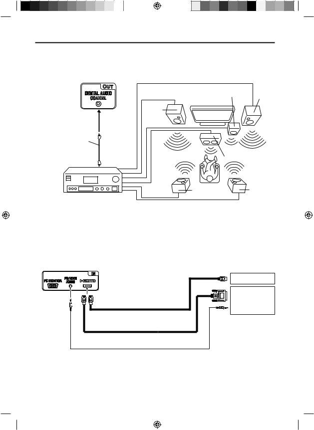
Using an AV Amplifier with built-in digital surround
If you are using an Amplifier with built-in digital surround sound, you can enjoy various audio systems including Dolby Digital Surround audio that sounds just like the movie.
Connect an AV amplifier with built-in Dolby Digital decoder, etc. as shown below.
Rear of the unit
To DIGITAL AUDIO 
COAXIAL OUT
Coaxial digital cable (not supplied)
To Coaxial
Digital Audio IN
AV Amplifier with built-in digital surround decoder as listed above
Front
Subwoofer Speaker
(Right)
TV
Front
Speaker
(Left)
|
Center Speaker |
Surround |
Surround |
Speaker (Left) |
Speaker |
|
(Right) |
NOTE:
• When you are viewing digital broadcast, this unit will not work in conjunction with DTS audio or MPEG audio. There will be no sound output if connected to an AV amplifier with a built-in DTS decoder or MPEG decoder.
To connect a HDMI or a DVI device to the unit
The HDMI input receives digital audio and uncompressed video from a HDMI device or uncompressed digital video from a DVI device.
When you connect to a DVI device with a HDMI-to-DVI adapter cable, it transfers only video signal. Separate analog audio cords required.
Rear of the unit |
|
|
To HDMI out |
|
|
|
|
|
|
|
HDMI device |
|
|
|
or |
To PC/HDMI |
To HDMI |
HDMI cable (type A connector) |
DVI device |
IN |
|
||
AUDIO IN |
|
(not supplied) |
|
|
|
To DVI output |
|
|
|
HDMI - to - DVI adapter cable |
|
|
|
|
|
|
|
(HDMI type A connector) |
|
|
|
(not supplied) |
|
|
Audio cord (not supplied) |
|
|
NOTE:
• When using HDMI to connect your HDMI or DVI devices, you must select the corresponding audio input source (HDMI or DVI) on the menu screen (see page 20). Otherwise you will only see the image with no sound.
• If you connect an external component (cable box, satellite receiver, etc.) to this LCD TV using an HDMI cable or a DVI to HDMI cable, the image will not display if the output resolution of the component is set to 480i. To receive the picture you must change the output resolution on the external component.
Should you require further instruction, please contact the manufacturer of the external component.
16
37I0521A_EnSp.indb 16 |
3/24/09 4:20:07 PM |
Connections to other equipment
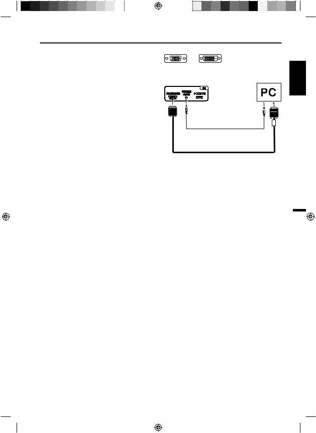
To connect the TV to a PC (Personal Computer)
NOTE: Before connecting any cables, disconnect the AC Power Cords of both the TV and Personal Computer from the AC outlets.
1 Connect an RGB cable from the monitor output (a) on your PC to the RGB connector on the TV and tighten the screws. (Monitor Cable not supplied.)
NOTE:
If Computer has only DVI Output (b), a DVI to RGB converter will be required (converter not included).
2
HINT:
Volume can be adjusted both from the PC and the TV
VOL +/–.
3 Press the INPUT SELECT on your Remote Control to step through signal inputs to select PC.
4 Press the MENU to display the TV’s PC Setup Menu. Select Auto Adjustment.
NOTE:
Power on the TV and any other peripheral equipment before powering on the computer.
(a)(b)
RGB |
DVI JACK |
Rear of the unit
Audio cord (not supplied)
VGA cable (not supplied)
NOTE:
• Save and close all documents, in case computer might need to be restarted.
• Before connecting your computer to your TV, please refer to the following chart to set to a compatible resolution.
• A Refresh Rate value of 60 Hz on your computer is recommended for your TV.
RESOLUTION |
ASPECT RATIO |
REFRESH RATE |
HORIZONTAL |
VERTICAL |
|
|
|
(Hz) |
FREQUENCY |
FREQUENCY (Hz) |
|
|
|
|
(kHz) |
|
|
640 x 480 |
4:3 |
60 |
31.47 |
59.94 |
|
72 |
37.86 |
72.81 |
|||
|
|
75 |
37.50 |
75.00 |
|
720 x 400 |
18:10 |
70 |
31.47 |
70.00 |
|
|
|
56 |
35.16 |
56.25 |
|
800 x 600 |
4:3 |
60 |
37.88 |
60.32 |
|
72 |
48.08 |
72.19 |
|||
|
|
||||
|
|
75 |
46.88 |
75.00 |
|
1024 x 768 |
4:3 |
60 |
48.36 |
60.00 |
|
1280 x 768 |
15:9 |
60 |
47.78 |
59.87 |
|
1280 x 720 |
16:9 |
60 |
45.00 |
60.00 |
|
1360 x 768 |
16:9 |
60 |
47.71 |
60.00 |
ENGLISH
17
37I0521A_EnSp.indb 17 |
3/24/09 4:20:08 PM |
NOTE:
• If you press EXIT in the process of “Auto Setup”, the Starting Setup stops and changes to the normal screen.
• When you make a menu selection, your changes occur immediately.You do not have to press EXIT to see your changes.
• When you are finished programming the menus, press EXIT.
TV operation
1 To turn on the TV, press POWER. (POWER indicator on the front of the unit
changes green. It may take approx. 10 seconds for a picture to appear on screen.)
2 Adjust the volume level by pressing VOL + or – . The volume level will be indicated on the screen by blue bars. As the volume level increases, so do the number of bars. If the volume decreases, the number of blue bars also decreases.
3 Set the Signal Type option to the appropriate position (see “Air/Cable selection” on page 21).
4 Press the Direct Channel Selection (0-9, –) buttons to select the channel.
(If you press only channel number, channel selection will be delayed for a few seconds.)
18
37I0521A_EnSp.indb 18
TO SELECT ANALOG CHANNELS
1-9: Press 1-9 as needed. Example, to select channel 2, press 2, then press
ENTER.
10-99: Press the 2 digits in order. Example, to select channel 12, press 1, 2, then press ENTER.
100-135: Press the 3 digits in order. Example, to select channel 120, press 1, 2, 0, then press ENTER.
TO SELECT DIGITAL CHANNELS
Press the first 3 digits, then press the – button, followed by the remaining number.
Example, to select channel 015-001, press 0, 1, 5, –, 0, 0, 1, then press ENTER.
• If a channel is selected with only audio content, “Audio only” will be displayed on the screen.
• If a channel is selected with a weak digital signal, “Digital channel signal strength is low” will be displayed on the screen.
The same program may be available on either an analog channel or a digital channel.You may choose to watch either format.
• If a channel is selected to which you have not subscribed, “Digital channel is encrypted” will be displayed on the screen.
VHF/UHF/CABLE CHANNELS
Air |
|
Cable |
VHF |
|
VHF |
2-13 |
|
2-13 |
UHF |
STD/HRC/IRC |
|
14-69 |
14-36 |
(A) (W) |
|
37-59 |
(AA) (WW) |
|
60-85 |
(AAA) (ZZZ) |
|
86-94 |
(86) (94) |
|
95-99 |
(A-5) (A-1) |
|
100-135 (100) (135) |
|
|
01 |
(4A) |
NOTE:
• If a channel with no broadcast is selected, the sound will automatically be muted.
• It may take a few seconds for a digital channel picture to appear on screen after being selected.
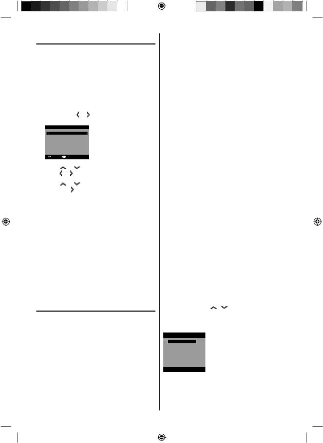
To select the video input source
To view a signal from another device connected to your LCD TV, such as a VCR player, press INPUT SELECT, then press / or corresponding
Number buttons (0-4), then press ENTER.You can select TV, Video, Component, HDMI or PC depending on which input jacks you used to connect your devices.
Source Selection
0.TV
1.Video
2.Component
3.HDMI
4.PC
[0-4]:Select
CH +/-
Press and release CH +/-. The channel automatically stops at the next channel set into memory.
For proper operation, before selecting channels, they should be set into the memory. See “Memorizing channels” on pages 21 and 22.
3/24/09 4:20:08 PM
 Loading...