


DC-MM7000
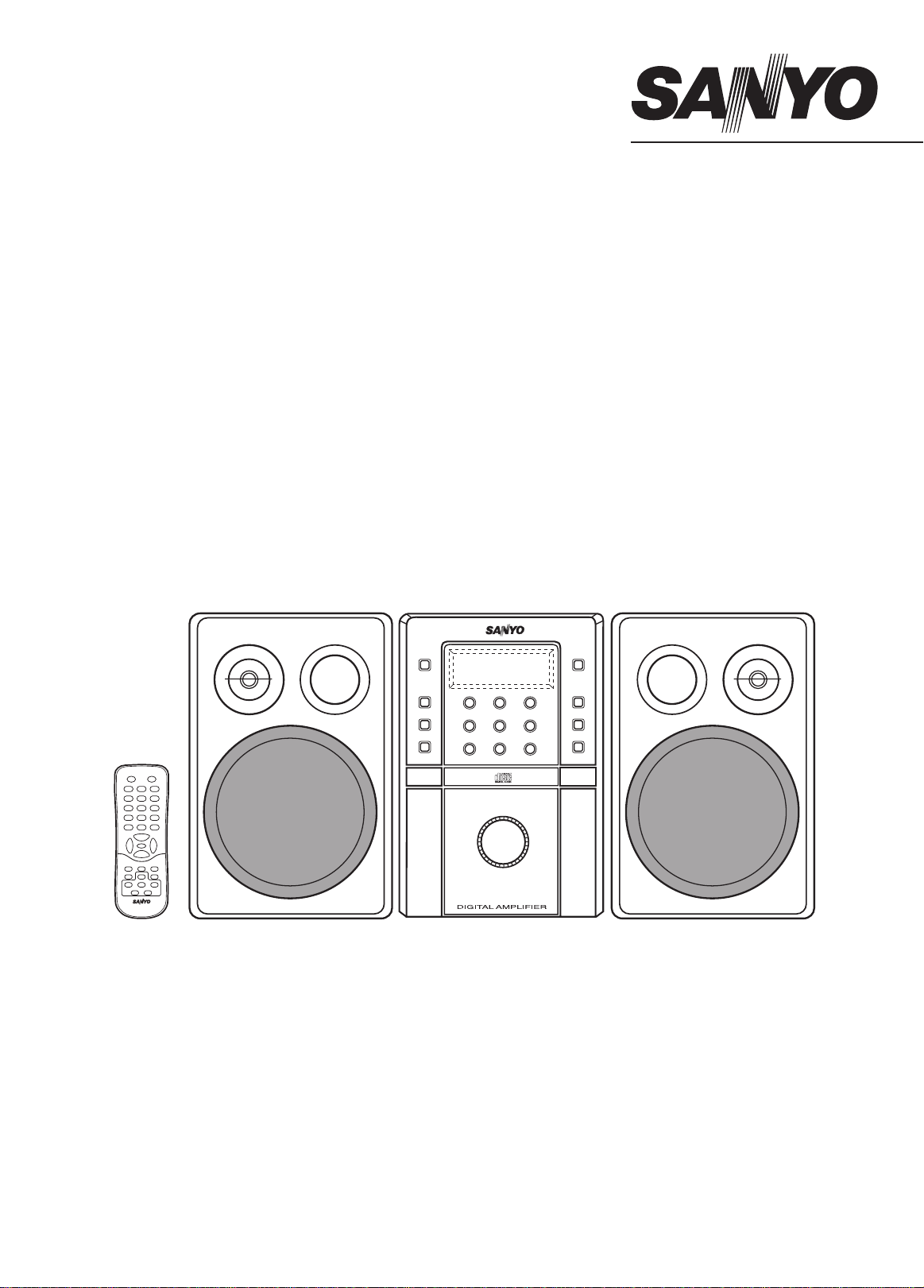
INSTRUCTION MANUAL
Micro Component System
DC-MM7000
SLEEP
FUNCTION
MEMORY OPEN/CLOSE
123
456
789
PRESET SOUND
0
i
VOL VOL
–+
n
TUNER/BAND
–TUNING +
f
e
FMMODE/
a
TAPE
CDRANDOM
REPEAT
dcn
r
j
REMOTECONTROLLER RB-MM7000
z/ON
VOLUME
-+
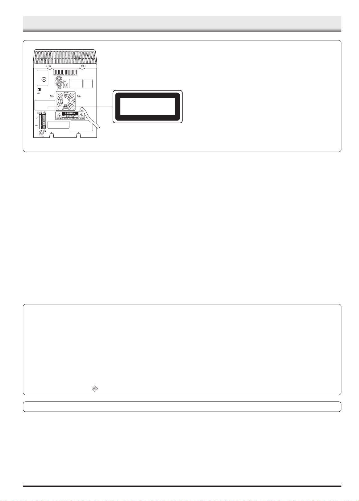
PRECAUTIONS
FM
ANT
CLASS 1 LASER PRODUCT
LUOKAN 1 LASERLAITE
KLASS 1 LASERAPPARAT
CAUTION
THIS PRODUCT CONTAINS A LOW POWER LASER DEVICE,
TO ENSURE CONTINUED SAFETY DO NOT REMOVE ANY
COVERS OR ATTEMPT TO GAIN ACCESS TO THE INSIDE OF
THE PRODUCT.
REFER ALL SERVICING TO QUALIFIED PERSONNEL.
- The apparatus shall not be exposed to dripping or splashing.
- Do not use where there are extremes of temperature (below 5°C
or exceeding 35°C) or where direct sunlight may strike it.
- Because of the CD player’s extremely low noise and wide dynamic range, there might be a tendency to set the volume on the
amplifier unnecessarily high. Doing so may produce an excessively large output from the amplifier which could damage your
speakers.
- When carrying the unit, be sure to remove a disc which may be
inside and turn the power off. Wait at least 10 seconds, then unplug the mains lead from the AC outlet. Carrying the unit with a
disc inside may damage the disc and/or the unit.
IMPORTANT
If the plug supplied with this equipment is not suitable for the socket
outlets in your home it should be cut off and replaced with the correct
type.
Disposal of Plug
If the non rewireable plug is to be cut off, the removed plug should be
disposed of carefully as there is a shock hazard should the plug be
inserted into a live socket.
Replacing Fuse
The detachable fuse cover must be replaced after changing the fuse.
Only a 3A fuse should be used and should comply with BS 1362 and
should carry the ASTA mark
.
- Sudden changes in the ambient temperature may cause condensation to form on the optical lens inside the unit. If this happens,
take out the disc, leave the unit for about 1 hour, and then proceed to operate.
- The system’s speakers use powerful magnets. Do not place timepieces, credit cards, cassette tapes or video tapes, etc. near the
speakers.
- Do not install this equipment in a confined space, such as a book
case or built in cabinet.
- No object filled with liquids, such as vase, shall be placed on the
apparatus.
The wires in the mains lead are coloured in accordance with the
following code.
Blue Neutral
Brown Live
The wires in the mains lead must be connected to the terminals in the
plug as follows:
Wire colour Plug terminal marking
Blue N or Black or Blue
Brown L or Red or Brown
Do not connect either wire to the earth terminal.
If the mains plug contains a fuse this should be 3A, if a plug without
a fuse is used the distribution board fuse should not be greater than
5A.
The unit is not disconnected from the mains unless it is unplugged from the AC outlet.
-1-
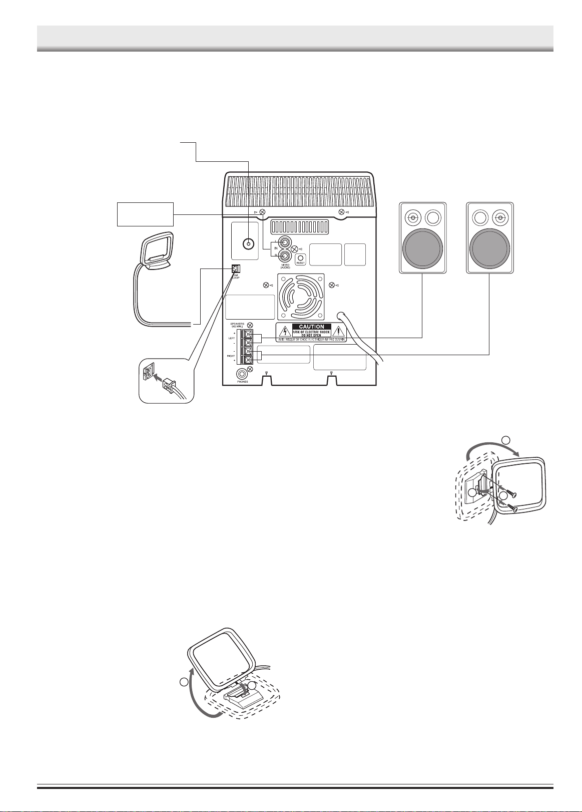
FM aerial
CONNECTIONS
Video/Auxiliary equipment
AM loop aerial
Note:
- Do not connect the mains lead to an AC outlet until all connections
have been made.
- The system is not completely disconnected from the mains when
the z/ON button is set to the z position.
FM
ANT
To an AC outlet
Unwind the aerial wires, then connect
them to the AM LOOP terminals. Place
the loop aerial in a position which yields
the best AM reception, or attach it to a
wall or other surface as shown in figure.
R ch speakerL ch speaker
1
Speakers
When connecting the speakers, make sure that (+) and (-) polarities
are matched properly. Otherwise, the sound may appear to be lacking in the bass range and stability.
Connect the speaker wire with the stripe to the red terminal (+) and
the other wire to the black terminal (-).
Aerial
Extend the aerial wire as straight as possible and, while listening to the
sound from the system, secure it in a position which yields minimal
distortion and noise.
AM loop aerial
Assemble the loop aerial as shown in figure.
1
2
If you have difficulty inserting the AM
loop aerial cable connector, turn it over
and reinsert it.
Note:
To minimize noise, the speaker, mains
and any other leads should not come
close to the FM aerial lead and AM loop
aerial. Do not place the aerial leads
close to the system.
3
Screws (not supplied)
2
Video/Auxiliary equipment
Connect audio leads (not supplied) from the audio output sockets of a
video/auxiliary equipment to the VIDEO (AUDIO) sockets.
Headphones
Connect stereo headphones (not supplied) to the PHONES socket (the
rear of the unit) for monitoring or for private listening. The speakers are
automatically disconnected when headphones are connected.
-2-
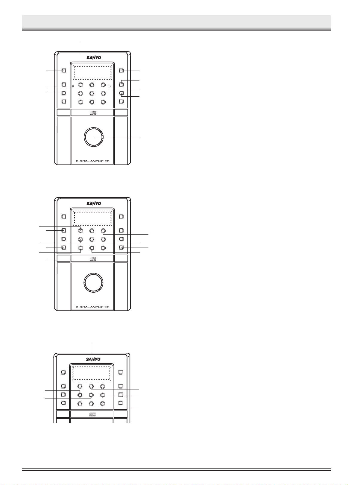
CONTROLS
2
General
1. Power button (z/ON)
1
3
4
9
8
VOLUME
-+
5
6
7
2. Display
3. Ecology mode/Clock/Timer button (ECO/CLOCK/TIMER)
4. Sound preset button (SOUND PRESET)
5. Remote sensor (IR)
6. Bass expander button (BASS)
7. Volume control (VOLUME)
8. Memory button (MEMORY)
9. Standby indicator
CD player/Tuner
1. Tuner function/Band select button (TUNER/BAND)
1
10
9
8
7
2
3
4
5
6
VOLUME
-+
2. Play/Pause button ( CD I )
3. Stop button ( N )
4. Disc tray open/close button (CD OPEN/CLOSE)
5. Repeat button (REPEAT)
6. Disc tray
7. Random play button (RANDOM)
8. FM mode button (FM MODE)
9. Skip/Search/Tuning buttons (F/TUNING -, E/TUNING +)
10. Preset tuning button (TUNER PRESET)
1
Cassette deck
1. Cassette holder
2. Tape function/Play button (TAPE A)
3. Stop button ( N )
4. Record/Record pause button ( J )
5. Fast forward button ( E /TUNING +)
6
5
2
3
6. Rewind button ( F /TUNING –)
4
-3-
 Loading...