


UE48H6800AW
Table of contents
 Loading...
LED TV
SERVICE
Manual
LED TV Contents
1. Precautions
2. Product specications
3. Disassembly and Reassembly
4. Troubleshooting
5. Wiring Diagram
UE**H6800AW
Chassis : U8DD
Model : UE48H6800AW
UE55H6800AW

Contents
1. Precautions ...................................................................................................................1-1
1-1. Safety Precautions ..............................................................................................................1-1
1-1-1. Warnings ...................................................................................................................1-1
1-1-2. Servicing the LED TV ...............................................................................................1-1
1-1-3. Fire and Shock Hazard .............................................................................................1-1
1-1-4. Product Safety Notices .............................................................................................1-2
1-2. Servicing Precautions ..........................................................................................................1-3
1-2-1. General Servicing Precautions ................................................................................. 1-3
1-3. Static Electricity Precautions ...............................................................................................1-4
1-4. Installation Precautions .......................................................................................................1-5
2. Product Specications.................................................................................................2-1
2-1. Product information .............................................................................................................2-1
2-2. Product specication ...........................................................................................................2-2
2-2-1. Detailed Specications ............................................................................................. 2-2
2-2-2. Feature & Specications ........................................................................................... 2-6
2-3. Accessories .........................................................................................................................2-7
2-4. Viewing the Functions .........................................................................................................2-8
3. Disassembly and Reassembly ....................................................................................3-1
3-1. Disassembly and Reassembly ............................................................................................3-1
4. Troubleshooting ...........................................................................................................4-1
4-1. Troubleshooting ...................................................................................................................4-1
4-1-1. Previous Check ........................................................................................................4-1
4-2. How to Check Fault Symptom .............................................................................................4-3
4-2-1. NO Power .................................................................................................................4-3
4-3. Factory Mode Adjustments ..................................................................................................4-6
4-3-1. Detail Factory Option ................................................................................................4-6
4-3-2. Entering Factory Mode ............................................................................................. 4-7
4-3-3. Factory Data .............................................................................................................4-8
4-4. White Balance ...................................................................................................................4-23
4-4-1. Calibration ..............................................................................................................4-23
4-4-2. Service Adjustment ................................................................................................. 4-23
4-4-3. Adjustment .............................................................................................................. 4-24
4-5. Software Upgrade ..............................................................................................................4-25
4-5-1. How to Check the Software Version .......................................................................4-25
4-5-2. How to Upgade Software ........................................................................................ 4-26

5. Wiring Diagram .............................................................................................................5-1
5-1. Wiring Diagram ....................................................................................................................5-1
5-2. Connector ............................................................................................................................5-6
5-3. Connector Functions ...........................................................................................................5-9

This Service Manual is a property of Samsung Electronics Co.,Ltd.
Any unauthorized use of Manual can be punished under applicable
International and/or domestic law.
© 2014 Samsung Electronics Co.,Ltd.
All rights reserved.
Printed in Korea
Follow these safety, servicing and ESD precautions to prevent damage and to protect against potential hazards such as
electrical shock.
1-1-1. Warnings
WARNING
For continued safety, do not attempt to modify the circuit board.
Disconnect the AC power and DC power jack before servicing.
1-1-2. Servicing the LED TV
When servicing the LED TV, Disconnect the AC line cord from the AC outlet.1.
It is essential that service technicians have an accurate voltage meter available at all times. Check the calibration of this 2.
meter periodically.
1-1-3. Fire and Shock Hazard
Before returning the monitor to the user, perform the following safety checks:
Inspect each lead dress to make certain that the leads are not pinched or that hardware is not lodged between the 1.
chassis and other metal parts in the monitor.
Inspect all protective devices such as nonmetallic control knobs, insulating materials, cabinet backs, adjustment and 2.
compartment covers or shields, isolation resistorcapacitor networks, mechanical insulators, etc.
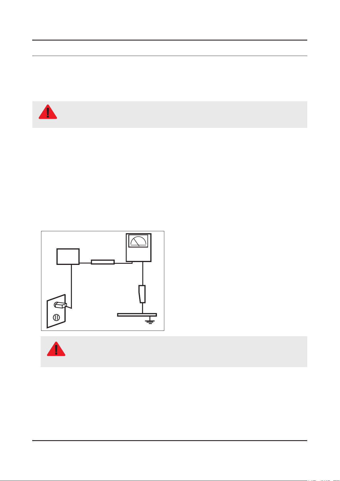
Leakage Current Hot Check:3.
DEVICE
UNDER
TEST
(READING SHOULD)
NOT BE ABOVE 0.5mA
LEAKAGE
CURRENT
TESTER
TEST ALL
EXPOSED METAL
SURFACES
2-WIRE CORD
ALSO TEST WITH
PLUG REVERSED
(USING AC ADAPTER
PLUG AS REQUIRED)
EARTH
GROUND
WARNING
Do not use an isolation transformer during this test.
Use a leakage current tester or a metering system that complies with American National Standards
Institute (ANSI C101.1, Leakage Current for Appliances), and Underwriters Laboratories (UL
Publication UL1410, 59.7).
With the unit completely reassembled, plug the AC line cord directly into a 120V AC outlet. With the unit’s AC switch rst 4.
in the ON position and then OFF, measure the current between a known earth ground (metal water pipe, conduit, etc.)
and all exposed metal parts, including: metal cabinets, screwheads and control shafts.
The current measured should not exceed 0.5 milliamp.
Reverse the power-plug prongs in the AC outlet and repeat the test.
1-1
1. Precautions
1. Precautions
1-1. Safety Precautions

1-2
1. Precautions
1-1-4. Product Safety Notices
Some electrical and mechanical parts have special safetyrelated characteristics which are often not evident from visual
inspection. The protection they give may not be obtained by replacing them with components rated for higher voltage,
wattage, etc. Parts that have special safety characteristics are identied by on schematics and parts lists. A substitute
replacement that does not have the same safety characteristics as the recommended replacement part might create
shock, re and/or other hazards. Product safety is under review continuously and new instructions are issued whenever
appropriate.
WARNING
An electrolytic capacitor installed with the wrong polarity might explode.
CAUTION
Before servicing units covered by this service manual, read and follow the Safety Precautions section of
this manual.
NOTE
If unforeseen circumstances create conict between the following servicing precautions and any of the
safety precautions, always follow the safety precautions.
1-2-1. General Servicing Precautions
Always unplug the unit’s AC power cord from the AC power source and disconnect the DC Power Jack before 1.
attempting to: (a) remove or reinstall any component or assembly, (b) disconnect PCB plugs or connectors, (c) connect
a test component in parallel with an electrolytic capacitor.
Some components are raised above the printed circuit board for safety. An insulation tube or tape is sometimes used. 2.
The internal wiring is sometimes clamped to prevent contact with thermally hot components. Reinstall all such elements
to their original position.
After servicing, always check that the screws, components and wiring have been correctly reinstalled. Make sure that 3.
the area around the serviced part has not been damaged.
Check the insulation between the blades of the AC plug and accessible conductive parts (examples: metal panels, input 4.
terminals and earphone jacks).
Insulation Checking Procedure: Disconnect the power cord from the AC source and turn the power switch ON. Connect 5.
an insulation resistance meter (500 V) to theblades of the AC plug. The insulation resistance between each blade of the
AC plug and accessible conductive parts (see above) should be greater than 1 megohm.
Always connect a test instrument’s ground lead to the instrument chassis ground before connecting the positive lead; 6.
always remove the instrument’s ground lead last.
1-3
1. Precautions
1-2. Servicing Precautions
Some semiconductor (solid state) devices can be easily damaged by static electricity. Such components are commonly
called Electrostatically Sensitive Devices (ESD). Examples of typical ESD are integrated circuits and some eld-effect
transistors. The following techniques will reduce the incidence of component damage caused by static electricity.
Immediately before handling any semiconductor components or assemblies, drain the electrostatic charge from your 1.
body by touching a known earth ground. Alternatively, wear a discharging wrist-strap device. To avoid a shock hazard,
be sure to remove the wrist strap before applying power to the monitor.
After removing an ESD-equipped assembly, place it on a conductive surface such as aluminum foil to prevent 2.
accumulation of an electrostatic charge.
Do not use freon-propelled chemicals. These can generate electrical charges sufcient to damage ESDs.3.
Use only a grounded-tip soldering iron to solder or desolder ESDs.4.
Use only an anti-static solder removal device. Some solder removal devices not classied as “anti-static” can generate 5.
electrical charges sufcient to damage ESDs.
Do not remove a replacement ESD from its protective package until you are ready to install it. Most replacement ESDs 6.
are packaged with leads that are electrically shorted together by conductive foam, aluminum foil or other conductive
materials.
Immediately before removing the protective material from the leads of a replacement ESD, touch the protective material 7.
to the chassis or circuit assembly into which the device will be installed.
CAUTION
Be sure no power is applied to the chassis or circuit and observe all other safety precautions.
Minimize body motions when handling unpackaged replacement ESDs. Motions such as brushing clothes together, or 8.
lifting your foot from a carpeted oor can generate enough static electricity to damage an ESD.
1-4
1. Precautions
1-3. Static Electricity Precautions
For safety reasons, more than a people are required for carrying the product.1.
Keep the power cord away from any heat emitting devices, as a melted covering may cause re or electric shock.2.
Do not place the product in areas with poor ventilation such as a bookshelf or closet. The increased internal temperature 3.
may cause re.
Bend the external antenna cable when connecting it to the product. This is a measure to protect it from being exposed 4.
to moisture. Otherwise, it may cause a re or electric shock.
Make sure to turn the power off and unplug the power cord from the outlet before repositioning the product. Also check 5.
the antenna cable or the external connectors if they are fully unplugged. Damage to the cord may cause re or electric
shock.
Keep the antenna far away from any high-voltage cables and install it rmly. Contact with the highvoltage cable or the 6.
antenna falling over may cause re or electric shock.
When installing the product, leave enough space (0.4m) between the product and the wall for ventilation purposes. 7.
A rise in temperature within the product may cause re.
If an equipment is provided with a replaceable battery, and if replacement by an incorrect type could result in an 8.
explosion (for example, with some lithium batteries), the following applies:
CAUTION
Risk of explosion if battery is replaced by an incorrect type dispose of used batteries according to •
the instructions.
Do not dispose of batteries in a re.•
Do not short circuit, disassemble or overheat the batteries.•
Danger of explosion if battery is incorrectly replaced. Replace only with the same or equivalent •
type.
Do not be exposed to excessive heat such as sunshine, re or the like.•
1-5
1. Precautions
1-4. Installation Precautions
2-1
2. Product specications
2. Product Specications
2-1. Product information
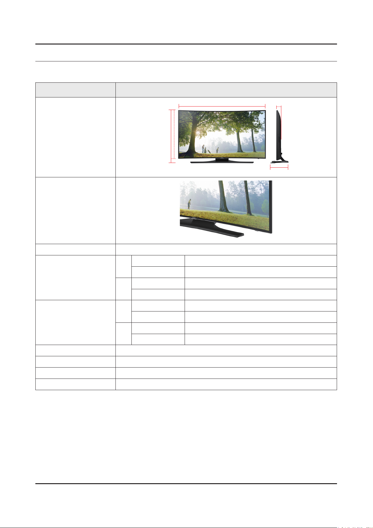
Model UE**H6800AW
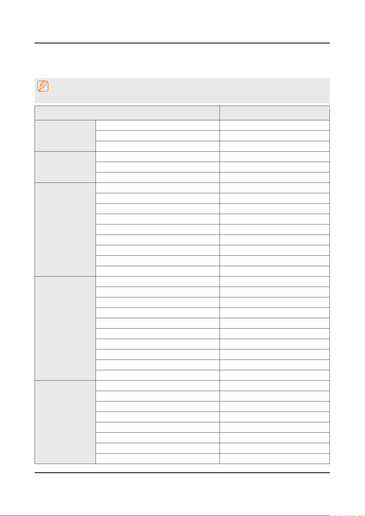
Front View
W
D
* W : Width H : High D : Depth
H
Detail View
Front Color Black
Dimensions
(W x H x D)
48"
Body 1078.6 X 625.9 X 79.2 mm
With stand 1078.6 X 673.1 X 294.9 mm
55"
Body 1232.8 X 713.3 X 90.6 mm
With stand 1232.8 X 762.0 X 294.9 mm
Weight
48"
Body 13.5 kg
With stand 16.4 kg
55"
Body 17.7 kg
With stand 20.6 kg
Panel Type Anti Glare
Internal Memory 4GB
DDR 1.25GB
Feature 3D / SMART HUB / DLNA / Full browsing / Wired IR Blastet
2-2
2. Product specications
2-2. Product specication
2-2-1. Detailed Specications
NOTE
Design and specications are subject to change without prior notice.
Item UE**H6800AWXXH
General Information
Product LED
Series 6
Country HUNGARY
Display
Inch 48" / 55"
Resolution 1,920 x 1,080
Ultra Clear Panel Yes
Video
Picture Engine 3D HyperReal Engine
Clear Motion Rate 600
Micro Dimming Micro Dimming
Precision Black (Local Dimming) No
Wide Color Enhancer (Plus) Yes
Wide Color Gamut N/A
Color Accuracy N/A
Auto Depth Enhancer N/A
Film Mode Yes
Audio
Dolby MS10 / MS110 Dolby MS10
DTS Studio Sound / DNSe+ DTS Studio Sound
DTS Premium Sound / DTS Premium Sound 5.1 DTS Premium Sound 5.1
3D Sound Yes
Auto Volume Leveler Yes
Sound Customizer No
Sound Output (RMS) 40W(Left:10W, Right:10W, Woofer:20W)
Speaker Type Down Firing + New Waveguide
Woofer Yes
HD Audio No
Smart TV
Smart Hub Yes
Samsung SMART TV Yes
On TV Yes (15 European Countries)
Movies & TV Shows Yes (9 European Countries)
Multimedia Yes
Apps Yes
Game Yes (7 European Countries)
Fitness Yes
2-3
2. Product specications
Item UE**H6800AWXXH
Smart TV
Kids Yes
Multi-Screen (Dual / Quad Screen) No
Skype™ on Samsung TV Ready
Web Browser Yes
Smart Interaction
Voice Interaction No
Voice Control No
Camera Built-in No
Face recognition No
Motion control No
Smart Convergence
Contents Streaming Yes
Screen Mirroring Yes
Samsung SMART View Yes
Smart Home Yes (FR,DE,ES)
Easy Pin pairing Yes
Tuner/Broadcasting
Twin Tuner No
CI/CI+/2CI+ CI+ (1.3)
DTV Tuner DVB-T/C
Analog Tuner Yes
MHP / MHEG / HbbTV / ACAP / GINGA / OHTV HbbTV (ES,PT,FR,BE,NL,LU,CH,PL,CZ)
Connectivity
HDMI 4
USB 3
Component In (Y/Pb/Pr) 1
Composite In (AV) 1 (Common Use for Component Y)
Ethernet (LAN) Yes
Headphone Yes
Digital Audio Out (Optical) 1
RF In (Terrestrial / Cable input) 1/1(Common Use for Terrestrial)/0
Ex-Link ( RS-232C ) N/A
IR Out Yes
CI Slot 1
Scart 1
MHL 3 No
One Connect (Jack) No
WiFi Direct Yes
HDMI 1.4 3D Auto Setting Yes
HDMI 1.4 A/Return Ch. Support Yes
InstaPort S (HDMI quick switch) No
Wireless LAN Adapter Support No
2-4
2. Product specications
Item UE**H6800AWXXH
Connectivity
Wireless LAN Built-in Yes
Anynet+ (HDMI-CEC) Yes
Design
Design Curved
Bezel Type VNB
Front Color Black
Light Effect (Deco) N/A
Stand Type T-shape
Swivel (Left/Right) No
Additional Feature
Samsung 3D Yes
3D Converter Yes
Instant On No
Quad Core+ No
Accessibility
TTS,Zoom (10 European Countries) /
Zoom (Others)
Auto Power Off Yes
Clock&On/Off Timer Yes
Sleep Timer Yes
BD Wise Plus Yes
Caption (Subtitle) Yes
Channel List USB-Clone Yes
ConnectShare™ (USB 2.0) Movie
Football Mode Advanced
Embeded POP Yes
EPG Yes
PVR Ready Yes
Game Mode Yes
Multiroom Compatible No
OSD Language 27 European Languages
Picture-In-Picture Yes
BT HID Built-in Yes
USB HID Support Yes
Smart Evolution Support No
TV SoundConnect Yes
Teletext (TTXT) Yes
Time Shift Yes
Eco Feature
Eco Sensor Yes
Energy Efciency Class A+
Mercury Content 0.0mg
Lead Presence Yes
2-5
2. Product specications
Item UE**H6800AWXXH
Accessory
3D Active Glasses (Included) No
Remote Controller Model TM1250A
Batteries (for Remote Control) Yes
Samsung Smart Touch Control (Included) No
Ultra Slim Wall Mount Supported No
Mini Wall Mount Supported Yes
Vesa Wall Mount Supported Yes
Floor Stand Support Yes
TV Camera (Included) No
IR Extender Cable (Included) Yes
Wireless Keyboard (Included) No
Wireless LAN Adaptor (Included) No
User Manual Yes
E-Manual Yes
Power Cable Yes
Slim Gender Cable No
2-6
2. Product specications
2-2-2. Feature & Specications
Feature
Digital-TV, RF, 4-HDMI, 1-Component,1-A/V, 3-USB2.0, LAN, built-in WIFI•
PIP(in HDMI 1, 2, 3, 4 Component and Sub picture is available only in TV mode(DTV/ATV))•
CMR 720•
Dolby Digital Plus Pulse, DTS Premium Sound 5.1, DTS Studio Sond•
Specications
Model UE**H6800AW
Item Description
Screen Size (Diagonal) 48 inches 55 inches
LCD Panel FHD 120Hz
Scanning Frequency Horizontal : 31 kHz ~ 80 kH
Vertical : 56 Hz ~ 75 Hz
Display Resolution 1920 X 1080
Input Signal Analog 0.7 Vp-p ± 5% positive at 75Ω, internally terminated
Input Sync Signal H/V Separate, TTL, P. or N.
Maximum Pixel Clock Rate 138 MHz
AC Power Voltage & Frequency AC220-240V 50/60Hz
Environmental Considerations Operating Temperature : 50˚F ~ 104˚F (10˚C ~ 40˚C)
Operating Humidity : 10% ~ 80%, non-condensing
Storage Temperature : -4˚F ~ 113˚F (-20˚C ~ 45˚C)
Storage Humidity : 5% ~ 95%, non-condensing
Sound (Output) 40W (Left:10W, Right:10W, Woofer:20W)
Note : AllShare, SMART Hub, Web Browser, USB HID, Wired IR Blaster
2-7
2. Product specications
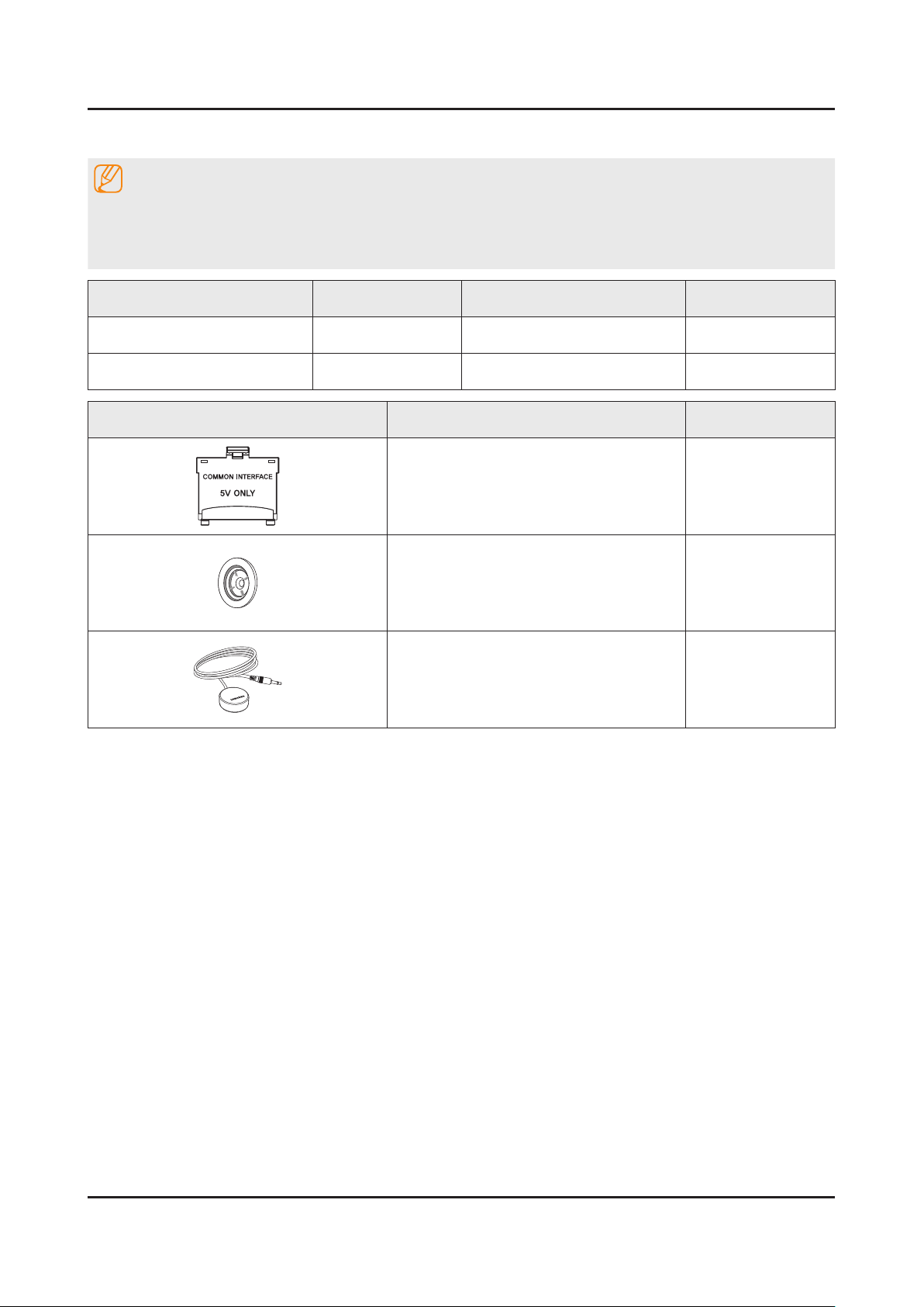
2-3. Accessories
NOTE
The items’ colors and shapes may vary depending on the model.•
Cables not included in the package contents can be purchased separately.•
The part code for some accessories may differ depending on your region.•
Product Code. No Product Code. No
Remote Control• BN59-01178B Power Cord• 3903-000525
Batteries (AAA x 2)• 4301-000103 User Manual• BN68-06539C
Image Product Code. No
CI Card Adapter• 3709-001791
Hoder Ring• BN61-07295A
IR Extender Cable• BN96-31644A

2-8
2. Product specications
2-4. Viewing the Functions
Using the Remote Control
Turns the Set-top box on and off.
Displays and selects available video
sources.
Cuts off the sound temporarily.
Brings up
Smart Hub
applications. Refer
to the e-Manual chapter, Smart Features
>
Smart Hub
.
Changes channels.
Exits the menu.
Displays the EPG (Electronic Programme
Guide).
Displays information on the TV screen.
Turns the TV on and off.
Gives direct access to channels.
Adjusts the volume.
Displays channel lists.
Alternately selects Teletext ON Double,
Mix or OFF.
: Enable
Football Mode
for an optimal
sports viewing experience.
SEARCH
: Press this button to use the
search window.
KEYPAD
: With the virtual remote control
on the screen, you can easily enter digits,
control content, and use functions.
E-MANUAL
: Displays the
e-Manual
.
P.SIZE
: Change the picture size.
AD/SUBT.
: Displays the
Accessibility
Shortcuts
.
Returns to the previous channel.
Opens the OSD (Menu).
Quickly selects frequently used functions.
Returns to the previous menu.
Use these buttons according to the
directions on the TV screen.
Use these buttons with specific features.
Use these buttons according to the
directions on the TV screen.
Moves the cursor, selects the on-screen
menu items, and changes the values
seen on the TV's menu.
3-1
3. Disassembly and Reassemble
3. Disassembly and Reassembly
This section of the service manual describes the disassembly and reassembly procedures for the LED TV.
WARNING
This LED TV contains electrostatically sensitive devices. Use caution when handling these components.
3-1. Disassembly and Reassembly
CAUTION
Disconnect the LED TV from the power source before disassembly.1.
Follow these directions carefully; never use metal instruments to pry apart the cabinet.2.
If there is no additional coment, it is same for all inches.3.
48" / 55"
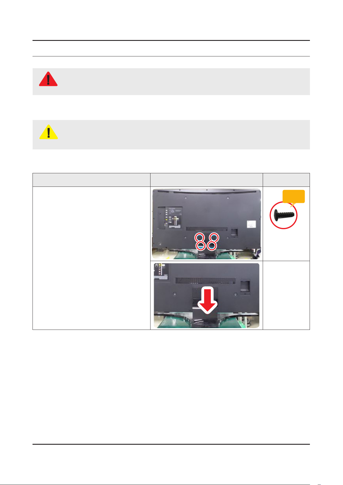
Description Picture Description Screws
1
Remove screws from the Stand.
Torque :
9~ 11Kgf.cm.
6001-001782
Remove stand.
3-2
3. Disassembly and Reassemble
Description Picture Description Screws
2
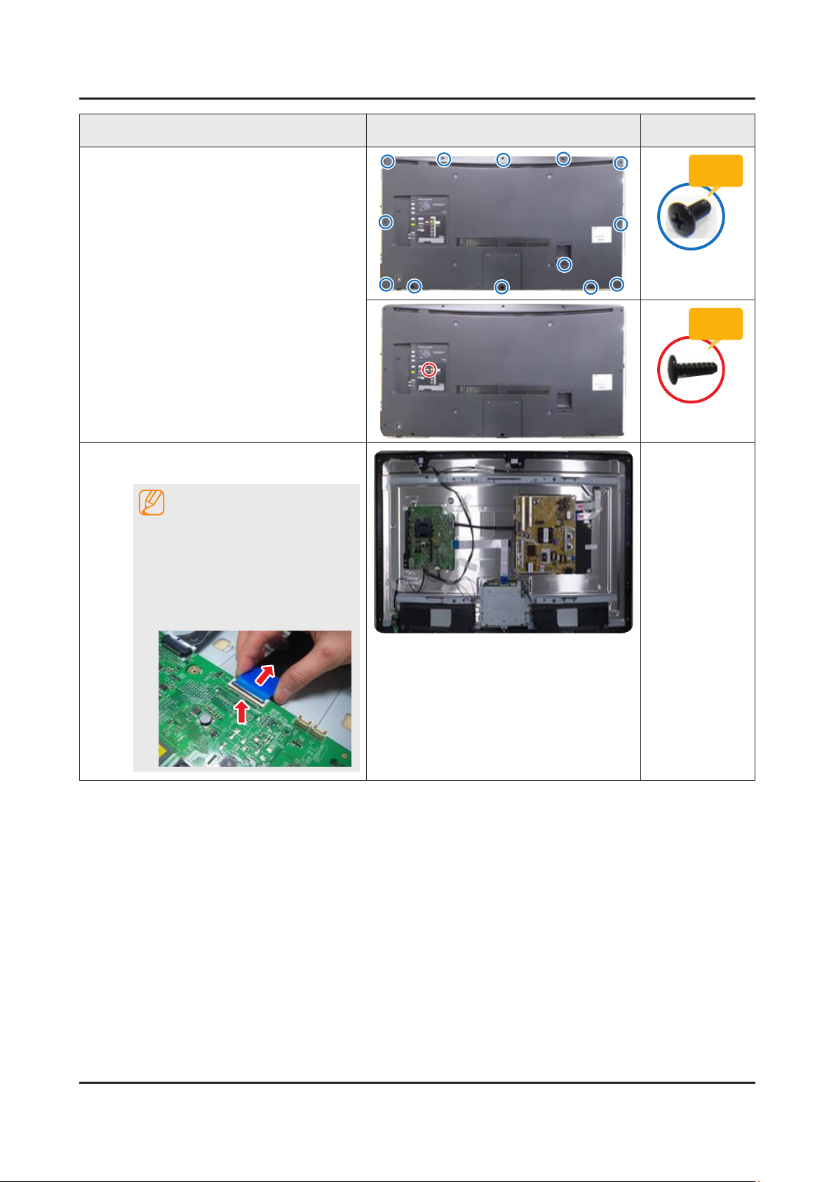
Remove the screws of rear-cover.
(In this step, Two types of screws are
used.)
48" : 13EA / 1EA•
55" : 17EA / 1EA•
Torque :
7~ 8Kgf.cm.
6001-002755
Torque :
9~ 11Kgf.cm.
6001-001782
3
Remove the Main Board and the
Power Board.
NOTE
Applied to Double locking.
Flip up the locking tab on top of the 1.
connector.
Squeeze the edge of the connector 2.
to release the second tab lock and
gently pull the connector away.
3-3
3. Disassembly and Reassemble
Description Picture Description Screws
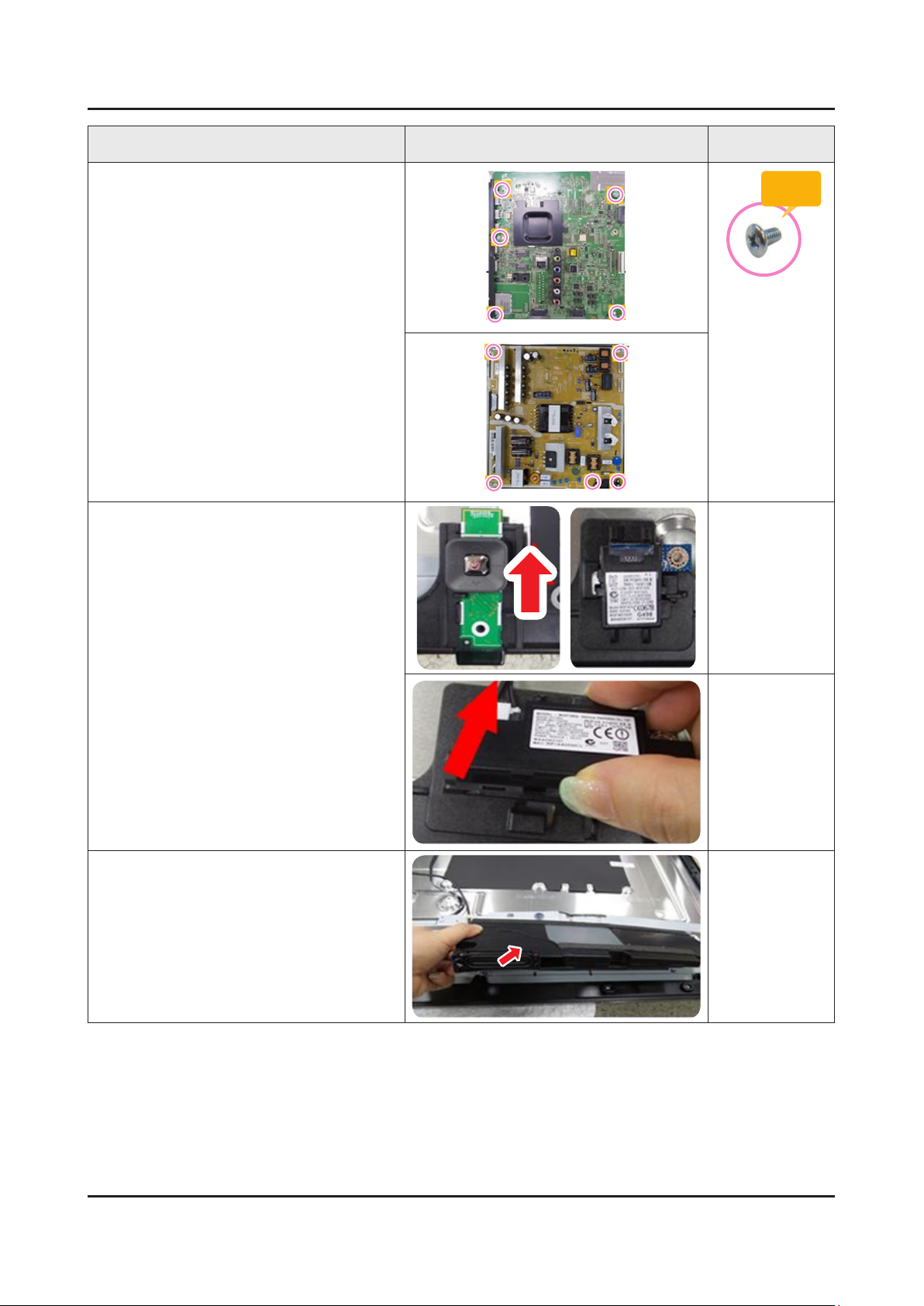
4
Remove the screws of main board.
Torque :
7~ 8Kgf.cm
6001-002756
Remove the screws of IP board.
Remove the IP board.
5
Remove Function Assy, WIFI and BT
Module.
6
Remove the Speakers.(R/L)
3-4
3. Disassembly and Reassemble
Description Picture Description Screws
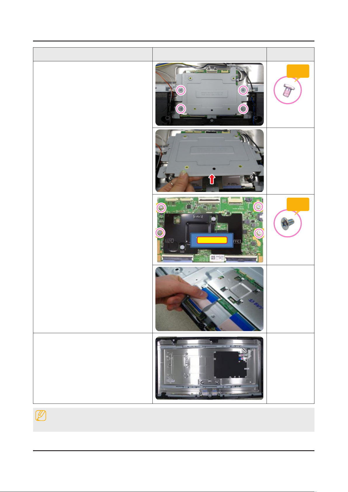
7
Remove the screws of T-con.
Torque :
7~8Kgf.cm
6001-003075
T-con Board
Torque :
7~ 8Kgf.cm
6001-002653
Unlock the locking of T-con cable.
8
Completed disassembly.
Panel•
NOTE
Reassembly procedures are in the reverse order of disassembly procedures.
4. Rozwiązywanie problemów
4.1
4. Rozwiązywanie problemów
4.1. Przygotowanie
1. Sprawdź połączenie przewodów:
Czy jakieś przewody są przypalone lub uszkodzone
Czy jakiejś przewody są odłączone lub luźne
Czy przewody są połączone zgodnie ze schematem
2. Sprawdź zasilanie płyty głównej
3. W jaki sposób rozpoznać czy problem jest powodowany przez Płytę Główną czy Moduł T-CON
Brak obrazu: Podświetlenie jest uruchomione, ale brak obrazu a wskaźnik na z przodu
telewizora miga szybciej niż przy normalnym uruchamianiu.
Zniekształcenia obrazu: Sprawdź ‘Inner Patterns - Wewnętrzne obrazy kontrolne’
- Dla wszystkich trybów
X12
Po FOX_FT1 FRC
Obraz
Problem
Jest w porządku
Jest w porządku
Nie jest w porządku
Płyta główna lub źródło
sygnału
Nie jest w porządku
Jest w porządku
Nie jest w porządku
Płyta główna
Nie jest w porządku
Nie jest w porządku
Nie jest w porządku
Płyta główna lub przewód
LVDS lub T-CON lub Panel
- Tylko dla trybu HDMI (dodatkowe sprawdzenie)
HDMI
Obraz
Problem
Jest w porządku
Nie jest w porządku
Brak problemu po sprawdzeniu układu sterującego
HDMI, źródła sygnału HDMI i złącza HDMI
Nie jest w porządku
Nie jest w porządku
Brak problemu przed sprawdzeniem układu
sterującego HDMI, obrazów testowych(pattern) X12
lub przewodu LVDS lub T-CON
Przewód LVDS
Przewód Zasilania
Płyta Główna
Moduł Zasilacza
Moduł T-Con
Głośniki
4. Rozwiązywanie problemów
4.2
Jak sprawdzić wewnętrzne obrazy testowe (inner patterns)
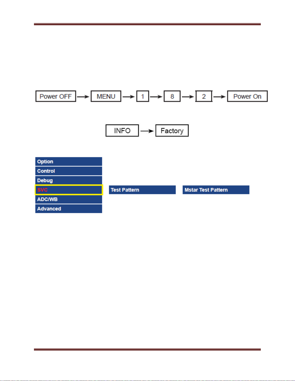
1. Wejdź w tryb serwisowy SVCInternal pattern
2. Wejdź w Tryb Serwisowy
Jeśli nie posiadasz specjalnego pilota fabrycznego
Jeśli posiadasz pilota fabrycznego
3. Wybierz SVCTest pattern
4. Sprawdź obrazy testowe
4. Rozwiązywanie problemów
4.3
4.2. Identyfikacja usterek
4.2.1. Brak zasilania
Objawy:
Wskaźniki LED na przednim panelu nie działają po podłączeniu kabla zasilającego
Przekazywanie zasilania nie działa po podłączeniu przewodu zasilającego
Urządzenie wydaje się być martwe
Główne punkty do sprawdzenia:
Przekazywanie zasilania lub diody LED na przednim panelu nie działają po podłączeniu kabla
zasilającego z powodu niepoprawnego podłączenie przewodów lub usterki płyty głównej/modułu
zasilacza, należy sprawdzić:
Sprawdź połączenie przewodów wewnątrz urządzenia
Sprawdź bezpieczniki w każdym module
Sprawdź napięcie wyjściowe z modułu zasilacza
Wymień płytę główną
Diagnostyka:
Czy dioda zasilania świeci się?
Sprawdź czy podświetlenia włącza się
kiedy 20-pinowy przewód jest
odłączony
Sprawdź napięcie w stanie
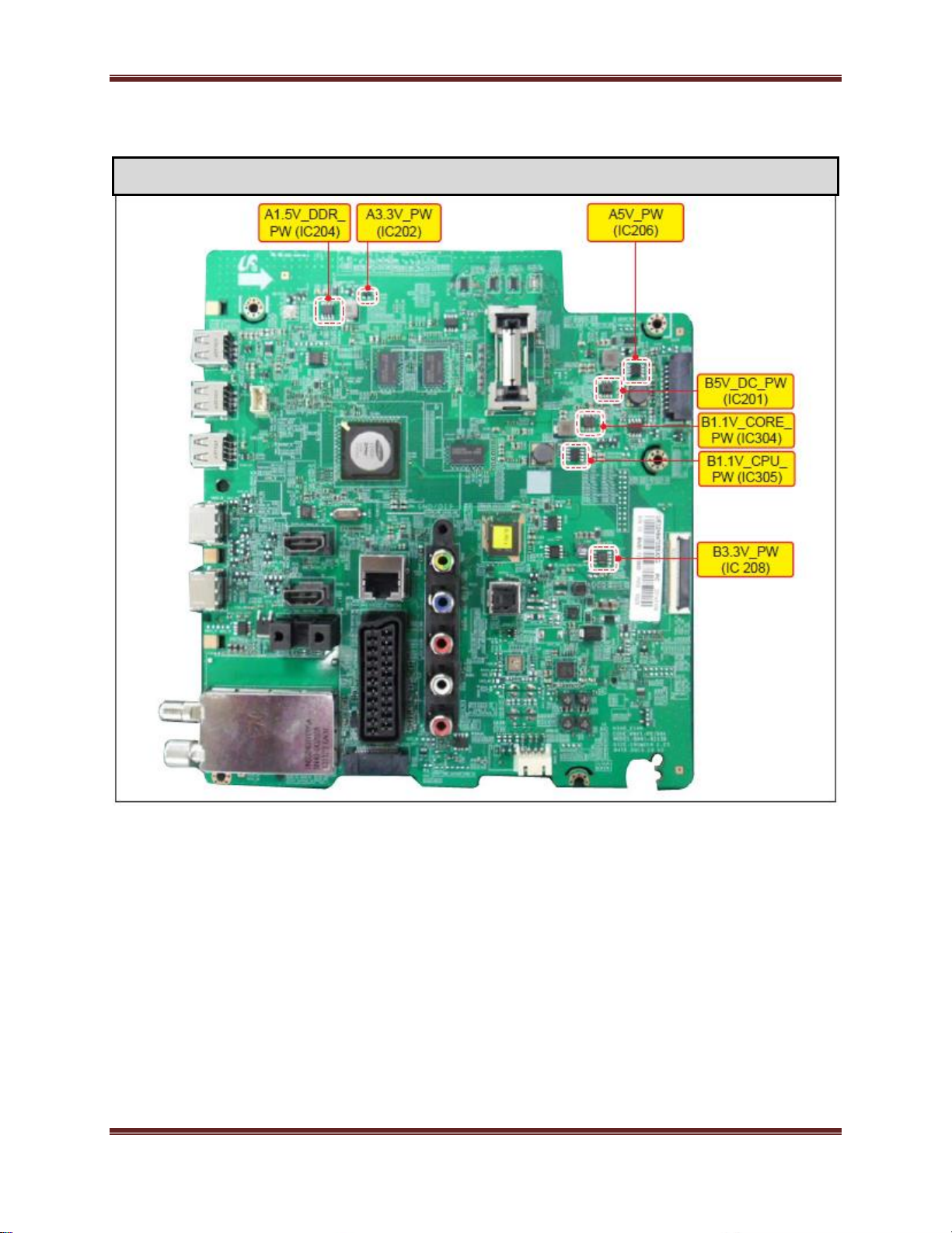
oczekiwania (BD207: A5.3V)
Sprawdź zasilanie Płyty Głównej?
BD201 / BD206: B12VS
BD209 / BD214: B13V
BD208 / BD213: B5V
Sprawdź napięcie wychodzące z
Płyty Głownej:
IC202: A3.3V
L202: B1.15V / BD211: B5V
L203: B3.3V / BD211: B1.5V
Sprawdź 20-pinowy przewód.
Sprawdź główny zespół
zasilający(Main Power Assy).
Wymień Płytę Główną
NIE
NIE
NIE
TAK
TAK
TAK
TAK
TAK
Sprawdź złącze zasilania
NIE
NIE
4. Rozwiązywanie problemów
4.4
Ostrożnie: Odłącz zasilanie przed rozpoczęciem pracy z zasilaczem
Sprawdź zasilanie modułu T-CON:
BD1(T CON): Panel_12V
B1.1V(T CON-TP): FT1_1.1V_PW
Skontaktuj się ze wsparciem
technicznym
Wymień moduł T-CON
Podłącz ponownie lub wymień
przewód LVDS
Sprawdź napięcie trafiające do
modułu T-CON:
F1(T-CON): B13V
NIE
NIE
TAK
TAK
TAK
4. Rozwiązywanie problemów
4.5
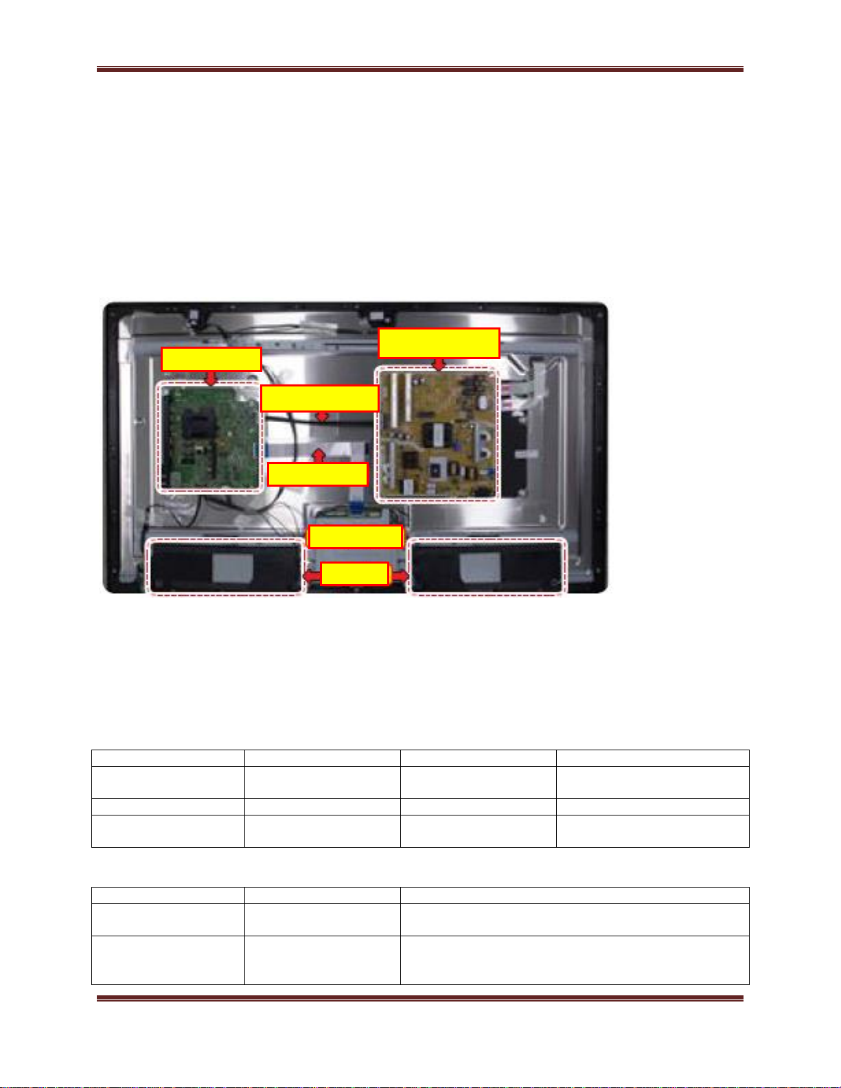
Rozmieszczenie elementów na płycie głównej
Przód Płyty Głównej
Loading...