


TFT-LCD TV
Chassis GTU37SEN
GTU40SEN
GTU46SEN
GTU52SEN
Model LE37M87BDX LE40M87BDX LE46M87BDX LE52M87BDX
SERVICE Manual
|
|
|
TFT-LCD TV |
Fashion Feature |
-Luxurious Slim Design
-Supreme Picture Quality
-Supreme Sound Quality
-Supreme Convenience Quality
-Convenience for Users
Downloaded from www.Manualslib.com manuals search engine

Copyright
©2007 by Samsung Electronics Co., Ltd. All rights reserved.
This manual may not, in whole or in part, be copied, photocopied, reproduced, translated, or converted to any electronic or machine readable form without prior written permission of Samsung Electronics Co., Ltd.
LE37M87BDX / LE40M87BDX / LE46M87BDX / LE52M87BDX Service Manual
First edition June 2007.
Printed in Korea.
Trademarks
Samsung is the registered trademark of Samsung Electronics Co., Ltd.
LE37M87BDX / LE40M87BDX / LE46M87BDX / LE52M87BDX and MacMaster Cable Adapter are trademarks of Samsung Electronics Co., Ltd.
Macintosh, Power Macintosh are trademarks of Apple Computer, Inc.
All other trademarks are the property of their respective owners.
ii
Downloaded from www.Manualslib.com manuals search engine

Contents
1.Precautions………………………………………………………………………………………………………………………………………1-1 1-1 Safety Precautions ……………………………………………………………………………………………………………………… 1-1 1-2 Servicing Precautions …………………………………………………………………………………………………………………… 1-2 1-3 Static Electricity Precautions …………………………………………………………………………………………………………… 1-2 1-4 Installation Precautions ………………………………………………………………………………………………………………… 1-3
2. Product specifications …………………………………………………………………………………………………………………………2-1
2-1 Fashion Feature…………………………………………………………………………………………………………………………… 2-1
2-2 LE37M86BDX Specifications …………………………………………………………………………………………………………… 2-2
2-3 LE40M86BDX Specifications …………………………………………………………………………………………………………… 2-2
2-4 LE46M86BDX Specifications …………………………………………………………………………………………………………… 2-2
2-5 LE52M86BDX Specifications …………………………………………………………………………………………………………… 2-2
2-6 Spec Comparison ………………………………………………………………………………………………………………………… 2-4
2-7 Option Specification ……………………………………………………………………………………………………………………… 2-5
3. Alignments and Adjustments …………………………………………………………………………………………………………………3-1
3-1 Service Instruction………………………………………………………………………………………………………………………… 3-1 3-2 How to Access Service Mode …………………………………………………………………………………………………………… 3-2 3-3 Factory Data ……………………………………………………………………………………………………………………………… 3-3 3-4 Service Adjustment ……………………………………………………………………………………………………………………… 3-7 3-5 White Ratio (Balance) Adjustment ……………………………………………………………………………………………………… 3-9 3-6 Servicing Information …………………………………………………………………………………………………………………… 3-10
4. Trouble shooting ………………………………………………………………………………………………………………………………4-1 4-1 First Checklist for Troubleshooting ……………………………………………………………………………………………………… 4-1 4-2 Checkpoints by Error Mode ……………………………………………………………………………………………………………… 4-2
5. Exploded View and Parts List ………………………………………………………………………………………………………………5-1 5-1 LE37M87BDX Exploded View…………………………………………………………………………………………………………… 5-1 5-2 LE37M87BDX Parts List ………………………………………………………………………………………………………………… 5-2 5-3 LE40M87BDX Exploded View…………………………………………………………………………………………………………… 5-3 5-4 LE40M87BDX Parts List ………………………………………………………………………………………………………………… 5-4 5-5 LE46M86BDX Exploded View…………………………………………………………………………………………………………… 5-5 5-6 LE46M86BDX Parts List ………………………………………………………………………………………………………………… 5-6 5-7 LE52M86BDX Exploded View…………………………………………………………………………………………………………… 5-7 5-8 LE52M86BDX Parts List ………………………………………………………………………………………………………………… 5-8
Downloaded from www.Manualslib.com manuals search engine

Contents
6.Electrical Parts List ……………………………………………………………………………………………………………………………6-1 6-1 LE37M87BDX Parts List …………………………………………………………………………………………………………………6-1 6-2 LE40M87BDX Parts List …………………………………………………………………………………………………………………6-33 6-3 LE46M86BDX Parts List …………………………………………………………………………………………………………………6-57 6-4 LE52M86BDX Parts List …………………………………………………………………………………………………………………6-82
7. Block Diagram …………………………………………………………………………………………………………………………………7-1
8.Wiring Diagram …………………………………………………………………………………………………………………………………8-1 8-1 Wiring Diagram …………………………………………………………………………………………………………………………… 8-1 8-2 Main Board Layout ……………………………………………………………………………………………………………………… 8-2 8-3 PIN characteristic ………………………………………………………………………………………………………………………… 5-3 8-4 Power Board Layout ……………………………………………………………………………………………………………………… 8-6
9. Schematic Diagrams ……………………………………………………………………………………………………………………………9-1
10.Operating Instructions and Installation………………………………………………………………………………………………………10-1 10-1 Front …………………………………………………………………………………………………………………………………… 10-1 10-2 Connection Panel ……………………………………………………………………………………………………………………… 10-2 10-3 Remote Control ………………………………………………………………………………………………………………………… 10-4 10-4 Installing the Stand …………………………………………………………………………………………………………………… 10-5 10-5 Installing the Wall Mount Kit ………………………………………………………………………………………………………… 10-5
11. Disassembly and Reassembly ………………………………………………………………………………………………………………11-1 11-1 Disassembly …………………………………………………………………………………………………………………………… 11-1 11-2 Reassembly …………………………………………………………………………………………………………………………… 11-5
12. PCB Diagram …………………………………………………………………………………………………………………………………12-1 12-1 Main PCB Layout ……………………………………………………………………………………………………………………… 12-1 12-2 IP Board Diagram ……………………………………………………………………………………………………………………… 12-2
13. Circuit Descriptions …………………………………………………………………………………………………………………………13-1
13-1 Block description ……………………………………………………………………………………………………………………… 13-1
13-2 Main Block ……………………………………………………………………………………………………………………………… 13-3
13-3 IP BOARD ……………………………………………………………………………………………………………………………… 13-4
14. Reference Infomation ……………………………………………………………………………………………………………………… 14-1
14-1 Technical Terms ……………………………………………………………………………………………………………………… 14-1
14-2 Pin Assignments ……………………………………………………………………………………………………………………… 14-4
14-3 Timing Chart …………………………………………………………………………………………………………………………… 14-7
14-4 Panel Description …………………………………………………………………………………………………………………… 14-11
Downloaded from www.Manualslib.com manuals search engine

-This Service Manual is a property of Samsung Electronics Co., Ltd.
Any unauthorized use of Manual can be punished under applicable International and/or domestic law.
Samsung Electronics Co.,Ltd.
416, Maetan-3Dong, Yeongtong-Gu, Suwon City, Gyeonggi-Do, Korea, 443-742
Printed in Korea
P/N : BN82-00191A-00
URL : http://itself.sec.samsung.co.kr/
Downloaded from www.Manualslib.com manuals search engine

3 Alignments and Adjustments
3 Alignments and Adjustments
3-1 Service Instruction
1.Usually, a color TV-VCR needs only slight touch-up adjustment upon installation. Check the basic characteristics such as height, horizontal and vertical sync.
2.Use the specified test equipment or its equivalent.
3.Correct impedance matching is essential.
4.Avoid overload. Excessive signal from a sweep generator might overload the front-end of the TV. When inserting signal markers, do not allow the marker generator to distort test result.
5.Connect the TV only to an AC power source with voltage and frequency as specified on the backcover nameplate.
6.Do not attempt to connect or disconnect any wire while the TV is turned on. Make sure that the power cord is disconnected before replacing any parts.
7.To protect aganist shock hazard, use an isolation transform.
3-1
Downloaded from www.Manualslib.com manuals search engine
3 Alignments and Adjustments
3-2 How to Access Service Mode
3-2-1 Entering Factory Mode
1.To enter "Service Mode" Press the remote -control keys in this sequence : - If you do not have Factory remote - control
Power OFF |
|
|
|
MUTE |
|
|
|
MENU |
|
|
|
MUTE |
|
|
|
Power On |
|
|
|
|
|
||||||||||||
|
|
|
|
|
|
|
|
|
|
|
|
|
|
|
|
|
- If you have Factory remote - control
PICTURE ON 

 DISPLAY

 FACTORY
-The buttons are active in the service mode.
1.Remote - Control Key : Power, Arrow Up, Arrow Down, Arrow Left
Arrow Right, Menu, Enter, Number Key(0~9) 2. Function - Control Key : Power, CH +, CH -, VOL +, VOL -,
Menu, TV/VIDEO(Enter)
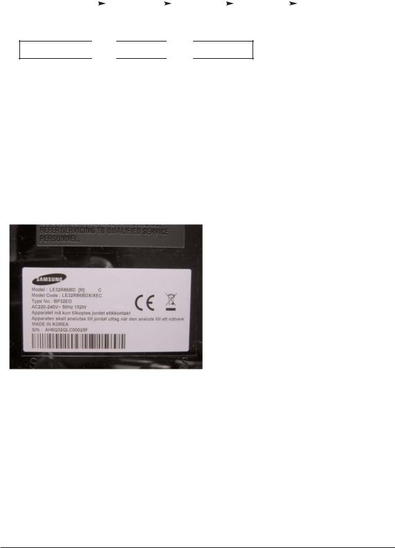
3-2-2 Panel Check
You have to check Panel Maker Because of different adjustments as follows. First of all, Check the label rating!
1) Label Rating File
- LCD PANEL MARK - |
|
A:ACER(AUO) S : SEC C : CMO |
* If not printed you could consider S(sec) panel mark. |
2) If Panel Mark is "A", Set the factory mode indicating as follows. * Option Byte
1.Inch Option 32"
2.Gamma 32"AUO
3.Panel Option AUO
Others are same shown below.
3-2
Downloaded from www.Manualslib.com manuals search engine

3 Alignments and Adjustments
3-3 Factory Data
1.Calibration
2.Service
3.White Balance
4.SVP-UX
5.Option Block
6.SGTV5810/NTP3000
7.YC Delay
8.Option Table
9.I2C Check
10.W/B MOVIE
11.Checksum
12.Reset
13.Spread Spectrum
T-BDPMPEUD-xxxx (Main Micom Ver)
T-BDPMPEUS-xxxx
BORD2_CALLA_TR-xxxx (Sub Micom Ver)
Month / Day / Year / Hour / Min. / Sec.
1.Calibration
1)AV Calibration
2)COMP Calibration
3)PC Calibration
4)HDMI Calibration
2. Option Table |
XXXX XXXX |
|
||||||
|
|
|
|
|
|
|
|
|
|
No |
|
|
Item |
|
|
Range |
|
|
|
|
|
|
|
|
|
|
1 |
|
|
Ready |
|
|
ON/OFF |
OFF |
|
2 |
|
|
Inch Option |
|
|
23"/ 26" / 32"... |
32" |
|
|
|
|
|
|
|
|
|
|
3 |
|
|
Panel Vender |
|
|
AUO/CMO... |
AMLCDINT |
|
|
|
|
|
|
|
|
|
|
4 |
|
|
Gamma |
|
|
ON/OFF |
OFF |
|
5 |
|
|
Panel Type |
|
|
Normal1/Normal2... |
Normal1 |
|
6 |
|
|
Model Option |
|
|
Calla/Lily/Bord Plus/Jasmine |
Bord Plus |
|
7 |
|
|
Tuner |
|
|
SEMCO/ALPS |
SEMCO |
|
8 |
|
|
Tuner TOP |
|
|
0~31 |
8 |
|
9 |
|
|
Auto Power |
|
|
ON/OFF |
ON |
|
10 |
|
|
Nordic |
|
|
ON/OFF |
OFF |
|
|
|
|
|
|
|
|
|
|
11 |
|
|
LNA Menu |
|
|
ON/OFF |
ON |
|
12 |
|
|
TTX On/Off |
|
|
ON/OFF |
ON |
|
|
|
|
|
|
|
|
|
|
13 |
|
|
TTX List |
|
|
Flof/List |
Flof |
|
14 |
|
|
Carrier Mute |
|
|
ON/OFF |
OFF |
|
|
|
|
|
|
|
|
|
|
15 |
|
|
High Deviation |
|
|
ON/OFF |
OFF |
|
|
|
|
|
|
|
|
|
|
16 |
|
|
VOL.Curve |
|
|
Small/Large |
Small |
|
17 |
|
|
HDMI Hotplug |
|
|
1/0 |
1 |
|
|
|
|
|
|
|
|
|
|
18 |
|
|
HDMI Clock CtrI |
|
|
1/0 |
1 |
|
|
|
|
|
|
|
|
|
|
19 |
|
|
HDMI Hotplug Dly |
3~50 |
9 |
|||
|
|
|
|
|
|
|
|
|
3-3
Downloaded from www.Manualslib.com manuals search engine

3 Alignments and Adjustments
|
|
|
|
|
|
Range |
|
|
No |
|
|
Item |
|
||
|
|
|
|
|
|
|
|
20 |
|
|
Hotel Option |
|
|
||
|
|
|
|
Hotel Mode |
ON/OFF |
OFF |
|
|
|
|
|
|
|
|
|
|
|
|
|
Power On Channel |
1~99 |
1 |
|
|
|
|
|
|
|
|
|
|
|
|
|
Power On Volume |
1~100 |
10 |
|
|
|
|
|
|
|
|
|
|
|
|
|
Max Volume |
1~100 |
100 |
|
|
|
|
|
|
|
|
|
|
|
|
|
Local Key Lock |
ON/OFF |
OFF |
|
|
|
|
|
Power On Source |
RF/Ext.1... |
RF |
|
21 |
|
|
Shop Mode |
ON/OFF |
OFF |
||
22 |
|
|
Color Space |
ON/OFF |
ON |
||
|
|
|
|
|
|
|
|
23 |
|
|
PC Ident |
ON/OFF |
OFF |
||
|
|
|
|
|
|
|
|
24 |
|
|
Language |
English/German... |
English |
||
25 |
|
|
ANYNET+ |
ON/OFF |
ON |
||
|
|
|
|
|
|
|
|
26 |
|
|
Ch.Table |
SUWON/SESK/SEH/TTSEC |
SUWON |
||
27 |
|
|
TTX Group |
Auto/West Europe... |
Auto |
||
|
|
|
|
|
|
|
|
28 |
|
|
iDTV_Cntry |
UK/France... |
UK |
||
|
|
|
|
|
|
|
|
3. White Balance
|
|
|
|
|
|
|
|
|
|
|
|
|
|
|
|
HDMI |
|
|
|
|
Item |
|
|
Range |
|
|
TV/AV/Scart |
Comp/iDTV |
PC |
||||
|
No |
|||||||||||||||
|
|
|
|
|
|
|
|
|
|
|
|
|
|
|
|
|
|
|
|
|
|
|
|
|
|
|
|
|
|
|
|
|
|
|
|
|
|
|
|
|
|
|
|
|
|
|
|
|
|
|
1 |
|
|
Sub-Briteness |
|
00H~FFH |
128 |
128 |
128 |
|
128 |
||||||
|
|
|
|
|
|
|
|
|
|
|
||||||
2 |
|
|
R-offset |
|
00H~FFH |
128 |
128 |
128 |
|
128 |
||||||
|
|
|
|
|
|
|
|
|
|
|
||||||
3 |
|
|
G-offset |
|
00H~FFH |
128 |
128 |
128 |
|
128 |
||||||
|
|
|
|
|
|
|
|
|
|
|
||||||
4 |
|
|
B-offset |
|
00H~FFH |
128 |
128 |
128 |
|
128 |
||||||
|
|
|
|
|
|
|
|
|
|
|
||||||
5 |
|
|
Sub-Contrast |
|
00H~FFH |
128 |
128 |
128 |
|
128 |
||||||
|
|
|
|
|
|
|
|
|
|
|
||||||
6 |
|
|
R-Gain |
|
00H~FFH |
128 |
128 |
128 |
|
128 |
||||||
|
|
|
|
|
|
|
|
|
|
|
||||||
7 |
|
|
G-Gain |
|
00H~FFH |
128 |
128 |
128 |
|
128 |
||||||
|
|
|
|
|
|
|
|
|
|
|
||||||
8 |
|
|
B-Gain |
|
00H~FFH |
128 |
128 |
128 |
|
128 |
||||||
4. SVP-PX
1) ComB Filter
No |
Item |
Range |
|
|
|
1 |
Y-Filter |
00H~FFH |
2) Sharpness
No |
Item |
Range |
RF |
AV |
Comp480i |
Comp480p |
Comp720p |
Comp1080i |
HDMI |
PC |
iDTV |
|
|
|
|
|
|
|
|
|
|
|
|
1 |
H2Gain |
00 ~ 1FH |
05H |
05H |
05H |
05H |
04H |
04H |
0AH |
05H |
05H |
2 |
H4Gain |
00 ~ 1FH |
04H |
0AH |
05H |
05H |
02H |
02H |
0AH |
05H |
05H |
|
|
|
|
|
|
|
|
|
|
|
|
3 |
V2Gain |
00 ~ 1FH |
0CH |
0CH |
0AH |
0CH |
0AH |
0AH |
10H |
0AH |
0AH |
|
|
|
|
|
|
|
|
|
|
|
|
4 |
V4Gain |
00 ~ 1FH |
0CH |
10H |
0CH |
0CH |
0AH |
0AH |
10H |
0AH |
0AH |
|
|
|
|
|
|
|
|
|
|
|
|
5 |
Sr2Gain |
00 ~ 1FH |
00H |
00H |
00H |
00H |
00H |
00H |
00H |
00H |
00H |
|
|
|
|
|
|
|
|
|
|
|
|
6 |
Sr4Gain |
00 ~ 1FH |
00H |
02H |
00H |
00H |
02H |
02H |
04H |
02H |
02H |
|
|
|
|
|
|
|
|
|
|
|
|
7 |
Sl2Gain |
00 ~ 1FH |
00H |
00H |
00H |
00H |
00H |
00H |
00H |
00H |
00H |
|
|
|
|
|
|
|
|
|
|
|
|
8 |
Sl4Gain |
00 ~ 1FH |
00H |
02H |
00H |
00H |
02H |
02H |
04H |
02H |
02H |
9 |
Peakth1 |
00H~FFH |
06H |
02H |
03H |
03H |
03H |
03H |
03H |
08H |
04H |
10 |
Peakth2 |
00H~FFH |
2FH |
2FH |
2FH |
2FH |
2FH |
2FH |
2FH |
2FH |
2FH |
11 |
Peskth3 |
00H~FFH |
3FH |
3FH |
3FH |
3FH |
3FH |
3FH |
3FH |
3FH |
3FH |
|
|
|
|
|
|
|
|
|
|
|
|
3-4
Downloaded from www.Manualslib.com manuals search engine

3 Alignments and Adjustments
3) NR
No |
Item |
Range |
|
|
|
|
|
1 |
Y_NR_OFF |
00H~FFH(Y_NR_OFF) |
00H |
|
|
|
|
2 |
C_NR_OFF |
00H~FFH(C_NR_OFF) |
00H |
|
|
|
|
3 |
Y_NR_ON |
00H~FFH(Y_NR_ON) |
00H |
|
|
|
|
4 |
C_NR_ON |
00H~FFH(C_NR_ON) |
00H |
|
|
|
|
4) RGB Calibration
|
No |
|
|
|
|
|
|
|
|
|
|
|
|
|
PC |
HDMI |
|
|
|
Item |
|
|
Range |
|
|
TV/AV/S_Video |
Component |
||||||
|
|
|
|
|
|
|
|
|
|
|
|
|
|
|
|
|
|
|
|
|
|
|
|
|
|
|
|
|
|
|
|
|
|
1 |
|
|
R-Offset |
|
00H~FFH |
|
3AH |
|
40H |
32H |
82H |
|||||
|
|
|
|
|
|
|
|
|
|
|
|
|||||
2 |
|
|
G-Offset |
|
00H~FFH |
|
3AH |
|
40H |
32H |
82H |
|||||
3 |
|
|
B-Offset |
|
00H~FFH |
|
3AH |
|
40H |
32H |
82H |
|||||
4 |
|
|
R-Gain |
|
00H~FFH |
|
A6H |
|
92H |
A9H |
6CH |
|||||
5 |
|
|
G-Gain |
|
00H~FFH |
|
A6H |
|
92H |
A9H |
6CH |
|||||
6 |
|
|
B-Gan |
|
00H~FFH |
|
A6H |
|
92H |
A9H |
6CH |
|||||
|
|
|
|
|
|
|
|
|
|
|
|
|
|
|
|
|
5) ADC Calibration
|
No |
|
|
|
|
|
|
|
|
|
|
|
|
|
PC |
HDMI |
|
|
|
Item |
|
|
Range |
|
|
TV/AV/S_Video |
Component |
||||||
|
|
|
|
|
|
|
|
|
|
|
|
|
|
|
|
|
|
|
|
|
|
|
|
|
|
|
|
|
|
|
|
|
|
1 |
|
|
TCD3 Contrast |
|
00H~FFH |
|
79H |
|
78H |
78H |
78H |
|||||
|
|
|
|
|
|
|
|
|
|
|
|
|||||
2 |
|
|
TCD3 Brightness |
|
00H~FFH |
|
29H |
|
20H |
20H |
20H |
|||||
3 |
|
|
TCD3 CR |
|
00H~FFH |
|
80H |
|
80H |
80H |
80H |
|||||
4 |
|
|
TCD3 CB |
|
00H~FFH |
|
80H |
|
80H |
80H |
80H |
|||||
5 |
|
|
TCD3 Delay |
|
00H~FFH |
|
00H |
|
00H |
00H |
00H |
|||||
6 |
|
|
Analog Y Offset |
|
00H~FFH |
|
40H |
|
3DH |
44H |
40H |
|||||
|
|
|
|
|
|
|
|
|
|
|
|
|||||
7 |
|
|
Analog PB Offset |
|
00H~FFH |
|
80H |
|
80H |
44H |
80H |
|||||
8 |
|
|
Analog PR Offset |
|
00H~FFH |
|
80H |
|
80H |
44H |
80H |
|||||
9 |
|
|
Analog Y Gain |
|
00H~FFH |
|
D6H |
|
B3H |
A4H |
80H |
|||||
10 |
|
|
Analog PB Gain |
|
00H~FFH |
|
80H |
|
B3H |
ACH |
80H |
|||||
|
|
|
|
|
|
|
|
|
|
|
|
|||||
11 |
|
|
Analog PR Gain |
|
00H~FFH |
|
80H |
|
B3H |
A7H |
80H |
|||||
12 |
|
|
Black Level |
|
00H~FFH |
|
00H |
|
00H |
00H |
00H |
|||||
13 |
|
|
Svp Brightness |
|
00H~FFH |
|
00H |
|
00H |
00H |
00H |
|||||
6) Caliration Target
|
No |
|
|
|
|
|
|
|
|
|
|
|
|
|
|
|
|
|
|
|
Item |
|
|
Range |
|
|
low |
high |
Delta |
||||||
|
|
|
|
|
|
|
|
|
|
|
|
|
|
|
|
|
|
|
|
|
|
|
|
|
|
|
|
|
|
|
|
|
|
|
|
1 |
|
|
AV ADC |
|
00H~FFH |
|
10H |
|
DCH |
|
02H |
||||||
|
|
|
|
|
|
|
|
|
|
|
|
||||||
2 |
|
|
COMP ADC |
|
00H~FFH |
|
10H |
|
EBH |
|
02H |
||||||
3 |
|
|
PC ADC |
|
00H~FFH |
|
10H |
|
DCH |
|
04H |
||||||
4 |
|
|
ALL RGB |
|
00H~FFH |
|
01H |
|
EBH |
|
0AH |
||||||
3-5
Downloaded from www.Manualslib.com manuals search engine
3 Alignments and Adjustments
7) Color Management
|
No |
|
|
|
|
|
|
|
|
|
|
|
Item |
Range |
|
||||
|
|
|
|
|
|
|
|
|
|
|
|
|
|
|
|
|
|
|
|
1 |
|
|
Skin Direction |
|
Reddish/Yellowish |
Reddish |
|||
|
|
|
|
|
|
|
|||
2 |
|
|
Skin Enhance |
|
00H~FFH |
00H |
|||
3 |
|
|
Green Stretch |
|
00H~FFH |
00H |
|||
4 |
|
|
Blue Stretch |
|
00H~FFH |
00H |
|||
5.Option Block
1)FRC(Micronas)
2)FRC2X
|
No |
|
Item |
Range |
|
|
|
|
|
|
|
1 |
|
OUTCON |
1~3 |
0 |
|
2 |
|
GAMMA |
1~7 |
0 |
|
|
|
|
|
|
|
3 |
|
OCC_MODE |
0/1 |
0 |
|
4 |
|
FALLBACK |
0/1 |
0 |
|
|
|
|
|
|
|
5 |
|
DBG_MARK |
0/1 |
0 |
|
|
|
|
|
|
|
6 |
|
SPR_CBR |
0/1 |
0 |
|
7 |
|
BIT_EXPAND |
0/1 |
0 |
|
|
|
|
|
|
|
8 |
|
INV_BIT_EXPAND |
0/1 |
0 |
|
|
|
|
|
|
|
9 |
|
REPEAT_MODE |
0/1 |
0 |
|
|
|
|
|
|
|
10 |
|
DEMO_ON_OFF |
0/1 |
0 |
|
|
|
|
|
|
|
11 |
|
MMU_RD_START |
00H~FFH |
00H |
|
|
|
|
|
|
|
12 |
|
ME_RD_START |
00H~FFH |
00H |
|
|
|
|
|
|
|
13 |
|
MC_RD_START |
00H~FFH |
00H |
|
14 |
|
CMZL(0x36E) |
00H~0FH |
0H |
|
15 |
|
BLOL(0x2A7) |
00H~0FH |
0H |
|
16 |
|
LOGO(0x2A7) |
00H~0FH |
0H |
|
|
|
|
|
|
|
3-6
Downloaded from www.Manualslib.com manuals search engine

3 Alignments and Adjustments
3) FBE2
No |
Item |
Range |
RF |
AV/ |
COMP |
COMP |
COMP |
HDMI |
DTV |
DTV |
S-VIDEO |
(480i/576i) |
(480p/576p) |
(720p/1080i/1080p) |
|||||||
|
|
|
|
|
|
|
|
|
|
|
1 |
Pattern Select |
0~20 |
0 |
0 |
0 |
0 |
0 |
0 |
0 |
0 |
2 |
BS-On |
0/1 |
1 |
1 |
1 |
1 |
1 |
1 |
1 |
1 |
|
|
|
|
|
|
|
|
|
|
|
3 |
B-Slope Gain |
0~255 |
34 |
44 |
44 |
64 |
64 |
64 |
64 |
64 |
|
|
|
|
|
|
|
|
|
|
|
4 |
B-Tilt Min |
0~255 |
20 |
20 |
20 |
20 |
20 |
20 |
20 |
20 |
|
|
|
|
|
|
|
|
|
|
|
5 |
B-Tilt Max |
0~255 |
120 |
120 |
120 |
120 |
120 |
120 |
120 |
120 |
|
|
|
|
|
|
|
|
|
|
|
6 |
B-Tilt Slope |
0~255 |
128 |
128 |
128 |
128 |
128 |
128 |
128 |
128 |
|
|
|
|
|
|
|
|
|
|
|
7 |
LFunc-Basis |
0~255 |
30 |
20 |
20 |
40 |
70 |
55 |
75 |
75 |
|
|
|
|
|
|
|
|
|
|
|
8 |
Hfunc-Basis |
0~255 |
30 |
40 |
40 |
40 |
75 |
65 |
88 |
88 |
9 |
Mean-Offset1 |
0~255 |
20 |
100 |
100 |
75 |
75 |
75 |
75 |
75 |
10 |
Mean Offset2 |
0~255 |
120 |
200 |
200 |
155 |
225 |
225 |
225 |
225 |
11 |
Mean Slope |
0~255 |
56 |
56 |
56 |
45 |
85 |
85 |
85 |
85 |
|
|
|
|
|
|
|
|
|
|
|
12 |
Input Offset |
0~255 |
128 |
128 |
128 |
128 |
128 |
128 |
128 |
128 |
|
|
|
|
|
|
|
|
|
|
|
13 |
Input Gain |
0~255 |
128 |
128 |
128 |
128 |
128 |
128 |
128 |
128 |
|
|
|
|
|
|
|
|
|
|
|
14 |
ACR Offset |
0~128 |
15 |
15 |
15 |
15 |
15 |
15 |
15 |
15 |
|
|
|
|
|
|
|
|
|
|
|
15 |
ACR Th1 |
0~255 |
30 |
30 |
30 |
30 |
30 |
30 |
30 |
30 |
|
|
|
|
|
|
|
|
|
|
|
16 |
ARC Th2 |
0~255 |
130 |
130 |
130 |
130 |
130 |
130 |
130 |
130 |
17 |
Skin Enable |
0/1 |
1 |
1 |
1 |
1 |
1 |
1 |
1 |
1 |
18 |
Skin Tu |
0~255 |
165 |
165 |
165 |
150 |
165 |
165 |
128 |
128 |
|
|
|
|
|
|
|
|
|
|
|
19 |
Skin Tv |
0~255 |
140 |
140 |
140 |
140 |
128 |
128 |
128 |
128 |
20 |
M Skin Tu |
0~255 |
128 |
128 |
128 |
128 |
128 |
128 |
128 |
128 |
|
|
|
|
|
|
|
|
|
|
|
21 |
M Skin TV |
0~255 |
128 |
128 |
128 |
128 |
128 |
128 |
128 |
128 |
22 |
Sub Color |
0~255 |
115 |
128 |
128 |
135 |
140 |
150 |
143 |
143 |
23 |
M-Au-Sub Color |
0~255 |
128 |
128 |
128 |
128 |
128 |
128 |
128 |
128 |
24 |
M-Wi-Sub Color |
0~255 |
128 |
128 |
128 |
128 |
128 |
128 |
128 |
128 |
|
|
|
|
|
|
|
|
|
|
|
25 |
MW-Skin-Tu |
0~255 |
128 |
128 |
128 |
128 |
128 |
128 |
128 |
128 |
26 |
MW-Skin-Tv |
0~255 |
128 |
128 |
128 |
128 |
128 |
128 |
128 |
128 |
|
|
|
|
|
|
|
|
|
|
|
3-7
Downloaded from www.Manualslib.com manuals search engine

3 Alignments and Adjustments
4) Pdp Logic
|
|
|
Item |
Range |
|
|
No |
|
|||
|
|
|
|
|
|
1 |
|
Pattern Srlect |
0~63 |
0 |
|
2 |
|
Data updata |
ON/OFF |
OFF |
|
3 |
|
Data Type |
42"EU MRT/42"EU MESH/....... |
42"EU MRT |
|
4 |
|
CDC Sw |
ON/OFF |
OFF |
|
5 |
|
CDC Strengh Th |
0~31 |
0 |
|
6 |
|
BRE Sw |
ON/OFF |
OFF |
|
|
|
|
|
|
|
7 |
|
FRC Repeat Mode |
ON/OFF |
OFF |
|
8 |
|
FRC CBG Mark On |
0~15 |
0 |
|
9 |
|
ERC Bypass |
ON/OFF |
OFF |
|
|
|
|
|
|
|
10 |
|
Panel Type |
- |
0H |
|
|
|
|
|
|
|
11 |
|
Panel Inch |
- |
SD |
|
|
|
|
|
|
|
12 |
|
Panel Version |
- |
|
|
|
|
|
|
|
|
13 |
|
Logic Sw Version |
- |
0H 0H 0H |
|
6. SGTV5810/NTP3000
|
No |
|
Item |
Range |
|
|
|
|
|
|
|
1 |
|
ID Tone Shift |
1H~FH |
01H |
|
2 |
|
ID Tone Thresh |
00H~FFH |
7FH |
|
3 |
|
Demod Prescaler |
00H~20H |
13H |
|
4 |
|
Master Volume |
00H~30H |
13H |
|
5 |
|
PWM Modulation |
80H~F2H |
F1H |
|
6 |
|
DRC Threshold |
00H~7FH |
06H |
|
|
|
|
|
|
|
7 |
|
Speaker EQ |
ON/OFF |
OFF |
|
|
|
|
|
|
|
7. YC Delay
|
No |
|
Item |
Range |
|
|
|
|
|
|
|
1 |
|
RF PAL-B/G |
00H~FFH |
AAH |
|
2 |
|
RF PAL - D/K |
00H~FFH |
99H |
|
3 |
|
RF PAL - I |
00H~FFH |
99H |
|
4 |
|
RF SECAM - B/G |
00H~FFH |
88H |
|
5 |
|
RF SECAM - D/K |
00H~FFH |
44H |
|
6 |
|
RF SECAM -L/L' |
00H~FFH |
88H |
|
|
|
|
|
|
|
7 |
|
RF NTSC 3.58 |
00H~FFH |
44H |
|
|
|
|
|
|
|
8 |
|
RF NTSC 4.43 |
00H~FFH |
CCH |
|
9 |
|
AV PAL |
00H~FFH |
AAH |
|
10 |
|
AV SECAM |
00H~FFH |
88H |
|
11 |
|
AV NTSC 3.58 |
00H~FFH |
30H |
|
|
|
|
|
|
|
12 |
|
AV NTSC 4.43 |
00H~FFH |
AAH |
|
13 |
|
AV PAL60 |
00H~FFH |
77H |
|
|
|
|
|
|
|
3-8
Downloaded from www.Manualslib.com manuals search engine

3 Alignments and Adjustments
8. Adjust
|
No |
|
Item |
Range |
|
|
|
|
|
|
|
1 |
|
Video Mute Time |
0~255 |
10 |
|
2 |
|
Dynamic Contrast |
ON/OFF |
OFF |
|
3 |
|
Dynamic Dimming |
ON/OFF |
ON |
|
4 |
|
Dynamic CE |
ON/OFF |
OFF |
|
5 |
|
LNA PLUS |
|
|
|
|
|
|
RFDB-1 Level |
0~255 |
2 |
|
|
|
|
|
|
|
|
|
RFDB-2 Level |
0~255 |
5 |
|
|
|
|
|
|
|
|
|
RFDB-3 Level |
0~255 |
7 |
|
|
|
RFDB-4 Level |
0~255 |
24 |
6 |
|
Magazine LNA |
ON/OFF |
OFF |
|
7 |
|
PixelShift Test |
ON/OFF |
OFF |
|
|
|
|
|
|
|
8 |
|
Debug |
ON/OFF |
OFF |
|
9 |
|
ACR |
ON/OFF |
OFF |
|
10 |
|
D-Watchdog |
ON/OFF |
ON |
|
11 |
|
UART Select |
MAIN / IDTV / PDP Lvds ON / PDP Lvds OFF |
OFF |
|
|
|
|
|
|
|
9.I2C Check
10.W/B MOVIE
No |
Item |
Range |
TV/AV/S_Video |
Component |
PC |
HDMI |
Scart1/2 |
1 |
WB Movie |
ON/OFF |
OFF |
OFF |
OFF |
OFF |
OFF |
|
|
|
|
|
|
|
|
2 |
Color Mode |
Movie |
Movie |
Dynamic |
Dynamic |
Dynamic |
Dynamic |
|
|
|
|
|
|
|
|
3 |
Color Tone |
|
Cool1 |
Cool1 |
Cool1 |
Cool1 |
Cool1 |
4 |
Msub Brigh |
0~255 |
128 |
128 |
128 |
128 |
128 |
|
|
|
|
|
|
|
|
5 |
Msub Contr |
0~255 |
128 |
128 |
128 |
128 |
128 |
6 |
W1_RGAIN |
0~255 |
157 |
161 |
144 |
161 |
157 |
7 |
W1_BGAIN |
0~255 |
76 |
74 |
117 |
76 |
76 |
|
|
|
|
|
|
|
|
8 |
W1_R_OFFS |
0~255 |
119 |
119 |
127 |
118 |
119 |
9 |
W1_B_OFFS |
0~255 |
138 |
140 |
110 |
141 |
138 |
10 |
W2_RGAIN |
0~255 |
142 |
143 |
149 |
142 |
142 |
8 |
W2_BGAIN |
0~255 |
48 |
47 |
93 |
51 |
48 |
|
|
|
|
|
|
|
|
9 |
W2_R_OFFS |
0~255 |
129 |
127 |
124 |
128 |
129 |
|
|
|
|
|
|
|
|
10 |
W2_B_OFFS |
0~255 |
143 |
145 |
110 |
143 |
143 |
11 |
NO_RGAIN |
0~255 |
141 |
139 |
137 |
141 |
141 |
12 |
NO_BGAIN |
0~255 |
104 |
102 |
123 |
104 |
104 |
13 |
NO_R_OFFS |
0~255 |
126 |
125 |
126 |
121 |
126 |
14 |
NO_B_OFFS |
0~255 |
136 |
133 |
114 |
133 |
136 |
15 |
C2_RGAIN |
0~255 |
124 |
122 |
123 |
125 |
124 |
16 |
C2_BGAIN |
0~255 |
142 |
141 |
156 |
143 |
142 |
17 |
C2_R_OFFS |
0~255 |
128 |
129 |
117 |
128 |
128 |
18 |
C2_B_OFFS |
0~255 |
128 |
127 |
116 |
128 |
128 |
19 |
Movie Contr |
0~100 |
100 |
100 |
100 |
100 |
100 |
20 |
Movie Brigh |
0~100 |
45 |
45 |
45 |
45 |
45 |
21 |
Movie Color |
0~100 |
55 |
55 |
55 |
55 |
55 |
22 |
Movie Sharp |
0~100 |
75 |
75 |
75 |
75 |
75 |
3-9
Downloaded from www.Manualslib.com manuals search engine

3 Alignments and Adjustments
11.Checksum 7A72
12.Reset
13.Spread Spectrun
|
No |
|
Item |
Range |
|
|
|
|
|
|
|
1 |
|
Spectrum |
ON/OFF |
ON |
|
2 |
|
Delta |
-128 ~ +128 |
0 |
|
3 |
|
Positive |
0~99 |
8 |
|
4 |
|
Negative |
0~99 |
2 |
|
5 |
|
Speed |
0~7 |
0 |
|
6 |
|
Time |
0~7 |
4 |
|
|
|
|
|
|
|
7 |
|
FBE Spectrum |
ON/OFF |
OFF |
|
|
|
|
|
|
|
8 |
|
FEE Delta |
0~5 |
0 |
|
3-10
Downloaded from www.Manualslib.com manuals search engine

3 Alignments and Adjustments
3-4 Service Adjustment
3-4-1 White Balance - Calibration
If picture color is wrong, do calibration first.
Equipment : CA210, Patten : chess pattern
Execute calibration in Factory Mode
Source AV : PAL composite, Component : 1280*720/60Hz
PC : 1024*768/60Hz
( chess patten )
3-4-2 White Balance - Adjustment
If picture color is wrong, check White Balance condition.
Equipment : CA210, Patten : Flat W/B Pattern
Adjust W/B in Factory Mode
Sub brightness and R/G/B Offset controls low light region
Sub contrast and R/G/B Gain controls high light region
Source AV : PAL composite, Component : 1280*720/60Hz
HDMI[DVI] : 1280*720/60Hz
[ Test Pattern : MIK K-7256 PAttern #92 ]
*Color temperature
1500K +/-500, -6 ~-20 MPCD
*Color coordinate |
|
H/L : 267/263 +/- 2 |
35.0 Ft +/- 2.0Ft |
L/L : 270/260 +/- 3 |
1.5 Ft +/- 0.2Ft |
Flat W/B Pattern |
|
3-11
Downloaded from www.Manualslib.com manuals search engine
3 Alignments and Adjustments
3-4-3 Conditions for Measurement
1.On the basis of toshiba ABL pattern : High Light level (57 IRE) - INPUT SIGNAL GENERATOR : MSPG-925LTH
* Mode |
NO |
2 |
: 744X484@60 Hz |
|
NO |
6 |
: 1280X720@60 Hz |
|
NO 21 |
: 1024X768@60 Hz |
|
* Pattern |
NO |
36 |
: 16 Color Pattern |
|
NO |
16 |
: Toshiba ABL Pattern |
2.Optical measuring device : CA210 (FL)
Please use the MSPG-925 LTH generator for model LE26M51B/LE32M51B/LE40M51B/LE46M51B.
3-4-4 Method of Adjustment
1. Adjust the white balance of AV, Component and DVI Modes.
(AV  Component)
a)Set the input to the mode in which the adjustment will be made (RF  DTV
DTV  PC
PC  DVI).
DVI).
*Input signal - VIDEO Mode : Model #2 (744*484 Mode), Pattern #16
-DTV,DVI Mode : Model #6 (1280*720 Mode), Pattern #16
-HDMI Mode: Model #6(1280*720 Mode), Pattern #16
b)Enter factory color control, confirm the data.
c)Adjust the low light. (Refer to table 1, 2 in adjustment position by mode)
-Adjust sub - Brightness to set the 'Y' value.
-Adjust red offset ('x') and blue offset ('y') to the color coordinates.
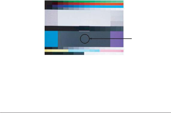
Picture 4-2 Flat W/B Pattern
Low light
Measurement point
*Do not adjust green offset data.
d)Adjust the high light. (Refer to table 1, 2 in adjustment position by mode) - Adjust red gain ('x') and blue gain ('y') to the color coordinates.
*Do not adjust the green gain and sub-contrast (Y) data.
3-12
Downloaded from www.Manualslib.com manuals search engine

3 Alignments and Adjustments
d) Adjust the high light. (Refer to table 1, 2 in adjustment position by mode) - Adjust red gain ('x') and blue gain ('y') to the color coordinates.
* Do not adjust the green gain and sub-contrast (Y) data.
Picture 4-3 Flat W/B Pattern
High light
Measurement point
3-13
Downloaded from www.Manualslib.com manuals search engine
3 Alignments and Adjustments
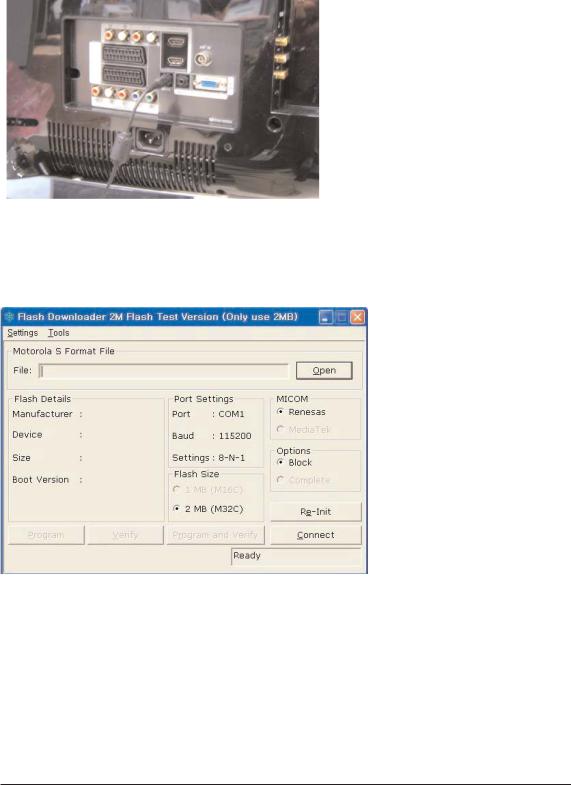
3-5 Software Upgrade
3-5-1 How to Update Flash ROM
1.Install the Flash Downloader
ConnectSet(Service Jack)and Jig Cable to execute Program Update.
2.Flash Downloader program update
-Before Turning on the set,Click "connect"which is under of OSD Screen! -Turn on the Set.
3-14
Downloaded from www.Manualslib.com manuals search engine
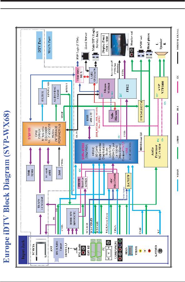
7 Block Diagrams
7 Block Diagram
- This Document can not be used without Samsung’s authorization
7-1
Downloaded from www.Manualslib.com manuals search engine
7 Block Diagrams
Memo
7-2
Downloaded from www.Manualslib.com manuals search engine
13 Circuit Descriptions
13 Circuit Descriptions
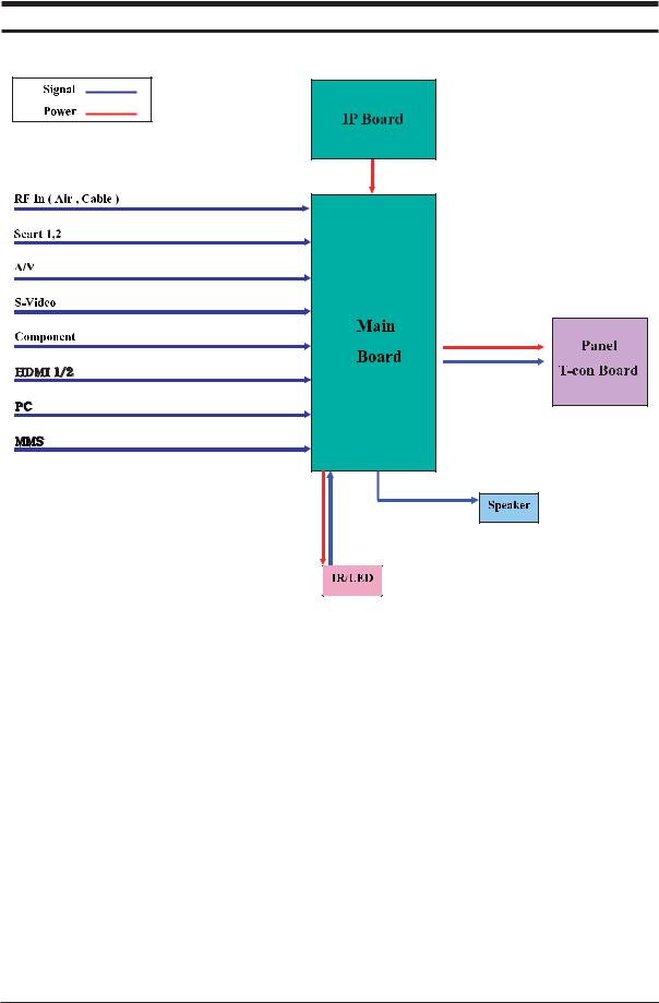
13-1 Block description
Mosel consists of three main blocks
1.Main board : Video signal processing
2.IP board : Power supply & Inverter
3.T-con board : LCD Panel control
13-1
Downloaded from www.Manualslib.com manuals search engine
13 Circuit Descriptions
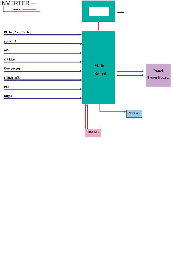
Mosel consists of three main blocks
1.Main board : Video signal processing
2.SMPS : Power supply
3.T-con board : LCD Panel control
13-2
Downloaded from www.Manualslib.com manuals search engine

13 Circuit Descriptions
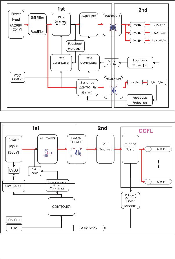
13-2 Main Block |
13-3
Downloaded from www.Manualslib.com manuals search engine
13 Circuit Descriptions
13-3 IP Board |
13-4 |
Downloaded from www.Manualslib.com manuals search engine
11 Disassembly and Reassembly
11 Disassembly and Reassembly
This section of the service manual describes the disassembly and reassembly procedures for the TFT-LCD TV.
 WARNING : This monitor contains electrostatically sensitive devices. Use caution when handling these components.
11-1 Disassembly (LE40F71BX)
 Cautions : 1. Disconnect the monitor from the power source before disassembly.
2. Follow these directions carefully; never use metal instruments to pry apart the cabinet.
Description |
Picture Description |
|
|
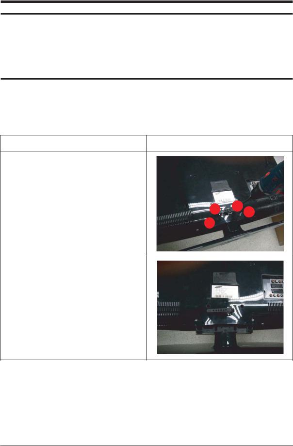
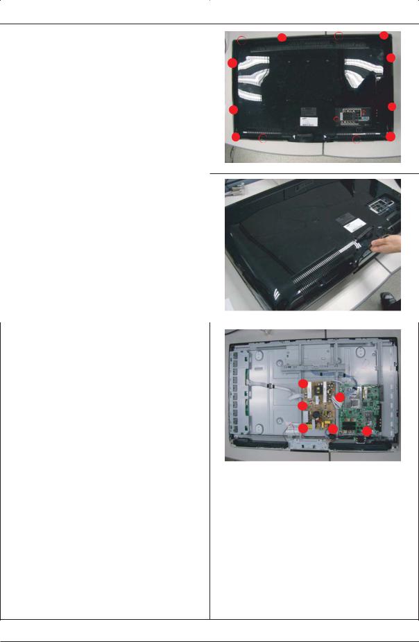
1.Place monitor face down on cushioned table. Remove screws from the Stand.
Remove stand.
11-1
Downloaded from www.Manualslib.com manuals search engine
11 Disassembly and Reassembly
Description |
Picture Description |
|
|
2. Remove screws from the rear-cover and lift up the rear-cover.
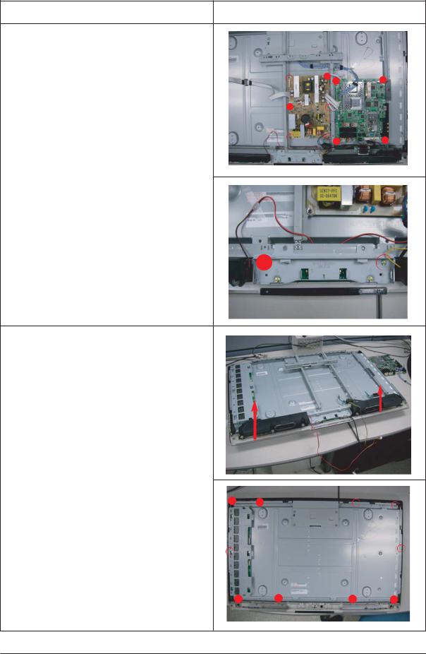
3.Disconnet cables from the main and power boards.
11-2
Downloaded from www.Manualslib.com manuals search engine
11 Disassembly and Reassembly
Description |
Picture Description |
|
|
4.Remove screws from the boards and stand BRKT.
5.Lift up the speakers.
Remove screws from the BRKT.
11-3
Downloaded from www.Manualslib.com manuals search engine
11 Disassembly and Reassembly
Description |
Picture Description |
|
|
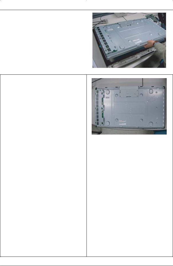
6. Lift up the Panel.
7. Remove Panel Front.
11-4
Downloaded from www.Manualslib.com manuals search engine

11 Disassembly and Reassembly
11-2 Reassembly
Reassembly procedures are in the reverse order of disassembly procedures.
11-5
Downloaded from www.Manualslib.com manuals search engine
 Loading...