


Samsung GSM40SE, GSM37SE, GSM32SE, GSM27SE, LE40S71B Service Manual
...TFT-LCD TV
Chassis GSM27SE
GSM32SE
GSM37SE
GSM40SE
Model LE27S71B
LE32S71B
LE37S71B
LE40S71B
SERVICE Manual
|
|
|
TFT-LCD TV |
Fashion Feature |
|
|
|
- Luxurious Slim Design |
|
|
- Supreme Picture Quality |
|
|
- Supreme Sound Quality |
|
|
- Supreme Convenience Quality |
|
|
- Convenience for Users |
-This Service Manual is a property of Samsung Electronics Co., Ltd.
Any unauthorized use of Manual can be punished under applicable International and/or domestic law.
Samsung Electronics Co.,Ltd.
416, Maetan-3Dong, Yeongtong-Gu, Suwon City, Gyeonggi-Do, Korea, 443-742
Printed in Korea
P/N : BN82-00139J-00
URL : http://itself.sec.samsung.co.kr/
1 Precautions
1 Precautions
Follow these safety, servicing and ESD precautions to prevent damage and to protect against potential hazards such as electrical shock.
1-1 Safety Precautions
1-1-1 Warnings
1.For continued safety, do not attempt to modify the circuit board.
2.Disconnect the AC power and DC Power Jack before servicing.
1-1-2 Servicing the LCD Monitor
1.When servicing the LCD Monitor Disconnect the AC line cord from the AC outlet.
2.It is essential that service technicians have an accurate voltage meter available at all times. Check the calibration of this meter periodically.
1-1-3 Fire and Shock Hazard
Before returning the monitor to the user, perform the following safety checks:
1.Inspect each lead dress to make certain that the leads are not pinched or that hardware is not lodged between the chassis and other metal parts in the monitor.
2.Inspect all protective devices such as nonmetallic control knobs, insulating materials, cabinet backs, adjustment and compartment covers or shields, isolation resistor-capacitor networks, mechanical insulators, etc.
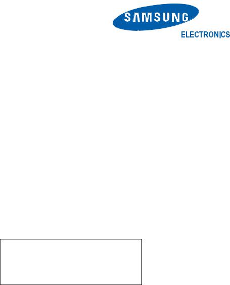
3.Leakage Current Hot Check (Figure 1-1):
WARNING: Do not use an isolation transformer during this test.
Use a leakage current tester or a metering system that complies with American National Standards Institute (ANSI C101.1, Leakage Current for Appliances), and Underwriters Laboratories (UL Publication UL1410, 59.7).
Figure 1-1. Leakage Current Test Circuit
1-1-4 Product Safety Notices
Some electrical and mechanical parts have special safety-related characteristics which are often not evident from visual inspection. The protection they give may not be obtained by replacing them with components rated for higher voltage, wattage, etc. Parts that have special safety characteristics are identified by  on schematics and parts lists. A substitute replacement that does not have the same safety characteristics as the recommended replacement part might create shock, fire and/or other hazards. Product safety is under review continuously and new instructions are issued whenever appropriate.
1-1

1 Precautions
1-2 Servicing Precautions
WARNING: |
An electrolytic capacitor installed with the wrong polarity might explode. |
Caution: |
Before servicing units covered by this service manual, read and follow the Safety |
|
Precautions section of this manual. |
Note: |
If unforeseen circumstances create conflict between the following servicing precautions and any of the safety |
|
precautions, always follow the safety precautions. |
1-2-1 General Servicing
Precautions
1.Always unplug the unit s AC power cord from the AC power source and disconnect the DC Power Jack before attempting to:
(a) remove or reinstall any component or assembly, (b) disconnect PCB plugs or connectors, (c) connect a test component in parallel with an electrolytic capacitor.
2.Some components are raised above the printed circuit board for safety. An insulation tube or tape is sometimes used. The internal wiring is sometimes clamped to prevent contact with thermally hot components. Reinstall all such elements to their original position.
3.After servicing, always check that the screws, components and wiring have been correctly reinstalled. Make sure that the area around the serviced part has not been damaged.
4.Check the insulation between the blades of the AC plug and accessible conductive parts (examples: metal panels, input terminals and earphone jacks).
5.Insulation Checking Procedure: Disconnect the power cord from the AC source and turn the power switch ON. Connect an insulation resistance meter (500 V) to the blades of the AC plug.
The insulation resistance between each blade of the AC plug and accessible conductive parts (see above) should be greater than 1 megohm.
6.Always connect a test instrument s ground lead to the instrument chassis ground before connecting the positive lead; always remove the instrument s ground lead last.
1-3 Static Electricity Precautions
Some semiconductor (solid state) devices can be easily damaged by static electricity. Such components are commonly called Electrostatically Sensitive Devices (ESD). Examples of typical ESD are integrated circuits and some field-effect transistors. The following techniques will reduce the incidence of component damage caused by static electricity.
1.Immediately before handling any semiconductor components or assemblies, drain the electrostatic charge from your body by touching a known earth ground. Alternatively, wear a discharging wrist-strap device. To avoid a shock hazard, be sure to remove the wrist strap before applying power to the monitor.
2.After removing an ESD-equipped assembly, place it on a conductive surface such as aluminum foil to prevent accumulation of an electrostatic charge.
3.Do not use freon-propelled chemicals. These can generate electrical charges sufficient to damage ESDs.
4.Use only a grounded-tip soldering iron to solder or desolder ESDs.
5.Use only an anti-static solder removal device. Some solder removal devices not classified as anti-static can generate electrical charges sufficient to damage ESDs.
6.Do not remove a replacement ESD from its protective package until you are ready to install it. Most replacement ESDs are packaged with leads that are electrically shorted together by conductive foam, aluminum foil or other conductive materials.
7.Immediately before removing the protective material from the leads of a replacement ESD, touch the protective material to the chassis or circuit assembly into which the device will be installed.
Caution: Be sure no power is applied to the chassis or circuit and observe all other safety
precautions.
8.Minimize body motions when handling unpackaged replacement ESDs. Motions such as brushing clothes together, or lifting your foot from a carpeted floor can generate enough static electricity to damage an ESD.
1-2

1 Precautions
1-4 Installation Precautions
1.For safety reasons, more than two people are required for carrying the product.
2.Keep the power cord away from any heat emitting devices, as a melted covering may cause fire or electric shock.
3.Do not place the product in areas with poor ventilation such as a bookshelf or closet. The increased internal temperature may cause fire.
4.Bend the external antenna cable when connecting it to the product. This is a measure to protect it from being exposed to moisture. Otherwise, it may cause a fire or electric shock.
5.Make sure to turn the power off and unplug the power cord from the outlet before repositioning the product. Also check the antenna cable or the external connectors if they are fully unplugged. Damage to the cord may cause fire or electric shock.
6.Keep the antenna far away from any high-voltage cables and install it firmly. Contact with the highvoltage cable or the antenna falling over may cause fire or electric shock.
7.When installing the product, leave enough space (10cm) between the product and the wall for ventilation purposes.
A rise in temperature within the product may cause fire.
1-3

1 Precautions
Memo
1-4

2 Product Specifications
2 Product specifications
2-1 Fashion Feature
Supreme Digital Interface & Networking
-With a built-in HD digital tuner, it supports HD broadcasting with no particular set-top box and provides simple access with a single remote control.
Excellent Picture Quality
-DNIe technology provides life-like clear images.
Dynamic Contrast
-Automatically detects the input visual signal and adjusts to create optimum contrast.
SRS TruSurround XT
-SRS TruSurround XT provides a virtual Dolby surround system.
Convenience
-The TV utilizes the HDMI system to implement perfect digital sound and picture quality.
2-1

2 Product Specifications
2-2 LE27S71B Specifications
Item |
|
|
Description |
|
|
||
LCD Panel |
LCDPanel:TFT-LCDPanel,RGBVerticalstripe,normalyblack,27-Inchviewable,0.1455(H)*0.4365(V)mmPixelPitch |
||
|
|
|
|
Scanning Frequency |
Horizontal : |
30 kHz ~ 61 kHz (Automatic) / Vertical : 60 Hz ~ 75 Hz (Automatic) |
|
|
|
|
|
Display Colors |
16.7M colors |
||
Maximum Resolution |
Horizontal : 1360 Pixels |
||
|
Vertical |
: 768 Pixels |
|
Input Video Signal |
Analog 0.7 Vp-p ± 5% positive at 75Ω, internally terminated |
||
|
|
|
|
Input Sync Signal |
Type : Seperate H/V |
||
|
Level : TTL level |
||
|
|
|
|
Maximum Pixel Clock rate |
80 MHz |
|
|
|
|
|
|
Active Display |
|
|
|
Horizontal/Vertical |
596.3 mm / 335.2 mm |
||
|
|
|
|
AC power voltage & Frequency |
AC 220 ~ 240 V, 60/50 Hz |
||
|
|
|
|
Power Consumption |
100 W 1W |
||
|
|
|
|
Dimensions(W x D x H) |
|
|
|
Set |
769 x 226 x 526 mm(30.27 x 8.89 x 20.70 inches) After installation Stand |
||
|
769 x 79 x 471 mm(30.27 x 3.11 x 18.54 inches) Without stand |
||
|
|
|
|
Weight |
|
|
|
Set(After installation Stand) |
10.4 kg (22.9 lbs) |
||
|
|
|
|
TV System |
Tunning |
|
Frequency Synthesize |
|
|
|
|
|
System |
|
PAL, SECEM |
|
|
|
|
|
Sound |
|
MONO, STEREO, NICAM |
|
|
|
|
Environmental Considerations |
Operating Temperature : 50°F ~ 104°F (10°C ~ 40°C) |
||
|
Operating Humidity : 10 % ~ 80 % |
||
|
Storage Temperature : -4°F ~ 113°F (-20°C ~ 45°C) |
||
|
Storage Humidity : 5 % ~ 95 % |
||
|
|
|
|
Antena Input |
75Ω |
|
|
|
|
|
|
|
-MAX Internal speaker Out : Right : 5W / Left : 5W |
||
|
-BASS Control Range : -8 dB ~ + 8dB |
||
Sound Characteristic |
-TREBLE Control Range : -8 dB ~ +8 dB |
||
|
-Headphone Out : 10 mW MAX |
||
|
-Output Frequency : RF : 80 Hz ~ 15 kHz |
||
|
|
|
A/V : 80 Hz ~ 20 kHz |
|
|
|
|
2-2

|
|
|
2 Product Specifications |
2-3 LE32S71B Specifications |
|||
|
|
|
|
Item |
|
|
Description |
|
|
||
LCD Panel |
TFT-LCD panel, RGB vertical stripe, normaly white, 32-Inch viewable, 0.511 (H) x 0.511 (V) mm pixel pitchh |
||
|
|
|
|
Scanning Frequency |
Horizontal : 30 kHz ~ 61 kHz (Automatic) / Vertical : 60 Hz ~ 75 Hz (Automatic) |
||
|
|
|
|
Display Colors |
16,777,216 colors |
||
|
|
|
|
Maximum Resolution |
Horizontal : 1360 Pixels |
||
|
Vertical |
: 768 Pixels |
|
Input Video Signal |
Analog 0.7 Vp-p ± 5% positive at 75Ω, internally terminated |
||
|
|
|
|
Input Sync Signal |
Type : Seperate H/V |
||
|
Level : TTL level |
||
Maximum Pixel Clock rate |
80 MHz |
|
|
|
|
|
|
Active Display |
|
|
|
Horizontal/Vertical |
556.4 mm / 339.8 mm |
||
AC power voltage & Frequency |
AC 220 ~ 240V, 50 ~ 60 Hz |
||
|
|
|
|
Power Consumption |
152 W 1W |
||
|
|
|
|
Dimensions(W x D x H) |
|
|
|
Set |
892.5 x 249 x 615 mm(35.13 x 9.8 x 24.21 inches)After installation Stand |
||
|
892.5 x 82 x 544 mm(35.13 x 3.22 x 21.41 inches) Without stand |
||
Weight |
|
|
|
Set(After installation Stand) |
13.9 kg (30.6 lbs) |
||
|
|
|
|
TV System |
Tunning |
|
Frequency Synthesize |
|
System |
|
PAL, SECEM |
|
Sound |
|
MONO, STEREO, NICAM |
|
|
|
|
Environmental |
Operating Temperature : 50°F ~ 104°F (10°C ~ 40°C) |
||
Considerations |
Operating Humidity : 10 % ~ 80 % |
||
|
Storage Temperature : -4°F ~ 113°F (-20°C ~ 45°C) |
||
|
Storage Humidity : 5 % ~ 95 % |
||
Antena Input |
75Ω |
|
|
|
|
|
|
|
-MAX Internal speaker Out : Right : 5W / Left : 5W |
||
|
-BASS Control Range : -8 dB ~ + 8dB |
||
Sound Characteristic |
-TREBLE Control Range : -8 dB ~ +8 dB |
||
|
-Headphone Out : 10 mW MAX |
||
|
-Output Frequency : RF : 80 Hz ~ 15 kHz |
||
|
|
|
A/V : 80 Hz ~ 20 kHz |
2-3

2 Product Specifications
2-4 LE37S71B Specifications
Item |
|
|
Description |
|
|
||
LCD Panel |
TFT-LCD panel, RGB vertical stripe, normaly white, 37-Inch viewable, 0.511 (H) x 0.511 (V) mm pixel pitchh |
||
|
|
|
|
Scanning Frequency |
Horizontal : |
30 kHz ~ 61 kHz (Automatic) / Vertical : 60 Hz ~ 75 Hz (Automatic) |
|
|
|
|
|
Display Colors |
16,777,216 colours |
||
|
|
|
|
Maximum Resolution |
Horizontal : 1360 Pixels |
||
|
Vertical |
: 768 Pixels |
|
Input Video Signal |
Analog 0.7 Vp-p ± 5% positive at 75Ω, internally terminated |
||
|
|
|
|
Input Sync Signal |
Type : Seperate H/V |
||
|
Level : TTL level |
||
Maximum Pixel Clock rate |
80 MHz |
|
|
|
|
|
|
Active Display |
|
|
|
Horizontal/Vertical |
556.4 mm / 339.8 mm |
||
AC power voltage & Frequency |
AC 220 ~ 240V, 50 ~ 60 Hz |
||
|
|
|
|
Power Consumption |
170 W 1W |
||
|
|
|
|
Dimensions(W x D x H) |
|
|
|
Set |
800 x 252 x 602.5 mm(31.5 x 9.92 x 23.72 inches)After installation Stand |
||
|
800 x 79.6 x 564 mm(31.5 x 3.13 x 22.20 inches) Without stand |
||
Weight |
|
|
|
Set(After installation Stand) |
14.8 kg (32.6 lbs) |
||
|
|
|
|
TV System |
Tunning |
|
Frequency Synthesize |
|
System |
|
PAL, SECEM |
|
Sound |
|
MONO, STEREO, NICAM |
|
|
|
|
Environmental |
Operating Temperature : 50°F ~ 104°F (10°C ~ 40°C) |
||
Considerations |
Operating Humidity : 10 % ~ 80 % |
||
|
Storage Temperature : -4°F ~ 113°F (-20°C ~ 45°C) |
||
|
Storage Humidity : 5 % ~ 95 % |
||
Antena Input |
75Ω |
|
|
|
|
|
|
|
-MAX Internal speaker Out : Right : 10W / Left : 10W |
||
|
-BASS Control Range : -8 dB ~ + 8dB |
||
Sound Characteristic |
-TREBLE Control Range : -8 dB ~ +8 dB |
||
|
-Headphone Out : 10 mW MAX |
||
|
-Output Frequency : RF : 80 Hz ~ 15 kHz |
||
|
|
|
A/V : 80 Hz ~ 20 kHz |
2-4
|
|
|
2 Product Specifications |
2-5 LE40S71B Specifications |
|||
|
|
|
|
Item |
|
|
Description |
|
|
||
LCD Panel |
TFT-LCD panel, RGB vertical stripe, normaly white, 40-Inch viewable, 0.648(H) x 0.216(V) mm pixel pitch |
||
|
|
|
|
Scanning Frequency |
Horizontal : 30 kHz ~ 61 kHz (Automatic) / Vertical : 60 Hz ~ 75 Hz (Automatic) |
||
|
|
|
|
Display Colors |
16,777,216 colors |
||
|
|
|
|
Maximum Resolution |
Horizontal : 1360 Pixels |
||
|
Vertical |
: 768 Pixels |
|
Input Video Signal |
Analog 0.7 Vp-p ± 5% positive at 75Ω, internally terminated |
||
|
|
|
|
Input Sync Signal |
Type : Seperate H/V |
||
|
Level : TTL level |
||
Maximum Pixel Clock rate |
80 MHz |
|
|
|
|
|
|
Active Display |
|
|
|
Horizontal/Vertical |
556.4 mm / 339.8 mm |
||
AC power voltage & Frequency |
AC 220 ~ 240V, 50 ~ 60 Hz |
||
|
|
|
|
Power Consumption |
205 W 1W |
||
|
|
|
|
Dimensions(W x D x H) |
|
|
|
Set |
1100.5 x 330 x 732.5 mm(43.32 x 12.99 x 28.83 inches) After installation Stand |
||
|
1100.5 x 95 x 661 mm(43.32 x 3.74 x 26.02 inches) Without stand |
||
|
|
|
|
Weight |
|
|
|
Set(After installation Stand) |
23.7 kg (52.2 lbs) |
||
|
|
|
|
TV System |
Tunning |
|
Frequency Synthesize |
|
|
|
|
|
System |
|
PAL, SECEM |
|
|
|
|
|
Sound |
|
MONO, STEREO, NICAM |
|
|
|
|
Environmental Considerations |
Operating Temperature : 50°F ~ 104°F (10°C ~ 40°C) |
||
|
Operating Humidity : 10 % ~ 80 % |
||
|
Storage Temperature : -4°F ~ 113°F (-20°C ~ 45°C) |
||
|
Storage Humidity : 5 % ~ 95 % |
||
|
|
|
|
Antena Input |
75Ω |
|
|
|
|
|
|
|
-MAX Internal speaker Out : Right : 10W / Left : 10W |
||
|
-BASS Control Range : -8 dB ~ + 8dB |
||
Sound Characteristic |
-TREBLE Control Range : -8 dB ~ +8 dB |
||
|
-Headphone Out : 10 mW MAX |
||
|
-Output Frequency : RF : 80 Hz ~ 15 kHz |
||
|
|
|
A/V : 80 Hz ~ 20 kHz |
|
|
|
|
2-5

2 Product Specifications
2-6 Spec Comparison
Model |
|
LE26R51B / LE32R51B / LE40R51B |
|
LE27S71B / LE32S71B / |
|
|
|
LE37S71B / LE40S71B |
|||
|
|
|
|
|
|
|
|
|
|
|
|
Design |
|
|
|
|
|
|
|
|
|
|
|
|
|
|
|
|
|
|
|
|
|
|
|
Frequency |
|
|
|
|
|
Horizontal |
|
30 ~ 61 kHz |
|
30 ~ 61 kHz |
|
Vertical |
|
60 ~ 75 Hz |
|
60 ~ 75 Hz |
|
Display Color |
|
16,777,216 colors |
|
16,777,216 colors |
|
|
|
|
|
|
|
PC Resolution |
|
|
|
|
|
Maximum mode |
|
WXGA, 1360 x 768 @ 60 Hz |
|
WXGA, 1360 x 768 @ 60 Hz |
|
|
|
|
|
|
|
Input Signal |
|
|
|
|
|
Sync Signal |
|
H/V Separate, TTL, P. or N. |
|
H/V Separate, TTL, P. or N. |
|
Video Signal |
|
0.7 Vp-p @ 75ohm |
|
0.7 Vp-p @ 75ohm |
|
|
|
|
|
|
|
Power |
|
|
|
|
|
Consumption |
|
140W / 184W / 285W |
|
100W / 152W / 170W / 205W |
|
Normal |
|
|
|||
|
< 1W |
|
< 1W |
||
Power Saving |
|
|
|||
|
|
|
|
|
|
|
|
|
|
|
|
2-6
2 Product Specifications
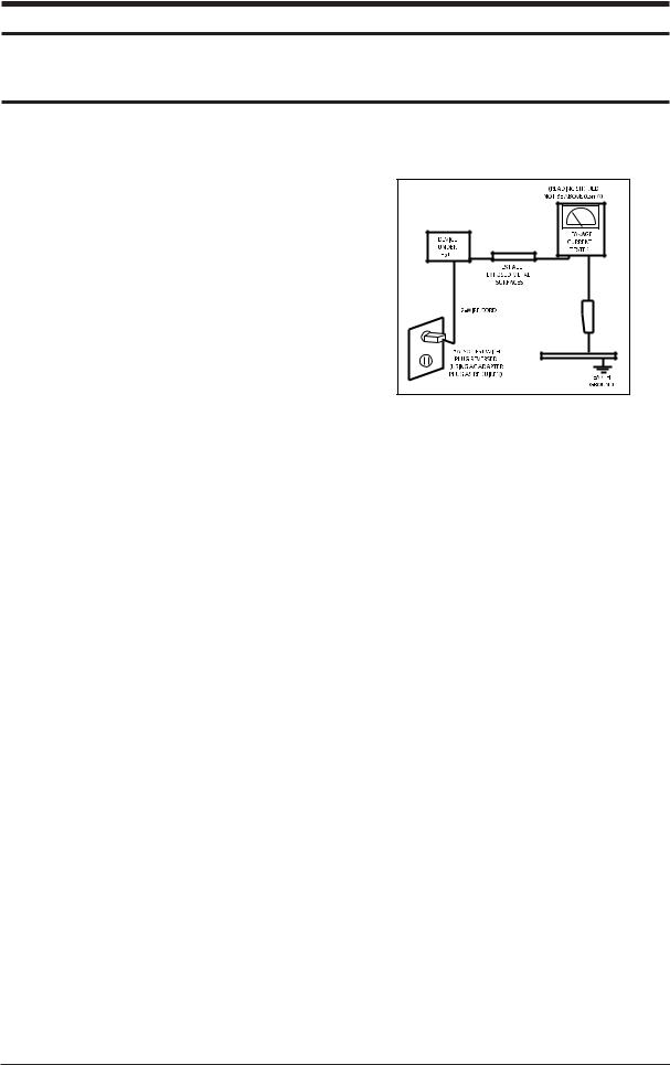
2-7 Option Specification
Item |
Item Name |
Code.No |
Remark |
Remote Control
& BN59-00507A
Batteries (AAA x 2)
Power Cord |
3903-000042 |
Cleaning Cloth |
BN63-001798A |
Owner's
Instructions BN68-00983A
27" : BN90-01005A
Stand 32" : BN90-00967A 37" : BN90-00966A
40" : BN90-00966A
27" : BN63-02415B
Cover-Bottom 32" : BN63-02415B 37" : BN63-02416B
40" : BN63-02416B
2-7

2 Product Specifications
Memo
2-8

3 Alignments and Adjustments
3 Alignments and Adjustments
3-1 Service Instruction
1.Usually, a color TV-VCR needs only slight touch-up adjustment upon installation. Check the basic characteristics such as height, horizontal and vertical sync.
2.Use the specified test equipment or its equivalent.
3.Correct impedance matching is essential.
4.Avoid overload. Excessive signal from a sweep generator might overload the front-end of the TV. When inserting signal markers, do not allow the marker generator to distort test result.
5.Connect the TV only to an AC power source with voltage and frequency as specified on the backcover nameplate.
6.Do not attempt to connect or disconnect any wire while the TV is turned on. Make sure that the power cord is disconnected before replacing any parts.
7.To protect aganist shock hazard, use an isolation transform.
3-1
3 Alignments and Adjustments
3-2 How to Access Service Mode
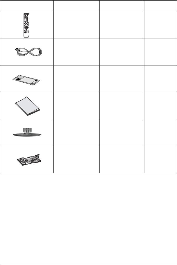
3-2-1 Entering Factory Mode
1.To enter "Service Mode" Press the remote -control keys in this sequence : - If you do not have Factory remote - control
INFO  MENU
MENU  MUTE
MUTE 
-If you have Factory remote - control
-The buttons are active in the service mode.
1.Remote - Control Key : Power, Arrow Up, Arrow Down, Arrow Left
Arrow Right, Menu, Enter, Number Key(0~9) 2. Function - Control Key : Power, CH +, CH -, VOL +, VOL -,
Menu, TV/VIDEO(Enter)
3-2-2 Panel Check
Specially for LE26,32R7**, You have to check Panel Maker Because of different adjustments as follows. First of all, Check the label rating!
1) Label Rating File
PANEL MAKER
|
|
|
|
|
If Panel Mark is "A", Set the factory mode |
|
Panel BOM(Bill of material) : BN07-00247A |
||
|
||||
indicating as follows. |
|
Connector between Panel and Power Unit |
||
|
|
|
|
: BN39-00603M (300mm) |
Panel BOM(Bill of material) : BN07-00289A |
|
* Option Byte |
||
Connector between Panel and Power Unit |
|
1. Gamma "AMLCD" |
||
: BN39-00603M (300mm) |
|
2. Panel Option "AMLCD_INT" |
||
|
|
|
|
If Panel Mark is "C" , Set the Factory mode |
* Option Byte |
|
indicating as follows. |
||
1. Gamma "AUO" |
|
Panel BOM(Bill of Material) : BN07-00207A |
||
2. Panel Option "AUO" |
|
Connecotor between Panel and Powe Unit : |
||
|
|
|
|
BN39-00659A(200mm) |
If Panel Mark is "S" or not printed. |
|
* Option Byte |
||
Set the factory mode indicating as follows. |
|
1. Gamma " CMO " |
||
|
|
|
|
2. Panel Option " CMO " |
|
|
|
|
Others are same shown below. |
|
|
|
|
|
3-2 |
|
|
|
|

3 Alignments and Adjustments
3-3 Factory Data
1. |
Calibration |
|
2. |
Option Table |
XXXX XXXX |
3.White Balance
4.SVP-FX
5.Option Block
6.STV8257/STA323W
7.YC Delay
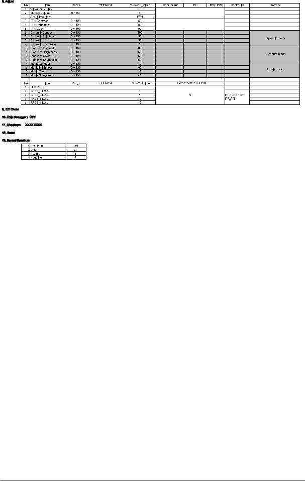
8.Adjust
9.I2C Check
10.W/B MOVIE
11.Checksum
12.Reset
13.Spread Spectrum
T-MILMPEU-1006 (Main Micom Ver)
T-MILMPEUS-1002 (Sub Micom Ver)
Month / Day / Year / Hour / Min. / Sec.
1.Calibration
1)AV Calibration
2)DTV Calibration
3)PC Calibration
2. Option Table |
XXXX XXXX |
|
|
|
|
|
|
|
|
|
|
Inch Option |
32" |
Carrier Mute |
ON |
TTX Group |
Auto |
|
|
|
|
|
|
Gamma |
OFF |
Language |
English |
Auto Power |
ON |
Panel Option |
AMLCD_INT |
Auto FM |
ON |
---- |
OFF |
|
|
|
|
|
|
2HDMI |
OFF |
High Deviation |
OFF |
---- |
G |
|
|
|
|
|
|
Brt.Sensor |
OFF |
TTX |
ON |
---- |
OFF |
EnergySave |
ON |
TTX List |
ON |
Debug |
OFF |
|
|
|
|
|
|
LBE/FBE |
OFF |
ACR |
OFF |
Ch.Table |
SUWON |
|
|
|
|
|
|
FRC(Micronas) |
OFF |
Dynamic CE |
ON |
iDTV_Cntry |
UK |
|
|
|
|
|
|
FRC(Samsung) |
OFF |
Dynamic Dimming |
ON |
Dynamic Contrast |
OFF |
|
|
|
|
|
|
LNA |
OFF |
Tuner TOP |
10 |
|
|
|
|
|
|
|
|
3-3

3 Alignments and Adjustments
3-4
3 Alignments and Adjustments
3-5
3 Alignments and Adjustments
3-4 Service Adjustment
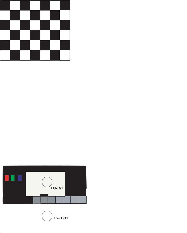
3-4-1 White Balance - Calibration
If picture color is wrong, do calibration first.
Equipment : CA210, Patten : chess pattern
Execute calibration in Factory Mode
Source AV : PAL composite, Component : 1280*720/60Hz
PC : 1024*768/60Hz
( chess patten )
3-4-2 White Balance - Adjustment
If picture color is wrong, check White Balance condition.
Equipment : CA210, Patten : Toshiba
Adjust W/B in Factory Mode
Sub brightness and R/G/B Offset controls low light region
Sub contrast and R/G/B Gain controls high light region
Source AV : PAL composite, Component : 1280*720/60Hz
HDMI[DVI] : 1280*720/60Hz
[ Test Pattern : MSPG-945 Series Pattern #16 ]
*Color temperature
1500K +/-500, -6 ~-20 MPCD
|
*Color coordinate |
|
|
H/L : 267/263 +/- 2 |
35.0 Ft +/- 2.0Ft |
|
||
|
L/L : 270/260 +/- 3 |
1.5 Ft +/- 0.2Ft |
|
Toshiba Patten |
|
|
|
|
3-6
3 Alignments and Adjustments
3-4-3 Conditions for Measurement
1.On the basis of toshiba ABL pattern : High Light level (57 IRE) - INPUT SIGNAL GENERATOR : MSPG-925LTH
* Mode |
NO |
2 |
: 744X484@60 Hz |
|
NO |
6 |
: 1280X720@60 Hz |
|
NO 21 |
: 1024X768@60 Hz |
|
* Pattern |
NO |
36 |
: 16 Color Pattern |
|
NO |
16 |
: Toshiba ABL Pattern |
2.Optical measuring device : CA210 (FL)
Please use the MSPG-925 LTH generator for model LE26M51B/LE32M51B/LE40M51B/LE46M51B.
3-4-4 Method of Adjustment
1. Adjust the white balance of AV, Component and DVI Modes.
(AV  Component)
a) Set the input to the mode in which the adjustment will be made (RF  DTV
DTV  PC
PC  DVI).
DVI).
*Input signal - VIDEO Mode : Model #2 (744*484 Mode), Pattern #16
-DTV,DVI Mode : Model #6 (1280*720 Mode), Pattern #16
-HDMI Mode: Model #6(1280*720 Mode), Pattern #16
b)Enter factory color control, confirm the data.
c)Adjust the low light. (Refer to table 1, 2 in adjustment position by mode)
-Adjust sub - Brightness to set the 'Y' value.
-Adjust red offset ('x') and blue offset ('y') to the color coordinates.
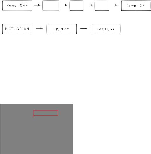
Picture 4-2 Toshiba ABL Pattern
Low light
Measurement point
*Do not adjust green offset data.
d)Adjust the high light. (Refer to table 1, 2 in adjustment position by mode) - Adjust red gain ('x') and blue gain ('y') to the color coordinates.
*Do not adjust the green gain and sub-contrast (Y) data.
3-7

3 Alignments and Adjustments
d)Adjust the high light. (Refer to table 1, 2 in adjustment position by mode) - Adjust red gain ('x') and blue gain ('y') to the color coordinates.
* Do not adjust the green gain and sub-contrast (Y) data.
Picture 4-3 Toshiba ABL Pattern
High light
Measurement point
3-8

3 Alignments and Adjustments
3-5 Software Upgrade
3-5-1 How to Update Flash ROM
1.Installthe Flash Downloader
ConnectSet(Service Jack)and Jig Cable to execute Program Update.
2.Flash Downloader program update
-Before Turning on the set,Click "connect"which is under of OSD Screen! -Turn on the Set.
3-9

3 Alignments and Adjustments
Memo
3-10

4 Troubleshooting
4 Troubleshooting
4-1 First Checklist for Troubleshooting
1.Check the various cable connections first.
-Check to see if there is a burnt or damaged cable.
-Check to see if there is a disconnected cable connection or a connection is too loose.
-Check to see if the cables are connected according to the connection diagram.
2.Check the power input to the Main Board.
3.Check the voltage in and out between the SMPS
 Main Board, between the SMPS
 INVERTER Board, and between the Main LVDS Boards.
4-1
4 Troubleshooting
4-2 Checkpoints by Error Mode
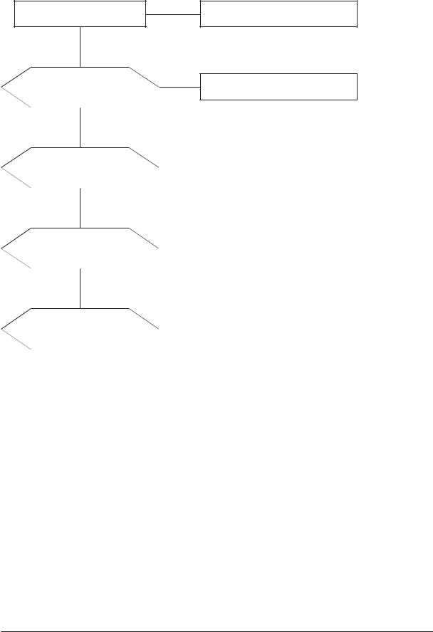
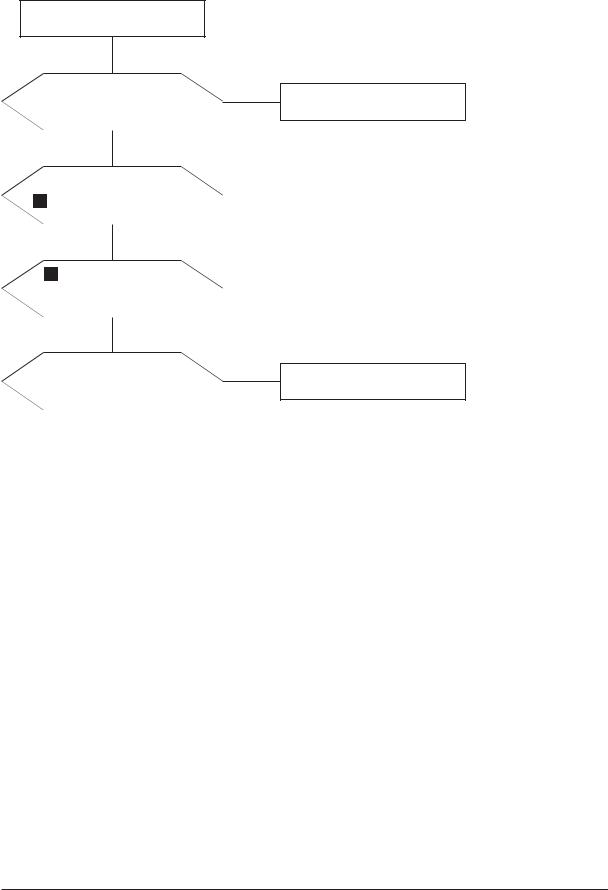
4-2-1 No Power
LAMP off, power indicator LED red color?
Yes
Does proper DC 12V appear at CN800?
Yes
Does proper DC A3.3V, A5V appear at C854, C866?
Yes
Does proper DC 5V, 3.3V, 1.8V appear at C811, C853, C833?
Yes
A power is supplied to set?
No
Check a connection a power cable.
No
Change a Assy PCB Power.
No |
Check a IC809, IC802. |
|
|
|
Change a main PCB ass'y. |
|
|
No |
Check a IC803, IC805, IC813, IC307. |
|
|
|
Change a main PCB ass'y |
|
|
No |
Check a other function. |
|
(No picture part) |
|
|
|
Replace a lcd panel. |
|
|
4-2
4 Troubleshooting
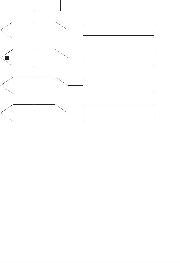
4-2-2 No Video (Analog PC)
Power Indicator is off.
Lamp on, no video.
Yes
Check a PC source and check the connection of DSUB cable?
Yes
Does the signal appear at 1 #30, 22, 38(R, G, B) of IC500?
Yes
Does the digital data appear at the output of
LVDS (R563_OP~R572_OP)?
Yes
Check a LVDS cable?
Replace a lcd panel?
No
No
No
No
Input a analog PC signal and connected cable(DPMS).
PC cable. Change a PC cable. Change a main PCB ass'y.
Check a IC500 Change a main PCB ass'y.
Please, Call to Samsung Co. LTD.
4-3
4 Troubleshooting
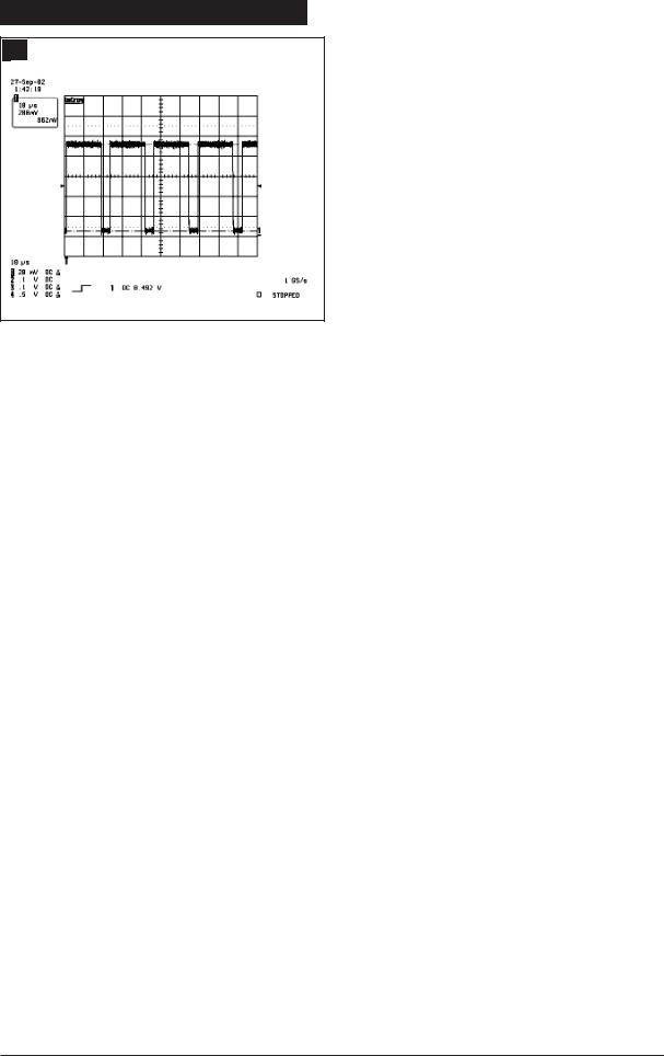
WAVEFORMS
1 R,G,B Output Signal of IC500
4-4
4 Troubleshooting
4-2-3 No Video (Digital-HDMI)
Power Indicator is off.
Lamp on, no video.
Yes
Check the connection of HDMI cable?
Yes
Does the digital data appear at 3 R503~R510?
Yes
2 Does the digital data appear at output of IC500
LVDS(R563_OP~R572_OP)?
Yes
Check a LVDS cable?
Replace lcd panel?
No
Input a HDMI cable.
No |
Check a a IC 500 |
|
|
|
Change a main PCB ass'y. |
|
|
No |
Check a IC500 |
|
|
|
Change a main PCB ass'y. |
|
|
No
Please, Call to Samsung Co. LTD.
4-5
4 Troubleshooting
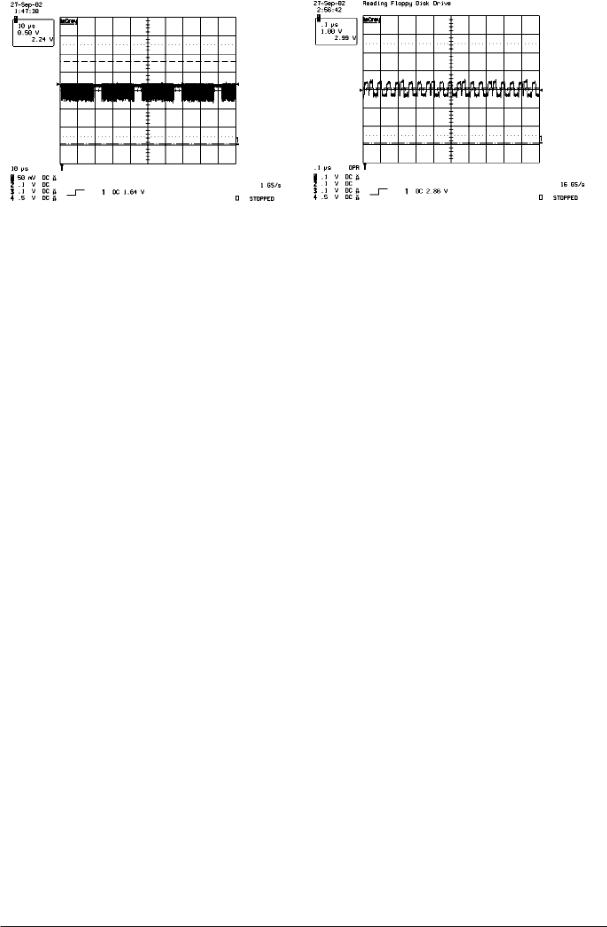
2 |
Digital Output Data of IC500 |
|
3 |
Signal of HDMI(Data) |
||||
|
|
|
|
|
|
|
|
|
|
|
|
|
|
|
|
|
|
4-6
 Loading...