


450 Series
Samsung 450 Series, 460 Series, 478Series, 470 Series, 670Series Installation Manual
...
LED TV
Installation manual
Thank you for purchasing this Samsung product.
To receive more complete service, please
register your product at
www.samsung.com/register
Model Serial No.
450
460
470/477/478
670/677/678
Figures and illustrations in this User Manual are provided for reference only and may differ from actual product
appearance. Product design and specifications may be changed without notice.
Introduction
This TV B2B (Business to Business) model is designed for hotels or the other hospitality businesses, supports a variety of
special functions, and lets you limit some user (guest) controls.
Operational Modes
This TV has two modes : Interactive and Stand-alone mode.
• Interactive mode : In this mode, the TV communicates with and is fully or partially controlled by a connected Set
Back Box (SBB) or Set Top Box (STB) provided by a hospitality SI (System Integration) vendor. When the TV is initially
plugged in, it sends a command that attempts to identify the SSB or STB connected to it. If the TV identifies the SBB
or STB and the SBB or STB identifies the TV, the TV gives full control to the SBB or STB.
• Stand-alone mode : In this mode, this TV works alone without an external SBB or the STB.
The TV has a Hotel (Hospitality) Menu that lets you easily set its various hospitality functions. Please see pages 28 to 33.
The Menu also lets you activate or de-activate some TV and hospitality functions so you can create your optimal hospitality
configuration.
Still image warning
Avoid displaying still images (such as jpeg picture files) or still image elements (such as TV channel logos, panorama or 4:3
format images, stock or news bars etc) on the screen. Displaying still pictures continually can cause uneven screen wear,
which will affect image quality. To reduce the chance that this effect will occur, please follow the recommendations below:
• Avoid displaying the same TV channel for long periods.
• Always try to display a full screen image.
• Reduce brightness and contrast to help to prevent the occurrence of after-images.
• Frequently use all TV features designed to reduce image retention and screen burn-in. Refer to the proper user
manual section for details.
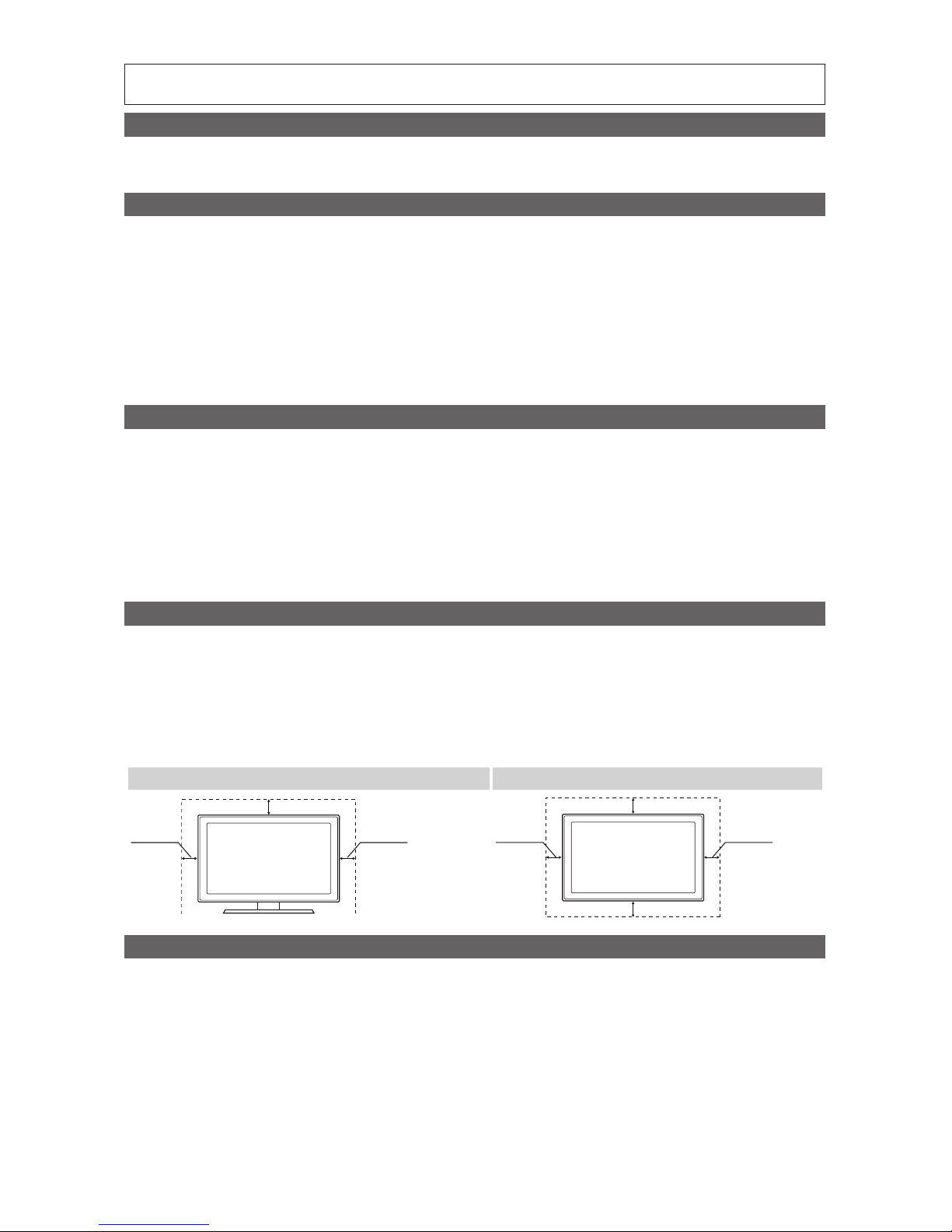
Ensuring Proper Ventilation
When you install the TV, maintain a distances of at least 4 inches between the TV and other object (walls, cabinet sides, etc.)
to ensure proper ventilation.
Failing to maintain proper ventilation may result in a fire or problems with the product caused by an increase in its internal
temperature.
✎ When using a stand or wall-mount, use parts provided by Samsung Electronics only.
✎ Using parts provided by another manufacturer may cause difficulties with the product or result in injury caused by the
product falling.
Installation with a stand Installation with a wall-mount
4 inches4 inches
4 inches
4 inches4 inches
4 inches
4 inches
Additional Information
✎ The appearance of the TV and its accessories may differ from the illustrations in this manual, depending on the TV.
✎ Be careful when the you touch the TV. Some parts can be hot.

3
Contents
ENGLISH
English
y Introduction ................................................................................................................................................. 2
y Operational Modes ...................................................................................................................................... 2
y Still image warning ....................................................................................................................................... 2
y Ensuring Proper Ventilation .......................................................................................................................... 2
y Additional Information .................................................................................................................................. 2
y Accessories ................................................................................................................................................. 4
y Installing the LED TV Stand.......................................................................................................................... 5
y Assembling the swivel stand (470 and above models with 32" or lager TVs) ................................................ 9
y Using the TV's Controller ........................................................................................................................... 11
y The Connection Panel ............................................................................................................................... 12
y Using the TV's remote Controller ............................................................................................................... 19
y Connecting the TV to the Lodgenet game controller or a STB of a SI vendor ............................................ 21
y Connecting the Audio Output to an Audio Amplifier ................................................................................... 23
y Connecting the RJP (Remote Jack Pack) .................................................................................................. 24
y Setting the Hotel Option Data .................................................................................................................... 27
y Installing the Wall Mount ............................................................................................................................ 53
y Securing the TV to the Wall ........................................................................................................................ 54
y Anti-theft Kensington Lock ........................................................................................................................ 55
y Specifications ............................................................................................................................................ 56
y Dimensions ................................................................................................................................................ 60
4
English
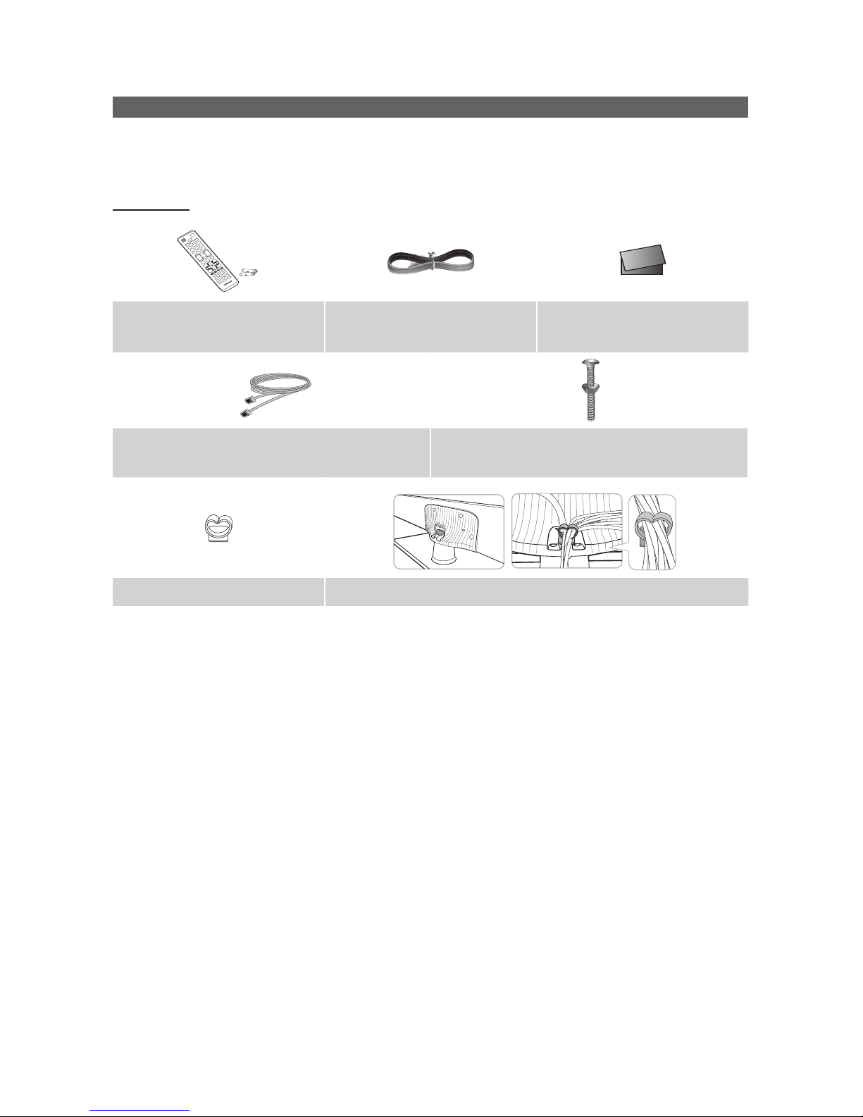
Accessories
✎ Please make sure the following items are included with your LED TV. If any items are missing, contact your dealer.
✎ The items’ color and shape may vary, depending on the model.
✎ The parts for the stand are listed under Stand Components on the following page.
List of Parts
Remote Control & Batteries (AAA x 2) Power Cord
Safety Guide / Quick Setup Guide
(Not available in all locations)
Data Cable (depending on the model)
(BN39-00865B, BN39-01011E)
Hotel Mount Kit
(Depending on the Model)
Holder-Wire stand 1(EA) Assembling the Holder Wire Stand
5
English
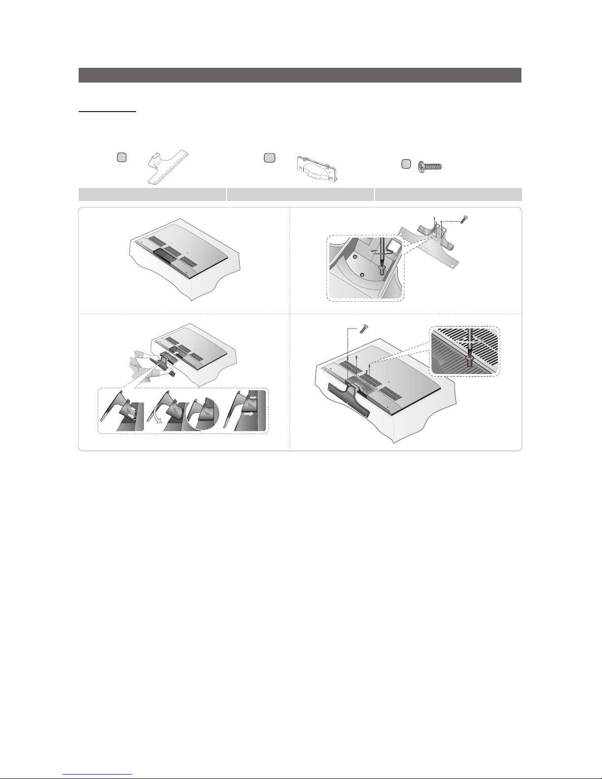
Installing the LED TV Stand
Components
When installing the stand, use the provided components and parts.
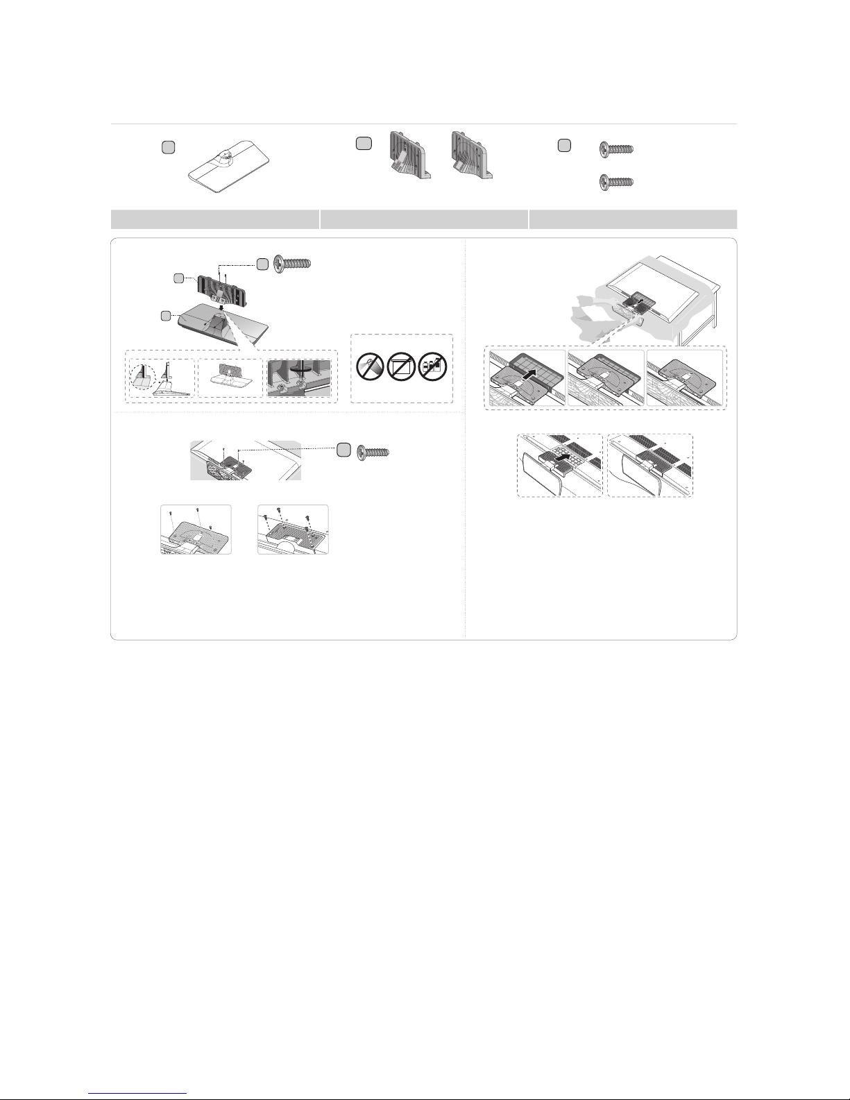
♦ HG40ND450
A
B
C
X 7 (M4 X L12)
Stand Guide Stand Screws
1
3
4
2
X 3 (M4 X L12)
X 4 (M4 X L12)
6
English
♦ HG28ND460 / HG40ND460
A
28" 40"
B
28”
or
40”
C
X 7 (M4 X L12)
X 8 (M4 X L14)
Stand Guide Stand Screws
C
28”: X4 (M4 X L12)
40”:
X
4 (M4 X L14)
B
A
DO NOT USE
GREASE
Attention
DO NOT USE
CHEMICALS
DO NOT USE
OIL
✎ Place a soft cloth over the table to protect
the TV, and then place the TV on the cloth
screen-side down.
✎ Insert the Stand Guide into the slot on the
bottom of the TV.
✎ Slide and assemble it to the end line in the
direction of arrow.
1 2
3
C
28”:
X3 (M4 X L12)
40”: X4 (M4 X L14)
✎ Tight the bottom of the screw first, and stow the up-
per side of screw last.
✎ Progress the assembly of screw in the manual’s
order.
28”
28”
40”
40”
7
English
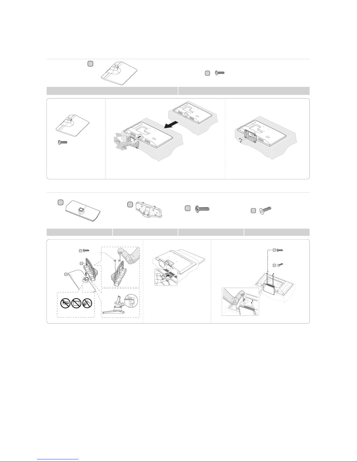
♦ HG24ND470 / HG32ND470 / HG40ND470 / HG32ND477 / HG40ND477/ HG32ND478 / HG40ND478
(for 24” models)
A
X 3 (M4 x L12, for 24” models)
B
Stand Screws
1
2 3
✎ Place a soft cloth over the table to protect the TV, and then
place the TV on the cloth screen-side down.
✎ Insert the Stand Guide into the slot on the bottom of the TV.
X 3 (M4 x L12)
(for 32” and above models)
A
B
C
x8 (M4 x L12)
D
x 4 (M4 x L12)
Stand Guide Stand Screws Security Screws
B
A
Front
1
2 3
C
(M4 X L12)
x4
TOP
View
Side
C
D
x 4 (M4 x L12)
or
x 4 (M4 x L12)
Attention
DO NOT USE
CHEMICALS
DO NOT USE
GREASE
DO NOT USE
OIL
✎ Place a soft cloth over the table
to protect the TV, and then place
the TV on the cloth screen-side
down.
✎ Insert the Stand Guide into the
slot on the bottom of the TV.
8
English
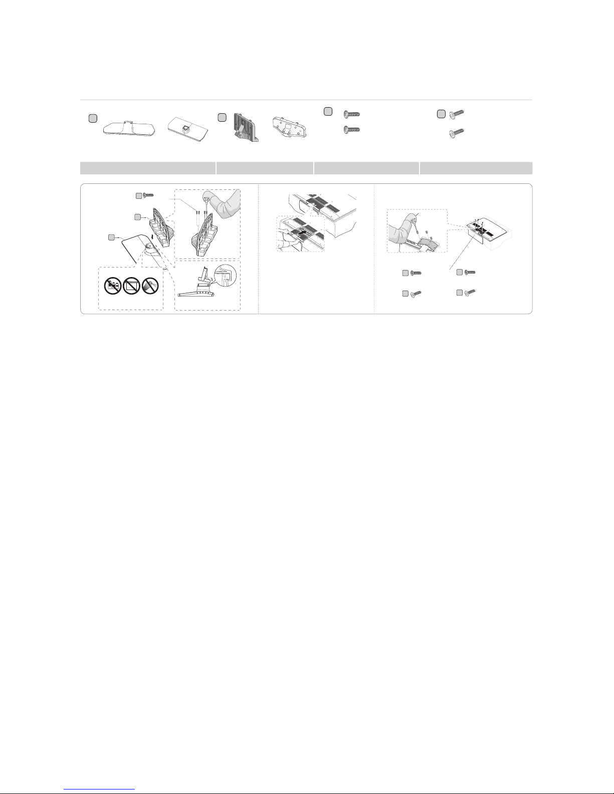
♦ HG28ND670 / HG40ND670 / HG48ND670 / HG28ND677 / HG40ND677 / HG48ND677 / HG55ND677 /
HG40ND678 / HG48ND678 / HG55ND678
A
or
1EA
40”~55”
28”
1EA
or
B
40”~55”28”
C
x7 (M4 X L12)
or
x8 (M4 X L12,
for 40” and
above models)
D
x3(M4 X L12)
x4(M4 X L12,
for 40” and
above models)
or
Stand Guide Stand Screws Security Screws
✎ P
lace a soft cloth over the table to
protect the TV, and then place the
TV on the cloth screen-side down.
✎ Insert the Stand Guide into the
slot on the botton of the TV.
Front
1
2 3
C
B
A
(M4 X L12)
x4
TOP View
Side
(M4 X L12)
x3
(M4 X L12, for 40” and
above models)
x4
or
(only for 40” and above models)
DO NOT USE
OIL
DO NOT USE
GREASE
DO NOT USE
CHEMICALS
Attention
(Security Screw, for 40”
and above models)
x4
(Security Screw)
x3
C
C
D
D
✎ NOTE
• Make sure to distinguish between the front and back of the Stand and Stand Guide when connecting them.
• Make sure that at least two people lift and move the LED TV.
• The number of screws may differ depending on the model.
9
English
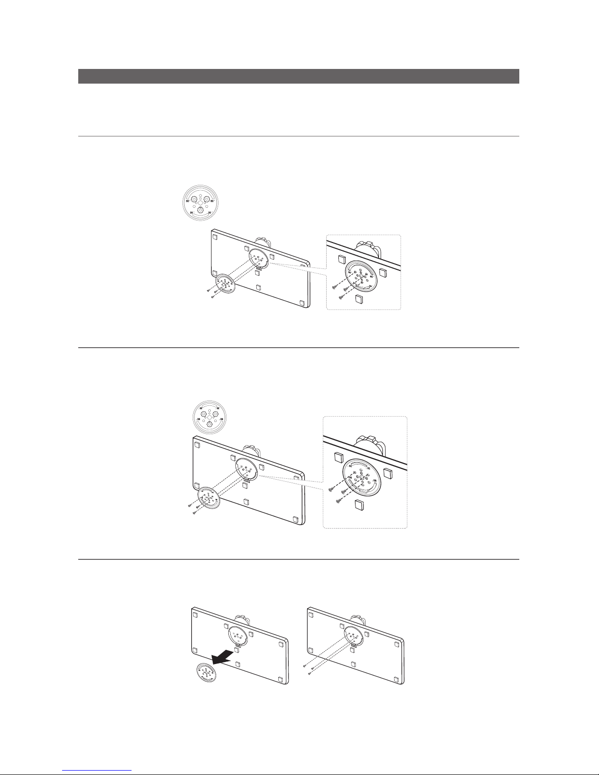
Assembling the swivel stand (470 and above models with 32" or lager TVs)
The 470 and above models with 32" or lager TVs have swivel stands. You can configure these stands so that the TVs swivel
20 degrees left and right, 60 degrees left and right, or 90 degrees left and right using the BRACKET HOLDER SWIVEL.
¦ 20° swivel
To configure the TV so that it swivels 20° left and right, insert the prong on the bottom of the stand through the curved hole
in the Bracket Holder Swivel marked 20°. Then, fix the Bracket Holder Swivel to the stand using the three supplied screws
as shown to the left.
¦ 60° swivel
To configure the TV so that it swivels 60° left and right, insert the prong on the bottom of the stand through the curved hole
in the Bracket Holder Swivel marked 60°. Then, fix the Bracket Holder Swivel to the stand using the three supplied screws
as shown to the left.
¦ 90° swivel
To configure the TV so that it swivels 90° left and right, remove the Bracket Holder Swivel, and then screw the three supplied
screws into the stand as shown to the left.
10
English
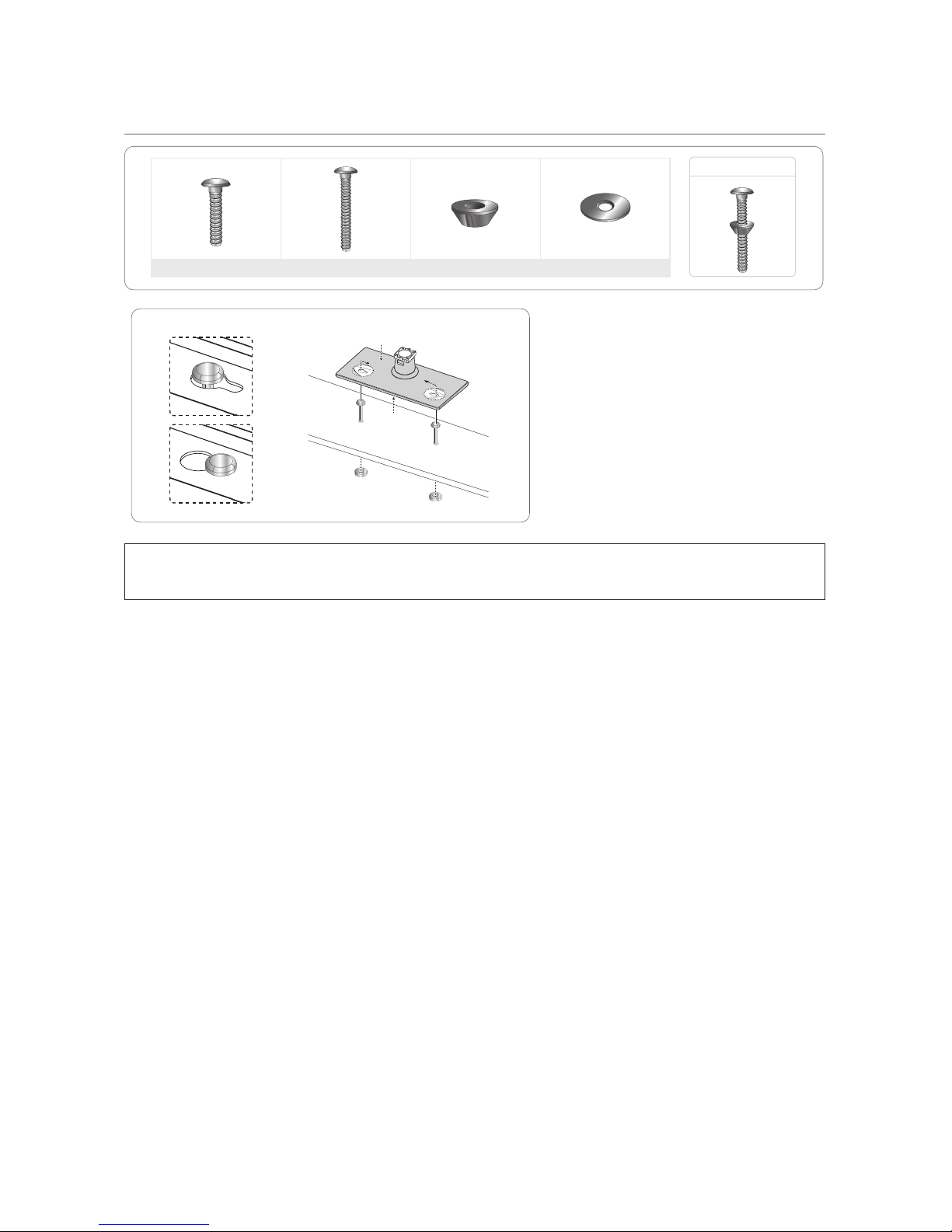
¦ Hotel Mount Kit (not necessary for all models)
Bolt + Nut
Short Bolt (2EA) Long Bolt (2EA) Nut (2EA) Washer (2EA)
Top
Bottom
Affix the stand to a flat surface such as a
dresser top, desk top, or entertainment center
as shown.
[
WARNING: To prevent injury, you must attach this TV securely to the floor, a table, a dresser top, etc.
with the Hotel Mount Kit as described in these instructions.
11
English
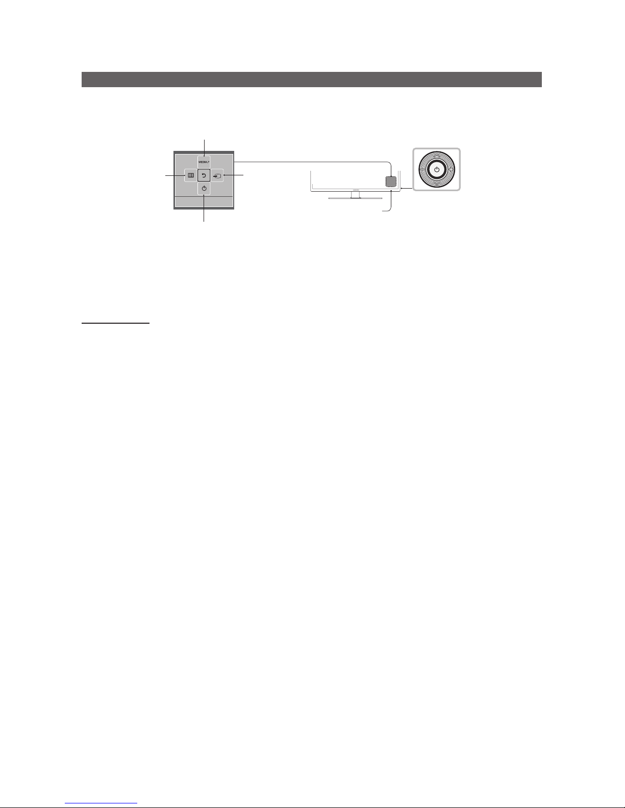
Using the TV's Controller
The TV’s Controller, a small joy stick like button on the rear right side of the TV, lets you control the TV without the remote
control.
TV Controller
The image is drawn
as if you are facing the
front side of the TV.
Power off
Function menu
Remote control sensor
Return
Selecting the
Media Play
Selecting the
Menu
Select a source.
✎ The product color and shape may vary depending on the model.
✎ To exit the menu, press the Controller for more than 1 second.
✎ When selecting a function by moving the controller up/down/left/right, be sure not to press up on the controller. If
you press up first, it will not operate correctly.
Standby mode
Your TV enters Standby mode when you turn it off and continues to consume a small amount of electric power. To be safe
and to decrease power consumption, do not leave your TV in standby mode for long periods of time (when you are away on
vacation, for example). It is best to unplug the power cord.
12
English
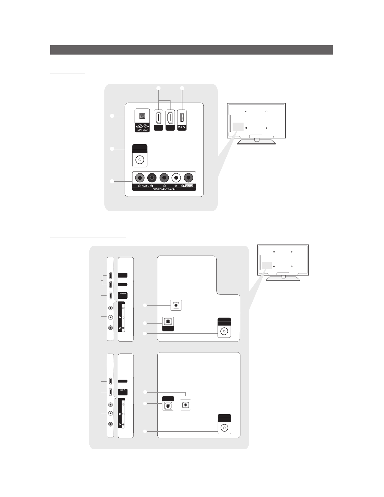
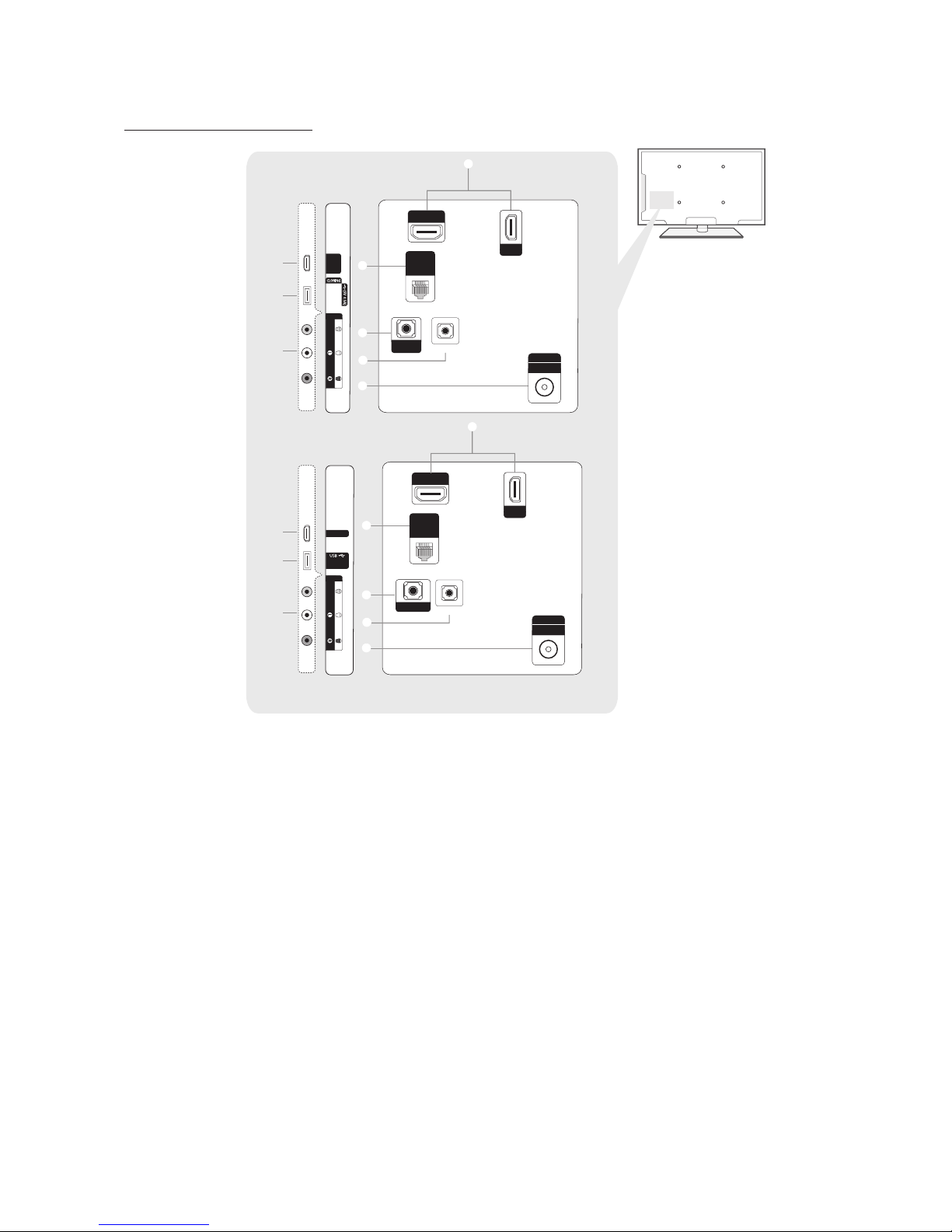
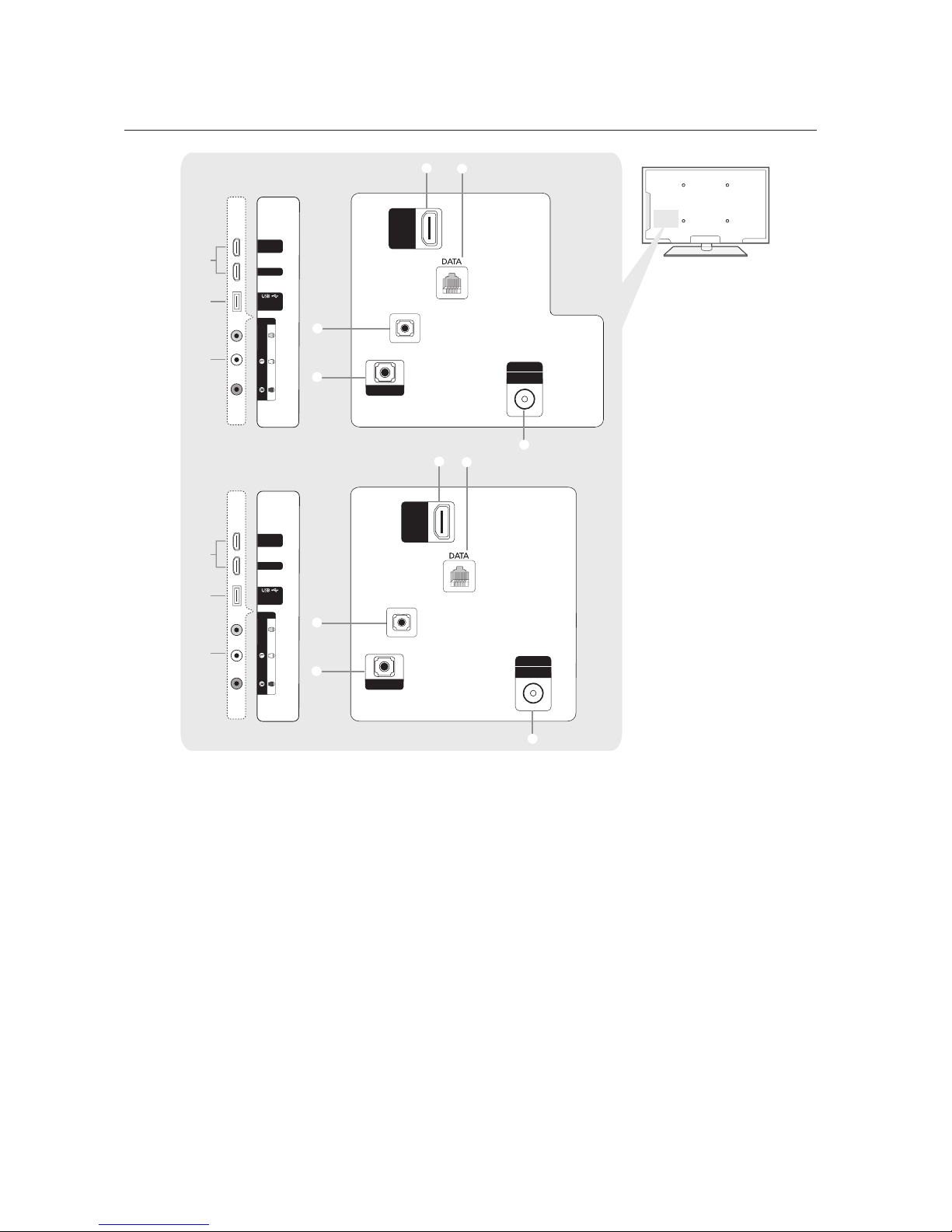
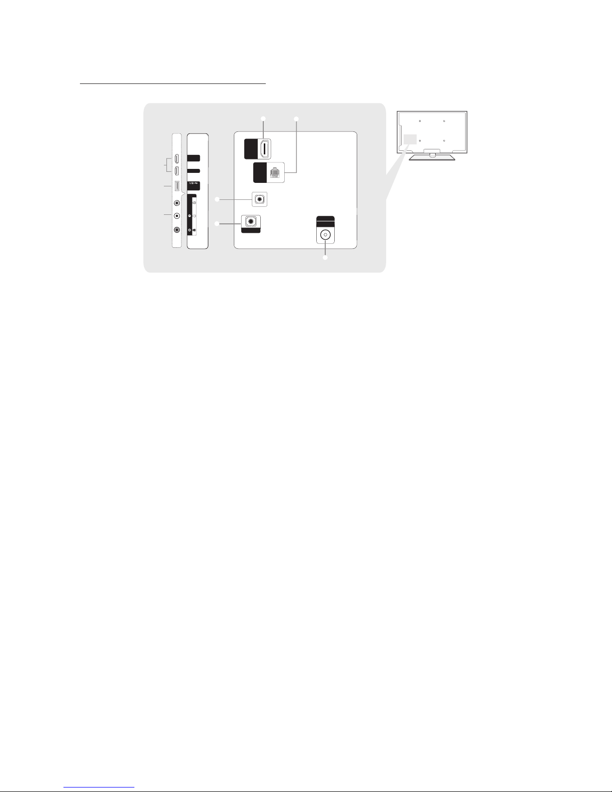
The Connection Panel
HG40ND450
6
9
1 2
0
ANT IN
AIR/CABLE
HDMI IN
1 (STB)
HDMI IN
2 (DVI)
(5V 0.5A)
HG28ND460 / HG40ND460
3
4
HDMI IN 1
HDMI IN 2
(DVI)
2
(5V 0.5A)
/CLONING
1
AV IN
AUDIO
VIDEIO
EX-LINK
AUDIO
OUT
5
6
ANT IN
AIR/CABLE
3
4
HDMI IN
2
(5V 0.5A)
/CLONING
1
AV IN
AUDIO
VIDEO
EX-LINK
5
6
ANT IN
AIR/CABLE
AUDIO
OUT
HD460 28” MODEL USE
HD460 40” MODEL USE
13
English
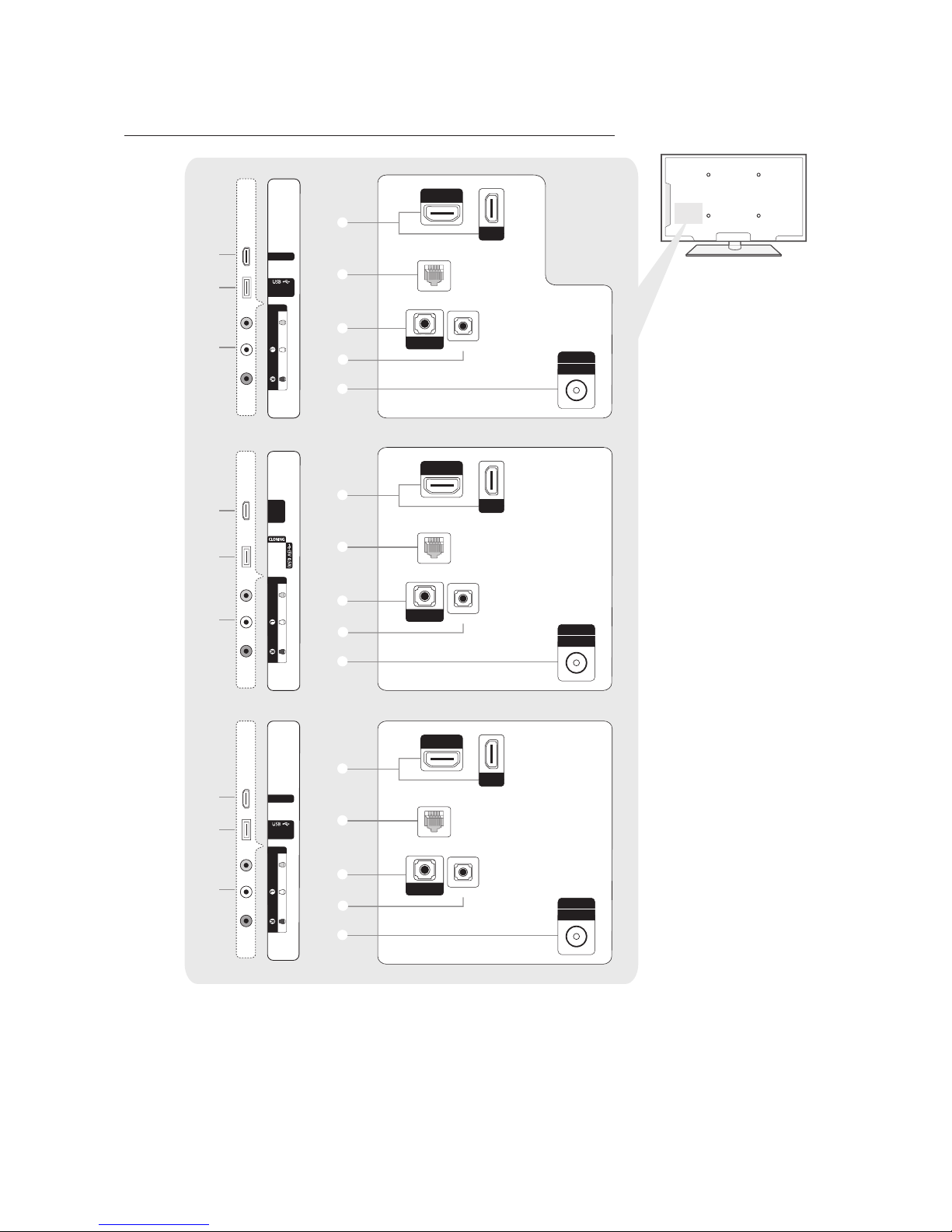
HG24ND470 / HG32ND470 / HG40ND470 / HG32ND477 / HG40ND477
3
HDMI IN 1
2
(5V 0.5A)
/CLONING
1
AV IN
AUDIO
VIDEO
4
EX-LINK
AUDIO OUT
5
7
1
6
ANT IN
AIR/CABLE
DATA
HDMI IN 3
(ARC)
HDMI IN 2
(DVI)
4
EX-LINK
AUDIO OUT
5
7
1
6
ANT IN
AIR/CABLE
DATA
HDMI IN 3
(ARC)
HDMI IN 2
(DVI)
3
2
HDMI IN 1
1
AV IN
AUDIO
VIDEO
4
EX-LINK
AUDIO OUT
5
7
1
6
ANT IN
AIR/CABLE
DATA
HDMI IN 3
(ARC)
HDMI IN 2
(DVI)
3
HDMI IN 1
2
(5V 0.5A)
/CLONING
1
AV IN
AUDIO
VIDEO
HD470 24" MODEL USE
HD470/477 32” MODEL USE
HD470/477 40”MODEL USE
14
English
HG32ND478 / HG40ND478
3
4
2
HDMI IN 1
1
AV IN
AUDIO
VIDEO
EX-LINK
AUDIO
OUT
5
8
6
ANT IN
AIR/CABLE
HDMI IN 3
(ARC)
1
GAME
CONTROL
DATA
HDMI IN 2
(DVI)
3
4
HDMI IN 1
2
(5V 0.5A)
/CLONING
1
AV IN
AUDIO
VIDEO
EX-LINK
AUDIO OUT
5
8
6
ANT IN
AIR/CABLE
HDMI IN 3
(ARC)
GAME
CONTROL
DATA
HDMI IN 2
(DVI)
1
HD478 32" MODEL USE
HD478 40” MODEL USE
15
English
HG28ND670 / HG40ND670 / HG48ND670 / HG28ND677 / HG40ND677 / HG48ND677 / HG55ND677
3
4
HDMI IN 1
HDMI IN 2
(DVI)
2
(5V 0.5A)
/CLONING
1
AV IN
AUDIO
VIDEIO
HDMI IN
3 (ARC)
EX-LINK
AUDIO OUT
5
ANT IN
AIR/CABLE
1
6
7
3
4
HDMI IN 1
HDMI IN 2
(DVI)
2
(5V 0.5A)
/CLONING
1
AV IN
AUDIO
VIDEO
HDMI IN
3 (ARC)
1
7
EX-LINK
AUDIO OUT
5
ANT IN
AIR/CABLE
6
HD670/HD677 40”/48”/55” MODEL USE
HD670/HD677 28” MODEL USE
16
English
HG40ND678 / HG48ND678 / HG55ND678
3
4
HDMI IN 1
HDMI IN 2
(DVI)
2
(5V 0.5A)
/CLONING
1
AV IN
AUDIO
VIDEO
EX-LINK
AUDIO OUT
5
ANT IN
AIR/CABLE
HDMI IN
3 (ARC)
1
6
GAME
CONTROL
DATA
8
✎ Connect an external device to your TV, make sure that the TV and the device are turned off.
✎ When connecting an external device, match the color of the connection terminal to the cable.
1 HDMI IN
– Connects to the HDMI jack of a device with an HDMI output.
✎ No separate sound connection is needed for an HDMI to HDMI connection. HDMI connections carry both
audio and video.
2 USB / CLONING
– Connector for software upgrades and Media Play, etc.
– Service connection.
3 VIDEO / L-AUDIO-R
– Connect a VIDEO cable to an appropriate external A/V device such a VCR, DVD, or Camcorder.
– Connect audio cables to "L-AUDIO-R" on your TV and the other ends to corresponding audio out jacks on the A/V
device.
4 EX-LINK
– Connect this jack to the jack on the optional RJP (Remote Jack Pack). The RJP allows you to connect external
devices (Camcoders, PCs, DVD players, etc) easily.
5 AUDIO OUT
– Connects to the audio input jacks on an Amplifier/Home Theater.
6 ANT IN or AIR/CABLE
– To view television channels correctly, the TV must receive a signal from one of the following sources:
– An outdoor antenna / A cable television system / A satellite receiver.
7 DATA
– Used to support data communication between the TV and the external SBB or STB.
– Connects using an RJ-12 type of plug.
17
English
8 GAME CONTROL DATA
– Used to connect the Lodgenet game controller in the Lodgenet system or support data communication between
the TV and the external SBB or STB.
– Connects using an RJ-12 type of plug.
9 DIGITAL AUDIO OUT(OPTICAL)
– Use the optical cable to make audio connection.
0 COMPONENT/AV IN
– Used to connect with DVD players, Blu-ray players, cable boxes, STB satellite receivers, VCRs.
✎ For better picture quality, we recommend the Component connection over the A/V connection.
✎ When you connect a Video cable to COMPONENT / AV IN, the color of the COMPONENT / AV IN [VIDEO] jack
(green) will not match the video cable (yellow).
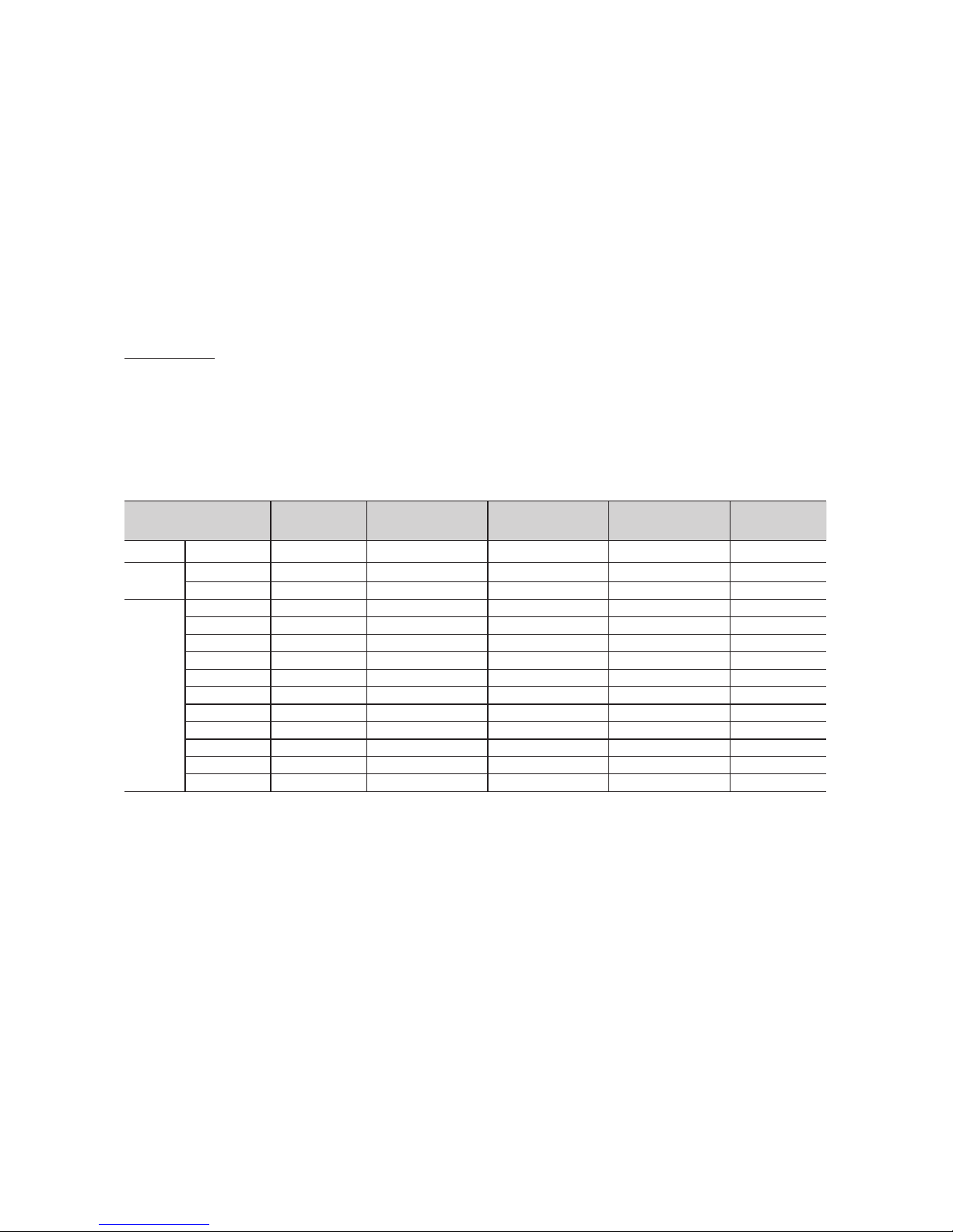
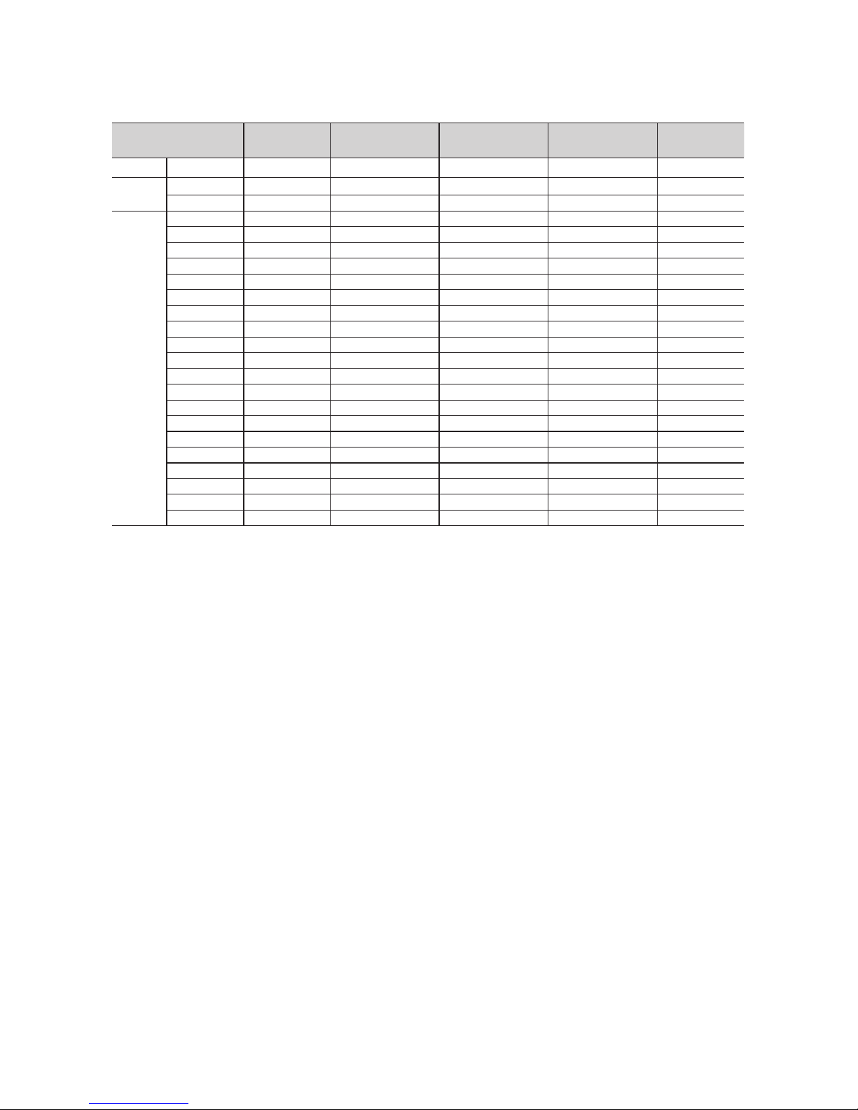
Display Modes
You can also select one of the standard resolutions listed in the Resolution column. The TV will automatically adjust to the
resolution you choose.
After connecting a computer to the TV, set the screen resolution for the TV on the computer. The optimal resolution is 1920
x 1080 @ 60 Hz. If it is set to any other than in the table below, the TV may display nothing. Set the resolution properly,
referring to the user guide of the computer or its graphic card.
The resolutions in the table are recommended.
✎ Optimal resolution is 1366 X 768 @ 60 Hz.
Display Mode Display Format
Horizontal Frequency
(kHz)
Vertical Frequency
(Hz)
Pixel Clock
(MHz)
Sync Polarity
(H/V)
IBM 720 x 400 70Hz 31.469 70.087 28.322 -/+
MAC
640 x 480 67Hz 35.000 66.667 30.240 -/-
832 x 624 75Hz 49.726 74.551 57.284 -/-
VESA
DMT
640 x 480 60Hz 31.469 59.940 25.175 -/-
640 x 480 72Hz 37.861 72.809 31.500 -/-
640 x 480 75Hz 37.500 75.000 31.500 -/-
800 x 600 60Hz 37.879 60.317 40.000 +/+
800 x 600 72Hz 48.077 72.188 50.000 +/+
800 x 600 75Hz 46.875 75.000 49.500 +/+
1024 x 768 60Hz 48.363 60.004 65.000 -/-
1024 x 768 70Hz 56.476 70.069 75.000 -/-
1024 x 768 75Hz 60.023 75.029 78.750 +/+
1280 x 720 60Hz 45.000 60.000 74.250 +/+
1366 x 768 60Hz 47.712 59.790 85.500 +/+
18
English
✎ Optimal resolution is 1920 X 1080 @ 60 Hz.
Display Mode Display Format
Horizontal Frequency
(kHz)
Vertical Frequency
(Hz)
Pixel Clock
(MHz)
Sync Polarity
(H/V)
IBM 720 x 400 70Hz 31.469 70.087 28.322 -/+
MAC
640 x 480 67Hz 35.000 66.667 30.240 -/-
832 x 624 75Hz 49.726 74.551 57.284 -/-
VESA
DMT
1152 x 870 75Hz 68.681 75.062 100.000 -/-
640 x 480 60Hz 31.469 59.940 25.175 -/-
640 x 480 72Hz 37.861 72.809 31.500 -/-
640 x 480 75Hz 37.500 75.000 31.500 -/-
800 x 600 60Hz 37.879 60.317 40.000 +/+
800 x 600 72Hz 48.077 72.188 50.000 +/+
800 x 600 75Hz 46.875 75.000 49.500 +/+
1024 x 768 60Hz 48.363 60.004 65.000 -/-
1024 x 768 70Hz 56.476 70.069 75.000 -/-
1024 x 768 75Hz 60.023 75.029 78.750 +/+
1152 x 864 75Hz 67.500 75.000 108.000 +/+
1280 x 720 60Hz 45.000 60.000 74.250 +/+
1280 x 800 60Hz 49.702 59.810 83.500 -/+
1280 x 1024 60Hz 63.981 60.020 108.000 +/+
1280 x 1024 75Hz 79.976 75.025 135.000 +/+
1366 x 768 60Hz 47.712 59.790 85.500 +/+
1440 x 900 60Hz 55.935 59.887 106.500 -/+
1600 x 900RB 60Hz 60.000 60.000 108.000 +/+
1680 x 1050 60Hz 65.290 59.954 146.250 -/+
1920 x 1080 60Hz 67.500 60.000 148.500 +/+
✎ When using an HDMI/DVI cable connection, you must use the HDMI IN (DVI) jack.
✎ The interlace mode is not supported.
✎ The set might operate abnormally if a non-standard video format is selected.
✎ Separate and Composite modes are supported. SOG is not supported.
19
English
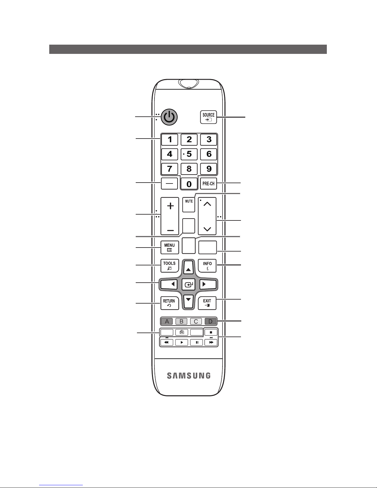
Using the TV's remote Controller
HOME
CONTENT
CH
LIST
ALARM
SLEEP CC
CHVOL
¢
Turns the TV on and off.
Display and select the available video
sources.
Return to the previous channel.
Change channels.
View the Contents Home.
Exit the menu.
Press to display channel and TV
information on the TV screen.
SLEEP: Sets the Sleep Timer.
X: Turns the 3D image on or off.
(Not available)
CC: Controls the caption decoder.
Cut off the sound temporarily.
Press to access channels directly.
Adjust the volume.
Display the channel list on the screen.
Display the main on-screen menu.
HOME: Switch to the HOME Screen.
(HD478/HD678 none)
Quickly select frequently used functions.
Return to the previous menu.
Use these buttons in a specific feature.
Select on-screen menu items and
change menu values.
Press to select additional digital
channels being broadcast by the same
station. For example, to select channel
‘54-3’, press ‘54’, then press '-' and ‘3’.
Use these buttons according to the
directions on screen (to perform a
function, display a screen, etc.).
20
English
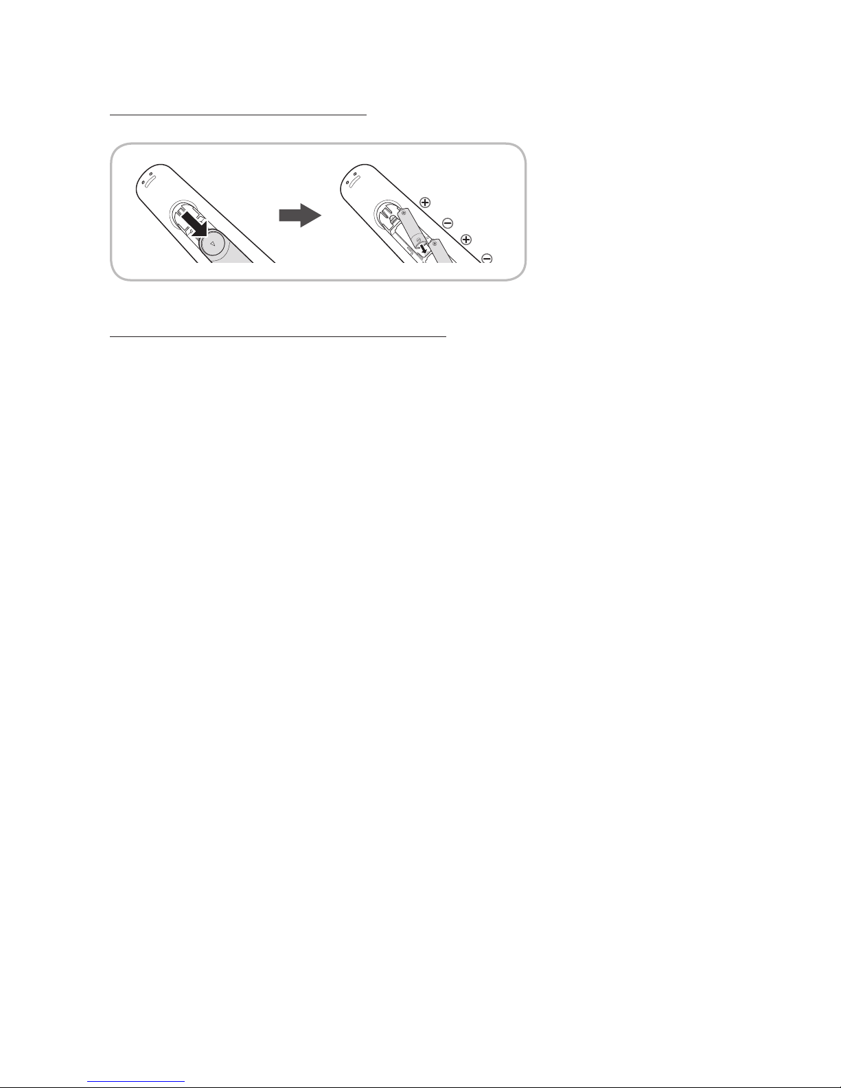
Installing the batteries (Battery size: AAA)
Rear of the Remote
✎ After you have installed the batteries, use a screwdriver to screw in the screw that holds the battery cover closed.
Installing Batteries into the Remote (battery size: AAA)
Match the polarity of the batteries to the symbol in the batter compartment.
✎ NOTE
• Use the remote control within 23~33 feet of the TV.
• Bright light may affect the performance of the remote control. Avoid using near fluorescent lights or neon signs.
• The color and shape of the remote may vary depending on the model.
21
English
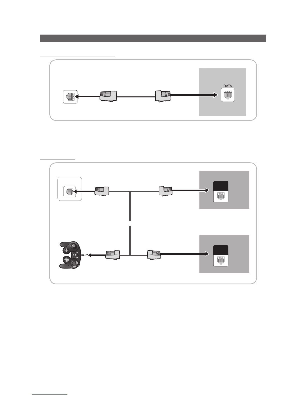
Connecting the TV to the Lodgenet game controller or a STB of a SI vendor
HD470 / HD477 / HD670 / HD677
TV Rear Panel
Data Cable
ETH MODEM
1. Connect the D ATA jack of the TV to the ETH MODEM jack of the STB (SBB) with the Data cable.
✎ The "ETH MODEM" jack name that you connect the Data Cable to may differ depending on the SBB or STB type.
HD478 / HD678
GAME
CONTROL
DATA
ETH MODEM
GAME
CONTROL
DATA
TV Rear Panel
Data Cable
1. Connect the LodgeNet game controller to the TV's GAME CONTROLLER/DATA jack of the TV.
2. Connect the GAME CONTROL DATA jack of the TV to the ETH MODEM jack of the STB (SBB) with the data cable.
✎ The “ETH MODEM” jack name that you connect the Data Cable to may differ depending on the SBB or STB type.
TV Rear Panel
or
Data Cable
Game Controller
22
English
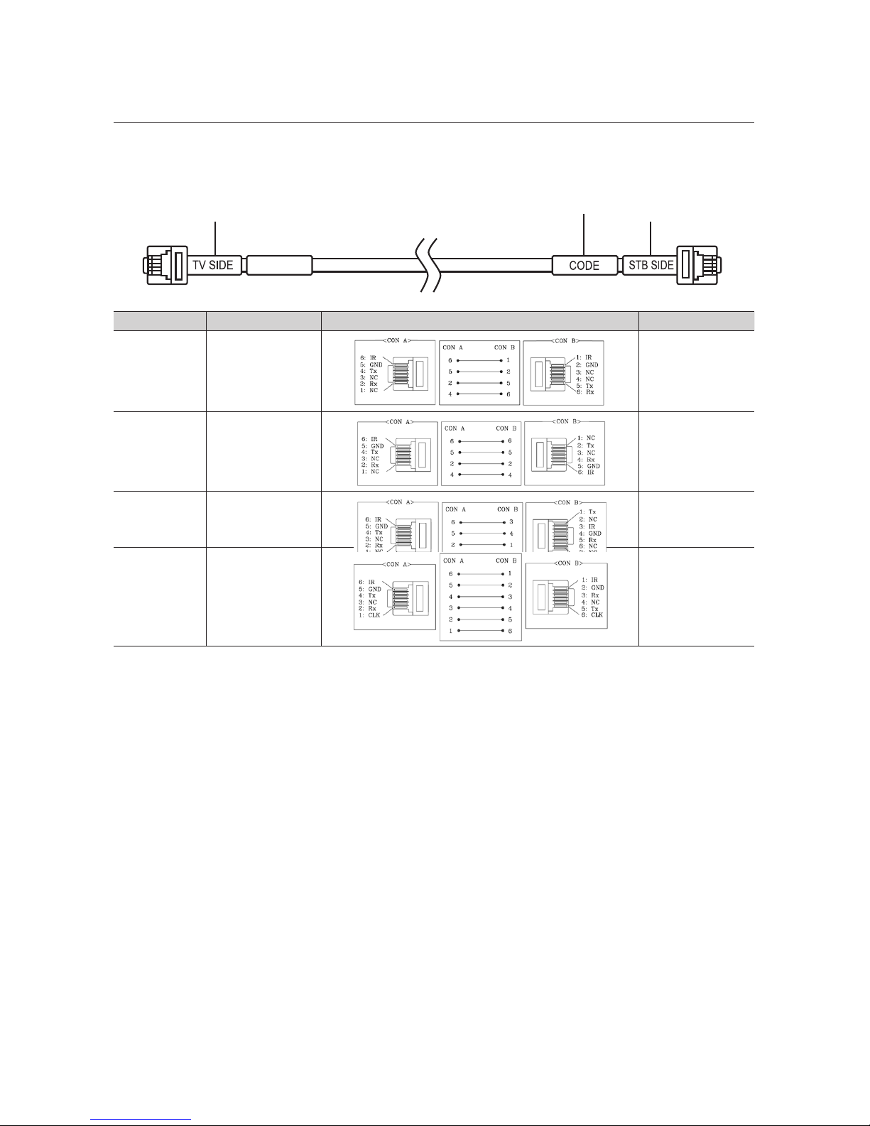
¦ List of SI Vendors and Compatible Data Cables Supplied with the TV
• Confirm you are using the correct data cable for your SI vendor. Refer to the code label on the data cables.
• Contact your nearest dealer or your SI Vendor to buy the data cable not included in the TV.
Confirm the code on
the Code Label
Note the labeled end.
Note the labeled end.
SI Vendor Cable code Pin assign Remark
Samsung
OCC
Enseo
Guest-Tek
BN39-00865B
NXTV BN39-01011B
nStreams BN39-01110A
MTI BN39-01011C
 Loading...