


LCD-Monitor
Chassis LME20WS
LME22WS
Model 206BW
226BW
SERVICEManual
|
|
|
LCD Monitor |
Fashion Feature |
- Magic Bright
- Magic Color
- Integrated UI applied - Hidden Function Key
- Lustrous Appearance (Design)

Copyright
©2006 by Samsung Electronics Co., Ltd. All rights reserved.
This manual may not, in whole or in part, be copied, photocopied, reproduced, translated, or converted to any electronic or machine readable form without prior written permission of Samsung Electronics Co., Ltd.
LME20WS/LME22WS Service Manual
First edition December 2006.
Printed in Korea.
Trademarks
Samsung is the registered trademark of Samsung Electronics Co., Ltd.
LME20WS/LME22WS and MacMaster Cable Adapter are trademarks of Samsung Electronics Co., Ltd.
Macintosh, Power Macintosh are trademarks of Apple Computer, Inc.
All other trademarks are the property of their respective owners.
ii

Contents
1.Precautions………………………………………………………………………………………………………………………………………1-1 1-1 Safety Precautions ……………………………………………………………………………………………………………………… 1-1 1-2 Servicing Precautions …………………………………………………………………………………………………………………… 1-2 1-3 Electrostatically Sensitive Devices (ESD) Precautions ……………………………………………………………………………… 1-2 1-4 Installation Precautions ………………………………………………………………………………………………………………… 1-3
2. Product specifications …………………………………………………………………………………………………………………………2-1
2-1 Fashion Feature…………………………………………………………………………………………………………………………… 2-1
2-2 Feature …………………………………………………………………………………………………………………………………… 2-1
2-3 LME20WS Specifications………………………………………………………………………………………………………………… 2-2
2-4 LME22WS Specifications………………………………………………………………………………………………………………… 2-3
2-5 Spec Comparison ………………………………………………………………………………………………………………………… 2-4
2-6 Option Specification ……………………………………………………………………………………………………………………… 2-5
3. Alignments and Adjustments …………………………………………………………………………………………………………………3-1
3-1 Required Equipment …………………………………………………………………………………………………………………… 3-1 3-2 Automatic Color Adjustment …………………………………………………………………………………………………………… 3-1 3-3 DDC EDID Data Input …………………………………………………………………………………………………………………… 3-1 3-4 Service Function Spec. ………………………………………………………………………………………………………………… 3-2 3-5 Hidden Key list …………………………………………………………………………………………………………………………… 3-3 3-6 EDID Installation with Windows Program ………………………………………………………………………………………………3-4 3-7 Execution Items after replacing the main board ………………………………………………………………………………………3-4
4. Troubleshooting …………………………………………………………………………………………………………………………………4-1
4-1 No Power ……………………………………………………………………………………………………………………………………4-1 4-2 No Video (PC Analog Signal) …………………………………………………………………………………………………………… 4-3 4-3 No Video (PC Digital Signal) …………………………………………………………………………………………………………… 4-5
5. Exploded View and Parts List ………………………………………………………………………………………………………………5-1
6.Electrical Parts List ……………………………………………………………………………………………………………………………6-1
7.Block Diagram …………………………………………………………………………………………………………………………………7-1

Contents
8.Wiring Diagram …………………………………………………………………………………………………………………………………8-1
9.Schematic Diagrams ……………………………………………………………………………………………………………………………9-1 9-1 Schematic Diagrams……………………………………………………………………………………………………………………… 9-1 9-2 Schematic Diagrams ………………………………………………………………………………………………………………………9-3
10. Operating Instructions and Installation ……………………………………………………………………………………………………10-1 10-1 Front …………………………………………………………………………………………………………………………………… 10-1 10-2 Rear ………………………………………………………………………………………………………………………………………10-2 10-3 Using the Stand …………………………………………………………………………………………………………………………10-4
11. Disassembly and Reassembly ………………………………………………………………………………………………………………11-1 11-1 Disassembly …………………………………………………………………………………………………………………………… 11-1 11-2 Reassembly …………………………………………………………………………………………………………………………… 11-3
12. PCB Diagram …………………………………………………………………………………………………………………………………12-1
13.Circuit Descriptions ……………………………………………………………………………………………………………………………13-1 13-1 Block description ……………………………………………………………………………………………………………………… 13-1
13-2 Block operating ……………………………………………………………………………………………………………………… 13-2
14. Reference Infomation ……………………………………………………………………………………………………………………… 14-1
14-1 Technical Terms ……………………………………………………………………………………………………………………… 14-1
14-2 Pin Assignments…………………………………………………………………………………………………………………………14-4
14-3 Timing Chart ……………………………………………………………………………………………………………………………14-5 14-4 Preset Timing Modes ………………………………………………………………………………………………………………… 14-6 14-5 Panel Description ……………………………………………………………………………………………………………………… 14-7
-This Service Manual is a property of Samsung Electronics Co., Ltd.
Any unauthorized use of Manual can be punished under applicable International and/or domestic law.
Samsung Electronics Co.,Ltd.
416, Maetan-3Dong, Yeongtong-Gu, Suwon City, Gyeonggi-Do, Korea, 443-742
Printed in Korea
P/N : BN82-00138M-00
URL : http://itself.sec.samsung.co.kr/
11 Disassembly and Reassembly
11 Disassembly and Reassembly
This section of the service manual describes the disassembly and reassembly procedures for the LHA20WS TFT-LCD monitors.
 WARNING: This monitor contains electrostatically sensitive devices. Use caution when handling these components.
11-1 Disassembly
 Cautions: 1. Disassembly stand on the flat desk.
2. Disconnect the monitor from the power source before disassembly.
Description |
Picture Description |
|
|
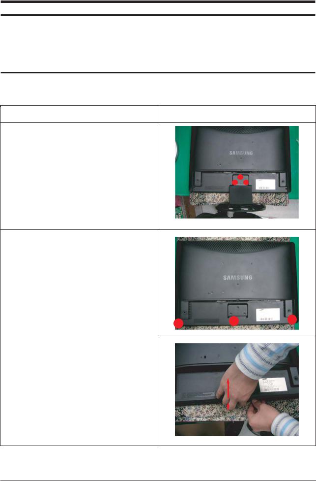
1.Remove 3 screws from the stand and Remove stand.
2.Remove 3 screws from the stand and Lift up back cover.
11-1
11 Disassembly and Reassembly
|
|
|
Description |
|
|
|
Picture Description |
||||||||||||||||||||
|
|
|
|
|
|
|
|
|
|
|
|
|
|
|
|
|
|
|
|
|
|
|
|
|
|
|
|
|
|
|
|
|
|
|
|
|
|
|
|
|
|
|
|
|
|
|
|
|
|
|
|
|
|
|
|
|
|
|
|
|
|
|
|
|
|
|
|
|
|
|
|
|
|
|
|
|
|
|
|
|
|
|
|
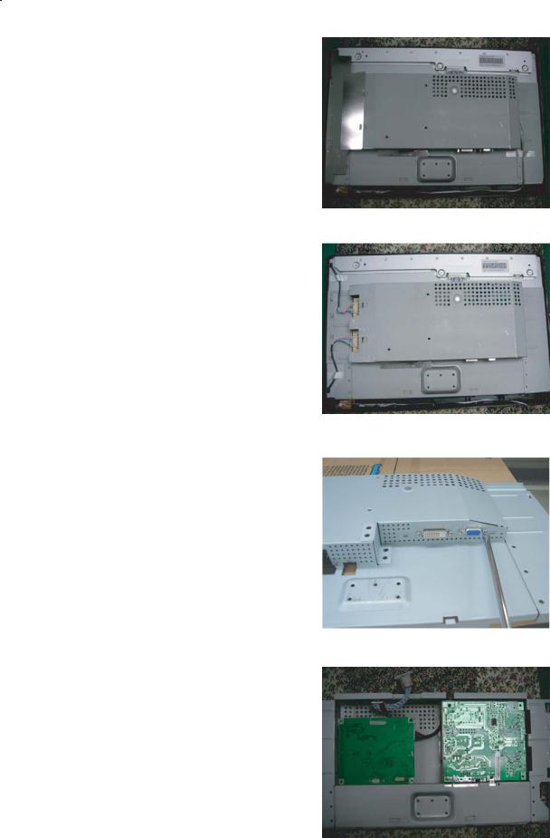
4. |
Use the jig to remove the shield lamp. |
|
|
|
|
|
|
|
|
|
|
|
|
|
|
|
|
|
|
|
|
||||||
|
(Be careful Shield.) |
|
|
|
|
|
|
|
|
|
|
|
|
|
|
|
|
|
|
|
|
|
|
|
|||
|
5. |
Remove the FUNCTION Wire from PCB ASS’Y. |
|
|
|
|
|
|
|
|
|
|
|
|
|
|
|
|
|
|
|
|
|
|
|
||
|
|
|
|
|
|
|
|
|
|
|
|
|
|
|
|
|
|
|
|
|
|
|
|
||||
|
|
|
|
|
|
|
|
|
|
|
|
|
|
|
|
|
|
|
|
|
|
|
|
||||
|
|
|
|
|
|
|
|
|
|
|
|
|
|
|
|
|
|
|
|
|
|
|
|
|
|
|
|
|
|
|
|
|
|
|
|
|
|
|
|
|
|
|
|
|
|
|
|
|
|
|
|
|
|
|
|
|
|
|
|
|
|
|
|
|
|
|
|
|
|
|
|
|
|
|
|
|
|
|
|
|
|
|
|
|
|
|
|
|
|
|
|
|
|
|
|
|
|
|
|
|
|
|
|
|
|
|
|
|
|
|
|
|
|
|
|
|
|
|
|
|
|
|
|
|
|
|
|
|
|
|
|
|
|
|
|
|
|
|
|
|
|
|
|
|
|
|
|
|
|
|
|
|
|
|
|
|
|
|
|
|
|
|
|
|
|
|
|
6. |
Remove the Panel Lamp wire. |
|
|
|
|
|
|
|
|
|
|
|
|
|
|
|
|
|
|
|
|
||||||
|
|
|
|
|
|
|
|
|
|
|
|
|
|
|
|
|
|
|
|
|
|
|
|
|
|
|
|
|
|
|
|
|
|
|
|
|
|
|
|
|
|
|
|
|
|
|
|
|
|
|
|
|
|
|
|
|
|
|
|
|
|
|
|
|
|
|
|
|
|
|
|
|
|
|
|
|
|
|
|
|
|
|
|
|
|
|
|
|
|
|
|
|
|
|
|
|
|
|
|
|
|
|
|
|
|
|
|
|
|||
|
|
7. Remove the LVDS Wire from Panel. |
|
|
|
|
|
|
|
|
|
|
|
|
|
|
|
|
|
|
|
|
|||||
|
|
|
|
|
|
|
|
|
|
|
|
|
|
|
|
|
|
|
|
|
|
|
|
|
|
|
|
|
|
|
|
|
|
|
|
|
|
|
|
|
|
|
|
|
|
|
|
|
|
|
|
|
|
|
|
|
|
|
|
|
|
|
|
|
|
|
|
|
|
|
|
|
|
|
|
|
|
|
|
|
|
|
|
|
|
|
|
|
|
|
|
|
|
|
|
|
|
|
|
|
|
|
|
|
|
|
|
|
|
|
|
|
|
|
|
|
|
|
|
|
|
|
|
|
|
|
|
|
|
|
|
|
|
|
|
|
|
||
8. |
Remove 4 screws. |
|
|
|
|
|
|
|
|
|
|
|
|
|
|
|
|
|
|
|
|
||||||
|
|
|
|
|
|
|
|
|
|
|
|
|
|
|
|
|
|
|
|
|
|
|
|
||||
|
|
|
|
|
|
|
|
|
|
|
|
|
|
|
|
|
|
|
|
|
|
|
|
|
|
|
|
|
|
|
|
|
|
|
|
|
|
|
|
|
|
|
|
|
|
|
|
|
|
|
|
|
|
|
|
|
|
|
|
|
|
|
|
|
|
|
|
|
|
|
|
|
|
|
|
|
|
|
|
|
|
|
|
|
|
|
|
|
|
|
|
|
|
|
|
|
|
|
|
|
|
|
|
|
|
|
|
|
|
|
|
|
|
|
|
|
|
|
|
|
|
|
|
|
|
|
|
|
|
|
|
|
|
|
|
||||
|
|
9. Remove 4 screws and Lift up the Main PCB and |
|
|
|
|
|
|
|
|
|
|
|
|
|
|
|
|
|
|
|
|
|||||
|
|
|
|
|
|
|
|
|
|
|
|
|
|
|
|
|
|
|
|
|
|
|
|
||||
|
|
|
IB Board. |
|
|
|
|
|
|
|
|
|
|
|
|
|
|
|
|
|
|
|
|
|
|||
|
|
|
|
|
|
|
|
|
|
|
|
|
|
|
|
|
|
|
|
|
|
|
|
|
|
|
|
|
|
|
|
|
|
|
|
|
|
|
|
|
|
|
|
|
|
|
|
|
|
|
|
|
|
|
|
|
|
|
|
|
|
|
|
|
|
|
|
|
|
|
|
|
|
|
|
|
|
|
|
|
|
|
|
|
|
|
|
|
|
|
|
|
|
|
|
|
|
|
|
|
|
|
|
|
|
|
|
|
|
|
|
|
|
|
|
|
|
|
|
|
|
|
|
|
|
|
|
|
|
|
|
|
|
|
|
|
|
|
|
|
|
|
|
|
|
|
|
|
|
|
|
|
|
|
|
|
|
|
|
|
|
|
|
|
|
|
|
|
|
|
|
|
|
|
|
|
|
|
|
|
|
|
|
|
|
|
|
|
|
|
|
|
|
|
|
|
|
|
|
|
|
|
|
|
|
|
|
|
|
|
|
|
|
|
|
|
|
|
|
|
|
|
|
|
|
|
|
|
|
|
|
|
|
|
|
|
|
|
|
|
|
|
|
|
|
|
|
|
|
|
|
11-2
11 Disassembly and Reassembly
Description |
Picture Description |
|
|
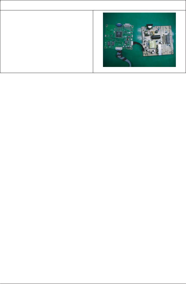
10. Main PCB and IB Board
11-3

11 Disassembly and Reassembly
11-2 Reassembly
Reassembly procedures are in the reverse order of disassembly procedures.
11-4
12 PCB Daigram
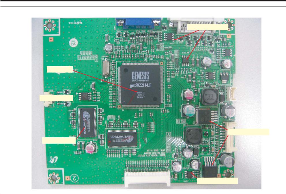
12 PCB Diagram
12-1 Main PCB
EEPROM
scaler
Flash memory 
EEPROM
SDRAM Memory
FET Array
12-1
12 PCB Diagram
Memo
12-2

13 Circuit Descriptions
13 Circuit Descriptions
13-1 Block description
EEPROM |
EEPROM |
FET Array
scaler
Flash memory
SDRAM Memory
13-1

13 Circuit Descriptions
Memo
13-2

14 Reference Infomation
14 Reference Infomation
14-1 Technical Terms
- TFT-LCD
(Thin film Transistor Liquid Crystal Display)
ADC(Analog to Digital Converter)
This is a circuit that converts from analog signal to digital signals.
- PLL(Phase Locked Loop)
During progressing ADC, Device makes clock synchronizing HSYNC with Video clock
- Inverter
Device that supplies Power to LCD panel lamp. This device generates about 1,500~2,000V.
- SMPS(Switching Mode Power Supply)
- FINE
"Fine" adjustment is used to adjust visibility by control phase difference.
- COARSE
This is a adjustment by tuning with Video colck and PLL clock.
- DVI (Digital Visual Interface)
This provides a high speed digital connection for visual data types that is display technology independent. this interface is primarily forcused at providing a connection between a computer and its display device.
Switching Mode Power supply. This design technology is used to step up/down the input power by switching on/off
- FRC(Frame Rate Controller)
Technology that change image frame quantity displayed on screen for one second.
Actually TFT-LCD panel require 60 pcs of frame for one second.
so,this technology is needed to convert input image to 60 pcs regardless input frame quantity.
-L.V.D.S.(Low Voltage Differential Signaling) a kind of transmission method for Digital.
It can be used from Main PBA to Panel.
-DVI (Digital Visual Interface)
This provides a high speed digital connection for visual data types that is display technology independent. this interface is primarily forcused at providing a connection between a computer and its display device.
- T.M.D.S
- Image Scaler
Technology that convert various input resolution to other resolution.(ex. 640* 480 to 1024*768)
- Auto Configuration(Auto adjustment)
This is an algorithm to adjust monitor to optimum condition by pushing one key.
- OSD(On Screen Display)
On screen display. customer can control the screen easily with this.
- Image Lock
This means "Fineness adjustment" in LCD Monitor, the features are "Fine" and "Coarse"
(Transition minimized Differential Signaling) a kind of transmission method for Digital.
It can be used from Video card to Main PBA.
- DDC(Display data channel)
It is a communication method between Host Computer and related equipment.
It can make it Plug and Play between PC and Monitor.
- EDID
Extended Display Identification Data PC can recognize the monitor information as Product data, Product name,Display mode,Serial number and Signal source,etc through DDC Line communicating with PC and Monitor.
14-1

14 Reference Infomation
- Dot Pitch
The image on a monitor is composed of red, green and blue dots. The closer the dots, the higher the resolution. The distance between two dots of the same color is called the 'Dot Pitch'. Unit: mm
- Vertical Frequency
The screen must be redrawn several times per second in order to create and display an image for the user. The frequency of this repetition per second is called Vertical Frequency or Refresh Rate. Unit: Hz
Example: If the same light repeats itself 60 times per second, this is regarded as 60 Hz.
- Horizontal Frequency
The time to scan one line connecting the right edge to the left edge of the screen horizontally is called Horizontal Cycle. The inverse number of the Horizontal Cycle is called Horizontal Frequency. Unit: kHz
- Interlace and Non-Interlace Methods
Showing the horizontal lines of the screen from the top to the bottom in order is called the Non-Interlace method while showing odd lines and then even lines in turn is called the Interlace method. The Non-Interlace method is used for the majority of monitors to ensure a clear image. The Interlace method is the same as that used in TVs.
- Plug & Play
This is a function that provides the best quality screen for the user by allowing the computer and the monitor to exchange information automatically. This monitor follows the international standard VESA DDC for the Plug & Play function.
- Resolution
The number of horizontal and vertical dots used to compose the screen image is called 'resolution'. This number shows the accuracy of the display. High resolution is good for performing multiple tasks as more image information can be shown on the screen.
Example: If the resolution is 1280 x 1024 , this means the screen is composed of 1280 horizontal dots (horizontal resolution) and 1024 vertical lines (vertical resolution).
- S-Video
Short for "Super Video." S-Video allows up to 800 lines of horizontal resolution, enabling high-quality video.
- External Device Input
External device input refers to video input from such external video devices as VCRs, camcorders and DVD players, separate from a TV broadcast.
- DVD
A type of digital disk technology that takes up only the benefits of CD and LD, to implement a high resolution/quality, which enables the user to enjoy clearer images.
14-2
14 Reference Infomation
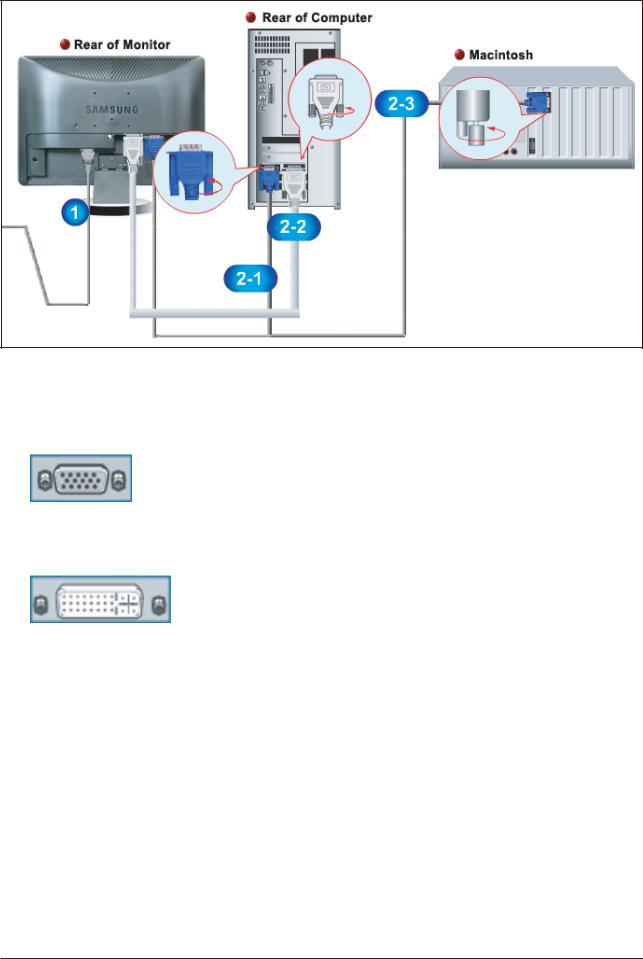
- Connecting the Monitor
1.Connect the DC adapter for your monitor to the power port on the back of the monitor. Plug the power cord for the monitor into a nearby outlet.
2-1. Using the D-sub (Analog) connector on the video card.
Connect the signal cable to the 15-pin, D-sub connector on the back of your monitor.
2-2. Using the DVI (Digital) connector on the video card.
Connect the DVI cable to the DVI port on the back of your monitor.
2-3. Connected to a Macintosh.
Connect the monitor to the Macintosh computer using the D-SUB connection cable.
3.Turn on your computer and monitor. If your monitor displays an image, installation is complete.
-You may get a blank screen depending on the type of video card you are using, if you connect simultaneously both the D-Sub and DVI cables to one computer.
-If you properly connect your monitor using the DVI connector but get a blank screen, check to see if the monitor status is set to analog. Press power button to have the monitor double-check the input signal source.
14-3
14 Reference Infomation
14-2 Pin Assignments |
|
|
|
|
Sync |
|
15-Pin D-Sub Signal Cable Connector |
||
Type |
Separate |
|
Composite |
Sync-on-green |
Pin No. |
|
|||
|
|
|
|
|
1 |
Red |
|
Red |
Red |
2 |
Green |
|
Green |
Green + H/V Sync. |
3 |
Blue |
|
Blue |
Blue |
4 |
GND |
|
GND |
GND |
5 |
DDC Return (GND) |
|
DDC Return (GND) |
DDC Return (GND) |
6 |
GND-R |
|
GND-R |
GND-R |
7 |
GND-G |
|
GND-G |
GND-G |
8 |
GND-B |
|
GND-B |
GND-B |
9 |
DDC Power Input (+5V) |
DDC Power Input (+5V) |
DDC Power Input (+5V) |
|
10 |
Self Raster |
|
Self Raster |
Self Raster |
11 |
GND |
|
GND |
GND |
12 |
Bi-Dr Data (SDA) |
|
Bi-Dr Data (SDA) |
Bi-Dr Data (SDA) |
13 |
H-Sync. |
|
H/V-Sync. |
Not Used |
14 |
V-Sync. |
|
Not Used |
Not Used |
15 |
DDC Clock (SCL) |
|
DDC Clock (SCL) |
DDC Clock (SCL) |
Sync |
|
|
|
|
Type |
|
24P DVI-D |
|
Pin No. |
|
|
|
1 |
Rx2- |
13 |
No Connection |
2 |
Rx2+ |
14 |
+5V_M |
3 |
GND |
15 |
Self Raster |
4 |
No Connection |
16 |
+5V_M |
5 |
No Connection |
17 |
Rx0- |
6 |
DDC Clock (SCL) |
18 |
Rx0+ |
7 |
DDC Data (SDA) |
19 |
NC |
8 |
NC |
20 |
No Connection |
9 |
Rx1- |
21 |
No Connection |
10 |
Rx1+ |
22 |
NC |
11 |
NC |
23 |
RxC+ |
12 |
No Connection |
24 |
RxC- |
|
|
|
|
14-4
14 Reference Infomation
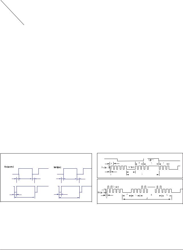
14-3 Timing Chart
- This section of the service manual describes the timing that the computer industry recognizes as standard for computer-generated video signals.
Table 14-1 Timing Chart
Mode |
IBM |
|
|
|
VESA |
|
|
|
|
|
|
|
|
|
|
|
|
|
|
|
VGA2/ |
VGA3/ |
640/75 Hz |
800/60 Hz |
800/75 Hz |
1024/60 Hz |
1024/75 Hz |
1280/60 Hz |
1280/75 Hz |
|
70 Hz |
60 Hz |
|||||||
|
640x480 |
800x600 |
800x600 |
1024x768 |
1024x768 |
1280x1024 |
1280x1024 |
||
Timing |
720 x 400 |
640 x 480 |
|||||||
|
|
|
|
|
|
|
|
|
|
fH (kHz) |
31.469 |
31.469 |
37.500 |
37.879 |
46.875 |
48.363 |
60.023 |
63.981 |
79.975 |
A μsec |
31.777 |
31.778 |
26.667 |
26.400 |
21.333 |
20.677 |
16.660 |
11.852 |
12.504 |
B μsec |
3.813 |
3.813 |
2.032 |
3.200 |
1.616 |
2.092 |
1.219 |
1.037 |
1.067 |
C μsec |
1.589 |
1.589 |
3.810 |
2.200 |
3.232 |
2.462 |
2.235 |
2.296 |
1.837 |
D μsec |
26.058 |
26.058 |
20.317 |
20.000 |
16.162 |
15.754 |
13.003 |
9.259 |
9.481 |
E μsec |
0.318 |
0.318 |
0.508 |
0.000 |
0.323 |
0.369 |
0.203 |
0.000 |
0.119 |
fV (Hz) |
70.087 |
59.940 |
75.000 |
60.317 |
75.000 |
60.004 |
75.029 |
60.020 |
75.025 |
|
|
|
|
|
|
|
|
|
|
O msec |
14.268 |
16.683 |
13.333 |
16.579 |
13.333 |
16.666 |
13.328 |
16.005 |
13.329 |
P msec |
0.064 |
0.064 |
0.080 |
0.106 |
0.064 |
0.124 |
0.050 |
0.047 |
0.038 |
Q msec |
0.858 |
0.794 |
0.427 |
0.607 |
0.448 |
0.600 |
0.466 |
0.594 |
0.475 |
R msec |
13.155 |
15.761 |
12.800 |
15.840 |
12.800 |
15.880 |
12.795 |
15.630 |
12.804 |
S msec |
0.191 |
0.064 |
0.027 |
0.0261 |
0.021 |
0.062 |
0.017 |
0.016 |
0.013 |
Clock |
|
|
|
|
|
|
|
|
|
Freq. |
28.322 |
26.175 |
31.500 |
40.000 |
49.500 |
75.000 |
78.750 |
108.000 |
135.000 |
(MHz) |
|
|
|
|
|
|
|
|
|
Polarity |
|
|
|
|
|
|
|
|
|
H.Sync |
Negative |
Negative |
Negative |
Positive |
Positive |
Negative |
Positive |
Positive |
Positive |
V.Sync |
Positive |
Negative |
Negative |
Positive |
Positive |
Negative |
Positive |
Positive |
Positive |
Remark |
Separate |
Separate |
Separate |
Separate |
Separate |
Separate |
Separate |
Separate |
Separate |
|
|
|
|
|
|
|
|
|
|
|
|
Separate Sync |
|
|
|
Video |
|
|
Video |
|
|
C |
D |
E |
Q |
R |
S |
Sync |
|
|
Sync |
|
|
|
B |
|
|
P |
|
|
A |
|
|
O |
|
H/V Composite Sync |
Sync-on-Green |
A : Line time total |
B : Horizontal sync width |
O : Frame time total |
P : Vertical sync width |
C : Back porch |
D : Active time |
Q : Back porch |
R : Active time |
E : Front porch |
|
S : Front porch |
|
|
|
|
|
14-5

14 Reference Infomation
14-4 Preset Timing Modes
- If the signal transferred from the computer is the same as the following Preset Timing Modes, the screen will be adjusted automatically. However, if the signal differs, the screen may go blank while the power LED is on. Refer to the video card manual and adjust the screen as follows.
Table 1. Preset Timing
Display Mode |
Horizontal |
Vertical Frequency |
Pixel Clock |
Sync Polarity |
|
Frequency |
|||||
(Hz) |
(MHz) |
(H/V) |
|||
|
(kHz) |
||||
|
|
|
|
||
|
|
|
|
|
|
MAC, 640 x 480 |
35.000 |
66.667 |
30.240 |
-/- |
|
|
|
|
|
|
|
MAC, 832 x 624 |
49.726 |
74.551 |
57.284 |
-/- |
|
|
|
|
|
|
|
IBM, 640 x 350 |
31.469 |
70.086 |
25.175 |
+/- |
|
|
|
|
|
|
|
IBM, 640 x 480 |
31.469 |
59.940 |
25.175 |
-/- |
|
|
|
|
|
|
|
IBM, 720 x 400 |
31.469 |
70.087 |
28.322 |
-/+ |
|
|
|
|
|
|
|
VESA, 640 x 480 |
37.500 |
75.000 |
31.500 |
-/- |
|
|
|
|
|
|
|
VESA, 640 x 480 |
37.861 |
72.809 |
31.500 |
-/- |
|
|
|
|
|
|
|
VESA, 800 x 600 |
35.156 |
56.250 |
36.000 |
+,-/+,- |
|
|
|
|
|
|
|
VESA, 800 x 600 |
37.879 |
60.317 |
40.000 |
+/+ |
|
|
|
|
|
|
|
VESA, 800 x 600 |
46.875 |
75.000 |
49.500 |
+/+ |
|
|
|
|
|
|
|
VESA, 800 x 600 |
48.077 |
72.188 |
50.000 |
+/+ |
|
|
|
|
|
|
|
VESA, 1024 x 768 |
48.363 |
60.004 |
65.000 |
-/- |
|
|
|
|
|
|
|
VESA, 1024 x 768 |
56.476 |
70.069 |
75.000 |
-/- |
|
|
|
|
|
|
|
VESA, 1024 x 768 |
60.023 |
75.029 |
78.750 |
+/+ |
|
|
|
|
|
|
|
VESA, 1280 x 1024 |
63.981 |
60.020 |
108.00 |
+/+ |
|
|
|
|
|
|
|
VESA, 1280 x 1024 |
79,976 |
75,025 |
135,00 |
+/+ |
|
|
|
|
|
|
|
VESA, 1600 x 1200 |
75.000 |
60.000 |
162.00 |
+/+ |
|
|
|
|
|
|
Horizontal Frequency
The time to scan one line connecting the right edge to the left edge of the screen horizontally is called Horizontal Cycle and the inverse number of the Horizontal Cycle is called Horizontal Frequency. Unit: kHz
Vertical Frequency
Like a fluorescent lamp, the screen has to repeat the same image many times per second to display an image to the user. The frequency of this repetition is called Vertical Frequency or Refresh Rate. Unit: Hz
14-6

14 Reference Infomation
14-5 Panel Description
Maker |
VENDOR P/N |
PANEL_CODE |
PANEL_ABB |
STICKER_CODE |
Remarks |
|
|
|
|
|
|
SEC |
LT140X1-002 |
BN07-00004A |
SA |
BN68-00239H |
- |
SEC |
LT150XS-L01 |
BN07-00009A |
SB |
|
- |
SEC |
LT150XS-L01-B |
BN07-00022A |
SC |
|
- |
SEC |
LTM150XS-L02 |
BN07-00005A |
SD |
|
- |
SEC |
LT181E2-132 |
BN07-00001A |
SE |
|
- |
SEC |
LT150XS-T01 |
BN07-00010A |
SF |
|
- |
SEC |
LTM181E3-132 |
BN07-00019A |
SG |
|
- |
SEC |
LT170E2-131 |
BN07-10001D |
SH |
|
- |
SEC |
LT181E2-131 |
BN07-10001E |
SJ |
|
- |
SEC |
LTM170E4-L01 |
BN07-00018A |
SK |
|
- |
SEC |
LTM240W1-L01 |
BN07-00015A |
SL |
|
- |
SEC |
LTM213U3-L01 |
BN07-00016A |
SM |
|
- |
SEC |
LTM150XH-L01 |
BN07-00026A |
SN |
|
|
SEC |
LTM150XH-L03 |
BN07-00027A |
SP |
|
- |
SEC |
LTM150XS-L01 |
BN07-00032A |
SQ |
|
DELL(ZPD) |
SEC |
LTM181E4-L01 |
BN07-00034A |
SR |
|
PVA |
SEC |
LTM170EH-L01 |
BN07-00036A |
SS |
|
TN |
SEC |
LTM170E5-L01 |
BN07-00037A |
SU |
|
PVA |
SEC |
LTM150XH-L11 |
BN07-00041A |
SV |
|
- |
SEC |
LTM213U4-L01 |
BN07-00039A |
SW |
|
PVA |
SEC |
LTM150XH-L01(ZPD) |
BN07-00045A |
SX |
|
ZPD |
SEC |
LTM150XH-L04 |
BN07-00046A |
SY |
|
New panel with high brightness |
SEC |
LTM170W1-L01 |
BN07-00047A |
SZ |
|
Panel for TV |
SEC |
LTM150XH-L06 |
BN07-00053A |
EA |
|
Panel for TV/ High luminance for 450cd _ SONY&EOS Team Panel for TV |
SEC |
LTM153W1-L01 |
BN07-00054A |
EB |
|
Use NIKE MODEL |
SEC |
LTM170EH-L05 |
BN07-00055A |
EC |
|
Panel EOS proj. for high brightness of 17" EH-L05 |
SEC |
LTM170E5-L03 |
BN07-00056A |
ED |
|
Dell 1702FP pro. E4. EH mechanical Compatible |
SEC |
LTM190E1-L01 |
BN07-00057A |
EE |
|
DELL 1900 FP |
SEC |
LTM181E5-L01 |
BN07-00061A |
EF |
|
18" narrow bezel GH18PS |
SEC |
LTM150XP-L01 |
BN07-00065A |
EG |
|
AMLCD PVA PANEL |
SEC |
LTM240W1-L02 |
BN07-00062A |
EH |
|
Panel for 15" Wide TV |
SEC |
LTM170EU-L01 |
BN07-00071A |
EJ |
|
Slim design, TN |
SEC |
LTM170E5-L04 |
BN07-00072A |
EK |
|
E5-L04 6 bits FRC... for IBM |
SEC |
LTA220W1-L01 |
BN07-00074A |
EL |
|
Panel for 22" TV |
SEC |
LTM170E6-L02 |
BN07-00075A |
EM |
|
AMLCD Narrow & slim design 17" PVA mode |
SEC |
LTM170W1-L01 |
BN07-00082A |
EN |
|
LTM170W1-L01 ZPD panel |
SEC |
LTM170EH-L01 |
BN07-00080A |
EP |
|
LTM170EH-L01 ZPD panel |
SEC |
LTM170E5-L01 |
BN07-00081A |
EQ |
|
LTM170E5-L01 ZPD panel |
SEC |
LTM170EH-L05 |
BN07-00083A |
ER |
|
LTM170EH-L05 ZPD panel |
SEC |
LTM170E5-L03 |
BN07-00084A |
ES |
|
LTM170E5-L03 ZPD panel |
SEC |
LTM170EU-L01 |
BN07-00085A |
ET |
|
LTM170EU-L01 ZPD panel |
SEC |
LTM170E5-L04 |
BN07-00086A |
EU |
|
LTM170E5-L04 ZPD panel |
SEC |
LTM170E6-L02 |
BN07-00087A |
EV |
|
LTM170E6-L02 ZPD panel |
SEC |
LTM150XH-L06 |
BN07-00091A |
EW |
|
Color coordinates change for LCD TV |
SEC |
LTM153W1-L01 |
BN07-00092A |
EX |
|
AMLCD WIDE 15",9/10 |
SEC |
LTM170W1-L01 |
BN07-00100A |
EY |
|
Color Coordinates change code management |
SEC |
LTM170EH-L05 |
BN07-00097A |
EZ |
|
LTM170E5-L05 Color Coordinates Change Panel Code |
SEC |
LTA400W1-L01 |
BN07-00109A |
S1 |
|
PANEL of AMLCD 40" TV |
SEC |
LTM153W1-L01 |
BN07-00110A |
S2 |
|
Color coordinates change 0.280/0.290, 10000k & ZPD Panel |
SEC |
LTM150XH-L06 |
BN07-00111A |
S3 |
|
Color coordinates change 0.280/0.290, 10000k & ZPD Panel |
SEC |
LTM170W1-L01 |
BN07-00112A |
S4 |
|
Color coordinates change 0.280/0.290, 10000k & ZPD Panel |
SEC |
LTM170EH-L05 |
BN07-00113A |
S5 |
|
Color coordinates change 0.280/0.290, 10000k & ZPD Panel |
SEC |
LTM220W1-L01 |
BN07-00114A |
S6 |
|
ZPD Panel for AMLCD 22" TV |
SEC |
LTM150XH-L06 |
BN07-00117A |
S7 |
|
ZPD Panel code |
SEC |
LTM153W1-L01 |
BN07-00118A |
S8 |
|
ZPD Panel code |
SEC |
LTM170WP-L01 |
BN07-00119A |
S9 |
|
PVA Panel for NIKE |
SEC |
LTM213U4-L01 |
BN07-00039A |
E1 |
|
21.3" NARROW |
SEC |
LTA260W1-L01 |
BN07-00121A |
E2 |
|
VENUS |
SEC |
LTA220W1-L01 |
BN07-00074B |
E3 |
|
"Panel B-level panel code for 22"" TV Panel " |
SEC |
LTA320W1-L01 |
BN07-00108A |
E4 |
|
"Panel for AMLCD 32"" TV" |
SEC |
LTM213U4-L01 |
BN07-00124A |
E5 |
|
NARROW BEZEL 21 " PANEL |
SEC |
LTM170E6-L04 |
BN07-00129A |
E6 |
|
"HIGHLAND 17"" LOW PANEL (Panel only for TCO03)" |
SEC |
LTM190E1-L01 |
BN07-00088A |
E7 |
|
LTM190E1-L01 ZPD panel |
SEC |
M150X4-L06 |
BN07-00137A |
E8 |
|
15" Narrow & Slim panel |
SEC |
LTA170V1 |
BN07-00139A |
E9 |
|
"17"" Panel for Muse 4:3 VGA TV" |
SEC |
LTM190E1-L02 |
BN07-00128A |
E10 |
|
"New Panel from AMLCDl, Specification : 6bit Driver IC" |
SEC |
LTM170EX-L01 |
BN07-00143A |
E11 |
|
"Development new Panel from AMLCD" |
SEC |
LTM170E8-L01 |
BN07-00144A |
E12 |
|
"Development new Panel from AMLCD" |
SEC |
LTM170E6-L04 |
BN07-00129B |
E13 |
|
"ZPD panel for AMLCD (Panel only for TCO03)" |
SEC |
LTA320W1-L02 |
BN07-00108B |
E14 |
|
"Creat B-level Panel code for AMLCD 32"" TV" |
SEC |
LTM190E1-L03 |
BN07-00151A |
E15 |
|
"Development new 19"" Panel form AMLCD (Panel only for TCO03)" |
SEC |
LTM240W1-L03 |
BN07-00134A |
E16 |
|
"AMLCD 24"" panel development" |
SEC |
LTM190E1-L02 |
BN07-00128B |
E17 |
|
"New Panel from AMLCD, Specification : 6bit Driver IC(ZPD)" |
SEC |
LTM190E4-L01 |
BN07-00145A |
E18 |
|
"AMLCD 24"" new panel development" |
SEC |
LTM170E8-L01 |
BN07-00158A |
E19 |
|
"ZPD code derivation" |
SEC |
LTM170EX-L01 |
BN07-00159A |
E20 |
|
"ZPD code derivation" |
SEC |
LTM190E1-L03 |
BN07-00151B |
E21 |
|
"Creat new panel code for AMLCD 19"" (Panel only for TCO03)" |
|
|
|
|
|
|
14-7
14 Reference Infomation
Maker |
VENDOR P/N |
PANEL_CODE |
PANEL_ABB |
STICKER_CODE |
Remarks |
|
|
|
|
|
|
SEC |
LTA460H1-L01 |
BN07-00157A |
E22 |
|
"creat panel code for AMLCD 46"" TV " |
SEC |
LTM170EU-L11 |
BN07-00160A |
E23 |
|
"creat new panel code for AMLCD 17"" (Panel only for TCO03)" |
SEC |
LTM240W1-L03 |
BN07-00134B |
E24 |
|
"24"" panel ZPD code derivation" |
SEC |
LTM190E4-L01 |
BN07-00145B |
E25 |
|
"AMLCD 19"" ZPD Panel code derivation" |
SEC |
LTM240W1-L03 |
BN07-00134B |
E26 |
|
"24"" panel ZPD code derivation" |
SEC |
LTM150XO-L01 |
BN07-00164A |
E27 |
|
"AMLCD 15"" XO-L01 new panel development" |
SEC |
LTM150XO-L01 |
BN07-00164B |
E28 |
|
"AMLCD 15"" XO-L01 ZPD code derivation" |
SEC |
LTM170EU-L11 |
BN07-00160B |
E29 |
|
"AMLCD 17"" NEW panel code derivation" |
SEC |
LTA320W2-L01 |
BN07-00172A |
SPZ |
|
AMLCD 32" NEW panel |
SEC |
LTM213U4-L01 |
BN07-00124B |
SPZ |
|
21.3" Narrow PANEL ZPD Panel derivation |
SEC |
LTM170EU-L11 |
BN07-00189A |
STH |
|
AMLCD EU-L11 Pb free panel code derivation |
SEC |
LTM170EU-L11 |
BN07-00189B |
STZ |
|
AMLCD EU-L11 Pb free panel ZPD code derivation |
SEC |
LTM240W1-L04 |
BN07-00188A |
SPH |
|
24" A-DCC new panel development |
SEC |
LTM240W1-L04 |
BN07-00188B |
SPZ |
|
24" A-DCC panel ZPD code derivation |
SEC |
LTM190EX-L01 |
BN07-00191A |
STH |
|
AMLCD 19" TN new Panel |
SEC |
LTM190EX-L02 |
BN07-00191B |
STZ |
|
AMLCD 19" TN new Panel ZPD derivation |
SEC |
LTA230W1-L02 |
BN07-00184A |
SPZ |
|
AMLCD 23" 16:9 new Panel |
SEC |
LTA260W2-L01 |
BN07-00185A |
SPZ |
|
AMLCD 26" 16:9 new Panel |
SEC |
LTM240M1-L01 |
BN07-00195A |
SPH |
|
24" panel with high brightness deveiopment |
SEC |
LTA400W2-L01 |
BN07-00186A |
SPZ |
|
AMLCD 40" 16:9 new Panel |
SEC |
LTM150XO-L01 |
BN07-00197A |
STH |
|
AMLCD 15" XO-L01 Pb free panel code |
SEC |
LTM150XO-L01 |
BN07-00197B |
STZ |
|
AMLCD 15" XO-L01 Pb free panel ZPD code |
SEC |
LTM170EU-L21 |
BN07-00202A |
STZ |
|
AMLCD EU-L21 ZPD new code derivation |
SEC |
LTA460W2-L03 |
BN07-00187A |
SPZ |
|
BEETOVEN 46"ZPD new panel |
SEC |
LTM240M1-L01 |
BN07-00195B |
SPZ |
|
24" igh brightness panel ZPD code derivation |
SEC |
M170EX-L21 |
BN07-00206A |
STZ |
|
AMLCD LTM170EX-L21 ZPD new code derivation |
SEC |
LTA460H3-L01 |
BN07-00200A |
SPZ |
|
AMLCD 46" LED BLU panel |
SEC |
LTM170EU-L15 |
BN07-00214A |
STZ |
|
AMLCD EU-L15 TV high brightness ZPD new code derivation |
SEC |
LTM170E8-L21 |
BN07-00218A |
SPZ |
|
AMLCD LTM170E8-L21 PVA ZPD new code derivation |
SEC |
LTM190EX-L21 |
BN07-00222A |
STZ |
|
DISPLAY LCD |
SEC |
LTM201U1-L01 |
BN07-00190B |
SPZ |
|
AMLCD 20.1" Normal panel ZPD code derivation |
SEC |
LTM190E4-L21 |
BN07-00223A |
SPZ |
|
HAYDN 17" PZD code PANEL derivation |
SEC |
LTA570H1-L01 |
BN07-00196A |
SPZ |
|
AMLCD 57" new panel development |
SEC |
LTM150XO-L21 |
BN07-00229A |
STZ |
|
AMLCD 15" XO-L21 8ms panel code |
SEC |
LTA260W2-L11 |
BN07-00239A |
SPZ |
|
AMLCD 26" 16:9 7Line new Panel |
SEC |
LTA400WS-LH1 |
BN07-00245A |
SPZ |
|
AMLCD 40" 16:9 SPVA 90% new Panel |
SEC |
LTM213U6-L01 |
BN07-00231A |
SPZ |
|
AMLCD 21.3" PVA new Panel Code |
SEC |
LTA320WS-LH2 |
BN07-00244A |
SPZ |
|
AMLCD 32" 16:9 SPVA 90% new Panel |
SEC |
LTA400WS-LH1 |
BN07-00245A |
SPZ |
|
AMLCD 40" 16:9 SPVA 90% new Panel |
CPT |
CLAA150XG09 |
BN07-00141A |
PA |
|
"CPT 15"" Monitor new panel development" |
CPT |
CLAA170EA02 |
BN07-00148A |
PB |
|
"17"" CPT NEW development panel" |
CPT |
CLAA170EA02 |
BN07-00148B |
PC |
|
"17"" CPT ZPD panel code derivation" |
CPT |
CLAA150XG09 |
BN07-00141B |
PTZ |
|
"CPT 15"" panel ZPD code derivation (GOYA-PJT)" |
CPT |
CLAA150XP01 |
BN07-00173A |
PTH |
|
CPT 15" PSWG code derivation |
CPT |
CLAA150XP01 |
BN07-00173B |
PTZ |
|
CPT 15" PSWG panel ZPD code |
CPT |
CLAA170EA07 |
BN07-00174A |
PTH |
|
"CPT 17"" PSWG panel code derivation |
CPT |
CLAA170EA07 |
BN07-00174B |
PTZ |
|
CPT 17"""" PSWG type new Panel code""" |
CPT |
CLAA170EA07 |
BN07-00174B |
PTZ |
|
CPT 17" PSWG type new Panel code |
CPT |
CLAA170EA07Q |
BN07-00220A |
PTZ |
|
CPT 17" PSWG R/T 8msec code derivation |
CPT |
CLAA170EA07Q |
BN07-00220B |
PTH |
|
CPT 17" PSWG R/T 8msec HPD code derivation |
CPT |
CLAA150XP01F |
BN07-00236A |
PTZ |
|
CPT 15" PSWG panel ZPD & Lead free code derivation |
TOSHIBA |
LTM15C419(A) |
BN07-00002A |
TA |
|
- |
TOSHIBA |
LTM15C423(B) |
BN07-00006A |
TB |
|
- |
TOSHIBA |
LTM18C161 |
BN07-00008A |
TC |
|
- |
TOSHIBA |
LTM15C443 |
BN07-00031A |
TD |
|
- |
TOSHIBA |
LTM15C458 |
BN07-00043A |
TE |
|
- |
TOSHIBA |
LTM15C458S |
BN07-00077A |
TF |
|
"TSB 15"" high brightness Panel" |
TOSHIBA |
LTM15C458 |
BN07-00078A |
TG |
|
Toshiba ZPD panel |
TOSHIBA |
LTM15C458S |
BN07-00099A |
TH |
|
TSB LTM15C458S ( ZPD ) |
HANNSTAR |
HSD150MX41A(A) |
BN07-00020A |
NA |
|
"TTL type" |
HANNSTAR |
HSD150MX12 |
BN07-00030A |
NB |
|
"TTL type" |
HANNSTAR |
HSD170ME13 |
BN07-00180A |
NTH |
|
Hannstar 17" TN new panel development |
HANNSTAR |
HSD170ME13 |
BN07-00180B |
NTZ |
|
Hannstar 17" TN new panel development ZPD code derivation |
HANNSTAR |
HSD190ME12 |
BN07-00210A |
NTZ |
|
Hannstar 19" TN new panel development |
HANNSTAR |
HSD150MX17-A |
BN07-00226A |
NTZ |
|
Hannstar 15" slim panel ZPD code derivation |
TORISAN |
TM150XG-22L03(A) |
BN07-00021A |
RA |
|
- |
TORISAN |
TM150XG-26L06 |
BN07-00042A |
RB |
|
- |
TORISAN |
TM181SX-76N01 |
BN07-00048A |
RC |
|
- |
TORISAN |
TM150XG-26L06 |
BN07-00059A |
RD |
|
15" XGA TN MODE(ZPD) |
TORISAN |
TM290WX-71N31 |
BN07-00063A |
RE |
|
"RS24NS (TORISAN 29"" NEW PANEL)" |
TORISAN |
TM396WX-71N31 |
BN07-00064A |
RF |
|
"RS24NS (TORISAN 40"" NEW PANEL)" |
TORISAN |
TM150XG-26L09 |
BN07-00073A |
RG |
|
"Panel for 15"" TV" |
TORISAN |
TM150XG-26L10 |
BN07-00089A |
RH |
|
"L10(change except D/IC) ZPD" |
TORISAN |
TM150XG-26L10 |
BN07-00090A |
RJ |
|
L10 NORMAL |
TORISAN |
TM190SX-70N01 |
BN07-00098A |
RK |
|
Torisan 19" Panel |
TORISAN |
TM181SX-76N01 |
BN07-00106A |
RL |
|
ZPD Panel code |
TORISAN |
TM190SX-70N01 |
BN07-00107A |
RM |
|
ZPD Panel code |
|
|
|
|
|
|
14-8

14 Reference Infomation
Maker |
VENDOR P/N |
PANEL_CODE |
PANEL_ABB |
STICKER_CODE |
Remarks |
|
|
|
|
|
|
TORISAN |
TM290WX-71N31 |
BN07-00115A |
RN |
|
"Color Coordinates change panel for TORISAN 29"" TV" |
TORISAN |
TM396WX-71N31 |
BN07-00116A |
RP,Q |
|
"Color Coordinates change panel for TORISAN 40"" TV" |
TORISAN |
TM22OWX-71N31 |
BN07-00125A |
RR |
|
"Development TORISAN 22"" TV PANEL (ZPD)" |
TORISAN |
TM22OWX-71N31 |
BN07-00127A |
RS |
|
"Development TORISAN 22"" TV PANEL (HPD)" |
TORISAN |
TM396WX-71N32A |
BN07-00150A |
RT |
|
120V inverter Exclusive panel |
TORISAN |
TM190SX-70N02 |
BN07-00154A |
RMH |
|
Torisan 6bit panel code Derivation |
TORISAN |
TM190SX-70N02 |
BN07-00154B |
RMZ |
|
Torisan 6bit panel code Derivation |
TORISAN |
TM150XG-A01 |
BN07-00162A |
RTH |
|
Torisan 15" Narrow & Slim panel development |
TORISAN |
TM150XG-A01 |
BN07-00162B |
RTZ |
|
Torisan 15" N&S panel ZPD code Derivation |
SHARP |
LQ181E1DG11(A) |
BN07-10001C |
PA |
|
- |
SHARP |
LQ150X1LW71 |
BN07-00067A |
PB |
|
SHARP 15" PVA PANEL |
SHARP |
LQ370T3LZ41 |
BN07-00216A |
FAZ |
|
Rome2 |
HITACHI |
TX38D12VC0CAA(A) |
BN07-00003A |
HA |
|
- |
HITACHI |
TX43DVCOCAB |
BN07-00060A |
HB |
|
17" SXGA PVA MODE |
HITACHI |
TX43D15VC0CAB |
BN07-00101A |
HC |
|
ZPD Panel |
HITACHI |
TX51D11VC0CAB |
BN07-00122A |
HD |
|
20.1" NARROW |
HITACHI |
TX54D11VC0CAB |
BN07-00123A |
HE |
|
21.3" NARROW |
HITACHI |
TX80D12VC0CAB |
BN07-00169A |
HIZ |
|
"Development new panel for Hitachi 32"" TV (ZPD)" |
HITACHI |
TX54D11VC0CAB |
BN07-00123B |
HIZ |
|
Hitachi 21.3"ZPD panel |
IBM |
ITSX94S |
BN07-00017A |
IA |
|
- |
UNIPAC |
UM170E0 |
BN07-00028A |
UA |
|
Loaded by cisdba |
HYUNDAI |
HT15X13 |
BN07-00035A |
DA |
|
- |
HYUNDAI |
HT17E11-200 |
BN07-00049A |
DB |
|
TN MODE |
HYUNDAI |
HT17E11-300 |
BN07-00093A |
DC |
|
HT17E11-300 ZPD panel |
HYUNDAI |
HT17E11-400 |
BN07-00094A |
DD |
|
HT17E11-400 normal panel |
HYUNDAI |
HT17E11-400 |
BN07-00095A |
DE |
|
HT17E11-400 ZPD panel code |
HYUNDAI |
HT17E12 |
BN07-00096A |
DF |
|
HT17E12 ( Narow & slim Design ) |
HYUNDAI |
HT17E12 |
BN07-00105A |
DG |
|
ZPD Panel code |
HYUNDAI |
HT15X15-D00 |
BN07-00146A |
DH |
|
"Development for Ares 15"" Hydis TV" |
HYUNDAI |
HT15X15-D01 |
BN07-00146B |
DJ |
|
"Derivation panel HPD for Ares 15"" Hydis TV " |
HYUNDAI |
HT17E13-100 |
BN07-00167A |
DTH |
|
"PINEHURST-2(IBM) PJT 17"" HYDIS PANEL Derivation" |
HYUNDAI |
HT17E13-100 |
BN07-00167B |
DTZ |
|
"PINEHURST-2(IBM) Hydis 17"" ZPD code Derivation" |
ACER |
L170E3 |
BN07-00044A |
AA |
|
TN(ADT) |
ACER |
M170EN05 |
BN07-00076A |
AB |
|
AU 17" Panel ( Narrow & slim design ) |
ACER |
M170EN05 |
BN07-00102A |
AC |
|
ZPD Panel code |
ACER |
M190EN02 |
BN07-00170A |
AMH |
|
"AU Monitor 19"" new panel development (P19-1S)" |
ACER |
M190EN02 |
BN07-00170B |
AMZ |
|
"AU 19"" ZPD code derivation (ZPD)" |
ACER |
M170EN06 |
BN07-00171A |
ATH |
|
"AU Monitor 17"" New panel development " |
ACER |
T260XW01 |
BN07-00163A |
AMZ |
|
"AU 26"" new panel development (NF26EO)" |
ACER |
A201SN01 |
BN07-00177A |
ATZ |
|
"AU TV panel 20.1"" TN SVGA new panel development" |
ACER |
M170EN06 |
BN07-00171B |
ATZ |
|
AU Monitor 17" ZPD code derivation |
ACER |
T315XW01 |
BN07-00194A |
AMZ |
|
AU 32" new |
ACER |
M170EG01 |
BN07-00192A |
ATH |
|
AU TN PSWG type new Panel code |
ACER |
M170EG01 |
BN07-00192B |
ATZ |
|
AU TN PSWG type NEW panel code derivation |
ACER |
M190EN04 |
BN07-00203A |
ATH |
|
AU Monitor 19" ZPD new Panel code |
ACER |
T260XW02 |
BN07-00208A |
AMZ |
|
AUO 26" ZPD panel |
ACER |
M170EG01 V8 |
BN07-00221A |
ATZ |
|
AU TN PSWG type new Panel (8msec) ZPD code derivation |
ACER |
T260XW02 |
BN07-00233A |
AMZ |
|
AUO 26" Panel new (Cosmetic spec down grade) |
ACER |
T315XW01 |
BN07-00234A |
AMZ |
|
AUO 32" Grade new (Cosmetic spec down grade) |
ACER |
M190EN03 |
BN07-00224A |
AMZ |
|
AU Monitor 19" MVA new code derivation |
ACER |
T315XW01 |
BN07-00237A |
AMZ |
|
LCD TV VE project new |
ACER |
T315XW01 |
BN07-00238A |
AMZ |
|
LCD TV VE project new |
ACER |
M201UN02 V3 |
BN07-00168A |
AMZ |
|
|
CHIMEI |
M170E3-LO1 |
BN07-00050A |
CA |
|
TN PANEL |
CHIMEI |
M150X3-L01 |
BN07-00051A |
CB |
|
COMPATIBLE |
CHIMEI |
M170E4-L01 |
BN07-00052A |
CC |
|
MVA PANEL |
CHIMEI |
M150X2-L01 |
BN07-00066A |
CD |
|
CHIME 15"I PVA PANEL |
CHIMEI |
M150X3-L01 |
BN07-00079A |
CE |
|
Chimei ZPD panel |
CHIMEI |
M170E3-L01 |
BN07-00103A |
CF |
|
ZPD Panel code |
CHIMEI |
M170E4-L01 |
BN07-00104A |
CG |
|
ZPD Panel code |
CHIMEI |
V296W1-L01 |
BN07-00120A |
CH |
|
MVA |
CHIMEI |
M170E6-L02 |
BN07-00126A |
CJ |
|
HIGHLAND 17" LOW PANEL |
CHIMEI |
M190E2-L01 |
BN07-00131A |
CK |
|
GH19AS,BS CHIMEI PANEL |
CHIMEI |
M150X4-L06 |
BN07-00137A |
CL |
|
15" Narrow & Slim panel |
CHIMEI |
M170E6-L01 |
BN07-00133A |
CM |
|
"2003-03-11 vendor change" |
CHIMEI |
M170E6-L01 |
BN07-00133B |
CN |
|
ZPD derivation panel |
CHIMEI |
V201V1-T01 |
BN07-00135A |
CP |
|
CHIMEI 20.1" panel development |
CHIMEI |
M170E6-L02 |
BN07-00126B |
CQ |
|
"HIGHLAND 17"" LOW PANEL ZPD derivation panel" |
CHIMEI |
M170E6-L05 |
BN07-00152A |
CR |
|
"CMO 17"" new panel development code" |
CHIMEI |
M170E6-L05 |
BN07-00152B |
CS |
|
"CMO 17"" ZPD panel code derivation" |
CHIMEI |
M150X4-L06 |
BN07-00137B |
CT |
|
Chimei 15" Narrow & Slim panel ZPD derivation |
CHIMEI |
M170E5-L05 |
BN07-00165A |
CTH |
|
CMO 17" new panel development code (GOYA2-PJT) |
CHIMEI |
M170E5-L05 |
BN07-00165B |
CTZ |
|
CMO 17" ZPD panel(GOYA2-PJT) |
CHIMEI |
V230W1-L02 |
BN07-00209A |
CMZ |
|
CMO 23" development |
CHIMEI |
V320B1-L01 |
BN07-00207A |
CMZ |
|
CMO 32" development |
CHIMEI |
V270W1-L01 |
BN07-00136A |
CMZ |
|
CHI MEI 27" panel development |
NEC |
SVA150XG04TB |
BN07-00225A |
BTZ |
|
SVA NEC 15" panel ZPD code |
|
|
|
|
|
|
14-9

14 Reference Infomation
Memo
14-10

2 Product Specifications
2 Product Specifications
2-1 Fashion Feature
-. Premium HAS application(Lift 80mm)
-. Magic Rotation application(Auto pivot Delete) -. Embeded Power, Mechanical S/W application
2-2 Feature
No |
Feature |
Feature |
|
Operating method |
|
|
|
|
|
1 |
Auto Auto |
If 206BW/226BW turns on in some resolution for the first time, it can |
|
|
execute Auto adjustment automatically for the high Quality |
|
|||
|
|
|
|
|
2 |
Auto Power |
206BW/226BW can check the change of Source |
|
|
on/off |
Automatically and change the source |
to the active Input |
|
|
|
|
|||
|
|
|
|
|
3 |
Wall mount |
206BW/226BW supports Wall mount (100 X 100) |
|
|
|
|
|
|
|
|
Gamma & |
|
|
|
4 |
Color |
206BW/226BW supports 3 step Adjustment |
|
|
temperature |
for Gamma & Color temperature |
|
|
|
|
|
|
||
|
Adjust |
|
|
|
|
|
|
|
|
5 |
Magic Bright |
206BW/226BW supports 7 different brightness mode |
|
|
(Custom, Text, Internet, Game, Sports, Movie, Dynamic Contrast) |
|
|||
|
|
|
||
|
|
|
|
|
6 |
Sharpness |
Adjust the Sharpness |
|
|
|
|
|
|
|
2-1
 Loading...