


LED TV
Installation manual
imagine the possibilities
Thank you for purchasing this Samsung product. To receive more complete service, please register your product at
www.samsung.com/register
Model |
|
Serial No. |
Figures and illustrations in this User Manual are provided for reference only and may differ from actual product appearance. Product design and specifications may be changed without notice.
Introduction
This TV B2B (Business to Business) model is designed for hotels or the other hospitality businesses, supports a variety of special functions, and lets you limit some user (guest) controls.
Operational Modes
This TV has two modes : Interactive and Stand-alone mode.
•Interactive mode : In this mode, the TV communicates with and is fully or partially controlled by a connected Set Back Box (SBB) or Set Top Box (STB) provided by a hospitality SI (System Integration) vendor. When the TV is initially plugged in, it sends a command that attempts to identify the SSB or STB connected to it. If the TV identifies the SBB or STB and the SBB or STB identifies the TV, the TV gives full control to the SBB or STB.
•Stand-alone mode : In this mode, this TV works alone without an external SBB or the STB.
The TV has a Hotel (Hospitality) Menu that lets you easily set its various hospitality functions. Please see pages 23 to 27.
The Menu also lets you activate or de-activate some TV and hospitality functions so you can create your optimal hospitality configuration.
Still image warning
Avoid displaying still images (such as jpeg picture files) or still image elements (such as TV channel logos, panorama or 4:3 format images, stock or news bars or crawls) on the screen. Displaying still pictures continually can cause uneven screen wear, which will affect image quality. To reduce the chance that this effect will occur, please follow the recommendations below:
•Avoid displaying the same TV channel for long periods.
•Always try to display a full screen image.
•Reduce brightness and contrast to help prevent the occurrence of after-images.
•Use all TV features designed to reduce image retention and screen burn-in. Refer to the proper user manual section for details.
Ensuring Proper Ventilation
When you install the TV, maintain the distances shown below between the TV and other objects (walls, cabinet sides, etc.) to ensure proper ventilation. Failing to do so may result in a fire or problems with the TV caused by an increase in its internal temperature.
When using a stand or wall-mount, use parts provided by Samsung Electronics only. |
|
xx If you use parts provided by another manufacturer, it may cause a problem with the product or cause the product to fall, leading to serious injury. |
|
Installation with a stand. |
Installation with a wall-mount. |
4 inches
4 inches |
4 inches |
|
4 inches |
4 inches |
4 inches |
|
4 inches |
Additional Information
The appearance of the TV and its accessories may differ from the illustrations in this manual, depending on the TV.Be careful when you touch the TV if it is on or has been on for a period of time. Some parts can be hot.
Contents |
|
|
yy |
Introduction............................................................................................................................................................... |
2 |
yy |
Operational Modes.................................................................................................................................................... |
2 |
yy |
Still image warning..................................................................................................................................................... |
2 |
yy |
Ensuring Proper Ventilation ....................................................................................................................................... |
2 |
yy |
Additional Information................................................................................................................................................ |
2 |
yy |
Accessories............................................................................................................................................................... |
4 |
yy Installing the LED TV Stand....................................................................................................................................... |
5 |
|
yy Assembling the swivel (32 inch TVs or larger)............................................................................................................. |
7 |
|
yy Using the TV's Controller........................................................................................................................................... |
9 |
|
yy |
The Connection Panel............................................................................................................................................. |
10 |
yy |
The Remote Control................................................................................................................................................ |
12 |
yy Connecting to the Network...................................................................................................................................... |
14 |
|
yy Connecting the TV to an SBB or STB...................................................................................................................... |
16 |
|
yy Connecting the Bathroom Speakers........................................................................................................................ |
19 |
|
yy Connecting the RJP (Remote Jack Pack)................................................................................................................ |
20 |
|
yy Setting the Hotel Option Data.................................................................................................................................. |
22 |
|
yy Installing the Wall Mount.......................................................................................................................................... |
43 |
|
yy |
Anti-theft Kensington Lock...................................................................................................................................... |
45 |
yy |
Specifications.......................................................................................................................................................... |
46 |
yy |
Display Resolution................................................................................................................................................... |
47 |
yy |
Dimensions.............................................................................................................................................................. |
48 |
ENGLISH
Symbols Used in this Manual
t
S |
Indicates that you can press the |
Note |
One-Touch Button |
|
TOOLS button on the remote control |
|
|
|
to use this function. |
|
|
English 3
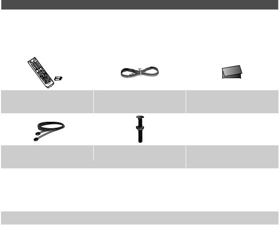
Accessories
Please make sure the following items are included with your LED TV. If any items are missing, contact your dealer.The items’ color and shape may vary, depending on the model.
The parts for the stand are listed under Stand Components on the following page.
List of Parts
yy Remote Control (AA59-00817A) & |
yy |
Power Cord |
yy Safety Guide / Quick Setup Guide |
|
Batteries (AAA x 2) |
(Not available in all locations) |
|||
|
|
yy Data Cable (depending on the |
|
|
model) |
yy Hotel Mount Kit |
yy Holder-Wire stand 1(EA) |
(BN39-00865B, BN39-01011C) |
|
|
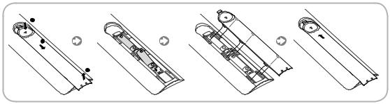
yy Assembling the Holder Wire Stand
4 English
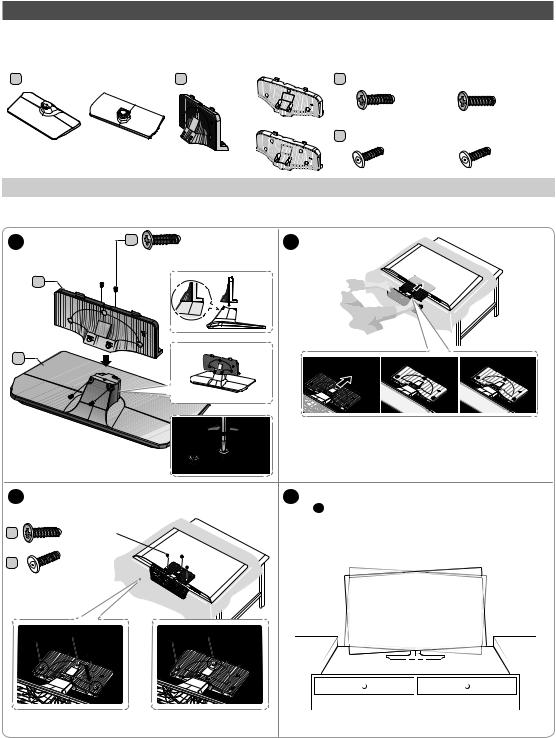
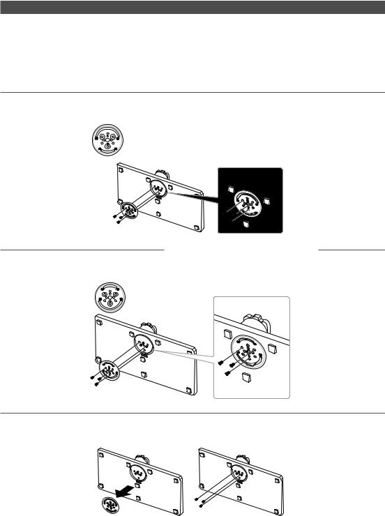
Installing the LED TV Stand
Components
When installing the stand, use the provided components and parts.
A 1 EA |
B 1 EA |
C |
28" ~ 32" |
40" ~ 55" |
|
|
|
|
x7 (M4 X L12) |
x8 (M4 X L12) |
|
|
|
32" |
|
|
|
|
|
D |
28" ~ 32" |
40" ~ 55" |
|
|
28" |
|
x3 (M4 X L12, |
x4 |
(M4 X L12, |
|
40" ~ 55" |
SECURITY) |
SECURITY) |
||
|
|
||||
|
|
|
|
|
|
• Stand |
• |
Guide Stand |
• Screws |
|
|
HG28NC690
1 |
C |
x4 |
2 |
|
|
(M4 X L12) |
|
B
A
|
|
|
Place a soft cloth over the table to protect the TV, and then place |
|
|
|
the TV on the cloth screen-side down. |
|
|
|
Insert the Stand Guide into the slot on the bottom of the TV. |
|
|
|
Slide and assemble it to the end line in the direction of arrow. |
3 |
Tight the bottom of the screw first, and stow the |
4 |
When the declination happened, try reassemble |
|
upper side of screw last. |
|
it 2 category. |
C |
x3 (M4 X L12) |
Make sure to assembling stand guide attached on the TV. |
|
|
|
||
D |
x3 (M4 X L12, |
|
|
SECURITY) |
|
|
|
Progress the assembly of screw in the manual’s order.
English 5

HG32NC690 / HG40NC690 / HG48NC690 / HG55NC690
1 |
2 |
C 


 x4 (M4 X L12)
B
40" ~ 55"
A
32"
32"
40" ~ 55"
Place a soft cloth over the table to protect the TV, and then place the TV on the cloth screen-side down.
Insert the Stand Guide into the slot on the bottom of the TV.Slide and assemble it to the end line in the direction of arrow.
3Tight the bottom of the screw first, and stow the upper side of screw last.
Progress the assembly of screw in the manual’s order.
|
32" |
40"~ 55" |
C |
x3 (M4 X L12) |
|
D |
x3 (M4 X L12, |
|
SECURITY) |
|
40" ~ 55"
C 


 x4 (M4 X L12)
D |
x4 (M4 X L12, |
|
SECURITY) |
4 When the declination happened, try reassemble it 2 category.
Make sure to assembling stand guide attached on the TV.
NOTE
yy Make sure to distinguish between the front and back of each component when assembling them. yy Make sure that at least two persons lift and move the TV.
6 English
Assembling the swivel (32 inch TVs or larger)
]]WARNING: If you configure the TV to swivel, you must attach it securely to the floor, a desk, a dresser top, etc. as described in the installation instructions.
The 32” and larger LED TVs have swivel stands. You can configure these stands so that the TVs swivel 20 degrees left and right, 60 degrees left and right, or 90 degrees left and right using the BRACKET HOLDER SWIVEL.
¦¦ 20° swivel
To configure the TV so that it swivels 20° left and right, insert the prong on the bottom of the stand through the curved hole in the Bracket Holder Swivel marked 20°. Then, fix the Bracket Holder Swivel to the stand using the three supplied screws as shown below.
¦¦ 60° swivel
To configure the TV so that it swivels 60° left and right, insert the prong on the bottom of the stand through the curved hole in the Bracket Holder Swivel marked 60°. Then, fix the Bracket Holder Swivel to the stand using the three supplied screws as shown below.
¦¦ 90° swivel
To configure the TV so that it swivels 90° left and right, remove the Bracket Holder Swivel, and then screw the three supplied screws into the stand as shown below.
English 7
¦¦ Hotel Mount Kit
Bolt + Nut
Short Bolt (2EA) |
Long Bolt (2EA) |
Nut (2EA) |
Washer (2EA) |
Top
|
Affix the stand to a flat surface such as a |
Bottom |
dresser top, desk top, or entertainment center as |
|
shown. |
[ |
WARNING: To prevent injury, you must attach this TV securely to the floor, a table, a dresser top, etc. with |
the Hotel Mount Kit as described in these instructions. |
8 English
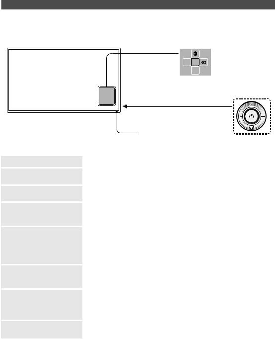
Using the TV's Controller
The color and shape of the TV Controller may vary depending on the model.
The TV's Controller, a small joy stick like button on the bottom right side of the TV, lets you control the TV without the remote control.
|
|
Open Smart Hub. |
|
||
|
|
|
|
|
|
|
Open the menu. |
m R |
|
|
Select a source. |
|
|
||||
|
|
P |
|
||
|
|
|
|
|
|
|
|
Turn off the TV. |
|
||
|
|
|
|
TV Controller |
|
|
The control stick is located at the lower-left |
||||
|
|
corner on the back of the TV. |
|||
|
Remote control sensor |
|
|||
|
When you use the Remote control, the |
|
|||
|
standby LED does not respond, except |
|
|||
|
when you press the P button. |
|
|||
Power on |
Turn the TV on by pressing the Controller when the TV is in standby mode. |
||||
Adjusting the volume |
Adjust the volume by moving the Controller from side to side when the |
||||
|
power is on. |
|
|||
Selecting a channel |
Select a channel by moving the Controller backwards and forwards when |
||||
|
the power is on. |
|
|||
Using the Function menu |
To view and use the Function menu, press and release the Controller |
||||
|
when the power is on. To close the Function menu, press and release the |
||||
|
Controller again. |
|
|||
Selecting the MENU (m) |
With the Function menu visible, select the MENU (m) by moving the |
||||
|
Controller to the left. The OSD (On Screen Display) Menu appears. Select an |
||||
|
option by moving the Controller to the right. Move the Controller to the right |
||||
|
or left, or backwards and forwards to make additional selections. To change |
||||
|
a parameter, select the it, and then press the Controller. |
||||
Selecting SMART HUB (™) |
With the Function menu visible, select SMART HUB (™) by moving the |
||||
|
Controller upwards. The SMART HUB main screen appears. Select an |
||||
|
application by moving the Controller, and then pressing the Controller. |
||||
Selecting a Source (s) |
With the Function menu visible, open the Source screen (s) by pushing |
||||
|
the Controller to the right. The Source screen appears. To select a |
||||
|
source, move the Controller back and forth. When the source you want is |
||||
|
highlighted, press the Controller. |
|
|||
Power Off (P) |
With the Function menu visible, select Power Off (P) by pulling the |
||||
|
Controller forwards, and then press the Controller. |
|
|||
To close the Menu, SMART HUB, or Source, press the Controller for more than 1 second.
Standby mode
Your TV enters Standby mode when you turn it off, and continues to consume a small amount of electric power. To be safe and to decrease power consumption, do not leave your TV in standby mode for long periods of time (when you are away on vacation, for example). It is best to unplug the power cord.
English 9
HG28NC690**
HG32NC690**
HG40NC690**
HG48NC690**
HG55NC690**
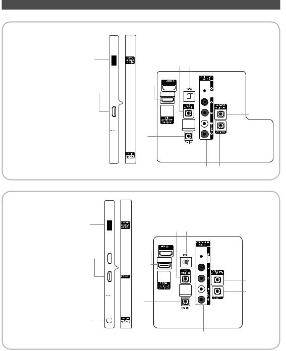
The Connection Panel
1 |
@ ! |
|
2
 2
2


 5
5

3

 6
6


7
4

1 |
@ ! |
|
VIDEO
0
8 9
2
 2
2


5

3

 6
6


7
4
VIDEO
0
9
8
10 English
Whenever you connect an external device to your TV, make sure that power on the TV and the device is turned off.When connecting an external device, match the color of the connection terminal to the cable.
1USB (HDD/1.0A) / CLONING
––Connector for software upgrades and Media Play, etc.
––Service connection.
2HDMI IN 1, 2, 3(ARC), 4(DVI): Connects to the HDMI jack of a device with an HDMI output.
No separate sound connection is needed for an HDMI to HDMI connection. HDMI connections carry both audio and video.
Use the HDMI IN 4(DVI) jack for a DVI connection to an external device. Use a DVI to HDMI cable or DVI-HDMI adapter (DVI to HDMI) for the video connection and the PC/DVI AUDIO IN jacks for audio. Some DVI or HDMI devices may not or should not need a DVI AUDIO IN connection for audio.
It is recommended that the external device of the HDMI 1.3 or 1.4 version will be used with this TV. If you meet the compatible problem like no sound or the abnormal screen or etc with the device of the HDMI 1.2 version, contact to the Samsung customer care center. Refer to page 52 for the information of the Samsung customer care center.
3LAN: Connect to a wired LAN using CAT 7 cable.
4ANT IN (AIR/CABLE)
––To view television channels correctly, the TV must receive a signal from one of the following sources:
––An outdoor antenna / A cable television system / A satellite receiver
5DIGITAL AUDIO OUT (OPTICAL): Connects to a Digital Audio component.
6AUDIO OUT: Connects to the audio input jacks on an Amplifier/Home Theater.
7EX-LINK: Connect this jack to the jack on the optional RJP (Remote Jack Pack). This will allow you to connect external devices (Camcoder, PC, DVD players etc.) easily.
8COMPONENT IN / AV IN
––Use to connect to Component video / audio devices such as DVD players and AV (Composite) devices such as VCRs.
––Connect audio cables to "R-AUDIO-L" on your TV and the other ends to corresponding audio out jacks on A/V or Component devices.
––The COMPONENT IN jack is also used as the VIDEO 1 jack.
––Connect component video cables (not supplied) to the component jacks ("PR", "PB", "Y") on the rear of your TV and the other ends to corresponding component video out jacks on a DVD player. Match the colors on the jacks and cables.
––If you want to connect both a Set-Top Box and a DVD player, you should connect the Set-Top Box to the DVD and connect the DVD to the component jacks ("PR", "PB", "Y") on your TV.
––The PR, PB and Y jacks on your component devices (DVD) are sometimes labeled Y, B-Y and R-Y or Y, Cb and Cr.
––For AV devices, connect RCA audio cables (not supplied) to "R - AUDIO - L" on the rear of the TV set and the other ends to corresponding audio out jacks on an external device.
––When your are connecting a composite (AV) device to AV IN1 [Y/Video], connect the video cable (Yellow) to the AV IN1 [Y/VIDEO] jack (Green/Yellow) .
9VOL-CTRL: Used to control the volume of the Bathroom speaker. Connect the Bathroom Wall Box and the VOLCTRL port.
0 VARIABLE AUDIO OUT: Used for the audio output to the Bathroom speaker. Connect the Bathroom Wall Box and the Variable port (RCA).
! DATA
––Used to support data communication between the TV and the SBB or STB.
––Connects using RJ-12 TV type plugs.
@DVI AUDIO IN: Connects to the audio out jack of an external DVI device using a 1/8th inch stereo phone jack cable.
Some DVI devices may not or should not need this connection audio.
English 11
The Remote Control
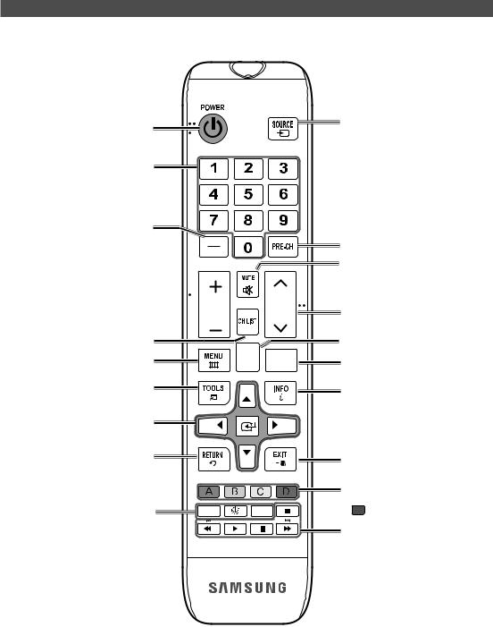
This remote control has Braille points on the Power, Channel, and Volume buttons and can be used by visually impaired customers.
Turns the TV on and off.
Press to directly access channels.
Press to select additional digital channels being broadcast by the same station. For example, to select channel ‘54-3’, press ‘54’, then press '-' and ‘3’.
Adjust the volume.
Display the channel list on the screen.
Display the main on-screen menu.
Quickly select frequently used functions.
Select on-screen menu items and change menu values.
Return to the previous menu.
 VOL CH
HOME CONTENT
Display and select the available video sources.
Return to the previous channel.
Cut off the sound temporarily.
Change channels.
Switch to the HOME Screen.
Displays My Contents, Watch TV and
Source icons on the TV screen.
Press to display channel and TV information on the TV screen.
Exit the menu.
ALARM
SLEEP: Sets the Sleep Timer. X: Turns the 3D image on or off.
(Not available) CC: Controls the caption decoder.
Buttons used in Channel list, Media Play menu, etc.
 button: Enter the hour your want the TV to turn on.
Use these buttons in the Media Play and
Anynet+ modes.
12 English
Installing batteries (Battery size: AAA)
Match the polarity of the batteries to the symbols in the battery compartment.
X
Y
Z
After you have installed the batteries, use a screwdriver to screw in the screw that holds the battery cover closed.
NOTE
•• Use the remote control within 23~33 feet of the TV.
•• Bright light may affect the performance of the remote control. Avoid using near fluorescent lights or neon signs.
•• The color and shape of the remote may vary depending on the model.
English 13
Connecting to the Network
You can set up your TV so that it can access the SMART TV applications through your local area network (LAN) using a wired or wireless connection.
After you have “physically” connected your TV to your network, you must configure the network connection to complete the process. You can configure the connection after the Initial Setup process, through the TV’s menu.
Network Connection - Wireless
Connect the TV to the Internet using a standard wireless router or modem.
Wireless IP Router or Modem that has a DHCP Server
The LAN Port on the Wall
LAN Cable (Not Supplied)
Network Connection - Wireless
yy This Smart TV supports the IEEE 802.11a/b/g /n communication protocols. Samsung recommends using IEEE 802.11n. Otherwise, when you play video over a network connection, the video may not play smoothly.
yy To use a wireless network, the TV must be connected to a wireless router or modem. If the wireless router supports DHCP, the TV can use a DHCP or static IP address to connect to the wireless network.
yy Select a channel that is not currently in use for the wireless router. If the channel set for the wireless router is currently being used by another device, the result is usually interference and/or a communications failure.
yy Most wireless networks have an optional security system. To enable a wireless network's security system, you need to create a security key using characters and numbers, and then enter that key into the router through its menu. You then must enter this security key into any other devices you want to connect to the wireless network.
Network Security Protocols
The TV only supports the following wireless network security protocols:
yy Authentication Modes: WEP, WPAPSK, WPA2PSK
yy Encryption Types: WEP, TKIP, AES
In compliance with the newest Wi-Fi certification specifications, Samsung TVs do not support WEP or TKIP security encryption in networks running in the 802.11n mode.
If the wireless router supports WPS (Wi-Fi Protected Setup), you can connect the TV to your network using PBC (Push Button Configuration) or a PIN (Personal Identification Number). WPS automatically configures the SSID and WPA key settings.
Your Smart TV cannot connect to uncertified wireless routers.
14 English

Network Connection - Wired
There are three main ways to connect your TV to your network using cable, depending on your network setup. They are illustrated below:
|
TV Rear Panel |
The Modem Port on the Wall |
External Modem |
(ADSL / VDSL / Cable TV) |
|
Modem Cable (Not Supplied) |
LAN Cable (Not Supplied) |
|
|
TV Rear Panel |
|
The Modem Port on the Wall |
External Modem |
IP Router that has a |
|
(ADSL / VDSL / Cable TV) |
|||
DHCP Server |
|||
Modem Cable |
LAN Cable |
LAN Cable |
|
(Not Supplied) |
(Not Supplied) |
(Not Supplied) |
|
TV Rear Panel |
The LAN Port on the Wall |
LAN Cable (Not Supplied) |
The TV does not support network speeds less than or equal to 10Mbps.Use Cat 7 cable for the connection.
English 15
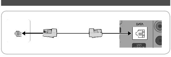
Connecting the TV to an SBB or STB
TV Rear Panel
Data Cable
1. Connect the DATA jack of the TV to the ETH MODEM jack of the STB (SBB) with the Data cable.
The "ETH MODEM" jack name that you connect the Data Cable to may differ depending on the SBB or STB type.
16 English
 Loading...