

Page 1
InView Firmware Update
Topic Page
Hazardous Voltage 3
Change EPROM on 2706-P72, 2706-P74 Display 3
Change EPROM on 2706-P42, 2706-P44 Displays 5
Firmware Upgrade Kit 7
Installation Instructions
Page 2
2 InView Firmware Update
Important User Information
Solid state equipment has operational characteristics differing from those of electromechanical equipment.
Safety Guidelines for the Application, Installation and Maintenance of Solid State Controls (Publication
SGI-1.1 available from your local Rockwell Automation sales office or online at
http://literature.rockwellautomation.com
equipment and hard-wired electromechanical devices. Because of this difference, and also because of the
wide variety of uses for solid state equipment, all persons responsible for applying this equipment must
satisfy themselves that each intended application of this equipment is acceptable.
In no event will Rockwell Automation, Inc. be responsible or liable for indirect or consequential damages
resulting from the use or application of this equipment.
The examples and diagrams in this manual are included solely for illustrative purposes. Because of the many
variables and requirements associated with any particular installation, Rockwell Automation, Inc. cannot
assume responsibility or liability for actual use based on the examples and diagrams.
No patent liability is assumed by Rockwell Automation, Inc. with respect to use of information, circuits,
equipment, or software described in this manual.
Reproduction of the contents of this manual, in whole or in part, without written permission of Rockwell
Automation, Inc., is prohibited.
Throughout this manual, when necessary, we use notes to make you aware of safety considerations.
) describes some important differences between solid state
WARNING
IMPORTANT
ATTENTION
SHOCK HAZARD
BURN HAZARD
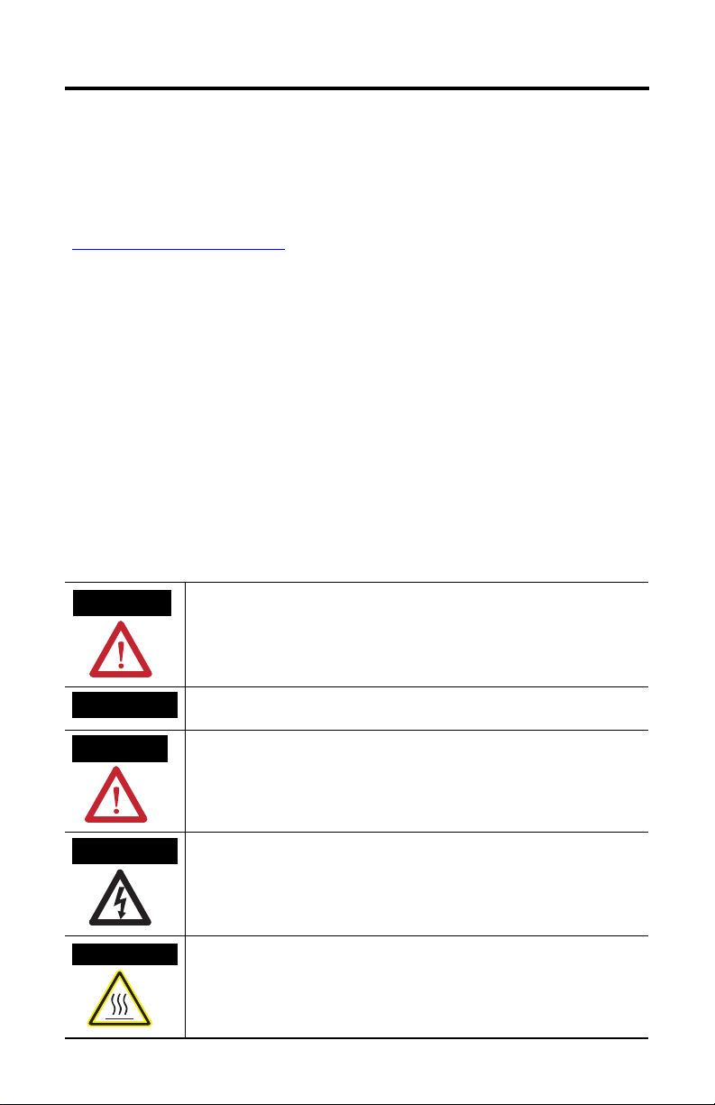
Identifies information about practices or circumstances that can cause an explosion in
a hazardous environment, which may lead to personal injury or death, property
damage, or economic loss.
Identifies information that is critical for successful application and understanding of
the product.
Identifies information about practices or circumstances that can lead to personal injury
or death, property damage, or economic loss. Attentions help you identify a hazard,
avoid a hazard and recognize the consequences.
Labels may be on or inside the equipment (for example, drive or motor) to alert people
that dangerous voltage may be present.
Labels may be on or inside the equipment (for example, drive or motor) to alert people
that surfaces may reach dangerous temperatures.
Publication 2706-IN009C-EN-P - June 2008
Page 3
Hazardous Voltage
InView Firmware Update 3
ATTENTION
Hazardous voltage. Contact with high voltage may cause death or serious injury. Always
disconnect power to sign prior to servicing.
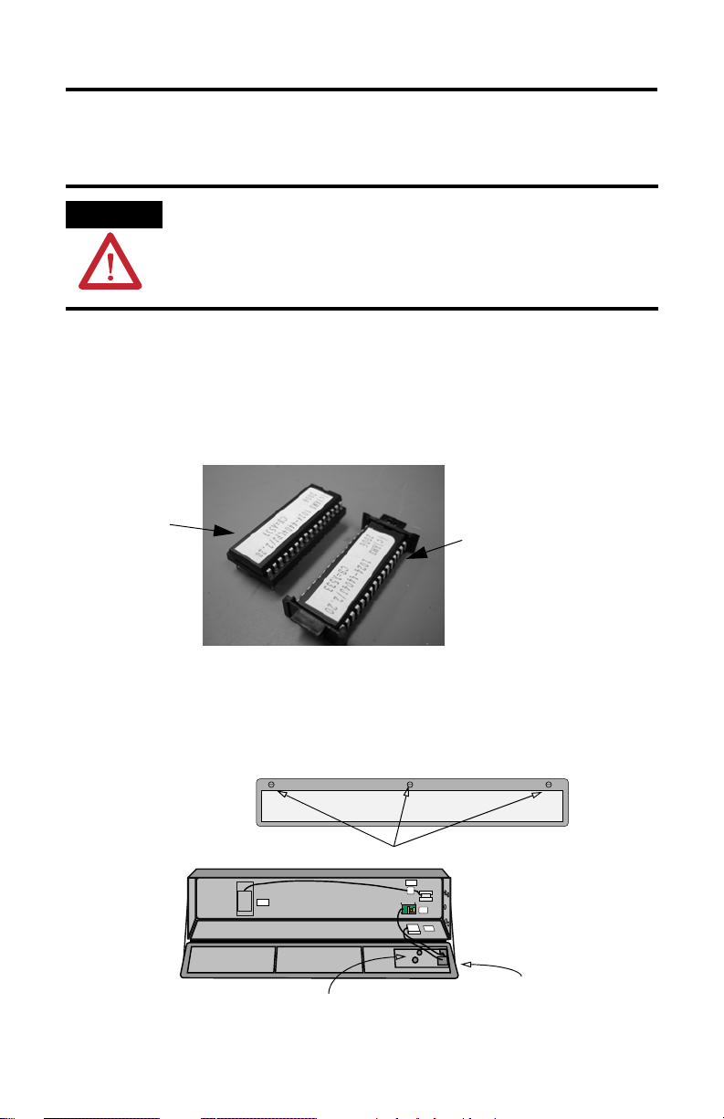
Change EPROM on 2706-P72, 2706-P74 Display
The firmware kit comes with two EPROMs. One is a chip carrier type and the other
is a round-pin DIP socket with the chip installed. Use the one that fits your
controller board.
Round-pin DIP Socket
Chip Carrier
Follow these steps to change the EPROM on the 2706-P72 and 2706-P74 displays.
1. Open the front of the sign case by turning the latches to the left.
Carefully let the front of the case drop forward.
Front View, Closed
Front View, Open
Quarter-turn Latches
Controller Board
Publication 2706-IN009C-EN-P - June 2008
POWER
LOAD
EARTH
GROUND
EPROM Unit (on
underside of board)
Page 4

4 InView Firmware Update
2. For the chip carrier type, on the underside of the controller board, firmly
pull down on the end tabs of the EPROM and carefully pull it out of the
socket.
End View (right end) of
Controller Board
Controller Board
Edge of
Sign Case
EPROM in Socket
3. For the round-pin DIP socket type, use a small screwdriver to pry the two
sockets apart.
TIP
Note the location of the pin 1 identifier for reference while installing the new chip.
.
4. Matching the side notches of the new EPROM to the socket, press the new
EPROM firmly into the socket.
The notch is at pin 1 on the EPROM.
5. Carefully close the sign and tighten the latches.
Publication 2706-IN009C-EN-P - June 2008
Page 5

InView Firmware Update 5
Change EPROM on 2706-P42, 2706-P44 Displays
The firmware kit comes with two EPROMs. One is a chip carrier type and the other
is a round-pin DIP socket with the chip installed. Use the one that fits your
controller board.
Round-pin DIP Socket
Chip Carrier
The EPROM is located at the end of the sign opposite the power supply.
Follow these steps to change the EPROM on the 2706-P42, and 2706-P44 displays.
1. Remove the four screws holding the end cover by using a #2 Phillips
screwdriver.
Power Supply
Publication 2706-IN009C-EN-P - June 2008
Page 6

6 InView Firmware Update
2. For the chip carrier type, firmly pull down on the end tabs of the EPROM
and carefully pull it out of the socket.
EPROM
3. For the round-pin DIP socket type, use a small screwdriver to pry the two
sockets apart.
TIP
Note the location of the pin 1 identifier for reference while installing the new chip.
.
4. Matching the side notches of the new EPROM to the socket, press the new
EPROM firmly into the socket.
5. Replace the end cover and screws and torque end cover screws to 2.7 N
•in).
(24 lb
•m
Publication 2706-IN009C-EN-P - June 2008
Page 7

InView Firmware Update 7
Firmware Upgrade Kit
These are the available InView display firmware-upgrade kits.
Product Cat. No. Firmware Upgrade Kit Cat. No.
2706-P42R 2706-FRNP42R
2706-P42C 2706-FRNP42C
2706-P44R 2706-FRNP44R
2706-P44C 2706-FRNP44C
2706-P72CN1 and 2706-P72CN2 2706-FRNP72C
2706-P74CN1 and 2706-P74CN2 2706-FRNP74C
Publication 2706-IN009C-EN-P - June 2008
Page 8

Rockwell Automation Support
Rockwell Automation provides technical information on the Web to assist you in
using its products. At http://support.rockwellautomation.com
technical manuals, a knowledge base of FAQs, technical and application notes,
sample code and links to software service packs, and a MySupport feature that you
can customize to make the best use of these tools.
For an additional level of technical phone support for installation, configuration and
troubleshooting, we offer TechConnect support programs. For more information,
contact your local distributor or Rockwell Automation representative, or visit
ttp://support.rockwellautomation.com.
h
Installation Assistance
If you experience a problem within the first 24 hours of installation, please review
the information that's contained in this manual. You can also contact a special
Customer Support number for initial help in getting your product up and running.
, you can find
United States 1.440.646.3434
Outside United
States
Monday – Friday, 8 a.m. – 5 p.m. EST
Please contact your local Rockwell Automation representative for any
technical support issues.
New Product Satisfaction Return
Rockwell Automation tests all of its products to ensure that they are fully
operational when shipped from the manufacturing facility. However, if your
product is not functioning and needs to be returned, follow these procedures.
United States Contact your distributor. You must provide a Customer Support case number
Outside United
States
Allen-Bradley, Rockwell Automation, InView, and TechConnect are trademarks of Rockwell Automation, Inc.
Trademarks not belonging to Rockwell Automation are property of their respective companies.
(call the phone number above to obtain one) to your distributor in order to
complete the return process.
Please contact your local Rockwell Automation representative for the return
procedure.
Publication 2706-IN009C-EN-P - June 2008 PN 41061-268-01(3)
Supersedes Publication 2706-IN009B-EN-P - March 2002 Copyright © 2008 Rockwell Automation, Inc. All rights reserved. Printed in the U.S.A.
 Loading...