

Page 1
Allen-Bradley
Bulletin 2706 Dataliner
Message Display DL5
Series
User Manual
Page 2

Important User Information
!
Because of the var iety o f uses for t he product s des cribed in this publi catio n,
those responsible for t he appli cati on and us e of thi s cont rol equ ipmen t must
satisfy themselves that all necessary steps have been taken to assure that
each application and use meets all performance and safety requirements,
including any applicable laws, regulations, codes and standards.
The illustrations, charts, sample programs and layout examples shown in
this guide are inte nded solely for purposes of exampl e. Since there ar e many
variables and requirements associated with any particular installation,
Allen-Bradley does not assume responsibility or liability (to include
intellectual p roperty liabi lity) for actual use b ased upon t he examples sh own
in this publication.
Allen-Bradley publication SGI-1.1, Safety Guidelines for the Application,
Installation and Maintenance of Solid-State Control (available from your
local Allen-Bradley office), describes some important differences between
solid-state equipment and electromechanical devices that should be taken
into consideration when applying products such as those described in this
publication.
Reproduction of the contents of this copyrighted publication, in whole or
part, without written permission of Rockwell Automation, is prohibited.
Throughout this manual we use notes to make you aware of safety
considerations:
ATTENTION: Identifies information about practices or
circumstances that can lead to personal injury or d eath,
property damage or economic loss
Attention statements help you to:
• identify a hazard
• avoid a hazard
• recognize the consequences
Important:Identifies information th at is critical for successful application
and understanding of the product.
Allen-Bradley is a trademark of Rockwell Automation
Page 3

Table of Contents
Using this Manual
Chapter Objectives . . . . . . . . . . . . . . . . . . . . . . . . . . . . . . . . . . . . P-1
Overview. . . . . . . . . . . . . . . . . . . . . . . . . . . . . . . . . . . . . . . . . . . . .P-1
Intended Audience . . . . . . . . . . . . . . . . . . . . . . . . . . . . . . . . . . . . P-2
Conventions . . . . . . . . . . . . . . . . . . . . . . . . . . . . . . . . . . . . . . . . . P-2
1 - Introduction to the DL5
Chapter Objectives . . . . . . . . . . . . . . . . . . . . . . . . . . . . . . . . . . . . 1-1
Overview. . . . . . . . . . . . . . . . . . . . . . . . . . . . . . . . . . . . . . . . . . . . 1-1
Main Features . . . . . . . . . . . . . . . . . . . . . . . . . . . . . . . . . . . . . . . . 1-2
Memory Storage Capacity . . . . . . . . . . . . . . . . . . . . . . . . . . . . . . 1-3
Programming Software. . . . . . . . . . . . . . . . . . . . . . . . . . . . . . . . . 1-3
Programming Cables. . . . . . . . . . . . . . . . . . . . . . . . . . . . . . . . . . . 1-3
2 - Getting Started
Chapter Objectives . . . . . . . . . . . . . . . . . . . . . . . . . . . . . . . . . . . . 2-1
Initial Desktop Hookup. . . . . . . . . . . . . . . . . . . . . . . . . . . . . . . . . 2-1
Initial Desktop Setup . . . . . . . . . . . . . . . . . . . . . . . . . . . . . . . . . . 2-2
Initial Power Up of the DL5 . . . . . . . . . . . . . . . . . . . . . . . . . . . . . 2-4
Responding to a Yes or No Prompt . . . . . . . . . . . . . . . . . . . . . . . 2-6
Responding to a Numeric Prompt. . . . . . . . . . . . . . . . . . . . . . . . . 2-7
Responding to a Mnemonic Prompt . . . . . . . . . . . . . . . . . . . . . . . 2-8
Using the Main Menu . . . . . . . . . . . . . . . . . . . . . . . . . . . . . . . . . . 2-9
Returning to the Main Menu. . . . . . . . . . . . . . . . . . . . . . . . . . . . 2-10
Using the Control Key . . . . . . . . . . . . . . . . . . . . . . . . . . . . . . . . 2-10
Table of Contents
toc-iii
Page 4

Ta ble of Contents
3 - Entering New Messages
Chapter Objectives . . . . . . . . . . . . . . . . . . . . . . . . . . . . . . . . . . . . 3-1
Edit vs. Run Mode . . . . . . . . . . . . . . . . . . . . . . . . . . . . . . . . . . . . 3-1
Selecting the Edit Mode . . . . . . . . . . . . . . . . . . . . . . . . . . . . . . . . 3-1
Edit Mode Menu. . . . . . . . . . . . . . . . . . . . . . . . . . . . . . . . . . . 3-2
Specifying Message Attributes. . . . . . . . . . . . . . . . . . . . . . . . . . . 3-3
Line Selection . . . . . . . . . . . . . . . . . . . . . . . . . . . . . . . . . . . . . 3-3
Selecting Line or Scroll Mode . . . . . . . . . . . . . . . . . . . . . . . . 3-5
Selecting Message Wait Time . . . . . . . . . . . . . . . . . . . . . . . . 3-5
Auto Clear Option. . . . . . . . . . . . . . . . . . . . . . . . . . . . . . . . . . 3-6
Auto Repeat Option . . . . . . . . . . . . . . . . . . . . . . . . . . . . . . . . 3-6
Flash Message Option. . . . . . . . . . . . . . . . . . . . . . . . . . . . . . . 3-6
Default Values for Message Attributes. . . . . . . . . . . . . . . . . . . . . 3-7
Entering a Message. . . . . . . . . . . . . . . . . . . . . . . . . . . . . . . . . . . . 3-7
Embedding Numeric Variable Data in A Message. . . . . . . . . 3-9
Entering a Sample Message . . . . . . . . . . . . . . . . . . . . . . . . . . . . . 3-9
Programming Multiple DL5s Identically . . . . . . . . . . . . . . . . . . 3-11
4 - Reviewing and Editing Messages
Chapter Objectives . . . . . . . . . . . . . . . . . . . . . . . . . . . . . . . . . . . . 4-1
Reviewing a Message . . . . . . . . . . . . . . . . . . . . . . . . . . . . . . . . . . 4-1
Displaying the Amount of Memory Remaining. . . . . . . . . . . . . . 4-2
Selecting a Message to Edit . . . . . . . . . . . . . . . . . . . . . . . . . . . . . 4-3
Moving the Cursor . . . . . . . . . . . . . . . . . . . . . . . . . . . . . . . . . . . . 4-3
Deleting a Character . . . . . . . . . . . . . . . . . . . . . . . . . . . . . . . . . . . 4-4
Deleting a Message Block . . . . . . . . . . . . . . . . . . . . . . . . . . . . . . 4-4
Inserting a Message Block . . . . . . . . . . . . . . . . . . . . . . . . . . . . . . 4-5
Deleting an Entire Message . . . . . . . . . . . . . . . . . . . . . . . . . . . . . 4-5
Editing Message Attributes. . . . . . . . . . . . . . . . . . . . . . . . . . . . . . 4-6
toc--iv
Page 5

5 - Run Mode
Chapter Objectives . . . . . . . . . . . . . . . . . . . . . . . . . . . . . . . . . . . . 5-1
Entering Run Mode. . . . . . . . . . . . . . . . . . . . . . . . . . . . . . . . . . . . 5-1
Run Mode - Parallel Operation. . . . . . . . . . . . . . . . . . . . . . . . . 5-1
Run Mode - Serial Operation . . . . . . . . . . . . . . . . . . . . . . . . . . 5-2
Description of Run Mode . . . . . . . . . . . . . . . . . . . . . . . . . . . . . . . 5-2
6 - Using the Serial Port
Chapter Objectives . . . . . . . . . . . . . . . . . . . . . . . . . . . . . . . . . . . . 6-1
Programming Cables. . . . . . . . . . . . . . . . . . . . . . . . . . . . . . . . . . . 6-1
RS-232 Signals . . . . . . . . . . . . . . . . . . . . . . . . . . . . . . . . . . . . . . . 6-2
Serial Port Protocol. . . . . . . . . . . . . . . . . . . . . . . . . . . . . . . . . . . . 6-3
Message Trigger [Ctrl][T] . . . . . . . . . . . . . . . . . . . . . . . . . . . 6-3
Variable Data [CTRL][V]. . . . . . . . . . . . . . . . . . . . . . . . . . . . 6-3
7 - Using the Para llel Port
Chapter Objectives . . . . . . . . . . . . . . . . . . . . . . . . . . . . . . . . . . . . 7-1
Description of the Parallel Port. . . . . . . . . . . . . . . . . . . . . . . . . . . 7-1
Selecting BCD or Binary Data Format. . . . . . . . . . . . . . . . . . . . . 7-3
Using Binary Data Input. . . . . . . . . . . . . . . . . . . . . . . . . . . . . . . . 7-4
Using BCD Data Input . . . . . . . . . . . . . . . . . . . . . . . . . . . . . . . . . 7-5
Logic Levels . . . . . . . . . . . . . . . . . . . . . . . . . . . . . . . . . . . . . . . . . 7-6
Using the Numeric (Run) Mode . . . . . . . . . . . . . . . . . . . . . . . . . . 7-7
Numeric Mode and Autorun Message . . . . . . . . . . . . . . . . . . . . 7-10
Using DC Outputs to Trigger the DL5 . . . . . . . . . . . . . . . . . . . . 7-11
Determining Current Requirements For DC Outputs. . . . . . 7-12
Parallel Port Power Supply Requirements . . . . . . . . . . . . . . . . . 7-13
Timing Requirements of the Parallel Port . . . . . . . . . . . . . . . . . 7-13
Table of Contents
8 - Special Functions
Chapter Objectives . . . . . . . . . . . . . . . . . . . . . . . . . . . . . . . . . . . . 8-1
Introducing the Special Functions Menu . . . . . . . . . . . . . . . . . . . 8-1
Entering the Special Functions Menu. . . . . . . . . . . . . . . . . . . . . . 8-3
SET PORT Special Function . . . . . . . . . . . . . . . . . . . . . . . . . . . . 8-4
Run Mode Special Functions . . . . . . . . . . . . . . . . . . . . . . . . . . . . 8-5
Debug Special Function . . . . . . . . . . . . . . . . . . . . . . . . . . . . . . . . 8-6
CLEAR MEMORY Special Function . . . . . . . . . . . . . . . . . . . . . 8-7
SET AUTORUN Special Function. . . . . . . . . . . . . . . . . . . . . . . . 8-7
toc-v
Page 6

Ta ble of Contents
9 - Using the Variable Data Feature
Chapter Objectives . . . . . . . . . . . . . . . . . . . . . . . . . . . . . . . . . . . . 9-1
Variable Data Limits. . . . . . . . . . . . . . . . . . . . . . . . . . . . . . . . . . . 9-1
Creating Messages with Embedded Variable Data. . . . . . . . . . . . 9-2
Embedding a Decimal Point . . . . . . . . . . . . . . . . . . . . . . . . . . . . . 9-3
Sending Variable Data Through the Serial Port . . . . . . . . . . . . . . 9-3
Sending Variable Data Through the Parallel Port . . . . . . . . . . . . 9-4
Parallel Port Strobe and Data Bits . . . . . . . . . . . . . . . . . . . . . 9-4
Parallel Port Timing Requirements. . . . . . . . . . . . . . . . . . . . . . . . 9-5
Suggestions on Using the Variable Data Feature . . . . . . . . . . . . . 9-7
10 - Using the DL5 Parallel Port to Replace Pilot Lights
Chapter Objectives . . . . . . . . . . . . . . . . . . . . . . . . . . . . . . . . . . . 10-1
Description of Input Modes . . . . . . . . . . . . . . . . . . . . . . . . . . . . 10-1
Round Robin Mode. . . . . . . . . . . . . . . . . . . . . . . . . . . . . . . . . . . 10-2
Priority Mode . . . . . . . . . . . . . . . . . . . . . . . . . . . . . . . . . . . . . . . 10-4
Using the Round Robin Input Mode. . . . . . . . . . . . . . . . . . . . . . 10-5
Using Priority Input Mode . . . . . . . . . . . . . . . . . . . . . . . . . . . . . 10-6
11 - Using the DL5 to Replace BCD Displays and Lookup Tables
Chapter Objectives . . . . . . . . . . . . . . . . . . . . . . . . . . . . . . . . . . . 11-1
Replacing a BCD Fault Code Display . . . . . . . . . . . . . . . . . . . . 11-1
12 - Installation Instr uctions
Chapter Objectives . . . . . . . . . . . . . . . . . . . . . . . . . . . . . . . . . . . 12-1
Grounding. . . . . . . . . . . . . . . . . . . . . . . . . . . . . . . . . . . . . . . . . . 12-1
Wire Routing. . . . . . . . . . . . . . . . . . . . . . . . . . . . . . . . . . . . . . . . 12-1
Mounting the DL5 . . . . . . . . . . . . . . . . . . . . . . . . . . . . . . . . . . . 12-2
Power Supply Requirement . . . . . . . . . . . . . . . . . . . . . . . . . . . . 12-4
Power/Parallel Port Wiring. . . . . . . . . . . . . . . . . . . . . . . . . . . . . . 12-6
13 - Maintenance and Tr oubleshooting
Troubleshooting Chart . . . . . . . . . . . . . . . . . . . . . . . . . . . . . . . . 13-1
14 - Specifications
Electrical. . . . . . . . . . . . . . . . . . . . . . . . . . . . . . . . . . . . . . . . . . . 14-1
Environmental. . . . . . . . . . . . . . . . . . . . . . . . . . . . . . . . . . . . . . . 14-2
Display Characteristics . . . . . . . . . . . . . . . . . . . . . . . . . . . . . . . . 14-3
Programming . . . . . . . . . . . . . . . . . . . . . . . . . . . . . . . . . . . . . . . 14-3
toc--vi
Page 7

A - ASCII Character Set
B - Cabling Diagrams
Abreviations . . . . . . . . . . . . . . . . . . . . . . . . . . . . . . . . . . . . . . . . . B-1
Allen-Bradley T3 Terminal
Serial Communications Cable (Catalog No. 2706-NC15) . . . . . . B-1
Allen-Bradley 1745-T45 Terminal, VT100 or IBM XT & Compatibles
Serial Communications Cable (Cat. No. 2706-NC12) . . . . . . . . . .B-2
Allen-Bradley 6121 or T50 Terminal, IBM AT & Compatibles
Serial Communications Cable (Cat.No. 2706-NC13) . . . . . . . . . .B-2
Allen-Bradley 6120 or Industrial PC / XT
Serial Communications Cable (Cat. No. 2706-NC14) . . . . . . . . . .B-3
C - Message Display Worksheets
D - Application Notes
Unsigned Integer Conversion . . . . . . . . . . . . . . . . . . . . . . . . . . . D- 1
Table of Contents
toc-vii
Page 8

Ta ble of Contents
toc--viii
Page 9

Using this Manual
Preface
Chapter Objectives
Read this chapter to famil iarize yourself with the rest of the manual. You
will learn about:
• Contents of this manual
• Intended audience
• Conventions used
This manual will i nstru ct you on how to in stal l and u se your Datal iner DL5.
display. The manual is divided into the following chapters:
Chapter Title Purpose
Preface Using this Manual Provides an overview of the manual.
1 Introduction to the DL5 Describes the main features and operating
capabilities of the DL5.
2 Getting Started Provides instructions for the initial desktop
setup along with a description of the menus
and prompts.
3 Entering New Messages Provides step-by-step instructions on how
to enter a message along with message
attributes.
4 Reviewing and Editing
Messages
Provides instructions on reviewing and
editing previously entered messages.
5 The Run Mode Describes the operation of the DL5 while in
the run mode.
6 Using the Serial Port Describes the operation of the serial port.
7 Using the Parallel Port Describes the connection and operation of
the parallel port.
8 Special Functions Describes the functions available under the
Special Functions menu.
9 Using the Variable Data
Feature
10 Using the DL5 Parallel Port
to Replace Pilot Lights
11 Using the DL5 to Replace
BCD Displays and Lookup
Tabl es
12 Installation Instructions Describes the installation requirements for
Provides instructions on how to embed
variable data in a message.
Provides instructions on how to use the
DL5 Pilot Light replacement run modes.
Provides instructions on how to replace
BCD displays with a DL5.
mounting the display.
2706-UM001A-US-P
Page 10

P-2 Using this Manual
Chapter Title Purpose
13 Maintenance and
Troubleshooting
14 Specifications Electrical, mechanical, environmental
Appendices, Glossary, Index
Provides general maintenance instructions.
Also provides instructions on solving some
of the most common operating problems.
specifications
Intended Audience
Conventions
No special knowledge is needed to enter or edit messages. However, since
the Dataliner message display must be connected to peripheral equipment,
you should be familiar with computer communication terminology.
The following conventions are used:
• Messages displayed on the DL5 are shown inside a rectangular box.
(',7"
• A symbol or word in brackets represent a single key that you should
press. These include keys such as [A] or [Retrn].
• Since the DL5 can be programmed with a variety of terminals, the
printing on your terminal keyboard may be different than the symbol or
word indicated in brackets. In this manual, we use [ Retrn] to specify t he
carriage return function of the keyboard. On your keyboard this may
correspond to the [Enter] or [ ] keys.
• Angle brackets, < >, are used when you are to enter variable data. For
example, <message number> , means you are to enter a message number
at that point.
2706-UM001A-US-P
• In the following chapters, we refer to the Dataliner DL5 Series Message
Display as the DL5.
Page 11

Introduction to the DL5
Chapter 1
Chapter Objectives
Overview
This chapter briefly describes some of the key features and operating
capabilities of the DL5. If you require more detailed information, refer to
the section of the manual that describes the use of the feature or operating
capability.
The DL5 stores messages of varying length within its own memory. The
stored mes sages are displayed when the DL5 receives a command from
your control system. The messages can be used to show a status condition,
help diagnose a problem, or prompt an operator.
The Bulletin 2706 DL5 Series Dataliner Message Display (DL5) is
available with two display options:
• One line d i splay (16 ch aracters)
• Two line display (16 characters per line)
Note: The operation of the one and two line displays is similar. The few
exceptions are noted in this manual.
You can use a variety of devices to program the DL5
• The Allen-Bradley line of industrial terminals (T1 through T4).
• Most DTE type “dumb” terminals.
• DEC VT100, VT101 terminals.
• IBM compatible computers, including Allen-Bradley RAC6000
industrial computers, using the DL5 offline programming software
(Catalog No. 2706-NP5).
• The 16 character display can show a wide variety of characters and
symbols, including:
– Uppercase letters
– Punctuation
2706-UM001A-US-P
Page 12

1-2 Introduction to the DL5
Main Features
Serial or Parallel Triggering - Stored messages can be triggered by
sending messages to the DL5 serial or parallel ports. Both the serial and
parallel ports cannot be used at the same time. The Serial Trigger/
Configure DIP switch (S W1-1) on the back of the DL5 determines wh ich
port is used for triggering.
DC Input - The parallel port of the DL5 accepts 5-24 volts DC. DL5s are
powered by 12-24 volts DC.
Round Robin Mode - The round robin mode allows you to replace up to
sixteen pilot lights, that are being used as status indicators, with a single
DL5 display. Instead of your control system turning on a pilot light, it will
trigger a message for display.
Priority Mode - The priority mode is similar to the round robin mode.
However, the priority mode has an additional feature that allows you to
designate certain messages as more important than other messages. If two
or more messages are triggered at the same time, only the priority message
will be displayed.
Numeric Mode - The numeric mode allows you to use the DL5 as a
numeric only 3 or 4 digit (BCD) display. Your control system can transmit
real time binary coded decimal (BCD) data to the DL5 for immediate
display. Use the DL5 to display numbers as large as
999, 999, 999, 999, 999.
Binary or BCD Input Mode - Your control system can transmit data and
message triggers in eit her bina ry or Binary Coded Decimal (BCD) formats.
This allows the recall of up to:
• 94 messages with a one or two line 2K byte DL5
• 387 messages with a two line 8K byte DL5
Debug Mode - You can verify the operation of the program in a host
programmable controller (PLC) using the debug function of the DL5. The
debug mode will display the condition (ON or OFF) of the sixteen parallel
port data lines.
Note: Special application considerations may be necessary for some types
of controlling devices. Refer to Chapter 8 for more details.
2706-UM001A-US-P
Page 13

Introduction to the DL5 1-3
Memory Storage Capacity
Programming Software
Programming Cables
The DL5 stores messages in blocks of 16 characters. Message blocks can
be strung together to form messa ges longer than 16 char acters. The one and
two line 2Kbyte displa ys can st ore 94 mes sage bl ocks (16 charac ter s). The
two line 8Kbyte displays can accommodate up to 387 message blocks.
Both the one line and two line displ ays sto re messag es in an EEPROM. No
batteries for memory backup are required.
Allen-Bradley offers DL5 offline programming software (Catalog No.
2706-NP5) for IBM PC or compatible computers with a 3
1
/2 inch disk
drives. This includes Allen-Bradley RAC 6000 industrial computers.
The following offline programming cables are available.
Serial Cable Use with:
2706-NC12 Personal computers with 25-pin female communication port
connector. DEC VT52, VT100, or VT101 terminals. Allen-Bradley
RAC 6000 industrial computers.
2706-NC13 Personal computers with 9-pin female communication port
connector (IBM AT and compatible). Allen-Bradley RAC 6000
industrial computers.
2706-NC14 Allen-Bradley RAC 6000 industrial computers (PC/XT).
2706-NC15 Allen-Bradley Industrial Terminals T1 through T4 (25-pin male
connector).
2706-UM001A-US-P
Page 14

1-4 Introduction to the DL5
2706-UM001A-US-P
Page 15

Getting Started
Chapter 2
Chapter Objectives
Initial Desktop Hookup
In this chapter, you will learn how to set up the DL5 for desktop use. You
will also become familiar with the opening menus and prompts.
To begin desktop programming of the DL5, you must have the following
items:
• 12-24 VDC power supply.
• An Allen-Bradley Industrial Terminal (Catalog No. 1770-T1 through
1770-T4), a Data Terminal Equipment (DTE) type RS-232 “dumb”
terminal, a DEC VT52, VT100, or VT101 terminal
• Personal computer with DL5 offline programming software.
• Programming cable
Note: The terminal or host computer must initially operate with the
following protocol:
• 9600 baud rate
• 8 data bits
• no parity
• 1 stop bit
This is required for init ial communica tions with t he DL5. After init ial hook
up, change the baud rate using the DL5 menu.
2706-UM001A-US-P
Page 16
2-2 Getting Started
Initial Desktop Setup
To setup the DL5, perform the following steps:
Step 1
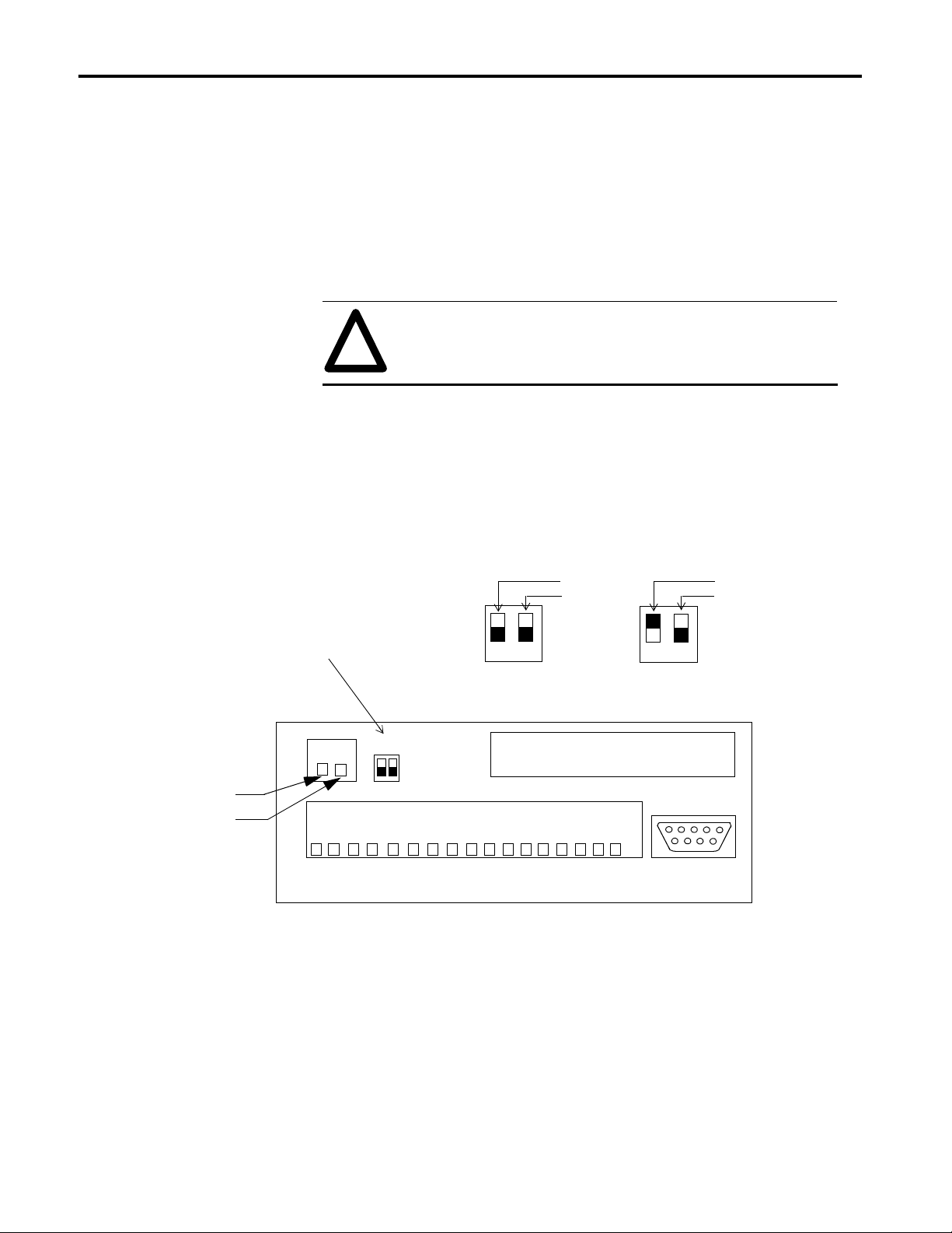
Connect DC power to the DC line terminals (TB2) on the back of the DL5.
Note: The input voltage must be between 12 and 24 volts DC.
ATTENTION:
!
The terminals are labeled as shown below.
For additional power supply requirements refer to the specifications listed
in Chapter 14.
DC Line Terminals , Configure/Serial Trigger Switch
Switch 1 (SW-1)
Enables Serial Trigger / Configure
UP = Serial Trigger
DOWN = Configure
To avoid system ground loops, the same power supply must
be used for the parallel port and the power input for the DL5.
DOWN
12
Configure
Not Used
Serial Trigger
Not Used
UP
12
COMMON
12-24V DC
2706-UM001A-US-P
1
TB1TB2
D0D1D2D3D4D5D6D7D8D9D10
SW1
PARALLEL PORT 5-24 VDC INPUT
12
2
TB2
1 COM
2 12-24V DC Input
D11
D12
D13
1 Serial Trigger/ Configure
2 Not Used
D14
D15
PD
SW1
RS-232
Step 2
Make sure the Serial Trigger / Configure switch is set to Confi gure (down).
Page 17

Getting Started 2-3
Step 3
Connect the programming device co mmunications cabl e. Attach one end of
the communications cable to an Allen-Bradley Industrial Terminal, a DTE
Terminal, or computer. Since there are variations between the connections
required, refer to the following guidelines:
• If you are using an Allen-Bradley Industrial Terminal, connect the “D”
type connector on the communications cable (Catalog No. 2706-NC15)
to port B on the terminal.
• If you are using a DTE type CRT terminal, connect the 2706-NC15
communications cable to the computer communications port on the
terminal. The comput er c ommu nicat ions p ort i s usua ll y lab eled “Main”,
“EIA”, or “RS-232”. Do not use the terminals labeled “Remote”,
“Printer”, or “Auxiliary”.
• If you are using a DEC VT52, VT100, or VT101, connect a Catalog
Number 2706-NC12 cable to the “Main” or “RS-232” port.
• If you are using a computer and DL5 offline software, connect the
appropriate progra mmi ng cable to the COM1 serial com munication port
of the computer.
Note: For cable requirements, see Chapter 6. Cable diagrams can be found
in Appendix B.
Step 4
Plug the other end of the communications cable into the connector labeled
RS-232 on the back of the DL5.
Step 5
• Set your terminal or computer COM1 port to operate at:
• 9600 baud rate (default of the DL5)
• 8 data bits
• no parity
• 1 stop bit
Important: Some terminals require that power be cycled off and then on
before changes to communications protocol take effect. If the DL5 had
been previously programmed, the baud rate may have been changed to
something other than 9600 baud (e.g., 300 or 1200). The DL5 will display
its baud rate on power up.
2706-UM001A-US-P
Page 18
2-4 Getting Started
Initial Power Up of the DL5
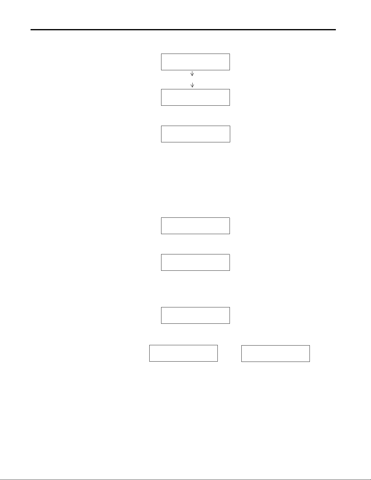
When DC power is applied to the DL5, it will display:
'//
9[[[
All of the light segments are turned on.
Two separate displays on 1-Line DL5
7(67,1*
Wait several seconds for the next display:
0(025<[.
The memory display indicates the device memory capacity:
• 2Kbyte for Catalog No. 2706-D11J2 and -D21J2
• 8Kbyte for Catalog No. 2706-D21J8.
The SELF TEST OK display indicates that all of the diagnostic tests have
been completed.
6(/)7(672.
After the di agnostic tests are completed the DL5 will display:
%$8'5$7(
Indicating the current baud rate of the RS-232 port. (Default is 9600 baud).
Then it will display the serial port address:.
$''5(66
And then depending on the DIP switch setting:
6(5,$/352*5$0
6(5,$/75,**(5
2706-UM001A-US-P
Page 19

Getting Started 2-5
Then the DL5 displays the current run mode: (Numeric, Priority, Round
Robin, Binary or BCD) Finally, it will indicate it is entering the run mode
and display the AUTORUN message.
Note: The DL5 will always come up (after power down) in a run mode.
This will be the last run mode that the unit was in befo re p ower down. The
initial (out-of-the-box) default mode is numeric.
Press the [ESC] (Escape) key three times to exit the run mode. You will
then be shown the RUN? prompt.
581"
Press [N] and [Retrn] and you will be shown the EDIT? prompt.
(',7"
You are now ready to enter messages as described in the next chapter. But
first you should become familiar with the DL5’s prompts and main menu.
2706-UM001A-US-P
Page 20

2-6 Getting Started
Responding to a Yes or No
Prompt
There are three types of prompts that require a response:
• Yes or No prompts
• Numeric prompts
• Mnemonic prompts
The yes or no prompts appear as a word or words followed by a question
mark (?). You must respond to a yes or no prompt with either t he let ter “Y”
(Yes) or the letter “N” (No). For example, the following prompt appears:
(',7"
If you press the [N] key (upper or lowercase), the display will show:
(',7"1
You can change your mind by pressing the [Y] key (upper or lowercase).
The display now shows:
(',7"<
Note: Only the letters “Y” or “N” are accepted as responses. You may
change your response as many times as you wo uld like prior to pre ssing the
[Retrn] (carriage return) key.
If you press the [Retrn] key the selection is entered into the DL5’s memo r y
and the next prompt will be displayed.
A variation of the yes or no prompt is the default prompt. The default
prompt provides an initial response or “default” for you. For example,
assume the following prompt is displayed:
)/$6+0(6*"1
If you press the [Retrn] key, the response “No” would be entered into the
DL5’s memory. If you press the [Y] key, the prompt response will change
as in the previous example:
)/$6+0(6*"<
2706-UM001A-US-P
Page 21

Getting Started 2-7
Responding to a Numeric
Prompt
The other type of prompt you will encounter is the numeric prompt. You
must respond to a numeric prompt with a number. A numeric prompt will
appear as a word or words followed by a colon (:). For exampl e, assume the
following prompt is displayed:
180%(5
If you were to press the key [2] the display would appear like this:
180%(5
Pressing the key [7] will cause the display to change as follows:
180%(5
Notice that the numbers that are ente red scr oll in f rom the right side. If you
really wanted to enter the number “5”, you could type the new number in
over the previous r espons e by fir st ty ping in fou r zeroe s (0000 ) foll owed by
the desired number “5”.
Pressing the [Retrn] key will now enter your response into the memory of
the DL5 and the next prompt will be displayed.
Numeric prompts may also have default values. For example, when the
following is displayed:
:$,77,0(
To record the number “5” as your response, press the [Retrn] key. If you
want to enter another value, type over the default.
Press the [2] key, the display will show:
:$,77,0(
If you press the [Retrn] key, the number “2” would be entered as your
response for the wait time.
2706-UM001A-US-P
Page 22

2-8 Getting Started
Responding to a Mnemonic Prompt
The last type of prompt you must respond to is a Mnemonic Prompt. Thes e
only occur when selecting a r un mode within th e Special Fun ctions menu of
the display. These are entered just like numer ics. Only al pha cha racte rs ar e
accepted. If an invalid mnemonic is entered, the original prompt with the
current run mode mnemoni c will be dis played . Valid run mode Mnemonics
are:
NM= NUMERIC
PR= PRIORITY
RR= ROUND ROBIN
BN= BINARY
BC= BCD
2706-UM001A-US-P
Page 23
Getting Started 2-9
Using the Main Menu
There are three selections within the main menu. They are:
1) RUN. While in the run mode, the DL5 accepts message trigger
commands or real time variables (data) from the controller and then
displays the appropriate message or data.
2) EDIT. Answering Yes to Edit allows you to create new messages or
modify old messages.
3) SPECIAL FUNCTIONS. The special f uncti ons sel ecti on all ows you t o
access special routines such as debug or memory clear functions. It also
allows set up of the parallel, and serial ports as well as selection of a run
mode.
Answering [Y] to one of these main menu prompts will allow access to
additional prompts pertaining to that selection. If you press the [N] (No)
key and then the [Retrn] key, the prompt for the next main menu selection
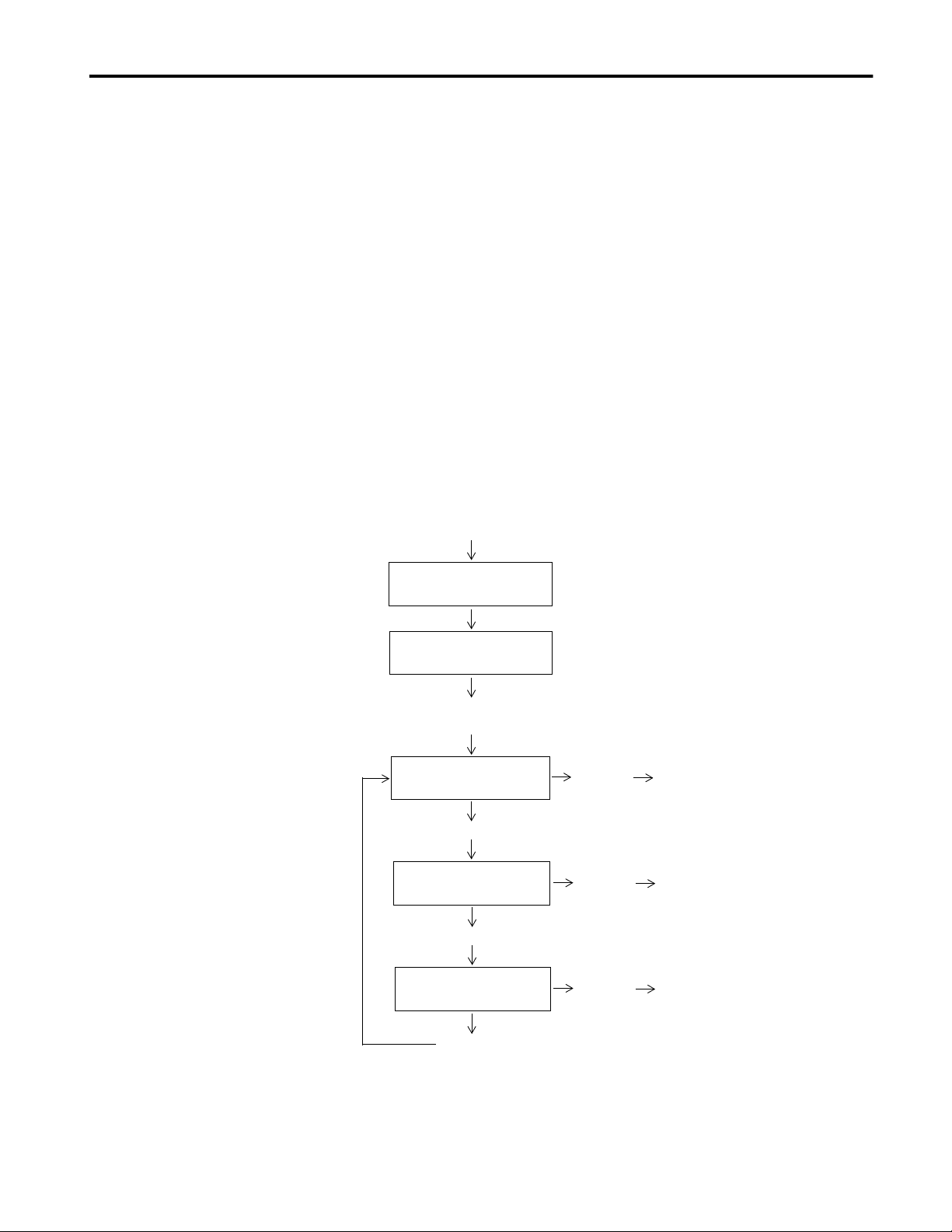
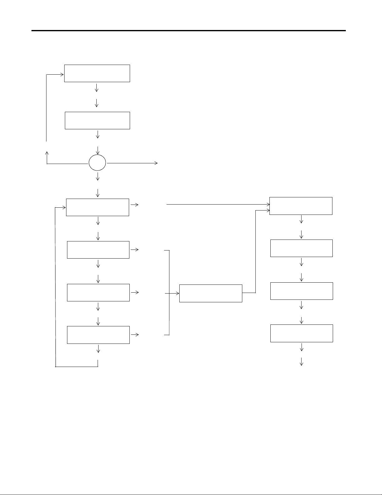
will be displayed. Refer to the following flow chart of the main menu:
Main Menu Flow Chart
Initial Power-Up
NUMERIC MODE
Displays current run mode.
0 0 0 0
Press:
[ESC][ESC][ESC]
RUN?
Press:[N]
EDIT?
Press:[N]
SPECIAL FUNC?
Press:[N]
Press:[Y]
Press:[Y]
Press:[Y]
You are now in RUN Mode.
Refer to Chapter 5.
You are now in the EDIT mode.
Refer to Chapters 3 and 4.
You are now in SPECIAL
FUNCTIONS mode. Refer
to Chapter 8.
2706-UM001A-US-P
Page 24

2-10 Getting Started
Returning to the Main Menu
Using the Control Key
Most functions (except Run) will return y ou to the main me nu when they
have been completed. However, you can return to the main menu at any
time by simply pressing the [Esc] key three consecutive times. When
executed f rom the Run or Special Functions Modes, th is will return you to
the RUN? prompt of the main menu. However, when in the Edit Mode
pressing the [Esc] key three consecutive times will return you to the Edit?
prompt of the Main Menu. You will not lose any data or messag es that ha ve
been previously entered when you press the [Esc] key.
To access certain special functions of the DL5, you may be required to use
the [Ctrl] key i n conjunc tion with a nother key. There are some variatio ns in
how you use the control key depending upon the type of terminal or
computer you are using to program the DL5. Most terminals or computers
will require you to hold down the [Ctrl] key and then press a second key.
Note: If you are using an Allen-Bradley Industrial Terminal (Catalog No.
1771-T1, -T2, -T3, or -T4), you must press and release the [Ctrl] key prior
to pressing the next key.
2706-UM001A-US-P
Page 25

Entering New Messages
Chapter 3
Chapter Objectives
Edit vs. Run Mode
In this chapter you will learn:
• How to assign attributes to a message. Message attributes define how a
message will be displayed.
• How to enter messages.
Using the DL5 is a three step process:
1. First, mes sages are entered into the DL5’s memory w hile in the edit
mode.
2. Next, the run mode, autorun message, and operating characteristics of
the serial and parallel ports are selected using the special functions
menu.
3. Finally , the DL5 is put in the run mod e. In the run mode external devices
trigger the DL5 to display stored messages or re al time variables. The
attributes selected for each message, such as flash message, scroll, etc.
will control how each message is displayed.
Selecting the Edit Mode
You can either enter a new message or edit an existing message by selecting
the edit mode. You select the edit mode by press ing t he [Y] key in r esponse
to the EDIT? prompt.
Note: To get the EDIT? prompt from the RUN mode, press [Esc] three
times, answer [N] to RUN?, and press [Retrn].
Once you have entered the edit mode, the DL5 will display a series of
prompts. Refer to the next page for a flow chart of the edit mode menu.
Important: Menu shown is for a 2 line DL5. One line displays do not have
the prompts (USE BOTH?, USE LINE 1?, USE LINE 2?, USE LEAST?).
2706-UM001A-US-P
Page 26
3-2 Entering New Messages
EDIT?
Press:[Y]
NUMBER:
Edit Mode Menu
NO ROOM!
If Memory Full
Enter Number
If Message Exists
If No Message Exists
USE BOTH?
Press:[N]
USE LINE 1?
Press:[N]
USE LINE 2?
Press:[N]
SHOWS PORTION OF EXISYING MESSAGE
To edit or change the message, use the
edit commands described in Chapter 4
Press:[Y]
Press:[Y]
Press:[Y]
SCROLL MODE?
WAIT TIME:
Enter Time
AUTO CLEAR?
Press: [Y] or [N]
AUTO REPEAT?
Press: [Y] or [N]
2706-UM001A-US-P
USE LEAST?
Press:[N]
FLASH MESG?
Press:[Y]
Press:[Y] or [N]
ENTER MESSAGE
Page 27

Entering New Messages 3-3
Specifying Message Attributes
After you have entered the edit mode and sel ected a new message n umber to
edit, you must specify t he message attributes. T he message attributes
determine how the message is displayed. The DL5 prompts for each
attribute, one at a time. You must respond to all the attribute prompts that
are displayed.
Note: If any attribute setting is changed and then the [Esc] key is pressed
three times, the changed attribute is not saved. It is necessary t o carriage
return through all attribute settings to change one of them.
Some message attributes are mutually exclusive; you can select either one,
but not both. Refer to the edit menu diagram (previous page) and the
following descriptions when specifying message attributes.
Line Selection
If you are using a single line DL5, there are no line selection prompts and
you should refer to the next section.
If you are using a two line DL5, the first message attribute that you must
specify is the line, or lines, that the message will be displayed on. There are
four options:
• 1) USE BOTH
• 2) USE LINE 1
• 3) USE LINE 2
• 4) USE LEAST
As the DL5 (two line only) displays a line selection prompt, you must
respond with either a [Y] (Yes) or [N] (No) response. If you respond to a
prompt by pressing the [Y] key followed by the [Retrn] key, the message
attribute is enter ed int o the memory of the DL5. If you re spond by p ressi ng
the [N] key followed by the [Retrn] key, the next line selection option will
be displayed. The following sections describe what effect each option has
on the displayed message.
2706-UM001A-US-P
Page 28

3-4 Entering New Messages
USE BOTH?
Selecting the USE BOTH option will au tomat i cal ly displ ay the message on
both lines of the display as a line mode message. A multi-line message will
display with the firs t li ne o f the message on the f irst line of the displ ay. The
next line of the mess age is dis played on the sec ond line of the displa y. If th e
message is longer than the number of lin es of the displ ay, the DL5 will wait
for the “wait time,” and then show the remaining lines of the message.
USE LINE1?
The USE LINE 1 option displays the message only on the first (top) line of
the display. Any messages present on the second line (if any) will remain
intact.
USE LINE2?
The USE LINE 2 option displays the mes sage only on th e second lin e of the
display. Any messages present on the first line of the display (if any) will
remain intac t.
USE LEAST?
The USE LEAST option displays the message on the l east recently u sed line
(oldest lin e of information). Any messages present o n the other li ne of the
display (if any) will remain intact.
2706-UM001A-US-P
Page 29

Entering New Messages 3-5
Selecting Line or Scroll Mode
If you are using a si ngl e l in e DL5, the first prompt you will see displayed is
the prompt for the line or scroll mode option. The prompting for line or
scroll mode will also be displayed if you are using a two line DL5 and you
did not choose the USE BOTH di spl ay opt i on. The prompt will appear li ke
this:
SCROLL MODE?
If you do not select the SCROLL MODE option, the line mode will be
automatically selected.
• Scroll Mode – A scroll mode message scrolls across the display one
character at a time. Characters enter from the right side of the display
and exit on the left.
• Line Mode – A line mode message is displayed one message block (16
characters) at a t ime. Many of the mes sages th at you cr eate may be more
than one block long. If a message is made up of more th an one messa ge
block, the DL5 will display a message block for the specified wait time
and then display the next blocks of the message.
Remember: If you are using a two line DL5 and selected the BOTH
LINES option, the line mode will be selected automat ically. You will not be
prompted for the SCROLL MODE option.
Selecting Message Wait Time
The next message attrib ute that you must select is the message w ait time.
The message wait time controls how long a message or a portion of a
message is displayed. The prompt for the message wait time appears like
this:
WAIT TIME:
You must enter a wait time value betwe en 0 and 15. The uni t of time bei ng
selected depends upon whether line or scroll mode was chosen.
• If the scroll mode has been selected, the wait time is the amount of time
that elapses before the next character is scrolled on the display. The unit
of time is in tenths of a second.
• If the line mode has been selected, the wait time is the amount of time
that a message block is displayed. The unit of time is in seconds.
2706-UM001A-US-P
Page 30

3-6 Entering New Messages
Auto Clear Option
The next prompt that you must respond to controls whether or not the
display will clear after the message is shown. The prompt appears like this:
AUTO CLEAR?
If you select the AUTO CLEAR option, the DL5 will clear the displa y after
the message has been displayed for the requested wait time. If you do not
select the AUTO CLEAR option, the last block of the message will remain
on the display until it is replaced with another message.
Auto Repeat Option
The next prompt that you must respond to allows a message to be repeated
indefinitely. The prompt for the AUTO REPEAT option appears like this:
AUTO REPEAT?
If you select the AUTO REPEAT option, the message continually
re-trigger s itself after it completes its display. If you do not selec t the
AUTO REPEAT option, the DL5 will display the message only once for
every message trigger that is received.
Note: The AUTO REPEAT function will only work with message triggers
that are in either binary or Binary Coded Decimal (BCD) format. The
function will not work when the DL5 is in the round robin or priority mode
of operation.
Flash Message Option
The last prompt determines whether or not the message flashes:
FLASH MESSAGE?
Selecting the FLASH MESSAGE option will cause the message to flash
once per second while it is being displayed. After you respond to the
FLASH MESSAGE prompt, the DL5 will display a flashing cursor. You
can now enter a message.
2706-UM001A-US-P
Page 31

Entering New Messages 3-7
Default Values for Message Attributes
Entering a Message
All of the message attribut es have def ault va lues. The fi rst time you enter a
message into a new DL5, or one whi ch has ha d its memory cleared, the DL5
specifies a default value. From then on, the default values for a new
message are the same as the previous message you entered. This feature
allows you to quickly enter a number of messages when all of the messages
have the same or similar attributes.
After you have specified all the att ri but es for a messa ge, yo u can now enter
the actual message. The DL5 stor es messages i n blocks of 16 cha racters . A
message may be more than one block in length. The number of blocks that
comprise a message is limited only by the amount of memory available.
After you have specified a message’s attributes, the DL5 will inform you
that a new message can be entered by flashing an asterisk shaped cursor:
*
Note: You can edit the message being entered, or any previously entered
message, by using the edit commands. Chapter 4 describes how to use the
edit commands.
You can now ente r you r message . As you ty pe, noti ce that the curs or moves
towards the right side of the display as characters a re entered. If the cursor
reaches the first character segment on the right, the next character that you
enter will posi ti on t he cursor back at the fi r st character segment on the left.
For example, a new message is to be entered on a two line DL5 display (16
characters in a block). The DL5 will position the cursor at the first
character position on the left:
*
If the message <Motor Starter #> is entered, the display will appear like
this:
MOTOR STARTER #*
If the number <1> is entered at the last character position, the cu rsor will
move to the first character segment on t he left . The display will appea r like
this:
*OTOR STARTER #1
2706-UM001A-US-P
Page 32

3-8 Entering New Messages
If you would enter any additional characters, the original characters would
be overwritten wit h ne w characters. If you would type in <Allen–Bradley>
the message would appear like this:
ALLEN-BRADLEY*#1
If you want to enter a message that is comprised of more than 16 characters
(one block) in len gth , you mus t press the [Ctrl] an d [J ] ke ys s imul taneously
after the first message block is entered. The DL5 will then move the cursor
to the beginning of the next block of text. For example, if you wanted to
enter the message “Feed Conveyor Is On” you would need at least two
message blocks to enter the message. First you would enter the first part of
the message <Feed Conveyor>. The DL5 will display:
FEED CONVEYOR*
You would th en select the next messa ge bl ock by pressing the [Ctr l] and [J]
keys. The DL5 will display:
*
You can now enter the second block of the message <IS ON>. The DL5
will display:
IS ON*
Note: If you press the [Ctrl] and [J] keys simultaneously at the end of a
message, a blank message block at the end of the message will be created.
The blank message block wi ll be displ ayed for th e specifi ed wait ti me. This
can cause apparent delays between messages when the display is in the run
mode. Do not type [Ctrl] [J] at the end of a message.
Now when the message is triggered, a two line DL5 will display the
message:
FEED CONVEYOR
IS ON
After you have finished entering your message , you can ret urn to the EDI T?
prompt in one of two ways:
2706-UM001A-US-P
• You can press the [Esc] key three times.
• You can press the [Ctrl] and [Q] keys to select the quit function.
Embedding Numeric Variable Data in a Message
Numeric variable data can be inserted in a message. Refer to Chapter 9
which describes how to use the variable data feature.
Page 33

Entering New Messages 3-9
Entering a Sample Message
The quickest way to learn how to use the DL5 is to enter some messages.
This section provides instructions on entering a sample message.
Note: Default values wi ll appea r on all of the mes sage a ttribute pr ompts. If
the default value is the desir ed re sponse, press the [Retrn] key to accep t the
default value. If necessary, refer back to Chapter 3 descriptions of default
values.
To enter the sample messa ge, perform th e following steps:
1. Make sure that the DL5 is displaying the following prompt:
EDIT?
Note: To get the EDIT? prompt from the RUN mode, press [Esc] three
times, answer [N] to RUN?, and press [Retrn].
2. Press the [Y] and [Retrn ] keys to ente r the edit mode. The DL5 will
display:
NUMBER: 0
3. Enter a message number that does not presently exist and then press the
[Retrn] key. The DL5 will display one of two prompts depending upon
the type of display (one or two line) that you are using.
If you are using the two line version of the DL5, the following will be
displayed:
USE BOTH?
Proceed to Step 4
If you are using the one line version of the DL5, the following will be
displayed:
SCROLL MODE?
Proceed to Step 6
4. Press the [N] and [Retrn] keys in response to the USE BOTH? prompt.
The DL5 will display:
USE LINE1?
2706-UM001A-US-P
Page 34

3-10 Entering New Messages
5. Press the [Y] and [Retrn] keys in response to the USE LINE 1? option.
The DL5 will display:
SCROLL MODE?
6. Press the [N] and [Retrn] keys in response to the SCROLL MODE?
prompt. This will select the message to be displayed in the line mode.
The DL5 will display:
WAIT TIME:
7. You want each block of the message to be displayed for three seconds.
Press the [3] and [Retrn] keys to sele ct a wait time of 3. The DL5 will
display:
AUTO CLEAR?
8. You want the message to be cleared from the display after the selected
wait time has elapsed so press the [Y] and [Retrn] keys. The DL5 will
display:
AUTO REPEAT?
9. The message that is being entered will only be displayed once per
trigger, so press the [N] and [Retrn] keys. The DL5 will display:
FLASH MESG?
10. You want the message to flash, so press the [Y] and [Retrn] keys to
select the flashing message option. The DL5 will display a flashing
cursor which indicates that a new message can be entered.
11. Enter the message <HOLDING TANK #1>. The message will appear
on the display:
HOLDING TANK#1*
12. Press the [Ctrl] and [J] keys to move the cursor to the next block of the
message. The DL5 will display the cursor at the first character position
in the second block of the message.
2706-UM001A-US-P
*
Page 35

Entering New Messages 3-11
13. Enter the second part of the message <IS FULL>. The message will
appear on the display:
IS FULL*
14. You have completed entering the message. You can see how the
message will appear when triggered by pressing the [Ctrl] and [R] keys
simultaneously. The DL5 will flash the first block of the message for
approximately three second s. And then th e DL5 will disp lay the second
block of the message for three seconds:
Note: Chapter 4 describes this and other methods of reviewing a message.
15. Return to the EDIT? prompt by pressing the [Ctrl] and [Q] keys or by
pressing the [ESC] (Escape) key 3 times.
Programming Multiple DL5s Identically
A quick method of programming multiple displays with identical messages
is to use the DL5 Series Off-line Programming Software (Catalog No.
2706-NP5). Instructions on using the software are provided with the
software package. The software can be run on IBM PC or compatible
computers with 3
1
/2 inch disk drives. This includes Allen-Bradley RAC
6000 industrial computers.
2706-UM001A-US-P
Page 36

3-12 Entering New Messages
2706-UM001A-US-P
Page 37

Reviewing and Editing Messages
Chapter 4
Chapter Objectives
Reviewing a Message
This chapter describe s how to r eview and edit e xisti ng messag es usi ng DL5
edit commands. Using a programming terminal, you can display a
previously entered message as it would normally be displayed in the run
mode. To display a message:
1. Make sure the following prompt is displayed:
EDIT?
To get the EDIT? prompt from the Run mode, press [Esc] three times,
answer [N] to RUN? and press [Retrn].
2. Press the [Y] and [Retrn ] keys to ente r the edit mode. The DL5 will
display:
NUMBER = 0
3. Enter the message number of the message you want to review and then
press the [Retrn] key. The DL5 will display the first block of the
message.
4. Press the [Ctrl] and [R] keys simultaneously. The DL5 will then display
the message as it would appear with all its selected attributes.
5. After displaying the mes sage, the DL5 will return to showing a portion
of the message. The DL5 is still in the edi t mode. You can now edit the
message using the techniques described in this chapter or you can exit
the edit mode by pressing the [Ctrl] and [Q] keys simultaneously. The
DL5 returns to the EDIT? prompt.
2706-UM001A-US-P
Page 38

4-2 Reviewing and Editing Messages
Displaying the Amount of Memory Remaining
You can command the DL5 to display the amount of memory (message
blocks) remaining for new messages or additions to existing messages. To
display the number of message blocks remaining, press the [Ctrl] and [F]
keys simultaneously whil e the dis pla y is in the edit mode showing par t of a
message. The DL5 will display:
FREE SPACE 0020
The number that is displayed is the number of message blocks remaining.
Each message block can contain 16 characters.
After two seconds, the DL5 will automatically return to the same block of
the message that was bein g displayed prior to the [Ctrl] [F] function.
The table below li sts the commands availabl e for your us e. Use this ta ble as
a quick reference for the DL5 commands.
DL5 Edit Commands
Keys
Pressed
Command Function
[Ctrl] [A] Allows access to previously entered message attributes
so they can be reviewed or changed.
[Ctrl] [C] Centers a message on the display.
[Ctrl] [D] Deletes a single message block.
[Ctrl] [E] Erases an entire message.
[Ctrl] [F] Shows the number of free message blocks remaining.
[Ctrl] [H] Moves the cursor one character position to the left.
[Ctrl] [I] Inserts a message block between two previously entered
message blocks.
[Ctrl] [J] Creates a new message block after previously entered
message blocks or moves the cursor one message block
towards the end of the message.
[Ctrl] [K] Moves the cursor one message block towards the
beginning of the message.
[Ctrl] [L] Moves the cursor one character position to the right.
[Ctrl] [Q] Exits the edit mode with save.
[Ctrl] [R] Runs a message in the edit mode.
[Ctrl] [V] Embeds a single digit variable in a message. Displays
the data without leading zeros.
[Ctrl] [X] Imbeds a single digit variable in a message with leading
zeros.
2706-UM001A-US-P
Page 39

Reviewing and Editing Messages 4-3
Selecting a Message to Edit
Moving the Cursor
To edit a previously entered message, perform the following steps:
1. Make sure the following prompt is displayed.
EDIT?
Note: T o get to the EDIT? prompt from the Run Mode, press [Esc] three
times, answer [N] to RUN? and press [Retrn].
2. Press the [Y] and [Retrn ] keys to ente r the edit mode. The DL5 will
display:
NUMBER: 0
3. Enter the message number of the messag e tha t you want to edit and then
press the [Retrn] key.
The DL5 will then display a portion of the message you want to edit. You
can now edit the message using the edit commands.
All editing activity occurs at the cursor position. To edit a message, you
must first position the cursor at the characters that are to be changed. The
following commands are used to position the cursor.
Forespace [Ctrl] [L]
This command moves the cursor one character position to the right. You
select the forespace command by pressing the [Ctrl] and [L] keys. If the
cursor is already at the last character position, the cursor will move to the
first character position on the left side of the display.
Note: Many types of terminals have a forward arrow key. This key will
often generate the [Ctrl] [L] command.
Backspace [Ctrl] [H]
This command moves the cursor one character position to the left. You
select the backspace command by pressing the [Ctrl] and [H] keys. If the
cursor is already at the firs t charact er posi tion in the message th e cursor wil l
move to the last character position.
Note: Many types of ter minals have a back arrow or a [BACKSPACE] key.
Both of these keys will often generate the [Ctrl] [H] command.
Forward One Message Block [Ctrl] [J]
This command moves the cursor one message block towards the end of the
message. If the cursor is al ready at the la st mess age bl ock in a message , th e
command will create a new message block directly after the previous
message block. You select the forward one message block command by
pressing the [Ctrl] and [J] keys.
Note: Do not type [Ctrl] [J] after the fi nal message bl ock has been ente red.
A blank message block will be cr eated and displ ayed as p art of t he messag e.
2706-UM001A-US-P
Page 40

4-4 Reviewing and Editing Messages
Back One Message Block [Ctrl] [K]
This command moves the cursor one message block towards the beginning
of the message. If the curs or is already a t the first message block in the
message, the DL5 will ignore the command. You select the back one
message block command by pressing the [Ctrl] and [K] keys.
Deleting a Character
Deleting a Message Block
You can delet e a c haract er by typi ng in a new char acte r dir ectl y ov er t he old
character. If you want to delete a character and replace it with a blank
space, use th e [SPACE] key.
You can delete an entire message block by pressing the [SPACE] key
repeatedly until all of the characters are replaced with blank spaces.
However, the message block will not be deleted from memory.
You can delete an entire block of a message by pressing the [Ctrl] and [D]
keys. The delete message block command will delete all 16 characters in a
message block. After you delete a message blo ck, the DL5 will the n display
one of three items:
• If you deleted the first message block in a multiple block message, the
DL5 will display the second block of the message.
• If you deleted any mess age block, other than the f ir st message block in a
multiple block message, the DL5 will display the previous message
block.
• If you deleted the only message block in a single block message, the
entire message is deleted and the DL5 will display the EDIT? prompt.
For example, assume that the DL5 contains the following message which is
stored in three separate message blocks:
PRESSURE IN
RESERVOIR TANK IS NORMAL
Assume the cursor is positioned at the firs t ch aracter in the second message
block. The DL5 display will appear like this:
*ESERVOIR TANK
If the [Ctrl] and [D] keys are now pressed , the messag e block RESERVOIR
TANK will be deleted. The messa ge now cont ains j ust t wo message blocks :
PRESSURE IN
IS NORMAL
The DL5 displays the message block that was preceding the deleted
message block:
*RESSURE IN
2706-UM001A-US-P
Page 41

Reviewing and Editing Messages 4-5
Inserting a Message Block
You can insert a message block (if free message blocks are available)
between two previously existing message blocks by pressing the [Ctrl] and
[I] keys. The new message block is inserted after the message block that
was being displayed when the insert message block command was pressed.
For example, assume that the DL5 contains the fo ll owin g message which is
stored in two separate message blocks:
CONVEYOR BELT
HAS STOPPED
Assume that the cursor is positioned at the first character in the first
message block. The DL5 display will appear like this:
*ONVEYOR BELT
Note: The cursor does not have to be in the first character position.
If the [Ctrl] and [I] keys are now pressed, a new message block will be
created after the first message block. The DL5 will display:
*
If the message <IN SHIPPING> is entere d in the new message block, the
message would now contain three message blocks:
CONVEYOR BELT HAS STOPPEDIN SHIPPING
Deleting an Entire Message
You can quickly delete an entire message from memory by pressing the
[Ctrl] and [E] keys. The command will erase all of the message blocks
contained in a message.
For example, assume that the DL5 contains the fo ll owin g message which is
stored in two message blocks:
HOPPER #2 IS EMPTY
Assume that the cursor is positioned at the first character position in the
second message block. The DL5 display will appear like this:
*S EMPTY
If the [Ctrl] and [E] keys are now pressed , the DL5 will first display:
SURE?
Next the [Y] and [Retrn] keys must be pressed to confirm that the message
is to be dele ted. The DL5 will delete the message and then displ ay:
EDIT?
2706-UM001A-US-P
Page 42

4-6 Reviewing and Editing Messages
Editing Message Attributes
To edit the previously entered attributes of a message, perform the
following steps:
1. Make sure the following prompt is displayed:
EDIT?
Note: T o get to the EDIT? prompt from the Run Mode, press [Esc] three
times, answer [N] to RUN?, and press [Retrn].
2. Press the [Y] and [Retrn ] keys to ente r the edit mode. The DL5 will
display:
NUMBER: 0
3. Enter the message number of the message you want to edit and then
press the [Retrn] key. The DL5 will display a portion of the message.
4. Press the [ Ctrl] and [A] keys.
– If you are using a one line display, the DL5 will display:
SCROLL MODE?
– If you are using a two line display, the DL5 will display:
USE BOTH?
5. You can now change message attributes by entering new [Y] or [N]
responses to the message attribute prompts and then pressing the [Retrn]
key . Or you can keep the origi nal att ribut es by pres sing th e [Retrn ] key.
The attribute prompts will appear in the same sequence as when they
were first entered.
2706-UM001A-US-P
Page 43

Run Mode
Chapter 5
Chapter Objectives
Entering Run Mode
This chapter describes how to enter and exit run mode. You will also learn
how the DL5 operates while in run mode.
Run Mode - Parallel Operation
To enter run mode for parallel operation:
1. Make sure the Serial Trigger / Configure DIP switch (SW1-1) is in the
DOWN (Configure) position.
Configure
Not Used
DOWN
12
2. Check that the following prompt is displayed:
RUN?
Note: To get the RUN? prompt fro m th e Spec ial Fun cti ons Mode, press
[Esc] three times. From t he Edit Mode, it is also nece ss ary to answer no
to Edit? and Special Functions?
SW1
3. Press the [Y] and [Retrn] keys to enter the run mode. The DL5 will
display either a blank screen or a selected autorun message. Chapter 8
describes the autorun message and how the autorun message is selected.
The DL5 is now in the run mode and will display any messages that are
triggered by the control system.
To exit the parallel run mode:
Press the [Esc] key three times. The DL5 displays the following prompt
when run mode is terminated:
RUN?
2706-UM001A-US-P
Page 44

5-2 Run Mode
Run Mode - Serial Operation
To enter the serial triggering run mode:
Move the DIP switch (SW1-1) to the UP (serial trigger) position.
Serial Trigger
Not Used
UP
SW1
12
This immediately switches the DL5 from the edit to run mode. The
operation of the seria l port changes from prog ra mming to ser ial mes sage
triggering.
Note: Any message e dits or menu entries are ter minated when the DIP
switch position is changed.
After entering the serial trigger mode, the standard startup screens are
displayed followed by the autorun mess age. The DL5 will the n interpret any
serial data as a message trigger command.
To exit the serial triggering run mode:
Move the DIP switch (SW1-1) to the Down (configure) position.
Configure
Not Used
DOWN
12
SW1
This switches the DL5 from the run to edit mode. The operation of the
serial port changes from serial message tri gger ing to programming. The
following is displayed after exiting the serial triggering mode:
RUN?
With the DIP switch in the Configure position, any serial data is
interpreted as a menu or edit command.
2706-UM001A-US-P
Page 45

Run Mode 5-3
Description of Run Mode
In the run mode, the DL5 wait s for the host to send messag e tr ig gers and/or
variable data. The DL5 receives message tri ggers and v ariable d ata throu gh
either the parallel or serial port. The serial and parallel ports cannot be
active at the same time. The Serial Trigger/Configure DIP switch
determines the active port (Serial Trigger position = serial port, Configure
position = parallel port). When a message trigger is received, the DL5
searches its memory for the selected message, inserts any imbedded
variables, and then displays the message.
If another message trigge r is sent to the DL5 before the fi rst mes sage’s wait
time has expired, the DL5 stores the message trigger in a message buffer.
The capacity of the message buffer is one message. Refer to the following
example which shows how the message buffer operates.
1. The host controller sen ds a message trigger for mes sage number 27 to
the DL5. The DL5 removes the message trigger from the message buffer
and displays message number 27.
Control System
Message Trigger
#27 Sent
DL5
Message Buffer
27
Message #27
is displayed
2. While the DL5 is displaying message number 27, the DL5 receives a
message trigger for message number 18. The message trigger is stored
in the message buffer.
Control System
Message Trigger
#18 Sent
DL5
Message Buffer
18
Message #27
is still displayed; its wait
time has not expired.
3. The DL5 receives an additional message tr igger for messa ge number 45,
while message number 27 is still displayed. Since the message buffer
already contains a messag e tr ig ger, the trig ger for mes sage number 45 is
ignored.
Control System
Message Trigger
#45 Sent
DL5
Message Buffer
18
Message #45 Ignored
Buffer is Full
Message #27
is displayed
2706-UM001A-US-P
Page 46

5-4 Run Mode
4. After the DL5 completes the display of message number 27, the DL5
removes the message trigger for message number 18 from the message
buffer and then displa ys message number 18. The message buffer is now
ready to accept another message number.
Control System
DL5
Message Buffer
Message #18
is displayed
Note: While in the priority or round robin modes of operation, the DL5
does not store message triggers in the buffer.
2706-UM001A-US-P
Page 47

Using the Serial Port
Chapter 6
Chapter Objectives
The DL5 has a full duplexed RS-232 serial port which is used for:
• communication with the offline programmer and f or programming input
from a “dumb” ASCII terminal.
• serial triggering of messages
The operation of the serial port is determined by the Serial Trigger/
Configure DIP switch on the back of the DL5 see page 2-2. The RS-232
serial port is a 9-pin male D-shell connector located at the rear of the DL5.
A drawing of the DL5’s connector is provided below:
DTR
RXD COM
4
9
8
7
CTS RI
53
RS-232
DCD
1
6
DSR
TXD
2
RTS
The RS-232 port operates at baud rates of 300, 1200 and 9600 baud. The
rate is user selectable through the Special Functions Menu or the Offline
Programmer. The default baud rate of the DL5 is 9600 baud.
Programming Cables
Cables are available to connect various programming devices. The
following table lists the cable to use with various terminals or computers:
Serial Cable
Catalog Number
2706-NC12 Personal computers with 25-pin female communication port
2706-NC13 Personal computers with 9-pin female communication port
2706-NC14 Allen-Bradley RAC 6000 industrial computers (PC/XT).
2706-NC15 Allen-Bradley Industrial Terminals T1 through T4 (25-pin male
Description
connector. DEC VT52, VT100, or VT101 terminals. Allen-Bradley
RAC 6000 industrial computers.
connector (IBM AT and compatible). Allen-Bradley RAC 6000
industrial computers.
connector).
See Appendix B for cable diagrams and descriptions.
2706-UM001A-US-P
Page 48

6-2 Using the Serial Port
RS-232 Signals
The DL5’s RS-232 port uses T ransmit Data sig nal, Receiv e Data s ignal, and
Signal Common. The Clear To Send, Data Carrier Detect, and Data Set
Ready pins are tied high (+12V) by the DL5, allowing direct connection of
the DL5 to terminals or computers requiring a request to send signal. No
jumpers at the terminal or computer connector should be required.
Pin Number Signal Name (Signal Mnemonic) Signal Type
1 Data Carrier (DCD) Output
2 Transmit (TXD) Output
3 Receive Data (RXD) Input
4 Data Terminal Ready (DTR) Input
5 Signal Common (COM) -6 Data Set Ready (DSR) Output
7 Request to Send (RTS) Input
8 Clear to Send (CTS) Output
9 Ring Indicator (RI) Output
Data Carrier Detect - Pin 1 Indicates that a continuous frequency
“capable of being modulated or impressed with a signal” is being received.
The DL5 sets this line high.
T ransmit Data - Pin 2 Sends out the serialized data fr om the DL5 (e.g., t he
serial data is on this pin).
Received Data - Pin 3 This signal also carries serial data. However, the
serialized data is sent from another device as input to the DL5.
Data T erminal Ready - Pin 4 Indicates the t ra nsmi ssion device (termina l)
is connected, powered up, and r eady t o send data. The DL5 i gnores thi s lin e.
Signal Common - Pin 5 The ground reference for all other signals.
Data Set Ready - Pin 6 Indicates that a communications device is
connected, powered up, and ready for data transmission. The DL5 sets this
line high.
Request to Send - Pin 7 Signal from the terminal device requesting the
communication device to send data. This typically turns on the data carrier.
The DL5 ignores this line.
Clear to Send - Pin 8 This signal indicates to the transmitting device that it
can start sending data. The DL5 sets this line hig h.
Ring Indicator - Pin 9 This signal indicates that each device is physically
connected to adjacent devices. The DL5 sets this line high.
2706-UM001A-US-P
Page 49

Using the Serial Port 6-3
Serial Port Protocol
When the DL5 is set to be triggered through the serial port, use the
following protocols to trigger messages and display variable data:
Message Trigger [Ctrl][T]
Use the CTRL-T command to trigger messages while the DL5 is in the
binary and BCD modes. The message number and address are decimal
values. The command has the following format:
CTRL-T
Message
Number
\
Backslash
where:
– Message Number is a decimal value in the range 1-999
– DL5 Address is a decimal value in the range of 0-127
For example, to trigger Message #123 on a DL5 with an address of 10, the
following string would be sent:
ASCII ^T 1 2 3 \ 1 0 ^M
HEX 14 31 32 33 5C 31 30 0D
DL5
Address
Carriage
Return
Note: If you need to trigger messages (Round Robin and Numeric modes),
with a PLC that does not support unsigned integers, refer to the application
note in Appendix D
Note: If the DL5 is in serial trigger mode and you attempt to download
messages using the offline programming software, data corresponding to a
message trigger command will be executed.
2706-UM001A-US-P
Page 50

6-4 Using the Serial Port
Variable Data [CTRL][V]
Use the CTRL-V command to send data for display in Binary, BCD,
Numeric, Priority, and Round Robin modes. All values are decimal values.
The command has the following format :
\
CTRL-V
Variable
Data
Backslash
Variable
Position
where:
– Variable Data is 1 to 5 ASCII digits (0-65535)
– Variable Position is single ASCII digit (value is ignored)
– DL5 Address is 1 to 3 ASCII digits (0-127)
For example, to send a value of 500 to a DL5 with an address of 99, the
following string would be sent:
ASCII ^V500\1\99^M
HEX 16 35 30 30 5C 31 5C 39 39 0D
\
Backslash
DL5
Address
Carriage
Return
Note: In Binary mode, variable data can be in the range 0 to 16,383. In
BCD mode, variable data must be in the range 0 to 3999. In Round Robin
and Numeric modes, variable data can be in the range of 0 to 65535.
2706-UM001A-US-P
Page 51

Using the Parallel Port
!
Chapter 7
Chapter Objectives
Description of the Parallel Port
This chapter provides:
• A description of the parallel port.
• Data format requirements for parallel input.
• Descriptions and examples of message triggering.
• Parallel port interface examples.
Note: This chapter describes how you can use the parallel port to trigger
messages. If you requ ire i nformat ion on ho w to inpu t va riabl e data , refe r to
Chapter 9.
ATTENTION: The DL5 only has single direction
communications (receives data, cannot send data). Do not use
the DL5 for critical display applications. Single direction
communications does not provide verification that messages
sent by the control s yst em have be en rec eived a nd dis played by
the DL5.
You can use the parallel port of the DL5 to trigger messages and to input
variable data. The parallel port is located on the back of the DL5. The
parallel port terminals (TB1) are labeled as shown on the next page.
2706-UM001A-US-P
Page 52

7-2 Using the Parallel Port
Parallel Port Connections (TB1)
Parallel Port
1
2
1
TB1TB2
D0D1D2D3D4D5D6D7D8D9D10
2
SW1
PARALLEL PORT 5-24 VDC INPUT
TB2
1 COM
2 12-24V DC Input
D11
D12
D13
1 Serial Trigger / Configure
2 Not Used
D14
D15
PD
SW1
RS-232
• Terminals D0 through D15 are for message number and data input.
• T erm inal PD i s for t he enabl ing or disabl ing of the par allel port. I f PD is
tied high, the port is disabled and the DL5 will ignore data on data lines
D0-D15. I f PD is low, the port is enable d and the DL5 will read and
respond to data on data lines D0-D15. As long as PD is controlled
separately, using PD will allow multiple DL5’s to be connected to one
set of outputs (multiplexed).
• The input voltages for terminals D0 through D15 and PD can vary from
5 to 24 volts DC. The figure below shows a circuit diagram of an input
terminal.
Parallel Port Input Circuit
DATA
D0-D15
3.3K
COM
100K
3.3K
+5 VDC
LATCH
Latch Closes When the
”PD” Terminal On the
DL5 Parallel Port Is
Open or Low
2706-UM001A-US-P
Page 53

Using the Parallel Port 7-3
Selecting BCD or Binary Data Format
The parallel port will accept data and message triggers in either a binary or
Binary Coded Decimal (BCD) format or in non-coded discrete form which
allows the DL5 to easily replace pilot lights as described in Chap ter 10.
Each numbering system, binary or BCD, has its own merits. Your choice
will often be based upon the format used by your controller. Both the
binary and BCD numbering systems allow you to address all 999 possible
message numbers but vastly different maximum variable values. The
maximum variable value that can be input in binary or BCD run modes is
shown below:
Run Mode Maximum Message # Maximum Variable Value
BCD 999 3,999
Binary 999 16,383
You must select which format best suits your needs and then select the run
mode as described in Chapter 8.
2706-UM001A-US-P
Page 54

7-4 Using the Parallel Port
Using Binary Data Input
In the binary (Run) mode, the DL5 interprets data on terminals D0 through
D13 as binary data. Terminals D14 and D15 are the strobe lines. Terminal
D0 represents the least significant digit and D13 represents the most
significant digit . A data line may eith er be at ground leve l, which represent s
a binary value of 0, or a data line may have a voltage present, which
represents a binary value of 1.
The convention of having a voltage represent a value of 1 and ground
representing a value of 0, is known as positive binary logic (high tr ue logic).
The opposite conventi on is known as n egative binary l ogic (lo w true lo gic).
You can set the DL5 to accept eit her positive or negative logic (high or lo w
true), refer to Chapter 8. The following table shows the value of each data
line. Selecting the binary data run mode is explained in Chapter 8.
Binary Values of the Data Lines
Data Line Value When On
(True)
D0 1 D8 256
D1 2 D9 512
D2 4 D10 1,024
D3 8 D11 2,048
Data Line Value When On
(True)
D4 16 D12 4,096
D5 32 D13 8,192
D6 64 D14 Strobe Line
D7 128 D15 Strobe Line
The table below shows the control functions of the strobe lines:
D14 D15 Function
High or Low High Indicates that binary value on D0 through D13 represents a
message number.
High Low Indicates that binary value on D0 through D13 represents
variable (numeric) data.
Low Low Binary value on D0 through D13 is ignored.
Example: Assume that the following logic lev el s (posit ive log ic) appe ar on
the data lin es.
Data Line: D0 D1 D2 D3 D4 D5 D6 D7 D8 D9 D10 D11 D12 D13 D14 D15
Logic Level: 1000100100001010
Value: 1000160012800004,096 0 0 0
2706-UM001A-US-P
Adding the values of the individual data lines provides the value being
entered, in this example 4,241. Since strobe line D14 is high (voltage
present) and D15 is low (ground level), this value is interpreted as variable
data.
Page 55

Using the Parallel Port 7-5
Using BCD Data Input
The fourteen data lines can also be used to input BCD formatted data. The
BCD numbering system use s a gr oup of four data li nes to represent a sin gle
decimal digit. The t able below sh ows t he valu e of ea ch data line. Sel ecti ng
the BCD run mode is explained in Chapter 8.
BCD Values of the Data Lines
Data Line Value When On
(True)
D0 1 D8 100
D1 2 D9 200
D2 4 D10 400
D3 8 D11 800
D4 10 D12 1,000
D5 20 D13 2,000
D6 40 D14 Strobe Line
D7 80 D15 Strobe Line
Data Line Value When On
(True)
Control functions of the strobe lines are the same for BCD data input as for
binary data input.
For example, assume the following logic (positive logic) levels appear on
the data lin es.
Data Line: D0 D1 D2 D3 D4 D5 D6 D7 D8 D9 D10 D11 D12 D13 D14 D15
Logic Level: 1010001010001010
Value: 1040004001000001,000 0 0 0
Adding the values of the individual data lines provides the value being
entered, in this example 1,145. Again, D14 is high (voltage present) and
D15 is low (ground level), so this number is interpreted as variable data.
2706-UM001A-US-P
Page 56

7-6 Using the Parallel Port
Logic Levels
The DL5’s parallel port accepts DC inputs of 0-24 volts. These input
voltages can be used to t rigger messages or transf er variab le (numeric) data.
The DL5 interprets the voltages that are pres ent on the data lines as either a
“High” or “Low” condition. There is also a third state which should be
avoided, an in between or indeterminate state. The indeterminate state
occurs when the input voltage is between the “High” voltage range and the
“Low” voltage range. The voltage ranges that the DL5 interprets as either
“High” or “Low” values depends on whether positive or negative binary
logic has been selected.
The table below lists the voltage ranges and their logic values.
Positive Logic
Level
High (True) Low (True) 3.5 to 24V DC 0.9 to 3.5V DC
Low (False0 High (False) 0 to 0.9V DC 0.9 to 3.5V DC
Negative Logic
Level
Recognized
Voltage Range
Indeterminate
Voltage Range
2706-UM001A-US-P
Page 57

Using the Parallel Port 7-7
Using the Numeric (Run) Mode
In this mode, the DL5 interprets inputs into the parallel port only as BCD
numeric data and immedi ately dis plays the BCD nu mber. Only line 1 of the
DL5 is used. Inputs to the first twelve terminals (D0 through D11) are
always interpreted as three BCD digits. Inputs to the last four terminals
(D12 through D15) are interpreted as a fourth BCD digit (if the input is a
valid BCD code), or as a special instruction code (if the input is not a valid
BCD code). The speci al i nstruction code all ows you to define a desti nat ion
on the DL5 display for the three BCD numbers on data lines D0 through
D11. This allows a number as large as 15 digits, two 6 digit numbers, or
three 3-digit numbers to be displayed on the DL5. The table below defines
the special instruction codes of D12 through D15.
Numeric Mode Functions
D15 D14 D13 D12 Value Function
00000Interprets input as a fourth BCD digit of
the value given
00011
00102
01003
4
01015
01106
01117
10008
10019
1010-Displays the three BCD digits (from
inputs D0-D11) in the first 3 (leftmost)
character positions.
1011-Displays the three BCD digits (from
inputs D0-D11) in the second character
position from the left.
1100-Displays the three BCD digits (from
inputs D0-D11) in the third character
position from the left.
1101-Displays the three BCD digits (from
inputs D0-D11) in the fourth character
position from the left.
1110-Displays the three BCD digits (from
inputs D0-D11) in the fifth character
position from the left.
1111-Clears the display and sets decimal
point.
2706-UM001A-US-P
Page 58

7-8 Using the Parallel Port
Example:
You want to display the following number and decimal point in the DL5:
456123
You would send data to the parallel port in the following sequence:
1.
D15 D14 D13 D12 D11 D10 D9 D8 D7 D6 D5 D4 D3 D2 D1 D0
1 1 1 1 0 0 0 0 0 0 0 0 0 1 1 0
Clears the display and
sets the decimal point.
And positions the decimal point 6
places from the right of the display.
2.
D15 D14 D13 D12 D11 D10 D9 D8 D7 D6 D5 D4 D3 D2 D1 D0
1 1 0 0 0 0 0 1 0 0 1 0 0 0 1 1
Directs BCD digits to
third 3 character position.
And sends the BCD number 123
3.
D15 D14 D13 D12 D11 D10 D9 D8 D7 D6 D5 D4 D3 D2 D1 D0
1 1 0 1 0 1 0 0 0 1 0 1 0 1 1 0
Directs BCD digits to
fourth 3 character position.
And sends the BCD number 456
If an invalid BCD digit i s re ceived, the correspondin g character position on
the display will be blan k. If the number s etting th e decimal poi nt is zero, no
decimal point is displayed. When the decimal point is used, it takes one
character position on the display as shown in the examples.
You can update the numbers on the display without clearing the display or
resetting all digits. That is, to change three digits of a number, you send
only those three digits, along with the appropriate special instruction code;
the remaining digits are left unchanged.
2706-UM001A-US-P
Note: If you are changing all the numbers on the display, you should clear
the entire di splay.
Page 59

Using the Parallel Port 7-9
Example:
You want to change the number in the previous example from 123.456 to
123.789999:
789123 999
You would send data to the parallel port in the following sequence:
1.
D15 D14 D13 D12 D11 D10 D9 D8 D7 D6 D5 D4 D3 D2 D1 D0
1 1 0 1 0 1 1 1 1 0 0 0 1 0 0 1
Directs BCD digits to
overwrite the fourth 3
character position.
And sends the BCD number 789.
2.
D15 D14 D13 D12 D11 D10 D9 D8 D7 D6 D5 D4 D3 D2 D1 D0
1 1 0 0 1 0 0 1 1 0 0 1 1 0 0 1
Directs BCD digits to
third 3 character position.
And sends the BCD number 999.
Note: No leading zero blanking is performed in the numeric mode.
however , individu al digit s for D0 t hrough D1 1 can be bla nked by setting the
input for that digit to a non-BCD value (greater than 9).
2706-UM001A-US-P
Page 60

7-10 Using the Parallel Port
Numeric Mode and Autorun Message
Using a two line DL5 , the numer ic mode can display an autoru n message o n
line two in addition to the numeric data on line one. The autorun message is
selected as described in Chapter 8. It should be programmed to appear on
line two with autoclear set to NO. Each time the display enters the run
mode or is powered up, the autorun message will appear on line two. The
numeric data being sent will appear on line one.
Example:
7231
4
568 9
P
P
SD
PRES
E
ETEM
This autorun message serves as a “legend” or “label” for the numeric
variables.
When using the numeric mode, data must be held on the parallel port for
110 milliseconds (see page 7-13).
2706-UM001A-US-P
Page 61

Using the Parallel Port 7-11
Using DC Outputs to Trigger the
DL5
There are two types of DC outputs:
• Hard contact outputs
Hard contact outputs contain mechanically operated contacts. Examples
of hard contact outputs include relays, push buttons, limit switches, and
contact output modules such as Allen-Bradley’s PLC module (Catalog
No. 1771-OW) or SLC module (Catal og No. 1746- OW16). Any cont act
that does not have a leakage current while in the OFF state can be
considered a hard contact device.
• Solid-state DC outputs
Solid-state outputs do no t ha ve any mechanically operate d cont ac ts . All
switching functions in a solid-state contact are done electronically.
Examples are:
PLC Modules
– Catalog No. 1771-OB or -OBD
SLC Modules
– Catalog No. 1746-OV8, -OV16, -OV32
– Catalog No. 1746-OB8, -OB16, -OB32
– Catalog No. 1746-OG16
The figure below illustrates how DC output s can be used to tr i gger t he DL5.
Connecting DC Outputs to the DL5 Data Lines
DL5 Terminals
D0 D1 D2 D3 D15
Controlling
Device
Contacts
TB2-1
COM
-
DC Power
Supply
+
2706-UM001A-US-P
Page 62

7-12 Using the Parallel Port
Determining Current Requirements For DC Outputs
Y o u must check to make sur e that the DC outputs sup plying the pa rallel port
can supply enough current to handle the requirements of the DL5’s parallel
port. The table below lists the current requirements for one DL5 parallel
port input.
Parallel Port Typical Requirements for DC Outputs
5V DC Input 12V DC Input 24V DC Input
3.0 mA 7.3 mA 14.6 mA
T o determine the total current requirements of the parallel port, multiply the
number of inputs being used by the value found in the above table. For
example: Assume that you are using 24 VDC outputs:
Each input will draw a peak current of 14.6 milliamperes. If you are
using all sixteen inputs, your output source must be able to provide 234
milliamperes of current (16 x 14.6 mA = 234 mA).
The table below lists the voltage and current requirements, per DL5 input,
for various Allen-Bradley output devices.
Voltage and Typical Current Requirements Per DL5 Input
Output Type Input Voltage Input Current
1771-OB 12 or 24V DC 7.3 or 14.6 mA
1771-OBD 12 or 24V DC 7.3 or 14.6 mA
1771-OW 24V DC 14.6 mA
1746-OB 12 or 24V DC 7.3 or 14.6 mA
1746-OV 12 or 24V DC 7.3 or 14.6 mA
1746-OG 5V DC 3.0 mA
2706-UM001A-US-P
Page 63

Using the Parallel Port 7-13
!
Parallel Port Power Supply Requirements
Timing Requirements of the Parallel Port
The DL5 parallel ports require an input voltage source between 5-24 VDC
with peak-to-peak noise and ripple less than 5% of the input voltage.
A TTENTION: To avoid ground loops, the same power supply
that powers the displ ay mus t be use d to supply the parallel por t.
The DL5 reads (scans) the data lines periodically . You must ensure that the
data is present on the data lines long enough to be read.
Note: Refer to Chapter 9 for a description of the timing requirements for
messages with variable data.
In order to ensure that the data is rea d, the data must remain on the data
lines for at l eas t 110 milliseconds. After eac h scan the DL5 saves a copy of
the data that was read. If the next scan reads the same data, the data is
ignored. This feature prevents multiple triggering of the same message.
The figure below illustrates a typical message trigger sequence. Message
#1 is triggered and then message #10 is trigger ed. In this ex ample, th e DL5
is set to accept BCD formatted codes (message or variable).
BCD Message Number Timing Example
110 ms
D0
D1
D2
D3
D4
D5
D6
D7
D8
D9
D10
D11
D12
D13
D14
D15
t0
t1
110 ms
t2
t3
2706-UM001A-US-P
Page 64

7-14 Using the Parallel Port
The following are descriptions of what occurs during each of the four
timing intervals (t0, t1, t2, and t3):
During t0, the trigger for message No. 1 and strobe line D15 to indicate
message number are placed on the data lines.
During t1, the message trigger and strobe are kept unchange d a t the parallel
port for a minimum of 110 milliseconds.
During t2, the trigger for message No. 10 and strobe line D15 to indicate
message number are placed on the data lines, and the trigger for message
number 1 is removed.
During t3, the message trigger and strobe are kept unchange d a t th e parallel
port for 110 milliseconds.
2706-UM001A-US-P
Page 65

Special Functions
Chapter 8
Chapter Objectives
Introducing the Special Functions Menu
In this chapter you will learn how to:
• set the electrical characteristics and operating mode of the parallel port
• use debug mode
• clear memory
• set the autorun message number
The special functions menu i s accessed fr om the main menu. You select the
special functions by pressing the [Y] key then the [Retrn] key at the
SPECIAL FUNC? prompt. You will then be shown a sequence of prompts
for the five special functions. To enter a special function you must press the
[Y] key and then the [Retrn] key. If you do not want to enter a particular
special function pr ess the [Retrn ] key ([N] is the def ault) ; the DL5 wil l then
display the next prompt. The five special functions are:
• SET PORT
• SET RUN MODE
• DEBUG
• CLEAR MEMORY
• SET AUTORUN
2706-UM001A-US-P
Page 66

8-2 Special Functions
The figure below show s a flow chart o f the Special Functions menu.
SPECIAL
FUNC?
SET PORT?N
N
SET RUN
MODE?N
N
DEBUG?N
N
N
Y
HIGH TRUE?Y
Y/N
BAUD:
ENTER <3> for 300
<12> for 1200
<96> for 9600
[Retrn]
ADDRESS: xxx
Y
RUN MODE:
ENTER <PR> for Priority
<RR> for Round Robin
<BN> for Binary
<BC> for BCD
<NM> for Numeric
[Retrn]
Y
DEBUGGER
[ESC] three times
CLEAR
MEMORY?N
N
SET
AUTORUN?N
N
Y
Y
SURE?N
Y
POSITIVE?N
Y
MEMORY LOST
NUMBER= xxx
N
N
ENTER <Message Number>
[Return]
RUN?
2706-UM001A-US-P
Page 67

Special Functions 8-3
Entering the Special Functions Menu
To enter the special functio ns menu, follow the steps below.
1.
Make sure the RUN? prompt is displayed:
RUN?
Note: T o get t he RUN? promp t from the run mode , press [Esc] t hree time s.
From Edit mode it is also necessary to answer [N] to EDIT? and SPECIAL
FUNC?.
2. Press the [N] and [Retrn] keys. The DL5 displays:
EDIT?
3. Press the [N] and [Retrn] keys. The DL5 displays
SPECIAL FUNC?
4. Press the [Y] and [Retrn] keys to enter the Special Functions menu. The
DL5 displays:
SET PORT?N
The set port prompt is the first special function. To enter the set port
function press the [Y] and [Retrn] keys. To enter one of the other four
special functions, press the [Retrn] key until the special function that you
want is displayed ([N] is the default).
2706-UM001A-US-P
Page 68

8-4 Special Functions
SET PORT Special Function
The set port function allows you to set the fo ll owing parallel and serial port
parameters.
• positive or negative logic (high true or low true) of the parallel port
• baud rate (300, 1200, or 9600) of the RS-232 serial port
• address of the DL5 (for serial triggering)
You enter the set port function by pressing the [Y] and [Retrn] keys in
response to the SET PORT? prompt. After selecting the set port function,
the first prompt that the DL5 displays:
HIGH TRUE?Y
If you answer [Y] (the default) to the high true input option, the DL5 will
interpret the voltages on the data lines as positive logic signals. If you
answer [N] to the high true option, negative logic is selected.
If positive logic is selected:
• A voltage on a data li ne is interpreted as an ON ( lo gic 1 / true) conditi on.
• The absence of voltage on a data line is interpreted as an OFF (logic 0 /
false) condition.
If negative logic is select ed:
• A voltage on a data line is interpreted as an OFF (logic 0 / false)
condition.
• The absence of voltage on a data line is interpreted as an ON (logic 1 /
true) condition.
Note: If possible, we recommend that you confi gure your system so tha t in
a normal operating condition as few as possible input lines have a voltage
applied to them. This will keep the DL5 at a lower operating temperature
and extend its life.
The next prompt that you must respond to is:
Baud (3, 12, 96):96
The present baud ra te is t he defaul t valu e. Enter t he desir ed baud rat e: 3 for
300, 12 for 1200, and 96 for 9600. The baud rate changes immediately.
The DL5 is shipped with a baud rate of 9600 baud.
Once the baud rate is changed, the baud rate of your programming device
must also be changed to match the DL5 before programming/editing of the
DL5 can continue. After specifying a baud rate, the current address is
displayed:
ADDRESS: xxx
2706-UM001A-US-P
Page 69

Special Functions 8-5
After you provide an address, press [Retrn] and the DL5 will display the
beginning RUN? prompt.
Run Mode Special Functions
The run mode determines how the DL5 will interpret the data present on the
parallel port. The DL5 is shipped in the numeric mode.
SET RUN MODE?N
To change or view the run mode selection, respond to the SET RUN
MODE? prompt by pressing [ Y], the n [R etrn] .The fo llowin g ap pears on the
display:
RUN MODE=xx
Where xx is the mnemonic for the last
entered run mode.
Respond to the RUN MODE = prompt with a two letter mnemonic. The
mnemonic that you pro vid e dete rmines whic h Run Mod e is u sed. The ta ble
below lists the run modes of the DL5’s parallel port. After you provide a
run mode mnemonic the DL5 will return to the RUN? prompt. Once a run
mode is selected, the DL5 will ente r that run mode on default when power is
cycled off, then on. If an invalid mnemonic is entered, the previously
selected run mode mnemonic is displayed.
Run Mode Mnemonic Description
Priority PR Chapter 10
Round Robin RR Chapter 10
Binary BN Chapter 7
BCD BC Chapter 7
Numeric NM Chapter 7
2706-UM001A-US-P
Page 70

8-6 Special Functions
Debug Special Function
The Debug special function is very valuable if you are having difficulty
triggering messages properly in the run mode. The debug function allows
you to visually determine whether or not a voltage is applied to a DL5 data
line. If you respond to the DEBUG? prompt by pre ssing the [ Y] and [ Retrn]
keys, the DL5 displays the status of the data lines:
0000010000010011
The debug mode display consists of sixteen characters (ones and zeros).
This display represents the condition of the sixteen data lines. The
character on the far left represents data line D15 and the character on the
right represents data line D0. If you have set the parallel port for negative
logic, a voltage on a d at a l ine will be represented by a 0. If posi ti ve logic is
selected, a voltage on a data line will be represented by a 1. For example,
assume that a debug mode display appears like this:
0000100001100100
If positive logic has been selected, the above display would indicate that
there is a voltage present on data lines D2, D5, D6, and D11. If negative
logic has been selected, the above display would indicate that there is a
voltage present on data lines D0, D1, D3, D4, D7, D8, D9,D10, D12, D13,
D14, and D15.
To exit the debug mode, press the [Esc] key three times.
2706-UM001A-US-P
Page 71

Special Functions 8-7
CLEAR MEMORY Special Function
The clear memory special function clears all messages from the DL5
EEPROM memory. To clear the DL5 memory perform the following steps:
1. Press the [Y] and [Retrn] keys in response to the CLEAR MEMORY?
prompt. The DL5 displays:
SURE?N
2. Press the [Y] and [Retrn] keys in response to the SURE? prompt. The
DL5 displays:
POSITIVE?N
3. Press the [Y] and [Retrn] keys in response to the POSITIVE? prompt.
The DL5 displays:
MEMORY LOST
While Memory Lost is displayed, the DL5 is actually clearing the
EEPROM. Hitting any key, such as [Escape], will not speed up this
function. Depending on the amount of t he memory used and the size of the
EEPROM (2 or 8 Kbytes), it could take up to 30 seconds before Memory
Lost is cleared and the display shows:
SET AUTORUN Special Function
RUN?
The set autorun function allows you to set the autorun message number. If
the power to the DL5 is interrupted while in the run mode, the DL5 will
automatically enter the run mode when the power is reapplied. The autorun
message is the firs t mes sa g e t hat th e DL5 displays when the DL5 enter s t he
run mode. After the autorun message is display ed the DL5 resumes normal
run mode operation. If you pr ess the [ Y] and [Ret rn] k eys in re sponse to the
SET AUTORUN? prompt, the DL5 displays:
NUMBER: X
Note: X is the value of the last message number edited.
You can now enter the message number of the message that you want
displayed when the DL5 is powered up in the autorun mode. Enter the
autorun message number (0–999) and then press the [ Retrn] key. If no
autorun message is desired, enter a 0 (zero). After entering an autorun
message number, the DL5 displays the RUN? prompt.
2706-UM001A-US-P
Page 72

8-8 Special Functions
2706-UM001A-US-P
Page 73

Using the Variable Data Feature
Chapter 9
Chapter Objectives
Variable Data Limits
In this chapter you will learn how to insert up to five digits of variable data
in a message. You will learn:
• how to program messages with embedded variables.
• the format of the variable data.
• timing requirements for the transfer of variable data.
The DL5 can accept message triggers and variable data using either the
parallel or serial port.
Serial Port - The serial port accepts CTRL-T commands for message
triggers an d CTRL-V commands for va riable data. T he range for variable
data sent to the serial port is (0-65535). Serial commands always use
decimal numeric values (binary and BCD distinctions do not apply).
Parallel Port - The parallel port can be set to accept either binary or BCD
formatted data for message triggers and variable data input.
Whichever format (BCD or binary) you select will be used for both the
variable data and message triggers. You cannot input message triggers in
one format and variable data in another format. The table below shows the
largest varia ble and me ssage number that can b e entered for both bi nary and
BCD formats.
Maximum Ranges for Variable Data sent to Parallel Port
Scan
Mode
BN Binary 999 16,383
BC BCD 999 3,999
You cannot enter negative numbers for variable data.
Input Format for Message
and Variable Data
Maximum
Message Number
Variable Value
2706-UM001A-US-P
Largest
Page 74

9-2 Using the Variable Data Feature
Creating Messages with Embedded Variable Data
You can progra m variable data within a messa ge while the messa ge is being
created in the edit mode. To embed one digit of a variable, press the [Ctrl]
key and [V] keys simultaneously at the location in the message where the
variable digit is to appear. The [C tr l] and [V] command will i nse rt a caret ^
in the message. For example: Assume that the following message is being
entered:
7+(&2817,6
To embed a single digit of a variable, press the [Ctrl] and [V] keys. The
DL5 will display the location of the variable in the message:
7+(&2817,6A
Up to five single digit variables (only four variables allowed with BCD
format) can be embedded in a message. The embedded variables do not
have to be in consecutive positions in a message. For example: The
following message has been entered, the DL5 is set to accept BCD
formatted data:
AA2)AA%$'
If the number 1050 is transferred to the DL5 and the message is triggered,
the DL5 will display:
2)%$'
2706-UM001A-US-P
Page 75

Using the Variable Data Feature 9-3
Embedding a Decimal Point
You can display numbers which have decimal points. The decimal point is
inserted just li ke any oth er char acter and it t akes up one full ch ara cter space.
Insert a decimal point before or after the [CTRL] [V] by typing [.]. For
example, the following steps would be required to create the message
“SPEED IS . FPS”.
1. Enter the following message:
63((',6
2. Enter the first variable digit by pressing the [Ctrl] and [V] keys:
3. Press the [.] key to ente r the decim al point . Notice that the decimal point
requires a character position. The decimal point becomes a part of the
variable.
4. Then enter the second variable digit by pressing [Ctrl] and [V] keys.
5. Finish entering the message by typing [F] [P] [S].
Note: Use [CTRL][X] to imbed variable digits with leading zeros.
[CTRL][V] imbeds variable digits without leading zeros.
Sending Variable Data Through the Serial Port
Use the CTRL-V command to send data for display in Binary, BCD,
Numeric, Priority, and Round Robin modes. All values are decimal values.
The command has the following format :
CTRL-V
Variable
Data
\
Backslash
Variable
Position
\
Backslash
DL5
Address
Carriage
Return
where:
– Variable Data is 1 to 5 ASCII digits (0-65535)
– Variable Position is single ASCII digit (value is ignored)
– DL5 Address is 1 to 3 ASCII digits (0-127)
For example, to send a value of 500 to a DL5 with an address of 99, the
following string would be sent:
ASCII ^V500\1\99^M
HEX 10 35 30 30 5C 31 5C 39 39 0D
Note: In Binary mode, variable data can be in the range 0 to 16,383. In
BCD mode, variable data must be in the range 0 to 3999. In Round Robin.
Priority and Numeric modes, variable data can be in the range of 0 to
65535.
Note: The CTRL-V command in Priority, Round Robin and Numeric
modes triggers messages not variables.
2706-UM001A-US-P
Page 76

9-4 Using the Variable Data Feature
Parallel Port Strobe and Data Bits
The DL5 uses the sixt een data lin es (D0 thr ough D15) to input b oth varia ble
data and message t ri gge rs . Data lines D0 thro ugh D13 t ra nsf er the fourteen
data bits and data lines D14 and D15 are the two strobe lines.
The strobe lines indicate whether the data on the data lines is a message
number or variable data. There are four possible combinations of the two
strobe lines. The table below lists the four strobe combinations and the
DL5’s interpretation of the strobe commands.
Strobe Commands
Strobe Command Strobe Line, Data Line D14 Strobe Line, Data Line D15
Ignore Data Lines OFF OFF
Variable Data ON OFF
Message Number OFF ON
Message Number ON ON
Notice that if data line D15 is ON, the DL5 will interpre t the data on the
data lines as a message number r egardl ess of the condit ion of data li ne D14.
2706-UM001A-US-P
Page 77

Using the Variable Data Feature 9-5
Parallel Port Timing Requirements
The following is an example of how the strobe commands are used. In this
example, message #12 , which contains a two digit variable, is triggered.
The message that was entered for message #12 appears like this:
63((',6AA)36
First the controller sends the variable value (BCD format) for message #12
to the DL5. Then the controller sends the trigger for message #12. The
figure below illustrates the timing of th e data transfer and message trigger.
BCD Message Number Timing Example
D0
D1
D2
D3
D4
D5
D6
D7
D8
D9
D10
D11
D12
D13
D14
D15
110 ms
t0 t1 t2 t3
110 ms
The following describes what occurs during each of the timing intervals.
t0- During t0 the variable dat a 35 and strob e line D14 to in dic ate var iable
data is set on the data lines.
t1- During t1 the value of 35 and strobe line D14 are maintained for 110
milliseconds.
t2- During t2 the message number 12 is placed on the data lines, and
D15 is set to indicate a message number. D14 is reset.
t3- During t3 the message number 12 and strobe line D15 are main tai ned
for 110 milli sec onds.
The timing example (previous page) shows the minimum hold time (110
milliseconds) that is required for each step of the variable data
transfer and message trigger.
2706-UM001A-US-P
Page 78

9-6 Using the Variable Data Feature
Note: The PLC program scan time must be added to the hold time. If the
scan time is 10 milliseconds, then the minimum data hold time in the PLC
program should be 120 milliseconds to make sure data is held at the DL5
for the minimum 110 milliseconds.
To summarize the timing requirements:
• Data and strobes are set all at once.
• Once data and strobe lines are set, they must remain unchanged for a
minimum of 110 milliseconds.
• The total cycle time for a variable dat a transfer and message trigger is a
minimum of 220 milliseconds. A cycle time of 220 millise cond s all ows
you to update a variable approximately 4 times per second.
2706-UM001A-US-P
Page 79

Using the Variable Data Feature 9-7
Suggestions on Using the Variable Data Feature
Message attribute settings are important to the proper functioning of the
variable da ta feature. Refer to Chapte r 3 for review of message attributes.
The following message attribute settings are recommended.
Line Selection recommendations:
• Do not use the scroll mode when variables are within a message. The
message should appear as one or two lines.
• Limit each message to one screen (16 characters if a one line message,
32 characters if a two lin e message).
Wait Time recommendation:
• Set the wait time of a variable message to zero to allow for the fastest
update of the variable.
Auto Clear recommendation:
• Set auto clear to NO.
Auto Repeat recommendation:
• Do not use the auto repeat display option for messages that contain
variable data. If the auto repeat display option is selected, the DL5 will
resample the data lines for variable data each time the specified message
wait time has expired.
Your controller cannot send variable data for a new message trigger until
the auto repeat message is halted. Y ou can halt the display of an auto repeat
message by triggering a programmed blank message number.
Note: A blank message is one which has been created but has no
displayable characters. Its attributes could be Wait Time Zero, Auto Clear
No, and Auto Repeat No.
For example, the following describes a triggering sequence that occurs
using an auto repeat message with four variable digits. The message being
triggered is:
AA2)AA%$'
This message has a wait time of zero, and no auto clear.
1. First, the controller sends the variable data “1050”.
2. Next, the controller sends the trigger for the message.
2706-UM001A-US-P
Page 80

9-8 Using the Variable Data Feature
3. The DL5 wi ll then display the message:
2)%$'
4. The controller then transmits a new variable “2040”.
5. The DL5 wi ll then display the message with the new variable data:
2)%$'
6. To enter and display a different message with embedded variable data,
the controller must first trigger a programmed blank message to stop
display of the variable message.
7. The controller can now send the variable for the new message.
8. The controller can then send the message number for the new message
Updating a Variable Frequently – If your application requires that the
variable data within a message be updated frequently, you should program
the message with the following attributes:
• A wait time of zero.
• The auto clear function is not selected.
These message attribute settings will make it possible to update variable
data at the fastest rate (once every 220 milliseconds). This assumes a
normal sequence of events to enter variables and message numbers:
• Send a variable. (110 milliseconds)
• Send a message number. (110 milliseconds)
• Send a variable. (110 milliseconds)
• Send a message number, etc. (110 milliseconds)
Note: PLC program scan time must be added to the 110 millisecond data
hold time in the PLC program to assure that data i s on the DL5 parallel po rt
for 110 milli sec onds.
2706-UM001A-US-P
Page 81

Chapter 10
Using the DL5 Parallel Port to Replace Pilot
Lights
Chapter Objectives
Description of Input Modes
This chapter shows you how to replace up to 16 pilot lights with a single
DL5. Descriptions of both the prior ity and rou nd robin ope rating modes ar e
provided.
The DL5 has 2 modes of operation which allow you to replace pilot lights:
• Round Robin input mode - while in the round robi n mode of operati on,
the DL5 will look at the sixteen data lines as individual inputs. Each of
the inputs is like the input wire to an individual pilot light. When a data
line to the DL5 is triggered, a message corresponding to that data line is
displayed.
• Priority input mode - the priority input mode is similar to the round
robin input mode except that each of the data lines is assigned a priority
in relation to the other data lines.
Note: These pilot li ght opera ting modes do not s upport va riable da ta withi n
a message.
Pilot lights are typically used in one of two ways:
1. Pilot lights can be used as status indicators. For example, a pilot light
can inform an operator that a motor is on or off.
2. Pilot lights can also be used as diagnostic indicators. For example, a
pilot light can inform an o perator that an overload relay is tripped.
2706-UM001A-US-P
Page 82

10-2 Using the DL5 Parallel Port to Replace Pilot Lights
Round Robin Mode
In the Round Robin mode of operation you can specify both an OFF state
message and an ON state message for each input. Messages are scanned in
sequence beginning with data line D0 and ending with data line D15. If
several inputs are ON, the DL5 displays the messages in the sequence that
they are scanned. The following table lists the message numbers that are
assigned to each of the sixteen inputs.
Data Line No. ON Message No. OFF Message No.
D0 1 17
D1 2 18
D2 3 19
D3 4 20
D4 5 21
D5 6 22
D6 7 23
D7 8 24
D8 9 25
D9 10 26
D10 11 27
D11 12 28
D12 13 29
D13 14 30
D14 15 31
D15 16 32
Notice that each of the sixteen data lines listed in the table has both an ON
message number and an OFF message nu mber assigned. You do not have to
program both an OFF and an ON message for ea ch input . You can program
only an ON or only an OFF state message; or no message at all.
2706-UM001A-US-P
Page 83

Using the DL5 Parallel Port to Replace Pilot Lights 10-3
When the DL5 is placed in the round robin mode of operation, the DL5
begins by looking at the first data line D0. One of three events will occur
depending upon the con dition of the data line and whether or not a message
is programmed:
• If data line D0 is in an ON state, the DL 5 will display message #1 (if
message #1 is programmed). Message #1 is the ON state message for
data line D0.
• If data line D0 is in the OFF state, the DL5 will display message #17 (if
message #17 is programmed ). Message #17 is the OFF state message f or
data line D0.
• If no message exists, the DL5 will ignore data line D0.
The DL5, will then look at the second data line, D1. One of three ev ents
will occur dependin g upon the condition of the dat a l ine and whe th er or not
a message is programmed.
• If data line D1 is in an ON state, the DL 5 will display message #2 (if
message #2 is programmed). Message #2 is the ON state message for
data line D1.
• If data line D1 is in the OFF state, the DL5 will display message #18 (if
message #18 is programmed ). Message #18 is the OFF state message f or
data line D1.
• If no message exists, the DL5 ignores data line D1.
The DL5 then looks at the remainder of the data lines, D2 through D15.
After data line D15 is scanned, the DL5 will then start the sequence over
again beginning with data line D0. If only one data line is on, the display
will not clear befor e retrig gering the message a ssociated wi th that dat a line.
If no data lines are on , the dis play i s clea red after the mess age wait time ha s
expired.
Note: If a data line is turned ON then OFF before the DL5 scans it, it will
not be remembered as being ON by the DL5. The DL5 will not look for
additional ON terminals until it is done executing a message it has
recognized as ON.
2706-UM001A-US-P
Page 84

10-4 Using the DL5 Parallel Port to Replace Pilot Lights
Priority Mode
In the priority mode of opera tion you can only spe cify an ON state me ssage
for each input. If several inputs are ON, only the highest priority message
will be displayed. The following table lists the message numbers that are
assigned to each of the sixteen inputs.
Data Line No. ON Message No. OFF Message No.
D0 1 1 (Highest)
D1 2 2
D2 3 3
D3 4 4
D4 5 5
D5 6 6
D6 7 7
D7 8 8
D8 9 9
D9 10 10
D10 11 11
D11 12 12
D12 13 13
D13 14 14
D14 15 15
D15 16 16 (Lowest)
If programmed, message #17 is displayed if no data lines are ON.
Notice that each of the sixteen data lines listed in the table above only has
an ON message number assigned. You do not have to program a message
for each of the inputs; if an in put does not have a messag e prog rammed , the
DL5 will ignore the input. Each input has an assigned priority level. Data
line D0 has priority over data line D1, data line D1 has priority over data
line D2, data line D3 has priority over data line D4, etc. The DL5 displays
the message number that corresponds to the highest priority data line. For
example: If data lines D1, D4, and D7 are in an ON condit ion, the DL5 will
display message #2 (message #2 is the message assigned to data line D1).
Message #2 will continue to be repeated for as long as data li ne D1 rema ins
in an ON state; unless da ta line D0 changes to an ON state. If data line D0
changes to an ON state , it ove rr ides data line D1 because dat a l ine D0 has a
higher priority. The DL5 then displays message #1 (message #1 is the
message assigned to data line D0). If only one input is ON and that input
goes OFF, the display will automatically clear.
2706-UM001A-US-P
In addition to the sixteen messages associated with data lines D0 through
D15, there is a message #17. Message #17 is only displayed when none of
the data lines is in an ON condition.
Page 85

Using the DL5 Parallel Port to Replace Pilot Lights 10-5
Using the Round Robin Input Mode
If you want to operate the DL5 in the Round Robin mode of operation,
perform the following steps:
1. You must decide whether the DL5 will be set for positive or negative
logic. If positive logic is selected, voltage on a data line will represent
an ON condition. If negative logic is selected, the absence of voltage on
a data line represents an ON condition.
2. Select the round robin mode of operation as described in Chapter 8
3. Place the DL5 in the edit mode and program messages for the message
numbers that are associated with each input. The following message
attribute settings are suggested to provide the clearest round robin
functionality.
– Line 1, line 2, or both lines can be selected as desired.
– Scroll message can be selected as desired.
– Wait time can be set as desired and will control how long a message is
displayed before the DL5 goes on to the next message.
– Select Auto Clear, to clear the screen after each message. Otherwise
you might have a portion of a two line message remaini ng on the DL5
when a sing le line message follows.
Note: The DL5 will always clear the display when no inputs are on.
– Auto Repeat has no function in Round Robin mode.
– Flash Message can be selected as desired.
4. Place the DL5 in run mode.
2706-UM001A-US-P
Page 86

10-6 Using the DL5 Parallel Port to Replace Pilot Lights
Using Priority Input Mode
In Priority Input mode, only one message (the highest priority) can be on
the screen at a time.
If you want to operate the DL5 in priority mode, follow these steps:
1. You must decide whether the DL5 will be set for positive or negative
logic. If positive logic is selected, voltage on a data line will represent
an ON condition. If negative logic is selected, the absence of voltage on
a data line repres ents an ON c ondition. Ch apter 8 d escribes how you can
set the DL5 for either positive or negative logic.
2. Select the round robin mode of operation as described in Chapter 8.
3. Place the DL5 in the edit mode and program messages for the message
numbers that are associat ed with each inpu t. Chapte r 3 descr ibes ho w to
enter messages.
The following message attribute settings are suggested to provide the
clearest round robin functionality.
– Line 1, line 2, or both lines can be selected as desired.
– Scroll message can be selected as desired.
– Wait time can be set as desired and will control how long a message is
displayed before the DL5 goes on to the next message.
– Select Auto Clear, to clear the screen after each message. Otherwise
you might have a portion of a two line message remaini ng on the DL5
when a single line message follows.
Note: The DL5 always clears the display when no inputs are on.
– Auto Repeat has no function in Round Robin mode.
– Flash Message can be selected as desired.
4. Place the DL5 in run mode.
2706-UM001A-US-P
Page 87

Chapter 11
Using the DL5 to Replace BCD Displays and
Lookup Tables
Chapter Objectives
Replacing a BCD Fault Code Display
This chapter provides instructions on how to replace a 2 or 3-digit BCD
numeric display and any associated lookup tables with a single DL5.
The first step in replacing a BCD display is to determine if your DL5 has
enough memory to store all of the BCD codes. Typically a BCD display is
used in conjunction with a lookup table. If a code is displayed on the BCD
display, an opera to r will refer to a lookup table to determ ine t he meaning of
the code. If you are going to replace a BCD display and lookup table with a
DL5 you must make sure that the DL5 can store the meanings of all the
codes listed in the BCD lo okup tabl e. The DL5 can st ore 94 or 387 mess age
blocks depending on memory size (2K or 8K).
Note: Memory capacity is given in the number of message blocks that are
available. Some of the messages that you enter may require more than one
message block. A message block is one line of 16 characters.
After you have determined that the DL5 has sufficient capacity to store the
messages, perform the following steps:
1. You must set the DL5 to accept positive logic. If positive logic is
selected, voltage on a data line will represent an ON condition.
2. Set the DL5 to accept BCD input as described in Chapter 8.
3. Place the DL5 in the edit mode and program messages for the message
numbers that were previously displayed on the BCD display.
4. Tie strobe line D15 high to indicate message numbers by wiring it to a
5-24 VDC source.
5. Place the DL5 in the run mode.
2706-UM001A-US-P
Page 88

11-2 Using the DL5 to Replace BCD Displays and Lookup Tables
2706-UM001A-US-P
Page 89

Installation Instructions
!
!
Chapter 12
Chapter Objectives
Grounding
Wire Routing
In this chapter you will learn how to:
• Mount the DL5 in a panel or an enclosure.
• How to wire the DL5 to your control system.
Grounding is an important safety mea sure in in stallin g the DL5. As with all
solid-state systems, grounding also helps limit the effect of noise due to
electromagnetic interference (EMI). The DL5 mounting studs and nuts
(once tightened) connect the DL5 chassis to your equipment ground.
Note: The common terminal on the back of the DL5 is not equipment
ground. The common te rminal must be c onnect ed sepa rate ly t o your power
supply common.
Careful wire routing helps reduce electrical noise. Route all DL5 wiring
separately and away from all high voltage wiring (115VAC or above). Do
not run the DL5 wiring in the same conduit as any AC power wiring (115
VAC and above). When high voltage wiring and the DL5 wiring must
cross, their intersection should be perpendicular. In addition, the data line
wiring (D0-D15) should be routed away from transformers, solenoids, or
other devices that are known to generate electrical noise (EMI).
ATTENTION: Fusing the DL5 power wiring is import ant to
protect both the power supply and the DL5 from damage
should a short circuit occur. Since the DL5 has no fuses, we
recommend you use external fusing.
ATTENTION: You must connect the common lead of the
power source to the DL5. Failure to connect the common lead
may result in electrical shock. In addition, the common lead
protects the DL5 from electrical noise. Do not apply power to
the display until all wiring to the DL5 is completed.
2706-UM001A-US-P
Page 90

12-2 Installation Instructions
!
!
ATTENTION: To avoid ground loops and damage to the
equipment, the same p ower suppl y must be us ed for t he parall el
port and the power input to the DL5.
Mounting the DL5
You can mount the DL5 in a custom panel or enclosure.
When the DL5 is properly installed, the faceplate of the DL5 provides a
NEMA Type 12/13 and 4 enclosure integrity rating. To mount the DL5:
1. Punch and drill the appropriat e mounting hole s in the encl osure or pan el.
The following page shows the mounting dimensions of the DL5.
ATTENTION: DO NOT install the DL5 until all cutouts and
holes are completed. Metal filings may fall into and damage
the DL5.
2. Remove the four nuts from the mounting studs on the DL5’s face plate.
3. Install the display in the panel cutout and tighten the four nuts on the
mounting studs to a torque of 9 lb-in (1.02Nm).
2706-UM001A-US-P
Page 91

DL5 Mounting Dimensions in Inches (Millimeters)
Installation Instructions 12-3
FRONT
6.25 (158.8)
TOP
5.25 (133.4)
DATALINER
3.12
(79.3)
4.31(108.0) Max
Depending On
Panel Thickness
PANEL
0.22(5.6) Max
PANEL CUTOUT DIMENSIONS
5.75 (146.1)
5.38 (136.7)
2.88 (73.2)
2.25
(57.2)
Cutout
1.31
(33.3)
1.12
(28.6)
0.171 (4.3 mm)
Diameter Hole
4 Places
2706-UM001A-US-P
Page 92

12-4 Installation Instructions
!
Power Supply Requirement
ATTENTION: To avoid system ground loops and damage to
equipment, the same p ower suppl y must be us ed for t he parall el
port and the power input to the DL5.
The power supply used to power the DL5 and to supply the parallel port
data lines must meet the following specifications:
Supply Voltage: 12-24 VDC
Ripple: 5% of input voltage p-p (max.)
Noise: 5% of input voltage p-p (max.)
Supply Current
12 VDC 250 mA operating (300 mA inrush)
24 VDC 125 mA operating (300 mA inrush)
Parallel Port: (17 inputs maximum)
5 VDC 3.0 mA per input (typical)
12 VDC 7.3 mA per input (typical)
24 VDC 14.6 mA per input (typical)
Fusing: External fusing should be provided.
After the DL5 has been mounted, the necessary wiring can be connected to
the DL5. The following figure illustrates the terminal connections located
on the back of the DL5. Perform the following steps to connect wiring to
the DL5.
2706-UM001A-US-P
Page 93

Wiring the DL5 (Rear View)
Installation Instructions 12-5
TB2 Terminals 1-2
DL5 Power Terminals
12-24V DC Required
COMMON
12-24V DC
Switch 1 (SW-1)
Enables Serial Trigger / Configure
UP = Serial Trigger
DOWN = Configure
Not Used
1
2
1
TB1TB2
D0D1D2D3D4D5D6D7D8D9D10
2
PARALLEL PORT 5-24 VDC INPUT
TB1 Terminals
Parallel Port Input Data lines
Accept 5-24V DC
SW1
DOWN
12
DC Line Terminals
1 COM
2 12-24V DC Input
Configure
Not Used
TB2
D11
D12
D13
1 Serial Trigger/Configure
2 Not Used
D14
D15
PD
Terminal PD
Disables the Parallel Port
Terminal Accepts 5-24V DC
Serial Trigger
Not Used
UP
12
SW1
RS-232
RS-232 Port
Allows Connection to
Programming Terminal
or Computer and serial
communications with
PLC / SLC
RS-485 Multidrop Connections
COM
CHA
CHB
RS-485 Black Box Converter
(Model LD-485A-MP)
DL5
RS-232
Pin 2
Pin 3
Pin 5
Pin 2
Pin 7
Pin 3
RS-232 IN
RxB
RxA
TxB
TxA
RS-485
Shield
to Ground
RS-485 Black Box Converter Notes:
1. Set RTS/CTS delay time to 5 milliseconds.
2. Set switch S2 to the unterminated position.
3. If the RS-485 Driver Enable is set to Enable When Data is Received on the RS-232 port (Jumper W15 is in the B-C position),
set the Disable Timeout Delay (Jumper W17) to 100 msec or greater when communicating at lower Baud rates (300 or 1200 Baud).
2706-UM001A-US-P
Page 94

12-6 Installation Instructions
!
!
!
Power / Parallel Port Wiring
The parallel port data inputs and power inputs are wired by means of
pull-off ter m ina l st ri ps. These strips may be removed and wired separ at ely,
and then inserted onto the unit after the unit is mounted in the enclosure.
1. Connect a 12-24 VDC input voltage source to the DL5 power terminals
(TB2).
• The hot lead of the power source is connected to terminal #2 (12-24
VDC).
• The common lead of the power source is connected to terminal #1.
ATTENTION: There are no fuses contained in the DL5.
Therefore, we recommend tha t exte rnal f using be us ed to avo id
any possible damage to the DL5 or power supply.
ATTENTION: You must connect the common lead of the
power source to the DL5. Failure to connect the common lead
may result in electrical shock. In addition, the common lead
protects the DL5 from electrical noise. Do not apply power to
the display until all wiring to the DL5 is completed.
2. Connect the communication lines from the host programmable
controller, computer, or other controlling devices to the DL5 parallel or
serial ports.
ATTENTION: The common for the parallel port should be
the same common as the power source.
Note: To ensure proper connection through the pull-off terminals, strain
relief must be provided for all DL5 wiring.
2706-UM001A-US-P
Page 95

Chapter 13
Maintenance and Troubleshooting
Troubleshooting Chart
This chapter provides general maintenance and troubleshooting
instructions. A troubleshooting chart is provided to aid you in determining
the cause of a malfunction.
The table below lists the most common operating problems and possible
solutions. The DL5 does not contain user serviceable components.
Troubleshooting Chart
Problem Probable Causes Corrective Action(s) Reference
DL5 does not power up. 1. Loose or incorrect wiring to DL5
(TB2)
2. Blown power supply fuse.
3. Bad power supply
Programming terminal or computer
does not communicate with the DL5.
1. Baud rate of terminal or
computer does not match the
DL5.
2. Incorrect connection cable.
1. Check for proper wiring and that
connector TB2 is properly
inserted.
2. Check external power supply
fuse.
3. Check power supply output.
1. Set Baud rate of terminal to
match the DL5.
2. Check that the proper cable is
being used.
Chapter 12
N/A
12
2, 8
6, Appendix B
2706-UM001A-US-P
Page 96

13-2 Maintenance and Troubleshooting
Problem Probable Causes Corrective Action(s) Reference
Messages do not trigger properly.
Messages are not displayed when
triggered.
“INVALID MSG#” is displayed on DL5
1. Parallel port voltages are not per
DL5 requirements.
2. Serial Trigger / Configure DIP
switch SW1-1 is not in correct
position.
3. Message number is not present
on the DL5 data lines for the
required hold time.
4. Strobe lines are not being set to
indicate message numbers.
5. Incorrect Run mode is selected.
6. Messages being triggered do not
exist (INVALID MSG#)
1. Check the voltage range of your
controller outputs.
2. Check the setting of DIP switch
SW1-1
3. Configure your control systems
so message numbers are held on
the data lines for a minimum of
110 milliseconds.
4. Configure your control system to
set the data lines to indicate
message number.
5. Set Run mode to match the type
of output used by the control
7, 12
2
7
7, 8
8
system (Binary, BCD, etc.).
6. Program the messages into the
3
DL5.
Note: In all cases use the debug
(Chapter 8) to verify that the
mode
inputs to the DL5 parallel port are
correct.
Messages with embedded variables
are not displayed properly.
Delays exist between messages (the
screen is blank).
1. Strobe lines are incorrectly set.
2. Data and strobe line timing
requirements are not met.
3. Incorrect Run mode is selected
4. Ctrl-V characters incorrectly
embedded in message.
1. Blank message block created at
the end of a message due to
typing Control J at end of edit.
1. Configure the control system to
set the strobe lines for the type
of data (message number or
variable data) being sent.
2. Configure the control system to
meet timing requirements.
3. Set the Run Mode to match the
type of outputs used by the
control system.
4. Check for proper insertion of
Ctrl-V characters.
Edit the message and remove any
blank message blocks.
9
9
8
9
3
2706-UM001A-US-P
Page 97

Specifications
Chapter 14
Electrical
Input Power Requirements
Current: 250 mA maximum steady-state @ 12 VDC input.
Power: 3 Watts maximum
Ripple: 5% of input voltage p-p maximum
Noise: 5% of input voltage p-p maximum
Voltage
12-24 VDC
Operating and Inrush Currents
12 VDC 250 mA oper. (300 mA inrush)
24 VDC 125 mA oper. (300 mA inrush)
Parallel Port
16 data input lines (14 data lines and 2 strobe lines for BCD and Binary
modes) and 1 parallel port select input.
Parallel Port Data Input Voltage
5 to 24 volts DC
Voltage Levels for Positive Logic
High:
Recognized 3.5 to 24.0 VDC
Indeterminate 0.9 to 3.5 VDC
Low:
Recognized 0.0 to 0.9 VDC
Indeterminate 0.9 to 3.5 VDC
Voltage Levels For Negative Logic
Low:
Recognized 3.5 to 24.0 VDC
Indeterminate 0.9 to 3.5 VDC
High:
Recognized 0.0 to 0.9 VDC
Indeterminate 0.9 to 3.5 VDC
2706-UM001A-US-P
Page 98

14-2 Specifications
Data Input Current (typical per input)
5 VDC 3.0 mA
12 VDC 7.3 mA
24 VDC 14.6 mA
Serial Programming Port
RS-232
Memory
• 2K EEPROM - 94 message blocks
• 8K EEPROM - 387 message blocks
Environmental
Operating Temperature
32°F to 122°F (0° to 50°C)
Storing Temperature
-40° to 185°F (-40° to 85°C)
Humidity
5% to 95% - No condensation
NEMA
NEMA Type 12, 13 and 4 (indoor use only) panel mount.
Noise Susceptibility
Passes ICS 2–230 showering arc noise immunity test.
Approximate Weight
1.5 lbs. (0.68 kg.)
Approximate Shipping Weight
2706-UM001A-US-P
3.0 lbs. (1.35 kg.)
U.L. Listing
Class 1, Division 2, Groups A, B, C, D Hazardous Location
CSA Certification
Class 1, Division 2, Groups A, B, C, D Hazardous Location
Page 99

Specifications 14-3
Display Characteristics
Programming
Character Height
One line display - .262 in. (6.65 mm.)
Two line display - .216 in. (5.5 mm.)
Character Set
Alphanumeric - upper case only
Characters Per Line
16
Character Type
Vacuum fluorescent, 14 segment (plus “,” and “.”) characters
Approximate Viewing Distance
10 feet (3 meters)
Using RS-232 port and an ASCII ”dumb terminal” or IBM compatible
computer with off-line program.
2706-UM001A-US-P
Page 100

14-4 Specifications
2706-UM001A-US-P
 Loading...