

Page 1
I/O Board Option 20-XCOMM-IO-OPT1
Installation Instructions
These Installation Instructions are provided with the I/O
Board option for use with the External Comms Kit 20XCOMM-DC-BASE. This document explains how to install
the I/O board into the kit, and provides board specifications
and I/O wiring details.
This I/O Board option provides additional I/O (6 DC inputs
and 2 relay outputs) for the network — not the drive.
Compatability
To use the I/O board, the installed communication adapter
must be the following hardware series and firmware revision
release or higher:
Communication Adapter
20-COMM-E EtherNet/IP Series B v3.001
20-COMM-C ControlNet (coax) Series B v2.001
20-COMM-Q ControlNet (fiber) Series A v2.001
20-COMM-D DeviceNet Series B v2.001
Important: Even though the 20-COMM-B BACnet MS/TP
Required
Hardware
(or higher)
and 20-COMM-M Modbus/TCP adapters can
be operated in a 20-XCOMM-DC-BASE
Comms Kit, the adapter’s limitations cannot
support the I/O board option.
Required
Firmware
(or higher)
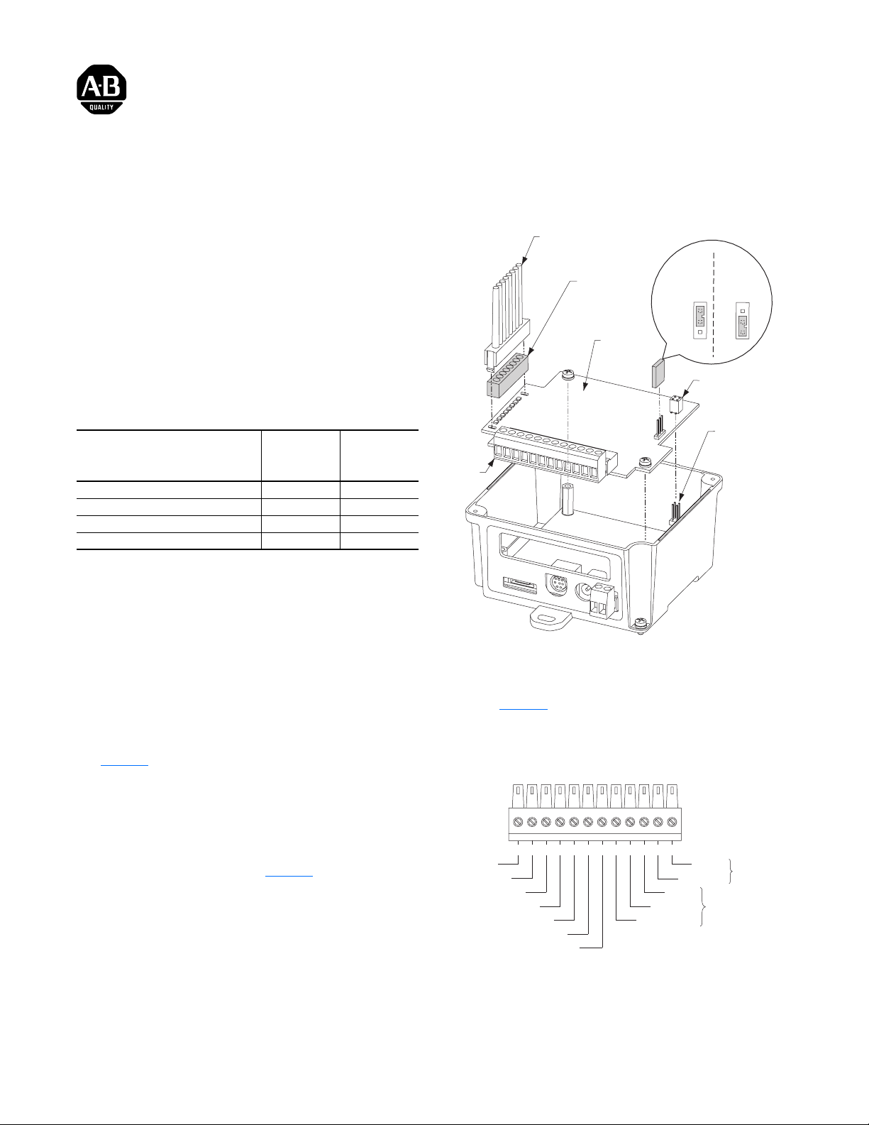
Figure 1 Installing the Optional I/O Board
Light Pipe
Black Bezel
I/O Board
J1
JMP1 Fault Action Jumper
FLT (Fault)
Configurable
Position
JMP1 FLT JMP1 FLT
HLS (Hold
Last State)
Position
1
1
2
2
3
3
HLS
I/O Board Socket
Power Supply
Board
Mating Plug
HLS
Installing the I/O Board
1. Remove J1, 12-position Terminal Block Connector.
2. Insert the black bezel into the base of the light pipe
(Figure 1
3. Carefully align the light pipe assembly over the 8 LED
indicators and snap it into the slots on the board.
4. Set JMP 1 Fault Action Jumper for either Fault
Configurable (FLT position, pins 1-2) or Hold Last State
(HLS position, pins 2-3). See Figure 1
5. Carefully align the I/O board socket onto the mating plug
of the Comm Kit’s power supply board while placing the
I/O board onto the three standoffs.
6. Fasten the I/O board to the standoffs using the three
screws supplied with the I/O board.
7. Reinstall J1, 12-position Terminal Block Connector.
8. Fasten the enclosure cover onto the Comm Kit’s base
using the two screws in the cover.
).
for details.
I/O Wiring
Refer to Figure 2 for I/O function descriptions for each
terminal point on the I/O connector.
Figure 2 I/O Connector Function Descriptions
IN3
IN4
INPUT COM
345 621 9 10 11 1287
IN5
IN6
O1 - COM
O1 - NO
O2 - COM
O1 - NC
O2 - NO
OUT1
OUT2
IN1
IN2
Page 2
A
A
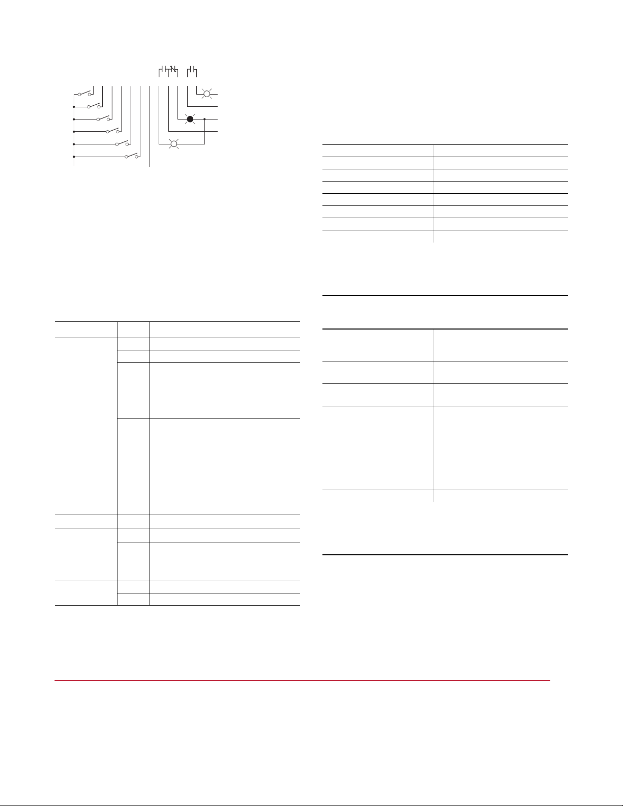
Figure 3 I/O Wiring Example
1
2 3 4 5 6 7 8 9 10 11 12
24 VDC
(+)
0 VDC
(-)
Power Source (AC or DC)
Power Neutral / Common
Power Source (AC or DC)
Power Neutral / Common
(1)
Output commons are isolated.
(1)
(1)
Configuring the 20-COMM-* Adapter for I/O
When the optional I/O board is installed and the Comms Kit
is mounted and connected, configure the I/O inputs and
outputs. Refer to the communication adapter User Manual
for complete details.
I/O Board LED Indicators
LED Name State Description
IN1 (Input 1) Green Normal operation, Input 1 ON
Off Normal operation, Input 1 OFF
Solid
Red
Flashing
Red
Orange OPT1 self-diagnostics failure
IN2 (Input 2)
IN3 (Input 3)
IN4 (Input 4)
IN5 (Input 5)
IN6 (Input 6)
OUT1 (Output 1)
OUT2 (Output 2)
Green
Off
Green Output * ON
Off Output * OFF
Communication with the 20-COMM-*
adapter has not been established.
Possible Reasons: Wrong adapter/series/
firmware (see table above), or bad
connection.
Fault - 20-COMM-* adapter has
experienced an Idle or Comm fault, and the
I/O board is taking its configured fault action
for the outputs.
Possible Reasons: Controller in Stop mode
or powered down, DPI connector
disconnected from drive or drive powered
down, or network connector disconnected
from 20-COMM-* adapter.
Input * ON
Input * OFF
(1)
(1)
(1)
These LEDs will indicate input status when the IN1 LED is in normal operation
(Green or Off) and communicating with the Comm adapter. If the IN1 LED
indicates a problem (Solid Red, Flashing Red or Orange), these LEDs will be
turned Off and will not indicate input status.
I/O Board Specifications
Inputs
Number of Inputs 6 (single common)
Input Voltage Type 24 VDC source load
Maximum Input Voltage 27 VDC
Maximum Input Current 8 mA (each input)
Guaranteed ON-State Voltage 10 - 27 VDC (3 mA minimum)
Guaranteed OFF-State Voltage 0 - 5 VDC (2 mA maximum)
Reverse Polarity Protected -30 VDC
Response Time 25 ms + network update time
The I/O board is NOT designed for fast I/O response times. Do NOT use
with input devices that will transition (OFF J ON J OFF) faster than the
response time. Potential input devices include auxiliary contact inputs
from relays or overloads, pushbuttons, etc.
Outputs
Number of Outputs 2 relay outputs (individually isolated)
1 - Form C contacts
1 - Form A (NO) contact
Maximum Output
Contact Voltage
Maximum Output
Contact Current
Expected Contact Life 1,000,000 cycles resistive at < 0.5A
Response Time 25 ms + network update time
The I/O board is NOT designed for fast I/O response times. Do NOT use
with output devices that need to transition (OFF J ON J OFF) faster
than the response time. Potential output devices include pilot lights or a
contact closure reset to another hardware device.
27 VDC / 125 VAC
2A
500,000 cycles inductive at < 0.5A
500,000 cycles resistive at 1A
300,000 cycles inductive at 1A
300,000 cycles resistive at 2A
150,000 cycles inductive at 2A
U.S. Allen-Bradley Drives Technical Support - Tel: (1) 262.512.8176, Fax: (1) 262.512.2222, Email: support@drives.ra.rockwell.com, Online: www.ab.com/support/abdrives
www.rockwellautomation.com
Power, Control and Information Solutions Headquarters
mericas: Rockwell Automation, 1201 South Second Street, Milwaukee, WI 53204-2496 USA, Tel: (1) 414.382.2000, Fax: (1) 414.382.4444
Europe/Middle East/Africa: Rockwell Automation, Vorstlaan/Boulevard du Souverain 36, 1170 Brussels, Belgium, Tel: (32) 2 663 0600, Fax: (32) 2 663 0640
sia Pacific: Rockwell Automation, Level 14, Core F, Cyberport 3, 100 Cyberport Road, Hong Kong, Tel: (852) 2887 4788, Fax: (852) 2508 1846
Publication 20COMM-IN002C-EN-P – May 2007 P/N 328356-P03
Supersedes 20COMM-IN002B-EN-P – July 2006 Copyright © 2007 Rockwell Automation, Inc. All rights reserved. Printed in USA.
 Loading...