

Page 1

RS-485 DF1
Adapter
20-COMM-S
FRN 1.xxx
User Manual
Page 2

Important User Information
Solid state equipment has operational characteristics differing from those of
electromechanical equipment. “
and Maintenance of Solid State Controls
important differences between solid state equipment and hard-wired
electromechanical devices. Because of this difference, and also because of the
wide variety of uses for solid state equipment, all persons responsible for applying
this equipment must satisfy themselves that each intended application of this
equipment is acceptable.
In no event will the Allen-Bradley Company be responsible or liable for indirect or
consequential damages resulting from the use or application of this equipment.
The examples and diagrams in this manual are included solely for illustrative
purposes. Because of the many variables and requirements associated with any
particular installation, the Allen-Bradley Company cannot assume responsibility or
liability for actual use based on the examples and diagrams.
No patent liability is assumed by Allen-Bradley Company with respect to use of
information, circuits, equipment, or software described in this manual.
Reproduction of the contents of this manual, in whole or in part, without written
permission of the Allen-Bradley Company is prohibited.
Throughout this manual we use notes to make you aware of safety considerations.
Safety Guidelines for the Application, Installation
” (Publication SGI-1.1) describes some
ATTENTION:
that can lead to personal injury or death, property damage, or economic
!
loss.
Attentions help you:
•
identify a hazard
•
avoid the hazard
•
recognize the consequences
Important:
Identifies information that is especially important for successful
application and understanding of the product.
Shock Hazard
people that dangerous voltage may be present.
Identifies information about practices or circumstances
labels may be located on or inside the drive to alert
Page 3

Summary of Changes
This is the first release of the RS-485 DF1 FRN 1.xxx.
Page 4

2
Notes:
Page 5

Preface About This Manual
Related Documentation . . . . . . . . . . . . . . . . . . . . . . . . . . . . . P-1
Conventions Used in this Manual . . . . . . . . . . . . . . . . . . . . . P-2
Rockwell Automation Support. . . . . . . . . . . . . . . . . . . . . . . . P-2
Chapter 1 Getting Started
Components . . . . . . . . . . . . . . . . . . . . . . . . . . . . . . . . . . . . . . 1-1
Features . . . . . . . . . . . . . . . . . . . . . . . . . . . . . . . . . . . . . . . . . 1-2
Compatible Products . . . . . . . . . . . . . . . . . . . . . . . . . . . . . . . 1-3
Required Equipment . . . . . . . . . . . . . . . . . . . . . . . . . . . . . . . 1-3
Safety Precautions . . . . . . . . . . . . . . . . . . . . . . . . . . . . . . . . . 1-4
Quick Start . . . . . . . . . . . . . . . . . . . . . . . . . . . . . . . . . . . . . . . 1-5
Modes of Operation . . . . . . . . . . . . . . . . . . . . . . . . . . . . . . . . 1-6
Chapter 2 Installing the Adapter
Preparing for an Installation. . . . . . . . . . . . . . . . . . . . . . . . . . 2-1
Commissioning the Adapter. . . . . . . . . . . . . . . . . . . . . . . . . . 2-1
Connecting the Adapter to the Network. . . . . . . . . . . . . . . . . 2-3
Connecting the Adapter to the Drive . . . . . . . . . . . . . . . . . . . 2-4
Applying Power . . . . . . . . . . . . . . . . . . . . . . . . . . . . . . . . . . . 2-6
Chapter 3 Configuring the Adapter
Configuration Tools . . . . . . . . . . . . . . . . . . . . . . . . . . . . . . . . 3-1
Using DriveExplorer . . . . . . . . . . . . . . . . . . . . . . . . . . . . . . . 3-2
Using the PowerFlex HIM . . . . . . . . . . . . . . . . . . . . . . . . . . . 3-3
Setting the Node Address. . . . . . . . . . . . . . . . . . . . . . . . . . . . 3-4
Setting the Data Rate . . . . . . . . . . . . . . . . . . . . . . . . . . . . . . . 3-4
Setting the CRC/BCC Selection . . . . . . . . . . . . . . . . . . . . . . 3-5
Setting a Fault Action. . . . . . . . . . . . . . . . . . . . . . . . . . . . . . . 3-5
Resetting the Adapter. . . . . . . . . . . . . . . . . . . . . . . . . . . . . . . 3-7
Viewing the Adapter Configuration . . . . . . . . . . . . . . . . . . . . 3-8
Table of Contents
Chapter 4 Using DriveExplorer on the RS-485 Network
Drive Explorer . . . . . . . . . . . . . . . . . . . . . . . . . . . . . . . . . . . . 4-1
Chapter 5 Troubleshooting
Locating the Status Indicators . . . . . . . . . . . . . . . . . . . . . . . . 5-1
PORT Status Indicator . . . . . . . . . . . . . . . . . . . . . . . . . . . . . . 5-2
MOD Status Indicator . . . . . . . . . . . . . . . . . . . . . . . . . . . . . . 5-3
Net A Status Indicator . . . . . . . . . . . . . . . . . . . . . . . . . . . . . . 5-3
Net B Status Indicator . . . . . . . . . . . . . . . . . . . . . . . . . . . . . . 5-4
Module Diagnostic Items . . . . . . . . . . . . . . . . . . . . . . . . . . . . 5-5
Module Diagnostic Items (continued) . . . . . . . . . . . . . . . . . . 5-6
Viewing and Clearing Events. . . . . . . . . . . . . . . . . . . . . . . . . 5-7
Page 6

ii
Table of Contents
Appendix A Specifications
Communications . . . . . . . . . . . . . . . . . . . . . . . . . . . . . . . . . . A-1
Electrical . . . . . . . . . . . . . . . . . . . . . . . . . . . . . . . . . . . . . . . . A-1
Mechanical . . . . . . . . . . . . . . . . . . . . . . . . . . . . . . . . . . . . . . . A-1
Environmental . . . . . . . . . . . . . . . . . . . . . . . . . . . . . . . . . . . . A-2
Regulatory Compliance . . . . . . . . . . . . . . . . . . . . . . . . . . . . . A-2
Appendix B Adapter Parameters
About Parameter Numbers. . . . . . . . . . . . . . . . . . . . . . . . . . . B-1
Parameter List . . . . . . . . . . . . . . . . . . . . . . . . . . . . . . . . . . . . B-1
Appendix C Logic Command/Status Words
PowerFlex 70 and PowerFlex 700 Drives . . . . . . . . . . . . . . . C-1
Glossary
Index
Page 7

Preface
About This Manual
Topic Page
Related Documentation
Conventions Used in this Manual P-2
Rockwell Automation Support P-2
Related Documentation
For: Refer to: Publication
DF1 Protocol
DriveExplorer™
DriveTools 2000™
PowerFlex™ HIM
PowerFlex™ 70 Drive
PowerFlex™ 700 Drive
RSLinx™
DF1 Protocol and Command Set Reference manual
DriveExplorer Getting Results Manual
Online help (installed with the software)
http://www.ab.com/drives/drivetools_2000
Online help (installed with the software)
HIM Quick Reference
PowerFlex 70 User Manual
PowerFlex 70 Reference Manual
PowerFlex 700 User Manual
PowerFlex 700 Reference Manual
Getting Results with RSLinx
Online help (installed with the software)
P-1
1770-6.5.16
9306-GR001…
20HIM-QR001…
20A-UM001…
20A-RM001…
20B-UM001…
20B-RM001…
9399-WAB32GR
Documentation can be obtained online at http://www.ab.com/manuals
Page 8

P-2
About This Manual
Conventions Used in this Manual
The following conventions are used throughout this manual:
•
Parameter names are shown in the following format
- [*]
. The xxx represents the parameter number. The * represents the
parameter name. For example
•
Menu commands are shown in bold type face and follow the format
Menu > Command
you should click the
•
The firmware release is displayed as FRN X.xxx. The “FRN”
. For example, if you read “Select
File
Parameter 01 - [DPI Port]
menu and then click the
Parameter xxx
.
File > Open
Open
command.
signifies Firmware Release Number. The “X” is the major release
number. The “xxx” is the minor update number.
Rockwell Automation Support
Rockwell Automation offers support services worldwide, with over 75
sales/support offices, over 500 authorized distributors, and over 250
authorized systems integrators located through the United States alone.
In addition, Rockwell Automation representatives are in every major
country in the world.
,”
Local Product Support
Contact your local Rockwell Automation representative for sales and
order support, product technical training, warranty support, and support
service agreements.
Technical Product Assistance
If you need to contact Rockwell Automation for technical assistance,
please review the information in Chapter 5
still have problems, then call your local Rockwell Automation
representative
U.S. Allen-Bradley Drives Technical Support
E-mail: support@drives.ra.rockwell.com
Tel: (1) 262.512.8176
Fax: (1) 262.512.2222
http://www.ab.com/support/abdrives
Online:
, Troubleshooting first. If you
:
Page 9
Chapter
1
Getting Started
The RS-485 DF1 (20-COMM-S) is an embedded communication option
for any one drive in the PowerFlex 7-Class family. It can also be used
with other Allen-Bradley products implementing DPI™, a functional
enhancement to SCANport™.
Topic Page Topic Page
Components
Features 1-2 Quick Start 1-5
Compatible Products 1-3 Modes of Operation 1-6
Required Equipment 1-3
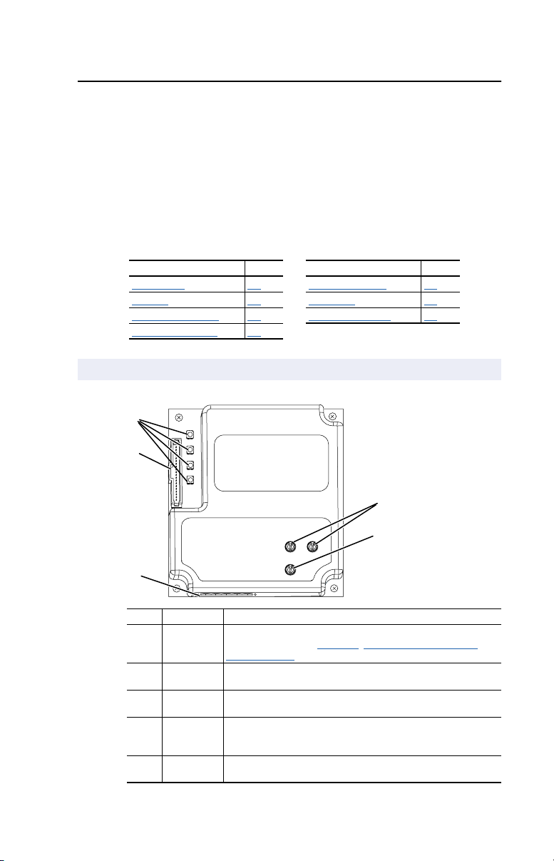
Components
Figure 1.1 Components of the Adapter
➊
➋
1-1 Safety Precautions 1-4
➌
# Part Description
➊
➋
➌
➍
➎
Status
Indicators
DPI
Connector
RS-485 DF1
Connector
Node
Address
Switches
Data Rate
Switch
Four LEDs that indicate the status of the connected drive, adapter,
and network. Refer to Chapter 4
RS-485 Network.
A 20-pin, single-row shrouded male header. An Internal Interface
cable is connected to this connector and a connector on the drive.
A 6-pin connector to which a 6-pin linear plug can be connected.
Switches for setting the node address.
Switch for setting the RS-485 DF1 data rate at which the adapter
communicates.
➍
➎
, Using DriveExplorer on the
Page 10

1-2
Getting Started
Features
The RS-485 DF1 adapter features the following:
•
The adapter is mounted in and receives power from the PowerFlex
drive. Captive screws are used to secure and ground the adapter to
the drive.
•
Switches let you set a node address and network data rate before
applying power to the PowerFlex drive. Alternatively, you can
disable the switches and use parameters to configure these features.
•
A number of configuration tools can be used to configure the adapter
and connected drive. The tools include the PowerFlex HIM on the
drive, or drive-configuration software such as DriveExplorer (version
2.02 or higher) or DriveTools 2000 (version 1.01 or higher).
•
Status indicators report the status of the drive communications,
adapter, and network. They are visible both when the cover is opened
and when it is closed.
•
Allows DriveExplorer (version 2.02 or higher) to connect to a
PowerFlex drive with a 1203-SSS, and “route” out over RS-485 to
other PowerFlex drives.
•
Allows an RS-485 DF1 Master device to access the PowerFlex drive:
–
Logic Command/Reference
–
Logic Status Feedback
–
Datalinks A-D
–
Explicit message support
•
User defined fault actions determine how the adapter and PowerFlex
drive respond to communication disruptions on the network.
Page 11

Getting Started
Compatible Products
DPI is a second generation peripheral communication interface (see
Glossary). The RS-485 DF1 adapter is compatible with Allen-Bradley
PowerFlex drives and other products that support DPI. DPI is a
functional enhancement to SCANport. At the time of publication,
compatible products include:
•
PowerFlex 70 drives
•
PowerFlex 700 drives
•
PowerFlex 7000 drives
Required Equipment
Equipment Shipped with the Adapter
When you unpack the adapter, verify that the package includes:
❑
One RS-485 DF1 adapter
❑
A 2.54 cm (1 in.) and a 15.24 cm (6 in.) Internal Interface cable
(only one cable is needed to connect the adapter to the drive)
❑
One six-pin linear RS-485 DF1 plug
(connected to the RS-485 DF1 connector on the adapter)
❑
One grounding wrist strap
❑
This manual
1-3
User-Supplied Equipment
To install and configure the RS-485 DF1 adapter, you must supply:
❑
A small flathead or Phillips screwdriver
❑
RS-485 cable (Belden 3106A or equivalent recommended)
❑
Configuration tool, such as:
– PowerFlex HIM
– DriveExplorer (version 2.02 or higher) or DriveTools 2000
(version 1.01 or higher)
- 1203-SSS AnaCANda (version 3.001 or higher)
Page 12

1-4
Getting Started
Safety Precautions
Please read the following safety precautions carefully
.
ATTENTION:
personnel familiar with drive and power products and the associated
!
machinery should plan or implement the installation, start-up,
configuration, and subsequent maintenance of the product using a
RS-485 DF1 adapter. Failure to comply may result in injury and/or
equipment damage.
ATTENTION:
may contain high voltages that can cause injury or death. Remove all
!
power from the PowerFlex drive, and then verify power has been
removed before installing or removing a RS-485 DF1 adapter.
ATTENTION:
SCANport host products must not be directly connected together via
!
1202-C* cables. Unpredictable behavior due to timing and other
internal procedures can result if two or more devices are connected in
this manner.
ATTENTION:
RS-485 DF1 adapter is transmitting control I/O to the drive, the drive
!
may fault when you reset the adapter. Determine how your drive will
respond before resetting an adapter.
ATTENTION:
Parameter 10 - [Comm Flt Action]
!
the adapter and connected PowerFlex drive if communications are
disrupted. By default, this parameter faults the PowerFlex drive. You
can set this parameter so that the PowerFlex drive continues to run.
Precautions should be taken to ensure that the setting of this parameter
does not create a risk of injury or equipment damage.
Risk of injury or equipment damage exists. Only
Risk of injury or death exists. The PowerFlex drive
Risk of injury or equipment damage exists. DPI or
Risk of injury or equipment damage exists. If the
Risk of injury or equipment damage exists.
lets you determine the action of
ATTENTION:
system is configured for the first time, there may be unintended or
!
incorrect machine motion. Disconnect the motor from the machine or
process during initial system testing.
Risk of injury or equipment damage exists. When a
Page 13

Getting Started
1-5
Quick Start
This section is designed to help experienced users configure or set up the
RS-485 DF1 adapter. If you are unsure how to complete a step, refer to
the referenced chapter.
Step
1 Review the safety precautions for the adapter.
2 Verify that the PowerFlex drive is properly installed.
3 Commission the adapter.
Set a unique node address and the appropriate data rate using
the switches on the adapter. If desired, you can disable the
switches and use parameter settings instead.
4 Install the adapter.
Verify that the PowerFlex drive is not powered. Then, connect the
adapter to the network using a RS-485 cable and to the drive
using the Internal Interface cable. Use the captive screws to
secure and ground the adapter to the drive.
5 Apply power to the adapter.
The adapter receives power from the drive and network. Apply
power to the network and to the drive. The status indicators
should be green. If there is a problem, refer to Chapter
DriveExplorer on the RS-485 Network.
6 Configure the adapter for your application.
Set the parameters for the following features as required by your
application:
•
I/O configuration.
•
Fault actions.
7 Apply power to the RS-485 DF1 master.
Verify that the master and network are installed and functioning in
accordance with RS-485 DF1 standards.
4, Using
Refer to
Throughout This
Manual
Drive User
Manual
Chapter 2,
Installing the
Adapter
Chapter
2,
Installing the
Adapter
Chapter 2,
Installing the
Adapter
Chapter
3,
Configuring the
Adapter
Page 14
1-6
PWR
STS
PORT
MOD
NET A
NET B
Getting Started
Modes of Operation
The adapter uses four status indicators to report its operating status. They
can be viewed on the adapter or through the drive cover. See Figure 1.2
.
Figure 1.2 Status Indicators
(location on drive may vary)
➊
➋
➌
➍
➊
➋
➌
➍
# Status
Indicator
➊
PORT Green Normal Operation. The adapter is properly connected and
➋ MOD Green Normal Operation. The adapter is operational and is
➌ NET A Green Normal Operation. The adapter is properly connected and
➍ NET B Flashing
(1)
If all status indicators are off, the adapter is not receiving power. Refer to Chapter 2,
Installing the Adapter, for instructions on installing the adapter. If any other conditions
occur, refer to Chapter 4, Using DriveExplorer on the RS-485 Network.
Status
Flashing
Green
Flashing
Green
Flashing
Green
Green
(1)
Description
is communicating with the drive.
The adapter is in the process of establishing a connection
to the drive. This status indicator will turn solid green or
red.
transferring I/O data.
Normal Operation. The adapter is operational, but is not
transferring I/O data.
communicating on the network.
The adapter is properly connected, but is not
communicating with any devices on the network.
Module receiving data.
Page 15

Chapter 2
Installing the Adapter
Chapter 2 provides instructions for installing the adapter on a PowerFlex
drive.
Topic Page
ing for an Installation 2-1
Prepar
Commissioning the Adapter 2-1
Connecting the Adapter to the Network 2-3
Connecting the Adapter to the Drive 2-4
Applying Power 2-6
Preparing for an Installation
Before installing the RS-485 DF1 adapter:
• Verify that you have all required equipment. Refer to Chapter 1
Getting Started
.
Commissioning the Adapter
To commission the adapter, you must set a unique node address, the data
rate used by the network and the error checking method. (Refer to the
Glossary for details).
Important: New settings are recognized only when power is applied to
the adapter or the adapter is reset. If you change a setting,
cycle power or perform a reset.
ATTENTION: Risk of equipment damage exists. The RS-485 DF1
adapter contains ESD (Electrostatic Discharge) sensitive parts that can
!
be damaged if you do not follow ESD control procedures. Static control
precautions are required when handling the adapter. If you are
unfamiliar with static control procedures, refer to Guarding Against
Electrostatic Damage, Publication 8000-4.5.2.
,
Page 16
2-2 Installing the Adapter
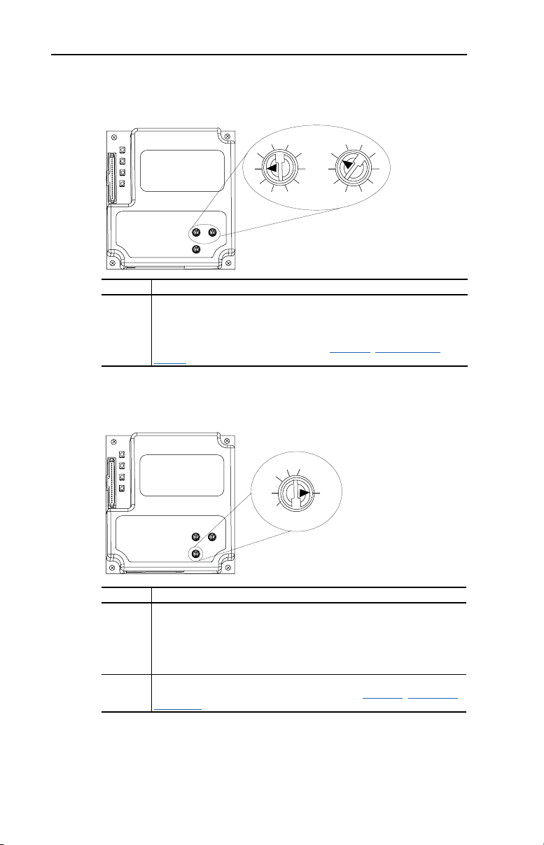
1. Set the node address switches.
Figure 2.1 Setting the Node Address
1
0
9
Tens
Digit
2
3
7
8
2
3
4
1
0
5
9
6
4
5
6
7
8
Ones
Digit
Setting Description
0 – 99 Node address used by the adapter if switches are enabled. The default
switch setting is 1.
Important: If the Data Rate switch is set to “PGM” (Program), the adapter
will use the setting of Parameter 03 - [DF1 Addr Cfg] for the node address.
The default parameter setting is 1. Refer to Chapter
3, Configuring the
Adapter.
2. Set the Data Rate switch.
Figure 2.2 Setting the Data Rate
19.2K
9600
4800
2400
1200
38.4K
PGM
Setting Description
1200
The adapter is set to the respective data rate.
2400
4800
9600
19.2K
38.4K
PGM The adapter uses the setting of Parameter 05 - [DF1 Rate Cfg] for the data
rate. 9600 is the default parameter setting. Refer to Chapter 3, Configuring
the Adapter.
Page 17
Installing the Adapter 2-3
Connecting the Adapter to the Network
ATTENTION: Risk of injury or death exists. The PowerFlex drive
may contain high voltages that can cause injury or death. Remove
!
power from the drive, and then verify power has been discharged before
installing or removing an adapter.
1. Remove power from the drive.
2. Use static control precautions.
3. Connect an RS-485 cable to the network, and route it through the
bottom of the PowerFlex drive.
4. Connect a 6-pin linear plug to the RS-485 cable.
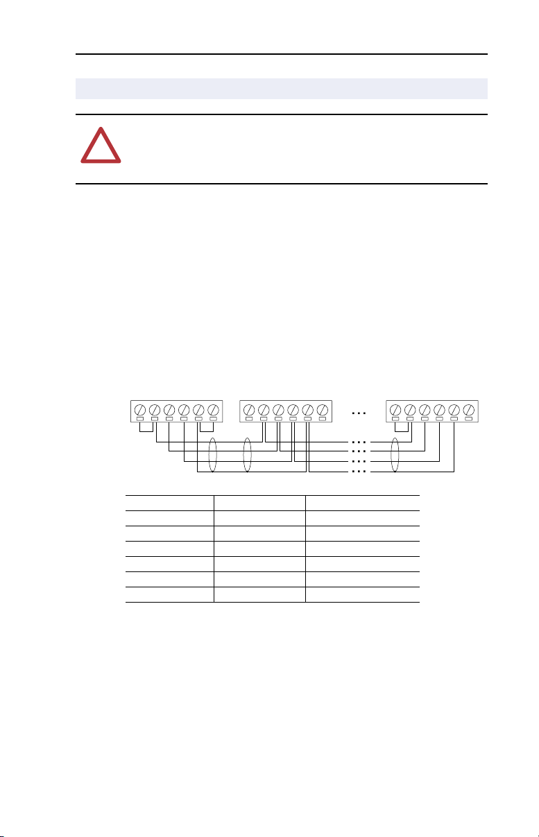
Figure 2.3 Example Network Connections
Node 1 Node 2 Node "n"
TERMAB
Terminal Signal Function
GND CHASSIS GND
COM
SHIELD
GND
TERMAB
COM
SHIELD
GND
(1)
Shield GND termination
TERMAB
COM
SHIELD
GND
SHIELD SHIELD Shield RC termination
COM COMMON Signal Common
B Signal B Tx Rx D-
A Signal A Tx Rx D+
TERM TERMINATION
(2)
Signal RC termination
(1) The shield must be grounded at a single point on the network (jumper terminals
SHIELD and GND).
(2) Jumper Terminals TERM and A on the adapters at end of the RS-485 network. This
enables a built in RC termination network on the adapter.
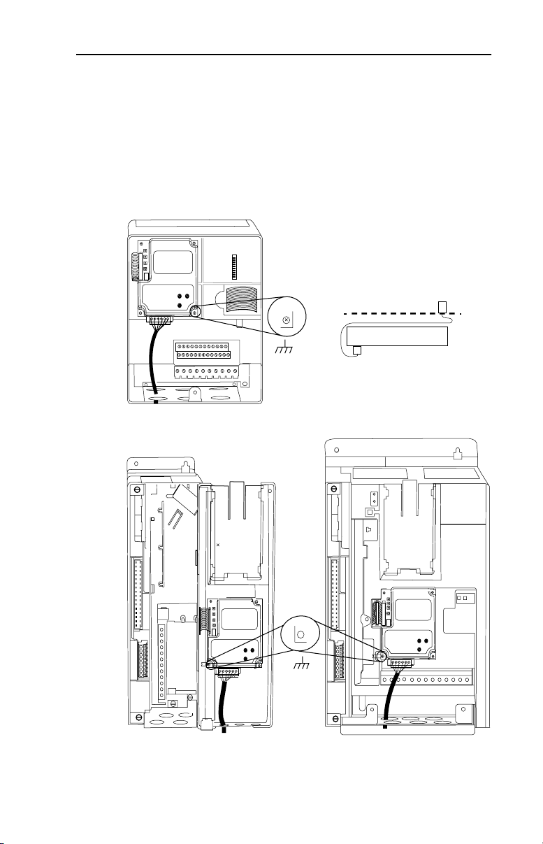
5. Connect the cable to the adapter.
Page 18
2-4 Installing the Adapter
Connecting the Adapter to the Drive
1. Remove power from the drive.
2. Use static control precautions.
3. Connect the Internal Interface cable to the DPI port on the drive and
then to DPI connector on the adapter.
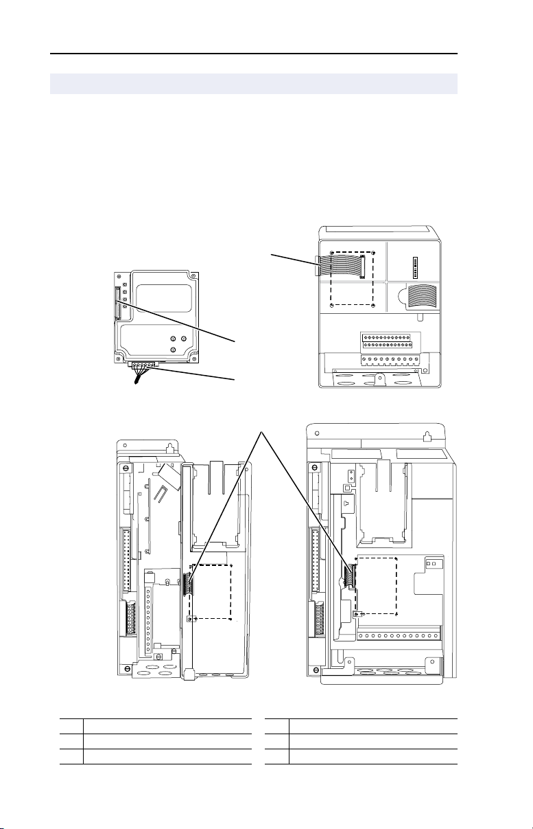
Figure 2.4 DPI Ports and Internal Interface Cables
➊
➋
RS-485 DF1 Adapter
➌
PowerFlex 70 Drive
➍
PowerFlex 700 Drive
0 - 1 Frame
# Description # Description
➊ 15.24 cm (6 in.) Internal Interface cable ➌ RS-485 connector
➋ DPI connector ➍ 2.54 cm (1 in.) Internal Interface cable
PowerFlex 700 Drive
2 Frame & Larger
Page 19
Installing the Adapter 2-5
4. On a PowerFlex 70, fold the Internal Interface cable behind the
adapter and mount the adapter on the drive using the four captive
screws. On a PowerFlex 700, just mount the adapter on the drive
using the four captive screws to secure and ground it to the drive.
Important: All screws must be tightened since the adapter is grounded
through a screw. Recommended torque is 0.9 N-m (8.0
lb.-in.)
Figure 2.5 Mounting the Adapter
Drive
Adapter
Internal Interface cable folded
behind the adapter and in front of drive.
PowerFlex 70 Drive
Adapter mounts in drive.
PowerFlex 700 Drive (0 - 1 Frames)
Adapter mounts on door.
PowerFlex 700 Drive (2 Frame & Larger)
Adapter mounts in drive.
Page 20

2-6 Installing the Adapter
Applying Power
ATTENTION: Risk of equipment damage, injury, or death exists.
Unpredictable operation may occur if you fail to verify that parameter
!
settings and switch settings are compatible with your application.
Verify that settings are compatible with your application before
applying power to the drive.
1. Close the door or reinstall the cover on the drive. The status
indicators can be viewed on the front of the drive after power has
been applied.
2. Ensure that the adapter will have a unique address on the network
and is set at the correct data rate. If a new data rate or address is
needed, reset its switches (Refer to Commissioning the
this chapter.)
3. Apply power to the PowerFlex drive. The adapter receives its power
from the connected drive. When you apply power to the product for
the first time, the status indicators should be green after an
initialization. If there is a problem, refer to Chapter
DriveExplorer on the RS-485 Network.
Adapter in
4, Using
4. If the data rate switch is set to “PGM,” use a configuration tool to set
the data rate and node address parameters in the adapter (Chapter
Confi
guring the Adapter).
5. Verify that the master and network are installed and functioning in
accordance with RS-485 DF1 standards.
3,
Page 21

Chapter 3
Configuring the Adapter
Chapter 3 provides instructions and information for setting the
parameters in the adapter.
Topic Page Topic Page
guration Tools 3-1 Setting a Fault Action 3-5
Confi
Using the PowerFlex HIM 3-3 Resetting the Adapter 3-7
Setting the Node Address 3-4 Viewing the Adapter Configuration 3-8
Setting the Data Rate 3-4
For a list of parameters, refer to Appendix
definitions of terms in this chapter, refer to the Glossary
B, Adapter Parameters. For
.
Configuration Tools
The RS-485 DF1 adapter stores parameters and other information in its
own non-volatile memory. You must, therefore, access the adapter to
view and edit its parameters. The following tools can be used to access
the adapter parameters:
Tool Refer To:
DriveExplorer Software (version 2.02
or higher)
DriveExecutive Software (version 1.01
or higher)
PowerFlex HIM page 3-3
DriveExplorer Getting Results Manual,
Publication 9306-5.3, or the online help
DriveTools 2000 Online Help
Page 22

3-2 Configuring the Adapter
Using DriveExplorer
With DriveExplorer software, you can edit parameters in both the
1203-SSS serial converter and the connected product. On
PowerFlex 70 and PowerFlex 700 drives (or other DPI products), you
can also edit parameters in any of the attached peripherals, such as the
20-COMM-S. DriveExplorer Lite is shipped with the 1203-SSS serial
converter. It is a free, limited-feature version of DriveExplorer.
DriveExplorer Lite Quick Start
This section is designed to help users start using DriveExplorer Lite. If
you are unsure how to complete a step, refer to the online help (select
Help > Help Topics) or the DriveExplorer Getting Results Manual,
Publication 9306-5.2, which is included on the CD.
Step
1 Select Explore > Configure Communication. Select the communications port
and baud rate that you are using. Select either checksum and accept the default
time for the time-out.
2 Select Explore > Connect > Local. A node eventually appears under Devices.
3 In the left pane, click the + signs to expand the tree. Click the product or serial
converter to display parameters in the right pane. Double-click a parameter to edit
it.
Figure 3.1 DriveExplorer
Page 23

Configuring the Adapter 3-3
OR
Sel
ALT
Device
OR
OR
Using the PowerFlex HIM
If your drive has either an LED or LCD HIM (Human Interface Module),
access parameters in the adapter as shown below. It is recommended that
you read through the steps for your HIM before performing the
sequence. For additional HIM information, refer to your PowerFlex
Drive User Manual or the HIM Quick Reference card.
Using an LED HIM
Step Key(s) Example Screens
1. Press the ALT and then Sel
(Device) to display the Device
Screen.
2. Press the Up Arrow or Down
Arrow to scroll to the
20-COMM-S adapter. Letters
represent files in the drive, and
numbers represent ports. The
adapter is usually connected to
port 5.
3. Press the Enter key to enter your
selection. A parameter database
is constructed, and then the first
parameter is displayed.
4. Edit the parameters using the
same techniques that you use to
edit drive parameters.
Using an LCD HIM
Step Key(s) Example Screens
1. In the main menu, press the Up
Arrow or Down Arrow to scroll to
Device Select.
2. Press Enter to enter your
selection.
3. Press the Up Arrow or Down
Arrow to scroll to the
20-COMM-S adapter.
4. Press Enter to select the
20-COMM-S adapter. The main
menu for the adapter is
displayed.
5. Edit the parameters using the
same techniques that you use to
edit drive parameters.
F-> Stopped Auto
0.00 Hz
Main Menu:
Diagnostics
Parameter
Device Select
Port 5 Device
20-COMM-S
Main Menu:
Diagnostics
Parameter
Device Select
Page 24

3-4 Configuring the Adapter
Setting the Node Address
If the adapter Data Rate switch is set to “PGM,” the value of Parameter
03 - [DF1 Addr Cfg] determines the node address.
1. Set the value of Parameter 03 - [DF1 Addr Cfg] to a unique node
address.
Figure 3.2 RS-485 DF1 Node Address Screen on an LCD HIM
Port 5 Device
20-COMM-S
Parameter #: 3
DF1 Addr Cfg
1
0 <> 99
2. Reset the adapter. Refer to the Resetting the Adapter section in this
chapter.
Setting the Data Rate
If the adapter Data Rate switch is set to “PGM,” the value of Parameter
05 - [DF1 Rate Cfg] determines the RS-485 DF1 data rate. Your
application may require a different setting.
Default = 1
1. Set the value of Parameter 05 - [DF1 Rate Cfg] to the data rate at
which your network is operating.
Figure 3.3 RS-485 DF1 Data Rate Screen on an LCD HIM
Port 5 Device
20-COMM-S
Parameter #: 5
DF1 Rate Cfg
3
9600 bps
Value Baud Rate
0 1200 bps
1 2400 bps
2 4800 bps
3 9600 bps (default)
4 19.2 kbps
5 38.4 kbps
2. Reset the adapter. Refer to the Resetting the Adapter section in this
chapter.
Page 25

Configuring the Adapter 3-5
Setting the CRC/BCC Selection
Two types of error checking methods are used with the DF1 protocol,
Cyclic Redundancy Check (CRC) and (BCC).
1. Set the value of Parameter 24 - [CRC/BCC] to the method used by
the network.
Figure 3.4 RS-485 DF1 CRC/BCC Screen on a LCD HIM
Port 5 Device
20-COMM-S
Parameter #: 24
CRC/BCC Cfg
0
BCC
Value Selection
0 BCC (default)
1 CRC
Setting a Fault Action
By default, when communications are disrupted (for example, a cable is
disconnected) or the scanner is idle, the drive responds by faulting if it is
using I/O from the network. You can configure a different response to
communication disruptions using Parameter 10 - [Comm Flt Action].
ATTENTION: Risk of injury or equipment damage exists.
Parameter 10 - [Comm Flt Action] lets you determine the action of
!
the adapter and connected drive if communications are disrupted. By
default, this parameter faults the drive. You can set the parameter so that
the drive continues to run. Precautions should be taken to ensure that
the setting of this parameter does not create a risk of injury or
equipment damage.
Page 26

3-6 Configuring the Adapter
To change the fault action
• Set the values of Parameters 10 - [Comm Flt Action] to the desired
responses:
Value Action Description
0 Fault (default) The drive is faulted and stopped. (Default)
1 Stop The drive is stopped, but not faulted.
2 Zero Data The drive is sent 0 for output data after a
3 Hold Last The drive continues in its present state after a
4 Send Flt Cfg The drive is sent the data that you set in the fault
Figure 3.5 Fault Action Screens on an LCD HIM
Port 5 Device
20-COMM-S
Parameter #: 10
Comm Flt Action
0
Fault
Changes to this parameter takes effect immediately. A reset is not
required.
communications disruption. This does not
command a stop.
communications disruption.
configuration parameters (Parameters 14 - [Flt Cfg
Logic] through 23 - [Flt Cfg D2 In]).
To set the fault configuration parameters
If you set Parameter 10 - [Comm Flt Action] to the send Flt Cfg,” the
values in the following parameters are sent to the drive after a
communications fault occurs. You must set these parameters to values
required by your application.
Parameter Name Description
14 Flt Cfg Logic A 16-bit value sent to the drive for Logic Command.
15 Flt Cfg Ref A 32-bit value (0 – 4294967295) sent to the drive as a
16 – 23 Flt Cfg x1 In or
Flt Cfg x2 In
Changes to these parameters take effect immediately. A reset is not
required.
Reference or Datalink.
Important: If the drive uses a 16-bit Reference or 16-bit
Datalinks, the most significant word of the value must be
set to zero (0) or a fault will occur.
Page 27

Configuring the Adapter 3-7
Resetting the Adapter
Changes to switch settings on some adapter parameters require that you
reset the adapter before the new settings take effect. You can reset the
adapter by cycling power to the drive or by using the following
parameter:
• Set the Parameter 09 - [Reset Module] to Reset Module:
ATTENTION: Risk of injury or equipment damage exists. If the
adapter is transmitting control I/O to the drive, the drive may fault when
!
you reset the adapter. Determine how your drive will respond before
resetting a connected adapter.
Figure 3.6 Reset Screen on an LCD HIM
Port 5 Device
20-COMM-S
Parameter #: 9
Reset Module
1
Reset Module
When you enter 1 = Reset Module, the adapter will be immediately
reset. When you enter 2 = Set Defaults, the adapter will set all adapter
parameters to their factory-default settings. A reset is still required for
some parameter changes to take effect. The value of this parameter will
be restored to 0 = Ready after the adapter is reset.
Value Description
0 Ready (Default)
1 Reset Module
2 Set Defaults
Page 28

3-8 Configuring the Adapter
Viewing the Adapter Configuration
The following parameters provide information about how the adapter is
configured. You can view these parameters at any time.
Number Name Description
01 DPI Port The port on the drive to which the adapter is connected. Usually, it is
02 DPI Data
Rate
04 DF1 Addr Act The node address used by the adapter. This will be one of the
06 DF1 Rate Act The data rate used by the adapter. This will be one of the following
07 Ref/Fdbk Size The size of the Reference/Feedback (16 bits or 32 bits). It is set in
08 Datalink Size The size of the Datalinks (16 bits or 32 bits). It is set in the drive and
11 Active Cfg Source from which the adapter node address and data rate are
13 DPI I/O Act The I/O used by the adapter. This value is the same as
25 CRC/BCC Act Actual Checksum or CRC selection.
26 Dup Msg
Detect
on Port 5.
The data rate used by DPI in the drive. It is set in the drive, and the
adapter detects it.
following values:
• The address set by the Node Address switches.
• The value of Parameter 03 - [DF1 Addr Cfg] if the switches
have been disabled.
• In order for either of the above to take effect, the adapter has to
be reset or power cycled.
values:
• The data rate set by the Data Rate switch.
• The value of Parameter 05 - [DF1 Rate Cfg] if the switches
have been disabled.
• In order for either of the above to take effect, the adapter has to
be reset or power cycled.
the drive and the adapter automatically uses the correct size.
the adapter automatically uses the correct size.
taken. This will be either switches on the adapter or parameters in
EEPROM. It is determined by the settings of the switches on the
adapter.
Parameter 13 - [DPI I/O Config] unless the parameter was
changed and the adapter was not reset.
Bit
Default
Determines if the adapter ignores messages with duplicate TNS
IDs. Normally set to Enable (default). Set to Disable if using a
ProSoft 3150-DFM module or any device which does not increment
the TNS ID.
01234576
10000xxx
Bit Definitions
0 = Cmd/Ref
1 = Datalink A
2 = Datalink B
3 = Datalink C
4 = Datalink D
5 = Not Used
6 = Not Used
7 = Not Used
Page 29

Chapter 4
Using DriveExplorer on the RS-485
Network
Chapter 4 provides instructions for configuring DriveExplorer (version
2.02 or higher) to access PowerFlex drives on the RS-485 network
(Figure 4.1
Figure 4.1 Example RS-485 DF1 Network
Drive Explorer
).
Select Explore > Connect > Network (Figure 4.2).
Figure 4.2
Select Single to connect to a single node on the network. Select
Multiple to connect to multiple nodes and enter the node range (Figure
4.3). “Offline” or “Online” text will be displayed next to the number to
show if the particular node is present on the network. In this example,
two nodes with DFI addresses of 1 and 2 will be accessed. Click
Connect.
Page 30

4-2 Using DriveExplorer on the RS-485 Network
Figure 4.3
DriveExplorer will perform a search within the range of the selected
nodes and list them (Figure 4.4
Figure 4.4
).
Click on each node to have DriveExplorer perform a device read (Figure
4.5). A “+” will appear to the left of the node upon completion.
Figure 4.5
Page 31

Using DriveExplorer on the RS-485 Network 4-3
Click on the “+” for each node to expand the information (Figure 4.6).
Figure 4.6
Click on the desired item to access its parameters (Figure 4.7).
Figure 4.7
Page 32

4-4 Using DriveExplorer on the RS-485 Network
Notes:
Page 33

Chapter 5
PWR
STS
PORT
MOD
NET A
NET B
Troubleshooting
Chapter 5 contains troubleshooting information.
Topic Page Topic Page
Locating the Status Indicators
PORT Status Indicator 5-2 Module Diagnostic Items 5-5
MOD Status Indicator 5-3 Viewing and Clearing Events 5-7
Locating the Status Indicators
The RS-485 DF1 adapter has four status indicators. They can be viewed
on the adapter or through the drive cover. See Figure 5.1
Figure 5.1 Status Indicators (location on drive may vary)
➊
➋
➌
➍
5-1 Net A Status Indicator 5-3
.
Number Status Indicator Description Page
➊ PORT DPI Connection Status 5-2
➋ MOD Adapter Status 5-3
➌ NET A DF1 Status 5-3
➍ NET B DF1 Traffic 5-4
➊
➋
➌
➍
Page 34

5-2 Troubleshooting
PORT Status Indicator
Status Cause Corrective Action
Off The adapter is not powered or
Flashing
Red
Solid
Red
Orange The adapter is connected to a
Flashing
Green
Solid
Green
is not connected properly to
the drive.
The adapter is not receiving a
ping message from the drive.
The drive has refused an
I/O connection from the
adapter.
Another DPI peripheral is
using the same DPI port as
the adapter.
product that does not support
Allen-Bradley DPI
communications.
The adapter is establishing an
I/O connection to the drive or
Parameter 12 - [DPI I/O
Config] is configured for all
I/O disabled.
The adapter is properly
connected and is
communicating with the drive.
• Securely connect the adapter to the drive
using the ribbon cable.
• Apply power to the drive.
• Verify that cables are securely connected.
• Cycle power to the drive.
Important: Cycle power to the product after
making any of the following corrections.
• Verify that all DPI cables are securely
connected and not damaged. Replace
cables if necessary.
• Verify that the DPI Host supports
Datalinks.
• Configure the adapter to use a Datalink
that is not already being used by another
peripheral.
• Connect the adapter to a product that
supports Allen-Bradley DPI
communications (for example, PowerFlex
drives).
• No Action. This status indicator will turn
solid red.
• Verify Parameter 12 - [DPI I/O Config]
settings.
• Normal behavior if no DPI I/O is enabled.
• No Action.
Page 35

MOD Status Indicator
Status Cause Corrective Action
Off The adapter is not
Flashing
Red
Solid
Red
Flashing
Green
Solid
Green
powered.
The adapter has failed the
firmware test.
The adapter has failed the
hardware test.
The adapter is operational,
but is not transferring I/O
data.
The adapter is operational
and transferring I/O data.
• Securely connect the adapter to the drive
using the ribbon cable.
• Apply power to the drive.
• Clear faults in the adapter.
• Cycle power to the drive.
• If cycling power does not correct the
problem, the parameter settings may
have been corrupted. Reset defaults and
reconfigure the module.
• If resetting defaults does not correct the
problem, flash the adapter with the latest
firmware release.
• Cycle power to the drive.
• Replace the adapter.
• Place the scanner in RUN mode.
• Program the controller to recognize and
transmit I/O to the adapter.
• Configure the adapter for the program in
the controller.
• Normal behavior if no DPI I/O is enabled.
• No action.
Troubleshooting 5-3
Net A Status Indicator
Status Cause Corrective Actions
Off The adapter is not powered
Flashing
Green
Solid
Green
Flashing
Red
or adapter is not connected
properly to the network.
The adapter is properly
connected, but is not
communicating with any
devices on the network.
The adapter is properly
connected and
communicating on the
network.
A network connection has
timed out.
• Securely connect the adapter to the drive
using the Internal Interface cable.
• Correctly connect the RS-485 cable to the
DF1 plug.
• Apply power to the drive.
• Place the controller in RUN mode, or apply
power to the peer device that will send I/O.
• Program a controller or peer device to
recognize and transmit I/O to the adapter.
• Configure the adapter for the program in the
controller or the I/O from the peer device.
• No action required.
• Place the scanner in RUN mode, or apply
power to the peer device that will send I/O.
• Check the amount of traffic on the network.
Page 36

5-4 Troubleshooting
Net B Status Indicator
Status Cause Corrective Actions
Off The adapter is not
Flashing
Green
receiving data over the
network.
The adapter is receiving
data over the network.
• Place the controller in RUN mode, or apply
power to the peer device that will send I/O.
• Program a controller or peer device to
recognize and transmit I/O to the adapter.
• Configure the adapter for the program in the
controller or the I/O from the peer device.
• No action required.
Page 37

Troubleshooting 5-5
Module Diagnostic Items
The following diagnostic items can be accessed using DriveExplorer
(version 2.01 or higher), DriveExecutive (version 1.01 or higher) or
PowerFlex LCD HIM (version 2.001 or higher).
No. Name Description
1 Common Logic
Cmd
2 Prod Logic Cmd Current value of the Product Specific Logic Command being transmitted to
3 Reference Current value of the Product Specific Reference being transmitted to the Host
4 Common Logic
Sts
5 Product Logic
Status
6 Feedback Current value of the Product Specific Feedback being received from the Host
7 Datalink A1 In Current value of Datalink A1 In being transmitted to the Host by this
8 Datalink A2 In Current value of Datalink A2 In being transmitted to the Host by this
9 Datalink B1 In Current value of Datalink B1 In being transmitted to the Host by this
10 Datalink B2 In Current value of Datalink B2 In being transmitted to the Host by this
11 Datalink C1 In Current value of Datalink C1 In being transmitted to the Host by this
12 Datalink C2 In Current value of Datalink C2 In being transmitted to the Host by this
13 Datalink D1 In Current value of Datalink D1 In being transmitted to the Host by this
14 Datalink D2 In Current value of Datalink D2 In being transmitted to the Host by this
15 Datalink A1 Out Current value of Datalink A1 being received from the Host by this peripheral.
16 Datalink A2 Out Current value of Datalink A2 being received from the Host by this peripheral.
17 Datalink B1 Out Current value of Datalink B1 being received from the Host by this peripheral.
18 Datalink B2 Out Current value of Datalink B2 being received from the Host by this peripheral.
19 Datalink C1 Out Current value of Datalink C1 being received from the Host by this peripheral.
20 Datalink C2 Out Current value of Datalink C2 being received from the Host by this peripheral.
21 Datalink D1 Out Current value of Datalink D1 being received from the Host by this peripheral.
Current value of the Common Logic Command being transmitted to the Host
by this peripheral.
the Host by this peripheral.
by this peripheral.
Current value of the Common Logic Status being received from the Host by
this peripheral.
Current value of the Product Specific Logic Status being received from the
Host by this peripheral.
by this peripheral.
peripheral (if not using Datalink A1, this parameter should have a value of
zero).
peripheral (if not using Datalink A2, this parameter should have a value of
zero).
peripheral (if not using Datalink B1, this parameter should have a value of
zero).
peripheral (if not using Datalink B2, this parameter should have a value of
zero).
peripheral (if not using Datalink C1, this parameter should have a value of
zero).
peripheral (if not using Datalink C2, this parameter should have a value of
zero).
peripheral (if not using Datalink D1, this parameter should have a value of
zero).
peripheral (if not using Datalink D2, this parameter should have a value of
zero).
Page 38

5-6 Troubleshooting
Module Diagnostic Items (continued)
22 Datalink D2 Out Current value of Datalink D2 being received from the Host by this peripheral.
23 Field Flash Cnt Current value of the Field Flash Counter.
24 DPI Rx Errors Current value of the DPI CAN Receive Error Counter register.
25 DPI Tx Errors Current value of the DPI CAN Transmit Error Counter Register.
26 Clear DF1
Counts
27 DF1 Packets
Sent
28 DF1 Packets
Rcvd
29 Undelivered
Msgs
30 ENQ’s
Received
31 NAK Bad
Packet
32 NAK No
Memory
33 Duplicate Msgs Reports the number of duplicate messages received the Peripheral. A
34 PCCC I/O
Timeout
35 Data Rate SW The value of the Data Rate SW on the adapter.
36 Node Address SWThe value of the Node Address SW on the adapter.
Ready = No Action
Enable = Clears all DF1 Counter Parameters
Reports the number of DF1 packets sent by the Peripheral.
Reports the number of DF1 packets received by the Peripheral.
Reports the number of DF1 packets that were sent by the Peripheral, but not
acknowledged.
Reports the number of ENQ requests received by the Peripheral.
Reports the number of responses received (BCC or CRC calculated by
Peripheral did not match that in the packet).
Report the number of requests received by the Peripheral that could not be
processed due to insufficient memory available to buffer the incoming packet.
duplicate message is detected when the SRC, TNS and CMD fields of two
consecutive messages are identical.
I/O Communication timeout value (secs) before Pr.10 [Comm Flt Action] is
taken.
Page 39

OR
OR
OR
Troubleshooting 5-7
Viewing and Clearing Events
The adapter maintains an event queue that reports the history of its
actions. You can view the event queue using an LCD PowerFlex HIM,
DriveExplorer (2.01 or higher) software, or DriveExecutive (1.01 or
higher) software.
To view and clear events
Step Keys Example Screen
Viewing Events
1. Access parameters in the adapter.
Refer to Using the PowerFlex HIM in
3.
Chapter
2. Press the Up Arrow or Down Arrow to
scroll to Diagnostics.
3. Press Enter to display the
Diagnostics menu in the adapter.
4. Repeat steps 2 and 3 to enter the
Events option and then View Event
Queue option.
5. Press the Up Arrow or Down Arrow to
scroll through the events. The most
recent event is Event 1.
Clearing Events
1. Access parameters in the Adapter.
Refer to Using the P
Chapter 3.
2. Press the Up Arrow or Down Arrow to
scroll to Diagnostics.
3. Press Enter to display the
Diagnostics menu in the adapter.
4. Repeat steps 2 and 3 to enter the
Events option and then the Clr
Event option or Clear Event Queue
option. A message will pop up to
confirm that you want to clear the
message or queue.
5. Press Enter to clear all events out of
the event queue. All event queue
entries will then display “No Event.”
owerFlex HIM in
Main Menu:
Diagnostics
Parameter
Device Select
Event Q: 1 E3
Ping Time Flt
Dgn: Events
View Event Queue
Clear Event
Clear Event Queue
Page 40

5-8 Troubleshooting
Events
Many events in the Event queue occur under normal operation. If you
encounter unexpected communications problems, the events may help
you or Allen-Bradley personnel may troubleshoot the problem. The
following events may appear in the event queue:
Code Event Description
1 No Event Empty event queue entry.
2 DPI Bus Off Flt A bus-off condition was detected on DPI. This event may be
3 Ping Time Flt A ping message was not received on DPI within the specified
4 Port ID Flt The adapter is not connected to a correct por t on a DPI
5 Port Change
Flt
6 Host Sent
Reset
7 EEPROM Sum
Flt
8 Online @
125 kbps
9 Online @
500 kbps
10 Bad Host Flt The adapter was connected to an incompatible product.
11 Dup. Port Flt Another peripheral with the same port number is already in
12 Type 0 Login The adapter has logged in for type 0 control.
13 Type 0 Time
Flt
14 DL Login The adapter has logged into a Datalink.
15 DL Reject Flt The Host rejected an attempt to log in to a Datalink because
16 DL Time Flt The adapter has not received a Datalink message within the
17 Control
Disabled
18 Control
Enabled
19 PCCC IO Time
Flt
20 Normal
Startup
21 Message
Timeout
caused by loose or broken cables or by noise.
time.
product.
The DPI port changed.
The DPI product issued this because it was reset.
The EEPROM in the adapter is corrupt.
The adapter and DPI product are communicating at 125 kbps.
The adapter and DPI product are communicating at 500 kbps.
use.
The adapter has not received a type 0 status message within
the specified time.
the Datalink is not supported or is used by another peripheral.
specified time.
The adapter has sent a “Soft Control Disable” command to the
DPI product.
The adapter has sent a “Soft Control Enable” command to the
DPI product.
The adapter has not received a PCCC control message within
the specified time-out interval.
The adapter successfully started up.
A Client-Server message sent by the peripheral was not
completed.
Page 41

Troubleshooting 5-9
Events (continued)
Code Event Description
22 DPI Fault Msg The DPI Host has faulted.
23 DPI Fault
Clear
24 Flt Cfg Error At least one of the Fault Configuration parameters contains a
25 DF1 NAK NAK received.
26 Manual Reset The module was reset by the user.
27 Language
CRC Bad
The DPI Host transitions from a faulted to a non-faulted state.
value greater than 65535 and the DPI product expects a 16-bit
value.
The language text memory segment is corrupt.
Page 42

5-10 Troubleshooting
Notes:
Page 43

Appendix A
Specifications
This chapter presents the specifications for the adapter.
Topic Page Topic Page
Comm
unications A-1 Environmental A-2
Electrical A-1 Regulatory Compliance A-2
Mechanical A-1
Communications
Network
Protocol
Data Rates
Drive
Protocol
Data Rates
DF1
1200, 2400, 4800, 9600, 19.2K, 38.4K, PGM
The PGM (Program) setting on the switch is used to set
the data rate using the adapter parameter.
DPI
125K or 500K
Electrical
Consumption
Drive 150 mA at 5 Vdc supplied through the drive
Mechanical
Dimensions
Height
Length
Width
Weight 60g (2 oz.)
16 mm (0.625 inches)
86 mm (3.34 inches)
81 mm (3.16 inches)
Page 44

A-2 Specifications
Environmental
Temperature
Operating
Storage
Relative Humidity -5 to 95% non-condensing
Atmosphere Important: Adapter must not be installed in an area
Regulatory Compliance
UL 508C and CUL
CE EN61800-3
-10 to 50°C (14 to 149°F)
-40 to +85°C (-40 to 185°F)
where the ambient atmosphere contains volatile or
corrosive gas, vapors or dust. If the adapter is not going
to be installed for a period of time, it must be stored in an
area where it will not be exposed to a corrosive
atmosphere.
Page 45

Appendix B
Adapter Parameters
Appendix B provides information about the RS-485 DF1 adapter
parameters.
Topic Page
arameter Numbers B-1
About P
Parameter List B-1
About Parameter Numbers
The parameters in the adapter are numbered consecutively. However,
depending on which configuration tool you use, they may have different
numbers.
Configuration Tool Numbering Scheme
• DriveExplorer
• DriveExecutive
• HIM
The adapter parameters begin with parameter 1. For
example, Parameter 01 - [DPI Port] is parameter 1 as
indicated by this manual.
Parameter List
Parameter
No. Name and Description Details
01 [DPI Port]
Port to which the adapter is connected. This will
usually be port 5.
02 [DPI Data Rate]
Data rate used by the drive. This data rate is set in
the drive, and the adapter detects it.
03 [DF1 Addr Cfg]
Node address if the Data Rate switch is set to
“PGM” (Program).
04 [DF1 Addr Actual]
DF1 node address actually used by the adapter.
Default: 0
Minimum: 0
Maximum: 7
Type: Read Only
Default: 0 = 125 kbps
Values: 0 = 125 kbps
Type: Read Only
Default: 1
Minimum: 0
Maximum: 254
Type: Read/Write
Reset Required: Yes
Default: 1
Minimum: 0
Maximum: 254
Type: Read Only
1 = 500 kbps
Page 46

B-2 Adapter Parameters
Parameter
No. Name and Description Details
05 [DF1 Rate Cfg]
DF1 data rate if the data rate switch is set to
“PGM” (Program).
06 [DF1 Rate Actual]
DF1 data rate actually used by the adapter.
07 [Ref/Fdbk Size]
Size of the Reference/Feedback (determined by
drive).
08 [Datalink Size]
Size of each Datalink word (determined by drive).
09 [Reset Module]
No action if set to “Ready.” Resets the adapter if
set to “Reset Module.” Restores the adapter to its
factory default settings if set to “Set Defaults.” This
parameter is a command. It will be reset to “0 =
Ready” after the command has been performed.
Default: 3 = 9600 bps
Values: 0 = 1200 bps
Type: Read/Write
Reset Required: Yes
Default: 3 = 9600 bps
Values: 0 = 1200 bps
Type: Read Only
Default: 0 = 16-bit
Value: 0 = 16-bit
Type: Read Only
Default: 0 = 16-bit
Values: 0 = 16-bit
Type: Read Only
Default: 0 = Ready
Values 0 = Ready
Type: Read/Write
Reset Required: No
1 = 2400 bps
2 = 4800 bps
3 = 9600 bps
4 = 19.2 kbps
5 = 38.4 kbps
1 = 2400 bps
2 = 4800 bps
3 = 9600 bps
4 = 19.2 kbps
5 = 38.4 kbps
1 = 32-bit
1 = 32-bit
1 = Reset Module
2 = Set Defaults
ATTENTION: Risk of injury or equipment damage exists. If the adapter is
transmitting I/O that controls the drive, the drive may fault when you reset the
adapter. Determine how your drive will respond before resetting a connected
!
adapter.
10 [Comm Flt Action]
Action that the adapter and drive take if the
adapter detects that RS-485 DF1 communications
have been disrupted. This setting is effective only
if I/O that controls the drive is transmitted through
the adapter.
ATTENTION: Risk of injury or equipment damage exists. Parameter 10 - [Comm
Flt Action] lets you determine the action of the adapter and connected drive if
communications are disrupted. By default, this parameter faults the drive. You can
!
set this parameter so that the drive continues to run. Precautions should be taken
to ensure that the setting of this parameter does not create a risk of injury or
equipment damage.
Default: 0 = Fault
Values: 0 = Fault
Type: Read/Write
Reset Required: No
1 = Stop
2 = Zero Data
3 = Hold Last
4 = Send Flt Cfg
Page 47

Parameter
No. Name and Description Details
11 [Active Cfg]
Source from which the adapter node address and
Default: 0 = Switches
Values: 0 = Switches
data rate are taken. This will either be switches on
the adapter or parameters in EEPROM. It is
Type: Read Only
determined by the settings of the switches on the
adapter.
12 [DPI I/O Config]
I/O that is transferred through the adapter.
Default: xxx0 0001
Bit Values: 0 = I/O disabled
Type: Read/Write
Reset Required: Yes
Bit Definitions
Default
Bit
01234576
10000xxx
0 = Cmd/Ref
1 = Datalink A
2 = Datalink B
3 = Datalink C
4 = Datalink D
5 = Not Used
6 = Not Used
7 = Not Used
13 [DPI I/O Active]
I/O that the adapter is actively transmitting. The
value of this parameter will usually be equal to the
value of Parameter 12 - DPI I/O Config.
Bit
Default
Default: xxx0 0001
Bit Values: 0 = I/O disabled
Type: Read Only
Bit Definitions
01234576
0 = Cmd/Ref
10000xxx
1 = Datalink A
2 = Datalink B
3 = Datalink C
4 = Datalink D
5 = Not Used
6 = Not Used
7 = Not Used
14 [Flt Cfg Logic]
Sets the Logic Command data that is sent to the
drive if the following is true:
• Parameter 10 - [Comm Flt Action] is set to
Send Flt Cfg and communications are
Default: 0000 0000 0000 0000
Minimum: 0000 0000 0000 0000
Maximum: 1111 1111 1111 1111
Type: Read/Write
Reset Required: No
disrupted.
The bit definitions will depend on the product to
which the adapter is connected.
15 [Flt Cfg Ref]
Sets the Reference data that is sent to the drive if
the following is true:
• Parameter 10 - [Comm Flt Action] is set to
Send Flt Cfg and communications are
Default: 0
Minimum: 0
Maximum: 4294967295
Type: Read/Write
Reset Required: No
disrupted.
Important: If the drive uses a 16-bit
Reference, the most significant word of this
value must be set to zero (0) or a fault will
occur.
Adapter Parameters B-3
1 = EEPROM
1 = I/O enabled
1 = I/O enabled
Page 48

B-4 Adapter Parameters
Parameter
No. Name and Description Details
16
[Flt Cfg A1]
17
[Flt Cfg A2]
18
[Flt Cfg B1]
19
[Flt Cfg B2]
20
[Flt Cfg C1]
21
[Flt Cfg C2]
22
[Flt Cfg D1]
23
[Flt Cfg D2]
Sets the data that is sent to the Datalink in the
drive if the following is true:
• Parameter 10 - [Comm Flt Action] is set to
Send Flt Cfg and communications are
disrupted.
24
[CRC/BCC Cfg]
Techniques for error detection in data
communications. Must match the technique used
by the software or controller communicating with
the adapter.
25 [CRC/BCC Act]
Actual checksum or CRC selection.
26 [Dup Msg Detect]
Determines if the adapter ignores duplicate
messages. Normally set to Enable (default). Set to
Disable if using a ProSoft 3150-DFM module or
any device which does not increment the TNS ID.
Default: 0
Default: 0
Default: 0
Default: 0
Default: 0
Default: 0
Default: 0
Default: 0
Minimum: 0
Maximum: 4294967295
Type: Read/Write
Reset Required: No
Important: If the drive uses 16-bit
Datalinks, the most significant word of this
value must be set to zero (0) or a fault will
occur.
Default: 0 = BCC
Bit Values: 0 = BCC
Type: Read/Write
Reset Required: Yes
Default: 0 = BCC
Bit Values: 0 = BCC
Type: Read Only
Default: 1 = Enable
Bit Values: 0 = Disable
Type: Read/Write
Reset Required: No
1 = CRC
1 = CRC
1 = Enable
Page 49

Appendix C
Logic Command/Status Words
Appendix C provides the definitions of the Logic Command/Logic
Status words that are used for some products that can be connected to the
RS-485 DF1 adapter. If you do not see the Logic Command/Logic Status
for the product that you are using, refer to your product’s documentation.
PowerFlex 70 and PowerFlex 700 Drives
Logic Command Word
Logic Bits
1514131211109876543210Command Description
x Stop 0 = Not Stop
x Star t* 0 = Not Start
x Jog 0 = Not Jog
x Clear
Faults
x x Direction 00 = No Command
x Local
Control
x MOP
Increment
x x Accel Rate 00 = No Command
x x Decel Rate 00 = No Command
x x x Reference
Select
x MOP
Decrement
* A 0 = Not Stop condition (logic 0) must first be present before a 1 = Start condition will start the drive.
1 = Stop
1 = Start
1 = Jog
0 = Not Clear Faults
1 = Clear Faults
01 = Forward Command
10 = Reverse Command
11 = Hold Direction Control
0 = No Local Control
1 = Local Control
0 = Not Increment
1 = Increment
01 = Accel Rate 1 Command
10 = Accel Rate 2 Command
11 = Hold Accel Rate
01 = Decel Rate 1 Command
10 = Decel Rate 2 Command
11 = Hold Decel Rate
000 = No Command
001 = Ref. 1 (Ref A Select)
010 = Ref. 2 (Ref B Select)
011 = Ref. 3 (Preset 3)
100 = Ref. 4 (Preset 4)
101 = Ref. 5 (Preset 5)
110 = Ref. 6 (Preset 6)
111 = Ref. 7 (Preset 7)
0 = Not Decrement
1 = Decrement
Page 50

C-2 Logic Command/Status Words
PowerFlex 70 and PowerFlex 700 Drives
Logic Status Word
Logic Bits
1514131211109876543210Status Description
x Ready 0 = Not Ready
x Active 0 = Not Active
x Command
Direction
x Actual
Direction
x Accel 0 = Not Accelerating
x Decel 0 = Not Decelerating
x Alar m 0 = No Alarm
x Fault 0 = No Fault
x At Speed 0 = Not At Reference
x x x Local
Control
xxxx Reference 0000 = Ref A Auto
1 = Ready
1 = Active
0 = Reverse
1 = Forward
0 = Reverse
1 = Forward
1 = Accelerating
1 = Decelerating
1 = Alarm
1 = Fault
1 = At Reference
000 = Port 0 (TB)
001 = Port 1
010 = Port 2
011 = Port 3
100 = Port 4
101 = Port 5
110 = Port 6
111 = No Local
0001 = Ref B Auto
0010 = Preset 2 Auto
0011 = Preset 3 Auto
0100 = Preset 4 Auto
0101 = Preset 5 Auto
0110 = Preset 6 Auto
0111 = Preset 7 Auto
1000 = Term Blk Manual
1001 = DPI 1 Manual
1010 = DPI 2 Manual
1011 = DPI 3 Manual
1100 = DPI 4 Manual
1101 = DPI 5 Manual
1110 = DPI 6 Manual
1111 = Jog Ref
Page 51

A Adapter
Devices such as drives, controllers, and computers usually require an
adapter to provide a communication interface between them and a
network such as RS-485 DF1. An adapter reads data on the network and
transmits it to the connected device. It also reads data in the device and
transmits it to the network.
The 20-COMM-S adapter is an adapter that connects, PowerFlex drives
to a RS-485 DF1 network. Adapters are sometimes also called “cards,”
“embedded communication options,” “gateways,” “modules,” and
“peripherals.”
B Block Check Character (BCC)
A technique for error detection in data communications. A character is
added to a transmission block, which is compared with a second BCC
computed by the receiver to determine if the transmission is error free.
C Controller
A controller, also called programmable logic controller, is a solid-state
control system that has a user-programmable memory for storage of
instructions to implement specific functions such as I/O control, logic,
timing, counting, report generation, communication, arithmetic, and data
file manipulation. A controller consists of a central processor, input/
output interface, and memory. See also Scanner.
Glossary
Cyclic Redundancy Check (CRC)
A commonly used technique for error detection in data communications.
A polynomial algorith is performed on the data, and the resultant
checksum is appended at the end of the frame. The receiving device
performs a similar algorithm.
D Data Rate
The data rate is the speed at which data is transferred on the RS-485 DF1
network.
Each device on a RS-485 DF1 network must be set for the same data
rate. You can set the RS-485 DF1 adapter to 1200, 2400, 4800, 9600,
19.2K, or 38.4 kbps.
Page 52

Glossary-2
Datalinks
A Datalink is a type of pointer used by some PowerFlex drives to
transfer data to and from the controller. Datalinks allow specified
parameter value(s) to be accessed or changed without using explicit
messages. When enabled, each Datalink consumes either four bytes or
eight bytes in both the input and output image table of the controller. The
drive determines the size of Datalinks.
DF1
An Allen-Bradley datalink layer protocol that combines features of
subcategories D1 (data transparency) and F1 (2-way simultaneous
transmission with embedded responses) of ANSI x3.28 specification.
DPI
DPI is a second generation peripheral communication interface used by
various Allen-Bradley drives and power products. It is a functional
enhancement to SCANport.
DPI Peripheral
A device that provides an interface between DPI and a network or user.
Peripheral devices are also referred to as “adapters” and “modules.” The
serial converter and PowerFlex HIM are examples of DPI peripherals.
DPI Product
A device that uses the DPI communications interface to communicate
with one or more peripheral devices. For example, a motor drive such as
a PowerFlex drive is a DPI product. In this manual, a DPI product is also
referred to as “product” or “Host.”
DriveExplorer Software
DriveExplorer software is a tool for monitoring and configuring
Allen-Bradley products and adapters. It can be run on computers running
Microsoft Windows 95, Windows 98, Windows NT (version 4.0 or
higher), Windows CE (version 2.0 or higher), Windows ME, Windows
2000, and Windows XP operating systems. DriveExplorer (version 2.02
or higher) can be used to configure this adapter and PowerFlex drives.
Information about DriveExplorer software and a free lite version can be
accessed at http://www.ab.com/drives/driveexplorer.
Page 53

DriveExecutive Software
DriveExecutive is part of the DriveTools2000 software suite designed for
Microsoft Windows 95, Windows 98, Windows NT (4.0 or higher),
Windows ME, Windows 2000, and Windows XP operating systems. This
software suite provides a family of tools that you can use to program,
monitor, control, troubleshoot, and maintain Allen Bradley products.
DriveTools 2000 (version 1.01 or higher) can be used with PowerFlex
drives. Information about DriveTools can be accessed at http://
www.ab.com/drives.
DriveTools
A software suite designed for Microsoft Windows 95, Windows 98, and
Windows NT (4.0 or higher) operating systems. To fully utilize DSI
products, use DriveTools 2000 version 1.01 or higher. This software
suite provides a family of tools that you can use to program, monitor,
control, troubleshoot, and maintain Allen-Bradley products. Information
about DriveTools can be accessed at http://www.ab.com/drives.
F Fault Action
A fault action determines how the adapter and connected product act
when a communications fault (for example, a cable is disconnected)
occurs or when the scanner is switched out of run mode. The former uses
a communications fault action, and the latter uses an idle fault action.
Glossary-3
Fault Configuration
When communications are disrupted (for example, a cable is
disconnected), the adapter and PowerFlex drive can respond with a
user-defined fault configuration. The user sets the data that is sent to the
drive in the fault configuration parameters (Parameters 14 - [Flt Cfg
Logic] through 23 - [Flt Cfg D2]). When a fault action parameter is set
to use the fault configuration and a fault occurs, the data from these
parameters is sent as the Command Logic, Reference, and/or
Datalink(s).
Flash Update
The process of updating firmware in the adapter. The adapter can be
flash updated using the Xmodem protocol and a 1203-SSS Serial
Converter (version 3.001 or higher).
H HIM (Human Interface Module)
A device that can be used to configure and control a PowerFlex drive.
New HIMs (20-HIM-x) can be used to configure connected peripherals.
Page 54

Glossary-4
Hold Last
When communications are disrupted (for example, a cable is
disconnected), the adapter and PowerFlex drive can respond by holding
last. Hold last results in the drive receiving the last data received via the
RS-485 DF1 connection before the disruption. If the drive was running
and using the Reference from the adapter, it will continue to run at the
same Reference.
I I/O Data
I/O data, sometimes called “implicit messages” or “input/output,”
transmit time-critical data such as a Logic Command and Reference. The
terms “input” and “output” are defined from the scanner’s point of view.
Output is transmitted by the scanner and consumed by the adapter. Input
is transmitted by the adapter and consumed by the scanner.
L Logic Command/Logic Status
The Logic Command is used to control the PowerFlex drive (e.g., start,
stop, direction). It consists of one 16-bit word of input to the adapter
from the network. The definitions of the bits in this word depend on the
drive.
The Logic Status is used to monitor the PowerFlex drive (for example,
operating state, motor direction). It consists of one 16-bit word of output
from the adapter to the network. The definitions of the bits in this word
depend on the drive.
N Node Address
A RS-485 DF1 network can have as many as 255 devices connected to it.
Each device on the network must have a unique node address from 0 and
254.
Non-Volatile Storage (NVS)
NVS is the permanent memory of a device. Devices such as the adapter
and drive store parameters and other information in NVS so that they are
not lost when the device loses power. NVS is sometimes called
“EEPROM.”
P Programmable Controller Communications Command (PCCC)
PCCC is the protocol used by some controllers to communicate with
devices on a network. Some software products (i.e., DriveExplorer and
DriveTools 2000), also use PCCC to communicate.
Page 55

Ping
A ping is a message that is sent by a DPI product to its peripheral
devices. They use the ping to gather data about the product, including
whether it can receive messages and whether they can log in for control.
PowerFlex 7-Class Drives
The Allen-Bradley PowerFlex 7-Class family of drives include the
PowerFlex 70 and PowerFlex 700. These drives can be used for
applications ranging from 0.37 kW (0.5 HP) to 3,000 kW (4,000 HP).
All PowerFlex 7-Class drives implement DPI, allowing them to use the
20-COMM-S RS-485 DF1 adapter.
Programmable Controller
A solid-state control system that has a user-programmable memory for
storage of instructions to implement specific functions such as I/O
control, logic, timing, counting, report generation, communication,
arithmetic, and data file manipulation. A controller consists of central
processor, input/output interface, and memory. A controller is designed
as an industrial control system.
R Reference/Feedback
The Reference is used to send a Reference (for example, speed,
frequency, torque) to the product. It consists of one word of input to the
adapter from the network. The size of the word (either a 16-bit word or
32-bit word) is determined by the drive.
Glossary-5
Feedback is used to monitor the speed of a product. It consists of one
word of output from the adapter to the network. The size of the word
(either a 16-bit word or 32-bit word) is determined by the drive.
S Scanner
A scanner is a separate module (of a multi-module controller) or a
built-in component (of a single-module controller) that provides
communication with adapters connected to a network. See also
Controller.
Status Indicators
Status indicators are LEDs that are used to report the status of the
adapter, network, and drive. They are on the adapter and can be viewed
on the front cover of the drive when the drive is powered.
Page 56

Glossary-6
T Type 0/Type 1/Type 2 Control
When transmitting I/O, the adapter can use different types of messages
for control. The Type 0, Type 1, Type 2 control events help
Allen-Bradley personnel identify the type of messages that an adapter is
using.
Transaction Number (TNS)
A 2-byte field in a DF1 message packet that is used in combination with
the SRC (source node of the message) and CMD (command code) bytes
to uniquely identify every message packet. The TNS is typically
incremented each time a new DF1 message is sent. The reply message
will contain the same TNS value.
Z Zero Data
When communications are disrupted (for example, a cable is
disconnected), the adapter and drive can respond with zero data. Zero
data results in the drive receiving zero as values for command data. If the
drive was running and using the Reference from the adapter, it will stay
running, but at zero Reference.
Page 57

Index
Numerics
10-pin linear plug, 2-3
5-pin linear plug, 2-3
A
adapter
applying power, 2-6
commissioning, 2-1
compatible products, 1-3
components, 1-1
definition, G-1
features, 1-2
grounding, 2-5
illustration, 1-1
installing, 2-1
mounting, 2-5
parameters, B-1 to B-4
resetting, 3-7
specifications, A-1
tools to configure, 3-1
viewing the active configuration,
3-8
applying power to the adapter, 2-6
attentions, 1-4
B
baud rate, refer to data rate
bit definitions for logic command/
status word, C-1
C
cables
DeviceNet, 2-3
DPI Internal Interface, 2-4
catalog number, 1-1
Comm Flt Action parameter, B-2
commissioning the adapter, 2-1
communications module, refer to
adapter
compatible products, 1-3
components, 1-1
configuration tools, 3-1
connecting the adapter to the
network, 2-3
controller
definition, G-1
CRC, B-4
Cyclic, G-1
definition, G-1
D
data exchange
Cyclic, G-1
data rate
definition, G-1
setting with a parameter, 3-4, 3-5
setting with the switch, 2-2
Datalink Size parameter, B-2
datalinks
definition, G-2
DeviceNet
10-pin linear plug, 2-3
5-pin linear plug, 2-3
cables, 2-3
connector on adapter, 1-1
definition, G-2
specification, G-2
DeviceNet adapter, refer to adapter
DF1, G-2
dimensions, A-1
DN Active Cfg parameter, B-3
DN Addr Actual parameter, B-1
DN Addr Cfg parameter, B-1
Page 58

Index-2
DN Rate Actual parameter, B-2
DN Rate Cfg parameter, B-2
DPI
connector on adapter, 1-1
data rate, 3-8
definition, G-2
Internal Interface cable, 2-4
peripheral, G-2
products, G-2
DPI Data Rate parameter, B-1
DPI I/O Active parameter, B-3
DPI I/O Config parameter, B-3
DPI Port parameter, B-1
DriveExplorer, 3-1, 3-2
accessing parameters with, 3-1
definition, G-2
free lite version, G-2
supported feature, 1-2
using, 3-2
drives, see PowerFlex drives
drives, see SCANport or DPI
products
DriveTools
accessing parameters with, 3-1
definition, G-3
supported feature, 1-2
E
EEPROM, refer to Non-Volatile
Storage (NVS)
equipment required, 1-3
Events, 5-9
events
clearing, 5-7
list of, 5-8
viewing, 5-7
F
fault action
configuring an adapter, 3-5
definition, G-3
fault configuration
configuring an adapter for, 3-5
definition, G-3
faulted node recovery
definition, G-3
supported feature, 1-2
faults, refer to events
features, 1-2
firmware release, P-2
flash update, G-3
Flt Cfg A1 - D2 parameters, B-4
Flt Cfg Logic parameter, B-3
Flt Cfg Ref parameter, B-3
G
grounding the adapter, 2-5
H
heartbeat rate
definition, G-3
HIM (Human Interface Module)
accessing parameters with, 3-1
definition, G-3
LCD model, 3-3
LED model, 3-3
hold last
configuring an adapter for, 3-5
definition, G-4
I
I/O
definition, G-4
Page 59

Index-3
installation
applying power to the adapter, 2-6
commissioning the adapter, 2-1
connecting to the drive, 2-4
connecting to the network, 2-3
preparing for, 2-1
Internal Interface cable, 2-4
Internal Interface cables
connecting to a drive, 2-4
connecting to an adapter, 2-4
illustration, 2-4
L
LCD HIM, 3-3
LED HIM, 3-3
LEDs, refer to status indicators
logic command/status
bit definitions, C-1
definition, G-4
M
MAC ID, refer to node address
manual
conventions, P-2
related documentation, P-1
web site, P-1
mechanical dimensions, A-1
MOD status indicator
locating, 4-1, 5-1
modes of operation, 1-6
Module, 5-6
mounting the adapter, 2-5
N
NET A status indicator
locating, 4-1, 5-1
NET B status indicator
locating, 4-1, 5-1
not used, 4-1, 5-1
node address
definition, G-4
setting with a parameter, 3-4
Non-Volatile Storage (NVS)
definition, G-4
in adapter, 3-1
O
objects
definition, G-4
ODVA, A-1, G-2
On, 2-5
operating status, 1-6
P
parameters
accessing, 3-1
active configuration, 3-8
convention, P-2
list of, B-1 to B-4
numbers, B-1
PCCC
definition, G-4
supported feature, 1-2
ping, G-5
plug, 2-3
PORT status indicator
locating, 4-1, 5-1
troubleshooting with, 5-2, 5-3
power consumption, A-1
PowerFlex drives, G-5
70/700 logic command/status, C-1
compatible with adapter, 1-3
HIM, 3-3
installing adapter on, 2-4
preparing for an installation, 2-1
Page 60

Index-4
processor, refer to controller
producer/consumer network, G-5
products, see SCANport or DPI
products
Programmable, G-5
programmable logic controller, refer
to controller
Q
quick start, 1-5
R
Ref/Fdbk Size parameter, B-2
reference/feedback
definition, G-5
regulatory compliance, A-1
related documentation, P-1
Reset, 3-7
Reset Module parameter, B-2
resetting an adapter, 3-7
ribbon cable, refer to Internal
Interface cable
RS, 3-4
RSLinx, P-2
switches
locating, 1-1
T
technical support, P-2
tools required, 1-3
Transaction, G-6
Troubleshooting, 5-1
Type, G-5
U
update, see flash update
Using, 3-3, 4-1
W
web site
for manuals, P-1
web sites, G-3
wiring, refer to cables
Z
zero data
configuring an adapter for, 3-5
definition, G-6
S
safety precautions, 1-4
scanner
definition, G-5
Set, 2-2
specifications
adapter, A-1
DeviceNet, G-2
status indicators
definition, G-5
identifying, 1-6
locating, 4-1, 5-1
Page 61

Allen-Bradley, ControlFLASH, DPI, DriveExplorer, DriveTools32,
DriveExecutive, DriveTools 2000, PLC-5, PowerFlex, SCANport, and
SLC are trademarks of Rockwell Automation.
The “DF1” Protocol is an Allen-Bradley proprietary interface, originally
designed to provide a communications link to a variety of AB products.
RSLinx and RSLogix are trademarks of Rockwell Software.
Windows, Windows CE, Windows NT, Windows ME, Windows 2000,
Windows XP, and Microsoft are either registered trademarks or
trademarks of Microsoft Corporation.
Page 62

Page 63

Publication 20COMM-UM005A-EN-P – May 2002 P/N 307359-P01
.
Copyright © 2002 Rockwell Automation, Inc. All rights reserved. Printed USA
 Loading...