

Page 1

User Manual
PowerFlex 20-COMM-L LonWorks Adapter
FRN 1.xxx
Page 2
Important User Information
IMPORTANT
Read this document and the documents listed in the additional resources section about installation, configuration, and
operation of this equipment before you install, configure, operate, or maintain this product. Users are required to
familiarize themselves with installation and wiring instructions in addition to requirements of all applicable codes, laws,
and standards.
Activities including installation, adjustments, putting into service, use, assembly, disassembly, and maintenance are required
to be carried out by suitably trained personnel in accordance with applicable code of practice.
If this equipment is used in a manner not specified by the manufacturer, the protection provided by the equipment may be
impaired.
In no event will Rockwell Automation, Inc. be responsible or liable for indirect or consequential damages resulting from the
use or application of this equipment.
The examples and diagrams in this manual are included solely for illustrative purposes. Because of the many variables and
requirements associated with any particular installation, Rockwell Automation, Inc. cannot assume responsibility or
liability for actual use based on the examples and diagrams.
No patent liability is assumed by Rockwell Automation, Inc. with respect to use of information, circuits, equipment, or
software described in this manual.
Reproduction of the contents of this manual, in whole or in part, without written permission of Rockwell Automation,
Inc., is prohibited.
Throughout this manual, when necessary, we use notes to make you aware of safety considerations.
Labels may also be on or inside the equipment to provide specific precautions.
WARNING: Identifies information about practices or circumstances that can cause an explosion in a hazardous environment,
which may lead to personal injury or death, property damage, or economic loss.
ATTENTION: Identifies information about practices or circumstances that can lead to personal injury or death, property
damage, or economic loss. Attentions help you identify a hazard, avoid a hazard, and recognize the consequence.
Identifies information that is critical for successful application and understanding of the product.
SHOCK HAZARD: Labels may be on or inside the equipment, for example, a drive or motor, to alert people that dangerous
voltage may be present.
BURN HAZARD: Labels may be on or inside the equipment, for example, a drive or motor, to alert people that surfaces may
reach dangerous temperatures.
ARC FLASH HAZARD: Labels may be on or inside the equipment, for example, a motor control center, to alert people to
potential Arc Flash. Arc Flash will cause severe injury or death. Wear proper Personal Protective Equipment (PPE). Follow ALL
Regulatory requirements for safe work practices and for Personal Protective Equipment (PPE).
Allen-Bradley, Rockwell Software, and Rockwell Automation are trademarks of Rockwell Automation, Inc.
Trademarks not belonging to Rockwell Automation are property of their respective companies.
Page 3

Summary of Changes
The information below summarizes the changes made to this manual since
its last release (January 2003):
Description of Changes Page
Reformatted document from half size (5.5 x 8.5 in.) to full size (8.5 x 11 in.). Throughout
Revised Figures 2.2 and 2.3 to show PowerFlex 700H and PowerFlex 700S Frames 9
and larger. Added ground tab details in Figure 2.3
manual
20-COMM-L LonWorks Adapter User Manual
Publication 20COMM-UM008B-EN-P
Page 4

soc-ii Summary of Changes
20-COMM-L LonWorks Adapter User Manual
Publication 20COMM-UM008B-EN-P
Page 5

Preface About This Manual
Conventions Used in This Manual . . . . . . . . . . . . . . . . . . . . . . . . . . . . . . . . . . . . . . . . . . P-1
Rockwell Automation Support . . . . . . . . . . . . . . . . . . . . . . . . . . . . . . . . . . . . . . . . . . . . . P-2
Related Documentation . . . . . . . . . . . . . . . . . . . . . . . . . . . . . . . . . . . . . . . . . . . . . . . . . . P-2
Chapter 1 Getting Started
Components. . . . . . . . . . . . . . . . . . . . . . . . . . . . . . . . . . . . . . . . . . . . . . . . . . . . . . . . . . . . 1-1
Features . . . . . . . . . . . . . . . . . . . . . . . . . . . . . . . . . . . . . . . . . . . . . . . . . . . . . . . . . . . . . . . 1-2
Compatible Products . . . . . . . . . . . . . . . . . . . . . . . . . . . . . . . . . . . . . . . . . . . . . . . . . . . . . 1-3
Required Equipment . . . . . . . . . . . . . . . . . . . . . . . . . . . . . . . . . . . . . . . . . . . . . . . . . . . . . 1-3
Safety Precautions. . . . . . . . . . . . . . . . . . . . . . . . . . . . . . . . . . . . . . . . . . . . . . . . . . . . . . . 1-5
Quick Start . . . . . . . . . . . . . . . . . . . . . . . . . . . . . . . . . . . . . . . . . . . . . . . . . . . . . . . . . . . . 1-6
Chapter 2 Installing the Adapter
Preparing for an Installation . . . . . . . . . . . . . . . . . . . . . . . . . . . . . . . . . . . . . . . . . . . . . . . 2-1
Connecting the Adapter to the Drive. . . . . . . . . . . . . . . . . . . . . . . . . . . . . . . . . . . . . . . . . 2-1
Connecting the Adapter to the Network . . . . . . . . . . . . . . . . . . . . . . . . . . . . . . . . . . . . . . 2-4
Applying Power. . . . . . . . . . . . . . . . . . . . . . . . . . . . . . . . . . . . . . . . . . . . . . . . . . . . . . . . . 2-5
Table of Contents
Chapter 3 Configuring the Adapter
Configuration Tools. . . . . . . . . . . . . . . . . . . . . . . . . . . . . . . . . . . . . . . . . . . . . . . . . . . . . . 3-1
Using the PowerFlex 7-Class HIM to Access Parameters . . . . . . . . . . . . . . . . . . . . . . . . 3-2
Setting the I/O Configuration . . . . . . . . . . . . . . . . . . . . . . . . . . . . . . . . . . . . . . . . . . . . . . 3-3
Setting a Communication Fault Action. . . . . . . . . . . . . . . . . . . . . . . . . . . . . . . . . . . . . . . 3-4
Setting an Idle Fault Action . . . . . . . . . . . . . . . . . . . . . . . . . . . . . . . . . . . . . . . . . . . . . . . 3-5
Resetting the Adapter . . . . . . . . . . . . . . . . . . . . . . . . . . . . . . . . . . . . . . . . . . . . . . . . . . . . 3-6
Viewing the Adapter Status Using Parameters . . . . . . . . . . . . . . . . . . . . . . . . . . . . . . . . . 3-6
Updating the Adapter Firmware . . . . . . . . . . . . . . . . . . . . . . . . . . . . . . . . . . . . . . . . . . . . 3-7
Chapter 4 Configuring the LonWorks Network
Overview of LonWorks Functionality. . . . . . . . . . . . . . . . . . . . . . . . . . . . . . . . . . . . . . . . 4-1
Operating the Drive Using a LonMark Profile . . . . . . . . . . . . . . . . . . . . . . . . . . . . . . . . . 4-2
Node Operations . . . . . . . . . . . . . . . . . . . . . . . . . . . . . . . . . . . . . . . . . . . . . . . . . . . . . . . . 4-4
Network Variable Inputs (NVIs) . . . . . . . . . . . . . . . . . . . . . . . . . . . . . . . . . . . . . . . . . . . . 4-5
Network Variable Outputs (NVOs) . . . . . . . . . . . . . . . . . . . . . . . . . . . . . . . . . . . . . . . . . . 4-9
Network Configuration Inputs (NCIs) . . . . . . . . . . . . . . . . . . . . . . . . . . . . . . . . . . . . . . 4-13
Conditions Required for Operation. . . . . . . . . . . . . . . . . . . . . . . . . . . . . . . . . . . . . . . . . 4-18
Resource Files . . . . . . . . . . . . . . . . . . . . . . . . . . . . . . . . . . . . . . . . . . . . . . . . . . . . . . . . . 4-19
Chapter 5 Troubleshooting
Understanding the Status Indicators . . . . . . . . . . . . . . . . . . . . . . . . . . . . . . . . . . . . . . . . . 5-1
PORT Status Indicator. . . . . . . . . . . . . . . . . . . . . . . . . . . . . . . . . . . . . . . . . . . . . . . . . . . . 5-2
MOD Status Indicator . . . . . . . . . . . . . . . . . . . . . . . . . . . . . . . . . . . . . . . . . . . . . . . . . . . . 5-2
NET A Status Indicator (Service Indicator) . . . . . . . . . . . . . . . . . . . . . . . . . . . . . . . . . . . 5-3
Viewing and Clearing Adapter Diagnostic Items . . . . . . . . . . . . . . . . . . . . . . . . . . . . . . . 5-3
Viewing and Clearing Events . . . . . . . . . . . . . . . . . . . . . . . . . . . . . . . . . . . . . . . . . . . . . . 5-5
20-COMM-L LonWorks Adapter User Manual
Publication 20COMM-UM008B-EN-P
Page 6

ii Table of Contents
Appendix A Specifications
Communications . . . . . . . . . . . . . . . . . . . . . . . . . . . . . . . . . . . . . . . . . . . . . . . . . . . . . . . . A-1
Electrical . . . . . . . . . . . . . . . . . . . . . . . . . . . . . . . . . . . . . . . . . . . . . . . . . . . . . . . . . . . . . . A-1
Mechanical. . . . . . . . . . . . . . . . . . . . . . . . . . . . . . . . . . . . . . . . . . . . . . . . . . . . . . . . . . . . . A-1
Environmental . . . . . . . . . . . . . . . . . . . . . . . . . . . . . . . . . . . . . . . . . . . . . . . . . . . . . . . . . . A-1
Regulatory Compliance . . . . . . . . . . . . . . . . . . . . . . . . . . . . . . . . . . . . . . . . . . . . . . . . . . . A-2
Appendix B Adapter Parameters
About Parameter Numbers. . . . . . . . . . . . . . . . . . . . . . . . . . . . . . . . . . . . . . . . . . . . . . . . . B-1
Parameter List . . . . . . . . . . . . . . . . . . . . . . . . . . . . . . . . . . . . . . . . . . . . . . . . . . . . . . . . . . B-1
Appendix C Logic Command/Status Words
PowerFlex 70/70EC, PowerFlex 700/700VC, and PowerFlex 700H Drives. . . . . . . . . . . C-1
PowerFlex 700S Drives . . . . . . . . . . . . . . . . . . . . . . . . . . . . . . . . . . . . . . . . . . . . . . . . . . . C-3
PowerFlex 750-Series Drives. . . . . . . . . . . . . . . . . . . . . . . . . . . . . . . . . . . . . . . . . . . . . . . C-5
Glossary
Index
20-COMM-L LonWorks Adapter User Manual
Publication 20COMM-UM008B-EN-P
Page 7

Preface
About This Manual
Topic Page
Related Documentation
Rockwell Automation Support P-2
Conventions Used in This Manual P-1
This manual provides information about the adapter and using it with
PowerFlex 7-Class (Architecture-Class) drives. The adapter can be used
with other products that support a DPI™ adapter. See the documentation for
your product for specific information about how it works with the adapter.
P-2
Conventions Used in This Manual
The following conventions are used throughout this manual:
• Parameter names are shown in the format Parameter xx - [*]. The xx
represents the parameter number. The * represents the parameter name
— for example Parameter 01 - [DPI Port].
• Menu commands are shown in bold type face and follow the format
Menu > Command. For example, if you read ‘Select File > Open’, you
should click the File menu and then click the Open command.
• The firmware revision number (FRN) is displayed as FRN X.xxx, where
‘X’ is the major revision number and ‘xxx’ is the minor revision number.
20-COMM-L LonWorks Adapter User Manual
Publication 20COMM-UM008B-EN-P
Page 8

P-2 About This Manual
Rockwell Automation Support
Rockwell Automation offers support services worldwide, with over 75 sales
and support offices, over 500 authorized distributors, and over 250
authorized systems integrators located throughout the United States alone.
In addition, Rockwell Automation representatives are in every major
country in the world.
Local Product Support
Contact your local Rockwell Automation, Inc. representative for:
• Sales and order support
• Product technical training
• Warranty support
• Support service agreements
Technical Product Assistance
For technical assistance, please review the information in Chapter 5,
Troubleshooting
Allen-Bradley Technical Support website at www.ab.com/support/abdrives
or contact Rockwell Automation.
, first. If you still have problems, then access the
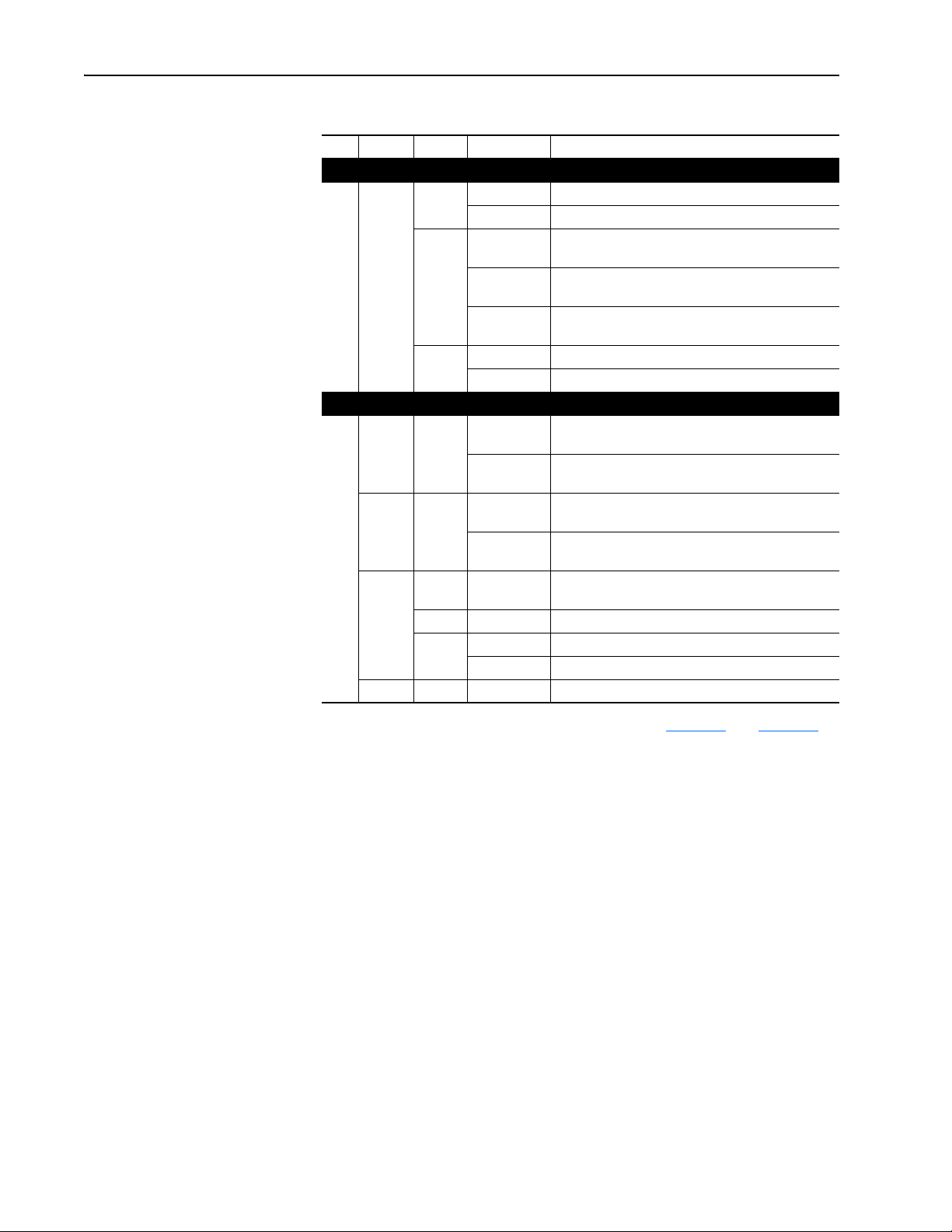
Related Documentation
Resource Description
PowerFlex 7-Class DPI (Drive Peripheral Interface) Network Communication Adapter Installation
Instructions, publication 20COMM-IN004
Connected Components Workbench website http://www.ab.com/support/abdrives/webupdate/
software.html, and online help
DriveExplorer website http://www.ab.com/drives/driveexplorer
DriveExecutive website http://www.ab.com/drives/drivetools
PowerFlex 20-HIM-A3/-A5/-C3S/-C5S HIM Quick Reference, publication 20HIM-QR001
PowerFlex 20-HIM-A6/C6S HIM (Human Interface Module) User Manual, publication 20HIM-UM001
PowerFlex 70 User Manual, publication 20A-UM001
PowerFlex 70/700 Reference Manual, publication PFLEX-RM001
PowerFlex 70 Enhanced Control and 700 Vector Control Reference Manual, publication PFLEX-RM004
PowerFlex 700 Series A User Manual, publication 20B-UM001
PowerFlex 700 Series B User Manual, publication 20B-UM002
PowerFlex 70/700 Reference Manual, publication PFLEX-RM001
PowerFlex 70 Enhanced Control and 700 Vector Control Reference Manual, publication PFLEX-RM004
PowerFlex 700H Installation Instructions, publication PFLEX-IN006
PowerFlex 700H Programming Manual, publication 20C-PM001
PowerFlex 700S w/Phase I Control Installation Manual (Frames 1…6), publication 20D-IN024
PowerFlex 700S w/Phase I Control Installation Manual (Frames 9 and 10), publication PFLEX-IN006
PowerFlex 700S w/Phase I Control User Manual (All Frame Sizes), publication 20D-UM001
PowerFlex 700S w/Phase I Control Reference Manual, publication PFLEX-RM002
PowerFlex 700S w/Phase II Control Installation Manual (Frames 1…6), publication 20D-IN024
PowerFlex 700S w/Phase II Control Installation Manual (Frames 9…14), publication PFLEX-IN006
PowerFlex 700S w/Phase II Control Programming Manual (All Frame Sizes), publication 20D-PM001
PowerFlex 700S w/Phase II Control Reference Manual, publication PFLEX-RM003
(1)
(1)
(1)
Information on using PowerFlex 20-HIM-A3, 20-HIM-A5,
, and online help
, and online help
Information on installing PowerFlex
Communication Adapters.
Information on the Connected Components Workbench
software tool—and includes a link for free software download.
Information on using the DriveExplorer™ software tool.
Information on using the DriveExecutive™ software tool.
20-HIM-C3S, and 20-HIM-C5S HIMs.
Information on installing and using PowerFlex 20-HIM-A6 and
20-HIM-C6S HIMs.
Information on installing and programming PowerFlex 70
standard control and enhanced control drives.
Information on installing and programming PowerFlex 700
standard control and vector control Series A drives, and
PowerFlex 700 vector control Series B drives.
Information on installing and programming PowerFlex 700H
drives.
Information on installing and programming PowerFlex 700S
drives.
®
20-COMM-x Network
20-COMM-L LonWorks Adapter User Manual
Publication 20COMM-UM008B-EN-P
Page 9

About This Manual P-3
Resource Description
PowerFlex 700L User Manual, publication 20L-UM001 Information on installing and programming PowerFlex 700L
PowerFlex 750-Series Drive Installation Instructions, publication 750-IN001
PowerFlex 750-Series Drive Programming Manual, publication 750-PM001
20-750-20COMM and 20-750COMM-F1 Communication Carrier Cards Installation Instructions,
publication 750COM-IN001
PowerFlex Digital DC Drive User Manual, publication 20P-UM001
LonMark Layers 1-6 Interoperability Guidelines, Appendix A ‘Cable Requirements for the TP/FT-10
Channel’ at www.echelon.com
(1)
The online help is installed with the software.
Documentation can be obtained online at http://
literature.rockwellautomation.com. To order paper copies of technical
documentation, contact your local Rockwell Automation distributor or sales
representative.
To find your local Rockwell Automation distributor or sales representative,
visit http://www.rockwellautomation.com/locations
For information such as firmware updates or answers to drive-related
questions, go to the Drives Service & Support website at http://
www.ab.com/support/abdrives and click on the Downloads or
Knowledgebase link.
Information on installing and programming PowerFlex Digital
Liquid-Cooled AC drives.
Information on installing and programming PowerFlex
750-Series AC drives.
DC drives.
Information on network cabling guidelines.
.
20-COMM-L LonWorks Adapter User Manual
Publication 20COMM-UM008B-EN-P
Page 10

P-4 About This Manual
Notes:
20-COMM-L LonWorks Adapter User Manual
Publication 20COMM-UM008B-EN-P
Page 11
Chapter 1
Getting Started
The adapter is intended for installation into a PowerFlex 7-Class drive and
is used for network communication.
When used with PowerFlex 750-Series drives, the 20-COMM-L adapter
must have firmware revision 1.007 or later, and must be installed using the
20-750-20COMM or 20-750-20COMM-F1 Communication Carrier Card.
There are operating limitations and this manual does not include
information on using the 20-COMM-L adapter with PowerFlex 750-Series
drives.
Topic Page
Components
Features 1-2
Compatible Products 1-3
Required Equipment 1-3
Safety Precautions 1-5
Quick Start 1-6
1-1
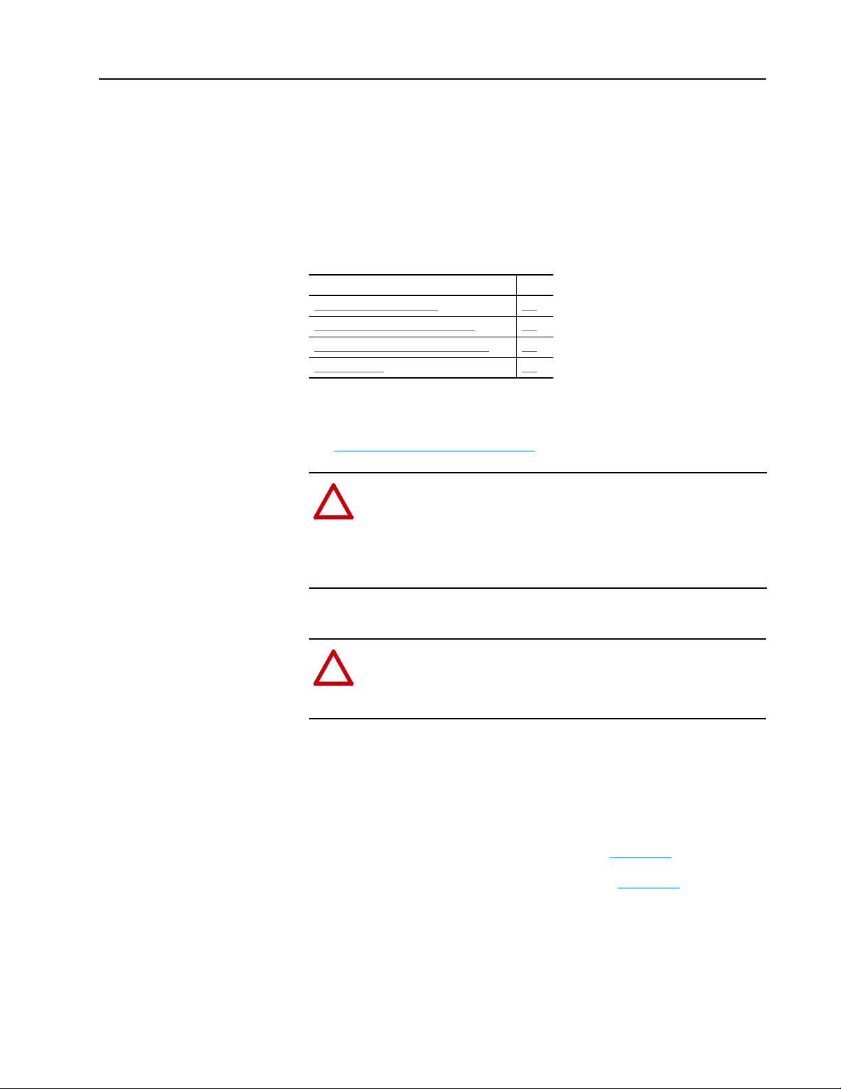
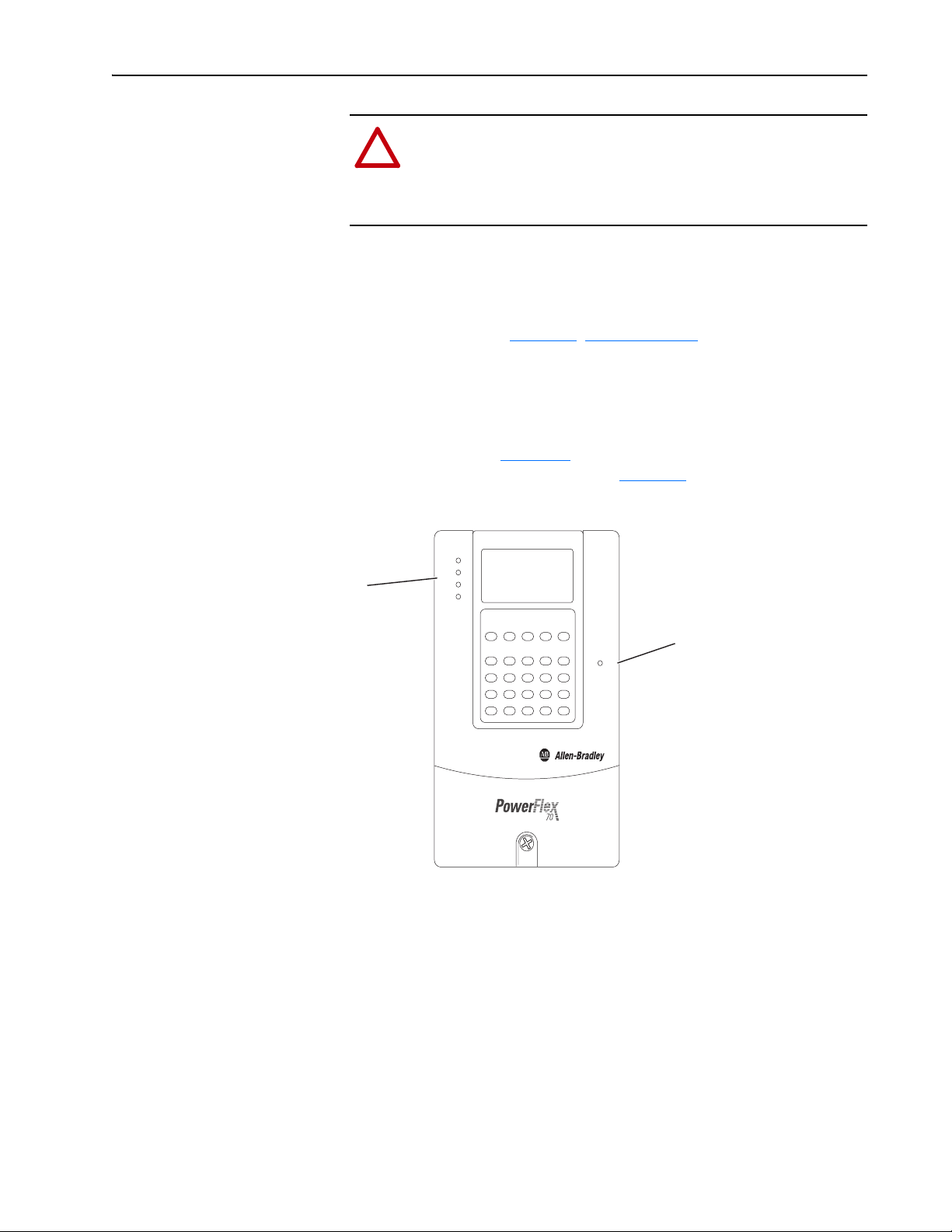
Components
➊
➋
➌
Item Part Description
Status Indicators Three status indicators that indicate the status of the DPI, adapter, and
➊
DPI Connector A 20-pin, single-row shrouded male header. An Internal Interface cable
➋
Terminal Block A 6-screw terminal block to connect the LonWorks network cable.
➌
network connection. See Chapter 5
is connected to this connector and a connector on the drive.
, Troubleshooting.
20-COMM-L LonWorks Adapter User Manual
Publication 20COMM-UM008B-EN-P
Page 12

1-2 Getting Started
Features
The features of the adapter include the following:
• Typical mounting in a PowerFlex 7-Class drive.
• Captive screws to secure and ground the adapter to the drive.
• Compatibility with various configuration tools to configure the adapter
and connected host drive, including the following tools:
– PowerFlex HIM (Human Interface Module) on the drive, if available
– Connected Components Workbench software, version 1.02 or later
– DriveExplorer software, version 2.01 or later
– DriveExecutive software, version 3.01 or later
• Status indicators that report the status of the drive communications, the
adapter, and network. They are visible when the drive cover is open or
closed.
• Parameter-configured I/O (Logic Command/Reference and up to four
pairs of Datalinks) to accommodate application requirements.
• Support for LonMark Functional Profile: ‘Variable Speed Motor Drive:
6010’.
• Sending and receiving Datalink data.
• Read/write access to monitor/configure parameter values of the drive and
connected peripherals over the network.
• User-defined fault actions to determine how the adapter and connected
drive respond to the following:
– I/O messaging communication disruptions (Comm Flt Action)
– Offline/disable occurrences (Idle Flt Action)
• LonMark conformance tested.
• Access to any PowerFlex drive and its connected peripherals on the
network to which the adapter is connected.
20-COMM-L LonWorks Adapter User Manual
Publication 20COMM-UM008B-EN-P
Page 13

Getting Started 1-3
Compatible Products
Required Equipment
At the time of publication, the adapter is compatible with the following
products:
• PowerFlex 70 drives with standard or enhanced control • PowerFlex 750-Series drives
• PowerFlex 700 drives with standard or vector control • PowerFlex Digital DC drives
• PowerFlex 700H drives • SMC™ Flex smart motor controllers
• PowerFlex 700S drives with Phase I or Phase II control • SMC-50 smart motor controllers
• PowerFlex 700L drives with 700 vector control or 700S control
(1)
The 20-COMM-L adapter can be used with PowerFlex 750-Series drives, but the adapter must have firmware revision
1.007 or later. Also, the adapter has the following limitations and differences:
- Only the first 16 bits of the Logic Command and Logic Status words are used.
- Only drive Ports 0…6 are supported.
- Controller must be capable of reading/writing 32-bit floating point (REAL) values.
- Speed Reference/Feedback scaling are Hz (or RPM) x 1000 (depending on the setting of drive
parameter 300 - [Speed Units].
Please see the PowerFlex 750-Series AC Drives Programming Manual, publication 750-PM001, for drive parameter
information.
Some of the equipment that is required for use with the adapter is shipped
with the adapter, but some you must supply yourself.
(1)
Equipment Shipped with the Adapter
When you unpack the adapter, verify that the package includes the
following:
❑ One 20-COMM-L adapter
❑ One 2.54 cm (1 in.) long and one 15.24 cm (6 in.) long Internal
Interface cable (only one cable is needed to connect the adapter to the
drive; for which cable to use, see Figure 2.1 on page 2-2
❑ One 6-screw terminal block (connected to the adapter)
❑ Resource files on digital media
❑ One PowerFlex 7-Class DPI (Drive Peripheral Interface) Network
Communication Adapter Installation Instructions, publication
20COMM-IN004
TIP: When mounting the 20-COMM-L adapter in a PowerFlex 750-Series
drive, you must use a 20-750-20COMM or 20-750-20COMM-F1
Communication Carrier Card, publication 750COM-IN001—and the
20-COMM-L adapter must have firmware revision 1.007 or later.
)
20-COMM-L LonWorks Adapter User Manual
Publication 20COMM-UM008B-EN-P
Page 14

1-4 Getting Started
User-Supplied Equipment
To install and configure the adapter, you must supply the following:
❑ A small flathead screwdriver
❑ Network-specific cable to connect the adapter to the network. See the
network-specific documentation for the cable recommendations and
requirements.
❑ Drive and adapter configuration tool, such as the following:
– PowerFlex 20-HIM-xx HIM
– Connected Components Workbench software, version 1.02 or later
Connected Components Workbench is the recommended
stand-alone software tool for use with PowerFlex drives. You can
obtain a free copy by:
• Internet download at http://www.ab.com/support/abdrives/
webupdate/software.html
• Requesting a DVD at http://www.ab.com/onecontact/controllers/
micro800/
Your local distributor may also have copies of the DVD available.
Connected Components Workbench software cannot be used to
configure SCANport-based drives or Bulletin 160 drives.
– DriveExplorer software, version 2.01 or later
This software tool has been discontinued and is now available as
freeware at http://www.ab.com/support/abdrives/webupdate/
software.html. There are no plans to provide future updates to this
tool and the download is being provided ‘as-is’ for users that lost
their DriveExplorer CD, or need to configure legacy products not
supported by Connected Components Workbench software.
– DriveExecutive software, version 3.01 or later
A Lite version of DriveExecutive software ships with RSLogix
5000, RSNetWorx MD, FactoryTalk AssetCentre, and
ItelliCENTER software. All other versions are purchasable items:
• 9303-4DTE01ENE Drive Executive software
• 9303-4DTS01ENE DriveTools SP Suite (includes
DriveExecutive and DriveObserver software)
• 9303-4DTE2S01ENE DriveExecutive software upgrade to
DriveTools SP Suite (adds DriveObserver software)
20-COMM-L LonWorks Adapter User Manual
Publication 20COMM-UM008B-EN-P
DriveExecutive software updates (patches, and so forth) can be
obtained at http://www.ab.com/support/abdrives/webupdate/
software.html. It is highly recommended that you periodically check
for and install the latest update.
❑ LonMaker configuration software
❑ A computer connection to the LonWorks network
Page 15
Getting Started 1-5
!
!
!
!
!
!
!
Safety Precautions
Please read the following safety precautions carefully.
ATTENTION: Risk of injury or death exists. The PowerFlex
drive can contain high voltages that can cause injury or death.
Remove all power from the PowerFlex drive, and then verify
power has been discharged before installing or removing an
adapter.
ATTENTION: Risk of injury or equipment damage exists. Only
personnel familiar with drive and power products and the
associated machinery should plan or implement the installation,
startup, configuration, and subsequent maintenance of the product
using an adapter. Failure to comply may result in injury and/or
equipment damage.
ATTENTION: Risk of equipment damage exists. The adapter
contains electrostatic discharge (ESD) sensitive parts that can be
damaged if you do not follow ESD control procedures. Static
control precautions are required when handling the adapter. If you
are unfamiliar with static control procedures, see Guarding
Against Electrostatic Damage, publication 8000-4.5.2.
ATTENTION: Risk of injury or equipment damage exists. DPI
or SCANport host products must not be directly connected
together using 1202 cables. Unpredictable behavior due to timing
and other internal procedures can result if two or more devices are
connected this way.
ATTENTION: Risk of injury or equipment damage exists. If the
adapter is transmitting control I/O to the drive, the drive can fault
when you reset the adapter. Determine how your drive will
respond before resetting an adapter.
ATTENTION: Risk of injury or equipment damage exists.
Parameter 6 - [Comm Flt Action] lets you determine the action
of the adapter and connected drive if I/O communication is
disrupted. By default, this parameter faults the drive. You can set
this parameter so that the drive continues to run, however, take
precautions to verify that the setting of this parameter does not
create a risk of injury or equipment damage. When
commissioning the drive, verify that your system responds
correctly to various situations (for example, a disconnected cable
or a faulted controller).
ATTENTION: Risk of injury or equipment damage exists.
Parameter 7 - [RcvHrtBeat Time] lets you determine how long
it will take the adapter to detect network communication losses.
By default, this parameter sets the time to 120 seconds. You can
set it so that the duration is shorter, longer, or disabled. When set
to disabled, this also disables Parameter 6 - [Comm Flt Action].
Therefore, a communication fault action is ignored. Take
precautions to verify that the setting does not create a risk of
injury or equipment damage. When commissioning the drive,
verify that your system responds correctly to various situations
(for example, a disconnected cable).
20-COMM-L LonWorks Adapter User Manual
Publication 20COMM-UM008B-EN-P
Page 16
1-6 Getting Started
!
!
ATTENTION: Risk of injury or equipment damage exists.
When a system is configured for the first time, there can be
unintended or incorrect machine motion. Disconnect the motor
from the machine or process during initial system testing.
ATTENTION: Risk of injury or equipment damage exists. The
examples in this publication are intended solely for purposes of
example. There are many variables and requirements with any
application. Rockwell Automation does not assume responsibility
or liability (to include intellectual property liability) for actual use
of the examples shown in this publication.
Quick Start
This section is provided to help experienced users quickly start using the
adapter. If you are unsure how to complete a step, see the referenced chapter.
Step Action See
1 Review the safety precautions for the adapter. Throughout This Manual
2 Verify that the PowerFlex drive is properly installed. Drive User Manual
PowerFlex 7-Class DPI
Network Communication
Adapter Installation
Instructions, publication
20COMM-IN004) and
Chapter 2
Installing the Adapter
Chapter 2
Installing the Adapter
Chapter 3
Configuring the Adapter
Chapter 4,
Configuring the
LonWorks Network
3 Install the adapter.
a. Verify that the PowerFlex drive is not powered.
b. Connect the adapter to the drive using the Internal Interface
cable.
c. Use the captive screws to secure and ground the adapter to
the drive.
d. Connect the adapter to the network using a network cable.
NOTE: When installing the adapter in a PowerFlex 750-Series
drive, see the 20-750-20COMM and 20-750-20COMM-F1
Communication Carrier Cards Installation Instructions,
publication 750COM-IN001, supplied with the card.
4 Apply power to the adapter.
a. Verify that the adapter is installed correctly.
The adapter receives power from the drive.
b. Apply power to the drive.
The status indicators should be green. If they flash red, there
is a problem. See Chapter 5
c. Configure and verify key drive parameters.
5 Configure the adapter for your application.
Set adapter parameters for the following functions as required by
your application:
• I/O configuration
• Fault action
6 Set up the network to communicate with the adapter.
Use a network tool, such as LonMaker, to configure the adapter
on the network.
, Troubleshooting.
,
,
,
20-COMM-L LonWorks Adapter User Manual
Publication 20COMM-UM008B-EN-P
Page 17
Chapter 2
!
!
Installing the Adapter
This chapter provides instructions for installing the adapter in a PowerFlex
7-Class drive.
Topic Page
Preparing for an Installation
Connecting the Adapter to the Drive 2-1
Connecting the Adapter to the Network 2-4
Applying Power 2-5
2-1
Preparing for an Installation
Connecting the Adapter to the Drive
Before installing the adapter, verify that you have all required equipment.
See Required Equipment
ATTENTION: Risk of equipment damage exists. The adapter
contains electrostatic discharge (ESD) sensitive parts that can be
damaged if you do not follow ESD control procedures. Static
control precautions are required when handling the adapter. If you
are unfamiliar with static control procedures, see Guarding
Against Electrostatic Damage, publication 8000-4.5.2.
ATTENTION: Risk of injury or death exists. The PowerFlex
drive can contain high voltages that can cause injury or death.
Remove power from the drive, and then verify power has been
discharged before installing or removing the adapter.
1. Remove power from the drive.
2. Use static control precautions.
3. Remove the drive cover or open the drive door.
on page 1-3.
4. Connect the Internal Interface cable to the DPI port on the drive and
then to the DPI connector on the adapter (see Figure 2.1
5. Secure and ground the adapter to the drive (see Figure 2.2
following:
– On a PowerFlex 70 drive, fold the Internal Interface cable behind the
adapter and mount the adapter on the drive using the four captive screws.
– On a PowerFlex 700, PowerFlex 700H or PowerFlex 700S drive,
mount the adapter on the drive using the four captive screws.
).
) by doing the
20-COMM-L LonWorks Adapter User Manual
Publication 20COMM-UM008B-EN-P
Page 18
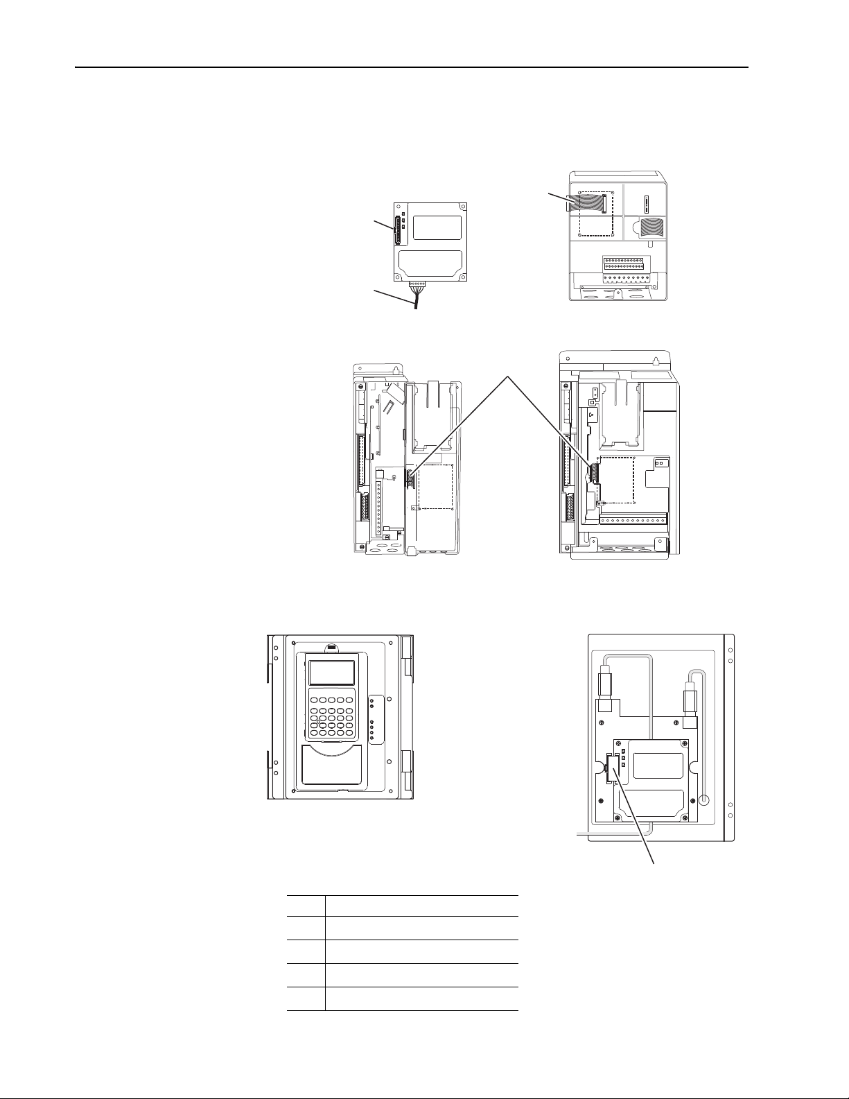
2-2 Installing the Adapter
20-COMM-L Adapter
PowerFlex 700 Frames 0 and 1
PowerFlex 700S Frames 0 and 1
PowerFlex 70 - All Frames
PowerFlex 700 Frames 2 and Larger
PowerFlex 700S Frames 2 through 6
HIM panel opens for
access to the DPI
interface. To open HIM
panel, remove screws
on left side of HIM
panel and swing open.
PowerFlex 700H Frames 9 and Larger
PowerFlex 700S Frames 9 and Larger
Important: Tighten all screws to properly ground the adapter.
Recommended torque is 0.9 N•m (8.0 lb•in).
Figure 2.1 DPI Ports and Internal Interface Cables
➊
➋
➌
➍
Item Description
15.24 cm (6 in.) Internal Interface cable
➊
DPI Connector
➋
Network cable
➌
2.54 cm (1 in.) Internal Interface cable
➍
X2
X1
➍
20-COMM-L LonWorks Adapter User Manual
Publication 20COMM-UM008B-EN-P
Page 19
X1
X2
Drive
Adapter
Internal Interface Cable
folded behind the adapter
and in front of the drive.
PowerFlex 70 - All Frame Sizes
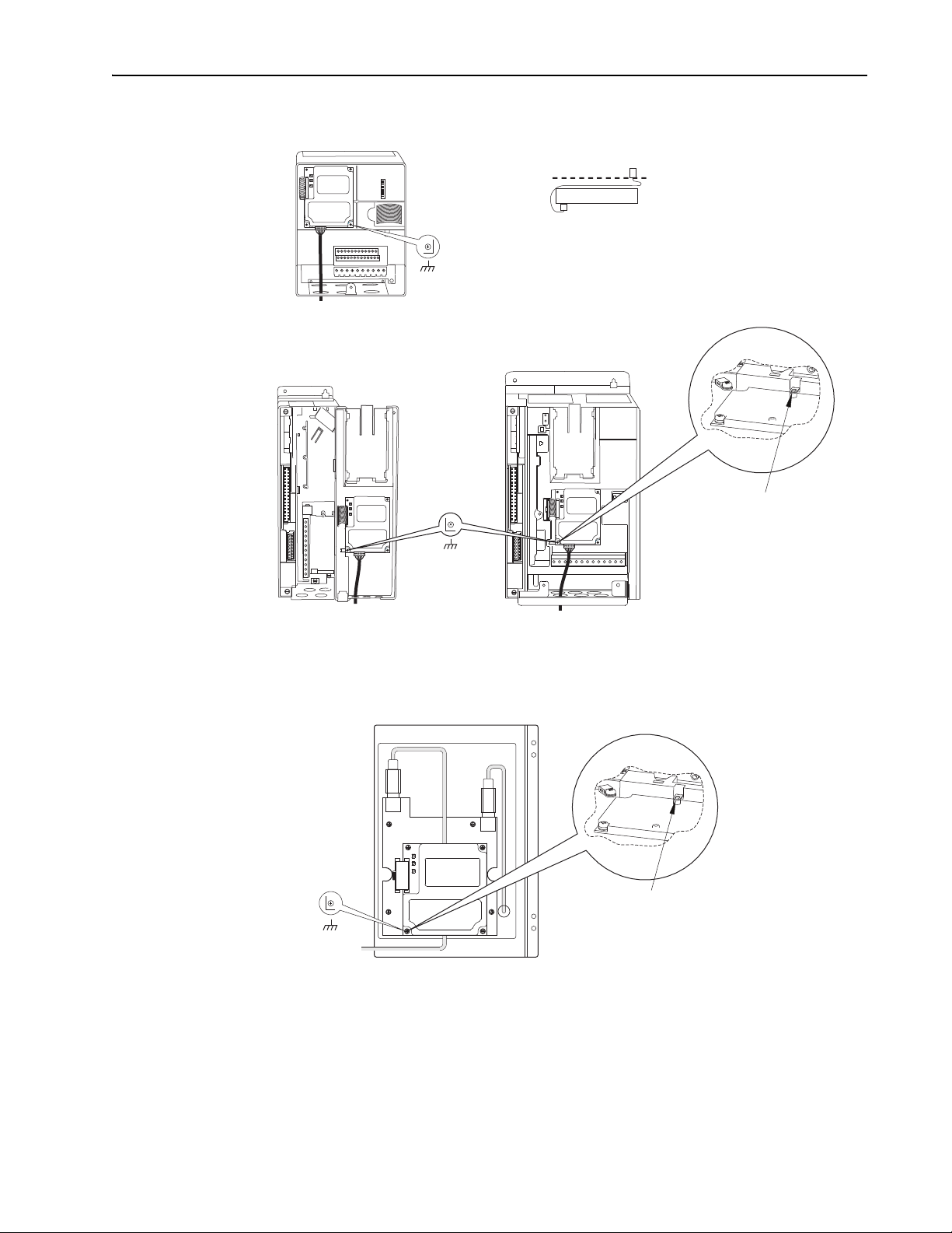
(Adapter mounts in drive.)
Verify metal ground tab is bent 90° and
is under the adapter before tightening
screw. After tightening the screw, verify
continuity exists between the head of
the screw and drive ground.
Ground Tab Detail
PowerFlex 700 Frames 0 and 1
PowerFlex 700S Frames 0 and 1
(Adapter mounts on door.)
0.9 N•m
(8.0 lb•in)
4 Places
PowerFlex 700 Frames 2 and Larger
PowerFlex 700S Frames 2 through 6
(Adapter mounts in drive.)
0.9 N•m
(8.0 lb•in)
4 Places
Verify metal ground tab is bent 90° and
is under the adapter before tightening
screw. After tightening the screw, verify
continuity exists between the head of
the screw and drive ground.
0.9 N•m
(8.0 lb•in)
4 Places
PowerFlex 700H Frames 9 and Larger
PowerFlex 700S Frames 9 and Larger
(Adapter mounts behind HIM panel.)
Ground Tab Detail
Installing the Adapter 2-3
Figure 2.2 Mounting and Grounding the Adapter
NOTE: When installing the adapter in a PowerFlex 750-Series drive, see to
the 20-750-20COMM and 20-750-20COMM-F1 Communication Carrier
Cards Installation Instructions, publication 750COM-IN001, supplied with
the card.
20-COMM-L LonWorks Adapter User Manual
Publication 20COMM-UM008B-EN-P
Page 20
2-4 Installing the Adapter
!
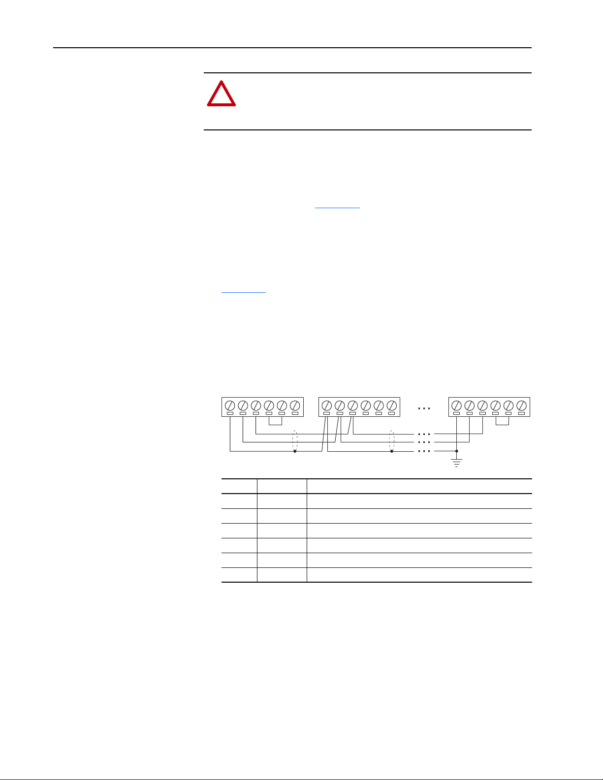
Connecting the Adapter to the Network
ATTENTION: Risk of injury or death exists. The PowerFlex
drive can contain high voltages that can cause injury or death.
Remove power from the drive, and then verify power has been
discharged before installing or removing the adapter.
1. Remove power from the drive.
2. Use static control precautions.
3. Route the LonWorks cable from the network through the bottom of the
PowerFlex drive (see Figure 2.2
See the LonMark Layers 1-6 Interoperability Guidelines, Appendix A
‘Cable Requirements for the TP/FT-10 Channel’ for cable
recommendations and requirements.
4. Connect a 6-pin linear plug to the network cable.
Figure 2.3
functions.
Figure 2.3 Example Wiring of Bus Topology with Shield
shows a wiring example, and terminal names and their
Node 1 Node 2 Node "n"
).
NET B
TERM BUS
TERM COM
TERM FT
(1)
Noise mitigation
NET A
SHIELD
NET B
TERM BUS
(2)
TERM COM
TERM FT
SHIELD
(3)
topology networks
(4)
topology networks
NET A
SHIELD
Terminal Name Function
1SHIELD
2 NET A Network connection, polarity insensitive
3 NET B Network connection, polarity insensitive
4 TERM BUS Connect to TERM COM for termination of Bus
5 TERM COM Termination common
6 TERM FT Connect to TERM COM for termination of Free
(1)
We recommend using shielded network cable. This shield must be grounded at one point on the network
using a 470K ohm, 1/4 watt, ≤ 10% metal film resistor.
(2)
For noise mitigation, do not run LON trunk lines in close proximity to drive or equipment power distribution
feeds.
(3)
To terminate a Bus topology network (one termination at each end of the network), connect TERM COM to
TERM BUS.
(4)
To terminate a Free topology network (one termination per segment), connect TERM COM to TERM FT.
NET A
NET B
TERM COM
TERM BUS
TERM FT
5. Insert the 6-pin linear plug into the mating adapter terminal block.
20-COMM-L LonWorks Adapter User Manual
Publication 20COMM-UM008B-EN-P
Page 21
Installing the Adapter 2-5
!
Applying Power
ATTENTION: Risk of equipment damage, injury, or death
exists. Unpredictable operation can occur if you fail to verify that
parameter settings are compatible with your application. Verify
that settings are compatible with your application before applying
power to the drive.
Install the drive cover or close the drive door, and apply power to the drive.
The adapter receives its power from the connected drive. When you apply
power to the adapter for the first time, its topmost ‘PORT’ status indicator
should be steady green or flashing green after an initialization. If it is red,
there is a problem. See Chapter 5
Start-Up Status Indications
Status indicators for the drive and communication adapter can be viewed on
the front of the drive (Figure 2.4
start-up status indications are shown in Table 2. A
Figure 2.4 Drive and Adapter Status Indicators (location on drive may vary)
PORT
MOD
➋
NET A
NET B
, Troubleshooting.
) after power has been applied. Possible
.
➊
STS
20-COMM-L LonWorks Adapter User Manual
Publication 20COMM-UM008B-EN-P
Page 22
2-6 Installing the Adapter
Table 2.A Drive and Adapter Start-Up Status Indications
Item Name Color State Description
Drive STS Indicator
STS
➊
(Status)
PORT Green Flashing Normal operation. The adapter is establishing an I/O
➋
MOD Green Flashing Normal operation. The adapter is operating but is not
NET A Off n/a Normal operation. The adapter/drive node is
NET B — — Not used by LonWorks adapter.
Green Flashing Drive ready but not running, and no faults are present.
Steady Drive running, no faults are present.
Yellow Flashing,
drive stopped
Flashing,
drive running
Steady,
drive running
Red Flashing A fault has occurred.
Steady A non-resettable fault has occurred.
Steady Normal operation. The adapter is properly connected
Steady Normal operation. The adapter is operating and
Red Flashing WINK command received.
Green Flashing The adapter/drive node is not configured.
Steady The adapter/drive node has no application program.
An inhibit condition exists – the drive cannot be
started. Check drive Parameter 214 - [Start Inhibits].
An intermittent type 1 alarm condition is occurring.
Check drive Parameter 211 - [Drive Alarm 1].
A continuous type 1 alarm condition exists. Check
drive Parameter 211 - [Drive Alarm 1].
Adapter Status Indicators
connection to the drive. It will turn steady green or red.
and communicating with the drive.
transferring I/O data to a controller.
transferring I/O data to a controller.
configured.
For more details on status indicator operation, see page 5-2 and page 5-3.
Configuring and Verifying Key Drive Parameters
The PowerFlex 7-Class drive can be separately configured for the control
and Reference functions in various combinations. For example, you could
set the drive to have its control come from a peripheral or terminal block
with the Reference coming from the network. Or you could set the drive to
have its control come from the network with the Reference coming from
another peripheral or terminal block. Or you could set the drive to have both
its control and Reference come from the network.
The following steps in this section assume that the drive will receive the
Logic Command and Reference from the network.
1. Use drive Parameter 090 - [Speed Ref A Sel] to set the drive speed
Reference to ‘22’ (DPI Port 5).
2. If hard-wired discrete digital inputs are not used to control the drive,
verify that unused digital input drive Parameters 361 - [Dig In1 Sel] and
362 - [Dig In2 Sel] are set to ‘0’ (Not Used).
20-COMM-L LonWorks Adapter User Manual
Publication 20COMM-UM008B-EN-P
Page 23

Installing the Adapter 2-7
3. Verify that drive Parameter 213 - [Speed Ref Source] is reporting that
the source of the Reference to the drive is ‘22’ (DPI Port 5).
This ensures that any Reference commanded from the network can be
monitored by using drive Parameter 002 - [Commanded Speed]. If a
problem occurs, this verification step provides the diagnostic capability
to determine whether the drive/adapter or the network is the cause.
TIP: For PowerFlex 750-Series drives, use drive Parameter 545 [Speed Ref A Sel] to set the drive speed Reference:
a. Set the Port field to ‘Port 0 - PowerFlex 75x’.
b. Set the Parameter field to point to the port in which the
20-COMM-L adapter/20-750-20COMM Communication Carrier
Card are installed (for example, ‘876 - Port 6 Reference’).
The number ‘876’ in the Parameter filed of the example is the
parameter in the drive that points to the port.
20-COMM-L LonWorks Adapter User Manual
Publication 20COMM-UM008B-EN-P
Page 24

2-8 Installing the Adapter
Notes:
20-COMM-L LonWorks Adapter User Manual
Publication 20COMM-UM008B-EN-P
Page 25
Chapter 3
Configuring the Adapter
This chapter provides instructions and information for setting the
parameters to configure the adapter.
Topic Page
Configuration Tools
Using the PowerFlex 7-Class HIM to Access Parameters 3-2
Setting the I/O Configuration 3-3
Setting a Communication Fault Action 3-4
Setting an Idle Fault Action 3-5
Resetting the Adapter 3-6
Viewing the Adapter Status Using Parameters 3-6
Updating the Adapter Firmware 3-7
3-1
Configuration Tools
For a list of parameters, see Appendix
definitions of terms in this chapter, see the Glossary
The adapter stores parameters and other information in its own nonvolatile
storage (NVS) memory. You must, therefore, access the adapter to view and
edit its parameters. The following tools can be used to access the adapter
parameters.
Tool See
PowerFlex 7-Class HIM page 3-2
Connected Components Workbench
software, version 1.02 or later
DriveExplorer software,
version 2.01 or later
DriveExecutive software,
version 3.01 or later
B, Adapter Parameters. For
.
http://www.ab.com/support/abdrives/webupdate/
software.html, or online help (installed with the software)
http://www.ab.com/drives/driveexplorer
DriveExplorer online help (installed with the software)
http://www.ab.com/drives/drivetools
DriveExecutive online help (installed with the software)
, or
, or
20-COMM-L LonWorks Adapter User Manual
Publication 20COMM-UM008B-EN-P
Page 26
3-2 Configuring the Adapter
ALT
Sel
F-> Stopped Auto
0.00 Hz
Main Menu:
Diagnostics
Parameter
Device Select
Por t 5 Device
20-COMM-L
Main Menu:
Diagnostics
Parameter
Device Select
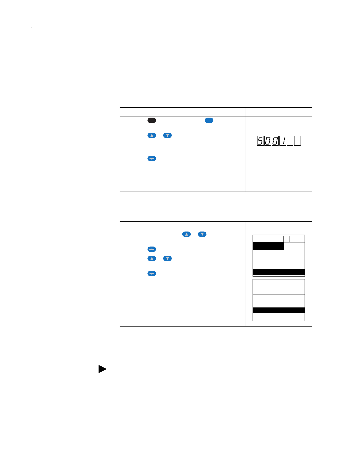
Using the PowerFlex 7-Class HIM to Access Parameters
If your drive has either an LED or LCD HIM (Human Interface Module), it
can be used to access parameters in the adapter as shown below. We
recommend that you read through the steps for your HIM before performing
the sequence. For additional information, see the drive documentation or the
PowerFlex 7-Class HIM Quick Reference, publication 20HIM-QR001.
Using an LED HIM
Step Example Screens
1. Press the key and then the Device (Sel) key to
display the Device Screen.
2. Press the or key to scroll to the adapter.
Letters represent files in the drive, and numbers represent
ports. The adapter is usually connected to port 5.
3. Press the (Enter) key to enter your selection.
A parameter database is constructed, and then the first
parameter is displayed.
4. Edit the parameters using the same techniques that you use
to edit drive parameters.
20-COMM-L LonWorks Adapter User Manual
Publication 20COMM-UM008B-EN-P
Using an LCD HIM
Step Example Screens
1. In the main menu, press the or key to scroll to
Device Select.
2. Press the (Enter) key to enter your selection.
3. Press the or key to scroll to the adapter
(20-COMM-L).
4. Press the (Enter) key to select the adapter.
A parameter database is constructed, and then the main
menu for the adapter is displayed.
5. Edit the parameters using the same techniques that you use
to edit drive parameters.
NOTE: All configuration procedures throughout this chapter use the
PowerFlex 7-Class LCD HIM to access parameters in the adapter and show
example LCD HIM screens.
TIP: When using a PowerFlex 20-HIM-A6 or 20-HIM-C6S HIM, see its
User Manual, publication 20HIM-UM001.
Page 27

Configuring the Adapter 3-3
Bit Description
0 Logic Command/Reference (Default)
1 Datalink A
2 Datalink B
3 Datalink C
4 Datalink D
5…15 Not Used
Por t 5 Device
20-COMM-L
Parameter #: 09
DPI I/O Cfg
xxxxxxxxxxx0000
1
Cmd/Ref b00
Setting the I/O Configuration
The I/O configuration determines the data that is sent to and from the drive.
Logic Command/Status, Reference/Feedback, and Datalinks may be
enabled or disabled. (Datalinks allow you to read/write directly to
parameters in the drive using implicit I/O.) A ‘1’ enables the I/O and a ‘0’
disables the I/O.
1. Set the bits in Parameter 9 - [DPI I/O Cfg].
Bit 0 is the right-most bit. It is highlighted above and equals ‘1’.
2. If Logic Command/Reference is enabled, configure the parameters in
the drive to accept the Logic Command and Reference from the adapter.
For example, set Parameter 90 - [Speed Ref A Sel] in a PowerFlex 70 or
700 drive to ‘22’ (DPI Port 5) so that the drive uses the Reference from
the adapter. Also, verify that the mask parameters (for example,
Parameter 276 - [Logic Mask]) in the drive are configured to receive the
desired logic from the adapter. See the documentation for your drive for
details.
3. If you enabled one or more Datalinks, configure parameters in the drive
4. Reset the adapter (see Resetting the Adapter
The adapter is ready to receive I/O.
to determine the source and destination of data in the Datalinks.
When using Datalinks, up to 8 drive [Data In xx] parameters
(300…307) and/or up to 8 [Data Out xx] parameter (310…317) must be
assigned to point to the appropriate drive parameters for your
application. Also, verify that the LonWorks adapter is the only adapter
using the enabled Datalinks.
on page 3-6).
20-COMM-L LonWorks Adapter User Manual
Publication 20COMM-UM008B-EN-P
Page 28

3-4 Configuring the Adapter
!
Por t 5 Device
20-COMM-L
Parameter #: 06
Comm Flt Action
0
Fault
Value Action
(1)
(1)
An actual action taken requires Parameter 7 - [RcvHrtBeat Time] to
have a value greater than ‘0’.
Description
0 Fault The drive is faulted and stopped.
(Default)
1 Stop The drive is stopped, but not faulted.
2 Zero Data The drive is sent ‘0’ values for data.
This does not command a stop.
3 Hold Last The drive continues in its present state.
4 Send Flt Cfg The drive is sent the data that you set in
the fault configuration parameters
(Parameters 11 - [Flt Cfg Logic]
through 20 - [Flt Cfg D2 In]).
Setting a Communication Fault Action
By default, when I/O communication is disrupted (for example, a cable is
disconnected), the drive responds by faulting if it is using I/O from the
network. You can configure a different response to the disrupted I/O
communication by using Parameter 6 - [Comm Flt Action]. The drive will
remain in its present state (for example, a running drive will continue to run)
until the value in Parameter 7 - [RcvHrtBeat Time] has elapsed.
ATTENTION: Risk of injury or equipment damage exists.
Parameter 6 - [Comm Flt Action] and Parameter 7 [RcvHrtBeat Time] let you determine the action of the adapter
and connected drive if I/O communication is disrupted. By
default, Parameter 6 - [Comm Flt Action] faults the drive. You
can set this parameter so that the drive continues to run, however,
take precautions to verify that the setting of this parameter does
not create a risk of injury or equipment damage. When
commissioning the drive, verify that your system responds
correctly to various situations (for example, a disconnected
cable).
Changing the Fault Action
20-COMM-L LonWorks Adapter User Manual
Publication 20COMM-UM008B-EN-P
1. Set the value of Parameter 6 - [Comm Flt Action] to an action that
meets your application requirements.
2. Set the value of Parameter 7 - [RcvHrtBeat Time] to the desired
value.
A setting of ‘0’ disables the fault action and a value greater than ‘0’
enables the fault action. If nviDrvSpeedStpt is not received by the
adapter within the value of Parameter 7 - [RcvHrtBeat Time], the
fault action in Parameter 6 - [Comm Flt Action] will be taken.
Page 29

Por t 5 Device
20-COMM-L
Parameter #: 07
RcvHrtBeat Time
120.0 s
0 <> 3276.7
Default = 120.0 s
Port 5 Device
20-COMM-L
Parameter #: 08
Idle Flt Action
0
Fault
Value Action Description
0 Fault The drive is faulted and stopped.
(Default)
1 Stop The drive is stopped, but not faulted.
2 Zero Data The drive is sent ‘0’ values for data.
This does not command a stop.
3 Hold Last The drive continues in its present state.
4 Send Flt Cfg The drive is sent the data that you set in
the fault configuration parameters
(Parameters 11 - [Flt Cfg Logic]
through 20 - [Flt Cfg D2 In]).
Configuring the Adapter 3-5
Changes to these parameters take effect immediately. A reset is not
required.
Setting the Fault Configuration Parameters
When setting Parameter 6 - [Comm Flt Action] or 8 - [Idle Flt Action] to
‘Send Flt Cfg’, the values in the following parameters are sent to the drive
after an I/O communication fault and/or idle fault occurs. You must set
these parameters to values required by your application.
Parameter Description
11 - [Flt Cfg Logic] A 16-bit value sent to the drive for Logic Command.
12 - [Flt Cfg Ref] A 32-bit value (0…4294967295) sent to the drive as a Reference or Datalink.
13 - [Flt Cfg x1 In]
through
20 - [Flt Cfg x2 In]
Important: If the drive uses a 16-bit Reference or 16-bit Datalinks, the most
significant word of the value must be set to zero (0) or a fault will occur.
Setting an Idle Fault Action
Changes to these parameters take effect immediately. A reset is not
required.
Parameter 8 - [Idle Flt Action] lets you determine the action of the adapter
and connected drive when the node is taken offline.
Changing the Idle Action
Set the value of Parameter 8 - [Idle Flt Action] to an action that meets
your application requirements.
Changes to this parameter take effect immediately. A reset is not required.
20-COMM-L LonWorks Adapter User Manual
Publication 20COMM-UM008B-EN-P
Page 30

3-6 Configuring the Adapter
!
Value Description
0 Ready (Default)
1 Reset Module
2 Set Defaults
Port 5 Device
20-COMM-L
Parameter #: 05
Reset Module
1
Reset Module
Bit
Definition
Not Used
Not Used
Not Used
Datalink D
Datalink C
Datalink B
Datalink A
Cmd/Ref
Default xxx00001
Bit 76543210
0 = I/O disabled
1 = I/O enabled
Setting the Fault Configuration Parameters
See Setting the Fault Configuration Parameters on page 3-5 for details,
which apply to both Parameter 6 - [Comm Flt Action] and Parameter 8 -
[Idle Flt Action].
Resetting the Adapter
Changes to some adapter parameters require that you reset the adapter
before the new settings take effect. You can reset the adapter by power
cycling the drive or by using Parameter 5 - [Reset Module].
ATTENTION: Risk of injury or equipment damage exists. If the
adapter is transmitting control I/O to the drive, the drive can fault
when you reset the adapter. Determine how your drive will
respond before resetting a connected adapter.
Set Parameter 5 - [Reset Module] to ‘1’ (Reset Module).
Figure 3.1 Example Reset Module LCD HIM Screen
When you enter ‘1’ (Reset Module), the adapter will be immediately reset.
When you enter ‘2’ (Set Defaults), the adapter will set all adapter
parameters to their factory-default values. After performing a Set Defaults,
enter ‘1’ (Reset Module) so that the new values take effect. The value of this
parameter will be restored to ‘0’ (Ready) after the adapter is reset.
Viewing the Adapter Status Using Parameters
20-COMM-L LonWorks Adapter User Manual
Publication 20COMM-UM008B-EN-P
The following parameters provide information about the status of the
adapter. You can view these parameters at any time.
Parameter Description
3 - [Ref/Fdbk Size] The size of the Reference/Feedback. It will either be 16 bits or 32 bits. It is
set in the drive and the adapter automatically uses the correct size.
4 - [Datalink Size] The size of the Datalinks. It will either be 16 bits or 32 bits. It is set in the
drive and the adapter automatically uses the correct size.
10 - [DPI I/O Act] The Reference/Feedback and Datalinks used by the adapter. This value is
the same as Parameter 9 - [DPI I/O Cfg] unless the parameter was
changed and the adapter was not reset.
Page 31

Configuring the Adapter 3-7
Updating the Adapter Firmware
The adapter firmware can be updated over the network or serially through a
direct connection from a computer to the drive using a 1203-USB or
1203-SSS serial converter.
When updating firmware over the network, you can use the Allen-Bradley
ControlFLASH software tool, the built-in update capability of
DriveExplorer Lite or Full software, or the built-in update capability of
DriveExecutive software.
When updating firmware through a direct serial connection from a
computer to a drive, you can use the same Allen-Bradley software tools
described above, or you can use HyperTerminal software set to the
X-modem protocol.
To obtain a firmware update for this adapter, go to http://www.ab.com/
support/abdrives/webupdate. This website contains all firmware update files
and associated Release Notes that describe the following items:
• Firmware update enhancements and anomalies
• How to determine the existing firmware revision
• How to update firmware using ControlFLASH, DriveExplorer,
DriveExecutive, or HyperTerminal software.
20-COMM-L LonWorks Adapter User Manual
Publication 20COMM-UM008B-EN-P
Page 32

3-8 Configuring the Adapter
Notes:
20-COMM-L LonWorks Adapter User Manual
Publication 20COMM-UM008B-EN-P
Page 33

Chapter 4
Configuring the LonWorks Network
This chapter provides information about configuring network variables to
access a PowerFlex 7-Class drive over a LonWorks network.
Topic Page
Overview of LonWorks Functionality
Operating the Drive Using a LonMark Profile 4-2
Node Operations 4-4
Network Variable Inputs (NVIs) 4-5
Network Variable Outputs (NVOs) 4-9
Network Configuration Inputs (NCIs) 4-13
Conditions Required for Operation 4-18
Resource Files 4-19
4-1
Overview of LonWorks
Functionality
A network variable is a data item that a particular device application
program expects to get from other devices on a network (an ‘input network
variable’) or expects to make available to other devices on a network (an
‘output network variable’). Data exchange on a LonWorks network is
handled with Standard Network Variable Types (SNVTs), which represent
different types of standard data (for example, temperature, pressure, and
voltage).
When a program writes into one of its output network variables, the new
value of the network variable is propagated across the network to all nodes
with input network variable connected to that output network variable. A
network variable can only be bound to another network variable of the same
type.
Specific network variables are described in sections Network Variable
Inputs (NVIs), Network Variable Outputs (NVOs), and Network
Configuration Inputs (NCIs).
Important: Any changes made with the LCD HIM to a parameter that is
also updated by the network will be overwritten when the next
network update occurs.
20-COMM-L LonWorks Adapter User Manual
Publication 20COMM-UM008B-EN-P
Page 34

4-2 Configuring the LonWorks Network
nviObjRequest
SNVT_obj_request
Mandatory
Network
Variables
Node Object
nvoObjStatus
SNVT_obj_status
nv 1
nv 2
Operating the Drive Using a LonMark Profile
A LonMark profile defines the functional profile for a node communicating
with other nodes. The profile specifies which SNVTs (Standard Network
Variable Types) and SCPTs (Standard Configuration Property Types) are
used, and provides a semantic meaning about the information being
communicated.
When a profile is implemented in a node, it is called a LonMark object. One
node can have several objects implemented. The LonWorks adapter has two
objects: a node object and a drive object. The node object is used to control
the other objects in a node. See Figure 4.1
Figure 4.1 Node Object
The drive object is based on a specific LonMark functional profile
(‘Variable Speed Motor Drive: 6010’), as shown in Figure 4.2
.
.
20-COMM-L LonWorks Adapter User Manual
Publication 20COMM-UM008B-EN-P
Page 35

Figure 4.2 Drive Object
nviDrvSpeedStpt
SNVT_switch
Mandatory
Network
Variables
Optional
Network
Variables
Manufacturer-Defined
Network Variables
Variable Speed Motor
Drive: 6010
nvoDrvSpeed
SNVT_lev_percent
nviDrvSpeedScale
SNVT_lev_percent
nv 1
nv 3
nvoDrvCurnt
SNVT_amp
nv 4
nvoDrvVolt
SNVT_volt
nv 5
nvoDrvPwr
SNVT_power_kilo
nc 50 - nciMaxSpeed
nc 53 - nciMinSpeed
nc 48 - nciRcvHrtBt
nc 49 - nciSndHrtBt
nc 52 - nciMinOutTm
nc 158 - nciNmlSpeed
nc 159 - nciNmlFreq
nc 160 - nciRampUpTm
nc 161 - nciRampDownTM
nc 162 - nciDrvSpeedScale
Configuration Properties
nc RA1 nciParRdAdr
nc RA2 nciParWriAdr
nc RA3 nciParWriData
Manufacturer-Defined
Configuration Properties
nv 6
nvoDrvRunHours
SNVT_time_hour
nvoDrvStatus
SNVT_state
nv 7
nv 8
nvoFreqAct
SNVT_freq_hz
nv 9
nvoFB_config
SNVT_count
nv 10
nvoGenData
UNVT_DATALINK
nv 11
nvoDatalink A1
UNVT_DATALINK
nvoDatalink A2
UNVT_DATALINK
nvoDatalink B1
UNVT_DATALINK
nvoDatalink B2
UNVT_DATALINK
nvoDatalink C1
UNVT_DATALINK
nvoDatalink C2
UNVT_DATALINK
nvoDatalink D1
UNVT_DATALINK
nvoDatalink D2
UNVT_DATALINK
nv 12
nv 13
nv 14
nv 15
nv 16
nv 17
nv 18
nv 19
nviDatalink A1
UNVT_DATALINK
nviDatalink A2
UNVT_DATALINK
nviDatalink B1
UNVT_DATALINK
nviDatalink B2
UNVT_DATALINK
nviDatalink C1
UNVT_DATALINK
nviDatalink C2
UNVT_DATALINK
nviDatalink D1
UNVT_DATALINK
nviDatalink D2
UNVT_DATALINK
nv 21
nv 22
nv 23
nv 24
nv 25
nv 26
nv 27
nv 28
nv 2
nviNv_config
UNVT_DPI_CONFIG
nv 20
Configuring the LonWorks Network 4-3
20-COMM-L LonWorks Adapter User Manual
Publication 20COMM-UM008B-EN-P
Page 36

4-4 Configuring the LonWorks Network
Node Operations
The following sections describe the basics of node operation.
WINK (What is a WINK?)
WINK is a network command that verifies communication with a node. The
NET A status indicator flashes to indicate that a WINK was received. This
LED flashes red according to the following sequence:
• 3 fast flashes
• OFF for 1 second
This sequence is repeated 10 times.
If the Node is Offline
If the node is brought offline it does not accept any NVI (Network Variable
Inputs) settings or update NVOs (Network Variable Outputs). The adapter
uses the setting in Parameter 8 - [Idle Flt Action] and issues a command to
the drive. NCI (Network Configuration Input) variable updates are accepted
but not forwarded to the drive until the node goes online and/or is reset.
If the Node is Online
The node accepts NCI and NVI settings and updates NVOs.
20-COMM-L LonWorks Adapter User Manual
Publication 20COMM-UM008B-EN-P
Page 37

Configuring the LonWorks Network 4-5
Network Variable Inputs (NVIs)
This section provides descriptions of the Network Variable Inputs.
Node Object Request
Va ri abl e: nviObjRequest
Format: SNVT_obj_request
Explanation:
This input enables control commands and updates from the network to
specific objects in the node. The identification number for the node is 0 and
for the drive object is 1. The request functionality is the same for both
objects. The setting of nviObjRequest does not affect the ability of setting
drive speed. The status of the node is reported in nvoObjStatus.
Valid Range for Object ID: 0 or 1
Valid Range for Request:
RQ_UPDATE_STATUS updates nvoObjStatus.
RQ_CLEAR_STATUS clears nvoObjStatus.
RQ_CLEAR_ALARM clears a fault in the drive.
RQ_REPORT_MASK reports supported requests in nvoObjStatus.
RQ_NORMAL and RQ_ENABLE are the normal requests when node
function is normal.
All other requests are not supported, and any attempt to use them sets the
invalid_request bit in nvoObjStatus.
20-COMM-L LonWorks Adapter User Manual
Publication 20COMM-UM008B-EN-P
Page 38

4-6 Configuring the LonWorks Network
Drive Speed Setpoint
Va ri abl e: nviDrvSpeedStpt
Format: SNVT_switch
Explanation:
This network variable input provides a speed reference setpoint. When
nviDrvSpeedStpt.state is set to zero, the drive is stopped.
Valid Range:
State Value Requested Speed
0 n/a STOPPED
10% 0%
1 0.5…100.0% 0.5…100.0%
1 100.0% 100.0%
0xFF n/a AUTO (Default)
Default Value:
Default value is AUTO (state = 0xFF). This value is adapted at power up.
This network variable input uses adapter Parameter 7 - [RcvHrtBeat
Time] if this function is set up for use. The actual drive speed also depends
on nviDrvSpeedScale.
Speed Setpoint Scaling
Va ri abl e: nviDrvSpeedScale
Format: SNVT_lev_percent
Explanation:
This network variable input provides scaling for nviDrvSpdStpt. For
example, if nviDrvSpeedStpt value is 100% and nviDrvSpeedScale value is
-150%, then actual speed setpoint value is -150% (reverse direction at 1.5
times nominal speed).
Valid Range: -163.84…163.83%
Default Value: Defined by nciDrvSpeedScale.
20-COMM-L LonWorks Adapter User Manual
Publication 20COMM-UM008B-EN-P
Page 39

Configuring the LonWorks Network 4-7
Module Configuration
Va ri abl e: nviNV_config
Format: UNVT_DPI_CONFIG
Explanation:
This network variable input provides information on how parameters should
be mapped to network variables. The NVI contains two fields:
• NV_index
• DPI_parameter
To check an already existing configuration, use the following procedures:
A. To check which DPI parameter a network variable is connected to, use
nviNV_config with the following data:
UNVT_DPI_CONF.NV_index = NV_index to check
UNVT_DPI_CONF.DPI_parameter = 65535 (decimal)
B. To check which network variable a DPI parameter is connected to, use
nviNV_config with the following data:
UNVT_DPI_CONF.NV_index = 255 (decimal)
UNVT_DPI_CONF.DPI_parameter = DPI parameter to check
The result of the requests above are placed in nvoFB_config. If there is no
configuration available, 0 (zero) is returned.
Valid Range:
NV_index out: 14…20
LON SNVT NV_Index Default PowerFlex 70/700
Drive Parameter
nvoDrvSpeed 14 1
nvoDrvCurnt 15 3
nvoDrvPwr 17 7
nvoDrvVolt 18 6
nvoDrvRunHours 19 10
nvoDrvFreqAct 20 1
NV_index in: 31…36
LON SNVT NV_Index Default PowerFlex 70/700
Drive Parameter
nciNmlSpeed 31 44
nciMinSpeed 32 81
nciMaxSpeed 33 55
nciRampUpTm 34 140
nciRampDownTime 35 142
nciNmlFreq 36 43
20-COMM-L LonWorks Adapter User Manual
Publication 20COMM-UM008B-EN-P
Page 40

4-8 Configuring the LonWorks Network
Default Value:
This configuration is the default for PowerFlex 70/700 drives. For other
drives, the defaults are 0 and need to be configured prior to network
commissioning. A value of 0 means the variable is disabled and cannot be
used to send/receive data.
Note: It is necessary to configure nciNmlFreq and nciMaxSpeed to operate
the drive from the network.
Datalink Ins
Va ri abl e: nviDatalinkA1
nviDatalinkA2
nviDatalinkB1
nviDatalinkB2
nviDatalinkC1
nviDatalinkC2
nviDatalinkD1
nviDatalinkD2
Format: UNVT_DATALINK
Explanation:
These network variable inputs are used for generic parameter writes by way
of Datalink Ins. To set up a Datalink, configure the adapter according to the
drive manual. All data is sent in raw format; that is, no scaling is performed.
Example:
If PowerFlex 70/700 drive parameter 300 - [Data In A1] is set to ‘101’, it is
pointing to drive parameter 101 - [Preset Speed 1]. Any value written to
nviDatalinkA1 updates drive parameter 101 - [Preset Speed 1] with the
value. A value of ‘100’ equates to 10.0 Hz (note that no scaling is
performed).
20-COMM-L LonWorks Adapter User Manual
Publication 20COMM-UM008B-EN-P
Page 41

Configuring the LonWorks Network 4-9
Network Variable Outputs (NVOs)
This section describes the network variable outputs. No output values are
sent over the network, unless they have changed (except nvoDrvSpeed,
which is sent for the heartbeat functionality, and nvoObjStatus, if update
status is requested).
Node Object Status
Va ri abl e: nvoObjStatus
Format: SNVT_obj_status
Explanation:
This network variable output reports node object status and is updated every
time its status changes (see Node Object Request
Valid Range:
Invalid_ID The node has been asked for an invalid object ID.
Invalid_IDrequest The node has been asked for an unsupported request.
Report_mask Report supported fields.
Comm_failure No contact with DPI.
In_alarm The drive is faulted.
Manual_control The drive is not controlled from the LonWorks peripheral.
on page 4-5).
Drive Status
Va ri abl e: nvoDrvStatus
Format: SNVT_state
Explanation:
This network variable output provides the status of the drive by way of the
Logic Status word (see Appendix
Drive Current
Va ri abl e: nvoDrvCurnt
Format: SNVT_amp
Explanation:
This network variable output provides the drive output current in amps.
Default PowerFlex 70/700 Drive Parameter Mapping:
Parameter 3 - [Output Current]
This can be mapped using the nviNV_config variable.
C).
20-COMM-L LonWorks Adapter User Manual
Publication 20COMM-UM008B-EN-P
Page 42

4-10 Configuring the LonWorks Network
Drive Speed
Va ri abl e: nvoDrvSpeed
Format: SNVT_level_percent
Explanation:
This network variable output provides the speed of the drive as a percentage
of the nominal speed. This network variable output is also used as a
heartbeat to monitor the health of the LonWorks communication interface.
Default PowerFlex 70/700 Drive Parameter Mapping:
Parameter 1 - [Output Freq]
This can be mapped using the nviNV_config variable.
Drive Power
Va ri abl e: nvoDrvPwr
Format: SNVT_power_kilo
Explanation:
This network variable output provides the drive power in kilowatts.
Default PowerFlex 70/700 Drive Parameter Mapping:
Parameter 7 - [Output Power]
This can be mapped using the nviNV_config variable.
Drive Voltage
Va ri abl e: nvoDrvVolt
Format: SNVT_volt
Explanation:
This network variable output provides the drive voltage in volts.
Default PowerFlex 70/700 Drive Parameter Mapping:
Parameter 6 - [Output Voltage]
20-COMM-L LonWorks Adapter User Manual
Publication 20COMM-UM008B-EN-P
This can be mapped using the nviNV_config variable.
Page 43

Configuring the LonWorks Network 4-11
Output Frequency
Va ri abl e: nvoDrvFreqAct
Format: SNVT_freq_hz
Explanation:
This network variable output provides the drive output frequency in Hz.
This value is always positive. It does not indicate the forward/reverse
direction of motor revolution.
Default PowerFlex 70/700 Drive Parameter Mapping:
Parameter 1 - [Output Freq]
This can be mapped using the nviNV_config variable or adapter Parameter
28 - [DrvFreqActParam].
Operation Hour Counter
Va ri abl e: nvoDrvRunHours
Format: SNVT_time_hour
Explanation:
This network variable output provides the drive total running time in whole
hours.
Default PowerFlex 70/700 Drive Parameter Mapping:
Parameter 10 - [Elapsed Run Time]
This can be mapped using the nviNV_config variable or adapter Parameter
27 - [DrvRunHoursParam].
Configuration Feedback
Va ri abl e: nvoFB_config
Format: SNVT_count
Explanation:
This network variable output is used to verify that the configuration of the
adapter is correct. When changing the configuration with the nviNV_config
variable, nvoFB_config responds with the NV_index that was updated.
20-COMM-L LonWorks Adapter User Manual
Publication 20COMM-UM008B-EN-P
Page 44

4-12 Configuring the LonWorks Network
Datalink Outs
Va ri abl e: nvoDatalinkA1
nvoDatalinkA2
nvoDatalinkB1
nvoDatalinkB2
nvoDatalinkC1
nvoDatalinkC2
nvoDatalinkD1
nvoDatalinkD2
Format: UNVT_DATALINK
Explanation:
These network variable outputs are used for generic parameter inputs by
way of Datalink Outs. To set up a Datalink, configure the adapter according
to the drive manual. All data is sent in raw format; that is, no scaling is
performed.
Example:
If PowerFlex 70/700 drive parameter 310 - [Data Out A1] is set to ‘16’, it is
pointing to drive parameter 16 - [Analog In 1 Value]. The value in drive
parameter 16 - [Analog In 1 Value] is read in nvoDatalinkA1. A value of
‘1000’ equates to 1.000 mA or volt (note that no scaling is performed).
Generic Parameter Data
Va ri abl e: nvoGenData
Format: SNVT_DATALINK
Explanation:
This network variable output provides data from the parameter number
defined by nciParRdAdr. No scaling is performed and all data is presented
in raw format.
20-COMM-L LonWorks Adapter User Manual
Publication 20COMM-UM008B-EN-P
Page 45

Configuring the LonWorks Network 4-13
Network Configuration Inputs (NCIs)
The values of the NCIs change when written to and keep their values after a
power cycle.
All NCIs, with a corresponding parameter in the drive, are read from the
drive after reset and when going from offline to online. When the parameter
is updated from the network, it is written to the drive.
Send Heartbeat
NCI: nciSndHrtBt
Format: SNVT_time_sec
Explanation:
This network configuration input specifies the maximum send time for the
variable nvoDrvSpeed.
Valid Range: 0.0…6553.4 seconds
Default Value: 0.0 seconds (disabled)
Receive Heartbeat
NCI: nciRcvHrtBt
Format: SNVT_time_sec
Explanation:
This network configuration input specifies the maximum time that is
allowed to elapse between updates of the network variable input
nviDrvSpeedStpt. Setting nciRcvHrtBt to ‘0’ disables the Receive Heartbeat
function. If a timeout occurs, the adapter will implement a fault action in
Parameter 6 - [Comm Flt Action].
Valid Range: 0.0…6553.4 seconds
Default Value: 120.0 seconds
20-COMM-L LonWorks Adapter User Manual
Publication 20COMM-UM008B-EN-P
Page 46

4-14 Configuring the LonWorks Network
Minimum Send Time
NCI: nciMinOutTm
Format: SNVT_time_sec
Explanation:
This network configuration input specifies the minimum period of time that
expires before the network variable outputs can be re-sent. All variables are
updated if they changed at each period end. This can help to limit the use of
bandwidth on the LonWorks network. Setting nciMinOutTm to ‘0’ disables
transmission limiting.
Valid Range: 0.0…6553.4 seconds.
Default Value: 0.0 seconds (disabled)
Motor Nominal Speed
NCI: nciNmlSpeed
Format: SNVT_rpm
Explanation:
This network configuration input sets the nominal speed of the motor in
RPM.
Default Value: 1740 RPM
Default PowerFlex 70/700 Drive Parameter Mapping:
Parameter 44 - [Motor NP RPM]
This can be adjusted using the nviNV_config variable or adapter
Parameter 30 - [NmlSpeedParam].
Nominal Frequency
NCI: nciNmlFreq
Format: SNVT_freq_hz
Explanation:
This network configuration input sets the nominal frequency of the motor.
20-COMM-L LonWorks Adapter User Manual
Publication 20COMM-UM008B-EN-P
Default Value: 60 Hz.
Default PowerFlex 70/700 Drive Parameter Mapping:
Parameter 43 - [Motor NP Hertz]
This can be adjusted using the nviNV_config variable or adapter
Parameter 29 - [NmlFreqParam].
Page 47

Configuring the LonWorks Network 4-15
Minimal Speed
NCI: nciMinSpeed
Format: SNVT_lev_percent
Explanation:
This network configuration input specifies the minimum speed of the motor.
Its value is entered as a percentage of nominal frequency as defined by the
Nominal frequency (nciNmlFreq) configuration value.
For example, if nciNmlFreq = 50 Hz. and nciMinSpeed = 10%, the
minimum speed is 5 Hz.
Valid Range: The minimum speed value must be validated as follows:
-163.84% ≤ minimum speed ≤ maximum speed ≤ 163.83%
Default Value: 0.0 Hz.
Default PowerFlex 70/700 Drive Parameter Mapping:
Parameter 81 - [Minimum Speed]
This can be adjusted using the nviNV_config variable or adapter
Parameter 32 - [MinSpeedParam].
Maximum Speed
NCI: nciMaxSpeed
Format: SNVT_lev_percent
Explanation:
This network configuration input specifies the maximum speed of the
motor. Its value is entered as a percentage of nominal frequency as defined
by the Nominal Frequency (nciNmlFreq) configuration value.
For example, if nciNmlFreq = 50 Hz. and nciMaxSpeed = 125%, the
maximum speed is 62.5 Hz.
Valid Range: The maximum speed value must be validated against the
minimum speed value as follows:
-163.84% ≤ minimum speed ≤ maximum speed ≤ 163.83%
Default Value: 130.0 Hz.
Default PowerFlex 70/700 Drive Parameter Mapping:
Parameter 55 - [Maximum Freq]
This can be adjusted using the nviNV_config variable or adapter
Parameter 31 - [MaxSpeedParam].
20-COMM-L LonWorks Adapter User Manual
Publication 20COMM-UM008B-EN-P
Page 48

4-16 Configuring the LonWorks Network
Ramp Up Time
NCI: nciRampUpTm
Format: SNVT_time_sec
Explanation:
This network configuration input sets the acceleration time. The value
specifies the length of time it will take to bring the inverter from stop to
maximum frequency.
Default Value: 10.0 seconds
Default PowerFlex 70/700 Drive Parameter Mapping:
Parameter 140 - [Accel Time]
This can be adjusted using the nviNV_config variable or adapter
Parameter 33 - [RampUpTmParam].
Ramp Down Time
NCI: nciRampDownTm
Format: SNVT_time_sec
Explanation:
This network configuration input sets the deceleration time. The value
specifies the length of time it will take to bring the inverter to a stop when
running at maximum frequency.
Default Value: 10.0 sec
Default PowerFlex 70/700 Drive Parameter Mapping:
Parameter 142 - [Decel Time]
This can be adjusted using the nviNV_config variable or adapter
Parameter 34 - [RampDownTmParam].
Speed Setpoint Scaling Default Value
NCI: nciDrvSpeedScale
Format: SNVT_lev_percent
Explanation:
20-COMM-L LonWorks Adapter User Manual
Publication 20COMM-UM008B-EN-P
This network configuration input sets a default value to nviDrvSpeedScale
on every startup.
Default Value: 0%
Valid Range: ±163%
Page 49

Configuring the LonWorks Network 4-17
Generic Parameter Read Address
NCI: nciParRdAdr
Format: SNVT_count
Explanation:
This network configuration input is used to read any parameter in the drive.
The data is read via the nvoGenData output.
Default Value: 0 (Not used)
Valid Range: Any valid drive parameter.
Generic Parameter Write Address
NCI: nciParWriAdr
Format: SNVT_count
Explanation:
This network configuration input is used to set the parameter number to
which a write operation is to be performed. The actual data value is
collected from nciParWriData. The write operation is triggered only when
nciParWriData is updated. The write operation is not triggered if
nciParWriAdr is updated.
Writing to a parameter using this method causes a Nonvolatile Storage
(NVS) memory update (EEPROM write cycle). Do not write parameter data
frequently using this method. Datalinks do not write to NVS and should be
used for frequently changed parameters.
Default Value: 0 (Not used)
Valid Range: Any valid drive parameter.
Generic Parameter Write Data
NCI: nciParWriData
Format: UNVT_DATALINK
Explanation:
This network configuration input is the raw data value that is written to the
drive parameter set in nciParWriAdr. The adapter will not scale the value.
Default Value: 0
Valid Range: —
20-COMM-L LonWorks Adapter User Manual
Publication 20COMM-UM008B-EN-P
Page 50

4-18 Configuring the LonWorks Network
Conditions Required for Operation
This section describes what conditions are required for performing some
common actions and how the combination of SNVTs and SCPTs affects the
operation of the drive.
Starting the Drive
The drive will RUN if nviDrvSpeedStpt.state is TRUE.
Stopping the Drive
The drive stops using the default stop mode if NviSpeedStpt.state is set to
‘0’ or if the node is brought offline or disabled, depending on the setting of
adapter Parameter 8 - [Idle Flt Action].
Adjusting the Frequency Setting
The actual value written to the drive equals:
nciNmlFreq * (nviDrvSpeedStpt / 100) * (nviDrvSpeedScale / 100)
Explanation:
Nominal frequency is the base for scale and setpoint percent values. See
Network Variable Inputs (NVIs)
nviSpeedStpt and nviSpeedScale.
on page 4-5 for information about
nviSpeedScale nviSpeed Stpt.value nviSpeed Stpt.state Resulting Speed
0% 0% 1 0 Hz (RUN)
100% 0% 1 0 Hz (RUN)
0% 100% 1 0 Hz (RUN)
150% 100% 0 (Normal) Stop
150% 100% 1 1.5 * 1.0 * nciNmlFreq (RUN)
-75% 100% 1 -0.75 * 1.00 * nciNmlFreq (RUN)
150% 50% 1 1.5 * 0.50 * nciNmlFreq (RUN)
Resetting Faults
If an error occurs, the drive faults. After removing the cause of the fault and
setting nviObjRequest to RQ_CLEAR_ALARM, the drive can be reset.
nciMinOutTm versus nciSendHrtBt
The nciMinOutTm has priority over nciSendHrtBt. This means that
heartbeats are not sent as often as specified in nciSendHrtBt if
nciMinOutTm has a longer time set.
20-COMM-L LonWorks Adapter User Manual
Publication 20COMM-UM008B-EN-P
Page 51

Configuring the LonWorks Network 4-19
Error Handling
If nciRcvHrtBt is larger than zero, and heartbeats are not received within the
nciRcvHrtBt time, then communication with the LonWorks network is
considered down. The adapter response to loss of communication depends
on the setting of adapter Parameter 6 - [Comm Flt Action].
Resource Files
See Chapter
with the adapter and network.
LonMark resource files define the components of the external interface for a
LonWorks
applications to interpret data produced by a device and to correctly format
data sent to a device. They also help a system integrator or system operator
to understand how to use a device and to control the LonMark objects on a
device.
The LonWorks module uses three types of resource files:
• Type File (uses a ‘.TYP’ file extension) - Defines network variable,
configuration property, and enumerated types. LonMark standard
network variable and configuration property types are defined in the
STANDARD.TYP file.
• Functional Profile Template (uses a ‘.FPT’ file extension) - Defines
functional profiles that are used for describing LonMark objects. A
functional profile specifies the mandatory and optional network variable
and configuration property components of a LonMark object. LonMark
standard functional profiles are defined in the STANDARD.FPT file.
5, Troubleshooting for more information on potential problems
device. These files allow installation tools and operator interface
• Format File (uses a ‘.FMT’ file extension) - Defines display and input
formats for network variable and configuration property types defined in
a type file. Formats for the LonMark standard network variable and
configuration property types are defined in the STANDARD.FMT file.
In addition to the resource files, the following file types are also used:
• Language File - Defines language-dependent strings. There is a separate
language file for each supported language. The supported language file
determines the extension of a language file. Two language files are
presently available for the LonMark standard type files; these are
STANDARD.ENU for American English and STANDARD.ENG for
British English.
• XIF File - Defines the external interface for a LonWorks device. This
file contains self-documentation information, number of address table
entries, number of message tags, and the number, types, and directions of
network variables.
The resource files and XIF file are shipped with the LonWorks module on
digital media.
20-COMM-L LonWorks Adapter User Manual
Publication 20COMM-UM008B-EN-P
Page 52

4-20 Configuring the LonWorks Network
Notes:
20-COMM-L LonWorks Adapter User Manual
Publication 20COMM-UM008B-EN-P
Page 53

Chapter 5
➊
➋
➌
➊
➋
➌
➍
Location on
drive may vary.
Troubleshooting
This chapter provides information for diagnosing and troubleshooting
potential problems with the adapter and network.
Topic Page
Understanding the Status Indicators
PORT Status Indicator 5-2
MOD Status Indicator 5-2
NET A Status Indicator (Service Indicator) 5-3
Viewing and Clearing Adapter Diagnostic Items 5-3
Viewing and Clearing Events 5-5
5-1
Understanding the Status
Indicators
The adapter has three status indicators. They can be viewed on the adapter
or through the drive cover.
Item Status Indicator Description Page
PORT DPI Connection Status 5-2
➊
MOD Adapter Status 5-2
➋
NET A LonWorks Communication Status 5-3
➌
NET B (only on drive cover) Not used for LonWorks —
➍
20-COMM-L LonWorks Adapter User Manual
Publication 20COMM-UM008B-EN-P
Page 54

5-2 Troubleshooting
PORT Status Indicator
Status Cause Corrective Action
Off The adapter is not powered or is not properly
Flashing Red The adapter is not receiving a ping message
Steady Red The drive has refused an I/O connection from the
Steady Orange The adapter is connected to a product that does
Flashing Green The adapter is establishing an I/O connection to
Steady Green The adapter is properly connected and is
This red/green bicolor LED indicates the status of the adapter’s connection
to the drive as shown in the table below.
connected to the drive.
from the drive.
adapter.
Another DPI peripheral is using the same DPI
port as the adapter.
not support Allen-Bradley DPI communications.
the drive.
communicating with the drive.
• Securely connect the adapter to the drive using the Internal
Interface (ribbon) cable.
• Apply power to the drive.
• Verify that cables are securely connected and not damaged.
Replace cables if necessary.
• Cycle power to the drive.
Important: Cycle power to the drive after making any of the
following corrections:
• Verify that all DPI cables on the drive are securely connected
and not damaged. Replace cables if necessary.
• Verify that the DPI drive supports Datalinks.
• Configure the adapter to use a Datalink that is not already
being used by another peripheral.
Connect the adapter to a product that supports Allen-Bradley
DPI communications (for example, a PowerFlex 7-Class drive).
No action required. Normal behavior if no DPI I/O is enabled.
No action required.
MOD Status Indicator
Status Cause Corrective Action
Off The adapter is not powered or is not properly
Flashing Red:
2 Hz.
3 flashes… then
steady Red
6 flashes… then
steady Red
8 Hz. The adapter CPU cannot communicate with the
Steady Red The adapter has failed the hardware test. • Cycle power to the drive.
Flashing Green The adapter is operational, but is not transferring
Steady Green The adapter is operational and transferring I/O
This red/green bicolor LED indicates the status of the adapter as shown in
the table below.
connected to the drive.
MinSendTime on the sending node is less than
SendHeartBeatTime on that node.
The software detected a RAM checksum error. Cycle power to the drive.
The software detected a Flash checksum error. Update the adapter with the latest firmware revision.
Neuron Chip.
I/O data to a controller.
data to a controller.
• Securely connect the adapter to the drive using the Internal
Interface (ribbon) cable.
• Apply power to the drive.
Adjust the values of MinSendTime and SendHeartBeatTime to
match each other.
Cycle power to the drive.
• Replace the adapter.
• Program the controller to recognize and transmit I/O to the
adapter.
• Normal behavior if no DPI I/O is enabled.
No action required.
20-COMM-L LonWorks Adapter User Manual
Publication 20COMM-UM008B-EN-P
Page 55

Troubleshooting 5-3
Main Menu:
Diagnostics
Parameter
Device Select
Device Item # 3
Reference
Main Menu:
Diagnostics
Parameter
Device Select
Parameter #22
Clear Counters
1
Clear
NET A Status Indicator (Service Indicator)
Viewing and Clearing Adapter Diagnostic Items
This red/green bicolor LED indicates the status of the network connection
as shown in the table below, and is controlled by the Neuron Chip.
Status Cause Corrective Actions
Off The node is configured. No action required.
Flashing Red WINK command received. No action required.
Flashing Green The node is not configured. Configure the node.
Steady Green The node has no application
program.
If you encounter unexpected communications problems, the adapter
diagnostic items can help you or Rockwell Automation personnel
troubleshoot the problem. Adapter diagnostic items can be viewed with any
of these drive configuration tools:
• LCD PowerFlex 7-Class HIM (Diagnostics/Device Items)
• Connected Components Workbench software, version 1.02 or later
• DriveExplorer software, version 2.01 or later
• DriveExecutive software, version 3.01 or later
Using the HIM to View and Clear Adapter Diagnostic Items
Step Example Screen
Viewing Diagnostic Items
1. Access parameters in the adapter.
See Using the PowerFlex 7-Class HIM to Access Parameters
page 3-2.
2. Press the or key to scroll to Diagnostics.
3. Press the (Enter) key to display the Diagnostics menu in the
adapter.
4. Repeat steps 2 and 3 to enter the Device Items option.
5. Press the or key to scroll through the items.
Clearing Diagnostic Items
1. Access parameters in the adapter.
See Using the PowerFlex 7-Class HIM to Access Parameters
page 3-2.
2. Press the or key to scroll to Parameter.
3. Press the (Enter) key to display the list of parameters in the
adapter.
4. Repeat steps 2 and 3 to select Parameter 22 - [Clear
Counters].
5. Set the value to ‘1’ (Clear) and press the (Enter) key to
clear diagnostic items 26 and 27.
The Neuron Chip must be loaded with a new
application program.
on
on
20-COMM-L LonWorks Adapter User Manual
Publication 20COMM-UM008B-EN-P
Page 56

5-4 Troubleshooting
Table 5.A Adapter Diagnostic Items
No. Name Description
1 Common Logic Cmd The present value of the Common Logic Command being transmitted to the drive by this adapter.
2 Product Logic Cmd The present value of the Product Logic Command being transmitted to the drive by this adapter.
3 Reference The present value of the Reference being transmitted to the drive by this adapter. Note that a 16-bit
4 Common Logic Sts The present value of the Common Logic Status being received from the drive by this adapter.
5 Product Logic Sts The present value of the Product Logic Status being received from the drive by this adapter.
6 Feedback The present value of the Feedback being received from the drive by this adapter. Note that a 16-bit
7 Datalink A1 In The present value of respective Datalink In being transmitted to the drive by this adapter. If not
8 Datalink A2 In
9 Datalink B1 In
10 Datalink B2 In
11 Datalink C1 In
12 Datalink C2 In
13 Datalink D1 In
14 Datalink D2 In
15 Datalink A1 Out The present value of respective Datalink Out being received from the drive by this adapter. If the
16 Datalink A2 Out
17 Datalink B1 Out
18 Datalink B2 Out
19 Datalink C1 Out
20 Datalink C2 Out
21 Datalink D1 Out
22 Datalink D2 Out
23 Field Flash Cntr Number of times the adapter has been flash updated.
24 DPI Tx Err Cntr The present value of the DPI CAN Transmit error counter.
25 DPI Rx Err Cntr The present value of the DPI CAN Receive error counter.
26 LON Tx Err Number of CRC errors detected during packet reception.
27 LON Lost Msg Number of incoming packets that have been discarded due to no available application buffers.
28 Last Reset Cause 0 = Power Up; 1 = External; 2 = Watchdog; 3 = Software; 4 = Cleared
29 Neuron State 0 = appl_uncnfg; 1= cnfg_online; 2 = unknown; 3 = cnfg_offline; 4 = soft_online
30 Neuron Chip ID The Neuron Chip ID number as an enumerated value.
31 nviDrvSpdSp.val Last nviDrvSpdStpt.Value reported to the adapter from the network.
32 nviDrvSpdSp.st Last nviDrvSpdStpt.State reported to the adapter from the network.
33 nviDrvSpdSp.scale Last nviDrvSpdStpt.Scale reported to the adapter from the network.
34 nvoDrvSpeed The present Drive Speed propagated to the network nvoDrvSpeed variable.
value will be sent as the Most Significant Word of the 32-bit field.
value will be sent as the Most Significant Word of the 32-bit field.
using a Datalink, this parameter should have a value of zero. If the drive indicates a 16-bit Datalink
size, the Datalink value appears in the least significant 16 bits of this diagnostic item, and the most
significant 16 bits of this diagnostic item are zero (0).
drive indicates a 16-bit datalink size, the value appears in the least significant 16 bits of this
diagnostic item, and the most significant 16 bits of this diagnostic item are zero (0).
20-COMM-L LonWorks Adapter User Manual
Publication 20COMM-UM008B-EN-P
Page 57

Troubleshooting 5-5
Main Menu:
Diagnostics
Parameter
Device Select
Event Q: 1 E3
Ping Time Flt
Dgn: Events
View Event Queue
Clear Event
Clr Event Queue
Viewing and Clearing Events
The adapter has an event queue to record significant events that occur in the
operation of the adapter. When such an event occurs, an entry is put into the
event queue. You can view the event queue with any of these drive
configuration tools:
• LCD PowerFlex 7-Class HIM
• Connected Components Workbench software, version 1.02 or later
• DriveExplorer software, version 2.01 or later
• DriveExecutive software, version 1.01 or later
The event queue can contain up to 32 entries. Eventually the event queue
becomes full, because its contents are retained through adapter resets. At
that point, a new entry replaces the oldest entry. Only an event queue clear
operation or adapter power cycle can clear the event queue contents.
Resetting the adapter to defaults has no effect on the event queue.
Using the HIM to View and Clear Events
Step Example Screen
Viewing Events
1. Access parameters in the adapter.
See Using the PowerFlex 7-Class HIM to Access Parameters
page 3-2.
2. Press the or key to scroll to Diagnostics.
3. Press the (Enter) key to display the Diagnostics menu in the
adapter.
4. Repeat steps 2 and 3 to enter the Events option and then View
Event Queue option.
5. Press the or key to scroll through events.
The most recent event is Event 1.
Clearing Events
1. Access parameters in the adapter.
See Using the PowerFlex 7-Class HIM to Access Parameters on
page 3-2.
2. Press the or key to scroll to Diagnostics.
3. Press the (Enter) key to display the Diagnostics menu in the
adapter.
4. Repeat steps 2 and 3 to enter the Events option and then the
Clear Event option or Clr Event Queue option.
A message will pop up to confirm that you want to clear the
message or queue.
5. Press the (Enter) key to confirm your request.
If Clr Event Queue was selected, all event queue entries will then
display ‘No Event’.
on
20-COMM-L LonWorks Adapter User Manual
Publication 20COMM-UM008B-EN-P
Page 58

5-6 Troubleshooting
Table 5.B Adapter Events
Code Event Description
1 No Event Empty event queue entry.
2 DPI Bus Off Flt A bus-off condition was detected on DPI. This event may be caused by loose or broken cables or by noise.
3 Ping Time Flt A ping message was not received on DPI within the specified time.
4 Port ID Flt The adapter is not connected to a correct port on a DPI product.
5 Port Change Flt The DPI port changed after start up.
6 Host Sent Reset The drive sent a reset event message.
7 EEPROM Sum Flt The EEPROM in the adapter is corrupt.
8 Online @ 125kbps The adapter detected that the drive is communicating at 125 kbps.
9 Online @ 500kbps The adapter detected that the drive is communicating at 500 kbps.
10 Bad Host Flt The adapter was connected to an incompatible product.
11 Dup Port Flt Another peripheral with the same port number is already in use.
12 Type 0 Login The adapter has logged in for Type 0 control.
13 Type 0 Time Flt The adapter has not received a Type 0 status message within the specified time.
14 DL Login The adapter has logged into a Datalink.
15 DL Reject Flt The drive rejected an attempt to log in to a Datalink because the Datalink is not supported or is used by
16 DL Time Flt The adapter has not received a Datalink message within the specified time.
17 Control Disabled The adapter has sent a ‘Soft Control Disable’ command to the drive.
18 Control Enabled The adapter has sent a ‘Soft Control Enable’ command to the drive.
19 Normal Startup The adapter successfully star ted up.
20 Message Timeout A Client-Server message sent by the adapter was not completed within 1 sec.
21 DPI Fault Msg The DPI host drive has faulted.
22 DPI Fault Clear The user cleared a fault in the adapter.
23 Net Comm Flt The adapter detected a communication fault on the network (received Heartbeat timeout).
24 Flt Cfg Error One of the Flt Cfg xx parameters is set to a value greater than 65535 and the drive requires a 16-bit value.
25 LON Online The adapter is online with the LonWorks network.
26 LON Offline The adapter is offline from the LonWorks network.
27 LON Reset The adapter has detected a reset of the Neuron Chip.
28 LON Enable The node is enabled by RQ_ENABLE.
29 LON Disable The node is disabled by RQ_DISABLE.
30 Language CRC Bad The language text memory segment is corrupt.
Events
Many events in the event queue occur under normal operation. If you
encounter unexpected communications problems, the events may help you
or Allen-Bradley personnel troubleshoot the problem. The following events
may appear in the event queue.
another peripheral.
20-COMM-L LonWorks Adapter User Manual
Publication 20COMM-UM008B-EN-P
Page 59

Specifications
This appendix presents the specifications for the adapter.
Topic Page
Communications
Electrical A-1
Mechanical A-1
Environmental A-1
Regulatory Compliance A-2
A-1
Appendix A
Communications
Electrical
Mechanical
Environmental
Network
Protocol
Data Rate
Drive
Protocol
Data Rates
Consumption
Drive
Network
Dimensions
Height
Length
Width
Weight 85 g (3 oz.)
Temperature
Operating
Storage
Relative Humidity 5…95% non-condensing
Atmosphere Important: The adapter must not be installed in an area where
LonWorks
78 kbps
DPI
125 kbps or 500 kbps
200 mA at 5V DC supplied by the host drive
None
20 mm (0.79 inches)
86 mm (3.39 inches)
78.5 mm (3.09 inches)
-10…50 °C (14…122 °F)
-40…85 °C (-40…185 °F)
the ambient atmosphere contains volatile or corrosive gas,
vapors or dust. If the adapter is not going to be installed for a
period of time, it must be stored in an area where it will not be
exposed to a corrosive atmosphere.
20-COMM-L LonWorks Adapter User Manual
Publication 20COMM-UM008B-EN-P
Page 60

A-2 Specifications
Regulatory Compliance
Certification Specification
UL UL508C
cUL CAN / CSA C22.2 No. 14-M91
CE EN50178 and EN61800-3
CTick EN61800-3
NOTE: This is a product of category C2 according to IEC 61800-3. In a
domestic environment this product may cause radio interference in which
case supplementary mitigation measures may be required.
20-COMM-L LonWorks Adapter User Manual
Publication 20COMM-UM008B-EN-P
Page 61

Appendix B
!
ATTENTION: Risk of injury or equipment damage exists. If the adapter is
transmitting I/O that controls the drive, the drive can fault when you reset the
adapter. Determine how your drive will respond before resetting a connected
adapter.
Adapter Parameters
Appendix B provides information about the adapter parameters.
Topic Page
About Parameter Numbers
Parameter List B-1
B-1
About Parameter Numbers
Parameter List
The parameters in the adapter are numbered consecutively.
Configuration Tool Numbering Scheme
• HIM
• DriveExplorer
• DriveExecutive
Parameter
No. Name and Description Details
01 [DPI Port]
Displays the port to which the adapter is connected.
This usually is port 5.
02 [DPI Data Rate]
Displays the data rate used by the drive. This data rate
is set in the drive and the adapter detects it.
03 [Ref/Fdbk Size]
Displays the size of the Reference/Feedback. The
drive determines the size of the Reference/Feedback.
04 [Datalink Size]
Displays the size of each Datalink word. The drive
determines the size of Datalinks.
05 [Reset Module]
No action if set to ‘0’ (Ready). Resets the adapter if set
to ‘1’ (Reset Module). Restores the adapter to its
factory default settings if set to ‘2’ (Set Defaults). This
parameter is a command. It resets to ‘0’ (Ready) after
the command has been performed.
The adapter parameters begin with parameter 01. For example,
Parameter 01 - [DPI Port] is parameter 01 as indicated by this manual.
Minimum: 0
Maximum: 7
Type: Read Only
Values: 0 = 125 kbps
Type: Read Only
Values: 0 = 16-bit
Type: Read Only
Values: 0 = 16-bit
Type: Read Only
Default: 0 = Ready
Values: 0 = Ready
Type: Read/Write
Reset Required: No
1 = 500 kbps
1 = 32-bit
1 = 32-bit
1 = Reset Module
2 = Set Defaults
20-COMM-L LonWorks Adapter User Manual
Publication 20COMM-UM008B-EN-P
Page 62
B-2 Adapter Parameters
!
ATTENTION: Risk of injury or equipment damage exists. Parameter 6 - [Comm
Flt Action] and Parameter 7 - [RcvHrtBeat Time] let you determine the action of
the adapter and connected drive if I/O communication is disrupted. By default, this
parameter faults the drive. You can set this parameter so that the drive continues
to run, however, take precautions to verify that the setting of this parameter does
not create a risk of injury or equipment damage. When commissioning the drive,
verify that your system responds correctly to various situations (for example, a
disconnected cable).
!
ATTENTION: Risk of injury or equipment damage exists. Parameter 7 [RcvHrtBeat Time] lets you determine how long it will take the adapter to detect a
loss of network communication. By default, this parameter sets the timeout to 120
seconds. You can set this parameter so that the duration is shorter, longer, or
disabled. When set to disabled (0 seconds), this also disables adapter Parameter
6 - [Comm Flt Action]. Therefore, a communication fault action is ignored. Take
precautions to verify that the setting of this parameter does not create a risk of
injury or equipment damage. When commissioning the drive, verify that your
system responds correctly to various situations (for example, a disconnected
cable).
!
ATTENTION: Risk of injury or equipment damage exists. Parameter 8 - [Idle Flt
Action] lets you determine the action of the adapter and connected drive during
an offline/disable occurrence. By default, this parameter faults the drive. You can
set this parameter so that the drive continues to run, however, take precautions to
verify that the setting of this parameter does not create a risk of injury or
equipment damage. When commissioning the drive, verify that your system
responds correctly to various situations (for example, a disconnected cable).
Parameter
No. Name and Description Details
06 [Comm Flt Action]
Sets the action that the adapter and drive takes if the
adapter detects that network communication has been
disrupted (if Parameter 7 - [RcvHrtBeat Time] times
out before nviDrvSpeedStpt is updated from the
network). This setting is effective only if I/O that
controls the drive is transmitted through the adapter.
Default: 0 = Fault
Values: 0 = Fault
Type: Read/Write
Reset Required: No
1 = Stop
2 = Zero Data
3 = Hold Last
4 = Send Flt Cfg
07 [RcvHrtBeat Time]
08 [Idle Flt Action]
Sets the time used as a Receive Heartbeat timer and
triggers the fault action in Parameter 6 - [Comm Flt
Action].
Sets the action that the adapter and drive takes during
offline/disable occurrences.
Default: 120.0 seconds
Minimum: 0.0 seconds
Maximum: 3276.7 seconds
Type: Read/Write
Reset Required: No
Default: 0 = Fault
Values: 0 = Fault
1 = Stop
2 = Zero Data
3 = Hold Last
4 = Send Flt Cfg
Type: Read/Write
Reset Required: No
20-COMM-L LonWorks Adapter User Manual
Publication 20COMM-UM008B-EN-P
Page 63

Parameter
Bit
Definition
Not Used
Not Used
Not Used
Datalink D
Datalink C
Datalink B
Datalink A
Cmd/Ref
Default xx x00001
Bit 76543210
Bit
Definition
Not Used
Not Used
Not Used
Datalink D
Datalink C
Datalink B
Datalink A
Cmd/Ref
Default xx x00001
Bit 76543210
No. Name and Description Details
09 [DPI I/O Cfg]
Sets the I/O that is transferred through the adapter.
NOTE: The Cmd/Ref bit must be set to control the
drive via the network. The respective Datalink bit(s)
must be set if the nvi/nvo Datalink variables are used.
Default: xxx0 0001
Bit Values: 0 = I/O disabled
Type: Read/Write
Reset Required: Yes
Adapter Parameters B-3
1 = I/O enabled
10 [DPI I/O Act]
Displays the I/O that the adapter is actively
transmitting. The value of this parameter is usually
equal to the value of Parameter 9 - [DPI I/O Cfg].
11 [Flt Cfg Logic]
Sets the Logic Command data that is sent to the drive
if Parameter 6 - [Comm Flt Action] is set to ‘4’ (Send
Flt Cfg) and communication is disrupted.
The bit definitions depend on the product to which the
adapter is connected. See Appendix
documentation for the drive being used.
12 [Flt Cfg Ref]
Sets the Reference data that is sent to the drive if
Parameter 6 - [Comm Flt Action] is set to ‘4’ (Send
Flt Cfg) and communication is disrupted.
NOTE: This is a linear engineering unit value where ‘0’
equals 0 Hz. and 32,767 equals the Hz. value in the
PowerFlex 7-Class drive parameter 55 - [Maximum
Freq].
13
[Flt Cfg A1 In]
14
[Flt Cfg A2 In]
15
[Flt Cfg B1 In]
16
[Flt Cfg B2 In]
17
[Flt Cfg C1 In]
18
[Flt Cfg C2 In]
19
[Flt Cfg D1 In]
20
[Flt Cfg D2 In]
Sets the data that is sent to the Datalink in the drive if
Parameter 6 - [Comm Flt Action] is set to ‘4’ (Send
Flt Cfg) and communication is disrupted.
NOTE: These are 32-bit values. If 16-bit Datalinks are
active, only the least significant word is used. If the
32-bit value is out of range for a 16-bit Datalink, a
configuration error forces a correction before I/O can
be enabled.
C or the
Default: xxx0 0001
Bit Values: 0 = I/O disabled
Type: Read Only
Default: 0000 0000 0000 0000
Minimum: 0000 0000 0000 0000
Maximum: 1111 1111 1111 1111
Type: Read/Write
Reset Required: No
Default: 0
Minimum: 0
Maximum: 4294967295
Type: Read/Write
Reset Required: No
Important: If the drive uses a 16-bit
Reference, the most significant word of
this value must be set to zero (0) or a
fault will occur.
Default: 0
Default: 0
Default: 0
Default: 0
Default: 0
Default: 0
Default: 0
Default: 0
Minimum: 0
Maximum: 4294967295
Type: Read/Write
Reset Required: No
Important: If the drive uses 16-bit
Datalinks, the most significant word of
this value must be set to zero (0) or a
fault will occur.
1 = I/O enabled
20-COMM-L LonWorks Adapter User Manual
Publication 20COMM-UM008B-EN-P
Page 64

B-4 Adapter Parameters
Parameter
No. Name and Description Details
21 [Send Service Pin]
Broadcasts a LON Service Pin Message from the
Neuron Chip. This provides the Neuron ID.
An alternate method for providing the Neuron ID is to
enter the ID number manually. The Neuron ID can be
viewed using Diagnostic Item # 30 (see page 5-4
22 [Clear Counters]
Clears the network diagnostic counters (Diagnostic
Items # 26 and 27; see page 5-4
23 [DrvSpeedParam]
Sets the PowerFlex 7-Class drive parameter number to
be used with nvoDrvSpeed (see page 4-10
Setting this parameter value to ‘0’ disables the adapter
from retrieving the corresponding parameter value
from the drive.
24 [DrvCurntParam]
Sets the PowerFlex 7-Class drive parameter number to
be used with nvoDrvCurnt (see page 4-9
Setting this parameter value to ‘0’ disables the adapter
from retrieving the corresponding parameter value
from the drive.
25 [DrvPwrParam]
Sets the PowerFlex 7-Class drive parameter number to
be used with nvoDrvPwr (see page 4-10
Setting this parameter value to ‘0’ disables the adapter
from retrieving the corresponding parameter value
from the drive.
26 [DrvVoltParam]
Sets the PowerFlex 7-Class drive parameter number to
be used with nvoDrvVolt (see page 4-10
Setting this parameter value to ‘0’ disables the adapter
from retrieving the corresponding parameter value
from the drive.
27 [DrvRunHoursParam]
Sets the PowerFlex 7-Class drive parameter number to
be used with nvoDrvRunHours (see page 4-11
Setting this parameter value to ‘0’ disables the adapter
from retrieving the corresponding parameter value
from the drive.
28 [DrvFrqActParam]
Sets the PowerFlex 7-Class drive parameter number to
be used with nvoDrvFreqAct (see page 4-11
Setting this parameter value to ‘0’ disables the adapter
from retrieving the corresponding parameter value
from the drive.
29 [NmlFreqParam]
Sets the PowerFlex 7-Class drive parameter number to
be used with nciNmlFreq (see page 4-11
).
).
).
).
).
).
Default: 0 = Ready
Values: 0 = Ready
Type: Read/Write
Reset Required: No
).
Default: 0 = Ready
Values: 0 = Ready
Type: Read/Write
Reset Required: No
Default: 1
Values: PowerFlex 7-Class
Type: Read/Write
Reset Required: Yes
Default: 3
Values: PowerFlex 7-Class
Type: Read/Write
Reset Required: Yes
Default: 7
Values: PowerFlex 7-Class
Type: Read/Write
Reset Required: Yes
Default: 6
Values: PowerFlex 7-Class
Type: Read/Write
Reset Required: Yes
Default: 10
Values: PowerFlex 7-Class
).
Type: Read/Write
Reset Required: Yes
Default: 1
Values: PowerFlex 7-Class
).
Type: Read/Write
Reset Required: Yes
Default: 43
Values: PowerFlex 7-Class
Type: Read/Write
Reset Required: Yes
1 = Send
1 = Clear
drive parameter
numbers
drive parameter
numbers
drive parameter
numbers
drive parameter
numbers
drive parameter
numbers
drive parameter
numbers
drive parameter
numbers
20-COMM-L LonWorks Adapter User Manual
Publication 20COMM-UM008B-EN-P
Page 65

Parameter
No. Name and Description Details
30 [NmlSpeedParam]
Sets the PowerFlex 7-Class drive parameter number to
be used with nciNmlSpeed (see page 4-14
31 [MaxSpeedParam]
Sets the PowerFlex 7-Class drive parameter number to
be used with nciMaxSpeed (see page 4-15
32 [MinSpeedParam]
Sets the PowerFlex 7-Class drive parameter number to
be used with nciMinSpeed (see page 4-15
33 [RampUpTmParam]
Sets the PowerFlex 7-Class drive parameter number to
be used with nciRampUpTm (see page 4-16
34 [RampDownTmParam]
Sets the PowerFlex 7-Class drive parameter number to
be used with nciRampDownTm (see page 4-16
).
).
).
).
Default: 44
Values: PowerFlex 7-Class
Type: Read/Write
Reset Required: Yes
Default: 55
Values: PowerFlex 7-Class
Type: Read/Write
Reset Required: Yes
Default: 81
Values: PowerFlex 7-Class
Type: Read/Write
Reset Required: Yes
Default: 81
Values: PowerFlex 7-Class
Type: Read/Write
Reset Required: Yes
Default: 81
Values: PowerFlex 7-Class
).
Type: Read/Write
Reset Required: Yes
Adapter Parameters B-5
drive parameter
numbers
drive parameter
numbers
drive parameter
numbers
drive parameter
numbers
drive parameter
numbers
20-COMM-L LonWorks Adapter User Manual
Publication 20COMM-UM008B-EN-P
Page 66

B-6 Adapter Parameters
Notes:
20-COMM-L LonWorks Adapter User Manual
Publication 20COMM-UM008B-EN-P
Page 67

Appendix C
Logic Command/Status Words
This appendix presents the definitions of the Logic Command and Logic
Status words that are used for some products that can be connected to the
adapter. If the Logic Command/Logic Status for the product that you are
using is not listed, refer to your product’s documentation.
PowerFlex 70/70EC, PowerFlex 700/700VC, and PowerFlex 700H Drives
Logic Bits
15 14 13 12 11 10 9 8 7 6 5 4 3 2 1 0 Command Description
x x Decel Rate 00 = No Command
xxx Reference Select
x MOP Decrement 0 = Not Decrement
(1)
A ‘0 = Not Stop’ condition (logic 0) must first be present before a ‘1 = Start’ condition starts the drive. The Start command acts as a momentary Start
command. A ‘1’ starts the drive, but returning to ‘0’ does not
(2)
This Start does not function if a digital input (parameters 361-366) is programmed for 2-Wire Control (option 7, 8, or 9).
(3)
This Reference Select does not function if a digital input (parameters 361-366) is programmed for ‘Speed Sel 1, 2, or 3’ (option 15, 16 or, 17). Note
that Reference Select is ‘Exclusive Ownership’ – see drive User Manual for more information.
Logic Command Word
(1)
x Stop
xStart
x Jog 0 = Not Jog (Par. 100)
x Clear Faults 0 = Not Clear Faults
x x Direction 00 = No Command
x Local Control 0 = No Local Control
x MOP Increment 0 = Not Increment
x x Accel Rate 00 = No Command
stop the drive.
(1)(2)
0 = Not Stop
1 = Stop
0 = Not Start
1 = Start
1 = Jog
1 = Clear Faults
01 = Forward Command
10 = Reverse Command
11 = Hold Direction Control
1 = Local Control
1 = Increment
01 = Accel Rate 1 Command (Par. 140)
10 = Accel Rate 2 Command (Par. 141)
11 = Hold Accel Rate
01 = Decel Rate 1 Command (Par. 142)
10 = Decel Rate 2 Command (Par. 143)
11 = Hold Decel Rate
(3)
000 = No Command
001 = Ref A Select (Par. 90)
010 = Ref B Select (Par. 93)
011 = Preset 3 (Par. 103)
100 = Preset 4 (Par. 104)
101 = Preset 5 (Par. 105)
110 = Preset 6 (Par. 106)
111 = Preset 7 (Par. 107)
1 = Decrement
20-COMM-L LonWorks Adapter User Manual
Publication 20COMM-UM008B-EN-P
Page 68

C-2 Logic Command/Status Words
Logic Bits
15 14 13 12 11 10 9 8 7 6 5 4 3 2 1 0 Status Description
x x x x Reference 0000 = Ref A Auto (Par. 90)
(1)
See ‘Owners’ in the drive User Manual for more information.
Logic Status Word
x Ready 0 = Not Ready (Par. 214)
x Active 0 = Not Active (Running)
x Command
Direction
x Actual Direction 0 = Reverse
x Accel 0 = Not Accelerating
x Decel 0 = Not Decelerating
x Alarm 0 = No Alarm (Par. 211 & 212)
x Fault 0 = No Fault (Par. 243)
x At Speed 0 = Not At Reference
x x x Local Control
1 = Ready
1 = Active
0 = Reverse
1 = Forward
1 = Forward
1 = Accelerating
1 = Decelerating
1 = Alarm
1 = Fault
1 = At Reference
(1)
000 = Port 0 (TB)
001 = Port 1
010 = Port 2
011 = Port 3
100 = Port 4
101 = Port 5
110 = Port 6
111 = No Local
0001 = Ref B Auto (Par. 93)
0010 = Preset 2 Auto
0011 = Preset 3 Auto
0100 = Preset 4 Auto
0101 = Preset 5 Auto
0110 = Preset 6 Auto
0111 = Preset 7 Auto
1000 = Term Blk Manual
1001 = DPI 1 Manual
1010 = DPI 2 Manual
1011 = DPI 3 Manual
1100 = DPI 4 Manual
1101 = DPI 5 Manual
1110 = DPI 6 Manual
1111 = Jog Ref
20-COMM-L LonWorks Adapter User Manual
Publication 20COMM-UM008B-EN-P
Page 69

Logic Command/Status Words C-3
Bits
14 13 12
0 0 0 = Spd Ref A (Par. 27)
0 0 1 = Spd Ref B (Par. 28)
0 1 0 = Preset 2 (Par. 15)
0 1 1 = Preset 3 (Par. 16)
1 0 0 = Preset 4 (Par. 17)
1 0 1 = Preset 5 (Par. 18)
1 1 0 = Preset 6 (Par. 19)
1 1 1 = Preset 7 (Par. 20)
PowerFlex 700S Drives
Logic Bits
15 14 13 12 11 10 9 8 7 6 5 4 3 2 1 0 Command Description
x Spd Ref Sel0
x Spd Ref Sel1
x Spd Ref Sel2
Logic Command Word (Phase II Control)
x Normal Stop 0 = Not Normal Stop
xStart
x Jog 1 0 = Not Jog using [Jog Speed 1] (Par. 29)
x Clear Fault
x x Unipolar Direction 00 = No Command
xReserved
x Jog 2 0 = Not Jog using [Jog Speed 2] (Par. 39)
x Current Limit Stop 0 = Not Current Limit Stop
x Coast Stop 0 = Not Coast to Stop
xReserved
xReserved
(1)
1 = Normal Stop
0 = Not Start
1 = Start
1 = Jog using [Jog Speed 1] (Par. 29)
(2)
0 = Not Clear Fault
1 = Clear Fault
01 = Forward Command
10 = Reverse Command
11 = Hold Direction Control
1 = Jog using [Jog Speed 2] (Par. 39)
1 = Current Limit Stop
1 = Coast to Stop
xReserved
(1)
A Not Stop condition (logic bit 0 = 0, logic bit 8 = 0, and logic bit 9 = 0) must first be present before a 1 = Start condition starts the drive.
(2)
To perform this command, the value must switch from ‘0’ to ‘1’.
20-COMM-L LonWorks Adapter User Manual
Publication 20COMM-UM008B-EN-P
Page 70

C-4 Logic Command/Status Words
Logic Bits
1514131211109876543210Status Description
x Tach Loss Sw 0 = Not Tach Loss Sw
x At Zero Spd 0 = Not At Zero Speed
x At Setpt Spd 0 = Not At Setpoint Speed
x Enable 0 = Not Enabled
(1)
See Parameter 304 - [Limit Status] in the PowerFlex 700S drive User Manual for a description of the limit status conditions.
Logic Status Word (Phase II Control)
x Active 0 = Not Active
x Running 0 = Not Running
xCommand
x Actual Direction 0 = Reverse
x Accel 0 = Not Accelerating
x Decel 0 = Not Decelerating
x Jogging 0 = Not Jogging
x Fault 0 = No Fault (Par. 323, 324, 325)
x Alarm 0 = No Alarm (Par. 326, 327, 328)
x Flash Mode 0 = Not in Flash Mode
x Run Ready 0 = Not Ready to Run (Par. 156)
xAt Limit
Direction
(1)
1 = Active
1 = Running
0 = Reverse
1 = Forward
1 = Forward
1 = Accelerating
1 = Decelerating
1 = Jogging
1 = Fault
1 = Alarm
1 = In Flash Mode
1 = Ready to Run
0 = Not At Limit (Par. 304)
1 = At Limit
1 = Tach Loss Sw
1 = At Zero Speed
1= At Setpoint Speed
1 = Enabled
20-COMM-L LonWorks Adapter User Manual
Publication 20COMM-UM008B-EN-P
Page 71

Logic Command/Status Words C-5
PowerFlex 750-Series Drives
Logic Bits
31…151413121110 9 8 7 6 5 4 3 2 1 0 Command Description
xRef Select 2
xRef Select 3
x Reserved
(1)
A Not Stop condition (logic bit 0 = 0) must first be present before a 1 = Start condition starts the drive.
(2)
A Not Stop condition (logic bit 0 = 0) must first be present before a 1 = Jog 1/Jog 2 condition jogs the drive. A transition to a ‘0’ stops the
drive.
(3)
To perform this command, the value must switch from ‘0’ to ‘1’.
Important: When using a 20-COMM-L adapter with a PowerFlex
750-Series drive, the upper word (bits 16…31) of the Logic
Command and Logic Status words are not accessible and
cannot be used. Only when using a PowerFlex 750-Series drive
with a 20-750 communication Option Module (or the
PowerFlex 755 drive’s embedded EtherNet/IP adapter) is the
upper word accessible and used.
Logic Command Word
x Normal Stop 0 = Not Normal Stop
xStart
x Jog 1
x Clear Fault
x x Unipolar
x Manual 0 = Not Manual
x Reserved
x x Accel Time 00 = No Command
x x Decel Time 00 = No Command
x Ref Select 1 000 = No Command
(1)
(2)
Direction
1 = Normal Stop
0 = Not Start
1 = Start
0 = Not Jog 1 (Par. 556)
1 = Jog 1
(3)
0 = Not Clear Fault
1 = Clear Fault
00 = No Command
01 = Forward Command
10 = Reverse Command
11 = Hold Direction Control
1 = Manual
01 = Use Accel Time 1 (Par. 535)
10 = Use Accel Time 2 (Par. 536)
11 = Use Present Time
01 = Use Decel Time 1 (Par. 537)
10 = Use Decel Time 2 (Par. 538)
11 = Use Present Time
001 = Ref A Select (Par. 545)
010 = Ref B Select (Par. 550)
011 = Preset 3 (Par. 573)
100 = Preset 4 (Par. 574)
101 = Preset 5 (Par. 575)
110 = Preset 6 (Par. 576)
111 = Preset 7 (Par. 577)
20-COMM-L LonWorks Adapter User Manual
Publication 20COMM-UM008B-EN-P
Page 72

C-6 Logic Command/Status Words
Logic Bits
31…151413121110 9 8 7 6 5 4 3 2 1 0 Command Description
x Spd Ref ID 1
x Spd Ref ID 2
x Spd Ref ID 3
x Spd Ref ID 4
xReserved
Logic Status Word
x Run Ready 0 = Not Ready to Run (Par. 933)
1 = Ready to Run
x Active 0 = Not Active
1 = Active
x Command
Direction
xActual
Direction
x Accelerating 0 = Not Accelerating
x Decelerating 0 = Not Decelerating
x Alarm 0 = No Alarm (Par. 959 and 960)
x Fault 0 = No Fault (Par. 952 and 953)
x At Setpt Spd 0 = Not at Setpoint Speed
x Manual 0 = Manual Mode Not Active
x Spd Ref ID 0 00000 = Reserved
0 = Reverse
1 = Forward
0 = Reverse
1 = Forward
1 = Accelerating
1 = Decelerating
1 = Alarm
1 = Fault
1 = At Setpoint Speed
1 = Manual Mode Active
00001 = Auto Ref A (Par. 545)
00010 = Auto Ref B (Par. 550)
00011 = Auto Preset Speed 3 (Par. 573)
00100 = Auto Preset Speed 4 (Par. 574)
00101 = Auto Preset Speed 5 (Par. 575)
00110 = Auto Preset Speed 6 (Par. 576)
00111 = Auto Preset Speed 7 (Par. 577)
01000 = Reserved
01001 = Reserved
01010 = Reserved
01011 = Reserved
01100 = Reserved
01101 = Reserved
01110 = Reserved
01111 = Reserved
10000 = Man Port 0
10001 = Man Port 1
10010 = Man Port 2
10011 = Man Port 3
10100 = Man Port 4
10101 = Man Port 5
10110 = Man Port 6
10111 = Reserved
11000 = Reserved
11001 = Reserved
11010 = Reserved
11011 = Reserved
11100 = Reserved
11101 = Man Port 13 (Emb. ENET)
11110 = Man Port 14 (Drive Logix)
11111 = Alternate Man Ref Sel
20-COMM-L LonWorks Adapter User Manual
Publication 20COMM-UM008B-EN-P
Page 73

A Adapter
B Binding
Glossary
Devices such as drives, controllers, and computers usually require a
network communication adapter to provide a communication interface
between them and a network such as LonWorks. An adapter reads data on
the network and transmits it to the connected device. It also reads data in the
device and transmits it to the network.
The 20-COMM-L LonWorks adapter connects PowerFlex 7-Class drives to
a LonWorks network. Adapters are also called ‘cards’, ‘embedded
communication options’, ‘gateways’, ‘modules’, or ‘peripherals’.
A process whereby a network variable input and a network variable output
are connected together. Binding a network variable tells the device which
other devices it should talk to and what information it should share. Only
network variables of the same SNVT type can be bound together. For
example, a temperature type could not be bound to a pressure type.
Bus Off
A condition that occurs when an abnormal rate of errors is detected in a
device. The bus off device cannot receive or transmit messages on the
network. This condition is often caused by corruption of the network data
signals due to noise or data rate mismatch.
C CAN (Controller Area Network)
CAN is a serial bus protocol on which DPI is based.
Channel
The transmission media that connect devices on the network such as twisted
pair 78 kbps or power line carrier. Also called segment.
Configuration Property
A data value used to configure the application program in a device.
Connected Components Workbench Software
The recommended tool for monitoring and configuring Allen-Bradley
products and network communication adapters. It can be used on computers
running various Microsoft Windows operating systems. You can obtain a
free copy of Connected Components Workbench software at http://
www.ab.com/support/abdrives/webupdate/software.html.
ControlFLASH
A free software tool used to electronically update the firmware of
Allen-Bradley products and network communication adapters.
ControlFLASH software is downloaded automatically when the firmware
revision file for the product being updated is downloaded from the
Allen-Bradley updates website to your computer.
20-COMM-L LonWorks Adapter User Manual
Publication 20COMM-UM008B-EN-P
Page 74

G-2 Glossary
D Data Rate
The speed at which data is transferred on the network. Each device on the
network must be set for the same data rate.
Datalinks
A Datalink is a type of pointer used by PowerFlex 7-Class drives to transfer
data to and from the controller. Datalinks enable specified parameters to be
read or written to without using explicit messages. The drive determines the
size of Datalinks.
DPI (Drive Peripheral Interface)
A second generation peripheral communication interface used by various
Allen-Bradley drives and power products, such as PowerFlex 7-Class
drives. It is a functional enhancement to SCANport.
DPI Peripheral
A device that provides an interface between DPI and a network or user.
Peripheral devices are also referred to as ‘adapters’ or ‘modules’. The
20-COMM-L adapter, 1203-USB or 1203-SSS converter, and PowerFlex
7-Class HIMs (20-HIM-xxx) are examples of DPI peripherals.
DPI Product
A device that uses the DPI communication interface to communicate with
one or more peripheral devices. For example, a motor drive such as a
PowerFlex 7-Class drive is a DPI product. In this manual, a DPI product is
also referred to as ‘drive’ or ‘host’.
DriveExplorer Software
A tool for monitoring and configuring Allen-Bradley products and network
communication adapters. It can be used on computers running various
Microsoft Windows operating systems. DriveExplorer software (version
2.xx or later) can be used to configure this adapter and connected drive. This
software tool has been discontinued and is now available as freeware at
http://www.ab.com/support/abdrives/webupdate/software.html
no plans to provide future updates to this tool and the download is being
provided ‘as-is’ for users that lost their DriveExplorer CD, or need to
configure legacy products not supported by Connected Components
Workbench software.
DriveTools SP Software
A software suite designed for running on various Microsoft Windows
operating systems. This software suite provides a family of tools, including
DriveExecutive software, that you can use to program, monitor, control,
troubleshoot, and maintain Allen-Bradley products. DriveTools SP software
can be used with PowerFlex 750-Series, PowerFlex 7-Class, and PowerFlex
4-Class drives, and also legacy drives that implement a SCANport
communication interface. Information about DriveTools SP software can be
obtained at http://www.ab.com/drives/drivetools
.
. There are
20-COMM-L LonWorks Adapter User Manual
Publication 20COMM-UM008B-EN-P
Page 75

F Fault Action
A fault action determines how the adapter and connected drive act when a
communication fault (for example, a cable is disconnected) occurs.
Fault Configuration
When communication is disrupted (for example, a cable is disconnected),
the adapter and connected drive can respond with a user-defined fault
configuration. The user sets the data that is sent to the drive using specific
fault configuration parameters in the adapter. When a fault action parameter
is set to use the fault configuration data and a fault occurs, the data from
these parameters is sent as the Logic Command, Reference, and/or
Datalink(s).
H HIM (Human Interface Module)
A device that can be used to configure and control a drive. PowerFlex
7-Class HIMs (20-HIM-xxx) can be used to configure PowerFlex 7-Class
drives and their connected peripherals.
Hold Last
When communication is disrupted (for example, a cable is disconnected),
the adapter and connected drive can respond by holding last. Hold last
results in the drive receiving the last data received via the network
connection before the disruption. If the drive was running and using the
Reference from the adapter, it continues to run at the same Reference.
Glossary G-3
I Interoperability
The ability of systems from different manufacturers and of different types to
share information with each other without losing any of their independent
functional capabilities and without requiring complex programming by the
integrator.
I/O Data
I/O data, sometimes called ‘implicit messages’ or ‘input/output’, is
time-critical data such as a Logic Command and Reference. The terms
‘input’ and ‘output’ are defined from the controller’s point of view. Output
is produced by the controller and consumed by the adapter. Input is
produced by the adapter and consumed by the controller.
L Logic Command/Logic Status
The Logic Command is used to control the PowerFlex 7-Class drive (for
example, start, stop, and direction). It consists of one 16-bit word of output
to the adapter from the network. The definitions of the bits in this word
depend on the drive, and are shown in Appendix
The Logic Status is used to monitor the PowerFlex 7-Class drive (for
example, operating state and motor direction). It consists of one 16-bit word
of input from the adapter to the network. The definitions of the bits in this
word depend on the drive, and are shown in Appendix
C.
C.
20-COMM-L LonWorks Adapter User Manual
Publication 20COMM-UM008B-EN-P
Page 76

G-4 Glossary
LON™
An acronym for local operating network. Consists of intelligent devices, or
nodes, that are connected by one or more communications media and that
communicate with one another using a common protocol.
LonMaker™ Software
Windows™-based software package for designing, documenting, installing,
and maintaining multi-vendor, open, interoperable LonWorks networks.
LonWorks™ Device
Hardware and software than runs an application and communicates with
other devices using the LonWorks protocol. May optionally interface with
input/output hardware. Includes at least one processor and a LonWorks
transceiver. A LonWorks device typically includes a Neuron Chip.
LonWorks Network
Intelligent devices that communicate with each other using the LonWorks
protocol over one or more communications channels.
LonWorks Protocol
The open control networking protocol designed for applications involving
sense, monitor, control, and identification functions. Also known as EIA
709.1 Control Networking Standard and as LonTalk™ protocol.
N Network Variable
A data item that a particular device application program expects to get from
other devices on a network (a network variable input) or expects to make
available to other devices on a network (a network variable output).
Examples are a temperature, switch value, and actuator position setting.
Neuron™ Chip
A microprocessor usually contained in each LonWorks node which
processes all LonTalk protocol messages, senses inputs, manipulates
outputs, implements application-specific functions, and stores
installation-specific parameters.
Node
An intelligent device connected to the network. Nodes are programmed to
send messages to one another in response to changes in various conditions,
and to take action in response to messages they receive.
20-COMM-L LonWorks Adapter User Manual
Publication 20COMM-UM008B-EN-P
NVS (Nonvolatile Storage)
NVS is the permanent memory of a device. Devices such as the adapter and
drive store parameters and other information in NVS so that they are not lost
when the device loses power. NVS is sometimes called ‘EEPROM’.
Page 77

Glossary G-5
P Ping
A message that is sent by a DPI product to its peripheral devices. They use
the ping to gather data about the product, including whether it can receive
messages and whether they can log in for control.
PowerFlex 7-Class (Architecture Class) Drives
The Allen-Bradley PowerFlex 7-Class family of drives supports DPI and, at
the time of publication, includes the PowerFlex 70, PowerFlex 700,
PowerFlex 700H, PowerFlex 700S, PowerFlex 700L, and PowerFlex 7000.
PowerFlex 750-Series (Architecture Class) Drives
The Allen-Bradley PowerFlex 7-Class family of drives supports DPI and, at
the time of publication, includes the PowerFlex 753 and PowerFlex 755.
Protocols
Rules that order how information is transmitted and presented. An ‘open
protocol’ is one in which the manufacturer has made the language
‘translation’ available to anyone who wants to use it.
R Reference/Feedback
The Reference is used to send a setpoint (for example, speed, frequency, or
torque) to the drive. It consists of one word of output to the adapter from the
network. The size of the word (either a 16-bit word or 32-bit word) is
determined by the drive.
Feedback is used to monitor the speed of the drive. It consists of one word
of input from the adapter to the network. The size of the word (either a
16-bit word or 32-bit word) is determined by the drive.
S SCPT (Standard Configuration Property Type)
SCPTs are standardized definitions of the units, scaling, encoding, and
meaning of the contents of configuration properties.
SNVT (Standard Network Variable Type)
SNVTs are a set of predefined types of network variables with associated
units, such as degrees, centigrade, etc. SNVTs promote interoperability of
products from different manufacturers by standardizing the names given to
output and input network variables.
Status Indicators
LEDs that are used to report the status of the adapter, network, and drive.
The status indicators are on the adapter and can be viewed on the front cover
of the drive when the drive is powered.
T Tran sce iver
A device that is both a transmitter and a receiver for a communication
channel.
20-COMM-L LonWorks Adapter User Manual
Publication 20COMM-UM008B-EN-P
Page 78

G-6 Glossary
Type 0/Type 1/Type 2 Control
When transmitting I/O, the adapter can use different types of messages for
control. The Type 0, Type 1, and Type 2 events help Rockwell Automation
personnel identify the type of message that is used.
U Update
The process of updating firmware in a device. The adapter can be updated
using various Allen-Bradley software tools. See Updating the Adapter
Firmware on page 3-7 for more information.
Z Zero Data
When communication is disrupted (for example, a cable is disconnected),
the adapter and drive can respond with zero data. Zero data results in the
drive receiving zero as values for Logic Command, Reference, and Datalink
data. If the drive was running and using the Reference from the adapter, it
stays running but at zero Reference.
20-COMM-L LonWorks Adapter User Manual
Publication 20COMM-UM008B-EN-P
Page 79

Index
A
adapter
applying power, 2-5
compatible products, 1-3
components, 1-1
configuration tools, 3-1
connecting to the
drive, 2-1
network, 2-4
definition, G-1
features, 1-2
firmware updating, 3-7
grounding, 2-3
installation, 2-1 to 2-7
mounting on the drive, 2-3
parameters, B-1 to B-5
resetting, 3-6
specifications, A-1
viewing its status, 3-6
applying power to the adapter, 2-5
attentions, 1-5
B
baud rate, see data rate
binding, definition of, G-1
bit definitions of Logic Command/Status word for
PowerFlex 70/700/700H drives, C-1
PowerFlex 700S drives, C-3
PowerFlex 750-Series drives, C-5
bus off, definition of, G-1
C
cables
DPI Internal Interface, 2-1, 2-2
LonWorks, 2-4
CAN (Controller Area Network), definition of,
G-1
channel, definition of, G-1
Clear Counters parameter, B-4
Comm Flt Action parameter, B-2
communications module, see adapter
compatible products, 1-3
components of the adapter, 1-1
Configuration Feedback (NVO), 4-11
configuration property, definition of, G-1
configuration tools, 3-1
configuring the LonWorks network, 4-1 to 4-19
Connected Components Workbench software
adapter configuration tool, 1-4, 3-1
definition/website, G-1
connecting adapter to the
drive, 2-1
network, 2-4
ControlFLASH software, definition of, G-1
D
data rate, definition of, G-2
Datalink
Ins (NVI), 4-8
Outs (NVO), 4-12
Datalink Size parameter, B-1
Datalinks, definition of, G-2
diagnostic items, 5-3
dimensions, A-1
DPI
connector on adapter, 1-1
data rates, A-1
definition, G-2
Internal Interface cable, 2-1, 2-2
peripheral, definition of, G-2
products, 1-3, G-2
DPI Data Rate parameter, B-1
DPI I/O Act parameter, B-3
DPI I/O Cfg parameter, B-3
DPI Port parameter, B-1
Drive Current (NVO), 4-9
Drive Power (NVO), 4-10
Drive Speed (NVO), 4-10
Drive Speed Setpoint (NVI), 4-6
Drive Status (NVO), 4-9
Drive Voltage (NVO), 4-10
DriveExecutive software
adapter configuration tool, 1-4, 3-1
definition/website, G-2
DriveExplorer software
adapter configuration tool, 1-4, 3-1
definition/website, G-2
drives, see PowerFlex drives
DriveTools SP software, definition of, G-2
DrvCurntParam parameter, B-4
DrvFrqActParam parameter, B-4
20-COMM-L LonWorks Adapter User Manual
Publication 20COMM-UM008B-EN-P
Page 80

Index-2
DrvPwrParam parameter, B-4
DrvRunHoursParam parameter, B-4
DrvSpeedParam parameter, B-4
DrvVoltParam parameter, B-4
E
EEPROM, see Nonvolatile Storage (NVS)
environmental specifications, A-1
equipment required, 1-3
events
clearing/viewing, 5-5
list of, 5-6
F
fault action
configuring the adapter for, 3-4, 3-5
definition, G-3
fault configuration
configuring the adapter for, 3-5, 3-6
definition, G-3
faults, see events
features, 1-2
firmware
revision, P-1
update guidelines, 3-7
Flt Cfg A1-D2 In parameters, B-3
Flt Cfg Logic parameter, B-3
Flt Cfg Ref parameter, B-3
G
Generic Parameter Data (NVO), 4-12
grounding the adapter, 2-3
H
HIM (Human Interface Module)
accessing parameters with, 3-2
definition, G-3
LCD model, 3-2
LED model, 3-2
hold last
configuring the adapter for, 3-4, 3-5
definition, G-3
I
I/O
configuring the adapter for, 3-3
definition, G-3
Idle Flt Action parameter, B-2
installation
applying power to the adapter, 2-5
connecting to the
drive, 2-1
network, 2-4
preparing for, 2-1
Internal Interface cables
connecting to the
adapter, 2-2
drive, 2-2
illustration, 2-2
interoperability, definition of, G-3
L
LCD HIM, 3-2
LED HIM, 3-2
LEDs, see status indicators or name of indicator
Logic Command/Status
bit definitions for
PowerFlex 70/700/700H drives, C-1
PowerFlex 700S drives, C-3
PowerFlex 750-Series drives, C-5
definition, G-3
LON, definition of, G-4
LonMaker Software, definition of, G-4
LonMark profile, using to operate the drive, 4-2
LonWorks
cable, 2-4
connector on adapter, 1-1
device, definition of, G-4
network
configuring, 4-1 to 4-19
definition of, G-4
protocol, definition of, G-4
M
manual
conventions, P-1
related documentation, P-2
website, P-2
MaxSpeedParam parameter, B-5
mechanical dimensions, A-1
20-COMM-L LonWorks Adapter User Manual
Publication 20COMM-UM008B-EN-P
Page 81

Index-3
MinSpeedParam parameter, B-5
MOD status indicator
locating, 5-1
troubleshooting with, 5-2
Module Configuration (NVI), 4-7
mounting the adapter, 2-3
N
NCIs (Network Configuration Inputs), 4-13
NET A status indicator
locating, 5-1
troubleshooting with, 5-3
network cable
connecting to 6-pin plug, 2-4
selecting, 2-4
Network Configuration Inputs (NCIs), 4-13
Network Variable Inputs (NVIs), 4-5
Network Variable Outputs (NVOs), 4-9
network variable, definition of, G-4
Neuron Chip, definition of, G-4
NmlFreqParam parameter, B-4
NmlSpeedParam parameter, B-5
node
definition of, G-4
operations, 4-4
Node Object Request (NVI), 4-5
Node Object Status (NVO), 4-9
Nonvolatile Storage (NVS)
definition, G-4
in adapter, 3-1
NVIs (Network Variable Inputs), 4-5
NVOs (Network Variable Outputs), 4-9
O
Operation Hour Counter (NVO), 4-11
Output Frequency (NVO), 4-11
P
parameters
accessing, 3-1
convention, P-1
list of, B-1 to B-5
numbering scheme, B-1
restoring to factory-default settings, 3-6
ping, definition of, G-5
PORT status indicator
locating, 5-1
troubleshooting with, 5-2
power consumption, A-1
PowerFlex drives
compatible with adapter, 1-3
definition, G-5
HIM, 3-2
installing adapter on, 2-1
preparing for an installation, 2-1
protocols, definition of, G-5
Q
quick start, 1-6
R
RampDownTmParam parameter, B-5
RampUpTmParam parameter, B-5
RcvHrtBeat Time parameter, B-2
Ref/Fdbk Size parameter, B-1
Reference/Feedback, definition of, G-5
regulatory compliance, A-2
related documentation, P-2
Reset Module parameter, B-1
ribbon cable, see Internal Interface cable
S
safety precautions, 1-5
SCPT (Standard Configuration Property Type),
definition of, G-5
Send Service Pin parameter, B-4
SNVT (Standard Network Variable Type),
definition of, G-5
specifications for adapter, A-1
Speed Setpoint Scaling (NVI), 4-6
status indicators
definition, G-5
locating, 5-1
MOD, 5-1, 5-2
NET A, 5-1, 5-3
normal operation, 2-5
PORT, 5-1, 5-2
troubleshooting with, 5-2 to 5-3
understanding, 5-1
20-COMM-L LonWorks Adapter User Manual
Publication 20COMM-UM008B-EN-P
Page 82

Index-4
T
technical support, P-2
tools required, 1-3
transceiver, definition of, G-5
troubleshooting, 5-1 to 5-6
U
update
definition, G-6
guidelines, 3-7
W
website for
Connected Components Workbench
software, G-1
DriveExecutive software, G-2
DriveExplorer software, G-2
DriveTools SP software, G-2
related documentation, P-2
wiring, see cables
Z
zero data
configuring the adapter for, 3-4, 3-5
definition, G-6
20-COMM-L LonWorks Adapter User Manual
Publication 20COMM-UM008B-EN-P
Page 83

Page 84

Rockwell Automation Support
Rockwell Otomasyon Ticaret A.Ş., Kar Plaza İş Merkezi E Blok Kat:6 34752 İçerenköy, İstanbul, Tel: +90 (216) 5698400
Rockwell Automation provides technical information on the Web to assist you in using its products.
At http://www.rockwellautomation.com/support
software service packs. You can also visit our Support Center at https://rockwellautomation.custhelp.com/
updates, support chats and forums, technical information, FAQs, and to sign up for product notification updates.
In addition, we offer multiple support programs for installation, configuration, and troubleshooting. For more
information, contact your local distributor or Rockwell Automation representative, or visit
http://www.rockwellautomation.com/services/online-phone
Installation Assistance
If you experience a problem within the first 24 hours of installation, review the information that is contained in this
manual. You can contact Customer Support for initial help in getting your product up and running.
United States or Canada 1.440.646.3434
Outside United States or Canada Use the Wor ldwide Locato r
Rockwell Automation representative.
New Product Satisfaction Return
at http://www.rockwellautomation.com/rockwellautomation/support/overview.page, or contact your local
you can find technical and application notes, sample code, and links to
for software
.
Rockwell Automation tests all of its products to help ensure that they are fully operational when shipped from the
manufacturing facility. However, if your product is not functioning and needs to be returned, follow these procedures.
United States Contact your distributor. You must provide a Customer Sup port case number (call the phone number above to obtain one) to your
Outside United States Please contact your local Rockwell Automation representative for the return procedure.
distributor to complete the return process.
Documentation Feedback
Your comments will help us serve your documentation needs better. If you have any suggestions on how to improve this
document, complete this form, publication RA-DU002
, available at http://www.rockwellautomation.com/literature/.
Publication 20COMM-UM008B-EN-P - October 2014
Supersedes Publication 20COMM-UM008A-EN-P - January 2003 Copyright © 2014 Rockwell Auto mation, Inc. All rights reserved. Pr inted in the U.S.A.
 Loading...