

Page 1

Interbus
Adapter
20-COMM-I
FRN 1.xxx
User Manual
Page 2

Table of Contents
Preface About This Manual
Related Documentation . . . . . . . . . . . . . . . . . . . . . . . . . . . . . P-1
Conventions Used in this Manual . . . . . . . . . . . . . . . . . . . . . P-2
Rockwell Automation Support. . . . . . . . . . . . . . . . . . . . . . . . P-2
Summary of Changes . . . . . . . . . . . . . . . . . . . . . . . . . . . . . . . P-4
Chapter 1 Getting Started
Components . . . . . . . . . . . . . . . . . . . . . . . . . . . . . . . . . . . . . . 1-1
Features . . . . . . . . . . . . . . . . . . . . . . . . . . . . . . . . . . . . . . . . . 1-2
Compatible Products . . . . . . . . . . . . . . . . . . . . . . . . . . . . . . . 1-2
Required Equipment . . . . . . . . . . . . . . . . . . . . . . . . . . . . . . . 1-3
Safety Precautions . . . . . . . . . . . . . . . . . . . . . . . . . . . . . . . . . 1-4
Quick Start . . . . . . . . . . . . . . . . . . . . . . . . . . . . . . . . . . . . . . . 1-6
Modes of Operation . . . . . . . . . . . . . . . . . . . . . . . . . . . . . . . . 1-7
Chapter 2 Installing the Adapter
Preparing for an Installation. . . . . . . . . . . . . . . . . . . . . . . . . . 2-1
Connecting the Adapter to the Network . . . . . . . . . . . . . . . . 2-2
Connecting the Adapter to the Drive . . . . . . . . . . . . . . . . . . . 2-4
Applying Power . . . . . . . . . . . . . . . . . . . . . . . . . . . . . . . . . . . 2-6
Table of Contents
Chapter 3 Configuring the Adapter
Configuration Tools . . . . . . . . . . . . . . . . . . . . . . . . . . . . . . . . 3-1
Using the PowerFlex HIM . . . . . . . . . . . . . . . . . . . . . . . . . . . 3-2
Setting the I/O Configuration. . . . . . . . . . . . . . . . . . . . . . . . . 3-3
Setting a Fault Action . . . . . . . . . . . . . . . . . . . . . . . . . . . . . . 3-6
Resetting the Adapter. . . . . . . . . . . . . . . . . . . . . . . . . . . . . . . 3-8
Chapter 4 Configuring the Interbus Scanner
Example Network . . . . . . . . . . . . . . . . . . . . . . . . . . . . . . . . . 4-1
Using CMD Software. . . . . . . . . . . . . . . . . . . . . . . . . . . . . . . 4-4
Adapter Configuration Settings with Ladder Examples . . . . 4-3
PowerFlex 70 Settings with Ladder Examples . . . . . . . . . . 4-15
RSLogix 500 SST Interbus Scanner Configuration. . . . . . . 4-15
Page 3

ii
Table of Contents
Chapter 5 Using I/O Messaging
About I/O Messaging . . . . . . . . . . . . . . . . . . . . . . . . . . . . . . . 5-1
Understanding the I/O Image . . . . . . . . . . . . . . . . . . . . . . . . . 5-2
Using Logic Command/Status . . . . . . . . . . . . . . . . . . . . . . . . 5-4
Using Reference/Feedback . . . . . . . . . . . . . . . . . . . . . . . . . . 5-4
Using Datalinks . . . . . . . . . . . . . . . . . . . . . . . . . . . . . . . . . . . 5-4
SLC Example Ladder Logic Program . . . . . . . . . . . . . . . . . . 5-6
SLC Ladder Logic Example - Main Program . . . . . . . . . . . . 5-8
SLC Ladder Logic Example - Station 1 Program . . . . . . . . . 5-9
SLC Ladder Logic Example - Station 2 Program . . . . . . . . 5-11
Chapter 6 Using Explicit Messaging (PCP Communications)
About Explicit Messaging . . . . . . . . . . . . . . . . . . . . . . . . . . . 6-1
Running Explicit Messages . . . . . . . . . . . . . . . . . . . . . . . . . . 6-2
PCP Communications . . . . . . . . . . . . . . . . . . . . . . . . . . . . . . 6-3
SLC Ladder Example - PCP Read/Write . . . . . . . . . . . . . . . 6-15
Chapter 7 Troubleshooting
Locating the Status Indicators . . . . . . . . . . . . . . . . . . . . . . . . 7-1
Cable Check (CC) Status Indicator . . . . . . . . . . . . . . . . . . . . 7-2
Remote bus Disable (RD) Status Indicator . . . . . . . . . . . . . . 7-2
Transmit/Receive (TR) Status Indicator . . . . . . . . . . . . . . . . 7-2
Bus Active (BA) Status Indicator . . . . . . . . . . . . . . . . . . . . . 7-3
Bus Voltage (UL) Status Indicator . . . . . . . . . . . . . . . . . . . . . 7-3
Adapter Diagnostic Items. . . . . . . . . . . . . . . . . . . . . . . . . . . . 7-4
Viewing and Clearing Events. . . . . . . . . . . . . . . . . . . . . . . . . 7-5
Appendix A Specifications
Communications . . . . . . . . . . . . . . . . . . . . . . . . . . . . . . . . . A-1
Electrical . . . . . . . . . . . . . . . . . . . . . . . . . . . . . . . . . . . . . . . A-1
Mechanical . . . . . . . . . . . . . . . . . . . . . . . . . . . . . . . . . . . . . . A-1
Environmental . . . . . . . . . . . . . . . . . . . . . . . . . . . . . . . . . . . A-2
Regulatory Compliance . . . . . . . . . . . . . . . . . . . . . . . . . . . . A-2
Appendix B Adapter Parameters
About Parameter Numbers. . . . . . . . . . . . . . . . . . . . . . . . . . . B-1
Parameter List . . . . . . . . . . . . . . . . . . . . . . . . . . . . . . . . . . . . B-1
Appendix C Logic Command/Status Words
PowerFlex 70 and PowerFlex 700 Drives . . . . . . . . . . . . . . . C-1
Glossary
Index
Page 4

Important User Information
Solid state equipment has operational characteristics differing from those of
electromechanical equipment. “Safety Guidelines for the Application, Installation
and Maintenance of Solid State Controls” (Publication SGI-1.1) describes some
important differences between solid state equipment and hard-wired
electromechanical devices. Because of this difference, and also because of the
wide variety of uses for solid state equipment, all persons responsible for applying
this equipment must satisfy themselves that each intended application of this
equipment is acceptable.
In no event will the Allen-Bradley Company be responsible or liable for indirect or
consequential damages resulting from the use or application of this equipment.
The examples and diagrams in this manual are included solely for illustrative
purposes. Because of the many variables and requirements associated with any
particular installation, the Allen-Bradley Company cannot assume responsibility
or liability for actual use based on the examples and diagrams.
No patent liability is assumed by Allen-Bradley Company with respect to use of
information, circuits, equipment, or software described in this manual.
Reproduction of the contents of this manual, in whole or in part, without written
permission of the Allen-Bradley Company is prohibited.
Throughout this manual we use notes to make you aware of safety considerations.
ATTENTION:
circumstances that can lead to personal injury or death, property
!
damage, or economic loss.
Attentions help you:
• identify a hazard
• avoid the hazard
• recognize the consequences
Important:
Identifies information that is especially important for successful
application and understanding of the product.
Shock Hazard
people that dangerous voltage may be present.
Identifies information about practices or
labels may be located on or inside the drive to alert
Page 5

Preface
About This Manual
To pi c P ag e
Related Documentation
Conventions Used in this Manual P-2
Rockwell Automation Support P-2
Summary of Changes P-4
Related Documentation
For: Refer to: Publication
DriveExplorer™ DriveExplorer Getting Results Manual
DriveExecutive www.ab.com/drives/drivetools_2000
HIM HIM Quick Reference 20OIM-QR001..
PowerFlex™ 70
Drive
PowerFlex 700
Drive
Scanner SST-IBS-SLC User’s Guide Version 1.20
SLC SLC 500 Modular Hardware Style
SLC SLC 500 and MicroLogix 1000 Instruction
Interbus Interbus IBS CMD G4 Quickstart 27 22 27 6
Online Help (installed with the software)
Online Help (installed with the software)
PowerFlex 70 User Manual
PowerFlex 70 Reference Manual
PowerFlex 700 User Manual
PowerFlex 700 Reference Manual
Installation and Operation Manual
Set
P-1
9306-GR001B-EN-E
20A-UM001…
20A-RM001…
20B-UM001…
20B-RM001…
1747-6.2
1747-6.15
Documentation for the above and this manual can be obtained online at
http://www.ab.com/manuals.
Documentation from SST / Woodhead can be obtained online at
http://www.mysst.com/download.
Page 6

P-2
About This Manual
Conventions Used in this Manual
The following conventions are used throughout this manual:
• Parameter names are shown in the following format
- [*]
. The xxx represents the parameter number. The * represents the
parameter name. For example
• Menu commands are shown in bold type face and follow the format
Menu > Command
you should click the
• The firmware release is displayed as FRN X.xxx. The “FRN”
signifies Firmware Release Number. The “X” is the major release
number. The “xxx” is the minor update number. This manual is for
Firmware release 1.xxx.
• This manual provides information about the Interbus adapter and
using it with PowerFlex drives. The adapter can be used with other
products that implement DPI. Refer to the documentation for your
product for specific information about how it works with the adapter.
. For example, if you read “Select
File
Parameter 01 - [DPI Port]
menu and then click the
Parameter xxx
.
File > Open
Open
command.
Rockwell Automation Support
Rockwell Automation offers support services worldwide, with over 75
sales/support offices, over 500 authorized distributors, and over 250
authorized systems integrators located through the United States alone.
In addition, Rockwell Automation representatives are in every major
country in the world.
Local Product Support
,”
Contact your local Rockwell Automation representative for sales and
order support, product technical training, warranty support, and support
service agreements.
Technical Product Assistance
If you need to contact Rockwell Automation for technical assistance,
please review the information in Chapter 7, Troubleshooting first. If you
still have problems, then call your local Rockwell Automation
representative.
Page 7

About This Manual
U.S. Allen-Bradley Drives Technical Support:
E-mail: support@drives.ra.rockwell.com
Tel: (1) 262.512.8176
Fax: (1) 262.512.2222
Online: www.ab.com/support/abdrives
UK Customer Support Center:
E-mail: esupport2@ra.rockwell.com
Tel: +44 (0) 870 2411802
Fax: +44 (0) 1908 838804
German Customer Service Center:
E-mail: ragermany-csc@ra.rockwell.com
Tel: +49 (0) 2104 960-630
Fax: +49 (0) 2104 960-501
P-3
Page 8

P-4
About This Manual
Summary of Changes
This is the first release of the 20-COMM-I manual.
Topic Page Topic Page
Page 9
Chapter
Getting Started
The 20-COMM-I Interbus adapter is an embedded communication
option for any one drive in the PowerFlex family. It can also be used
with other Allen-Bradley products implementing DPI™, a functional
enhancement to SCANport™.
Topic Page Topic Page
Components
Features 1-2 Quick Start 1-5
Compatible Products 1-2 Modes of Operation 1-6
Required Equipment 1-3
Components
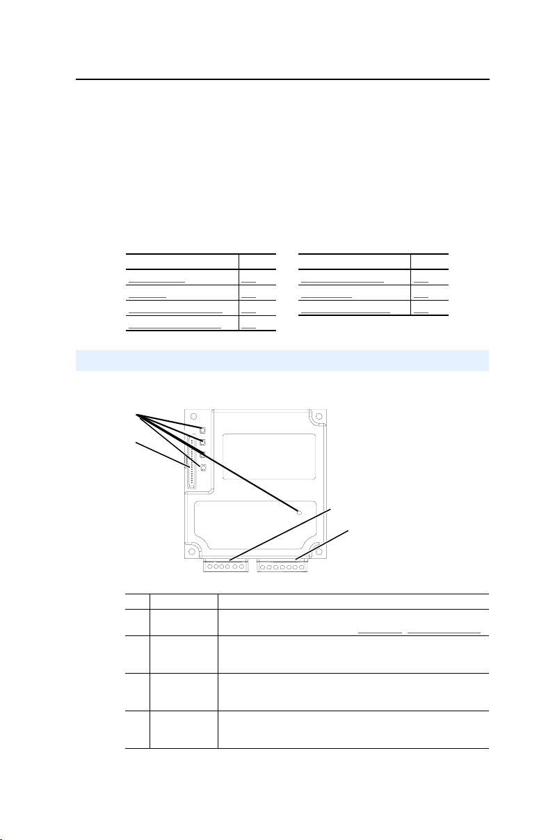
Figure 1.1 Components of the Adapter
➊
➋
1-1 Safety Precautions 1-4
1
# Part Description
➊ Status
Indicators
➋ DPI
Connector
➌ Bus In
Interbus
Connector
➍ Bus Out
Interbus
Connector
Five LEDs that indicate the status of the connected drive,
adapter, and network. Refer to Chapter
A 20-pin, single-row shrouded male header. An Internal
Interface cable is connected to this connector and a
connector on the drive.
One 6-pin plug-in connector.
One 7-pin plug-in connector.
➌
➍
7, Troubleshooting.
Page 10

1-2
Getting Started
Features
The Interbus adapter features the following:
• The adapter is mounted in the PowerFlex drive and receives the
required power from the drive. Captive screws are used to secure the
adapter to the drive.
• A number of configuration tools can be used to configure the adapter
and connected drive. The tools include the PowerFlex HIM on the
drive, or drive-configuration software such as DriveExplorer
(version 2.01 or higher) or DriveExecutive (version 1.01 or higher).
• Status indicators report the status of the drive, adapter, and network.
• I/O, including Logic Command/Reference and Datalinks, may be
configured for your application using a parameter.
• Explicit messages are supported (PCP Read/Write).
• User-defined fault actions determine how the adapter and PowerFlex
drive respond to communication disruptions on the network.
Compatible Products
The Interbus adapter is compatible with Allen-Bradley PowerFlex drives
and other products that support DPI. DPI is a second generation
peripheral communication interface. It is a functional enhancement to
SCANport. At the time of publication, compatible products include:
• PowerFlex 70 drives
• PowerFlex 700 drives
• PowerFlex 7000 drives
Page 11

Getting Started
Required Equipment
Equipment Shipped with the Adapter
When you unpack the adapter, verify that the package includes:
❑ One Interbus adapter
❑ A 2.54 cm (1 in.) and a 15.24 cm (6 in.) Internal Interface cable
(only one cable is needed to connect the adapter to the drive)
❑ One grounding wrist strap
❑ LED labels
❑ This manual
User-Supplied Equipment
1-3
To install and configure the Interbus adapter, you must supply:
❑ A small flathead screwdriver
❑ Interbus cable
❑ Configuration tool, such as:
–PowerFlex HIM
– DriveExplorer (version 2.01 or higher)
- with 1203-SSS Serial Converter (version 3.001 or higher)
– DriveExecutive (version 1.01 or higher)
- with 1203-SSS Serial Converter (version 3.001 or higher)
❑ Configuration tool, such as:
– Interbus configuration software (CMD)
Page 12

1-4
Getting Started
Safety Precautions
Please read the following safety precautions carefully.
ATTENTION:
personnel familiar with drive and power products and the associated
!
machinery should plan or implement the installation, start-up,
configuration, and subsequent maintenance of the product using a
Interbus adapter. Failure to comply may result in injury and/or
equipment damage.
ATTENTION:
may contain high voltages that can cause injury or death. Remove all
!
power from the PowerFlex drive, and then verify power has been
removed before installing or removing a Interbus adapter.
ATTENTION:
contains ESD (Electrostatic Discharge) sensitive parts that can be
!
damaged if you do not follow ESD control procedures. Static control
precautions are required when handling the adapter. If you are
unfamiliar with static control procedures, refer to Guarding Against
Electrostatic Damage, Publication 8000-4.5.2.
ATTENTION:
Interbus adapter is transmitting control I/O to the drive, the drive may
!
fault when you reset the adapter. Determine how your drive will
respond before resetting an adapter.
ATTENTION:
Parameters 6 - [Comm Flt Action]
!
the adapter and connected PowerFlex drive if communications are
disrupted. By default, this parameter faults the PowerFlex drive. You
can set this parameter so that the PowerFlex drive continues to run.
Precautions should be taken to ensure that the setting of this parameter
does not create a hazard of injury or equipment damage.
ATTENTION:
system is configured for the first time, there may be unintended or
!
incorrect machine motion. Disconnect the motor from the machine or
process during initial system testing.
Risk of injury or equipment damage exists. Only
Risk of injury or death exists. The PowerFlex drive
Risk of equipment damage exists. The Interbus adapter
Risk of injury or equipment damage exists. If the
Risk of injury or equipment damage exists.
lets you determine the action of
Risk of injury or equipment damage exists. When a
Page 13

Getting Started
1-5
Quick Start
This section is designed to help experienced users start using the
Interbus adapter. If you are unsure about how to complete a step, refer to
the referenced chapter.
Step Refer to
1 Review the safety precautions for the adapter. Throughout This
2 Verify that the PowerFlex drive is properly
installed.
3 Install the adapter.
Verify that the PowerFlex drive is not powered. Then,
connect the adapter to the network using an Interbus
cable and to the drive using the Internal Interface
cable. Use the captive screws to secure and ground the
adapter to the drive.
4 Apply power to the adapter.
The adapter receives power from the drive. Apply
power to the drive. If there is a problem, refer to
7, Troubleshooting.
Chapter
5 Configure the adapter for your application.
Set the parameters for the following features as
required by your application:
• I/O configuration.
• Fault actions.
6 Apply power to the Interbus master and other
devices on the network.
Verify that the master and network are installed and
functioning in accordance with Interbus standards,
and then apply power to them.
7 Configure the scanner to communicate with the
adapter.
Use a network tool for Interbus to configure the
master on the network.
8 Create a ladder logic program.
Use a programming tool to create a ladder logic
program that enables you to do the following:
• Control the adapter and connected drive.
• Monitor or configure the drive using Explicit
Messages.
Manual
Drive User
Manual
2,
Chapter
Installing the
Adapter
Chapter
2,
Installing the
Adapter
3,
Chapter
Configuring the
Adapter
4,
Chapter
Configuring the
Interbus Scanner
5, Using
Chapter
I/O Messaging
Chapter 6, Using
Explicit
Messaging (PCP
Communications)
Page 14
1-6
PWR
STS
CC
RD
TR
BA
Getting Started
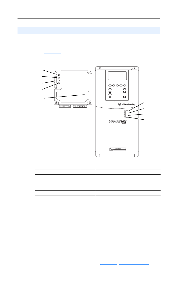
Modes of Operation
The adapter uses five status indicators to report its operating status.
They can be viewed on the adapter or through the drive cover.
(See Figure 1.2
Figure 1.2 Status Indicators
.)
➊
➋
➌
➍
➎
➊
➋
➌
➍
# Status
Indicator
➊ CC Cable Check Green Cable connections good.
➋ RD Remote Bus Disable Off Outgoing remote bus is not switched off.
➌ TR Transmit/Receive Off No PCP connections are carried out
➍ BA Bus Active Green Bus is active.
➎ UL Bus Voltage Green Bus Voltage is OK.
(1)
If all status indicators are off, the adapter is not receiving power. Refer to
Chapter
2, Installing the Adapter, for instructions on installing the adapter.
Note:
The UL indicator is not viewable when the drive cover is installed
or closed.
Note:
Interbus compliance requires different LED functions than what is
normally displayed on the front of the drive (Port, Mod, Net A, and Net
B Led’s). LED labels are provided with the adapter for application to the
drive cover.
Normal
Status
Green PCP connection are being carried out.
Description
(1)
If any other conditions occur, refer to Chapter 7
, Troubleshooting .
Page 15

Getting Started
1-7
Page 16

1-8
Getting Started
Page 17

Chapter
2
Installing the Adapter
Chapter 2 provides instructions for installing the adapter on a PowerFlex
drive.
Topic Page
Preparing for an Installation
Connecting the Adapter to the Network 2-2
Connecting the Adapter to the Drive 2-4
Applying Power 2-6
Preparing for an Installation
Before installing the Interbus adapter:
2-1
• Verify that you have all required equipment. Refer to Chapter 1
Getting Started.
ATTENTION: Risk of equipment damage exists. The Interbus adapter
contains ESD (Electrostatic Discharge) sensitive parts that can be
!
damaged if you do not follow ESD control procedures. Static control
precautions are required when handling the adapter. If you are
unfamiliar with static control procedures, refer to Guarding Against
Electrostatic Damage, Publication 8000-4.5.2.
,
Page 18

2-2 Installing the Adapter
Connecting the Adapter to the Network
ATTENTION: Risk of injury or death exists. The PowerFlex drive
may contain high voltages that can cause injury or death. Remove
!
power from the drive, and then verify power has been discharged before
installing or removing an adapter.
1. Remove power from the drive.
2. Use static control precautions.
3. Route the Interbus cables through the bottom of the PowerFlex drive.
(See Figure 2.3
.)
4. Connect the Interbus connectors to the cables. (See Figure 2.1
Bus In Connector (from previous node on the network).
Terminal Name Description
1 /DO1 Receive
2DO1Receive
3 /DI1 Transmit
4 DI1 Transmit
5 GND Ground Connection
6PE Protective Earth
Bus Out Connector (to next node on the network).
Terminal Name Description
1 /DO2 Receive
2DO2Receive
3 /DI2 Transmit
4 DI2 Transmit
5GND
6RBST
7PE Protective Earth
Important:
1
Ground Connection
1
Te r m i n a t i o n
(1)
Connect GND to RBST if the adapter is NOT the last
adapter on the bus. If the connection is not made, the
adapter will terminate the outgoing bus.
.)
See Figure 2.1
for an explanation of wiring an Interbus network.
Page 19
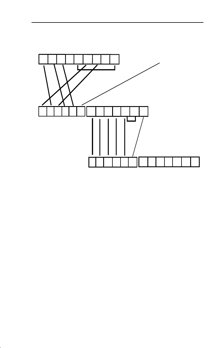
Figure 2.1 Example Network Wiring
SST SLC Scanner
DO DI COM /DO /DI
1 2 3 4 5 6 7 8 9
9-pin D-shell
jumper
Installing the Adapter 2-3
Shield
Station 1
1 2 3 4 5 6
/DO1 DO1 /DI1 DI1 GND PE
Bus In
5. Connect the Interbus connector to the adapter.
Station 2
/DO2 DO2 /DI2 DI2 GND RBST PE
1 2 3 4 5 6 7
Bus Out
jumper
/DO2 DO2 /DI2 DI2 GND RBST PE
1 2 3 4 5 6 1 2 3 4 5 6 7
/DO1 DO1 /DI1 DI1 GND PE
Bus In
Bus Out
Page 20
2-4 Installing the Adapter
Connecting the Adapter to the Drive
1. Remove power from the drive.
2. Use static control precautions.
3. Connect the Internal Interface cable to the DPI port on the drive and
then to DPI connector on the adapter.
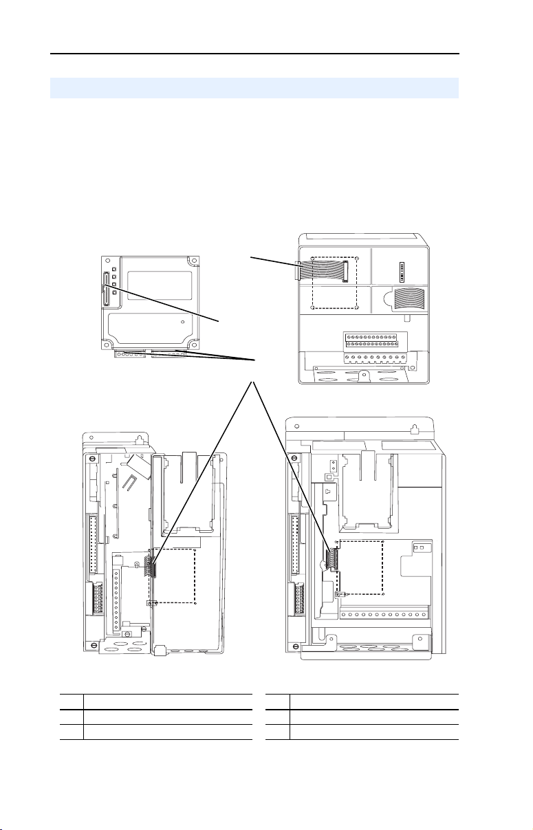
Figure 2.2 DPI Ports and Internal Interface Cables
Interbus Adapter
➋
➊
➌
➍
PowerFlex 70 Drive
PowerFlex 700 Drive
0 - 1 Frame
# Description # Description
➊
15.24 cm (6 in.) Internal Interface cable
➋
DPI Connector
PowerFlex 700 Drive
2 Frame & Larger
➌
Interbus connectors
➍
2.54 cm (1 in.) Internal Interface cable
Page 21
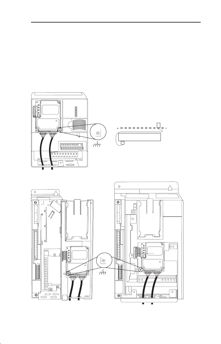
4. Fold the Internal Interface cable behind the adapter and mount the
adapter on the drive using the four captive screws to secure and
ground it to the drive.
Important: On a PowerFlex 70 drive, tighten the screw in the lower
Figure 2.3 Mounting the Adapter
PowerFlex 70 Drive
Adapter mounts in drive.
Installing the Adapter 2-5
right hole to ground the adapter.
On a PowerFlex 700 drive, tighten the screw in the lower
left hole to ground the adapter.
Drive
Adapter
Internal Interface cable folded
behind the adapter and in front of drive.
PowerFlex 700 Drive (0 - 1 Frames)
Adapter mounts on door.
PowerFlex 700 Drive (2 Frame & Larger)
Adapter mounts in drive.
Page 22

2-6 Installing the Adapter
Applying Power
ATTENTION: Risk of equipment damage, injury, or death exists.
Unpredictable operation may occur if you fail to verify that parameter
!
settings and switch settings are compatible with your application.
Verify that settings are compatible with your application before
applying power to the drive.
1. Close the door or reinstall the cover on the drive. Key status
indicators can be viewed on the front of the drive after power has
been applied.
Note: Interbus compliance requires different LED functions than what is
normally displayed on the front of the drive (Port, Mod, Net A, and Net
B Leds). LED labels are provided with the adapter for application to the
drive cover.
2. Apply power to the PowerFlex drive. The adapter receives its power
from the connected drive. When you apply power to the product for
the first time, the status indicators should be green or off after
initialization. Refer to Chapter
information.
7, Troubleshooting for more
3. Apply power to the master device and other devices on the network.
Page 23

Chapter
3
Configuring the Adapter
Chapter 3 provides instructions and information for setting the
parameters in the adapter.
Topic Page Topic Page
Configuration Tools
Using the PowerFlex HIM 3-2 Resetting the Adapter 3-7
Setting the I/O Configuration 3-3
For a list of parameters, refer to Adapter Parameters. For definitions of
terms in this chapter, refer to the Glossary.
Configuration Tools
The Interbus adapter stores parameters and other information in its own
non-volatile memory. You must, therefore, access the adapter to view
and edit its parameters. The following tools can be used to access the
adapter parameters:
3-1 Setting a Fault Action 3-6
Tool Refer To:
DriveExplorer Software (version 2.01
or higher)
Drive Tools 2000 Software (version
1.01 or higher)
PowerFlex HIM page 3-2
DriveExplorer Getting Results Manual
Publication 9306-GR001B-EN-E, or the online
help
DriveExecutive Online Help
,
Page 24
3-2 Configuring the Adapter
Using the PowerFlex HIM
If your drive has either an LED or LCD HIM (Human Interface Module),
access parameters in the adapter as follows:
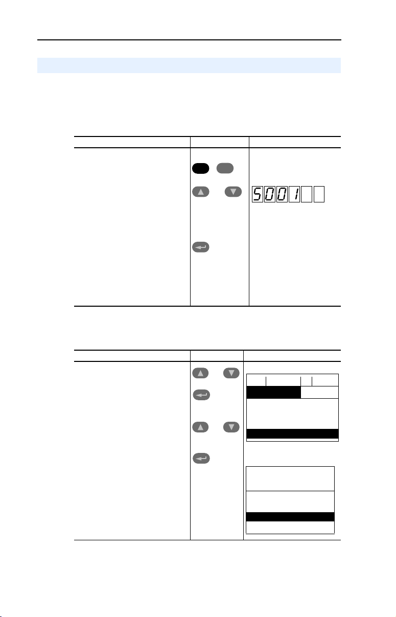
Using an LED HIM
Step Key(s) Example Screens
1. Press the ALT and then Sel
(Device) to display the Device
Screen.
2. Press the Up Arrow or Down
Arrow to scroll to the Interbus
adapter. Letters represent files in
the drive, and numbers represent
ports. The adapter is usually
connected to port 5.
3. Press the Enter key to enter your
selection. A parameter database
is constructed, and then the first
parameter is displayed.
4. Edit the parameters using the
same techniques that you use to
edit drive parameters.
ALT
Device
Sel
OR
Using an LCD HIM
Step Key(s) Example Screens
1. In the main menu, press the Up
Arrow or Down Arrow to scroll to
Device Select.
2. Press Enter to enter your
selection.
3. Press the Up Arrow or Down
Arrow to scroll to the Interbus
(20-COMM-I) adapter.
4. Press Enter to select the
Interbus adapter. A parameter
database is constructed, and
then the main menu for the
adapter is displayed.
5. Edit the parameters using the
same techniques that you use to
edit drive parameters.
OR
OR
F-> Stopped Auto
0.00 Hz
Main Menu:
Diagnostics
Para met er
Device Select
Port 5 Device
20-COMM-I
Main Menu:
Diagnostics
Parame ter
Device Select
Page 25

Configuring the Adapter 3-3
Setting the I/O Configuration
The I/O configuration determines the data that is sent to and from the
drive. This is a two part process: enabling/disabling the data transmitted
between the adapter and drive, and identifying the data transmitted
between the adapter and the scanner.
1. Enable or disable the data transmitted between the adapter and drive.
A “1” enables the I/O
A “0” disables the I/O
Set the bits in Parameter 8 - [DPI I/O Config]:
Figure 3.1 I/O Configuration Screen on an LCD HIM
Port 5 Device
20-COMM-I
Parameter #: 8
DPI I/O Config
xxxxxxxxxxx0000
Cmd/Ref b00
1
Bit Description
0 Logic Command/Reference (Default)
1 Datalink A
2 Datalink B
3 Datalink C
4 Datalink D
5 - 16 Not Used
Bit 0 is the right-most bit. In Figure 3.1, it is highlighted and equals
“1.”
2. If Logic Command/Reference is enabled, configure the parameters in
the drive to accept the logic and Reference from the adapter. For
example, set Parameter 90 - [Speed Ref A Sel] in a PowerFlex 70
or 700 drive to “DPI Port 5” so that the drive uses the Reference from
the adapter. Also, verify that the mask parameters (for example,
Parameter 276 - [Logic Mask]) in the drive are configured to
receive the desired logic from the adapter.
3. If you enabled one or more Datalinks, configure parameters in the
drive to determine the source and destination of data in the
Datalink(s). Also, ensure that the Interbus adapter is the only adapter
using the enabled Datalink(s).
Page 26

3-4 Configuring the Adapter
4. Interbus requires the network I/O mapping to be configured first in
the adapter. CMD software will read this configuration online when
it is configuring the scanner.
Process Input Data Description (PIDD) words map input data on the
network (data seen as inputs to the scanner and controller program).
Example input data includes Logic Status, Feedback and Datalinks
(Datalink x1 Out). Up to 9 words of input data can be mapped.
Process Output Data Description (PODD) words map output data on
the network (data sent as outputs from the scanner and controller
program). Example output data includes Logic Command, Reference
and Datalinks (Datalink x1 In). Up to 9 words of output data can be
mapped.
The following indexes are used to select the I/O data:
Table 3.1 PIDD/PODD Indexes
Input
Val ue
Val ue
(Dec)
Selects
(Hex)
2F9A 12186 Logic Status
2F9B 12187 Feedback
2FA4 12196 Datalink A1 Out
2FA5 12197 Datalink A2 Out
2FA6 12198 Datalink B1 Out
2FA7 12199 Datalink B2 Out
2FA8 12200 Datalink C1 Out
2FA9 12201 Datalink C2 Out
2FAA 12202 Datalink D1 Out
2FAB 12203 Datalink D2 Out
Output
Val ue
Val ue
(Dec)
Selects
(Hex)
2F98 12184 Logic Command
2F99 12185 Reference
2F9C 12188 Datalink A1 In
2F9D 12189 Datalink A2 In
2F9E 12190 Datalink B1 In
2F9F 12191 Datalink B2 In
2FA0 12192 Datalink C1 In
2FA1 12193 Datalink C2 In
2FA2 12194 Datalink D1 In
2FA3 12195 Datalink D2 In
Page 27

Configuring the Adapter 3-5
To configure the adapter for Logic Command/Status, Reference/
Feedback and the maximum number of Datalinks enabled:
Parameter # Name Value
(Hex)
20 PIDD W0 Cfg 2F9A 12186 Logic Status (default)
22 PIDD W1 Cfg 2F9B 12187 Feedback (default)
24 PIDD W2 Cfg 2FA4 12196 Datalink A1 Out
26 PIDD W3 Cfg 2FA5 12197 Datalink A2 Out
Input 28 PIDD W4 Cfg 2FA6 12198 Datalink B1 Out
30 PIDD W5 Cfg 2FA7 12199 Datalink B2 Out
32 PIDD W6 Cfg 2FA8 12200 Datalink C1 Out
34 PIDD W7 Cfg 2FA9 12201 Datalink C2 Out
36 PIDD W8 Cfg 2FAA 12202 Datalink D1 Out
38 PODD W0 Cfg 2F98 12184 Logic Command (default)
40 PODD W1 Cfg 2F99 12185 Reference (default)
42 PODD W2 Cfg 2F9C 12188 Datalink A1 In
44 PODD W3 Cfg 2F9D 12189 Datalink A2 In
Output 46 PODD W4 Cfg 2F9E 12190 Datalink B1 In
48 PODD W5 Cfg 2F9F 12191 Datalink B2 In
50 PODD W6 Cfg 2FA0 12192 Datalink C1 In
52 PODD W7 Cfg 2FA1 12193 Datalink C2 In
54 PODD W8 Cfg 2FA2 12194 Datalink D1 In
Value
(Dec)
Description
Note that Datalink D2 is not used in this example because maximum
configuration has been reached. The maximum configuration is shown to
illustrate utilizing all 9 words of inputs and 9 words of outputs.
Depending on your application needs, any subset of the above example
can be implemented.
The corresponding Parameter 8 - [DPI I/O Config] setting would be
“11111” for all of the above information to transfer between the adapter
and the drive.
5. Reset the adapter. Refer to the Resetting the Adapter
section in this
chapter.
The adapter is ready to receive I/O from the master (i.e., scanner). You
must now configure the scanner to recognize and transmit I/O to the
adapter. Refer to Chapter
4, Configuring the Interbus Scanner.
Page 28

3-6 Configuring the Adapter
Setting a Fault Action
By default, when communications are disrupted (for example, a cable is
disconnected) the drive responds by faulting if it is using I/O from the
network. You can configure a different response to communication
disruptions using Parameter 6 - [Comm Flt Action].
ATTENTION:
Parameters 6 - [Comm Flt Action]
!
the adapter and connected PowerFlex drive if communications are
Risk of injury or equipment damage exists.
lets you determine the action of
disrupted. By default, this parameter faults the PowerFlex drive. You
can set this parameter so that the PowerFlex drive continues to run.
Precautions should be taken to ensure that the setting of this parameter
does not create a hazard of injury or equipment damage.
To change the fault action
• Set the values of Parameters to the desired responses:
Value Action Description
0 Fault (default) The drive is faulted and stopped. (Default)
1 Stop The drive is stopped, but not faulted.
2 Zero Data The drive is sent 0 for output data after a
3 Hold Last The drive continues in its present state after a
4 Send Flt Cfg The drive is sent the data that you set in the fault
Figure 3.2 Fault Action Screen on an LCD HIM
Port 5 Device
20-COMM-I
Parameter #6:
Comm Flt Action
0
Fault
communications disruption. This does not
command a stop.
communications disruption.
configuration parameters (Parameters 10 - [Flt Cfg
Logic] through 19- [Flt Cfg D2]).
Changes to the parameter take effect immediately. A reset is not
required.
Page 29

Configuring the Adapter 3-7
To set the fault configuration parameters
If you set Parameter 6 - [Comm Flt Action] to the “Send Flt Cfg,” the
values in the following parameters are sent to the drive after a
communications fault occurs. You must set these parameters to values
required by your application.
Number Name Description
10 Flt Cfg Logic A 16-bit value sent to the drive for Logic Command.
11 Flt Cfg Ref A 32-bit value (0 – 4294967295) sent to the drive as a
12 – 19 Flt Cfg x1 In
Reference or Datalink.
Important: If the drive uses a 16-bit Reference or 16-bit
Datalinks, the most significant word of the value must be
set to zero (0) or a fault will occur.
Changes to these parameters take effect immediately. A reset is not
required.
Resetting the Adapter
Changes to switch settings or some adapter parameters require that you
reset the adapter before the new settings take effect. You can reset the
adapter by cycling power to the drive or by using the following
parameter:
ATTENTION: Risk of injury or equipment damage exists. If the
adapter is transmitting control I/O to the drive, the drive may fault when
!
you reset the adapter. Determine how your product will respond before
resetting a connected adapter.
• Set the Parameter 05 - [Reset Module] to Reset Module:
Figure 3.3 Reset Screen on an LCD HIM
Port 5 Device
20-COMM-I
Parameter #: 5
Reset Module
1
Reset Module
Value Description
0 Ready (Default)
1 Reset Module
2 Set Defaults
When you enter 1 = Reset Module, the adapter will be immediately
reset. When you enter 2 = Set Defaults, the adapter will set all adapter
parameters to their factory-default settings. The value of this parameter
will be restored to 0 = Ready after the adapter is reset.
Page 30
3-8 Configuring the Adapter
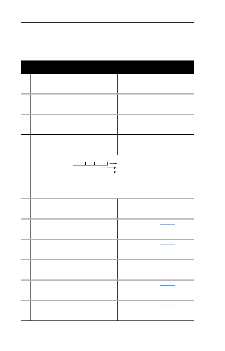
The following parameters provide information about how the adapter is
configured. You can view these parameters at any time.
Parameter
No. Name and Description Details
01 [DPI Port]
Port to which the adapter is connected. This will
usually be port 5.
03 [Ref/Fdbk Size]
Size of the Reference/Feedback. The drive
determines the size of the Reference/Feedback.
04 [Datalink size]
Size of each Datalink word. The drive determines
the size of Datalinks.
09 [DPI I/O Active]
I/O that the adapter is actively transmitting. The
value of this parameter will usually be equal to the
value of Parameter 13 - DPI I/O Config.
Bit
Default
21 PIDD W0 Actual
Actual Process Input Description for Word 0
Displays the Actual PIDD Config being transmitted
to word 0 in the Interbus Master.
23 PIDD W1 Actual
Actual Process Input Description for Word 1
Displays the Actual PIDD Config being transmitted
to word 1 in the Interbus Master.
25 PIDD W2 Actual
Actual Process Input Description for Word 2
Displays the Actual PIDD Config being transmitted
to word 2 in the Interbus Master.
27 PIDD W3 Actual
Actual Process Input Description for Word 3
Displays the Actual PIDD Config being transmitted
to word 3 in the Interbus Master.
29 PIDD W4 Actual
Actual Process Input Description for Word 4
Displays the Actual PIDD Config being transmitted
to word 4 in the Interbus Master.
31 PIDD W5 Actual
Actual Process Input Description for Word 5
Displays the Actual PIDD Config being transmitted
to word 5 in the Interbus Master.
Default: 0
Minimum: 0
Maximum: 7
Type: Read Only
Default: 0 = 16-bit
Values: 0 = 16-bit
Type: Read/Write
Default: 0 = 16-bit
Values: 0 = 16-bit
Type: Read Only
Default: xxx0 0001
Bit Values: 0 = I/O disabled
Type: Read Only
Bit Definitions
01234576
0 = Cmd/Ref
10000xxx
1 = Datalink A
2 = Datalink B
3 = Datalink C
4 = Datalink D
5 = Not Used
6 = Not Used
7 = Not Used
Val ue : S ee Ta bl e B. 1
Type: Read Only
Val ue : S ee Ta bl e B. 1
Type: Read Only
Val ue : S ee Ta bl e B. 1
Type: Read Only
Val ue : S ee Ta bl e B. 1
Type: Read Only
Val ue : S ee Ta bl e B. 1
Type: Read Only
Val ue : S ee Ta bl e B. 1
Type: Read Only
1 = 32-bit
1 = 32-bit
1 = I/O enabled
Page 31

Parameter
No. Name and Description Details
33 PIDD W6 Actual
Actual Process Input Description for Word 6
Displays the Actual PIDD Config being transmitted
to word 6 in the Interbus Master.
35 PIDD W7 Actual
Actual Process Input Description for Word 7
Displays the Actual PIDD Config being transmitted
to word 7 in the Interbus Master.
37 PIDD W8 Actual
Actual Process Input Description for Word 8
Displays the Actual PIDD Config being transmitted
to word 8 in the Interbus Master.
39 PODD W0 Actual
Actual Process Output Description for Word 0
Displays the actual PODD Configuration being
received from word 0 in the Interbus Master.
41 PODD W1 Actual
Actual Process Output Description for Word 1
Displays the actual PODD Configuration being
received from word 1 in the Interbus Master.
43 PODD W2 Actual
Actual Process Output Description for Word 2
Displays the actual PODD Configuration being
received from word 2 in the Interbus Master.
45 PODD W3 Actual
Actual Process Output Description for Word 3
Displays the actual PODD Configuration being
received from word 3 in the Interbus Master.
47 PODD W4 Actual
Actual Process Output Description for Word 4
Displays the actual PODD Configuration being
received from word 4 n the Interbus Master.
49 PODD W5 Actual
Actual Process Output Description for Word 5
Displays the actual PODD Configuration being
received from word 5 in the Interbus Master.
51 PODD W6 Actual
Actual Process Output Description for Word 6
Displays the actual PODD Configuration being
received from word 6 in the Interbus Master.
53 PODD W7 Actual
Actual Process Output Description for Word 7
Displays the actual PODD Configuration being
received from word 7 in the Interbus Master.
55 PODD W8 Actual
Actual Process Output Description for Word 8
Displays the actual PODD Configuration being
received from word 8 in the Interbus Master.
57 PCP Comm Act
Actual PCP configuration
Val ue : S ee Ta bl e B. 1
Type: Read Only
Val ue : S ee Ta bl e B. 1
Type: Read Only
Val ue : S ee Ta bl e B. 1
Type: Read Only
Val ue : S ee Ta bl e B. 1
Type: Read Only
Val ue : S ee Ta bl e B. 1
Type: Read Only
Val ue : S ee Ta bl e B. 1
Type: Read Only
Val ue : S ee Ta bl e B. 1
Type: Read Only
Val ue : S ee Ta bl e B. 1
Type: Read Only
Val ue : S ee Ta bl e B. 1
Type: Read Only
Val ue : S ee Ta bl e B. 1
Type: Read Only
Val ue : S ee Ta bl e B. 1
Type: Read Only
Val ue : S ee Ta bl e B. 1
Type: Read Only
ENUM: Enabled, Disabled
Configuring the Adapter 3-9
Page 32

3-10 Configuring the Adapter
Notes:
Page 33

Chapter
4
Configuring the Interbus Scanner
Interbus scanners are available from several manufacturers, including
SST. Chapter 4 provides instructions on how to utilize Phoenix Contact
CMD software to configure the network on an SST scanner.
To pi c Pa ge
Example Network
Using CMD Software to Configure the Network 4-4
Adapter Configuration Settings to use with Ladder Examples 4-3
PowerFlex 70 Settings to use with Ladder Examples 4-15
RSLogix 500 SST Interbus Scanner Configuration 4-15
Example Network
All examples in this manual are based on the following:
4-1
• SLC controller with a SST Interbus scanner (SST-IBS-SLC)
in slot 1.
• PowerFlex 70 at Device 1.0 / CR 2 (CR# is needed for PCP
commands).
• Power Flex 70 at Device 2.0 / CR 3 (CR# is needed for PCP
commands).
• Logic Command / Status, Reference / Feedback and Datalinks A-D
are enabled in the 20-COMM-I and mapped to network I/O.
• Phoenix Contact CMD software is used to configure the network.
This chapter describes the steps to configure a simple network like what
is featured in Figure 4.1
.
Page 34

4-2 Configuring the Interbus Scanner
Figure 4.1 Example Interbus Network
Interbus
REMOTE OUT
Config
RS232 Port
Fault LED
COMM LED
PowerFlex 70
Station 1.0
(CR=2)
Powe rFlex 70
Station 2.0
(CR=3)
Page 35

Configuring the Interbus Scanner 4-3
Adapter Configuration Settings to use with Ladder Examples
Prior to setting up the SST Interbus scanner with CMD software, the
following parameters need to be configured to use the example ladder
logic program:
20-COMM-I
Parameter Name Value Description
Binary/
Decimal
8 DPI I/O Config xxx1 1111 001F Enable Cmd/Ref,
20 PIDD W0 Cfg 12186 2F9A Logic Status
22 PIDD W1 Cfg 12187 2F9B Feedback
24 PIDD W2 Cfg 12196 2FA4 Datalink A1 Out
26 PIDD W3 Cfg 12197 2FA5 Datalink A2 Out
28 PIDD W4 Cfg 12198 2FA6 Datalink B1 Out
30 PIDD W5 Cfg 12199 2FA7 Datalink B2 Out
32 PIDD W6 Cfg 12200 2FA8 Datalink C1 Out
34 PIDD W7 Cfg 12201 2FA9 Datalink C2 Out
36 PIDD W8 Cfg 12202 2FAA Datalink D1 Out
38 PODD W0 Cfg 12184 2F98 Logic Command
40 PODD W1 Cfg 12185 2F99 Reference
42 PODD W2 Cfg 12188 2F9C Datalink A1 In
44 PODD W3 Cfg 12189 2F9D Datalink A2 In
46 PODD W4 Cfg 12190 2F9E Datalink B1 In
48 PODD W5 Cfg 12191 2F9F Datalink B2 In
50 PODD W6 Cfg 12192 2FA0 Datalink C1 In
52 PODD W7 Cfg 12193 2FA1 Datalink C2 In
54 PODD W8 Cfg 12194 2FA2 Datalink D1 In
Hexadecimal
Datalinks A-D
PIDD and PODD parameters are used to identify what will be
transmitted on the network and the amount of network I/O the CMD
software will allocate on the scanner.
Page 36

4-4 Configuring the Interbus Scanner
Using CMD Software to Configure the Network
Before starting the configuration, make sure the PC running CMD
software is connected to the SST scanner (a null modem cable is
supplied with the scanner). The SLC and drives need to be connected to
the Interbus network and powered in order for CMD to configure the
network. If it does not already exist, CMD software tool automatically
creates an Allen-Bradley sub-folder (in the Slaves folder).
CMD needs to be in Extended Mode to configure the network. A
password (supplied by Phoenix Contact along with the CMD software),
is requested for this functionality each time CMD is started. After CMD
has started, you can also click O
enter the password.
ptions/Extended (Function Scope) to
1. Select F
Figure 4.2 Creating a new Interbus project
2. Right-click on the Project icon and select Description. Enter a
ile / New from the pull-down menu to create a new project.
(See Figure 4.2.)
name for the project and any additional information desired, as
shown in Figure 4.3
. Click OK when complete.
Page 37

Configuring the Interbus Scanner 4-5
Figure 4.3 Entering a name for the new Interbus project
3. Right-click on the PLC/PC icon and select Description. Enter
a name for the controller and any additional information desired, as
shown in Figure 4.4
Figure 4.4 Entering a name for the Interbus controller
. Click OK when complete.
4. Right-click on the Program icon and select Description. Enter
a name for the program (using the actual RSLogix500 file name is
recommended), and any additional information desired, as shown in
Figure 4.5
Figure 4.5 Entering a name for the Interbus program.
. Click OK when complete.
Page 38

4-6 Configuring the Interbus Scanner
5. When complete, the representation area will look as shown in
Figure 4.6
Figure 4.6 Example Interbus CMD Project
.
This provides useful information regarding the CMD project being
created:
• “PowerFlex 70 Interbus Demo” indicates what this project is for.
• “SLC 5/05” indicates the controller used.
• “Interbus_SLC_Demo” indicates that Interbus_SLC_Demo.RSS
is the associated RSLogix500 program used with this system.
6. To configure the PC Com Port that CMD will use to communicate
with the SST scanner, click on Options/Settings and then the Driver
tab.
7. Click on the Communication Path icon and then the Standard tab.
8. Select the type of port of communication path used. Typically, this is
“Serial Port” and “Com1” respectively, as shown in Figure 4.7
. Click
OK until you return to the main screen.
Figure 4.7 Selecting the Port Communication path.
Page 39

Configuring the Interbus Scanner 4-7
9. Right-click on the Controller Board icon and select Type. Set
the type to “IBS USC/4(4K)” and click OK. This identifies the type
of Interbus controller used on the SST scanner. (See Figure 4.8
Figure 4.8 Selecting the Interbus Controller type
.)
10. Right-click on the Controller Board icon and select Description.
Enter “SST-IBS-SLC” in the name field, as shown in Figure 4.9
Figure 4.9 Entering a Description for the Controller Board
.
Page 40

4-8 Configuring the Interbus Scanner
11. When complete, the representation area will look as shown in Figure
4.10.
Figure 4.10 Example Interbus CMD Project
12. From the pull-down menu select C
onfiguration/Configuration
Frame/Read In and answer Yes to changing the operating state to
Configuration Online. If there are additional prompts, answer OK or
Yes to perform the read anyway. CMD will then read the bus
configuration. (See Figure 4.11
Figure 4.11 CMD Bus Configuration
.)
Page 41

Configuring the Interbus Scanner 4-9
The gray PCP icons represent each PowerFlex 70 drive. The first
PowerFlex 70 has a Device Number of 1.0 and the second has a Device
Number of 2.0.
13. Right-click on the SST-IBS-SLC scanner and select Process Data.
This shows the Interbus I/O mapping for each device on the network,
as shown in Figure 4.12
Figure 4.12 Example Interbus I/O Mapping
.
In the example, the length is 144 bits (9 words) because the 20-COMM-I
was previously configured for the maximum I/O configuration (See
Chapter 3, Setting the I/O Configuration on page 3-3. Depending on
your application needs, this length may be less.
Page 42

4-10 Configuring the Interbus Scanner
The scanner mapping correlates to SLC addressing as follows:
Scanner Scanner
(USC/4) Output SLC (USC/4) Input SLC
0
1
63
64
65
511
The mapping in the scanner is set up in bytes. Inputs to the scanner start
at byte #512 and outputs start at byte #0.
PIDD/PODD parameter settings in the adapter determine the length of
I/O data mapped. In the example, each device is configured for 9 words
(144 bits) of inputs and 9 words (144 bits) of outputs, the maximum
allowed for each device.
O:x.0(high)
O:x.0(low)
O:x.31(low)
M0:x.0(high)
M0:x.0(low)
M0:x.223(low)
512
513
575
576
1023
I:x.0(high)
I:x.0(low)
I:x.31(low)
M1:x.0(high)
M1:x.0(low)
M1:x.223(low)
Page 43

Configuring the Interbus Scanner 4-11
Using the PIDD/PODD values previously set in the 20-COMM-I, the I/O
layout in the scanner is as follows:
Word Inputs
(Data to Master)
0 Logic Status 512 530 Logic Command 0 18
1 Feedback 514 532 Reference 2 20
2 Datalink A1 Out 516 534 Datalink A1 In 4 22
3 Datalink A2 Out 518 536 Datalink A2 In 6 24
4 Datalink B1 Out 520 538 Datalink B1 In 8 26
5 Datalink B2 Out 522 540 Datalink B2 In 10 28
6 Datalink C1 Out 524 542 Datalink C1 In 12 30
7 Datalink C2 Out 526 544 Datalink C2 In 14 32
8 Datalink D1 Out 528 546 Datalink D1 In 16 34
Device 1.0’s SLC addressing is as follows:
Word Inputs
(Data to Master)
0 Logic Status 512 I:1.0 Logic Command 0 O:1.0
1 Feedback 514 I:1.1 Reference 2 O:1.1
2 Datalink A1 Out 516 I:1.2 Datalink A1 In 4 O:1.2
3 Datalink A2 Out 518 I:1.3 Datalink A2 In 6 O:1.3
4 Datalink B1 Out 520 I:1.4 Datalink B1 In 8 O:1.4
5 Datalink B2 Out 522 I:1.5 Datalink B2 In 10 O:1.5
6 Datalink C1 Out 524 I:1.6 Datalink C1 In 12 O:1.6
7 Datalink C2 Out 526 I:1.7 Datalink C2 In 14 O:1.7
8 Datalink D1 Out 528 I:1.8 Datalink D1 In 16 O:1.8
Station Outputs
1.0 2.0 1.0 2.0
(Data from Master)
Station
Assignment Outputs
Scanner SLC Scanner SLC
(Data from Master)
Assignment
Device 2.0’s SLC addressing starts immediately after 1.0 addressing
(I:1.9 and O:1.9).
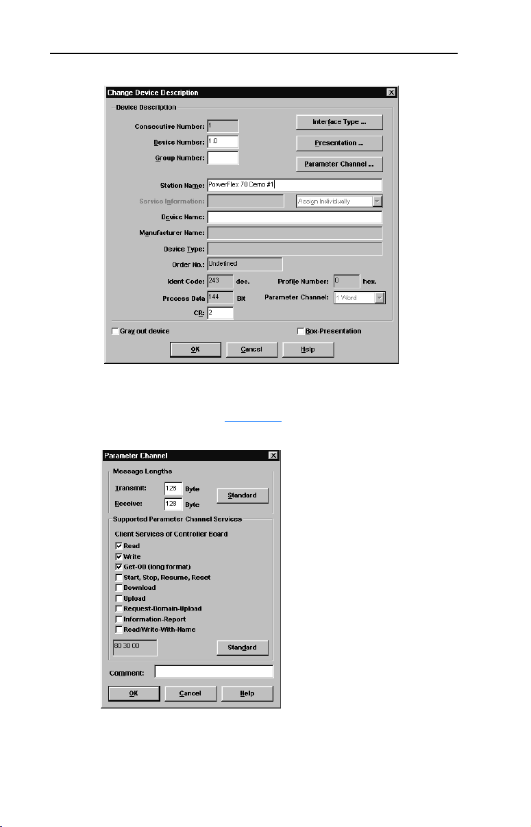
14. Right-click on the 1.0 PCP icon and select D
escription. Enter a
Station Name such as “PowerFlex 70 Demo #1”. Note the
Communication Reference (CR) is 2. The CR needs to be known
when using PCP communication services (explicit messaging). (See
Figure 4.13.)
Page 44
4-12 Configuring the Interbus Scanner
Figure 4.13 Entering a Station Name
15. Click on the Parameter Channel button. Set the Transmit and Receive
to 128 bytes and enable Read, Write, and Get-0D (long format)
services, as shown in Figure 4.14
. Click OK when complete.
Figure 4.14 Selecting data for the Parameter Channel screen
Page 45

Configuring the Interbus Scanner 4-13
16. Repeat steps #14 and #15 using the 2.0 PCP icon . Enter a
Station name such as “PowerFlex 70 Demo #2”. Note the
Communication Reference (CR) is 3. The CR needs to be known
when using PCP communication services (explicit messaging). Click
OK when complete.
17. When complete, the representation area will look as shown in Figure
4.15.
Figure 4.15 Example PowerFlex 70 Demo #2
18. Right-click on the SST-IBS-SLC icon and select P
arameterization/
Execute. Select “Startup without PDP” as shown in Figure 4.16 and
click OK. This uses the mapping already set up in the scanner and
does not allow re-mapping by the software tool.
Page 46

4-14 Configuring the Interbus Scanner
Figure 4.16 Selecting data for Parameterization/Execute screen
If parameterization execution is successful, there will be a prompt to
click OK. Click OK.
19. When complete, the representation area will look as shown in Figure
4.17.
Figure 4.17 Example Parameterization Execution
20. Click F
ile/Save from the pull-down menu and save the project.
Page 47

Configuring the Interbus Scanner 4-15
PowerFlex 70 Settings to use with Ladder Examples
The following parameters should be configured to use the example
ladder logic program.
PowerFlex 70
Parameter Name Value Description
90 Speed Ref A Sel 22 DPI Port 5 (20-COMM-I) provides the
300 Data In A1 140 Pr. 140 [Accel Time 1]
301 Data In A2 142 Pr. 142 [Decel Time 1]
302 Data In B1 100 Pr. 100 [Jog Speed]
303 Data In B2 155 Pr. 155 [Stop Mode A]
304 Data In C1 101 Pr. 101 [Preset Speed 1]
305 Data In C2 102 Pr. 102 [Preset Speed 2]
306 Data In D1 103 Pr. 103 [Preset Speed 3]
310 Data Out A1 140 Pr. 140 [Accel Time 1]
311 Data Out A2 142 Pr. 142 [Decel Time]
312 Data Out B1 100 Pr. 100 [Jog Speed]
313 Data Out B2 155 Pr. 155 [Stop Mode A]
314 Data Out C1 101 Pr. 101 [Preset Speed 1]
315 Data Out C2 102 Pr. 102 [Preset Speed 2]
316 Data Out D1 103 Pr. 103 [Preset Speed 3]
Reference
RSLogix 500 SST Interbus Scanner Configuration
The SST Interbus scanner is configured by clicking on the I/O
Configuration in RSLogix500. The SST-IBS-SLC has an ID Code of
13635. The following settings are used by the example ladder logic
program, as shown in Figure 4.18
and Figure 4.19.
Page 48

4-16 Configuring the Interbus Scanner
Figure 4.18 Scanner I/O Configuration
Figure 4.19 Scanner_G_ files
G File Data Information:
Word Value
(Decimal)
0 8224 2020 Fixed to 2020h by the SLC
1 4096 1000 Enables the command interface between the SLC
2 0 0 Use the CMD specified Bus Update Time
3 0 0 Use the CMD specified Bus Warning Time
4 0 0 Use the CMD specified Bus Timeout
5 0 0 The number of words used at the beginning of the
6 128 80 Maximum data size for commands and replies sent
Val ue
(Hexadecimal)
Description
and the USC/4
M files for Inputs and Outputs
between the SLC and the scanner
Refer to the SST-IBS-SLC User’s Guide for more information.
Page 49

Notes:
Configuring the Interbus Scanner 4-17
Page 50

4-18 Configuring the Interbus Scanner
Notes:
Page 51

Chapter
Using I/O Messaging
Chapter 5 provides information and examples that explain how to use
I/O Messaging to control a PowerFlex drive.
Topic Page Topic Page
About I/O Messaging
Understanding the I/O Image 5-2 SLC Ladder Logic Example - Main
Using Logic Command/Status 5-4 SLC Ladder Logic Example - Station
Using Reference/Feedback 5-4 SLC Ladder Logic Example - Station
Using Datalinks 5-4
ATTENTION: Risk of injury or equipment damage exists. The
examples in this publication are intended solely for purposes of
!
example. There are many variables and requirements with any
application. Rockwell Automation does not assume responsibility or
liability (to include intellectual property liability) for actual use of the
examples shown in this publication.
5-1 SLC Example Ladder Logic Program 5-6
Program
1 Program
2 Program
5
5-8
5-9
5-11
About I/O Messaging
On Interbus, I/O messaging is used to transfer the data which controls
the PowerFlex drive and sets its Reference. I/O can also be used to
transfer data to and from Datalinks in PowerFlex drives.
The Interbus adapter provides options for configuring and using I/O,
including the following:
• The size of I/O can be configured by enabling or disabling the Logic
Command/Reference and Datalinks.
Chapter
Interbus Scanner discuss how to configure the adapter and scanner on the
network for these options. The Glossary defines the different options.
This chapter discusses how to use I/O after you have configured the
adapter and scanner.
3, Configuring the Adapter and Chapter 4, Configuring the
Page 52

5-2 Using I/O Messaging
Understanding the I/O Image
The terms input and output are defined from scanner’s point of view.
Therefore, Output I/O is data that is output from the scanner and
consumed by the Interbus adapter. Input I/O is status data that is
produced by the adapter and consumed as input by the scanner. The I/O
image table will vary based on the following:
• Size (either 16-bit or 32-bit) of the Reference/Feedback word and
Datalink words used by the drive.
• Configuration of Parameter 8 - [DPI I/O Config] in the adapter. If
all I/O is not enabled, the image table is truncated. The image table
always uses consecutive words starting at word 0.
Figure 5.1
Figure 5.1 Example I/O Image with All I/O Enabled
Controller
illustrates an example of an I/O image with 16-bit words.
Interbus
Scanner
Output
Image
(Write)
M0/M1
Files
Input
Image
(Read)
Adapter PowerFlex Drive
Word and I/O
0 Logic Command
1 Reference
2 Datalink In A1
3 Datalink In A2
4 Datalink In B1
5 Datalink In B2
6 Datalink In C1
7 Datalink In C2
8 Datalink In D1
PCP Communications
0 Logic Status
1 Feedback
2 Datalink Out A1
3 Datalink Out A2
4 Datalink Out B1
5 Datalink Out B2
6 Datalink Out C1
7 Datalink Out C2
8 Datalink Out D1
DPI
Logic Command
Reference
Data In A1
Data In A2
Data In B1
Data In B2
Data In C1
Data In C2
Data In D1
Message
Handler
Logic Status
Feedback
Data Out A1
Data Out A2
Data Out B1
Data Out B2
Data Out C1
Data Out C2
Data Out D1
M0/M1
Files
PCP Communications
Message
Handler
Page 53

Using I/O Messaging 5-3
An image that uses 32-bit words for Reference and Datalinks would
change the I/O image as follows:
Wor d I/O
0 Logic Command/Status
1 - 2 Reference/Feedback
3 - 6 Datalink A1/A2
7 - 10 Datalink B1/B2
Figure 5.2
illustrates an example of an I/O image that does not use all of
the I/O data. Only the Logic Command/Reference and Datalink B are
enabled. In this example, the Reference is a 32-bit word, and Datalinks
are 16-bit words.
Figure 5.2 Example I/O Image with Only Logic/Reference and Datalink B Enabled
Interbus
Controller Scanner Adapter PowerFlex Drive
Word and I/O
Output
Image
(Write)
Input
Image
(Read)
0 Logic Command
1 Reference (LSW)
2 Reference (MSW)
3 Datalink In B1
4 Datalink In B2
0 Logic Status
1 Feedback (LSW)
2 Feedback (MSW)
3 Datalink Out B1
4 Datalink Out B2
DPI
Logic Command
Reference
Data In A1
Data In A2
Data In B1
Data In B2
Data In C1
Data In C2
Data In D1
Logic Status
Feedback
Data Out A1
Data Out A2
Data Out B1
Data Out B2
Data Out C1
Data Out C2
Data Out D1
LSW = Least Significant Word (Bits 15 - 0)
MSW = Most Significant Word (Bits 31 - 16)
Page 54

5-4 Using I/O Messaging
Using Logic Command/Status
When enabled, the Logic Command/Status word is always word 0 in the
I/O image. The Logic Command is a 16-bit word of control produced by
the scanner and consumed by the adapter. The Logic Status is a 16-bit
word of status produced by the adapter and consumed by the scanner.
This manual contains the bit definitions for compatible products
available at the time of publication in Appendix
Status Words. For other products, refer to their documentation.
Using Reference/Feedback
When enabled, Reference/Feedback always begins at word 1 in the I/O
image. The Reference (16 bits or 32 bits) is produced by the controller
and consumed by the adapter. The Feedback (16 bits or 32 bits) is
produced by the adapter and consumed by the controller. The size of the
Reference/Feedback is determined by the product and displayed in
Parameter 03 - [Ref/Fdbk Size] in the adapter.
Size Valid Values In I/O Image Example
16-bit -32768 to 32767 Word 1 Figure 5.1
32-bit -2147483648 to 2147483647 Word 1 and Word 2 Figure 5.2
C, Logic Command/
Using Datalinks
A Datalink is a mechanism used by PowerFlex drives to transfer data to
and from the controller. Datalinks allow a parameter value to be changed
without using an Explicit Message. When enabled, each Datalink
consumes either two 16-bit or 32-bit words in both the input and output
image depending on its size. The size of Datalinks (16-bit words or
32-bit words) is determined by the drive and displayed in Parameter 04
- [Datalink Size] in the adapter.
Rules for Using Datalinks
• Each set of Datalink parameters in a PowerFlex drive can be used by
only one adapter. If more than one adapter is connected to a single
drive, multiple adapters must not try to use the same Datalink.
• Parameter settings in the drive determine the data passed through the
Datalink mechanism. Refer to the documentation for your product.
• When you use a Datalink to change a value, the value is not written
to the Non-Volatile Storage (NVS). The value is stored in volatile
memory and lost when the drive loses power.
Page 55

Using I/O Messaging 5-5
32-Bit Parameters using 16-Bit Datalinks
To read (and/or write) a 32-bit parameter using 16-bit Datalinks,
typically both Datalinks (x1 and x2) are set to the 32-bit parameter. For
example, to read Parameter 09 - [Elapsed MWh] in a PowerFlex 70,
both Datalink A1 and A2 are set to “9”. Datalink A1 will contain the
least significant word (LSW) and Datalink A2 the most significant word
(MSW). In this example, the parameter 9 value of 5.8MWh is read as a
“58” in Datalink A1.
Datalink Most/Least Significant Word Parameter Data (decimal)
A1 LSW 9 58
A2 MSW 9 0
Regardless of the Datalink combination, x1 will always contain the LSW
and x2 will always contain the MSW. In the following examples
Parameter 242 - [Power Up Marker] contains a value of 88.4541
hours.
Datalink Most/Least Significant Word Parameter Data (decimal)
A1 LSW 242 32573
A2 - Not Used - 0 0
Datalink Most/Least Significant Word Parameter Data (decimal)
A1 - Not Used - 0 0
A2 MSW 242 13
Datalink Most/Least Significant Word Parameter Data (decimal)
A2 MSW 242 13
B1 LSW 242 32573
32-bit data is stored in binary as follows:
MSW 2
LSW 215 through 2
31
through 2
16
0
Example:
Parameter 242 - [Power Up Marker] = 88.4541 hours
MSW = 13
decimal
= 1101
= 219 + 218 + 216 = 851968
binary
LSW = 32573
851968 + 32573 = 884541
Page 56

5-6 Using I/O Messaging
SLC Example Ladder Logic Program
The Interbus example program uses a SLC processor with an SST
Interbus scanner (SST-IBS-SLC) in the first slot of the rack and will
work with PowerFlex 70 or PowerFlex 700 drives.
Function of the Example Program
The program is written for (2) drives on the network and demonstrates
using:
• Logic Command / Reference
• Logic Status / Feedback
• Datalinks
• PCP Read / Write (See Chapter
Adapter Settings
The 20-COMM-I node addresses are set via CMD software to:
• “1.0” (CR=2) for Station 1
• “2.0” (CR=3) for Station 2
6.)
See Chapter
Examples.
PowerFlex 70 Settings
See Chapter 4, PowerFlex 70 Settings to use with Ladder Examples.
SST Scanner Settings
See Chapter
4, Adapter Configuration Settings to use with Ladder
4, RSLogix 500 SST Interbus Scanner Configuration.
Page 57

Using I/O Messaging 5-7
SLC Data Table
Read Data
The scanner is configured for 18 bytes (9 words) of inputs for each drive,
the maximum amount allowed. Two drives require 36 bytes (18 words)
max.
Station 1
Address
I:1.0 I:1.9 Logic Status
I:1.1 I:1.10 Feedback
I:1.2 I:1.11 Datalink A1
I:1.3 I:1.12 Datalink A2
I:1.4 I:1.13 Datalink B1
I:1.5 I:1.14 Datalink B2
I:1.6 I:1.15 Datalink C1
I:1.7 I:1.16 Datalink C2
I:1.8 I:1.17 Datalink D1
Station 2
Address
Function
Write Data
The Scanner is configured for 18 bytes (9 words) of outputs for each
drive, the maximum amount allowed. Two drives require 36 bytes (18
words).
Station 1
Address
O:1.0 O:1.9 Logic Command
O:1.1 O:1.10 Reference
O:1.2 O:1.11 Datalink A1
O:1.3 O:1.12 Datalink A2
O:1.4 O:1.13 Datalink B1
O:1.5 O:1.14 Datalink B2
O:1.6 O:1.15 Datalink C1
O:1.7 O:1.16 Datalink C2
O:1.8 O:1.17 Datalink D1
Station 2
Address
Function
Logic Command/Status Words
These examples use the Logic Command word and Logic Status word
for PowerFlex 70 and PowerFlex 700 drives. Refer to Appendix C,
Logic Command/Status Words to view these. The definition of the bits in
these words may vary if you are using a different DPI product. Refer to
the documentation for your product.
Page 58

5-8 Using I/O Messaging
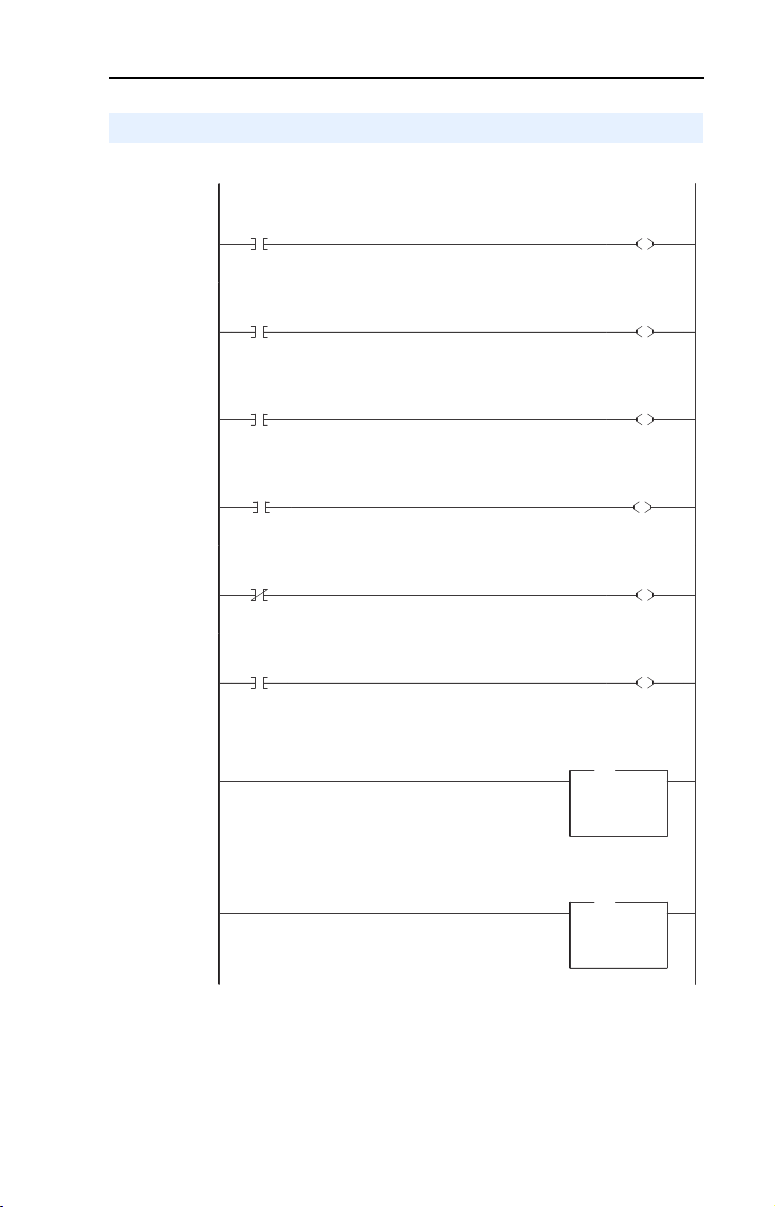
SLC Ladder Logic Example - Main Program
Figure 5.3 Example SLC Ladder Logic - Main Program
The following rung performs power-up initialization of the PCP Read and PCP Write routines.
First Pass
0000
0001
0002
0003
0004
0005
S:1
15
Execute LAD 3 - Station 1.0 Drive Logic (Logic Command / Status, Reference / Feedback and Datalinks).
Execute LAD 4 - Station 2.0 Drive Logic (Logic Command / Status, Reference / Feedback and Datalinks).
Execute LAD 5 - PCP Read Subroutine (Explicit Messaging)
Can Read OR Write at any one time. B3:47/0 will be turned off by the subroutine when the reading is complete and signals that
another read (or write) cycle can take place.
Execute
PCP Read
Subroutine
B3:47
0
Execute LAD 6 - PCP Write Subroutine (Explicit Messaging)
Can only Write OR Read at any one time. B3:47/10 will be turned off by the subroutine when the writing is complete and
signals that another write (or read) cycle can take place.
Execute
PCP Read
Subroutine
B3:47
0
Execute
PCP Write
Subroutine
B3:47
10
Execute
PCP Write
Subroutine
B3:47
10
Execute
PCP Read
Subroutine
B3:47
U
0
PCP Read
Routine
1-shot
B3:47
U
1
PCP Read
Reply Msg
1-Shot
B3:47
U
2
Execute
PCP Write
Subroutine
B3:47
U
10
PCP Write
Routine
1-shot
B3:47
U
11
PCP Write
Reply Msg
1-Shot
B3:47
U
12
JSR
JSR
Jump To Subroutine
SBR File Number U:3
JSR
JSR
Jump To Subroutine
SBR File Number U:4
JSR
JSR
Jump To Subroutine
SBR File Number U:5
JSR
JSR
Jump To Subroutine
SBR File Number U:6
END
Page 59
Using I/O Messaging 5-9
SLC Ladder Logic Example - Station 1 Program
Figure 5.4 Example SLC Ladder Logic - Station 1 Program
Controlling the Logic Command to the drive at Station 1.0.
Station 1.0
Start
Command
0000
0001
0002
0003
0004
0005
0006
0007
B3:20
1
Station 1.0
Stop
Command
B3:20
0
Station 1.0
Jog
Command
B3:20
2
Station 1.0
Clear Faults
Command
B3:20
3
Station 1.0
Reverse
Command
B3:20
4
Station 1.0
Reverse
Command
B3:20
4
Station 1.0 Speed Reference
PowerFlex 70 Speed Ref A Sel (Pr.90) needs to be set to 'DPI Port 5'
Station 1.0 Datalink A1
Datalink A1 (Pr. 300) set to Acceleration Time 1 (Pr. 140)
Station 1.0
Logic Command
START
Station 1.0
Logic Command
STOP
Station 1.0
Logic Command
JOG
Station 1.0
Logic Command
CLEAR FAULTS
Station 1.0
Logic Command
FORWARD
Station 1.0
Logic Command
REVERSE
Station 1.0
Speed Reference
MOV
MOV
Move
Source N19:1
8192<
Dest O:1.1
8192<
Station 1.0
Datalink A1
MOV
MOV
Move
Source N19:2
50<
Dest O:1.2
50<
O:1.0
OTHER
O:1.0
OTHER
O:1.0
OTHER
O:1.0
OTHER
O:1.0
OTHER
O:1.0
OTHER
1
0
2
3
4
5
Page 60

5-10 Using I/O Messaging
Figure 5.4 Example SLC Ladder Logic - Station 1 Program (Continued)
Station 1.0 Datalink A2
Datalink A2 (Pr. 301) set to Deceleration Time 1 (Pr. 142)
0008
Station 1.0 Datalink B1
Datalink B1 (Pr. 302) set to Jog Speed (Pr. 100)
0009
Station 1.0 Datalink B2
Datalink B2 (Pr. 303) set to Stop Mode A (Pr. 155)
0010
Station 1.0 Datalink C1
Datalink C1 (Pr. 304) set to Preset Speed 1 (Pr. 101)
0011
Station 1.0 Datalink C2
Datalink C2 (Pr. 305) set to Preset Speed 2 (Pr. 102)
0012
Station 1.0 Datalink D1
Datalink D1 (Pr. 306) set to Preset Speed 3 (Pr. 103)
0013
0014
Station 1.0
Datalink A2
MOV
MOV
Move
Source N19:3
50<
Dest O:1.3
50<
Station 1.0
Datalink B1
MOV
MOV
Move
Source N19:4
100<
Dest O:1.4
100<
Station 1.0
Datalink B2
MOV
MOV
Move
Source N19:5
1<
Dest O:1.5
1<
Station 1.0
Datalink C1
MOV
MOV
Move
Source N19:6
100<
Dest O:1.6
100<
Station 1.0
Datalink C2
MOV
MOV
Move
Source N19:7
200<
Dest O:1.7
200<
Station 1.0
Datalink D1
MOV
MOV
Move
Source N19:8
300<
Dest O:1.8
300<
END
Page 61

Using I/O Messaging 5-11
SLC Ladder Logic Example - Station 2 Program
Figure 5.5 Example SLC Ladder Logic - Station 2 Program
Controlling the Logic Command to the drive at Station 2.0.
Station 2.0
Start
Command
0000
0001
0002
0003
0004
0005
0006
0007
B3:21
1
Station 2.0
Stop
Command
B3:21
0
Station 2.0
Jog
Command
B3:21
2
Station 2.0
Clear Faults
Command
B3:21
3
Station 2.0
Reverse
Command
B3:21
4
Station 2.0
Reverse
Command
B3:21
4
Station 2.0 Speed Reference
PowerFlex 70 Speed Ref A Sel (Pr.90) needs to be set to 'DPI Port 5'
Station 2.0 Datalink A1
Datalink A1 (Pr. 300) set to Acceleration Time 1 (Pr. 140)
Station 2.0
Logic Command
START
Station 2.0
Logic Command
STOP
Station 2.0
Logic Command
JOG
Station 2.0
Logic Command
CLEAR FAULTS
Station 2.0
Logic Command
FORWARD
Station 2.0
Logic Command
REVERSE
Station 2.0
Speed Reference
MOV
MOV
Move
Source N19:15
8192<
Dest O:1.10
8192<
Station 2.0
Datalink A1
MOV
MOV
Move
Source N19:16
50<
Dest O:1.11
50<
O:1.9
OTHER
O:1.9
OTHER
O:1.9
OTHER
O:1.9
OTHER
O:1.9
OTHER
O:1.9
OTHER
1
0
2
3
4
5
Page 62

5-12 Using I/O Messaging
Figure 5.5 Example SLC Ladder Logic - Station 2 Program (Continued)
Station 2.0 Datalink A2
Datalink A2 (Pr. 301) set to Deceleration Time 1 (Pr. 142)
0008
Station 2.0 Datalink B1
Datalink B1 (Pr. 302) set to Jog Speed (Pr. 100)
0009
Station 2.0 Datalink B2
Datalink B2 (Pr. 303) set to Stop Mode A (Pr. 155)
0010
Station 2.0 Datalink C1
Datalink C1 (Pr. 304) set to Preset Speed 1 (Pr. 101)
0011
Station 2.0 Datalink C2
Datalink C2 (Pr. 305) set to Preset Speed 2 (Pr. 102)
0012
Station 2.0 Datalink D1
Datalink D1 (Pr. 306) set to Preset Speed 3 (Pr. 103)
0013
0014
Station 2.0
Datalink A2
MOV
MOV
Move
Source N19:17
50<
Dest O:1.12
50<
Station 2.0
Datalink B1
MOV
MOV
Move
Source N19:18
100<
Dest O:1.13
100<
Station 2.0
Datalink B2
MOV
MOV
Move
Source N19:19
1<
Dest O:1.14
1<
Station 2.0
Datalink C1
MOV
MOV
Move
Source N19:20
100<
Dest O:1.15
100<
Station 2.0
Datalink C2
MOV
MOV
Move
Source N19:21
200<
Dest O:1.16
200<
Station 2.0
Datalink D1
MOV
MOV
Move
Source N19:22
300<
Dest O:1.17
300<
END
Page 63

Chapter
Using Explicit Messaging
(PCP Communications)
Chapter 6 provides information and examples that explain how to use
Explicit Messaging to monitor and configure the adapter and connected
PowerFlex drive, as well as other peripherals.
Topic Page Topic Page
About Explicit Messaging
Running Explicit Messages 6-2 SLC Ladder Example - Peripheral
ATTENTION: Risk of injury or equipment damage exists. The
examples in this publication are intended solely for purposes of
!
example. There are many variables and requirements with any
application. Rockwell Automation does not assume responsibility or
liability (to include intellectual property liability) for actual use of the
examples shown in this publication.
ATTENTION: Risk of equipment damage exists. If Explicit Messages
are programmed to write parameter data to Non-Volatile Storage (NVS)
!
frequently, the NVS will quickly exceed its life cycle and cause the
drive to malfunction. Do not create a program that frequently uses
Explicit Messages to write parameter data to NVS. Datalinks do not
write to NVS and should be used for frequently changed parameters.
6-1 PCP Communications 6-3
Communications Protocol (PCP)
6
6-15
About Explicit Messaging
Explicit Messaging (PCP Communications) is used to transfer data that
does not require continuous updates. With Explicit Messaging, you can
configure and monitor a slave device’s parameters on the Interbus
network.
To be able to use Explicit Messaging in the adapter, Parameter 57 -
[PCP Comm Act] must be set to “Enabled”.
Page 64

6-2 Using Explicit Messaging (PCP Communications)
PWR
STS
PORT
MOD
NET A
NET B
Running Explicit Messages
There are five basic events in the Explicit Messaging process defined
below. The details of each step will vary depending on the controller.
Refer to the documentation for your controller.
Important: There must be a request message and a response message
for all Explicit Messages, whether you are reading or
writing data.
Figure 6.1 Explicit Message Process
Set up and send
Parameter Message
➎
Complete Parameter
Message
➍
Retrieve Parameter
Message Response
➊
➋
➌
Event
1. Format the required data and set up the ladder logic program to send
an Explicit Message request to the scanner module (download).
2. The scanner module transmits the Explicit Message Request to the
slave device over the Interbus network.
3. The slave device transmits the Explicit Message Response back to
the master.
4. The controller retrieves the Explicit Message Response.
5. The Explicit Message is complete.
Page 65

Using Explicit Messaging (PCP Communications) 6-3
PCP Communications
Peripheral Communications Protocol (PCP) messages are used for
explicit messaging, which is not part of the normal Interbus
I/O data scan. The scanner takes care of all of the details of
establishing a connection for PCP communication services. PCP
communications can be used to:
• Read or write DPI Host (PowerFlex 70, etc.) parameters
• Read or write 20-COMM-I parameters
• Read DPI Host (PowerFlex 70, etc.) faults
• Read 20-COMM-I events
Name PCP - Index Value Range Access Rights Description
Hex Decimal
Host
Parameters
Host Fault
Queue
20-COMM-I
Parameters
20-COMM-I
Event Queue
3001 to
(3001 +n)
2FF9 to 3000 12281 to
2FB6 to 2FEE 12214 to
2FAE to 2FB5 12206 to
12289 to
(12289 + n)
12288
12270
12213
Host Parameter
Dependent
Read Only Host fault queue
Para met er
Dependent
Read Only Adapter event queue (8
3001 (12289 Dec) =
Parameter 1 - etc.
containing up to 8 faults
2FB6 (12214 Dec) =
Parameter 1 - etc.
events)
The Command Interface for the SST SLC Interbus scanner must be
enabled for PCP Communications to take place:
• Bit 12 of word 1 in the G File must be set
• Word 5 in the G File must be set to the length of process data
required in the M Files. This value can range from 0 to 224
• Word 6 in the G File must be set to the maximum length of the
command buffer. This value can range from 0 to 128 and must be
non-zero to enable the buffer.
Page 66

6-4 Using Explicit Messaging (PCP Communications)
Figure 6.2 Memory Map
O/I
O/I:0
Process Data
(I/O Messaging)
M0/M1
M0/M1:0
M0/M1:(G:5-1)
M0/M1:(G:5)
M0/M1:(G:5+1)
Command/Status word
Command/Response Buffer
(Explicit Messaging)
M0/M1: (G:5+G:6-1)
The ladder example used in this manual uses Input (I:) and
Output (O:) files for I/O messaging (Logic Command/Status, Reference/
Feedback, and Datalinks) and M Files for PCP
messaging (See Chapter
4, RSLogix 500 SST Interbus Scanner
Configuration.)
The first word in the Command Interface memory area is the Command
(M0) or Status (M1) word. The remaining words form a buffer to pass
command data to and from the scanner. The M0 file contains the buffer
for the command written by the SLC and the M1 file contains the reply
to the SLC written by the scanner.
The lower six bits in the Command word are command bits to the
scanner. Commands are initiated by setting bits in this Command word.
The scanner acknowledges the command by setting bits in the Status
word. The high bit is either the Message Acknowledge bit (command
word) or the Message Present bit (Status word).
Table 6.1
Bit Description
0 PCP Start
1 PCP Stop
2 PCP Read
3 PCP Write
4 PCP Command
5 IBS Command
15 Message acknowledge (Command) / Message present (Status)
Page 67

Using Explicit Messaging (PCP Communications) 6-5
The ladder example used in this manual performs PCP Reads and PCP
Writes.
PCP Read Message Format
PCP Reads require the following Command and Reply message formats:
Command
Word Name Description
0CR The Communication Reference (CR #) to read from
1Index The index of the variable to read
2 Sub Index The sub-index of the variable to read (not used)
Reply
Word Name Description
Command
0
Word E ch o
Message
1
Length
2CR The Communication Reference (CR #) the Reply is from
3 Result
4 Data Length The # of bytes of data following (1, 2 or 4 bytes)
5Data Word 1
6Data Word 2 Least significant word for 32-bit (4 byte) data reads
Echo of the Command Word (0004h)
Number of words following
Result Code:
0=Success
FFFFh = Timeout
FFFEh = Out of buffers to store the reply
FFFDh = Invalid CR
FFFCh = Could not connect to device with CR
FFFBh = Reply of Command bigger than buffer
Contains 8-bit (1 byte) data reads (stored in the high byte),
16-bit (2 byte) data reads, and the most significant word for
32-bit (4 byte) data reads
Page 68

6-6 Using Explicit Messaging (PCP Communications)
The example ladder logic program simplifies addressing the various PCP
indexes. Before calling the PCP Read Subroutine (Figure 6.3), three
registers are loaded to identify the variable to be read:
Table 6.2 PCP Read Main Program Data
N22:0
N22:1
N22:2
The Communication Reference (CR) to read from:
Set to “2” to access Station 1.0 (CR=2)
Set to “3” to access Station 2.0 (CR=3)
The desired Parameter / Event / Fault area to be accessed:
Set to “0” to read PowerFlex 70 parameters
Set to “1” to read 20-COMM-I parameters
Set to “2” to read PowerFlex 70 Fault Queue
Set to “3” to read 20-COMM-I Event Queue
The actual Parameter number or Event / Fault Queue item
number to read. Set to “1” to read Parameter number 1 or Fault / Event
Queue item number 1....etc....
The PCP Read Subroutine uses the data in Table 6.2 to create the
following Command Message:
Table 6.3 PCP Read Subroutine Command Message
N22:10 The PCP Command word (set to “4” for PCP Read).
N22:11 The Communication Reference (CR) to read from.
N22:12 The PCP Index of the variable to read (“3001h”= Host parameter 1, etc.).
N22:13 Sub Index not used (set to “0”).
Table 6.4 PCP Read Subroutine Reply Message
N22:20 = PCP Status Word.
N22:21 = Echo of the Command word (0004h).
N22:22 = Number of words following.
N22:23 = CR.
N22:24 = Result (“0”=good).
N22:25 = Number of bytes read (1-byte for 8-bit Parameters,
N22:26 = Data Word #1 (1-byte & 2-byte reads, MSW of 4-byte
N22:27 = Data Word #2 (LSW of 4-byte read).
2-bytes for 16-bit Parameters, 4-bytes for 32-bit Parameters).
read).
Page 69

Using Explicit Messaging (PCP Communications) 6-7
Read Examples
Reading Pr. 140 [Accel Time 1] from a PowerFlex 70 (DPI Host)
Message
Command
Reply
N22:10
N22:11
N22:12
N22:13
N22:20
N22:21
N22:22
N22:23
N22:24
N22:25
N22:26
N22:27
SLC Address
Value (Dec)
4
2
12428
0
-32,764
4
4
2
0
2
50
0
Value (Hex)
4
Command word = 4 = PCP Read (bit 2 ON)
2
CR# = 2 (Station 1.0)
Index =3000h+8Ch = Parameter 140 [Accel Time]
308C
3001h is the start of PowerFlex 70 parameters (Pr.1)
8C hex = 140 dec = Parameter 140 [Accel Time]
Sub Index not used
0
Status word:
8004
"8000" (bit 15 ON) indicates Reply message present
"0004" (bit 2 ON) echo's the command (PCP Read)
4
Echo of the Command Word (PCP Read)
Number of words following = 4
4
CR# = 2 (Station 1.0)
2
0
Result = 0 (success)
Number of bytes read = 2
2
Data word 1 = 32 hex = 50 dec = 5.0 seconds
32
Data word 2 not used
0
Description
In the example ladder logic program, the user would load these
registers before calling the subroutine to perform the PCP Read:
Request
Message
N22:0
N22:1
N22:3
SLC Address
Value (Dec)
2
0
140
Value (Hex)
2
CR# =2 (Station 1.0)
0
0= PowerFlex 70 (DPI Host)
Parameter # = 140 [Accel Time]
8C
Description
Page 70

6-8 Using Explicit Messaging (PCP Communications)
Reading Pr. 244 [Fault 1 Time] from a PowerFlex 70 (DPI Host)
Message
Command
Reply
N22:10
N22:11
N22:12
N22:13
N22:20
N22:21
N22:22
N22:23
N22:24
N22:25
N22:26
N22:27
SLC Address
Value (Dec)
4
2
12532
0
-32,764
4
5
2
0
4
59
9051
Value (Hex)
4
Command word = 4 = PCP Read (bit 2 ON)
2
CR# = 2 (Station 1.0)
Index =3000h+F4h = Parameter 244 [Fault 1 Time]
30F4
3001h is the start of PowerFlex 70 parameters (Pr.1)
F4 hex = 244 dec = Parameter 244 [Fault 1Time]
Sub Index not used
0
Status word:
8004
"8000" (bit 15 ON) indicates Reply message present
"0004" (bit 2 ON) echo's the command (PCP Read)
4
Echo of the Command Word (PCP Read)
Number of words following = 5
5
CR# =2(Station 1.0)
2
0
Result = 0 (success)
Number of bytes read = 4
4
3B
3B235B hex = 3875675 decimal = 387.5675 hours
235B
Description
In the example ladder logic program, the user would load these
registers before calling the subroutine to perform the PCP Read:
Request
Message
N22:0
N22:1
N22:3
SLC Address
Value (Dec)
2
0
244
Value (Hex)
2
CR# =2 (Station 1.0)
0
0= PowerFlex 70 (DPI Host)
Parameter # = 244 [Fault 1 Time]
F4
Description
Page 71

Using Explicit Messaging (PCP Communications) 6-9
Reading Pr. 21 [PIDD W0 Actual] from a 20-COMM-I
Message
Command
Reply
N22:10
N22:11
N22:12
N22:13
N22:20
N22:21
N22:22
N22:23
N22:24
N22:25
N22:26
N22:27
SLC Address
Value (Dec)
4
2
12234
0
-32,764
4
4
2
0
2
12186
0
Value (Hex)
4
Command word = 4 = PCP Read (bit 2 ON)
2
CR# = 2 (Station 1.0)
Index =2FB5h+15h = Parameter 21 [PIDD W0 Actual]
2FCA
2FB6h is the start of the 20-COMM-I parameters (Pr.1)
15 hex = 21 dec = Parameter 21 [PIDD W0 Actual]
Sub Index not used
0
Status word:
8004
"8000" (bit 15 ON) indicates Reply message present
"0004" (bit 2 ON) echo's the command (PCP Read)
4
Echo of the Command Word (PCP Read)
Number of words following = 4
4
CR# = 2 (Station 1.0)
2
0
Result = 0 (success)
Number of bytes read = 2
2
Data word 1 = 2F9A hex = Logic Status
2F9A
Data word 2 not used
0
Description
In the example ladder logic program, the user would load these
registers before calling the subroutine to perform the PCP read:
Message
Request
N22:0
N22:1
N22:3
SLC Address
Value (Dec)
2
1
21
Value (Hex)
2
CR# = 2 (Station 1.0)
1
1= 20-COMM-I
15
Parameter # = 21 [PIDD W0 Actual]
Description
Page 72

6-10 Using Explicit Messaging (PCP Communications)
PCP Write Message Format
PCP Writes require the following Command and Reply message
formats:
Command
Word Name Description
0CR The Communication Reference (CR #) to write to
1Index The index of the variable to write
2 Sub Index The sub-index of the variable to write (not used)
3 Data Length The # of bytes of data following (1, 2, or 4 bytes)
4 Data Word 1
5 Data Word 2 Least significant word for 32-bit (4 byte) write data
Reply
Word Name Description
Command
0
Word E ch o
Message
1
Length
2CR The Communication Reference (CR #) the Reply is from
3 Result
Contains 8-bit (1 byte) write data (stored in the high byte),
16-bit, (2 byte) write data, and the most significant word for
32-bit (4 byte) write data
Echo of the Command Word (0008h)
Number of words following
Result Code:
0=Success
FFFFh = Timeout
FFFEh = Out of buffers to store the reply
FFFDh = Invalid CR
FFFCh = Could not connect to device with CR
FFFBh = Reply of Command bigger than buffer
Page 73

Using Explicit Messaging (PCP Communications) 6-11
The example ladder logic program simplifies addressing the various PCP
indexes. Before calling the PCP Write Subroutine (Figure 6.4), six
registers are loaded to identify the variable to write:
Table 6.5 PCP Write Main Program Data
N23:0
N23:1 The desired parameter area to be accessed:
N23:2 The actual parameter number to write to (1, 2, ....n).
N23:3 The number of bytes of data to write:
N23:4 Data Word #1
N23:5 Data Word #2
The Communication Reference (CR) to write to:
Set to “2” to access Station 1.0 (CR=2)
Set to “3” to access Station 2.0 (CR=3)
Set to “0” for DPI Host parameters
Set to “1” for 20-COMM-I parameters
Set to either “1” (1 byte), “2” (2 bytes) and “4” (4 bytes)
(1 and 2-byte writes, MSW of 4 byte write).
(LSW of 4-byte write).
The PCP Write Subroutine uses the data in Table 6.5 to create the
following Command Message:
Table 6.6 PCP Write Subroutine Command Message
N23:10 The PCP Command word (set to “8” for PCP Write).
N23:11 The Command Reference (CR) to write to.
N23:12 The PCP Index of the variable to write (“306Ah” = Host parameter 106,
N23:13 Sub Index not used.
N23:14 The number of bytes of data to write (set to “1”, “2” or “4”).
N23:15 Data word 1.
N23:16 Data word 2.
etc.).
Note that writing to parameters causes a non-volatile storage (NVS)
write cycle and therefore must NOT be done frequently (can exceed the
maximum number of allowable write cycles and cause the product to
malfunction).
Table 6.7 PCP Write Subroutine Reply Message
N23:20 = PCP Status Word.
N23:21 = Echo of the Command word (0008h).
N23:22 = Number of words following.
N23:23 = CR.
N23:24 = Result (“0” = good).
Page 74

6-12 Using Explicit Messaging (PCP Communications)
Write Examples:
Writing Pr. 106 [Preset Speed 6] to a PowerFlex 70 (DPI Host)
Message
Command
Reply
N23:10
N23:11
N23:12
N23:13
N23:14
N23:15
N23:16
N23:20
N23:21
N23:22
N23:23
N23:24
SLC Address
Value (Dec)
8
2
12394
0
2
123
0
-32,760
8
2
2
0
Value (Hex)
8
Command word = 8 = PCP Write (bit 3 ON)
2
CR# = 2 (Station 1.0)
Index = 3000h+6Ah = Parameter 106 [Preset Speed 6]
306A
3001h is the start of PowerFlex 70 parameters (Pr.1)
6A hex = 106 dec = Parameter 106 [Preset Speed 6]
Sub Index not used
0
2 bytes of data following
2
7B
Data word 1 = 123 = 12.3 Hz
0
Data word 2 not used
8008
Status word:
"8000" (bit 15 ON) indicates Reply message present
"0008" (bit 3 ON) echo's the command (PCP Write)
Echo of the Command Word (PCP Wr ite)
8
2
Number of words following = 2
2
CR# = 2 (Station 1.0)
0
Result = 0 (success)
Description
In the example ladder logic program, the user would load these
registers before calling the subroutine to perform the PCP Write:
Request
Message
N23:0
N23:1
N23:2
N23:3
N23:4
N23:5
SLC Address
Value (Dec)
2
0
106
2
123
0
Value (Hex)
2
CR# =2 (Station 1.0)
0
0= PowerFlex 70 (DPI Host)
Parameter # = 106
6A
2
2 byte data write
Data Word 1 = 123 = 12.3 Hz
7B
0
Data Word 2 not used
Description
Page 75

Using Explicit Messaging (PCP Communications) 6-13
Writing Pr. 6 [Comm Flt Action] to a 20-COMM-I
Message
Command
Reply
N23:10
N23:11
N23:12
N23:13
N23:14
N23:15
N23:16
N23:20
N23:21
N23:22
N23:23
N23:24
SLC Address
Value (Dec)
8
2
12219
0
1
512
0
-32,760
8
2
2
0
Value (Hex)
8
Command word = 8 = PCP Write (bit 3 ON)
2
CR# = 2 (Station 1.0)
Index = 2FB5h+6h = Parameter 6 [Comm Flt Action
2FBB
2FB6h is the start of the 20-COMM-I parameters (Pr.1)
6 hex = 6 dec = Parameter 6 [Comm Flt Action]
Sub Index not used
0
1
1 byte of data following
Data Word 1 (upper byte) = 2 (Zero Data)
200
0
Data word 2 not used
8008
Status word:
"8000" (bit 15 ON) indicates Reply message present
"0008" (bit 3 ON) echo's the command (PCP Write)
Echo of the Command Word (PCP Wr ite)
8
2
Number of words following = 2
2
CR# = 2 (Station 1.0)
0
Result = 0 (success)
Description
In the example ladder logic program, the user would load these
registers before calling the subroutine to perform the PCP Write:
Request
Message
N23:0
N23:1
N23:2
N23:3
N23:4
N23:5
SLC Address
Value (Dec)
2
1
6
1
2
0
Value (Hex)
2
CR# = 2 (Station 1.0)
1
1= 20-COMM-I
Parameter # = 6
6
1
1 byte data write
2
Data Word 1 = 2 (Zero Data)
0
Data Word 2 not used
Description
Page 76

6-14 Using Explicit Messaging (PCP Communications)
Writing Pr. 12 [Flt Cfg A1] to a 20-COMM-I
Message
Command
Reply
N23:10
N23:11
N23:12
N23:13
N23:14
N23:15
N23:16
N23:20
N23:21
N23:22
N23:23
N23:24
SLC Address
Value (Dec)
8
2
12225
0
4
00
2048
-32,760
8
2
2
0
Value (Hex)
8
Command word = 8 = PCP Write (bit 3 ON)
2
CR# = 2 (Station 1.0)
Index = 2FB5h+Ch = Parameter 12 [Flt Cfg A1 In]
2FC1
2FB6h is the start of the 20-COMM-I parameters (Pr.1)
C hex = 12 dec = Parameter 12 [Flt Cfg A1 In]
Sub Index not used
0
4 bytes of data following
4
00000800 hex = 2048 decimal
800
8008
Status word:
"8000" (bit 15 ON) indicates Reply message present
"0008" (bit 3 ON) echo's the command (PCP Write)
Echo of the Command Word (PCP Write)
8
2
Number of words following = 2
2
CR# = 2 (Station 1.0)
0
Result = 0 (success)
Description
In the example ladder logic program, the user would load these
registers before calling the subroutine to perform the PCP Write:
Request
Message
N23:0
N23:1
N23:2
N23:3
N23:4
N23:5
SLC Address
Value (Dec)
2
1
12
4
0
2048
Value (Hex)
2
CR# = 2 (Station 1.0)
1
1= 20-COMM-I
Parameter # = 12
12
4
4 byte data write
Data Word 1 = 0
0
800
Data Word 2 = 2048
Description
Page 77

Using Explicit Messaging (PCP Communications) 6-15
SLC Ladder Example - Peripheral Communications Protocol (PCP)
PCP Read Subroutine (Explicit Messaging)
The PCP Read Subroutine is executed from the Main Program (Chapter
5) by turning on bit B3:47/0. Only one PCP Read or Write can be
performed at any one time. B3:47/0 will be turned off by the subroutine
when the reading is complete and signals that another read (or write)
cycle can take place.
Figure 6.3 LAD5 - PCP Read Subroutine
N22:10 = PCP Command Word (Always set to "4" to cause a PCP Read: a "4" = bit 2 ON)
PCP Read
Routine
1-shot
0000
0001
B3:47
1
N22:11 = The Communication Reference (CR) to read from. There is a unique CR for each Station.
"2" = CR 2 = Station 1.0
"3" = CR 3 = Station 2.0
PCP Read
Routine
1-shot
B3:47
1
PCP
Command
Word
MOV
MOV
Move
Source 4
4<
Dest N22:10
4<
PCP Read
Command Msg
CR
MOV
MOV
Move
Source N22:0
2<
Dest N22:11
2<
Page 78
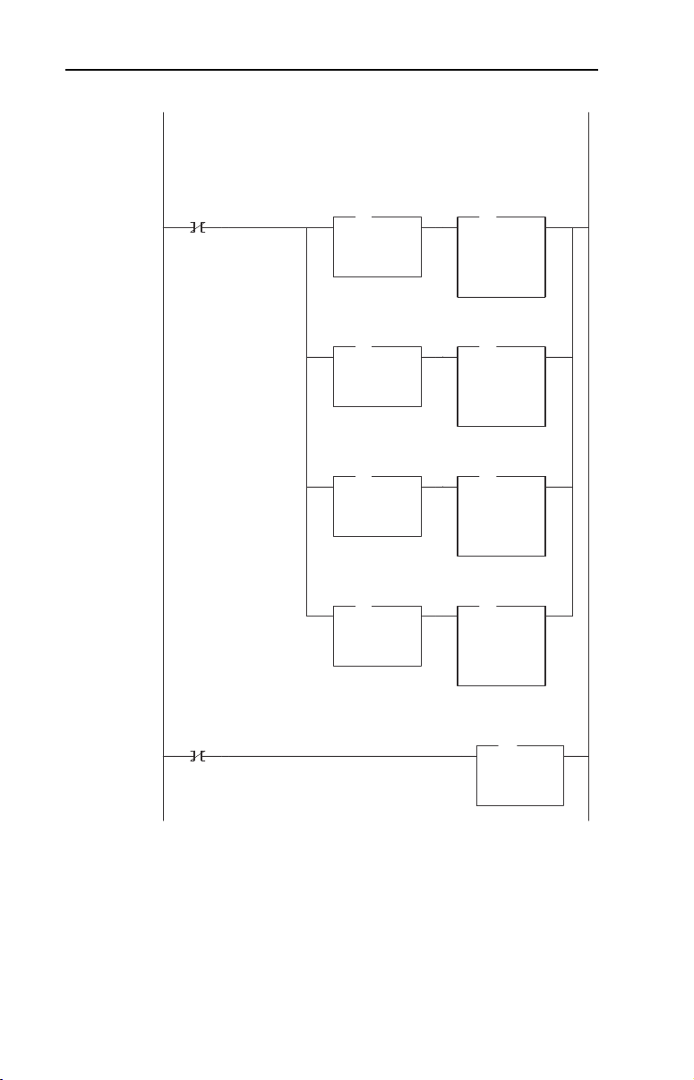
6-16 Using Explicit Messaging (PCP Communications)
Figure 6.3 LAD5 - PCP Read Subroutine (Continued)
N22:12 = Index (the parameter number or fault/event queue item to be read)
N22:1 determines what area is to be read:
0 = PowerFlex 70 (Host) parameter (N22:2 + 12288 decimal (3000h) = mapped parameter address)
1 = 20-COMM-I parameter (N22:2 + 12213 decimal (2FB5h) = mapped parameter address)
2 = PowerFlex 70 (Host) Fault queue (N22:2 + 12280 decimal (2FF8h) = mapped fault item)
3 = 20-COMM-I Event Queue (N22:2 + 12205 decimal (2FADh) = mapped event item)
PCP Read
Routine
1-shot
0002
0003
B3:47
1
N22:13 = Sub Index (Not used)
PCP Read
Routine
1-shot
B3:47
1
PCP Read
Param / Queue
to Read
EQU
EQU
Equal
Source A N22:1
0<
Source B 0
0<
PCP Read
Param / Queue
to Read
EQU
EQU
Equal
Source A N22:1
0<
Source B 1
1<
PCP Read
Param / Queue
to Read
EQU
EQU
Equal
Source A N22:1
0<
Source B 2
2<
PCP Read
Param / Queue
to Read
EQU
EQU
Equal
Source A N22:1
0<
Source B 3
3<
PCP Read
Command Msg
Index
ADD
ADD
Add
Source A N22:2
1<
Source B 12288
12288 <
Dest N22:12
12289 <
PCP Read
Command Msg
Index
ADD
ADD
Add
Source A N22:2
1<
Source B 12213
12213 <
Dest N22:12
12289 <
PCP Read
Command Msg
Index
ADD
ADD
Add
Source A N22:2
1<
Source B 12280
12280 <
Dest N22:12
12289 <
PCP Read
Command Msg
Index
ADD
ADD
Add
Source A N22:2
1<
Source B 12205
12205 <
Dest N22:12
12289 <
PCP Read
Command Msg
Sub Index
MOV
MOV
Move
Source 0
0<
Dest N22:13
0<
Page 79

Using Explicit Messaging (PCP Communications) 6-17
Figure 6.3 LAD5 - PCP Read Subroutine (Continued)
Copy the PCP Read Command message to the scanner for transmission on the network.
PCP Read
Routine
1-shot
0004
0005
0006
0007
0008
0009
B3:47
1
The PCP Read Command 1-shot is used so the subroutine processes and sends the Command only once when called by the
MAIN PGM
When the scanner acknowledges the PCP Read command, turn the Command word PCP Read bit OFF (originally comes from
N22:10 which was COPied to M0: above).
Status
PCP Read
M1:1.0
2
When the scanner Status word indicates that a message is available, copy the message for processing and handshake with the
scanner by turning the Command word Message Acknowledge bit ON.
Status
PCP Read
Message
Reply Msg
Present
1-Shot
M1:1.0
If the Reply contains only 1 byte of data, then the high and low bytes need to be swapped (e.g. a value of "5" will be stored as a
"0005" as opposed to "0500".
Status
Message
Present
M1:1.0
If the Reply does not contain 4 bytes of data, then the parameter is not 32-bit and Data Word #2 needs to be zero'd (might
contain leftover data from a previous 4-byte PCP Read).
Status
Message
Present
M1:1.0
B3:47
15
15
15
2
PCP Read
Reply Msg
1-Shot
B3:47
2
PCP Read
Reply Msg
1-Shot
B3:47
2
PCP Read
Reply Msg
# Bytes of Data
EQU
EQU
Equal
Source A N22:25
2<
Source B 1
1<
PCP Read
Reply Msg
# Bytes of Data
NEQ
Not Equal
Source A N22:25
2<
Source B 4
4<
Copy File
Source #N22:10
Dest #M0:1.0
Length 4
PCP Read
Reply Msg
Status Word
COP
COP
Copy File
Source #M1:1.0
Dest #N22:20
Length 8
PCP Read
Reply Msg
Data Word #1
Swap
Source #N22:26
Length 1
PCP Read
Reply Msg
Data Word #2
Move
Source 0
0<
Dest N22:27
0<
COP
COP
Command
Message
Acknowledge
M0:1.0
SWP
SWP
MOV
MOV
L
15
PCP Read
Routine
1-shot
B3:47
L
1
Command
PCP Read
M0:1.0
U
2
Page 80

6-18 Using Explicit Messaging (PCP Communications)
Figure 6.3 LAD5 - PCP Read Subroutine (Continued)
If the PCP Read Reply message indicates that the result was "not good" (N22:24 <> 0), then zero out the data area of the Reply
message (might contain leftover data from a previous successful PCP Read).
Status
PCP Read
Message
Reply Msg
Present
1-Shot
M1:1.0
0010
0011
0012
0013
15
The PCP Read Reply 1-shot is used so the subroutine processes the Reply message only once.
Status
Message
Present
M1:1.0
15
When the Command / Status Message handshake is complete, reset the 1-shot bits and exit the PCP Read routine by turning the
"Execute PCP Read" bit off (B3:47/0)
Command
Message
Acknowledge
M0:1.0
15
B3:47
2
Status
Message
Present
M1:1.0
15
PCP Read
Reply Msg
Result
NEQ
Not Equal
Source A N22:24
0<
Source B 0
0<
PCP Read
Reply Msg
Data Word #1
MOV
MOV
Move
Source 0
0<
Dest N22:26
325<
PCP Read
Reply Msg
Data Word #2
MOV
MOV
Move
Source 0
0<
Dest N22:27
0<
PCP Read
Reply Msg
1-Shot
Execute
PCP Read
Subroutine
B3:47
U
0
PCP Read
Routine
1-shot
B3:47
U
1
PCP Read
Reply Msg
1-Shot
B3:47
U
2
Command
Message
Acknowledge
M0:1.0
U
15
B3:47
L
2
END
Page 81

Using Explicit Messaging (PCP Communications) 6-19
PCP Write Subroutine (Explicit Messaging)
The PCP Write Subroutine is executed from the Main Program (Chapter
5) by turning on bit B3:47/10. Only one PCP Read or Write can be
performed at any one time. B3:47/10 will be turned off by the subroutine
when the reading is complete and signals that another read (or write)
cycle can take place.
Figure 6.4 LAD6 - PCP Write Subroutine
N23:10 = PCP Command Word (Set to "8" to cause a PCP Write: an "8" = bit 3 ON)
PCP Write
Routine
1-shot
0000
0001
0002
0003
B3:47
11
N23:11 = CR (The Communication Reference to write to. A unique CR is the established for each Station)
"2" = CR 2 = Station 1.0
"3" = CR 3 = Station 2.0
PCP Write
Routine
1-shot
B3:47
11
N23:12 = Index
N23:1 determines what area is to be written to:
0 = PowerFlex 70 (Host) parameter (N23:2 + 12288 decimal (3000h) = mapped parameter address)
1 = 20-COMM-I parameter (N23:2 + 12213 decimal (2FB5h) = mapped parameter address)
PCP Write
Routine
1-shot
B3:47
11
N23:13 = Sub Index (Not used)
PCP Write
Routine
1-shot
B3:47
11
PCP Write
Parameter Area
to Write
EQU
EQU
Equal
Source A N23:1
0<
Source B 0
0<
PCP Write
Parameter Area
to Write
EQU
EQU
Equal
Source A N23:1
0<
Source B 1
1<
PCP
Command
Word
MOV
MOV
Move
Source 8
8<
Dest N23:10
8<
PCP Write
Command Msg
CR
MOV
MOV
Move
Source N23:0
2<
Dest N23:11
2<
PCP Write
Command Msg
Index
ADD
ADD
Add
Source A N23:2
107<
Source B 12288
12288 <
Dest N23:12
12395 <
PCP Write
Command Msg
Index
ADD
ADD
Add
Source A N23:2
107<
Source B 12213
12213 <
Dest N23:12
12395 <
PCP Write
Command Msg
Sub Index
MOV
MOV
Move
Source 0
0<
Dest N23:13
0<
Page 82

6-20 Using Explicit Messaging (PCP Communications)
Figure 6.4 LAD6 - PCP Write Subroutine (Continued)
N23:14 = Number of bytes to write ("1" for byte, "2" for 16-bit parameter and "4" for 32-bit parameter)
Data is contained in:
N23:15 = Data word #1 to write (8-bit & 16-bit parameters, MSW of 32-bit parameters)
N23:16 = Data word #2 to write (LSW of 32-bit parameters)
If only 1 byte is being written, it needs to be loaded into the high byte of Data word #1 (N23:15). The subroutine performs this
via the SWP instruction so the main program can work with a normal number (i.e. a "2" instead of a "0200" hex).
PCP Write
Routine
1-shot
0004
0005
0006
0007
0008
B3:47
11
PCP Write
Command Msg
# Bytes of Data
EQU
EQU
Equal
Source A N23:14
2<
Source B 1
1<
Copy the PCP Write Command message to the scanner for transmission on the network.
PCP Write
Routine
1-shot
B3:47
11
The PCP Write Command 1-shot is used so the subroutine processes and sends the Command only once when called by the
MAIN PGM
When the scanner acknowledges the PCP Write command, turn the Command word PCP Write bit OFF (originally comes from
N23:10 which was COPied to M0: above).
Status
PCP Write
M1:1.0
3
When the scanner Status word indicates that a message is available, copy the message into an Interger file (N23:) for processing
and handshake with the scanner by turning the Command word Message Acknowledge bit ON.
Status
PCP Write
Message
Reply Msg
Present
1-Shot
M1:1.0
B3:47
15
12
PCP Write
Command Msg
# Bytes of Data
COP
COP
Copy File
Source #N23:3
Dest #N23:14
Length 3
SWP
SWP
Swap
Source #N23:15
Length 1
Copy File
Source #N23:10
Dest #M0:1.0
Length 7
PCP Write
Reply Msg
Status Word
COP
COP
Copy File
Source #M1:1.0
Dest #N23:20
Length 5
COP
COP
Command
Message
Acknowledge
M0:1.0
PCP Write
Routine
1-shot
Command
PCP Write
L
15
B3:47
11
M0:1.0
L
U
3
Page 83

Using Explicit Messaging (PCP Communications) 6-21
Figure 6.4 LAD6 - PCP Write Subroutine (Continued)
Status
Message
Present
M1:1.0
0009
0010
0011
15
When the Command / Status Message handshake is complete, reset the 1-shot bits and exit the PCP Write routine by turning the
"Execute PCP Write" bit off (B3:47/10)
Command
Message
Acknowledge
M0:1.0
Status
Message
Present
M1:1.0
15
15
PCP Write
Reply Msg
1-Shot
Execute
PCP Write
Subroutine
B3:47
U
10
PCP Write
Routine
1-shot
B3:47
U
11
PCP Write
Reply Msg
1-Shot
B3:47
U
12
Command
Message
Acknowledge
M0:1.0
U
15
B3:47
L
12
END
Page 84

6-22 Using Explicit Messaging (PCP Communications)
Notes:
Page 85

Chapter
PWR
STS
CC
RD
TR
BA
Troubleshooting
Chapter 7 contains troubleshooting information.
Topic Page Topic Page
Locating the Status Indicators
Cable Check (CC) Status
Indicator
Remote Bus Disable (RD) Status
Indicator
7-1 Transmit/Receive (TR) Status
7-2 Bus Active (BA) Status Indicator 7-3
7-2 Adapter Diagnostic Items 7-4
Indicator
Viewing and Clearing Events 7-5
Locating the Status Indicators
The Interbus adapter has five status indicators. They can be viewed on
the adapter or through the drive cover. See Figure 7.1
Figure 7.1 Status Indicators
.
➊
➋
➌
➍
➎
➊
➋
➌
➍
7-2
7
# Status Indicator Description Page
➊ CC Cable Check 7-2
➋ RD Remote Bus Disable 7-2
➌ TR Transmit/Receive 7-2
➍ BA Bus Active 7-3
➎ UL Bus Voltage 7-3
Page 86

7-2 Troubleshooting
Note: The UL indicator is not viewable when the drive cover is installed
or closed.
Note: Interbus compliance requires different LED functions than what is
normally displayed on the front of the drive (Port, Mod, Net A and Net B
Leds). LED labels are provided with the adapter for application to the
drive cover.
Cable Check (CC) Status Indicator
Status Cause Corrective Action
Off Master is reset or no cable
connection.
Solid Green Cable connection good.
Connect the adapter to the network using an
•
Interbus cable.
Verify master not in reset.
•
No Action.
•
Remote Bus Disable (RD) Status Indicator
Status Cause Corrective Action
Off Outgoing remote bus is not
Solid Red Outgoing remote bus is
switched off.
switched off.
No action.
•
Read configuration or start data
•
transmission. Master may have to be reset
first.
Transmit/Receive (TR) Status Indicator
Status Cause Corrective Actions
Off No PCP connection is
Solid Green A PCP connection is being
carried out.
carried out. Flashes when
a new PCP frame has
been received.
Verify that master is sending PCP
•
messages.
No action.
•
Page 87

Bus Active (BA) Status Indicator
Status Cause Corrective Actions
Off Bus not active.
Solid Green Bus active, exchanging
Flash Green Bus active, but no data
data.
exchange.
Set master to start data transmission.
•
No action.
•
Set master to start data transmission.
•
Troubleshooting 7-3
Bus Voltage (UL) Status Indicator
Status Cause Corrective Actions
Off Bus voltage is not OK.
Solid Green Bus active.
(1)
Only visible when drive cover is open.
Securely connect the adapter to the drive
•
using the Internal interface cable
Apply power to the drive.
•
No action.
•
(1)
Page 88

7-4 Troubleshooting
Adapter Diagnostic Items
Adapter Diagnostic Items are viewable with DriveExplorer (version 2.01
or higher), DriveExecutive (version v1.01 or higher) or LCD HIM (2.001
or higher) software. Diagnostic items show current data being
transmitted and received by the Host device (e.g. drive), and other
diagnostic information regarding the 20-COMM-I.
No. Event Description
1 Common Logic Cmd The current value of the Common Logic Command being transmitted
2 Prod Logic Cmd The current value of the Product-Specific Logic Command being
3 Reference The current value ofthe Product-Specific Reference being
4 Common Logic Sts The current value of the Product-Specific Logic Status being
5 Prod Logic Sts The current value of the Product-Specific Status being received from
6 Feedback The current value of the Product-Specific Feedback being received
7 Datalink A1 In The current value of Datalink A1 being transmitted to the Host.
8 Datalink A2 In The current value of Datalink A2 being transmitted to the Host.
9 Datalink B1 In The current value of Datalink B1 being transmitted to the Host.
10 Datalink B2 In The current value of Datalink B2 being transmitted to the Host.
11 Datalink C1 In The current value of Datalink C1 being transmitted to the Host.
12 Datalink C2 In The current value of Datalink C2 being transmitted to the Host.
13 Datalink D1 In The current value of Datalink D1 being transmitted to the Host.
14 Datalink D2 In The current value of Datalink D2 being transmitted to the Host.
15 Datalink A1 Out The current value of Datalink A1 being received from the Host.
16 Datalink A2 Out The current value of Datalink A2 being received from the Host.
17 Datalink B1 Out The current value of Datalink B1 being received from the Host.
18 Datalink B2 Out The current value of Datalink B2 being received from the Host.
19 Datalink C1 Out The current value of Datalink C1 being received from the Host.
20 Datalink C2 Out The current value of Datalink C2 being received from the Host.
21 Datalink D1 Out The current value of Datalink D1 being received from the Host.
22 Datalink D2 Out The current value of Datalink D2 being received from the Host.
23 Field Flash Cntr The number of times this device has been flash updated.
24 DPI Rx Err Cntr The current value of the DPI CAN Receive error counter.
25 DPI Tx Err Cntr The current value of the DPI CAN Transmit error counter.
26 IbusImage Siz Amount of process data bytes used on the Interbus network by the
to the Host.
transmitted to the Host.
transmitted to the Host.
received from the Host.
the Host.
from the Host.
(Value of 0 if Datalink is not used).
(Value of 0 if Datalink is not used).
(Value of 0 if Datalink is not used).
(Value of 0 if Datalink is not used).
(Value of 0 if Datalink not used).
(Value of 0 if Datalink is not used).
(Value of 0 if Datalink is not used).
(Value of 0 if Datalink is not used).
adapter.
Page 89

Troubleshooting 7-5
Viewing and Clearing Events
The adapter maintains an event queue that reports the history of its
actions. You can view the event queue using an LCD PowerFlex HIM,
DriveExplorer (2.01 or higher) software, or DriveExecutive (1.01 or
higher).
Step Keys Example Screen
Viewing Events
1. Access parameters in the adapter.
Refer to Using the PowerFlex HIM
Chapter 3.
2. Press the Up Arrow or Down Arrow to
scroll to Diagnostics.
3. Press Enter to display the
Diagnostics menu in the adapter.
4. Repeat steps 2 and 3 to enter the
Events option and then View Event
Queue option.
5. Press the Up Arrow or Down Arrow to
scroll through the events. The most
recent event is Event 1.
Clearing Events
1. Access parameters in the Adapter.
Refer to Using the PowerFlex HIM
Chapter
3.
2. Press the Up Arrow or Down Arrow to
scroll to Diagnostics.
3. Press Enter to display the
Diagnostics menu in the adapter.
4. Repeat steps 2 and 3 to enter the
Events option and then the Clr
Event option or Clear Event Queue
option. A message will pop up to
confirm that you want to clear the
message or queue.
5. Press Enter to clear all events out of
the event queue. All event queue
entries will then display “No Event.”
in
in
OR
OR
OR
Main Menu:
Diagnostics
Parameter
Device Select
Event Q: 1 E3
Ping Time Flt
Dgn: Events
View Event Queue
Clear Event
Clear Event Queue
Page 90

7-6 Troubleshooting
Events
Many events in the Event queue occur under normal operation. If you
encounter unexpected communications problems, the events may help
you or Allen-Bradley personnel troubleshoot the problem. The following
events may appear in the event queue:
Code Event Description
1 No Event Empty event queue entry.
2 DPI Bus Off
Flt
3 Ping Time Flt A ping message was not received on DPI within the specified
4 Port ID Flt The adapter is not connected to a correct port on a DPI product.
5 Port Change
Flt
6 Host Sent
Reset
7 EEPROM
Sum Flt
8 Online @
125kbps
9 Online @
500kbps
10 Bad Host Flt The adapter was connected to an incompatible product.
11 Dup. Port Flt Another peripheral with the same port number is already in use.
12 Type 0 Login The adapter has logged in for type 0 control.
13 Type 0 Time
Flt
14 DL Login The adapter has logged into a Datalink.
15 DL Reject Flt The host rejected an attempt to log in to a Datalink because the
16 DL Time Flt The adapter has not received a Datalink message within the
17 Control
Disabled
18 Control
Enabled
19 Message
Timeout
20 DPI Fault Msg The DPI Host has faulted.
21 DPI Fault
Clear
22 Normal
Startup
23 Net Comm Flt The adapter detected a fault condition on the Interbus network.
24 Fault Cfg
Error
A bus-off condition was detected on DPI. This event may be
caused by loose or broken cables or by noise.
time.
The DPI port changed.
The DPI product issued this because it was reset.
The EEPROM in the adapter is corrupt.
The adapter and DPI product are communicating at 125kbps.
The adapter and DPI product are communicating at 500kbps.
The adapter has not received a type 0 status message within
the specified time.
Datalink is not supported or is used by another peripheral.
specified time.
The adapter has sent a “Soft Control Disable” command to the
DPI product.
The adapter has sent a “Soft Control Enable” command to the
DPI product.
A Client-Server message sent by the peripheral was not
completed.
The user cleared a fault in the adapter.
Peripheral completes a normal startup.
The peripheral detected a 32-bit fault configuration Reference
when the Host supports only a 16-bit Reference, or vice-versa.
Page 91

Troubleshooting 7-7
Code Event Description
25 IB Online The Interbus adapter has gone on-line the Interbus network.
26 IB Offline The Interbus adapter has gone off-line the Interbus network.
27 Lang CRC
Bad
Language file CRC is Bad
Page 92

7-8 Troubleshooting
Notes:
Page 93

Appendix
Specifications
This chapter presents the specifications for the adapter.
Topic Page Topic Page
Communications
Electrical A-1 Regulatory Compliance A-2
Mechanical A-1
Communications
Network
Protocol
Data Rates
Drive
Protocol
Data Rates
A-1 Environmental A-2
Interbus
500K
DPI
125K or 500K
A
Electrical
Consumption
Drive
Network
450mA at 5 V supplied through the drive
Mechanical
Dimensions
Height
Length
Width
Weight 65g (2.3 oz.)
19 mm (0.75 inches)
86 mm (3.39 inches)
78.5 mm (3.09 inches)
Page 94

A-2 Specifications
Environmental
Temperature
Operating
Storage
Relative Humidity 5 to 95% non-condensing
-10 to 50
-40 to +85
C (14 to 149°F)
°
C (-40 to 185°F)
°
Regulatory Compliance
UL 508C and CUL
CE EN50081-2 (1993) and EN61000-6-2 (1999)
Page 95

Appendix
B
Adapter Parameters
Appendix B provides information about the Interbus adapter parameters.
Topic Page
About Parameter Numbers
Parameters List B-1
About Parameter Numbers
The parameters in the adapter are numbered consecutively. However,
depending on which configuration tool you use, they may have different
numbers.
Configuration Tool Numbering Scheme
DriveExplorer
•
DriveExecutive
•
HIM
•
Explicit Messaging
•
B-1
The adapter parameters begin with parameter 1. For
example, Parameter 01 - [DPI Port] is parameter 1 as
indicated by this manual.
Parameters List
Parameter
No. Name and Description Details
01 [DPI Port]
Port to which the adapter is connected. This will
usually be port 5.
02 [DPI Data Rate]
Data rate used by the drive. This data rate is set in
the drive, and the adapter detects it.
03 [Ref/Feedback Size]
Size of the Reference/Feedback. The drive
determines the size of the Reference/Feedback.
Default: 0
Minimum: 0
Maximum: 7
Type: Read Only
Default: 0 = 125 K
Values: 0 = 125 K
Type: Read Only
Default: 0 = 16-bit
Values: 0 = 16-bit
Type: Read Only
1 = 500 K
1 = 32-bit
Page 96

B-2 Adapter Parameters
Parameter
No. Name and Description Details
04 [Datalink Size]
Size of each Datalink word. The drive determines
the size of the Datalinks.
05 [Reset Module]
No action if set to “Ready.” Resets the adapter if
set to “Reset Module.” Restores the adapter to its
factory default settings if set to “Set Defaults.” This
parameter is a command. It will be reset to “0 =
Ready” after the command has been performed.
06 [Comm Flt Action]
Action that the adapter and drive take if the
adapter detects that Interbus communications
have been disrupted. This setting is effective only
if I/O that controls the drive is transmitted through
the adapter.
ATTENTION: Risk of injury or equipment damage exists. Parameter 6 - [Comm Flt
Action] lets you determine the action of the adapter and connected drive if
communications are disrupted. By default, this parameter faults the drive. You can
!
set this parameter so that the drive continues to run. Precautions should be taken to
ensure that the setting of this parameter does not create a hazard or injury or
equipment damage.
07 [Reserved] Default: 0
08 [DPI I/O Config]
I/O that is transferred through the adapter.
Bit
Default
Default: 0 = 16-bit
Values: 0 = 16-bit
Type: Read Only
Default: 0 = Ready
Values 0 = Ready
Type: Read/Write
Reset Required: No
Default: 0 = Fault
Values: 0 = Fault
Type: Read/Write
Reset Required: No
Val ue s: 0
Type:
Reset Required:
Default: xxx0 0001
Bit Values: 0 = I/O disabled
Type: Read/Write
Reset Required: Yes
Bit Definitions
01234576
0 = Cmd/Ref
10000xxx
1 = Datalink A
2 = Datalink B
3 = Datalink C
4 = Datalink D
5 = Not Used
6 = Not Used
7 = Not Used
1 = 32-bit
1 = Reset Module
2 = Set Defaults
1 = Stop
2 = Zero Data
3 = Hold Last
4 = Send Flt Cfg
1 = I/O enabled
ATTENTION: Risk of injury or equipment damage exists. If the adapter is
transmitting I/O that controls the drive, the drive may fault when you reset the
adapter. Determine how your drive will respond before resetting a connected
!
adapter.
Page 97

Parameter
No. Name and Description Details
09 [DPI I/O Active]
I/O that the adapter is actively transmitting. The
value of this parameter will usually be equal to the
value of Parameter 8 - DPI I/O Config.
Bit
Default
10 [Flt Cfg Logic]
Sets the Logic Command data that is sent to the
drive if any of the following is true:
Parameter 06 - [Comm Flt Action] is set to
•
Send Flt Cfg and communications are
disrupted.
The bit definitions will depend on the product to
which the adapter is connected.
11 [Flt Cfg Ref]
Sets the Reference data that is sent to the drive if
any of the following is true:
Parameter 06 - [Comm Flt Action] is set to
•
Send Flt Cfg and communications are
disrupted.
Default: xxx0 0001
Bit Values: 0 = I/O disabled
Type: Read Only
Bit Definitions
01234576
0 = Cmd/Ref
10000xxx
1 = Datalink A
2 = Datalink B
3 = Datalink C
4 = Datalink D
5 = Not Used
6 = Not Used
7 = Not Used
Default: 0000 0000 0000 0000
Minimum: 0000 0000 0000 0000
Maximum: 1111 1111 1111 1111
Type: Read/Write
Reset Required: No
Default: 0
Minimum: 0
Maximum: 4294967295
Type: Read/Write
Reset Required: No
Important: If the drive uses a 16-bit
Reference, the most significant word of this
value must be set to zero (0) or a fault will
occur.
12
[Flt Cfg A1]
13
[Flt Cfg A2]
14
[Flt Cfg B1]
15
[Flt Cfg B2]
16
[Flt Cfg C1]
17
[Flt Cfg C2]
18
[Flt Cfg D1]
19
[Flt Cfg D2]
Sets the data that is sent to the Datalink in the
drive if any of the following is true:
Parameter 06 - [Comm Flt Action] is set to
•
Send Flt Cfg and the communications are
disrupted.
20 PIDD W0 Cfg
Configured Process Input Data Description for
Word 0. PCP Object to use for Word 0 transmitted
to Interbus master.
21 PIDD W0 Actual
Actual Process Input Data Description for Word 0.
Default: 0
Default: 0
Default: 0
Default: 0
Default: 0
Default: 0
Default: 0
Default: 0
Minimum: 0
Maximum: 4294967295
Type: Read/Write
Reset Required: No
Important: If the drive uses 16-bit
Datalinks, the most significant word of this
value must be set to zero (0) or a fault will
occur.
Default: 0x2F9A
Setting: See Ta b l e B. 1
Type: Read/Write
Reset Required: No (becomes active
Value: See Table B.1
Type: Read Only
Adapter Parameters B-3
1 = I/O enabled
(Logic Status)
when Interbus network
is restarted)
Page 98

B-4 Adapter Parameters
Parameter
No. Name and Description Details
22 PIDD W1 Cfg
Configured Process Input Data Description for
Word 1. PCP Object to use for Word 1 transmitted
to Interbus master.
23 PIDD W1 Actual
Actual Process Input Data Description for Word 1.
24 PIDD W2 Cfg
Configured Process Input Data Description for
Word 2. PCP Object to use for Word 2 transmitted
to Interbus master.
25 PIDD W2 Actual
Actual Process Input Data Description for Word 2.
26 PIDD W3 Cfg
Configured Process Input Data Description for
Word 3. PCP Object to use for Word 3 transmitted
to Interbus master.
27 PIDD W3 Actual
Actual Process Input Data Description for Word 3.
28 PIDD W4 Cfg
Configured Process Input Data Description for
Word 4. PCP Object to use for Word 4 transmitted
to Interbus master.
29 PIDD W4 Actual
Actual Process Input Data Description for Word 4.
30 PIDD W5 Cfg
Configured Process Input Data Description for
Word 5. PCP Object to use for Word 5 transmitted
to Interbus master.
31 PIDD W5 Actual
Actual Process Input Data Description for Word 5.
32 PIDD W6 Cfg
Configured Process Input Data Description for
Word 6. PCP Object to use for Word 6 transmitted
to Interbus master.
33 PIDD W6 Actual
Actual Process Input Data Description for Word 6.
34 PIDD W7 Cfg
Configured Process Input Data Description for
Word 7. PCP Object to use for Word 7 transmitted
to Interbus master.
Default: 0x2F9B
Setting: See Ta b l e B. 1
Type: Read/Write
Reset Required: No (becomes active
Val ue : S ee Ta bl e B. 1
Type: Read Only
Default: 0
Setting: See Ta b l e B. 1
Type: Read/Write
Reset Required: No (becomes active
Val ue : S ee Ta bl e B. 1
Type: Read Only
Default: 0
Setting: See Ta b l e B. 1
Type: Read/Write
Reset Required: No (becomes active
Val ue : S ee Ta bl e B. 1
Type: Read Only
Default: 0
Setting: See Ta b l e B. 1
Type: Read/Write
Reset Required: No (becomes active
Val ue : S ee Ta bl e B. 1
Type: Read Only
Default: 0
Setting: See Ta b l e B. 1
Type: Read/Write
Reset Required: No (becomes active
Val ue : S ee Ta bl e B. 1
Type: Read Only
Default: 0
Setting: See Ta b l e B. 1
Type: Read/Write
Reset Required: No (becomes active
Val ue : S ee Ta bl e B. 1
Type: Read Only
Default: 0
Setting: See Ta b l e B. 1
Type: Read/Write
Reset Required: No (becomes active
(Feedback)
when Interbus network
is restarted)
when Interbus network
is restarted)
when Interbus network
is restarted)
when Interbus network
is restarted)
when Interbus network
is restarted)
when Interbus network
is restarted)
when Interbus network
is restarted)
Page 99

Parameter
No. Name and Description Details
35 PIDD W7 Actual
Actual Process Input Data Description for Word 7.
36 PIDD W8 Cfg
Configured Process Input Data Description for
Word 8. PCP Object to use for Word 8 transmitted
to Interbus master.
37 PIDD W8 Actual
Actual Process Input Data Description for Word 8.
38 PODD W0 Cfg
Configured Process Output Data Description for
Word 0. PCP Object to use for Word 0 received
from Interbus master.
39 PODD W0 Actual
Actual Process Output Data Description for Word
0.
40 PODD W1 Cfg
Configured Process Output Data Description for
Word 1. PCP Object to use for Word 1 received
from Interbus master.
41 PODD W1 Actual
Actual Process Output Data Description for Word
1.
42 PODD W2 Cfg
Configured Process Output Data Description for
Word 2. PCP Object to use for Word 2 received
from Interbus master.
43 PODD W2 Actual
Actual Process Output Data Description for Word
2.
44 PODD W3 Cfg
Configured Process Output Data Description for
Word 3. PCP Object to use for Word 3 received
from Interbus master.
45 PODD W3 Actual
Actual Process Output Data Description for Word
3.
46 PODD W4 Cfg
Configured Process Output Data Description for
Word 4. PCP Object to use for Word 4 received
from Interbus master.
Value: See Table B.1
Type: Read Only
Default: 0
Setting: See Ta b l e B. 1
Type: Read/Write
Reset Required: No (becomes active
Value: See Table B.1
Type: Read Only
Default: 0x2F98
Setting: See Ta b l e B. 1
Type: Read/Write
Reset Required: No (becomes active
Value: See Table B.1
Type: Read Only
Default: 0x2F99
Setting: See Ta b l e B. 1
Type: Read/Write
Reset Required: No (becomes active
Value: See Table B.1
Type: Read Only
Default: 0
Setting: See Ta b l e B. 1
Type: Read/Write
Reset Required: No (becomes active
Value: See Table B.1
Type: Read Only
Default: 0
Setting: See Ta b l e B. 1
Type: Read/Write
Reset Required: No (becomes active
Value: See Table B.1
Type: Read Only
Default: 0
Setting: See Ta b l e B. 1
Type: Read/Write
Reset Required: No (becomes active
Adapter Parameters B-5
when Interbus network
is restarted)
(Logic Command)
when Interbus network
is restarted)
(Reference)
when Interbus network
is restarted)
when Interbus network
is restarted)
when Interbus network
is restarted)
when Interbus network
is restarted)
Page 100

B-6 Adapter Parameters
Parameter
No. Name and Description Details
47 PODD W4 Actual
Actual Process Output Data Description for Word
4.
48 PODD W5 Cfg
Configured Process Output Data Description for
Word 5. PCP Object to use for Word 5 received
from Interbus master.
49 PODD W5 Actual
Actual Process Output Data Description for Word
5.
50 PODD W6 Cfg
Configured Process Output Data Description for
Word 6. PCP Object to use for Word 6 received
from Interbus master.
51 PODD W6 Actual
Actual Process Output Data Description for Word
6.
52 PODD W7 Cfg
Configured Process Output Data Description for
Word 7. PCP Object to use for Word 7 received
from Interbus master.
53 PODD W7 Actual
Actual Process Output Data Description for Word
7.
54 PODD W8 Cfg
Configured Process Output Data Description for
Word 8. PCP Object to use for Word 8 received
from Interbus master.
55 PODD W8 Actual
Actual Process Output Data Description for Word
8.
56 PCP Comm Cfg
Enable Interbus PCP communications.
57 PCP Comm Act
Actual PCP Configuration
Val ue : S ee Ta bl e B. 1
Type: Read Only
Default: 0
Setting: See Ta b l e B. 1
Type: Read/Write
Reset Required: No (becomes active
Val ue : S ee Ta bl e B. 1
Type: Read Only
Default: 0
Setting: See Ta b l e B. 1
Type: Read/Write
Reset Required: No (becomes active
Val ue : S ee Ta bl e B. 1
Type: Read Only
Default: 0
Setting: See Ta b l e B. 1
Type: Read/Write
Reset Required: No (becomes active
Val ue : S ee
Type: Read Only
Default: 0
Setting: See Ta b l e B. 1
Type: Read/Write
Reset Required: No (becomes active
Val ue : S ee Ta bl e B. 1
Type: Read Only
Default: 1 = Enable
Val ues : 0 = Di sa bl e
Type: Read/Write
Default: 1 = Enable
Val ues : 0 = Di sa bl e
Type: Read Only
when Interbus network
is restarted)
when Interbus network
is restarted)
when Interbus network
is restarted)
when Interbus network
is restarted)
1= Enable
1= Enable
 Loading...