

Page 1

PowerFlex 20-COMM-D
DeviceNet Adapter
Series B FRN 2.xxx
User Manual
Page 2
Important User Information
!
!
Solid state equipment has operational characteristics differing from those of
electromechanical equipment. Safety Guidelines for the Application,
Installation and Maintenance of Solid State Controls (Publication SGI-1.1
available from your local Rockwell Automation sales office or online at
www.rockwellautomation.com/literature) describes some important differences
between solid state equipment and hard-wired electromechanical devices.
Because of this difference, and also because of the wide variety of uses for solid
state equipment, all persons responsible for applying this equipment must
satisfy themselves that each intended application of this equipment is
acceptable.
In no event will Rockwell Automation, Inc. be responsible or liable for indirect
or consequential damages resulting from the use or application of this
equipment.
The examples and diagrams in this manual are included solely for illustrative
purposes. Because of the many variables and requirements associated with any
particular installation, Rockwell Automation, Inc. cannot assume responsibility
or liability for actual use based on the examples and diagrams.
No patent liability is assumed by Rockwell Automation, Inc. with respect to use
of information, circuits, equipment, or software described in this manual.
Reproduction of the contents of this manual, in whole or in part, without
written permission of Rockwell Automation, Inc. is prohibited.
http://
Throughout this manual, when necessary we use notes to make you aware of
safety considerations.
WARNING: Identifies information about practices or
circumstances that can cause an explosion in a hazardous
environment, which may lead to personal injury or death, property
damage, or economic loss.
Important: Identifies information that is critical for successful application and
understanding of the product.
ATTENTION: Identifies information about practices or
circumstances that can lead to personal injury or death, property
damage, or economic loss. Attentions help you identify a hazard,
avoid a hazard, and recognize the consequences.
Shock Hazard labels may be located on or inside the equipment
(e.g., drive or motor) to alert people that dangerous voltage may be
present.
Burn Hazard labels may be located on or inside the equipment
(e.g., drive or motor) to alert people that surfaces may be at
dangerous temperatures.
Allen-Bradley, Rockwell Software, Rockwell Automation, TechConnect, PowerFlex, SMC Flex, DPI, SCANport, Connected Components
Workbench, DriveExplorer, DriveExecutive, DriveTools, ControlFLASH, RSLogix, RSNetWorx for DeviceNet, ControlLogix, PLC-5,
and SLC 500 are trademarks of Rockwell Automation, Inc.
DeviceNet is a trademark used under license by ODVA.
Windows and Microsoft are registered trademarks of Microsoft Corporation.
20-COMM-D DeviceNet Adapter User Manual
Page 3

Summary of Changes
The information below summarizes the changes made to this manual since
its last release (May 2012).
Description of Changes Page
Added information about Connected Components Workbench software configuration
tool for drives and connected peripherals.
Added information for use with PowerFlex Digital DC drives.
Throughout
manual
20-COMM-D DeviceNet Adapter User Manual
Publication 20COMM-UM002G-EN-P
Page 4

soc-ii Summary of Changes
Notes:
20-COMM-D DeviceNet Adapter User Manual
Publication 20COMM-UM002G-EN-P
Page 5

Preface About This Manual
Conventions Used in This Manual . . . . . . . . . . . . . . . . . . . . . . . . . . . . . . . . . . . . . . . . . . P-1
Rockwell Automation Support . . . . . . . . . . . . . . . . . . . . . . . . . . . . . . . . . . . . . . . . . . . . . P-2
Additional Resources . . . . . . . . . . . . . . . . . . . . . . . . . . . . . . . . . . . . . . . . . . . . . . . . . . . . P-2
Chapter 1 Getting Started
Components. . . . . . . . . . . . . . . . . . . . . . . . . . . . . . . . . . . . . . . . . . . . . . . . . . . . . . . . . . . . 1-1
Features . . . . . . . . . . . . . . . . . . . . . . . . . . . . . . . . . . . . . . . . . . . . . . . . . . . . . . . . . . . . . . . 1-2
Compatible Products . . . . . . . . . . . . . . . . . . . . . . . . . . . . . . . . . . . . . . . . . . . . . . . . . . . . . 1-3
Required Equipment . . . . . . . . . . . . . . . . . . . . . . . . . . . . . . . . . . . . . . . . . . . . . . . . . . . . . 1-3
Safety Precautions. . . . . . . . . . . . . . . . . . . . . . . . . . . . . . . . . . . . . . . . . . . . . . . . . . . . . . . 1-5
Quick Start . . . . . . . . . . . . . . . . . . . . . . . . . . . . . . . . . . . . . . . . . . . . . . . . . . . . . . . . . . . . 1-6
Chapter 2 Installing the Adapter
Preparing for an Installation . . . . . . . . . . . . . . . . . . . . . . . . . . . . . . . . . . . . . . . . . . . . . . . 2-1
Setting the Node Address Switches . . . . . . . . . . . . . . . . . . . . . . . . . . . . . . . . . . . . . . . . . 2-2
Setting the Data Rate Switch. . . . . . . . . . . . . . . . . . . . . . . . . . . . . . . . . . . . . . . . . . . . . . . 2-3
Connecting the Adapter to the Drive. . . . . . . . . . . . . . . . . . . . . . . . . . . . . . . . . . . . . . . . . 2-4
Connecting the Adapter to the Network . . . . . . . . . . . . . . . . . . . . . . . . . . . . . . . . . . . . . . 2-7
Applying Power. . . . . . . . . . . . . . . . . . . . . . . . . . . . . . . . . . . . . . . . . . . . . . . . . . . . . . . . . 2-8
Commissioning the Adapter . . . . . . . . . . . . . . . . . . . . . . . . . . . . . . . . . . . . . . . . . . . . . . 2-10
Table of Contents
Chapter 3 Configuring the Adapter
Configuration Tools. . . . . . . . . . . . . . . . . . . . . . . . . . . . . . . . . . . . . . . . . . . . . . . . . . . . . . 3-1
Using the PowerFlex 7-Class HIM to Access Parameters . . . . . . . . . . . . . . . . . . . . . . . . 3-2
Setting the Node Address . . . . . . . . . . . . . . . . . . . . . . . . . . . . . . . . . . . . . . . . . . . . . . . . . 3-3
Setting the Data Rate. . . . . . . . . . . . . . . . . . . . . . . . . . . . . . . . . . . . . . . . . . . . . . . . . . . . . 3-3
Setting the I/O Configuration . . . . . . . . . . . . . . . . . . . . . . . . . . . . . . . . . . . . . . . . . . . . . . 3-4
Selecting Master-Slave or Peer-to-Peer Hierarchy . . . . . . . . . . . . . . . . . . . . . . . . . . . . . . 3-5
Selecting COS, Cyclic or Polled I/O. . . . . . . . . . . . . . . . . . . . . . . . . . . . . . . . . . . . . . . . 3-10
Setting a Fault Action . . . . . . . . . . . . . . . . . . . . . . . . . . . . . . . . . . . . . . . . . . . . . . . . . . . 3-11
Resetting the Adapter . . . . . . . . . . . . . . . . . . . . . . . . . . . . . . . . . . . . . . . . . . . . . . . . . . . 3-12
Viewing the Adapter Status Using Parameters . . . . . . . . . . . . . . . . . . . . . . . . . . . . . . . . 3-13
Updating the Adapter Firmware . . . . . . . . . . . . . . . . . . . . . . . . . . . . . . . . . . . . . . . . . . . 3-14
Chapter 4 Configuring the I/O
Using RSLinx Classic Software . . . . . . . . . . . . . . . . . . . . . . . . . . . . . . . . . . . . . . . . . . . . 4-1
ControlLogix Controller Example . . . . . . . . . . . . . . . . . . . . . . . . . . . . . . . . . . . . . . . . . . 4-2
PLC-5 Controller Example . . . . . . . . . . . . . . . . . . . . . . . . . . . . . . . . . . . . . . . . . . . . . . . 4-20
SLC 500 Controller Example . . . . . . . . . . . . . . . . . . . . . . . . . . . . . . . . . . . . . . . . . . . . . 4-31
20-COMM-D DeviceNet Adapter User Manual
Publication 20COMM-UM002G-EN-P
Page 6

ii Table of Contents
Chapter 5 Using the I/O
About I/O Messaging. . . . . . . . . . . . . . . . . . . . . . . . . . . . . . . . . . . . . . . . . . . . . . . . . . . . . 5-1
Understanding the I/O Image. . . . . . . . . . . . . . . . . . . . . . . . . . . . . . . . . . . . . . . . . . . . . . . 5-2
Using Logic Command/Status. . . . . . . . . . . . . . . . . . . . . . . . . . . . . . . . . . . . . . . . . . . . . . 5-6
Using Reference/Feedback . . . . . . . . . . . . . . . . . . . . . . . . . . . . . . . . . . . . . . . . . . . . . . . . 5-6
Using Datalinks . . . . . . . . . . . . . . . . . . . . . . . . . . . . . . . . . . . . . . . . . . . . . . . . . . . . . . . . . 5-9
Example Ladder Logic Program Information . . . . . . . . . . . . . . . . . . . . . . . . . . . . . . . . . 5-11
ControlLogix Controller Example. . . . . . . . . . . . . . . . . . . . . . . . . . . . . . . . . . . . . . . . . . 5-12
PLC-5 Controller Example . . . . . . . . . . . . . . . . . . . . . . . . . . . . . . . . . . . . . . . . . . . . . . . 5-19
SLC 500 Controller Example . . . . . . . . . . . . . . . . . . . . . . . . . . . . . . . . . . . . . . . . . . . . . 5-32
Chapter 6 Using Explicit Messaging
About Explicit Messaging . . . . . . . . . . . . . . . . . . . . . . . . . . . . . . . . . . . . . . . . . . . . . . . . . 6-2
Performing Explicit Messaging . . . . . . . . . . . . . . . . . . . . . . . . . . . . . . . . . . . . . . . . . . . . . 6-3
ControlLogix Controller Examples . . . . . . . . . . . . . . . . . . . . . . . . . . . . . . . . . . . . . . . . . . 6-4
PLC-5 Controller Examples . . . . . . . . . . . . . . . . . . . . . . . . . . . . . . . . . . . . . . . . . . . . . . 6-19
SLC 500 Controller Examples. . . . . . . . . . . . . . . . . . . . . . . . . . . . . . . . . . . . . . . . . . . . . 6-27
Chapter 7 Troubleshooting
Understanding the Status Indicators . . . . . . . . . . . . . . . . . . . . . . . . . . . . . . . . . . . . . . . . . 7-1
PORT Status Indicator . . . . . . . . . . . . . . . . . . . . . . . . . . . . . . . . . . . . . . . . . . . . . . . . . . . . 7-2
MOD Status Indicator . . . . . . . . . . . . . . . . . . . . . . . . . . . . . . . . . . . . . . . . . . . . . . . . . . . . 7-2
NET A Status Indicator . . . . . . . . . . . . . . . . . . . . . . . . . . . . . . . . . . . . . . . . . . . . . . . . . . . 7-3
Viewing Adapter Diagnostic Items . . . . . . . . . . . . . . . . . . . . . . . . . . . . . . . . . . . . . . . . . . 7-4
Viewing and Clearing Events. . . . . . . . . . . . . . . . . . . . . . . . . . . . . . . . . . . . . . . . . . . . . . . 7-6
Chapter 8 Using the Adapter in a DPI External Comms Kit (20-XCOMM-DC-BASE)
Installing the Adapter . . . . . . . . . . . . . . . . . . . . . . . . . . . . . . . . . . . . . . . . . . . . . . . . . . . . 8-1
I/O Board Option (20-XCOMM-IO-OPT1) . . . . . . . . . . . . . . . . . . . . . . . . . . . . . . . . . . . 8-2
Understanding the I/O Image (Drive + I/O Option) . . . . . . . . . . . . . . . . . . . . . . . . . . . . . 8-2
Configuring the Adapter to Use the Optional I/O Data. . . . . . . . . . . . . . . . . . . . . . . . . . . 8-3
Viewing Optional I/O Diagnostic Items . . . . . . . . . . . . . . . . . . . . . . . . . . . . . . . . . . . . . . 8-4
Appendix A Specifications
Communications . . . . . . . . . . . . . . . . . . . . . . . . . . . . . . . . . . . . . . . . . . . . . . . . . . . . . . . . A-1
Electrical . . . . . . . . . . . . . . . . . . . . . . . . . . . . . . . . . . . . . . . . . . . . . . . . . . . . . . . . . . . . . . A-1
Mechanical. . . . . . . . . . . . . . . . . . . . . . . . . . . . . . . . . . . . . . . . . . . . . . . . . . . . . . . . . . . . . A-1
Environmental . . . . . . . . . . . . . . . . . . . . . . . . . . . . . . . . . . . . . . . . . . . . . . . . . . . . . . . . . . A-2
Regulatory Compliance . . . . . . . . . . . . . . . . . . . . . . . . . . . . . . . . . . . . . . . . . . . . . . . . . . . A-2
Appendix B Adapter Parameters
About Parameter Numbers. . . . . . . . . . . . . . . . . . . . . . . . . . . . . . . . . . . . . . . . . . . . . . . . . B-1
Parameter List . . . . . . . . . . . . . . . . . . . . . . . . . . . . . . . . . . . . . . . . . . . . . . . . . . . . . . . . . . B-1
20-COMM-D DeviceNet Adapter User Manual
Publication 20COMM-UM002G-EN-P
Page 7

Appendix C DeviceNet Objects
Identity Object. . . . . . . . . . . . . . . . . . . . . . . . . . . . . . . . . . . . . . . . . . . . . . . . . . . . . . . . . . C-2
Connection Object. . . . . . . . . . . . . . . . . . . . . . . . . . . . . . . . . . . . . . . . . . . . . . . . . . . . . . . C-3
Register Object . . . . . . . . . . . . . . . . . . . . . . . . . . . . . . . . . . . . . . . . . . . . . . . . . . . . . . . . . C-4
Parameter Object. . . . . . . . . . . . . . . . . . . . . . . . . . . . . . . . . . . . . . . . . . . . . . . . . . . . . . . . C-5
Parameter Group Object . . . . . . . . . . . . . . . . . . . . . . . . . . . . . . . . . . . . . . . . . . . . . . . . . . C-7
PCCC Object. . . . . . . . . . . . . . . . . . . . . . . . . . . . . . . . . . . . . . . . . . . . . . . . . . . . . . . . . . . C-8
DPI Device Object . . . . . . . . . . . . . . . . . . . . . . . . . . . . . . . . . . . . . . . . . . . . . . . . . . . . . C-11
DPI Parameter Object . . . . . . . . . . . . . . . . . . . . . . . . . . . . . . . . . . . . . . . . . . . . . . . . . . . C-13
DPI Fault Object . . . . . . . . . . . . . . . . . . . . . . . . . . . . . . . . . . . . . . . . . . . . . . . . . . . . . . . C-17
DPI Alarm Object . . . . . . . . . . . . . . . . . . . . . . . . . . . . . . . . . . . . . . . . . . . . . . . . . . . . . . C-19
DPI Diagnostic Object . . . . . . . . . . . . . . . . . . . . . . . . . . . . . . . . . . . . . . . . . . . . . . . . . . C-21
DPI Time Object . . . . . . . . . . . . . . . . . . . . . . . . . . . . . . . . . . . . . . . . . . . . . . . . . . . . . . . C-22
Appendix D Logic Command/Status Words
PowerFlex 70/700/700H, and 700L (with 700 Control) Drives . . . . . . . . . . . . . . . . . . . . D-1
PowerFlex 700S (Phase II Control) and 700L (with 700S Control) Drives . . . . . . . . . . . D-3
PowerFlex 750-Series Drives . . . . . . . . . . . . . . . . . . . . . . . . . . . . . . . . . . . . . . . . . . . . . . D-5
PowerFlex Digital DC Drives . . . . . . . . . . . . . . . . . . . . . . . . . . . . . . . . . . . . . . . . . . . . . . D-7
Table of Contents iii
Appendix E Master-Slave I/O Configuration
M-S Input Parameter Configurations . . . . . . . . . . . . . . . . . . . . . . . . . . . . . . . . . . . . . . . . E-1
M-S Output Parameter Configurations . . . . . . . . . . . . . . . . . . . . . . . . . . . . . . . . . . . . . . . E-4
Glossary
Index
20-COMM-D DeviceNet Adapter User Manual
Publication 20COMM-UM002G-EN-P
Page 8

iv Table of Contents
20-COMM-D DeviceNet Adapter User Manual
Publication 20COMM-UM002G-EN-P
Page 9

Preface
About This Manual
Topic Page
Additional Resources
Rockwell Automation Support P-2
Conventions Used in This Manual P-1
This manual provides information about the adapter and using it with
PowerFlex 7-Class (Architecture-Class) drives. The adapter can be used
with other products that support a DPI™ adapter, such as the DPI External
Comms Kit (20-XCOMM-DC-BASE). See the documentation for your
product for specific information about how it works with the adapter.
P-2
Conventions Used in This Manual
The following conventions are used throughout this manual:
• Parameter names are shown in the format Parameter xx - [*]. The xx
represents the parameter number. The * represents the parameter name
— for example Parameter 01 - [DPI Port].
• Menu commands are shown in bold type face and follow the format
Menu > Command. For example, if you read ‘Select File > Open’, you
should click the File menu and then click the Open command.
• The firmware revision number (FRN) is displayed as FRN X.xxx, where
‘X’ is the major revision number and ‘xxx’ is the minor revision number.
• The screen images in this manual resulted from using the following
software:
®
– RSLinx
– RSNetWorx
– RSLogix
– RSLogix 500 software, version 7.20
– RSLogix 5000 software, version 16.00
Different versions of the software may have screens that vary in
appearance, and differences in procedures.
Classic software, version 2.51
™
for DeviceNet software, version 7.00
™
5 software, version 7.20
20-COMM-D DeviceNet Adapter User Manual
Publication 20COMM-UM002G-EN-P
Page 10

P-2 About This Manual
Rockwell Automation Support
Rockwell Automation offers support services worldwide, with over 75 sales
and support offices, over 500 authorized distributors, and over 250
authorized systems integrators located throughout the United States alone.
In addition, Rockwell Automation representatives are in every major
country in the world.
Local Product Support
Contact your local Rockwell Automation, Inc. representative for:
• Sales and order support
• Product technical training
• Warranty support
• Support service agreements
Technical Product Assistance
For technical assistance, please review the information in Chapter 7,
Troubleshooting
Allen-Bradley Technical Support website at www.ab.com/support/abdrives
or contact Rockwell Automation.
, first. If you still have problems, then access the
Additional Resources
Resource Description
PowerFlex 7-Class DPI (Drive Peripheral Interface) Network Communication Adapter Installation
Instructions, publication 20COMM-IN004
DeviceNet Media Design and Installation Guide, publication DNET-UM072
DeviceNet Starter Kit User Manual, publication DNET-UM003
Connected Components Workbench website http://www.ab.com/support/abdrives/webupdate/
software.html, and online help
DriveExplorer website http://www.ab.com/drives/driveexplorer
DriveExecutive website http://www.ab.com/drives/drivetools
PowerFlex 20-HIM-A3/-A5/-C3S/-C5S HIM Quick Reference, publication 20HIM-QR001
PowerFlex 20-HIM-A6/C6S HIM (Human Interface Module) User Manual, publication 20HIM-UM001
PowerFlex 70 User Manual, publication 20A-UM001
PowerFlex 70/700 Reference Manual, publication PFLEX-RM001
PowerFlex 70 Enhanced Control and 700 Vector Control Reference Manual, publication PFLEX-RM004
PowerFlex 700 Series A User Manual, publication 20B-UM001
PowerFlex 700 Series B User Manual, publication 20B-UM002
PowerFlex 70/700 Reference Manual, publication PFLEX-RM001
PowerFlex 70 Enhanced Control and 700 Vector Control Reference Manual, publication PFLEX-RM004
PowerFlex 700H Installation Instructions, publication PFLEX-IN006
PowerFlex 700H Programming Manual, publication 20C-PM001
(1)
These documents contain additional information concerning related
products from Rockwell Automation.
Information on installing PowerFlex
Communication Adapters.
, and online help
Information on planning, installation, and techniques used to
, and online help
(1)
(1)
Information on using the PowerFlex 20-HIM-A3, 20-HIM-A5,
implement a DeviceNet™ network.
Information on the Connected Components Workbench
software tool—and includes a link for free software download.
Information on using the DriveExplorer™ software tool.
Information on using the DriveExecutive™ software tool.
20-HIM-C3S, and 20-HIM-C5S HIMs.
Information on installing and using PowerFlex 20-HIM-A6 and
20-HIM-C6S HIMs.
Information on installing and programming PowerFlex 70
standard control and enhanced control drives.
Information on installing and programming PowerFlex 700
standard control and vector control Series A drives, and
PowerFlex 700 vector control Series B drives.
Information on installing and programming PowerFlex 700H
drives.
®
20-COMM-x Network
20-COMM-D DeviceNet Adapter User Manual
Publication 20COMM-UM002G-EN-P
Page 11
Resource Description
PowerFlex 700S w/Phase I Control Installation Manual (Frames 1…6), publication 20D-IN024
PowerFlex 700S w/Phase I Control Installation Manual (Frames 9 and 10), publication PFLEX-IN006
PowerFlex 700S w/Phase I Control User Manual (All Frame Sizes), publication 20D-UM001
PowerFlex 700S w/Phase I Control Reference Manual, publication PFLEX-RM002
PowerFlex 700S w/Phase II Control Installation Manual (Frames 1…6), publication 20D-IN024
PowerFlex 700S w/Phase II Control Installation Manual (Frames 9…14), publication PFLEX-IN006
PowerFlex 700S w/Phase II Control Programming Manual (All Frame Sizes), publication 20D-PM001
PowerFlex 700S w/Phase II Control Reference Manual, publication PFLEX-RM003
PowerFlex 700L User Manual, publication 20L-UM001
PowerFlex 750-Series Drive Installation Instructions, publication 750-IN001
PowerFlex 750-Series Drive Programming Manual, publication 750-PM001
PowerFlex 20-750-DNET DeviceNet Option Module, publication 750COM-UM002
20-750-20COMM and 20-750COMM-F1 Communication Carrier Cards Installation Instructions,
publication 750COM-IN001
PowerFlex Digital DC Drive User Manual, publication 20P-UM001
Getting Results with RSLinx Guide, publication LINX-GR001
RSLogix Emulate 5/500 Getting Results Guide, publication EMULAT-GR002
RSLogix 500 Getting Results Guide, publication LG500-GR002
RSLogix 5000 PIDE Autotuner Getting Results Guide, publication PIDE-GR001
RSNetWorx for DeviceNet Getting Results Guide, publication DNET-GR001
DeviceNet Network Configuration User Manual, publication DNET-UM004
DeviceNet Scanner Module Installation Instructions, publication 1771-IN014
PLC-5 DeviceNet Scanner Module User Manual, publication 1771-UM118
1747-SDN DeviceNet Scanner Module Installation Instructions, publication 1747-IN058
1747-SDN DeviceNet Scanner Module User Manual, publication 1747-UM655
(1)
The online help is installed with the software.
Information on installing and programming PowerFlex 700L
Information on installing and programming PowerFlex Digital
, and online help
, and online help
(1)
, and online help
(1)
, and online help
, and online help
Information on using DeviceNet modules with the Logix 5000
Information on installing the 1771-SDN/C Scanner Module.
Information on configuring a DeviceNet network using RSLinx
Information on configuring a DeviceNet network by using
Information on installing the 1747-SDN DeviceNet Scanner
Information on installing and programming PowerFlex 700S
drives.
Liquid-Cooled AC drives.
Information on installing and programming PowerFlex
750-Series AC drives.
DC drives.
Information on using RSLinx Classic software.
(1)
Information on installing and navigating the RSLogix Emulate
software for ladder logic programming with Allen-Bradley
PLC-5 and SLC 500 processors.
Information on using the RSLogix 500 software tool.
(1)
Information on using the RSLogix 5000 software tool.
(1)
Information on installing and navigating the RSNetWorx for
DeviceNet™ software, effectively using it, and accessing and
navigating the online help.
controller and communicating with various devices on the
DeviceNet network.
and RSNetWorx for DeviceNet software.
Module.
RSLinx and RSNetWorx for DeviceNet software.
About This Manual P-3
Documentation can obtained online at http://
literature.rockwellautomation.com. To order paper copies of technical
documentation, contact your local Rockwell Automation distributor or sales
representative.
To find your local Rockwell Automation distributor or sales representative,
visit http://www.rockwellautomation.com/locations
.
For information such as firmware updates or answers to drive-related
questions, go to the Drives Service & Support web site at http://
www.ab.com/support/abdrives and click on the Downloads or
Knowledgebase link.
20-COMM-D DeviceNet Adapter User Manual
Publication 20COMM-UM002G-EN-P
Page 12

P-4 About This Manual
Notes:
20-COMM-D DeviceNet Adapter User Manual
Publication 20COMM-UM002G-EN-P
Page 13
Chapter 1
Getting Started
The adapter is intended for installation into a PowerFlex 7-Class drive and
is used for network communication. The 20-COMM-D Series B adapter,
firmware revision 2.xxx or later, can also be installed in an External DPI
Comms Kit (20-XCOMM-DC-BASE).
For PowerFlex 750-Series drives, we recommend using the 20-750-DNET
DeviceNet option module instead of the 20-COMM-D adapter. However,
this manual does include information on using the 20-COMM-D adapter
with PowerFlex 750-Series drives—but there are operating limitations. For
details, see Compatible Products
Topic Page
Components
Features 1-2
Compatible Products 1-3
Required Equipment 1-3
Safety Precautions 1-5
Quick Start 1-6
1-1
on page 1-3.
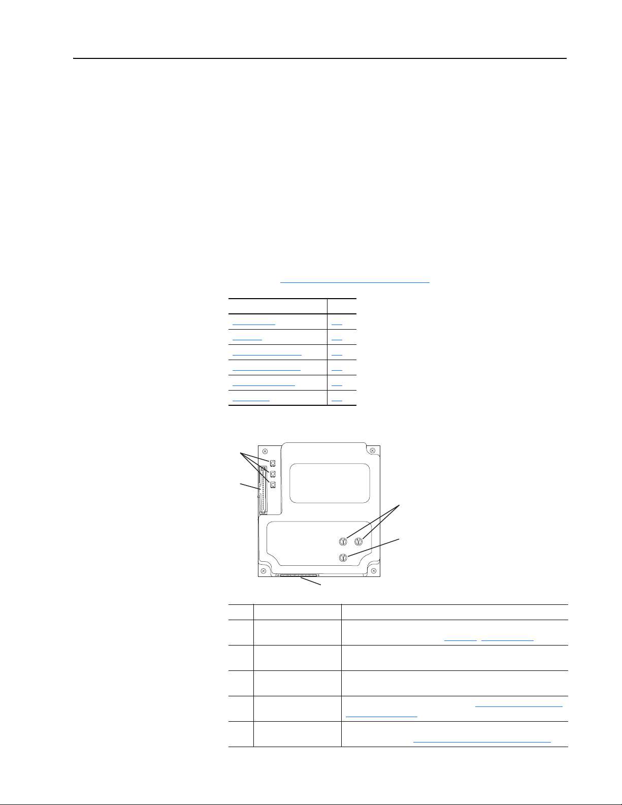
Components
➊
➋
➍
➎
➌
Item Part Description
Status Indicators Three status indicators that indicate the status of the DPI, adapter,
➊
DPI Connector A 20-pin, single-row shrouded male header. An Internal Interface
➋
DeviceNet Connector A 5-pin connector to which a 5-pin linear plug (supplied with
➌
Node Address Switches Switches to set the node address. See Setting the Node Address
➍
Data Rate Switch Switch to set the DeviceNet data rate at which the adapter
➎
and network connection. See Chapter 7
cable is connected to this connector and a connector on the drive.
adapter) can be connected for the DeviceNet network cable.
Switches on page 2-2.
communicates. See Setting the Data Rate Switch
, Troubleshooting.
on page 2-3
20-COMM-D DeviceNet Adapter User Manual
Publication 20COMM-UM002G-EN-P
Page 14

1-2 Getting Started
Features
The features of the adapter include the following:
• Typical mounting in a PowerFlex 7-Class drive. The 20-COMM-D
Series B adapter, firmware revision 2.xxx or later, can also be installed in
a DPI External Comms Kit and used with the kit’s optional I/O board.
See Chapter
(20-XCOMM-DC-BASE) for more information.
DPI External Comms Kit Compatibility
20-COMM-D Adapter Operation With
Series
A1.xxx No No
B1.xxx No No
• Captive screws to secure and ground the adapter to the drive or, when
mounted in a DPI External Comms Kit, to the kit’s metal enclosure.
• Compatibility with various configuration tools to configure the adapter
and connected host drive, including the following tools:
– PowerFlex HIM (Human Interface Module) on the drive, if available
– Connected Components Workbench software, version 1.02 or later
– DriveExplorer software, version 2.01 or later
– DriveExecutive software, version 3.01 or later
8, Using the Adapter in a DPI External Comms Kit
Firmware
Revision
2.xxx No No
2.xxx Yes Yes
DPI External Comms Kit
(20-XCOMM-DC-BASE)
Optional I/O Board
(20-XCOMM-IO-OPT1)
• Switches to set a node address and network data rate before applying
power to the PowerFlex drive, or you can disable the switches and use
adapter parameters to configure these functions.
• Status indicators that report the status of the drive communications, the
adapter, and network. They are visible when the drive cover is open or
closed.
• Parameter-configured I/O (Logic Command/Reference and up to four
pairs of Datalinks) to accommodate application requirements.
• Explicit Messaging and UCMM (Unconnected Message Manager)
support.
• Multiple data exchange methods (Polled, Cyclic, and Change of State) to
transmit data between the network and adapter.
• Master-Slave or Peer-to-Peer hierarchy that can be set up so that the
adapter and connected PowerFlex drive transmit data to and from either a
scanner or another PowerFlex drive on the network.
• User-defined fault actions to determine how the adapter and connected
drive respond to the following:
– I/O messaging communication disruptions (Comm Flt Action)
– Controllers in idle mode (Idle Flt Action)
20-COMM-D DeviceNet Adapter User Manual
Publication 20COMM-UM002G-EN-P
Page 15

Getting Started 1-3
• Faulted node recovery support. You can configure a device even when it
is faulted on the network if you have a configuration tool that uses
faulted node recovery and have set the data rate switch to ‘PGM’
(Program). The adapter then uses parameter settings for the data rate and
node address instead of switch settings.
• Access to any PowerFlex drive and its connected peripherals on the
network to which the adapter is connected.
Compatible Products
Required Equipment
At the time of publication, the adapter is compatible with the following
products:
• PowerFlex 70 drives with standard or enhanced control • PowerFlex 750-Series drives
• PowerFlex 700 drives with standard or vector control • PowerFlex Digital DC drives
• PowerFlex 700H drives • DPI External Comms Kit
• PowerFlex 700S drives with Phase I or Phase II control • SMC™ Flex smart motor controllers
• PowerFlex 700L drives with 700 vector control or 700S control • SMC-50 smart motor controllers
(1)
The 20-COMM-D adapter can be used with PowerFlex 750-Series drives, but with the following limitations/differences:
- Only drive Ports 0…6 are supported.
- Only the first 16 bits of the Logic Command and Logic Status words are used.
- Speed Reference/Feedback scaling are Hz (or RPM) x 1000 (depending on the setting of drive
parameter 300 - [Speed Units].
- For explicit messaging, only Device parameters (Class code 0x93) can be accessed (drive Por ts 0…6 only). Host
parameters (Class code 0x9F) and Parameter Object (Class code 0x0F) cannot be accessed.
Instead of using the 20-COMM-D adapter with the PowerFlex 750-Series drive, the 20-750-DNET DeviceNet option module
should be used whenever possible. Please see the PowerFlex 750-Series AC Drives Programming Manual, publication
750-PM001, for drive parameter information and the 20-750-DNET DeviceNet Option Module User Manual, publication
750COM-UM002, for network communication module information.
Some of the equipment that is required for use with the adapter is shipped
with the adapter, but some you must supply yourself.
(1)
Equipment Shipped with the Adapter
When you unpack the adapter, verify that the package includes the following:
❑ One 20-COMM-D DeviceNet adapter
❑ One 2.54 cm (1 in.) long and one 15.24 cm (6 in.) long Internal
Interface cable (only one cable is needed to connect the adapter to the
drive; for which cable to use, see Figure 2.3 on page 2-5
❑ One 5-pin linear DeviceNet plug (connected to the DeviceNet
connector on the adapter)
❑ One PowerFlex 7-Class DPI (Drive Peripheral Interface) Network
Communication Adapter Installation Instructions, publication
20COMM-IN004
TIP: When mounting the 20-COMM-D Series B adapter in a PowerFlex
750-Series drive, you must use a 20-750-20COMM or 20-750-20COMM-F1
Communication Carrier Card, publication 750COM-IN001—and the
20-COMM-D adapter must have firmware revision 2.001 or later.
20-COMM-D DeviceNet Adapter User Manual
)
Publication 20COMM-UM002G-EN-P
Page 16

1-4 Getting Started
User-Supplied Equipment
To install and configure the adapter, you must supply the following:
❑ A small flathead screwdriver
❑ DeviceNet cable – thin cable with an outside diameter of 6.9 mm (0.27
in.) is recommended
❑ Drive and adapter configuration tool, such as the following:
– PowerFlex 20-HIM-xx HIM
– RSNetWorx for DeviceNet software, version 7.00 or later
– Connected Components Workbench software, version 1.02 or later
Connected Components Workbench is the recommended
stand-alone software tool for use with PowerFlex drives. You can
obtain a free copy by:
• Internet download at http://www.ab.com/support/abdrives/
webupdate/software.html
• Requesting a DVD at http://www.ab.com/onecontact/controllers/
micro800/
Your local distributor may also have copies of the DVD available.
Connected Components Workbench software cannot be used to
configure SCANport-based drives or Bulletin 160 drives.
– DriveExplorer software, version 2.01 or later
This software tool has been discontinued and is now available as
freeware at http://www.ab.com/support/abdrives/webupdate/
software.html. There are no plans to provide future updates to this
tool and the download is being provided ‘as-is’ for users that lost
their DriveExplorer CD, or need to configure legacy products not
supported by Connected Components Workbench software.
– DriveExecutive software, version 3.01 or later
A Lite version of DriveExecutive software ships with RSLogix
5000, RSNetWorx MD, FactoryTalk AssetCentre, and
ItelliCENTER software. All other versions are purchasable items:
• 9303-4DTE01ENE Drive Executive software
• 9303-4DTS01ENE DriveTools SP Suite (includes
DriveExecutive and DriveObserver software)
• 9303-4DTE2S01ENE DriveExecutive software upgrade to
DriveTools SP Suite (adds DriveObserver software)
20-COMM-D DeviceNet Adapter User Manual
Publication 20COMM-UM002G-EN-P
DriveExecutive software updates (patches, and so forth) can be
obtained at http://www.ab.com/support/abdrives/webupdate/
software.html. It is highly recommended that you periodically check
for and install the latest update.
❑ Controller configuration tool, such as RSLogix 5, RSLogix 500, or
RSLogix 5000 software
Page 17
Getting Started 1-5
!
!
!
!
!
!
!
❑ A computer connection to the DeviceNet network via a communication
card, such as 1784-PCD, 1784-PCID, 1784-PCIDS, or 1770-KFD
Safety Precautions
Please read the following safety precautions carefully.
ATTENTION: Risk of injury or death exists. The PowerFlex
drive may contain high voltages that can cause injury or death.
Remove all power from the PowerFlex drive, and then verify
power has been discharged before installing or removing an
adapter.
ATTENTION: Risk of injury or equipment damage exists. Only
personnel familiar with drive and power products and the
associated machinery should plan or implement the installation,
start up, configuration, and subsequent maintenance of the
product using an adapter. Failure to comply may result in injury
and/or equipment damage.
ATTENTION: Risk of equipment damage exists. The adapter
contains electrostatic discharge (ESD) sensitive parts that can be
damaged if you do not follow ESD control procedures. Static
control precautions are required when handling the adapter. If
you are unfamiliar with static control procedures, see Guarding
Against Electrostatic Damage, publication 8000-4.5.2.
ATTENTION: Risk of injury or equipment damage exists. If the
adapter is transmitting control I/O to the drive, the drive may fault
when you reset the adapter. Determine how your drive will
respond before resetting an adapter.
ATTENTION: Risk of injury or equipment damage exists.
Parameters 10 - [Comm Flt Action], 11 - [Idle Flt Action], and
34 - [Peer Flt Action] let you determine the action of the adapter
and connected drive if communication is disrupted or the
controller is idle. By default, these parameters fault the drive. You
can set these parameters so that the drive continues to run,
however, precautions should be taken to verify that the settings of
these parameters do not create a risk of injury or equipment
damage. When commissioning the drive, verify that your system
responds correctly to various situations (for example, a
disconnected cable or a faulted controller).
ATTENTION: Risk of injury or equipment damage exists.
When a system is configured for the first time, there may be
unintended or incorrect machine motion. Disconnect the motor
from the machine or process during initial system testing.
ATTENTION: Risk of injury or equipment damage exists. The
examples in this publication are intended solely for purposes of
example. There are many variables and requirements with any
application. Rockwell Automation does not assume responsibility
or liability (to include intellectual property liability) for actual
use of the examples shown in this publication.
20-COMM-D DeviceNet Adapter User Manual
Publication 20COMM-UM002G-EN-P
Page 18

1-6 Getting Started
Quick Start
This section is provided to help experienced users quickly start using the
adapter. If you are unsure how to complete a step, refer to the referenced
chapter.
Step Action See
1 Review the safety precautions for the adapter. Throughout this manual
2 Verify that the PowerFlex drive is properly installed. Drive User Manual
PowerFlex 7-Class DPI
Network Communication
Adapter Installation
Instructions (publication
20COMM-IN004) and
Chapter 2
Installing the Adapter
Chapter 2
Installing the Adapter
Chapter 3
Configuring the Adapter
Chapter 4,
Configuring the I/O
Chapter 5,
Using the I/O
Chapter 6,
Using Explicit
Messaging
3 Install the adapter.
a. Verify that the PowerFlex drive is not powered.
b. Connect the adapter to the drive with the Internal Interface
cable.
c. Use the captive screws to secure and ground the adapter to
the drive.
d. Connect the adapter to the network with a DeviceNet cable.
NOTE: When installing the adapter in either of the following
products, see the listed publication for instructions:
• DPI External Comms Kit—see the 20-XCOMM-DC-BASE
Installation Instructions, publication 20COMM-IN001, supplied
with the kit.
• PowerFlex 750-Series drive—see the 20-750-20COMM and
20-750-20COMM-F1 Communication Carrier Cards
Installation Instructions, publication 750COM-IN001, supplied
with the card.
4 Apply power to the adapter.
a. Verify that the adapter is installed correctly.
The adapter receives power from the drive.
b. Apply power to the drive.
The status indicators should be green. If they flash red, there
is a problem. See Chapter 7
c. Configure and verify key drive parameters.
5 Configure the adapter for your application.
Set adapter parameters for the following functions as required by
your application:
• Node address and data rate (when Data Rate switch is set to
‘PGM’)
• I/O configuration
• Change of State, Cyclic, or Polled I/O data exchange
• Master-Slave or Peer-to-Peer hierarchy
• Fault actions
6 Configure the controller to communicate with the adapter.
Use configuration tools, such as RSNetWorx for DeviceNet
software and RSLogix software, to configure the master on the
network to recognize the adapter and drive.
7 Create a ladder logic program.
Use a controller configuration tool, such as RSLogix software, to
create a ladder logic program that enables you to do the
following:
• Control the connected drive, via the adapter, by using I/O.
• Monitor or configure the drive using explicit messages.
, Troubleshooting.
,
,
,
20-COMM-D DeviceNet Adapter User Manual
Publication 20COMM-UM002G-EN-P
Page 19
Chapter 2
!
Installing the Adapter
This chapter provides instructions for installing the adapter in a PowerFlex
7-Class drive. The 20-COMM-D Series B adapter, firmware revision 2.xxx
or later, can also be installed in a DPI External Comms Kit. In this case, see
Chapter 8
publication 20COMM-IN001, supplied with the kit.
Topic Page
Preparing for an Installation
Setting the Node Address Switches 2-2
Setting the Data Rate Switch 2-3
Connecting the Adapter to the Drive 2-4
Connecting the Adapter to the Network 2-7
Applying Power 2-8
Commissioning the Adapter 2-10
or the 20-XCOMM-DC-BASE Installation Instructions,
2-1
Preparing for an Installation
Before installing the adapter, do the following:
• Read the DeviceNet Media Design and Installation Guide, publication
DNET-UM072.
• Read the DeviceNet Starter Kit User Manual, publication
DNET-UM003.
• Verify that you have all required equipment. See Required Equipment
page 1-3.
ATTENTION: Risk of equipment damage exists. The adapter
contains electrostatic discharge (ESD) sensitive parts that can be
damaged if you do not follow ESD control procedures. Static
control precautions are required when handling the adapter. If you
are unfamiliar with static control procedures, see Guarding
Against Electrostatic Damage, publication 8000-4.5.2.
on
20-COMM-D DeviceNet Adapter User Manual
Publication 20COMM-UM002G-EN-P
Page 20
2-2 Installing the Adapter
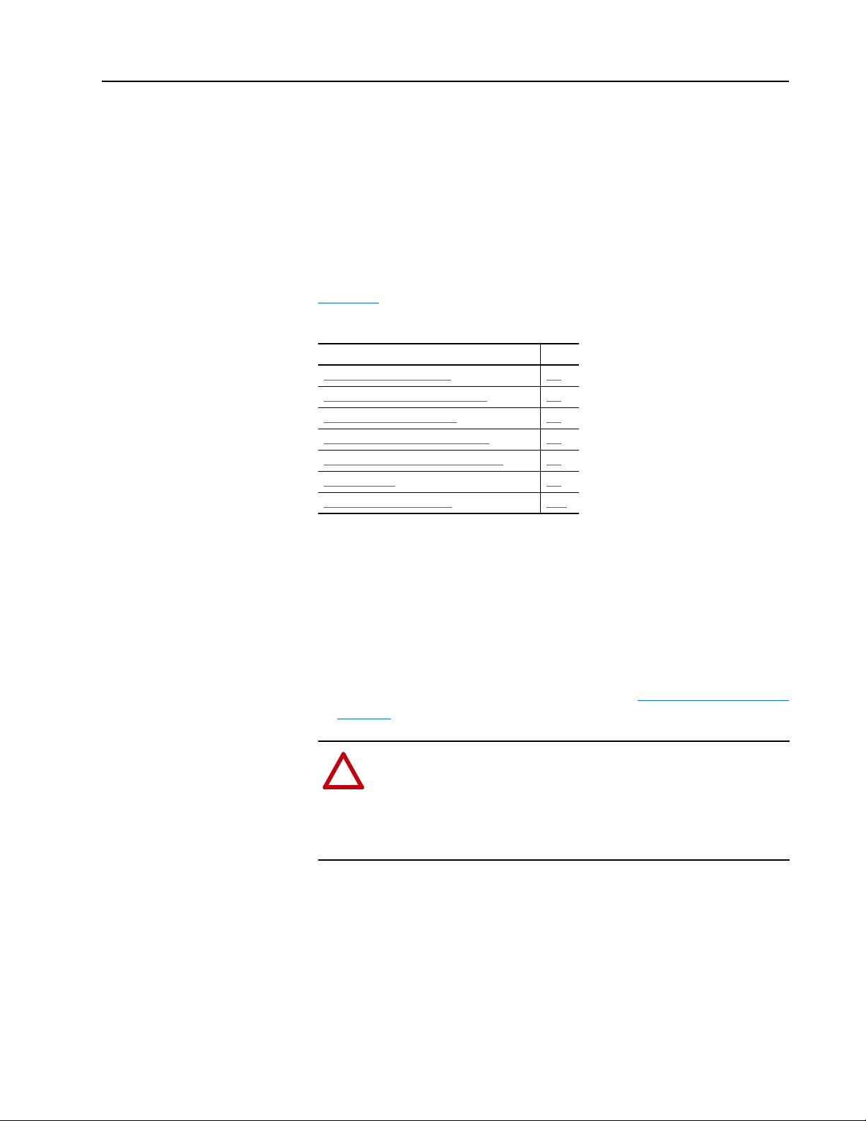
Setting the Node Address Switches
Set the adapter Node Address switches (Figure 2.1) by rotating the switches
to the desired value for each digit.
Important: Each node on the DeviceNet network must have a unique
address. Set the node address before power is applied because
the adapter uses the node address it detects when it first
receives power. To change a node address, you must set the new
value and then remove and reapply power to (or reset) the
adapter.
Figure 2.1 Setting Adapter Node Address Switches
2
3
1
0
9
8
4
5
6
7
Te ns
Digit
2
3
1
0
9
8
4
5
6
7
Ones
Digit
Setting Description
0…63 The node address used by the adapter if the Node Address switches are enabled.
The default switch setting is 63. Node address 63 is also the default address used by all
uncommissioned devices. We recommend that you do not use this address as the final
adapter address.
Important: If the Data Rate switch is set to ‘PGM’ (Program), the adapter uses the value
stored in Parameter 03 - [DN Addr Cfg] for the node address. See Setting the Node
Address on page 3-3.
64…99 Do not use. The adapter will not recognize these addresses.
The Node Address switch settings can be verified by viewing Parameter 04
- [DN Addr Act] or Diagnostic Device Item number 30 (page 7-5
of the following drive configuration tools:
• PowerFlex HIM
• Connected Components Workbench software, version 1.02 or later
• DriveExplorer software, version 2.01 or later
• DriveExecutive software, version 3.01 or later
) with any
20-COMM-D DeviceNet Adapter User Manual
Publication 20COMM-UM002G-EN-P
Page 21
Installing the Adapter 2-3
125K
250K
500K
PGM
AUTO
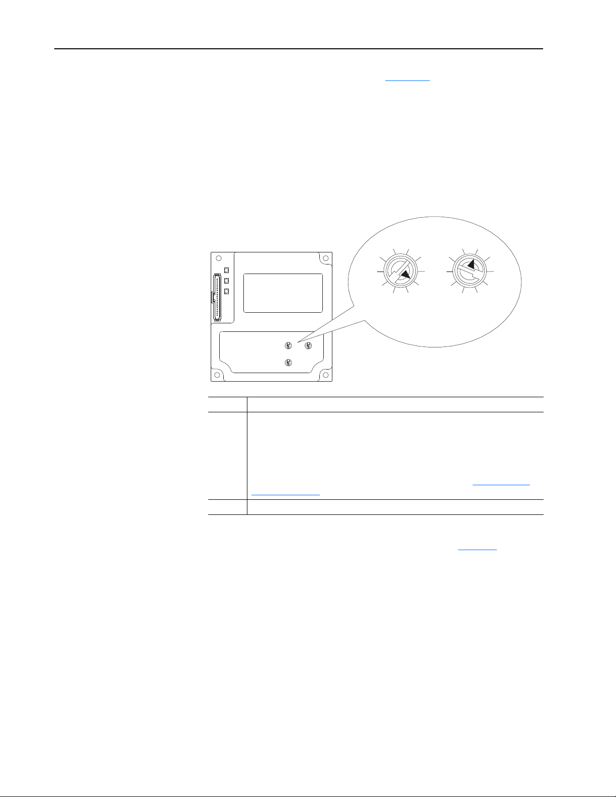
Setting the Data Rate Switch
Set the adapter Data Rate switch (Figure 2.2) by rotating the switch to the
desired setting.
Figure 2.2 Setting Adapter Data Rate Switch
Setting Description
Auto Sets the adapter to the data rate used by other network devices. Another
device on the network must be set to a data rate.
125K, 250K, 500K Sets the adapter to the respective data rate.
PGM (default) The adapter uses the value stored in Parameter 05 - [DN Rate Cfg] for the
data rate. See Setting the Data Rate
value stored in Parameter 03 - [DN Addr Cfg] for the node address. See
Setting the Node Address on page 3-3.
The Data Rate switch setting can be verified by viewing Parameter 06 [DN Rate Act] or Diagnostic Device Item number 29 (page 7-5
of the following drive configuration tools:
on page 3-3. Also, the adapter uses the
) with any
• PowerFlex HIM
• Connected Components Workbench software, version 1.02 or later
• DriveExplorer software, version 2.01 or later
• DriveExecutive software, version 3.01 or later
20-COMM-D DeviceNet Adapter User Manual
Publication 20COMM-UM002G-EN-P
Page 22

2-4 Installing the Adapter
!
Connecting the Adapter to the Drive
ATTENTION: Risk of injury or death exists. The PowerFlex
drive may contain high voltages that can cause injury or death.
Remove power from the drive, and then verify power has been
discharged before installing or removing the adapter.
1. Remove power from the drive.
2. Use static control precautions.
3. Remove or open the drive cover.
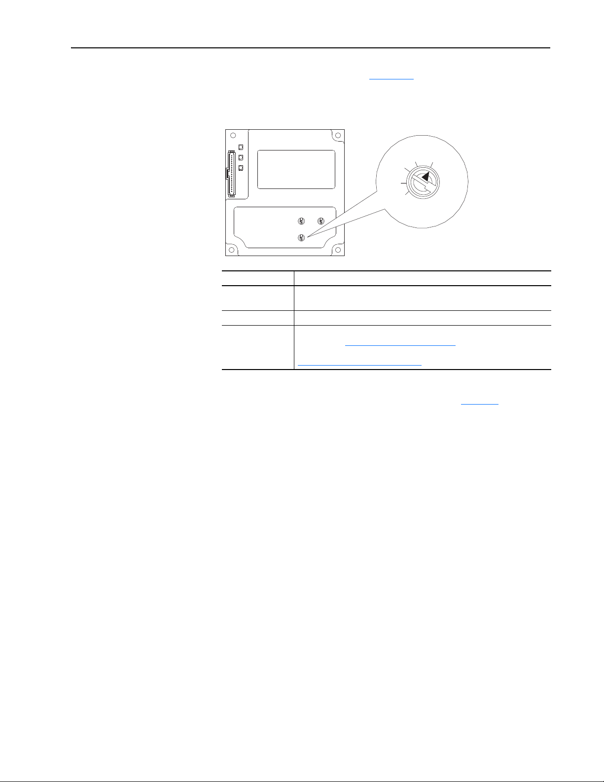
4. Connect the Internal Interface cable to the DPI port on the drive and
then to the DPI connector on the adapter (see Figure 2.3
5. Secure and ground the adapter to the drive (see Figure 2.4
following:
– On a PowerFlex 70 drive, fold the Internal Interface cable behind the
adapter and mount the adapter on the drive using the four captive
screws.
– On a PowerFlex 700, PowerFlex 700H or PowerFlex 700S drive,
mount the adapter on the drive using the four captive screws.
Important: Tighten all screws to properly ground the adapter.
Recommended torque is 0.9 N•m (8.0 lb•in).
).
) by doing the
20-COMM-D DeviceNet Adapter User Manual
Publication 20COMM-UM002G-EN-P
Page 23
20-COMM-D Adapter
PowerFlex 700 Frames 0 and 1
PowerFlex 700S Frames 0 and 1
PowerFlex 70 - All Frames
PowerFlex 700 Frames 2 and Larger
PowerFlex 700S Frames 2 through 6
HIM panel opens to
allow access to DPI
interface. To open
panel, remove screws
on left side of HIM
panel and swing open.
PowerFlex 700H Frames 9 and Larger
PowerFlex 700S Frames 9 and Larger
Installing the Adapter 2-5
Figure 2.3 DPI Ports and Internal Interface Cables
➊
➋
➌
➍
Item Description
15.24 cm (6 in.) Internal Interface cable
➊
DPI Connector
➋
DeviceNet cable
➌
2.54 cm (1 in.) Internal Interface cable
➍
X2
X1
➍
20-COMM-D DeviceNet Adapter User Manual
Publication 20COMM-UM002G-EN-P
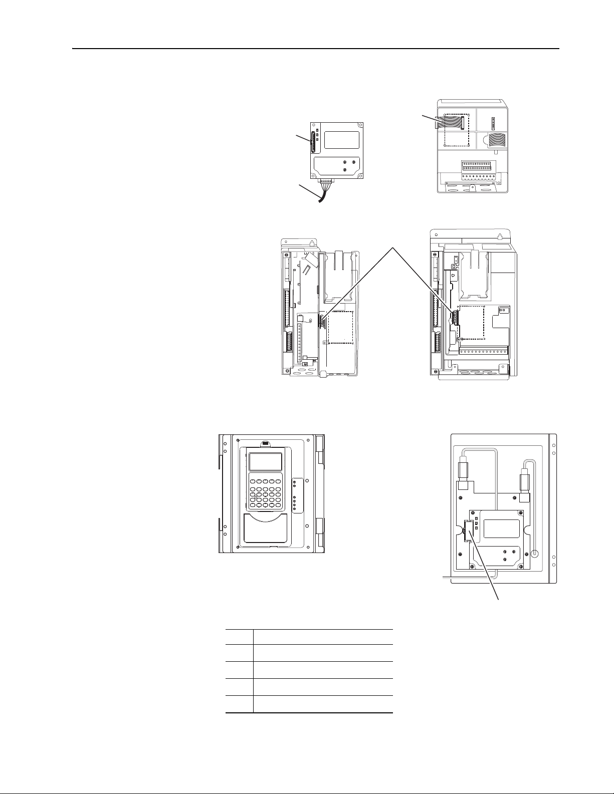
Page 24

2-6 Installing the Adapter
Drive
Adapter
Internal Interface Cable
folded behind the adapter
and in front of the drive.
PowerFlex 70 - All Frame Sizes
(Adapter mounts in drive.)
Verify metal ground tab is bent 90° and
is under the adapter before tightening
screw. After tightening the screw, verify
continuity exists between the head of
the screw and drive ground.
Ground Tab Detail
PowerFlex 700 Frames 0 and 1
PowerFlex 700S Frames 0 and 1
(Adapter mounts on door.)
PowerFlex 700 Frames 2 and Larger
PowerFlex 700S Frames 2 through 6
(Adapter mounts in drive.)
0.9 N•m
(8.0 lb•in)
4 Places
Verify metal ground tab is bent 90° and
is under the adapter before tightening
screw. After tightening the screw, verify
continuity exists between the head of
the screw and drive ground.
PowerFlex 700H Frames 9 and Larger
PowerFlex 700S Frames 9 and Larger
(Adapter mounts behind HIM panel.)
Ground Tab Detail
0.9 N•m
(8.0 lb•in)
4 Places
0.9 N•m
(8.0 lb•in)
4 Places
Figure 2.4 Mounting and Grounding the Adapter
X2
X1
20-COMM-D DeviceNet Adapter User Manual
Publication 20COMM-UM002G-EN-P
NOTE: When installing the adapter in a PowerFlex 750-Series drive, see
the 20-750-20COMM and 20-750-20COMM-F1 Communication Carrier
Cards Installation Instructions, publication 750COM-IN001, supplied with
the card.
Page 25
Installing the Adapter 2-7
!
5
4
3
2
1
Red
White
Bare
Blue
Black
Connecting the Adapter to the Network
ATTENTION: Risk of injury or death exists. The PowerFlex
drive may contain high voltages that can cause injury or death.
Remove power from the drive, and then verify power has been
discharged before installing or removing the adapter.
1. Remove power from the network and drive.
2. Use static control precautions.
3. Connect one end of a DeviceNet cable to the network.
We recommend DeviceNet Thin cable with an outside diameter of 6.9
mm (0.27 in.).
Important: Maximum cable length depends on the data rate. For
details, see Data Rate
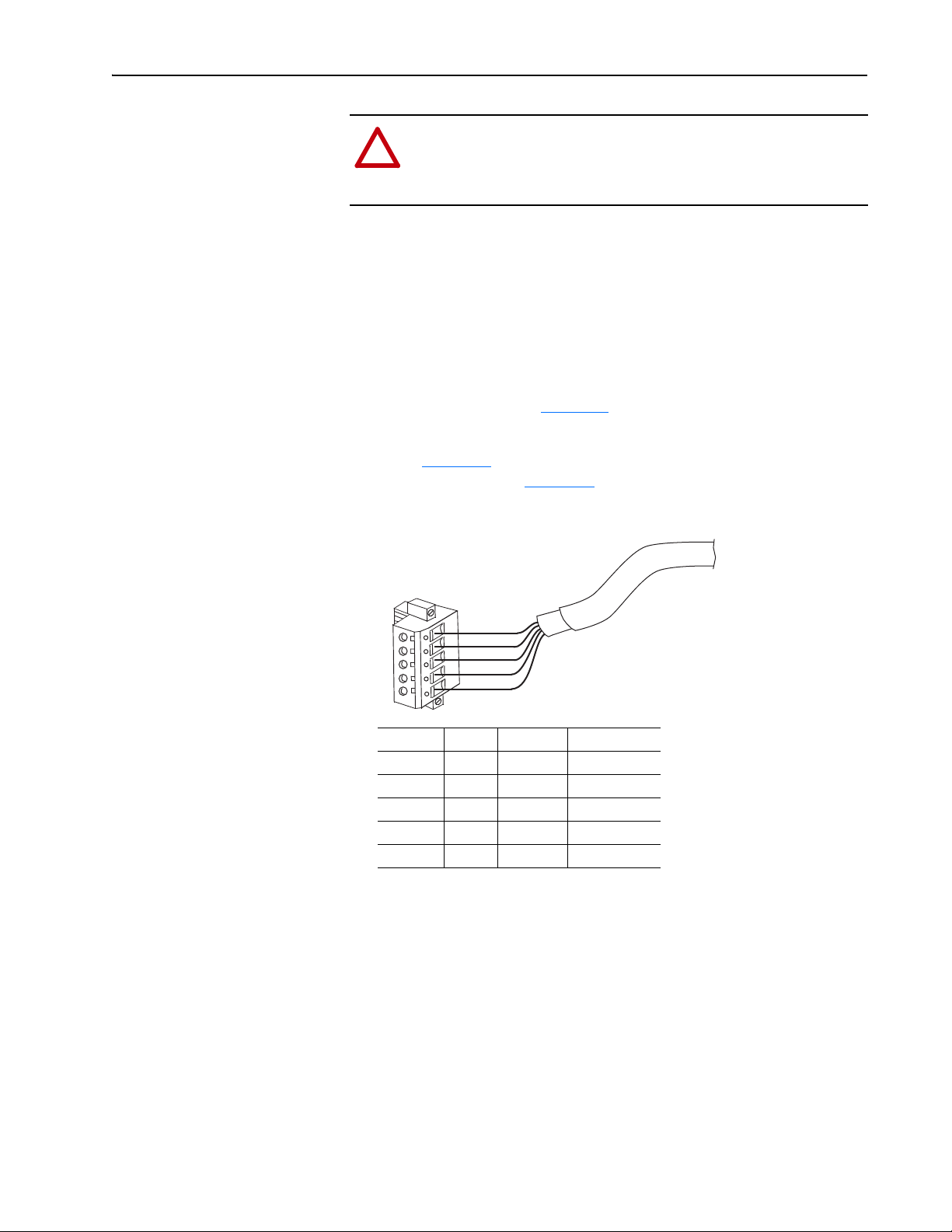
4. Route the other end of the DeviceNet cable through the bottom of the
drive (Figure 2.4
with the adapter. See Figure 2.5
Figure 2.5 Connecting the 5-Pin Linear Plug to the DeviceNet Cable
), and connect its wires to the 5-pin linear plug shipped
in the Glossary.
for wiring details.
Terminal Color Signal Function
5 Red V+ Power Supply
4 White CAN_H Signal High
3 Bare SHIELD Shield
2 Blue CAN_L Signal Low
1BlackV–Common
5. Insert the DeviceNet cable plug into the mating adapter connector, and
secure it with the two screws.
6. Verify that the colors of the wires on the plug match the color codes on
the connector.
20-COMM-D DeviceNet Adapter User Manual
Publication 20COMM-UM002G-EN-P
Page 26
2-8 Installing the Adapter
!
Applying Power
ATTENTION: Risk of equipment damage, injury, or death
exists. Unpredictable operation may occur if you fail to verify
that parameter settings are compatible with your application.
Verify that settings are compatible with your application before
applying power to the drive.
Install the drive cover or close the drive door, and apply power to the drive.
The adapter receives its power from the connected drive. When you apply
power to the adapter for the first time, its topmost ‘PORT’ status indicator
should be steady green or flashing green after an initialization. If it is red,
there is a problem. See Chapter 7
Start-Up Status Indications
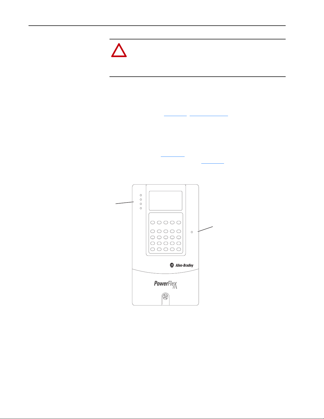
Status indicators for the drive and communication adapter can be viewed on
the front of the drive (Figure 2.6
start-up status indications are shown in Table 2 .A
Figure 2.6 Drive and Adapter Status Indicators (location on drive may vary)
, Troubleshooting.
) after power has been applied. Possible
.
PORT
MOD
➋
NET A
NET B
➊
STS
20-COMM-D DeviceNet Adapter User Manual
Publication 20COMM-UM002G-EN-P
Page 27

Installing the Adapter 2-9
Table 2.A Drive and Adapter Start-Up Status Indications
Item Name Color State Description
Drive STS Indicator
STS
➊
(Status)
PORT Green Flashing Normal operation. The adapter is establishing an I/O
➋
MOD Green Flashing Normal operation. The adapter is operating but is not
NET A Green Flashing Normal operation. The adapter is properly connected
NET B — — Not used by DeviceNet adapter.
Green Flashing Drive ready but not running, and no faults are present.
Steady Drive running, no faults are present.
Yellow Flashing,
drive stopped
Flashing,
drive running
Steady,
drive running
Red Flashing A fault has occurred.
Steady A non-resettable fault has occurred.
Adapter Status Indicators
Steady Normal operation. The adapter is properly connected
Steady Normal operation. The adapter is operating and
Steady Normal operation. The adapter is properly connected
An inhibit condition exists – the drive cannot be
started. Check drive Parameter 214 - [Start Inhibits].
An intermittent type 1 alarm condition is occurring.
Check drive Parameter 211 - [Drive Alarm 1].
A continuous type 1 alarm condition exists. Check
drive Parameter 211 - [Drive Alarm 1].
connection to the drive. It will turn steady green or red.
and communicating with the drive.
transferring I/O data to a controller.
transferring I/O data to a controller.
but does not have an I/O connection.
and communicating on the network.
For more details on status indicator operation, see page 7-2 and page 7-3.
Configuring and Verifying Key Drive Parameters
The PowerFlex 7-Class drive can be separately configured for the control
and Reference functions in various combinations. For example, you could
set the drive to have its control come from a peripheral or terminal block
with the Reference coming from the network. Or you could set the drive to
have its control come from the network with the Reference coming from
another peripheral or terminal block. Or you could set the drive to have both
its control and Reference come from the network.
The following steps in this section assume that the drive will receive the
Logic Command and Reference from the network.
1. Use drive Parameter 090 - [Speed Ref A Sel] to set the drive speed
Reference to ‘22’ (DPI Port 5).
2. If hard-wired discrete digital inputs are not used to control the drive,
verify that unused digital input drive Parameters 361 - [Dig In1 Sel] and
366 - [Dig In2 Sel] are set to ‘0’ (Not Used).
20-COMM-D DeviceNet Adapter User Manual
Publication 20COMM-UM002G-EN-P
Page 28

2-10 Installing the Adapter
3. Verify that drive Parameter 213 - [Speed Ref Source] is reporting that
the source of the Reference to the drive is ‘22’ (DPI Port 5).
This ensures that any Reference commanded from the network can be
monitored by using drive Parameter 002 - [Commanded Speed]. If a
problem occurs, this verification step provides the diagnostic capability
to determine whether the drive/adapter or the network is the cause.
TIP: For PowerFlex 750-Series drives, use drive Parameter 545 [Speed Ref A Sel] to set the drive speed Reference:
a. Set the Port field to ‘Port 0 - PowerFlex 75x’.
b. Set the Parameter field to point to the port in which the
20-COMM-D adapter/20-750-20COMM Communication Carrier
Card are installed (for example, ‘876 - Port 6 Reference’).
The number ‘876’ in the Parameter field of the example is the
parameter in the drive that points to the port.
Commissioning the Adapter
To commission the adapter, you must set a unique node address on the
network. See Setting the Node Address
details about node addresses.
Important: New settings for some adapter parameters are recognized only
when power is applied to the adapter or it is reset. After you
change parameter settings, cycle power or reset the adapter.
on page 3-3, and the Glossary for
20-COMM-D DeviceNet Adapter User Manual
Publication 20COMM-UM002G-EN-P
Page 29
Chapter 3
Configuring the Adapter
This chapter provides instructions and information for setting the
parameters to configure the adapter.
Topic Page
Configuration Tools
Using the PowerFlex 7-Class HIM to Access Parameters 3-2
Setting the Node Address 3-3
Setting the Data Rate 3-3
Setting the I/O Configuration 3-4
Selecting Master-Slave or Peer-to-Peer Hierarchy 3-5
Selecting COS, Cyclic or Polled I/O 3-10
Setting a Fault Action 3-11
Resetting the Adapter 3-12
Viewing the Adapter Status Using Parameters 3-13
Updating the Adapter Firmware 3-14
3-1
Configuration Tools
For a list of parameters, see Appendix
definitions of terms in this chapter, see the Glossary
The adapter stores parameters and other information in its own nonvolatile
storage (NVS) memory. You must, therefore, access the adapter to view and
edit its parameters. The following tools can be used to access the adapter
parameters.
Tool See
PowerFlex 7-Class HIM page 3-2
Connected Components Workbench
software, version 1.02 or later
DriveExplorer software,
version 2.01 or later
DriveExecutive software,
version 3.01 or later
B, Adapter Parameters. For
.
http://www.ab.com/support/abdrives/webupdate/
software.html, or online help (installed with the software)
http://www.ab.com/drives/driveexplorer
DriveExplorer online help (installed with the software)
http://www.ab.com/drives/drivetools
DriveExecutive online help (installed with the software)
, or
, or
20-COMM-D DeviceNet Adapter User Manual
Publication 20COMM-UM002G-EN-P
Page 30
3-2 Configuring the Adapter
ALT
Sel
F-> Stopped Auto
0.00 Hz
Main Menu:
Diagnostics
Parameter
Device Select
Por t 5 Device
20-COMM-D
Main Menu:
Diagnostics
Parameter
Device Select
Using the PowerFlex 7-Class HIM to Access Parameters
If your drive has either an LED or LCD HIM (Human Interface Module), it
can be used to access parameters in the adapter as shown below. We
recommend that you read through the steps for your HIM before performing
the sequence. For additional information, see the drive documentation or the
PowerFlex 7-Class HIM Quick Reference, publication 20HIM-QR001.
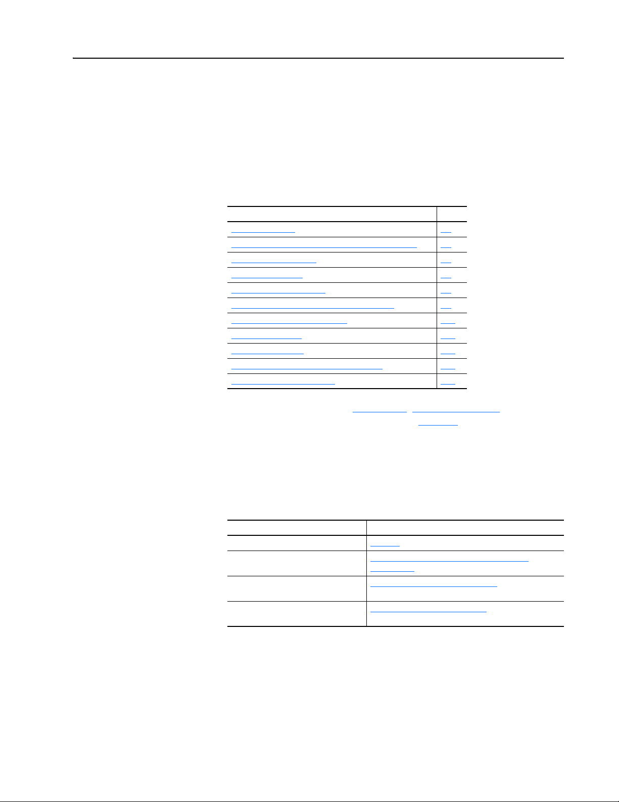
Using an LED HIM
Step Example Screens
1. Press the key and then the Device (Sel) key to
display the Device Screen.
2. Press the or key to scroll to the adapter.
Letters represent files in the drive, and numbers represent
ports. The adapter is usually connected to port 5.
3. Press the (Enter) key to enter your selection.
A parameter database is constructed, and then the first
parameter is displayed.
4. Edit the parameters using the same techniques that you use
to edit drive parameters.
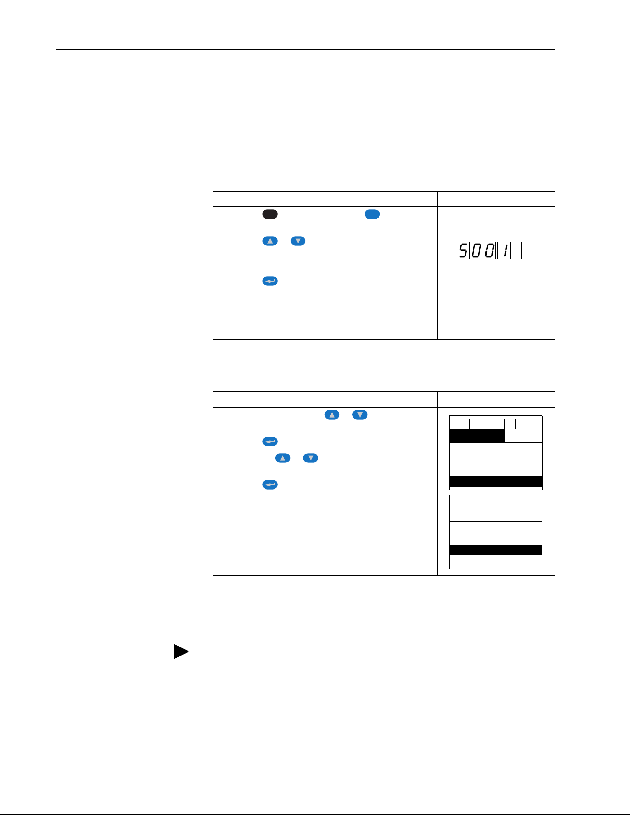
Using an LCD HIM
Step Example Screens
1. In the main menu, press the or key to scroll to
Device Select.
2. Press the (Enter) key to enter your selection.
3. Press the the or key to scroll to the adapter
(20-COMM-D).
4. Press the (Enter) key to select the adapter.
A parameter database is constructed, and then the main
menu for the adapter is displayed.
5. Edit the parameters using the same techniques that you use
to edit drive parameters.
20-COMM-D DeviceNet Adapter User Manual
Publication 20COMM-UM002G-EN-P
NOTE: All configuration procedures throughout this chapter use the
PowerFlex 7-Class LCD HIM to access parameters in the adapter and show
example LCD HIM screens.
TIP: When using a PowerFlex 20-HIM-A6 or 20-HIM-C6S HIM, see its
User Manual, publication 20-HIM-UM001.
Page 31

Configuring the Adapter 3-3
Por t 5 Device
20-COMM-D
Parameter #: 03
DN Addr Cfg
63
0 <> 63
Default = 63
Value Da ta Rat e
0 125 kbps
1 250 kbps
2 500 kbps
3 Autobaud (default)
Por t 5 Device
20-COMM-D
Parameter #: 05
DN Rate Cfg
3
Autodetect
Setting the Node Address
Setting the Data Rate
If the adapter Data Rate switch (Figure 2.2) is set to ‘PGM’ (Program), the
value of Parameter 03 - [DN Addr Cfg] determines the node address. We
recommend not to use the default node address 63 because all new devices
on the network use this address as the default address. Also, node address
63 is used for Automatic Device Recovery (ADR).
1. Set the value of Parameter 03 - [DN Addr Cfg] to a unique node
address.
2. Reset the adapter (see Resetting the Adapter
When the node address is correctly configured and the adapter is connected
to an operational network, the NET A status indicator should be steady
green or flashing green.
If the adapter Data Rate switch (Figure 2.2) is set to ‘PGM’ (Program), the
value of Parameter 05 - [DN Rate Cfg] determines the data rate. The
default Autobaud setting will detect the data rate used on the network if
another device is setting the data rate. Your application may require a
different setting.
on page 3-12).
1. Set the value of Parameter 05 - [DN Rate Cfg] to the data rate at
which your network is operating.
2. Reset the adapter (see Resetting the Adapter
on page 3-12).
20-COMM-D DeviceNet Adapter User Manual
Publication 20COMM-UM002G-EN-P
Page 32

3-4 Configuring the Adapter
Bit Description
0 Logic Command/Reference (Default)
1 Datalink A
2 Datalink B
3 Datalink C
4 Datalink D
5…15 Not Used
Por t 5 Device
20-COMM-D
Parameter #: 13
DPI I/O Cfg
xxxxxxxxxxx0000
1
Cmd/Ref b00
Setting the I/O Configuration
The I/O configuration determines the data that is sent to and from the drive.
Logic Command/Status, Reference/Feedback, and Datalinks may be
enabled or disabled. (Datalinks allow you to read/write directly to
parameters in the drive using implicit I/O.) A ‘1’ enables the I/O and a ‘0’
disables the I/O.
1. Set the bits in Parameter 13 - [DPI I/O Cfg].
Bit 0 is the right-most bit. It is highlighted above and equals ‘1’.
2. If a controller is used to control the drive, set adapter Parameters 25 [M-S Input] and 26 - [M-S Output] for Master-Slave Hierarchy.
For details, see Setting a Master-Slave Hierarchy (Scanner-to-Drive
Communication) on page 3-5.
3. If Logic Command/Reference is enabled, configure the parameters in
the drive to accept the Logic Command and Reference from the adapter.
For example, set Parameter 90 - [Speed Ref A Sel] in a PowerFlex 70 or
700 drive to ‘22’ (DPI Port 5) so that the drive uses the Reference from
the adapter. Also, verify that the mask parameters (for example,
Parameter 276 - [Logic Mask]) in the drive are configured to receive the
desired logic from the adapter. See the documentation for your drive for
details.
4. If you enabled one or more Datalinks, configure parameters in the drive
to determine the source and destination of data in the Datalinks.
When using Datalinks, up to 8 drive [Data In xx] parameters
(300…307) and/ or up to 8 [Data Out xx] parameters (310…317) must
be assigned to point to the appropriate drive parameters for your
application. See Chapter 4
5. Reset the adapter (see Resetting the Adapter
The adapter is ready to receive I/O. You must now configure the adapter to
receive I/O from a master or peer device. See Selecting Master-Slave or
Peer-to-Peer Hierarchy on page 3-5. If you select a Master-Slave hierarchy,
you must also configure the master to communicate with the adapter. See
Chapter
4, Configuring the I/O.
for an example.
on page 3-12).
20-COMM-D DeviceNet Adapter User Manual
Publication 20COMM-UM002G-EN-P
Page 33

Configuring the Adapter 3-5
Bit Description
0 Logic Command/Reference (Default)
1 Datalink A Input
2 Datalink B Input
3 Datalink C Input
4 Datalink D Input
5…15 Not Used
Por t 5 Device
20-COMM-D
Parameter #: 25
M-S Input
xxxxxxxxxxx0000
1
Cmd/Ref b00
Bit Description
0 Status/Feedback (Default)
1 Datalink A Output
2 Datalink B Output
3 Datalink C Output
4 Datalink D Output
5…15 Not Used
Por t 5 Device
20-COMM-D
Parameter #: 26
M-S Output
xxxxxxxxxxx00 0 0
1
Status/Fdbk b00
Selecting Master-Slave or Peer-to-Peer Hierarchy
A hierarchy determines the type of device with which the adapter exchanges
data. In a Master-Slave hierarchy, the adapter exchanges data with a master,
such as a scanner (1756-DNB, 1771-SDN, 1747-SDN, and so forth). In a
Peer-to-Peer hierarchy, the adapter exchanges data with one or more
DeviceNet adapters connected to other drives. (The drives must have
compatible Logic Command/Status words.)
Setting a Master-Slave Hierarchy (Scanner-to-Drive Communication)
1. Enable the desired I/O in Parameter 13 - [DPI I/O Cfg].
See Setting the I/O Configuration
2. Set the bits in Parameter 25 - [M-S Input].
This parameter determines the data received from the master by the
drive. A ‘1’ enables the I/O and a ‘0’ disables the I/O.
on page 3-4.
Bit 0 is the right-most bit. It is highlighted above and equals ‘1’.
3. Set the bits in Parameter 26 - [M-S Output].
This parameter determines the data transmitted from the drive to the
scanner. A ‘1’ enables the I/O and a ‘0’ disables the I/O.
Bit 0 is the right-most bit. It is highlighted above and equals ‘1’.
4. Reset the adapter (see Resetting the Adapter
The adapter is ready to receive I/O from the master (that is, scanner). You
must now configure the scanner to recognize and transmit I/O to the adapter.
See Chapter
4, Configuring the I/O.
on page 3-12).
20-COMM-D DeviceNet Adapter User Manual
Publication 20COMM-UM002G-EN-P
Page 34

3-6 Configuring the Adapter
Value Setting
0 Off (Default)
1On
Por t 5 Device
20-COMM-D
Parameter #: 41
Peer Out Enable
0
Off
Por t 5 Device
20-COMM-D
Parameter #: 39
Peer A Output
1
Cmd/Ref
Value Description
0 Off (Default)
1 Logic Command/Reference
2…5 Datalink A, B, C, or D Input
6…9 Datalink A, B, C, or D Output
Por t 5 Device
20-COMM-D
Parameter #: 40
Peer B Output
2
DL A Input
Value Description
0 Off (Default)
1 Logic Command/Reference
2…5 Datalink A, B, C, or D Input
6…9 Datalink A, B, C, or D Output
Setting the Adapter to Transmit Peer-to-Peer Data (Drive-to-Drive Communication)
1. Verify that Parameter 41 - [Peer Out Enable] is set to ‘0’ (Off).
This parameter must be Off while you configure peer output parameters.
2. Set Parameter 39 - [Peer A Output] to select the source of the data to
output to the network.
20-COMM-D DeviceNet Adapter User Manual
Publication 20COMM-UM002G-EN-P
Important: When transmitting a 32-bit Reference or 32-bit Datalink,
3. If desired, set Parameter 40 - [Peer B Output] to select an additional
source of the data to output to the network.
4. Set Parameters 42 - [Peer Out Time] and 43 - [Peer Out Skip] to
establish the minimum and maximum intervals between Peer messages.
Because the adapter transmits Peer messages when a change-of-state
condition occurs, minimum and maximum intervals are required.
– The minimum interval ensures that the adapter does not transmit
messages on the network too often, thus minimizing network traffic.
It is set using Parameter 42 - [Peer Out Time].
– The maximum interval ensures that the adapter transmits messages
often enough so that the receiving adapters can receive recent data
and verify that communication is working or, if communication is
not working, can timeout. The maximum interval is the value of
Parameter 42 - [Peer Out Time] multiplied by the value of
Parameter 43 - [Peer Out Skip].
only Peer A Output will be available. Peer B Output cannot
be used.
Page 35

Configuring the Adapter 3-7
Por t 5 Device
20-COMM-D
Parameter #: 42
Peer Out Time
2.00 s
0 <> 10.00
Por t 5 Device
20-COMM-D
Parameter #: 43
Peer Out Skip
2
1 <>16
Default = 10.00 s Default = 1
Value Setting
0 Off (Default)
1On
Por t 5 Device
20-COMM-D
Parameter #: 37
Peer Inp Enable
0
Off
Por t 5 Device
20-COMM-D
Parameter #: 35
Peer Node to Inp
0
0 <> 63
Default = 0
In this example, the minimum interval is set to 2.00 seconds (Parameter
42 - [Peer Out Time]), and the maximum interval is set to 4.00 seconds
(2.00 x ‘2’ setting of Parameter 43 - [Peer Out Skip]).
5. Set Parameter 41 - [Peer Out Enable] to ‘1’ (On).
The adapter will transmit the data selected in Parameters 39 - [Peer A
Output] and 40 - [Peer B Output] to the network. Another adapter
must be configured to receive the peer I/O data.
Setting the Adapter to Receive Peer-to-Peer Data
Important: The device receiving peer data must match the data sizes of the
sending device. For example, if the sending device uses a 16-bit
Reference, the receiving device must also use a 16-bit
Reference. Datalinks, if used, must also be the same size.
1. Verify that Parameter 37 - [Peer Inp Enable] is set to ‘0’ (Off).
This parameter must be Off while you configure the peer input
parameters.
2. Set Parameter 35 - [Peer Node to Inp] to the address of the node from
which you want to receive data.
Valid nodes must have 20-COMM-D adapters connected to drives with
compatible Logic Command/Status words.
20-COMM-D DeviceNet Adapter User Manual
Publication 20COMM-UM002G-EN-P
Page 36

3-8 Configuring the Adapter
!
Por t 5 Device
20-COMM-D
Parameter #: 30
Peer A Input
1
Cmd/Ref
Value Description
0 Off (Default)
1 Logic Command/Reference
2…5 Datalink A, B, C, or D Input
Por t 5 Device
20-COMM-D
Parameter #: 31
Peer B Input
2
DL A Input
Value Description
0 Off (Default)
1 Logic Command/Reference
2…5 Datalink A, B, C, or D Input
Value Description
0 Ignore this command bit. (Default)
1 Use this command bit.
Por t 5 Device
20-COMM-D
Parameter #: 32
Peer Cmd Mask
000000000000000
0
Bit 0 B00
3. Set Parameter 30 - [Peer A Input] to select the destination of the data
that is input to the drive as Peer A.
Important: When receiving a 32-bit Reference or 32-bit Datalink, only
Peer A Input will be available. Peer B Input cannot be used.
4. If desired, set Parameter 31 - [Peer B Input] to select the destination
of the data to input to the drive as Peer B.
5. If the adapter receives a Logic Command, set the bits in Parameter 32 [Peer Cmd Mask] that the drive should use.
The bit definitions for the Logic Command word will depend on the
drive to which the adapter is connected. See Appendix
documentation.
Important: If the adapter receives a Logic Command from both a
Master device and a Peer device, each command bit must
have only one source. The source of command bits set to
‘0’ will be the Master device. The source of command bits
set to ‘1’ will be the Peer device.
6. Reset the adapter (see Resetting the Adapter
changes to Parameter 32 - [Peer Cmd Mask] take effect.
7. If the adapter is receiving a Reference, it can be scaled using
Parameter 33 - [Peer Ref Adjust] to the desired scaling factor
between 0.00…199.99%.
on page 3-12) so that
D or the drive
20-COMM-D DeviceNet Adapter User Manual
Publication 20COMM-UM002G-EN-P
ATTENTION: To guard against equipment damage and/or
personal injury, note that changes to adapter Parameter 33 -
[Peer Ref Adjust] take effect immediately. A drive receiving its
Reference from peer I/O will receive the newly scaled Reference,
resulting in a change of speed.
Page 37

Configuring the Adapter 3-9
!
Por t 5 Device
20-COMM-D
Parameter #: 33
Peer Ref Adjust
0.00 %
0.00 <> 199.99
Default = 0.00%
Por t 5 Device
20-COMM-D
Parameter #: 36
Peer Inp Timeout
5.00 s
0.01 <> 180.00
Default = 10.00 s
Por t 5 Device
20-COMM-D
Parameter #: 34
Peer Flt Action
0
Fault
Value Description
0 Fault (Default)
1Stop
2Zero Data
3 Hold Last
4 Send Flt Cfg
8. Set Parameter 36 - [Peer Inp Timeout] to the maximum amount of
time the adapter will wait for a message before timing out.
Important: This value must be greater than the product of Parameter
42 - [Peer Out Time] multiplied by Parameter 43 - [Peer
Out Skip] in the adapter from which you are receiving I/O.
For example, if the value of Parameter 42 - [Peer Out Time] is 2.00
seconds and the value of Parameter 43 - [Peer Out Skip] is 2, then
Parameter 36 - [Peer Inp Timeout] needs to have a value greater than
4.00, such as 5.00 in the example below.
9. Set Parameter 34 - [Peer Flt Action] to the action that the adapter will
take if it times out.
ATTENTION: Risk of injury or equipment damage exists.
Parameter 34 - [Peer Flt Action] lets you determine the action
of the adapter and connected drive if peer communication is
disrupted. By default, this parameter faults the drive. You can set
this parameter so that the drive continues to run, however,
precautions should be taken to verify that the setting of this
parameter does not create a hazard of injury or equipment
damage. When commissioning the drive, verify that your system
responds correctly to various situations (for example, a
disconnected cable).
For more details, see Setting a Fault Action on page 3-11.
10. Set Parameter 37 - [Peer Inp Enable] to ‘1’ (On).
The adapter is now configured to receive peer I/O from the specified node.
Verify that the specified node is configured to transmit peer I/O.
20-COMM-D DeviceNet Adapter User Manual
Publication 20COMM-UM002G-EN-P
Page 38

3-10 Configuring the Adapter
Por t 5 Device
20-COMM-D
Parameter #: 26
M-S Output
xxxxxxxxxxx0000
1
Status/Fdbk b00
Por t 5 Device
20-COMM-D
Parameter #: 13
DPI I/O Cfg
xxxxxxxxxxx0000
1
Cmd/Ref b00
Value Description
0 Ignore this logic bit. (Default)
1 Use this logic bit.
Por t 5 D ev ice
20-COMM-D
Parameter #: 27
COS Status Mask
xxxxxxxxxxx0000
1
Bit 0 b00
Selecting COS, Cyclic or Polled I/O
The data exchange (sometimes called allocation) is the method that the
adapter uses to exchange data on the DeviceNet network. Polled is the
default and is recommended—unless one of the other following data
exchanges, also supported by the adapter, is more appropriate for your
application:
• COS (Change of State) • Polled and COS
• Cyclic • Polled and Cyclic
• Polled
If ‘Polled and COS’ or ‘Polled and Cyclic’ is used, the adapter receives the
I/O from the polled messages. It transmits its Logic Status and Feedback in
COS or Cyclic messages. Other data is transmitted in Polled messages.
Cyclic and Polled data exchanges are configured in the scanner, so you only
need to set the I/O configuration in the adapter. COS data exchange must be
configured in both the adapter and the scanner. You need to set the I/O
configuration and COS parameters in the adapter.
Using COS (Change of State) Data Exchange
1. Set Bit 0 (the Logic Command/Reference bit) in Parameter 13 - [DPI
I/O Config] to ‘1’ (Enabled) and Bit 0 (the Logic Status/Feedback bit)
in Parameter 26 - [M-S Output] to ‘1’ (Enabled).
Changes to bits in the Logic Status/Feedback trigger messages in COS
data exchange.
2. Set Parameter 27 - [COS Status Mask] for the bits in the Logic Status
word that should be checked for changes.
The bit definitions for the Status Mask will depend on the drive to
which the adapter is connected. See Appendix
documentation.
D or the drive
20-COMM-D DeviceNet Adapter User Manual
Publication 20COMM-UM002G-EN-P
Page 39

Configuring the Adapter 3-11
Default = 0
Por t 5 Device
20-COMM-D
Parameter #: 28
COS Fdbk Change
0
0 <> 4294967295
!
3. Set Parameter 28 - [COS Fdbk Change] for the amount of change to
the Feedback that is required to trigger a Change of State message.
The adapter is now configured for COS data exchange. You must configure
the scanner to allocate it using COS. See Chapter
details.
4, Configuring the I/O for
Setting a Fault Action
By default, when I/O communication is disrupted (for example, a cable is
disconnected) or the controller is idle (in program mode or faulted), the
drive responds by faulting if it is using I/O from the network. You can
configure a different response to these faults:
• Disrupted I/O communication by using Parameter 10 - [Comm Flt
Action]
• An idle controller by using Parameter 11 - [Idle Flt Action]
ATTENTION: Risk of injury or equipment damage exists.
Parameters 10 - [Comm Flt Action] and 11 - [Idle Flt Action]
let you determine the action of the adapter and connected drive if
I/O communication is disrupted or the controller is idle. By
default, these parameters fault the drive. You can set these
parameters so that the drive continues to run, however,
precautions should be taken to verify that the settings of these
parameters do not create a risk of injury or equipment damage.
When commissioning the drive, verify that your system responds
correctly to various situations (for example, a disconnected cable
or faulted controller).
Changing the Fault Action
Set the values of Parameters 10 - [Comm Flt Action] and 11 - [Idle Flt
Action] to an action that meets your application requirements.
Value Action Description
0 Fault The drive is faulted and stopped. (Default)
1 Stop The drive is stopped, but not faulted.
2 Zero Data The drive is sent ‘0’ values for data. This does not command a stop.
3 Hold Last The drive continues in its present state.
4 Send Flt Cfg The drive is sent the data that you set in the fault configuration parameters
(Parameters 15 - [Flt Cfg Logic] through 24 - [Flt Cfg D2 In]).
20-COMM-D DeviceNet Adapter User Manual
Publication 20COMM-UM002G-EN-P
Page 40

3-12 Configuring the Adapter
Port 5 Device
20-COMM-D
Parameter #: 10
Comm Flt Action
0
Fault
Port 5 Device
20-COMM-D
Parameter #: 11
Idle Flt Action
0
Fault
!
Value Description
0 Ready (Default)
1 Reset Module
2 Set Defaults
Port 5 Device
20-COMM-D
Parameter #: 09
Reset Module
1
Reset Module
Changes to these parameters take effect immediately. A reset is not
required.
If communication is disrupted and then is re-established, the drive will
automatically take commands from the network again.
Setting the Fault Configuration Parameters
When setting Parameter 10 - [Comm Flt Action] or 11 - [Idle Flt Action]
to ‘Send Flt Cfg’, the values in the following parameters are sent to the drive
after an I/O communication fault and/or idle fault occurs. You must set
these parameters to values required by your application.
Resetting the Adapter
Parameter Description
15 - [Flt Cfg Logic] A 16-bit value sent to the drive for Logic Command.
16 - [Flt Cfg Ref] A 32-bit value (0…4294967295) sent to the drive as a Reference or Datalink.
17 - [Flt Cfg x1 In]
through
24 - [Flt Cfg x2 In]
Changes to these parameters take effect immediately. A reset is not
required.
Changes to switch settings and some adapter parameters require that you
reset the adapter before the new settings take effect. You can reset the
adapter by power cycling the drive or by using Parameter 09 - [Reset
Module].
ATTENTION: Risk of injury or equipment damage exists. If the
adapter is transmitting control I/O to the drive, the drive may fault
when you reset the adapter. Determine how your drive will
respond before resetting a connected adapter.
Set Parameter 09 - [Reset Module] to ‘1’ (Reset Module).
Important: If the drive uses a 16-bit Reference or 16-bit Datalinks, the most
significant word of the value must be set to zero (0) or a fault will occur.
20-COMM-D DeviceNet Adapter User Manual
Publication 20COMM-UM002G-EN-P
Page 41

Configuring the Adapter 3-13
Bit
Definition
Not Used
Not Used
Not Used
Datalink D
Datalink C
Datalink B
Datalink A
Cmd/Ref
Default xxx00001
Bit 76543210
0 = I/O disabled
1 = I/O enabled
When you enter ‘1’ (Reset Module), the adapter will be immediately reset.
When you enter ‘2’ (Set Defaults), the adapter will set all adapter
parameters to their factory-default values. After performing a Set Defaults,
enter ‘1’ (Reset Module) so that the new values take effect. The value of this
parameter will be restored to ‘0’ (Ready) after the adapter is reset.
Viewing the Adapter Status Using Parameters
The following parameters provide information about the status of the
adapter. You can view these parameters at any time.
Parameter Description
04 - [DN Addr Act] The node address used by the adapter. This will be one of the following
values:
• The address set by the rotary switches.
• The value of Parameter 03 - [DN Addr Cfg].
• An old address of the switches or parameter if they have been changed
and the adapter has not been reset.
06 - [DN Rate Act] The data rate used by the adapter. This will be one of the following values:
• The data rate set by the rotary switch.
• The value of Parameter 05 - [DN Rate Cfg].
• An old data rate of the switch or parameter if it has been changed and the
adapter has not been reset.
07 - [Ref/Fdbk Size] The size of the Reference/Feedback. It will either be 16 bits or 32 bits. It is
set in the drive and the adapter automatically uses the correct size.
08 - [Datalink Size] The size of the Datalinks. It will either be 16 bits or 32 bits. It is set in the
drive and the adapter automatically uses the correct size.
12 - [DN Active Cfg] Source from which the adapter node address and data rate are taken. This
will be either ‘0’ (EEPROM) in which the address from Parameter 03 - [DN
Addr Cfg] and the data rate from Parameter 05 - [DN Rate Cfg] are stored
or ‘1’ (Switches). The source is determined by the settings of the adapter
switches.
14 - [DPI I/O Act] The Reference/Feedback and Datalinks used by the adapter. This value is
the same as Parameter 13 - [DPI I/O Cfg] unless the parameter was
changed and the adapter was not reset.
20-COMM-D DeviceNet Adapter User Manual
Publication 20COMM-UM002G-EN-P
Page 42

3-14 Configuring the Adapter
Updating the Adapter Firmware
The adapter firmware can be updated over the network or serially through a
direct connection from a computer to the drive using a 1203-USB or
1203-SSS serial converter.
When updating firmware over the network, you can use the Allen-Bradley
ControlFLASH software tool, the built-in update capability of
DriveExplorer Lite or Full software, or the built-in update capability of
DriveExecutive software.
When updating firmware through a direct serial connection from a
computer to a drive, you can use the same Allen-Bradley software tools
described above, or you can use HyperTerminal software set to the
X-modem protocol.
To obtain a firmware update for this adapter, go to http://www.ab.com/
support/abdrives/webupdate. This website contains all firmware update files
and associated Release Notes that describe the following items:
• Firmware update enhancements and anomalies
• How to determine the existing firmware revision
• How to update firmware using ControlFLASH, DriveExplorer,
DriveExecutive, or HyperTerminal software.
20-COMM-D DeviceNet Adapter User Manual
Publication 20COMM-UM002G-EN-P
Page 43

Chapter 4
Configuring the I/O
This chapter provides instructions on how to configure a Rockwell
Automation ControlLogix, PLC-5, or SLC 500 controller to communicate
with the adapter and connected PowerFlex drive.
Topic Page
Using RSLinx Classic Software
ControlLogix Controller Example 4-2
PLC-5 Controller Example 4-20
SLC 500 Controller Example 4-31
4-1
Using RSLinx Classic
Software
RSLinx Classic software, in all its variations (Lite, Gateway, OEM, and so
forth), is used to provide a communication link between the computer,
network, and controller. RSLinx Classic software requires its
network-specific driver to be configured before communication is
established with network devices. To configure the RSLinx driver, follow
this procedure.
1. Start RSLinx Classic software and select Communications >
Configure Drivers to display the Configure Drivers screen.
2. From the Available Driver Types pull-down menu, choose ‘DeviceNet
Drivers (1784-PCD/PCIDS, 1770-KFD, SDNPT drivers)’.
3. Click Add New… to display the DeviceNet Driver Selection screen.
4. Select the computer communication card (1770-KFD, 1771-SDNPT,
and so forth) being used to connect your computer to the network and
click Select.
5. Configure the driver for your computer and network settings.
6. Click OK.
7. In the Add New RSLinx Driver screen, use the default name or type a
new name.
20-COMM-D DeviceNet Adapter User Manual
Publication 20COMM-UM002G-EN-P
Page 44

4-2 Configuring the I/O
Node 0
ControlLogix Controller
with 1756-DNB Scanner
Node 1
PowerFlex 70 Drive with
20-COMM-D Adapter
Node 62
Computer with
DeviceNet Connection
8. Click OK.
The Configure Drivers screen reappears with the new driver in the
Configured Drivers list.
9. Click Close to close the Configure Drivers screen.
10. Keep RSLinx running and verify that your computer recognizes the
drive.
ControlLogix Controller Example
a. Select Communications > RSWho.
b. In the menu tree, click ‘+’ next to the DeviceNet driver.
After the adapter is configured, the connected drive and adapter will be a
single node on the network. This section provides the steps needed to
configure a simple DeviceNet network (see Figure 4.1
will configure a ControlLogix controller with 1756-DNB scanner to
communicate with a drive using Logic Command/Status, Reference/
Feedback, and 16 Datalinks (8 to read and 8 to write) over the network.
Figure 4.1 Example ControlLogix Controller DeviceNet Network
). In our example, we
20-COMM-D DeviceNet Adapter User Manual
Publication 20COMM-UM002G-EN-P
TIP: Information for PowerFlex 750-Series drives has been added to this
manual where it is applicable.
Page 45

Configuring the I/O 4-3
Adding the Scanner to the I/O Configuration
To establish communication between the controller and adapter over the
network, you must first add the ControlLogix controller and its scanner to
the I/O configuration. This procedure is similar for all RSLogix 5000
versions.
1. Start RSLogix 5000 software.
2. Select File > New to display the New Controller screen.
a. Choose the appropriate choices for the fields in the screen to match
your application.
b. Click OK.
The RSLogix 5000 window reappears with the treeview in the left
pane.
3. In the treeview, right-click the I/O Configuration folder and choose
New Module.
The Select Module screen appears.
4. Expand the Communications group to display all of the available
communication modules.
20-COMM-D DeviceNet Adapter User Manual
Publication 20COMM-UM002G-EN-P
Page 46

4-4 Configuring the I/O
5. In the list, select the DeviceNet scanner used by your controller.
In this example, we use a 1756-DNB DeviceNet Scanner, so the
1756-DNB option is selected.
6. Click OK.
7. In the Select Major Revision pop-up dialog box, select the major
revision of its firmware.
8. Click OK.
The scanner’s New Module screen appears.
9. Edit the following.
Box Setting
Name A name to identify the DeviceNet scanner.
Description Optional – description of the DeviceNet scanner.
Node The node address of the DeviceNet scanner.
Slot The slot of the DeviceNet scanner in the rack.
Revision The minor revision of the firmware in the DeviceNet scanner. (You already
Electronic
Keying
Input Size The size of the input data for the DeviceNet scanner. We recommend using
Output Size The size of the output data for the DeviceNet scanner. We recommend using
Status Size The size of the status data for the DeviceNet scanner. We recommend using
Open Module
Properties
set the major revision by selecting the scanner series in step 7.)
Compatible Keying. The ‘Compatible Keying’ setting for Electronic Keying
ensures the physical module is consistent with the software configuration
before the controller and scanner make a connection. Therefore, be sure that
you have set the correct revision in this screen. See the online Help for
additional information on this and other Electronic Keying settings.
the default value of 124.
the default value of 123.
the default value of 32.
When this box is checked, clicking OK opens additional module properties
screens to further configure the scanner. When unchecked, clicking OK
closes the scanner’s New Module screen. For this example, uncheck this
box.
20-COMM-D DeviceNet Adapter User Manual
Publication 20COMM-UM002G-EN-P
Page 47

Configuring the I/O 4-5
10. Click OK.
The scanner is now configured for the DeviceNet network and added to
the RSLogix 5000 project. It appears in the I/O Configuration folder. In
our example, a 1756-DNB scanner appears under the I/O Configuration
folder with its assigned name.
For convenience, keep the project open. Later in this chapter the project
will need to be downloaded to the controller.
Use RSNetWorx for DeviceNet Software to Configure and Save the I/O to the Scanner
After adding the scanner to the I/O configuration, you now must configure
and save the I/O to the scanner.
1. Start RSNetWorx for DeviceNet software.
2. In the RSNetWorx for DeviceNet window, select File > New to display
the New File screen.
3. Select ‘DeviceNet Configuration’ as the network configuration type.
4. Click OK.
5. Select Network > Online to display the Browse for Network screen.
6. Expand the communication path from your computer to the DeviceNet
scanner.
20-COMM-D DeviceNet Adapter User Manual
Publication 20COMM-UM002G-EN-P
Page 48

4-6 Configuring the I/O
The following screen shows our example navigating to devices that are
on a DeviceNet network. Depending on the communication link you are
using, the navigation path may be different.
7. After selecting a valid path to the DeviceNet network (for this example,
A, DeviceNet), click OK.
If a message box appears about uploading or downloading information,
click OK.
As the selected DeviceNet path is browsed, RSNetWorx for DeviceNet
creates a graph view window that shows a graphical representation of
the devices on the network.
20-COMM-D DeviceNet Adapter User Manual
Publication 20COMM-UM002G-EN-P
If the icon for the drive (for this example, PowerFlex 70 EC) on the
network appears as Unrecognized Device, either use RSNetWorx for
DeviceNet software to create the appropriate drive EDS file or
download the EDS file from the Rockwell Automation website.
Important: If you will be using the optional DeviceNet Tag Generator
to create descriptive controller tags (page 4-16
download and use the EDS file from the website.
), you must
Page 49

Configuring the I/O 4-7
Creating the EDS File from Online DeviceNet Network
a. Right-click the Unrecognized Device icon and choose Register
Device.
The EDS Wizard appears.
b. Click Next to start creating the EDS file.
c. Select Create an EDS file.
d. Click Next.
If the EDS file is already downloaded and resides on your
computer, select the Register an EDS file option and click Next.
Then follow the screen prompts and disregard the remaining steps
in this procedure.
e. Type a description (if desired) and click Next.
f. Check the Polled box, type ‘4’ in the Input Size and Output Size
boxes (which accounts for just the basic I/O), and click Next.
RSNetWorx for DeviceNet software will upload the EDS file from
the drive.
g. Click Next to display the icon options for the node.
We recommend using the icon for the PowerFlex 7-Class drive
being used. You can change icons by clicking Change icon.
h. Click Next to view a summary.
i. Click Next again to accept it.
j. Click Finish to finish creating the EDS file.
A new icon represents the PowerFlex 7-Class drive and
communication adapter in the RSNetWorx for DeviceNet graph
view window.
20-COMM-D DeviceNet Adapter User Manual
Publication 20COMM-UM002G-EN-P
Page 50

4-8 Configuring the I/O
Downloading the EDS File from Rockwell Automation Website
a. Go to the website http://www.rockwellautomation.com/resources/
eds.
b. On the web page in the Electronic Data Sheets [EDS] section, click
the link ‘All Other EDS Files’.
The Find EDS Files search screen appears.
c. From the Network pull-down menu, choose the type of network (for
this example, DeviceNet).
d. From the Device Type pull-down menu, choose ‘AC Drive’.
e. In the Keyword entry field, enter the type of PowerFlex drive (for
this example, PowerFlex 70EC), noting that this field is space
sensitive.
f. Click Search.
Because of many EDS files, this search may take several minutes.
g. On the EDS File Search Results screen in the Details & Download
column, click the ‘Download’ link for the EDS file that corresponds
to the drive.
h. Click Save on the File Download dialog box to save the EDS file to
an appropriate location on your computer.
i. Launch the EDS Hardware Installation Tool by clicking the
Microsoft Windows Start button and selecting Programs >
Rockwell Software > RSLinx Tools > EDS Hardware
Installation Tool.
Follow the screen prompts to add the EDS file for use with your
project.
j. Reboot the computer and repeat steps 1 through 7 at the beginning
of this subsection.
The Unrecognized Device icon in the RSNetWorx for DeviceNet
graph view window in step 7 should have been replaced by a drive
icon (for this example, the icon for a PowerFlex 70 EC drive).
20-COMM-D DeviceNet Adapter User Manual
Publication 20COMM-UM002G-EN-P
Page 51

Configuring the I/O 4-9
8. In the graph view window, right-click the 1756-DNB icon and choose
Properties… to display its properties screen.
9. Click the Module tab to display the Scanner Configuration Applet
screen.
10. Click Upload to upload the 1756-DNB configuration to the
RSNetWorx for DeviceNet project.
The 1756-DNB Module Tab screen appears.
a. Edit the following.
Box Setting
Interscan Delay Sets the scanner time delay between consecutive I/O scans on the
network. For this example, we recommend using the default setting of
10 milliseconds.
Foreground to… Sets the ratio of foreground to background polls. For this example, we
recommend using the default setting of 2.
Slot Sets the slot location in which the scanner is installed. For this
example, Slot 3 is selected.
b. Click Apply.
20-COMM-D DeviceNet Adapter User Manual
Publication 20COMM-UM002G-EN-P
Page 52

4-10 Configuring the I/O
11. Click the Scanlist tab to begin the drive I/O configuration.
The Available Devices box shows devices that are presently on the
DeviceNet network but are not yet configured. The Scanlist box shows
devices that are presently on the DeviceNet network and are configured.
TIP: The Automap on Add box is checked by default and allows
RSNetWorx for DeviceNet software to automatically map the drive I/O
into the scanner in the next available registers. The mapping is based on
the minimum I/O requirements (4 bytes for input and 4 bytes for output)
that the scanner obtains from the drive EDS file.
a. For this example, uncheck the Automap on Add box.
b. Select the PowerFlex 70 EC drive in the Available Devices box.
c. Click ‘>’ to move the PowerFlex 70 EC drive to the Scanlist box.
Box Setting
Node Active Activates/deactivates the scanlist in the 1756-DNB scanner for the
Device Type These Electronic Key category check boxes select how specific the
Vendor
Product Code
Major Revision
selected device. For this example, keep the box checked.
device in the scanlist must be for the 1756-DNB scanner to match its
compatibility for I/O operation. The more boxes that are checked, the
more specific the device must be to operate. For this example, keep
the default boxes (Device Type, Vendor, and Product Code) checked.
20-COMM-D DeviceNet Adapter User Manual
Publication 20COMM-UM002G-EN-P
Page 53

Configuring the I/O 4-11
d. Click Edit I/O Parameters… to display the Edit I/O Parameters
screen for the PowerFlex 70 EC drive used in this example.
e. Select the type of data exchange (Polled, Change of State, and/or
Cyclic).
For this example, we selected (and recommend) Polled.
f. For the Input Size and Output Size boxes, use the pull-down menus
to choose the number of bytes that are required for your I/O.
The size will depend on the drive’s Reference/Feedback and the
number of Datalinks used in your I/O (enabled with adapter
Parameter 13 - [DPI I/O Cfg]), and the selected data exchange
method. (A 16-bit word is two bytes, and a 32-bit word is four
bytes.) For this example, an Input Size of ‘20’ and an Output Size
of ‘20’ are used.
Important:Make sure that the bits for Parameters 25 - [M-S
Input] and 26 - [M-S Output] are set to match
Parameter 13 - [DPI I/O Cfg]. See Setting a
Master-Slave Hierarchy (Scanner-to-Drive
Communication) on page 3-5 for details.
Tabl e 4.A
for the Input Size and Output Size boxes for specific I/O
configurations—and only the Polled data exchange method. For
Input Sizes and Output Sizes for other data exchange methods and
specific I/O configurations, see the tables in Appendix
, Table 4 .B, or Tab le 4. C list the number of bytes required
E.
20-COMM-D DeviceNet Adapter User Manual
Publication 20COMM-UM002G-EN-P
Page 54

4-12 Configuring the I/O
Table 4.A Drives with 16-bit Reference/Feedback and 16-bit Datalinks
These products include the following:
• PowerFlex 70 drives with standard or enhanced control • SMC Flex smart motor controllers
• PowerFlex 700 drives with standard control • SMC-50 smart motor controllers
• PowerFlex 700H drives
Logic
Command/
Status
✔✔ 4 4 …0 0001 …0 0001 …0 0001
✔✔✔ 8 8 …0 0011 …0 0011 …0 0011
✔✔✔✔ 12 12 …0 0111 …0 0111 …0 0111
✔✔✔✔✔16 16 …0 1111 …0 1111 …0 1111
✔ ✔ ✔✔✔✔20 20 …1 1111 …1 1111 …1 1111
Logic
Command/
Status
✔✔ 4 4 …0 0001 …0 0001 …0 0001
✔✔✔ 12 12 …0 0011 …0 0011 …0 0011
✔✔✔✔ 20 20 …0 0111 …0 0111 …0 0111
✔✔✔✔✔28 28 …0 1111 …0 1111 …0 1111
✔ ✔ ✔✔✔✔36 36 …1 1111 …1 1111 …1 1111
Ref/Fdbk
(16-bit)
Table 4.B Drives with 16-bit Reference/Feedback and 32-bit Datalinks
These products include the following:
• PowerFlex 700 drives with vector control • PowerFlex Digital DC drives
• PowerFlex 700L drives with 700 control
Ref/Fdbk
(16-bit)
Datalinks (16-bit) User Configured Settings
ABCD
Datalinks (32-bit) User Configured Settings
ABCD
Size in Bytes Par. 13 -
Input Output
Size in Bytes Par. 13 -
Input Output
[DPI I/O Cfg]
[DPI I/O Cfg]
Par. 25 [M-S Input]
Par. 25 [M-S Input]
Par. 26 [M-S Output]
Par. 26 [M-S Output]
Table 4.C Drives with 32-bit Reference/Feedback and 32-bit Datalinks
These products include the following:
• PowerFlex 700S drives with Phase I or Phase II control • PowerFlex 753 drives
• PowerFlex 700L drives with 700S control • PowerFlex 755 drives
Logic
Command/
Status
✔✔ 8 8 …0 0001 …0 0001 …0 0001
✔✔✔ 16 16 …0 0011 …0 0011 …0 0011
✔✔✔✔ 24 24 …0 0111 …0 0111 …0 0111
✔✔✔✔✔32 32 …0 1111 …0 1111 …0 1111
✔ ✔ ✔✔✔✔40 40 …1 1111 …1 1111 …1 1111
Ref/Fdbk
(32-bit)
Datalinks (32-bit) User Configured Settings
ABCD
Size in Bytes Par. 13 -
Input Output
[DPI I/O Cfg]
Par. 25 [M-S Input]
Par. 26 [M-S Output]
20-COMM-D DeviceNet Adapter User Manual
Publication 20COMM-UM002G-EN-P
Page 55

Configuring the I/O 4-13
g. Set the scan rate for the selected data exchange method.
Data Exchange Method Rate Field to Set
Polled Poll Rate
Change of State Heartbeat Rate
Cyclic Send Rate
For more information about scan rates, see RSNetWorx for
DeviceNet online help.
h. Click OK.
If a Scanner Configuration Applet appears, click Ye s to continue.
The Edit I/O Parameters screen closes and then the 1756-DNB
Scanlist tab screen reappears.
12. Click the Input tab to display the input registers for the 1756-DNB
scanner.
13. Click AutoMap to map the drive input image to the 1756-DNB scanner
as shown in this example below.
TIP: If your RSLogix 5000 project requires a different starting DWord
(double word, 32-bit) than the default value of 0 for the drive input
image, set the Start DWord field to the appropriate value.
14. Click the Output tab to display the output registers for the 1756-DNB
scanner.
20-COMM-D DeviceNet Adapter User Manual
Publication 20COMM-UM002G-EN-P
Page 56

4-14 Configuring the I/O
15. Click AutoMap to map the drive output image to the 1756-DNB
scanner as shown in this example below.
TIP: If your RSLogix 5000 project requires a different starting DWord
(double word, 32-bit) than the default value of 0 for the drive output
image, set the Start DWord field to the appropriate value.
16. Click OK.
If the Scanner Configuration Applet appears and asks to download these
settings to the 1756-DNB scanner, click Yes .
17. Click File > Save.
If this is the first time you saved the project, the Save As dialog box
appears.
a. Navigate to a folder.
b. Type a file name.
c. Click Save to save the configuration as a file on your computer.
Setting Datalinks in the Drive (Optional)
After configuring the 1756-DNB scanner, the drive Datalinks must be set to
parameters that are appropriate for your application. (This also enables the
DeviceNet Tag Generator to create descriptive controller tags for your
RSLogix 5000 project.)
1. Use any of the drive configuration tools or RSNetWorx for DeviceNet
software to set the Datalinks in the drive.
20-COMM-D DeviceNet Adapter User Manual
Publication 20COMM-UM002G-EN-P
For this example, RSNetWorx for DeviceNet software and the
following Datalink values were used.
Page 57

Configuring the I/O 4-15
Table 4.D Example PowerFlex 70 EC Drive Datalink Settings
Parameter Value Description
300 - [Data In A1] 140 Points to Par. 140 - [Accel Time 1]
301 - [Data In A2] 142 Points to Par. 142 - [Decel Time 1]
302 - [Data In B1] 100 Points to Par. 100 - [Jog Speed]
303 - [Data In B2] 155 Points to Par. 155 - [Stop Mode A]
304 - [Data In C1] 101 Points to Par. 101 - [Preset Speed 1]
305 - [Data In C2] 102 Points to Par. 102 - [Preset Speed 2]
306 - [Data In D1] 103 Points to Par. 103 - [Preset Speed 3]
307 - [Data In D2] 104 Points to Par. 104 - [Preset Speed 4]
310 - [Data Out A1] 140 Points to Par. 140 - [Accel Time 1]
311 - [Data Out A2] 142 Points to Par. 142 - [Decel Time 1]
312 - [Data Out B1] 100 Points to Par. 100 - [Jog Speed]
313 - [Data Out B2] 155 Points to Par. 155 - [Stop Mode A]
314 - [Data Out C1] 101 Points to Par. 101 - [Preset Speed 1]
315 - [Data Out C2] 102 Points to Par. 102 - [Preset Speed 2]
316 - [Data Out D1] 103 Points to Par. 103 - [Preset Speed 3]
317 - [Data Out D2] 104 Points to Par. 104 - [Preset Speed 4]
TIP: Data In parameters are inputs into the drive that come from
controller outputs (for example, data to write to a drive parameter). Data
Out parameters are outputs from the drive that go to controller inputs
(for example, data to read a drive parameter).
2. In the RSNetWorx for DeviceNet graph view window, right-click the
PowerFlex 70 EC drive icon and choose Properties… to display the
drive’s properties screen.
3. Click the Parameter tab to display the Parameters screen.
If the EDS Editor dialog box appears, asking to upload the
configuration from the drive to the software configuration, click
Upload. Depending on the type of drive, the upload may take several
minutes to complete.
20-COMM-D DeviceNet Adapter User Manual
Publication 20COMM-UM002G-EN-P
Page 58

4-16 Configuring the I/O
4. With the parameter list showing, set the various Data In and Data Out
parameters.
In this example, the Datalinks are set to the values shown in Table 4.D
5. Click OK.
If the EDS Editor dialog box appears, asking to download the
configuration to the drive from the software configuration, click Yes .
After the download is completed, the PowerFlex 70 EC Drive Properties
screen closes.
Using the DeviceNet Tag Generator to Create Descriptive Controller Tags (Optional)
DeviceNet controller tags are non-descriptive for I/O configurations in
RSLogix 5000 projects. However, the DeviceNet Tag Generator, a free
Rockwell software tool, can generate descriptive controller tags for basic
control I/O words (Logic Command/Status and Reference/Feedback) and
Datalinks. Additionally, Datalinks automatically take the name of the drive
parameter to which they are assigned.
Important: The DeviceNet Tag Generator will only create correct tag
names if the EDS file being used is downloaded from the
website (see Downloading the EDS File from Rockwell
Automation Website on page 4-8)—not created from the
network. Also, the DeviceNet Tag Generator is not supported
on PowerFlex 700S and PowerFlex 750-Series drives.
.
To use the DeviceNet Tag Generator, the following compatible
software is required.
Software Required Version
RSNetWorx for DeviceNet 7.00 (or later)
RSLinx Classic 2.51 (or later)
RSLogix 5000 13.00 (or later)
The DeviceNet Tag Generator is only recommended when:
• A new DeviceNet system and/or new drive is being installed.
• Migration to required software is acceptable for an existing system or
application.
The free DeviceNet Tag Generator software is available for download on
the Rockwell Automation website http://www.rockwellautomation.com/
support/webupdates.
1. Close the RSNetWorx for DeviceNet software if it is running.
2. Verify that the controller is in Rem Prog or Program Mode, and that the
RSLogix 5000 project is offline with the controller.
20-COMM-D DeviceNet Adapter User Manual
Publication 20COMM-UM002G-EN-P
Page 59

Configuring the I/O 4-17
3. In RSLogix 5000 software, select Tools > DeviceNet Tag Generator to
display the RSLogix 5000 DeviceNet Tag Generator Step 1 window.
4. Select the appropriate RSLogix 5000 project (.ACD file) and click Step
2 in the left pane to display the Step 2 window.
5. Select the appropriate scanner (for this example,
My_DeviceNet_Scanner) and click Step 3 in the left pane to display the
Step 3 window.
20-COMM-D DeviceNet Adapter User Manual
Publication 20COMM-UM002G-EN-P
Page 60

4-18 Configuring the I/O
6. Browse to and select the appropriate RSNetWorx for DeviceNet project
(.dnt file) and click Step 4 in the left pane to display the Step 4 window.
7. Select the appropriate scanner node (for this example, node 00) and
click Step 5 in the left pane to display the Step 5 window.
8. In the right pane, click Generate Tags.
When the dialog box appears asking to continue, click Yes . If there are
any errors listed in the Results pane, correct them before continuing.
9. Close the DeviceNet Tag Generator software by clicking the ‘X’ close
button in the upper-right corner of the window.
20-COMM-D DeviceNet Adapter User Manual
Publication 20COMM-UM002G-EN-P
Page 61

Configuring the I/O 4-19
Downloading the Project to the Controller and Going Online
After adding the scanner and drive/adapter to the I/O configuration, you
must download the configuration to the controller. You should also save the
configuration as a file on your computer.
1. In the RSLogix 5000 window, select Communications > Download.
The Download dialog box appears.
TIP: If a message box reports that RSLogix 5000 software is unable to
go online, select Communications > Who Active to find your
controller in the Who Active screen. After finding and selecting the
controller, click Set Project Path to establish the path. If your
controller does not appear, you need to add or configure the DeviceNet
driver with RSLinx software. See Using RSLinx Classic Software
page 4-1 and the RSLinx online help for details.
2. Click Download to download the configuration to the controller.
When the download is successfully completed, RSLogix 5000 software
goes into the Online mode and the I/O OK box in the upper-left of the
screen should be steady green.
3. Select File > Save.
If this is the first time you saved the project, the Save As dialog box
appears.
a. Navigate to a folder.
b. Type a file name.
c. Click Save to save the configuration as a file on your computer.
To be sure that the present project configuration values are saved,
RSLogix 5000 software prompts you to upload them. Click Ye s to
upload and save the values.
on
4. Place the controller in Remote Run or Run Mode.
20-COMM-D DeviceNet Adapter User Manual
Publication 20COMM-UM002G-EN-P
Page 62

4-20 Configuring the I/O
Node 0
PLC-5 Controller
with 1771-SDN Scanner
Node 1
PowerFlex 70 Drive with
20-COMM-D Adapter
Node 62
Computer with
DeviceNet Connection
PLC-5 Controller Example
After the adapter is configured, the connected drive and adapter will be a
single node on the network. This section provides the steps needed to
configure a simple DeviceNet network (see Figure 4.2
will configure a PLC-5 controller with 1771-SDN scanner to communicate
with a drive using Logic Command/Status, Reference/Feedback, and
Datalinks over the network.
Figure 4.2 PLC-5 Controller Example DeviceNet Network
Configuring Parameters for Network I/O
). In our example, we
Because the I/O for the drive is defined in the next subsection Use
RSNetWorx for DeviceNet to Configure and Save the I/O to the
Controller on page 4-21, there is no need to configure any I/O inside the
RSLogix 5 project, version 7.20 or later, until using the I/O as described in
Chapter 5
However, to get the adapter to operate with the I/O created in Chapter 5
need to configure the adapter to accept the I/O and the drive to point to the
appropriate Datalinks.
1. Set adapter Parameters 13 - [DPI I/O Cfg], 25 - [M-S Input], and 26 -
2. Reset the adapter (see Resetting the Adapter
.
[M-S Output] to values that meet your application requirements.
For this example, the adapter I/O parameters are set to these values.
Adapter Parameter No. Setting
13 - [DPI I/O Cfg] xxxx xxxx xxx1 1111
25 - [M-S Input] xxxx xxxx xxx1 1111
26 - [M-S Output] xxxx xxxx xxx1 1111
on page 3-12), or power
cycle the drive.
The drive speed reference and Datalink parameter values, and the
adapter setup parameters for this example are shown below.
, you
20-COMM-D DeviceNet Adapter User Manual
Publication 20COMM-UM002G-EN-P
Page 63

Configuring the I/O 4-21
Drive Parameter No. Setting
90 - [Speed Ref A Sel] 22 (DPI Port 5)
300 - [Data In A1] 140 (Accel Time 1)
301 - [Data In A2] 142 (Decel Time 1)
302 - [Data In B1] 100 (Jog Speed)
303 - [Data In B2] 155 (Stop Mode A)
304 - [Data In C1] 101 (Preset Speed 1)
305 - [Data In C2] 102 (Preset Speed 2)
306 - [Data In D1] 103 (Preset Speed 3)
307 - [Data In D2] 104 (Preset Speed 4)
310 - [Data Out A1] 140 (Accel Time 1)
311 - [Data Out A2] 142 (Decel Time 1)
312 - [Data Out B1] 100 (Jog Speed)
313 - [Data Out B2] 155 (Stop Mode A)
314 - [Data Out C1] 101 (Preset Speed 1)
315 - [Data Out C2] 102 (Preset Speed 2)
316 - [Data Out D1] 103 (Preset Speed 3)
317 - [Data Out D2] 104 (Preset Speed 4)
(1)
Since the PowerFlex 70 EC drive uses 16-bit Datalinks, two contiguous
Datalinks (for example, Data Out A1/A2) are required when assigning a
32-bit parameter such as Parameter 003 - [Output Current]. For drives
with 32-bit Datalinks, only one Datalink is required.
(1)
Use RSNetWorx for DeviceNet to Configure and Save the I/O to the Controller
To establish an I/O configuration that can be used between the controller
and drive over a DeviceNet network, you must first create an I/O image for
the 1771-SDN scanner.
1. Start RSNetWorx for DeviceNet software.
2. In the RSNetWorx for DeviceNet window, select File > New to display
the New File screen.
3. Select ‘DeviceNet Configuration’ as the network configuration type.
4. Click OK.
20-COMM-D DeviceNet Adapter User Manual
Publication 20COMM-UM002G-EN-P
Page 64

4-22 Configuring the I/O
5. Select Network > Online to display the Browse for Network screen.
6. Expand the communication path from your computer to the 1771-SDN
scanner.
The following screen shows our example navigating to devices that are
on a DeviceNet network. Depending on the communication link you are
using, the navigation path may be different.
7. After selecting a valid path to the DeviceNet network (for this example,
A, DeviceNet), click OK.
As the selected DeviceNet path is browsed, RSNetWorx for DeviceNet
software creates a graph view window that shows a graphical
representation of the devices on the network.
20-COMM-D DeviceNet Adapter User Manual
Publication 20COMM-UM002G-EN-P
Page 65

Configuring the I/O 4-23
If the icon for the drive (for this example, PowerFlex 70 EC) on the
network appears as Unrecognized Device, either use RSNetWorx for
DeviceNet software to create the appropriate drive EDS file or
download the EDS file from the Rockwell Automation website.
Creating the EDS File from Online DeviceNet Network
a. Right-click the Unrecognized Device icon and choose Register
Device.
The EDS Wizard appears.
b. Click Next to start creating the EDS file.
c. Select Create an EDS file.
d. Click Next.
If the EDS file is already downloaded and resides on your
computer, select the Register an EDS file option and click Next.
Then follow the screen prompts and disregard the remaining steps
in this procedure.
20-COMM-D DeviceNet Adapter User Manual
Publication 20COMM-UM002G-EN-P
Page 66

4-24 Configuring the I/O
e. Type a description (if desired) and click Next.
f. Check the Polled box, type ‘4’ in the Input Size and Output Size
boxes (which accounts for just the basic I/O), and click Next.
RSNetWorx for DeviceNet software will upload the EDS file from
the drive.
g. Click Next to display the icon options for the node.
We recommend using the icon for the PowerFlex 7-Class drive
being used. You can change icons by clicking Change icon.
h. Click Next to view a summary.
i. Click Next again to accept it.
j. Click Finish to finish creating the EDS file.
A new icon represents the PowerFlex 7-Class drive and
communication adapter in the RSNetWorx for DeviceNet graph
view window.
Downloading the EDS File from Rockwell Automation Website
a. Go to the website http://www.rockwellautomation.com/resources/
eds.
b. On the web page in the Electronic Data Sheets [EDS] section, click
the link ‘All Other EDS Files’.
The Find EDS File search screen appears.
c. From the Network pull-down menu, choose the type of network (for
this example, DeviceNet).
d. From the Device Type pull-down menu, choose ‘AC Drive’.
e. In the Keyword entry field, enter the type of PowerFlex drive (for
this example, PowerFlex 70EC), noting that this field is space
sensitive.
f. Click Search.
Because of many EDS files, this search may take several minutes.
g. On the EDS File Search Results screen in the Details & Download
column, click the ‘Download’ link for the EDS file that corresponds
to the drive.
h. Click Save on the File Download dialog box to save the EDS file to
an appropriate location on your computer.
20-COMM-D DeviceNet Adapter User Manual
Publication 20COMM-UM002G-EN-P
i. Launch the EDS Hardware Installation Tool by clicking the
Microsoft Windows Start button and selecting Programs >
Rockwell Software > RSLinx Tools > EDS Hardware
Installation Tool.
Follow the screen prompts to add the EDS file for use with your
project.
Page 67

Configuring the I/O 4-25
j. Reboot the computer and repeat steps 1 through 7 at the beginning
of this subsection.
The Unrecognized Device icon in the RSNetWorx for DeviceNet
graph view window in step 7 should have been replaced by a drive
icon (for this example, the icon for a PowerFlex 70 EC drive).
8. In the graph view window, right-click the 1771-SDN icon and choose
Properties… to display its properties screen.
9. Click the Module tab to display the Scanner Configuration Applet
screen.
10. Click Upload to upload the 1771-SDN configuration to the RSNetWorx
for DeviceNet project.
The 1771-SDN Module Tab screen appears.
20-COMM-D DeviceNet Adapter User Manual
Publication 20COMM-UM002G-EN-P
Page 68

4-26 Configuring the I/O
a. Edit the following.
Box Setting
Channel Selects the scanner channel to which the DeviceNet network is
connected. For this example, Channel A is selected.
Interscan
Delay
Foreground… Sets the ratio of foreground to background polls. For this example, we
Rack Sets the rack location in which the scanner is installed. For this
Group Sets the group location in which the scanner is installed. For this
b. Set the PLC-5 addresses that correspond to an existing RSLogix 5
project or will be used for a new project.
If an address file exists from a previous network configuration,
click Import… to import those addresses into the RSNetWorx for
DeviceNet project. For a new application where addresses do not
exist, click PLC Interface Addresses… to display the PLC
Interface Addresses screen. We recommend using the default
addresses shown on this screen. However, if a different address is
required, click the button to edit the address.
After the addresses match your project requirements, they can be
saved for future use by clicking Export… and selecting a desired
location.
Sets the scanner time delay between consecutive I/O scans on the
network. For this example, we recommend using the default setting of
10 milliseconds.
recommend using the default setting of 1.
example, Rack 0 is selected.
example, Group 0 is selected.
c. Click Apply to set the PLC-5 controller addresses.
11. Click the Scanlist tab to begin the drive I/O configuration.
The Available Devices box shows devices that are presently on the
DeviceNet network but are not yet configured. The Scanlist box shows
devices that are presently on the DeviceNet network and are configured.
TIP: The Automap on Add box is checked by default and allows
RSNetWorx for DeviceNet software to automatically map the drive I/O
into the scanner in the next available registers. The mapping is based on
the minimum I/O requirements (4 bytes for input and 4 bytes for output)
that the scanner obtains from the drive EDS file.
a. For this example, uncheck the Automap on Add box.
b. Select the PowerFlex 70 EC drive in the Available Devices box.
20-COMM-D DeviceNet Adapter User Manual
Publication 20COMM-UM002G-EN-P
Page 69

Configuring the I/O 4-27
c. Click ‘>’ to move the PowerFlex 70 EC drive to the Scanlist box.
Box Setting
Node Active Activates/deactivates the scanlist in the 1771-SDN scanner for
the selected device. For this example, keep the box checked.
Device Type These Electronic Key category check boxes select how specific
Vendor
Product Code
Major Revision (only
1771-SDN Series C
version 6.xxx or later)
the device in the scanlist must be for the 1771-SDN scanner to
match its compatibility for I/O operation. The more boxes that
are checked, the more specific the device must be to operate.
For this example, keep the default boxes (Device Type, Vendor,
and Product Code) checked.
d. Click Edit I/O Parameters… to display the Edit I/O Parameters
screen for the PowerFlex 70 EC drive used in this example.
e. Select the type of data exchange (Polled, Change of State, and/or
Cyclic).
For this example, we selected (and recommend) Polled.
20-COMM-D DeviceNet Adapter User Manual
Publication 20COMM-UM002G-EN-P
Page 70

4-28 Configuring the I/O
f. For the Input Size and Output Size boxes, use the pull-down menus
to choose the number of bytes that are required for your I/O.
The size will depend on the drive’s Reference/Feedback and the
number of Datalinks used in your I/O (enabled with adapter
Parameter 13 - [DPI I/O Cfg]), and the selected data exchange
method. (A 16-bit word is two bytes, and a 32-bit word is four
bytes.) For this example, an Input Size of ‘20’ and an Output Size
of ‘20’ are used.
Important:Make sure that the bits for Parameters 25 - [M-S
Input] and 26 - [M-S Output] are set to match
Parameter 13 - [DPI I/O Cfg]. See Setting a
Master-Slave Hierarchy (Scanner-to-Drive
Communication) on page 3-5 for details.
Table 4.E
for the Input Size and Output Size boxes for specific I/O
configurations—and only the Polled data exchange method. For
Input Sizes and Output Sizes for other data exchange methods and
specific I/O configurations, see the tables in Appendix
Table 4.E Drives with 16-bit Reference/Feedback and 16-bit Datalinks
These products include the following:
Logic
Command/
Status
✔✔ 4 4 …0 0001 …0 0001 …0 0001
✔✔✔ 8 8 …0 0011 …0 0011 …0 0011
✔✔✔✔ 12 12 …0 0111 …0 0111 …0 0111
✔✔✔✔✔16 16 …0 1111 …0 1111 …0 1111
✔ ✔ ✔✔✔✔20 20 …1 1111 …1 1111 …1 1111
Logic
Command/
Status
✔✔ 4 4 …0 0001 …0 0001 …0 0001
✔✔✔ 12 12 …0 0011 …0 0011 …0 0011
✔✔✔✔ 20 20 …0 0111 …0 0111 …0 0111
✔✔✔✔✔28 28 …0 1111 …0 1111 …0 1111
✔ ✔ ✔✔✔✔36 36 …1 1111 …1 1111 …1 1111
• PowerFlex 70 drives with standard or enhanced control • SMC Flex smart motor controllers
• PowerFlex 700 drives with standard control • SMC-50 smart motor controllers
• PowerFlex 700H drives
Ref/Fdbk
(16-bit)
Table 4.F Drives with 16-bit Reference/Feedback and 32-bit Datalinks
These products include the following:
• PowerFlex 700 drives with vector control • PowerFlex Digital DC drives
• PowerFlex 700L drives with 700 control
Ref/Fdbk
(16-bit)
, Tabl e 4.F, or Table 4.G list the number of bytes required
Datalinks (16-bit) User Configured Settings
ABCD
Datalinks (32-bit) User Configured Settings
ABCD
Size in Bytes Par. 13 -
Input Output
Size in Bytes Par. 13 -
Input Output
[DPI I/O Cfg]
[DPI I/O Cfg]
Par. 25 [M-S Input]
Par. 25 [M-S Input]
E.
Par. 26 [M-S Output]
Par. 26 [M-S Output]
20-COMM-D DeviceNet Adapter User Manual
Publication 20COMM-UM002G-EN-P
Page 71

Configuring the I/O 4-29
Table 4.G Drives with 32-bit Reference/Feedback and 32-bit Datalinks
These products include the following:
• PowerFlex 700S drives with Phase I or Phase II control • PowerFlex 753 drives
• PowerFlex 700L drives with 700S control • PowerFlex 755 drives
Logic
Command/
Status
✔✔ 8 8 …0 0001 …0 0001 …0 0001
✔✔✔ 16 16 …0 0011 …0 0011 …0 0011
✔✔✔✔ 24 24 …0 0111 …0 0111 …0 0111
✔✔✔✔✔32 32 …0 1111 …0 1111 …0 1111
✔ ✔ ✔✔✔✔40 40 …1 1111 …1 1111 …1 1111
Ref/Fdbk
(32-bit)
g. Set the scan rate for the selected data exchange method.
Datalinks (32-bit) User Configured Settings
ABCD
Data Exchange Method Rate Field to Set
Polled Poll Rate
Change of State Heartbeat Rate
Cyclic Send Rate
Size in Bytes Par. 13 -
Input Output
[DPI I/O Cfg]
Par. 25 [M-S Input]
Par. 26 [M-S Output]
For more information about scan rates, see RSNetWorx for
DeviceNet online help.
h. Click OK.
If a Scanner Configuration Applet appears, click Ye s to continue.
The Edit I/O Parameters screen closes and then the 1771-SDN
Scanlist tab screen reappears.
12. Click the Input tab to display the input registers for the 1771-SDN
scanner.
Important: If your RSLogix 5 project requires a different memory
selection than the default setting for the drive input image,
set the Memory field to the appropriate setting. For this
example, the default setting of Block Xfer 62 and its
corresponding N-files are used.
20-COMM-D DeviceNet Adapter User Manual
Publication 20COMM-UM002G-EN-P
Page 72

4-30 Configuring the I/O
13. Click AutoMap to map the drive input image to the 1771-SDN scanner
as shown in this example below.
TIP: If your RSLogix 5 project requires a different starting Word
(word, 32-bit) than the default value of 0 for the drive input image, set
the Start Word field to the appropriate value.
14. Click the Output tab to display the output registers for the 1771-SDN
scanner.
Important: If your RSLogix 5 project requires a different memory
selection than the default setting for the drive output image,
set the Memory field to the appropriate setting. For this
example, the default setting of Block Xfer 62 and its
corresponding N-files are used.
15. Click AutoMap to map the drive output image to the 1771-SDN
scanner as shown in this example below.
20-COMM-D DeviceNet Adapter User Manual
Publication 20COMM-UM002G-EN-P
TIP: If your RSLogix 5 project requires a different starting Word
(word, 32-bit) than the default value of 0 for the drive output image, set
the Start Word field to the appropriate value.
Page 73

Configuring the I/O 4-31
Node 0
SLC 5/05 Controller
with 1747-SDN
Node 1
PowerFlex 70 Drive with
20-COMM-D Adapter
Node 62
Computer with
DeviceNet Connection
16. Click OK.
If the Scanner Configuration Applet appears and asks to download these
settings to the 1771-SDN scanner, click Yes .
17. Click File > Save.
If this is the first time you saved the project, the Save As dialog box
appears.
a. Navigate to a folder.
b. Type a file name.
c. Click Save to save the configuration as a file on your computer.
SLC 500 Controller Example
After the adapter is configured, the connected drive and adapter will be a
single node on the network. This section provides the steps needed to
configure a simple DeviceNet network (see Figure 4.3
will configure a SLC 500 controller with 1747-SDN scanner to communicate
with a drive using Logic Command/Status, Reference/Feedback, and
Datalinks over the network.
Figure 4.3 SLC 500 Controller Example DeviceNet Network
Configuring Parameters for Network I/O
Because the I/O for the drive is defined in the next subsection Use
RSNetWorx for DeviceNet to Configure and Save the I/O to the
Controller on page 4-32, there is no need to configure any I/O inside the
RSLogix 500 project, version 7.20 or later, until using the I/O as described
in Chapter 5
.
). In our example, we
However, to get the adapter to operate with the I/O created in Chapter 5
need to configure the adapter to accept the I/O and the drive to point to the
appropriate Datalinks.
20-COMM-D DeviceNet Adapter User Manual
Publication 20COMM-UM002G-EN-P
, you
Page 74

4-32 Configuring the I/O
1. Set adapter Parameters 13 - [DPI I/O Cfg], 25 - [M-S Input], and 26 [M-S Output] to values that meet your application requirements.
For this example, the adapter I/O parameters are set to these values.
Adapter Parameter No. Setting
13 - [DPI I/O Cfg] xxxx xxxx xxx1 1111
25 - [M-S Input] xxxx xxxx xxx1 1111
26 - [M-S Output] xxxx xxxx xxx1 1111
2. Reset the adapter (see Resetting the Adapter
cycle the drive.
The drive speed reference and Datalink parameter values, and the
adapter setup parameters for this example are shown below.
Drive Parameter No. Setting
90 - [Speed Ref A Sel] 22 (DPI Port 5)
300 - [Data In A1] 140 (Accel Time 1)
301 - [Data In A2] 142 (Decel Time 1)
302 - [Data In B1] 100 (Jog Speed)
303 - [Data In B2] 155 (Stop Mode A)
304 - [Data In C1] 101 (Preset Speed 1)
305 - [Data In C2] 102 (Preset Speed 2)
306 - [Data In D1] 103 (Preset Speed 3)
307 - [Data In D2] 104 (Preset Speed 4)
310 - [Data Out A1] 140 (Accel Time 1)
311 - [Data Out A2] 142 (Decel Time 1)
312 - [Data Out B1] 100 (Jog Speed)
313 - [Data Out B2] 155 (Stop Mode A)
314 - [Data Out C1] 101 (Preset Speed 1)
315 - [Data Out C2] 102 (Preset Speed 2)
316 - [Data Out D1] 103 (Preset Speed 3)
317 - [Data Out D2] 104 (Preset Speed 4)
(1)
Since the PowerFlex 70 EC drive uses 16-bit Datalinks, two contiguous
Datalinks (for example, Data Out A1/A2) are required when assigning a
32-bit parameter such as Parameter 003 - [Output Current]. For drives
with 32-bit Datalinks, only one Datalink is required.
on page 3-12), or power
(1)
20-COMM-D DeviceNet Adapter User Manual
Publication 20COMM-UM002G-EN-P
Use RSNetWorx for DeviceNet to Configure and Save the I/O to the Controller
To establish an I/O configuration that can be used between the controller
and drive over a DeviceNet network, you must first create an I/O image for
the 1747-SDN scanner.
1. Start RSNetWorx for DeviceNet software.
2. In the RSNetWorx for DeviceNet window, select File > New to display
the New File screen.
Page 75

Configuring the I/O 4-33
3. Select ‘DeviceNet Configuration’ as the network configuration type.
4. Click OK.
5. Select Network > Online to display the Browse for Network screen.
6. Expand the communication path from your computer to the 1747-SDN
scanner.
The following screen shows our example navigating to devices that are
on a DeviceNet network. Depending on the communication link you are
using, the navigation path may be different.
7. After selecting a valid path to the DeviceNet network (for this example,
A, DeviceNet), click OK.
As the selected DeviceNet path is browsed, RSNetWorx for DeviceNet
software creates a graph view window that shows a graphical
representation of the devices on the network.
20-COMM-D DeviceNet Adapter User Manual
Publication 20COMM-UM002G-EN-P
Page 76

4-34 Configuring the I/O
If the icon for the drive (for this example, PowerFlex 70 EC) on the
network appears as Unrecognized Device, either use RSNetWorx for
DeviceNet software to create the appropriate drive EDS file or
download the EDS file from the Rockwell Automation website.
Creating the EDS File from Online DeviceNet Network
a. Right-click the Unrecognized Device icon and choose Register
Device.
The EDS Wizard appears.
b. Click Next to start creating the EDS file.
20-COMM-D DeviceNet Adapter User Manual
Publication 20COMM-UM002G-EN-P
c. Select Create an EDS file.
d. Click Next.
If the EDS file is already downloaded and resides on your
computer, select the Register an EDS file option and click Next.
Then follow the screen prompts and disregard the remaining steps
in this procedure.
Page 77

Configuring the I/O 4-35
e. Type a description (if desired) and click Next.
f. Check the Polled box, type ‘4’ in the Input Size and Output Size
boxes (which accounts for just the basic I/O), and click Next.
RSNetWorx for DeviceNet software will upload the EDS file from
the drive.
g. Click Next to display the icon options for the node.
We recommend using the icon for the PowerFlex 7-Class drive
being used. You can change icons by clicking Change icon.
h. Click Next to view a summary.
i. Click Next again to accept it.
j. Click Finish to finish creating the EDS file.
A new icon represents the PowerFlex 7-Class drive and
communication adapter in the RSNetWorx for DeviceNet graph
view window.
Downloading the EDS File from Rockwell Automation Website
a. Go to the website http://www.rockwellautomation.com/resources/
eds.
b. On the web page in the Electronic Data Sheets [EDS] section, click
the link ‘All Other EDS Files’.
The Find EDS Files search screen appears.
c. From the Network pull-down menu, choose the type of network (for
this example, DeviceNet).
d. From the Device Type pull-down menu, choose ‘AC Drive’.
e. In the Keyword entry field, enter the type of PowerFlex drive (for
this example, PowerFlex 70EC), noting that this field is space
sensitive.
f. Click Search.
Because of many EDS files, this search may take several minutes.
g. On the EDS File Search Results screen in the Details & Download
column, click the ‘Download’ link for the EDS file that corresponds
to the drive.
h. Click Save on the File Download dialog box to save the EDS file to
an appropriate location on your computer.
i. Launch the EDS Hardware Installation Tool by clicking the
Microsoft Windows Start button and selecting Programs >
Rockwell Software > RSLinx Tools > EDS Hardware
Installation Tool.
Follow the screen prompts to add the EDS file for use with your
project.
20-COMM-D DeviceNet Adapter User Manual
Publication 20COMM-UM002G-EN-P
Page 78

4-36 Configuring the I/O
j. Reboot the computer and repeat steps 1 through 7 at the beginning
of this subsection.
The Unrecognized Device icon in the RSNetWorx for DeviceNet
graph view window in step 7 should have been replaced by a drive
icon (for this example, the icon for a PowerFlex 70 EC drive).
8. In the graph view window, right-click the 1747-SDN icon and choose
Properties… to display its properties screen.
9. Click the Module tab to display the Scanner Configuration Applet
screen.
10. Click Upload to upload the 1747-SDN configuration to the RSNetWorx
for DeviceNet project.
The 1747-SDN Module Tab screen appears.
20-COMM-D DeviceNet Adapter User Manual
Publication 20COMM-UM002G-EN-P
Page 79

Configuring the I/O 4-37
a. Edit the following.
Box Setting
Interscan Delay Sets the scanner time delay between consecutive I/O scans on the
network. For this example, we recommend using the default setting
of 10 milliseconds.
Foreground… Sets the ratio of foreground to background polls. For this example,
we recommend using the default setting of 1.
Slot Sets the slot location in which the scanner is installed. For this
example, Slot 0 is selected.
b. Click Apply.
11. Click the Scanlist tab to begin the drive I/O configuration.
The Available Devices box shows devices that are presently on the
DeviceNet network but are not yet configured. The Scanlist box shows
devices that are presently on the DeviceNet network and are configured.
TIP: The Automap on Add box is checked by default and allows
RSNetWorx for DeviceNet software to automatically map the drive I/O
into the scanner in the next available registers. The mapping is based on
the minimum I/O requirements (4 bytes for input and 4 bytes for output)
that the scanner obtains from the drive EDS file.
a. For this example, uncheck the Automap on Add box.
b. Select the PowerFlex 70 EC drive in the Available Devices box.
c. Click ‘>’ to move the PowerFlex 70 EC drive to the Scanlist box.
Box Setting
Node Active Activates/deactivates the scanlist in the 1747-SDN scanner for the
selected device. For this example, keep the box checked.
Device Type These Electronic Key category check boxes select how specific the
Vendor
Product Code
Major Revision
device in the scanlist must be for the 1747-SDN scanner to match
its compatibility for I/O operation. The more boxes that are checked,
the more specific the device must be to operate. For this example,
keep the default boxes (Device Type, Vendor, and Product Code)
checked.
20-COMM-D DeviceNet Adapter User Manual
Publication 20COMM-UM002G-EN-P
Page 80

4-38 Configuring the I/O
d. Click Edit I/O Parameters… to display the Edit I/O Parameters
screen for the PowerFlex 70 EC drive used in this example.
e. Select the type of data exchange (Polled, Change of State, and/or
Cyclic).
For this example, we selected (and recommend) Polled.
f. For the Input Size and Output Size boxes, use the pull-down menus
to choose the number of bytes that are required for your I/O.
The size will depend on the drive’s Reference/Feedback and the
number of Datalinks used in your I/O (enabled with adapter
Parameter 13 - [DPI I/O Cfg]), and the selected data exchange
method. (A 16-bit word is two bytes, and a 32-bit word is four
bytes.) For this example, an Input Size of ‘20’ and an Output Size
of ‘20’ are used.
Important:Make sure that the bits for Parameters 25 - [M-S
Input] and 26 - [M-S Output] are set to match
Parameter 13 - [DPI I/O Cfg]. See Setting a
Master-Slave Hierarchy (Scanner-to-Drive
Communication) on page 3-5 for details.
Table 4.H
for the Input Size and Output Size boxes for specific I/O
configurations—and only the Polled data exchange method. For
Input Sizes and Output Sizes for other data exchange methods and
specific I/O configurations, see the tables in Appendix
, Tabl e 4 .I, or Table 4. J list the number of bytes required
E.
20-COMM-D DeviceNet Adapter User Manual
Publication 20COMM-UM002G-EN-P
Page 81

Configuring the I/O 4-39
Table 4.H Drives with 16-bit Reference/Feedback and 16-bit Datalinks
These products include the following:
• PowerFlex 70 drives with standard or enhanced control • SMC Flex smart motor controllers
• PowerFlex 700 drives with standard control • SMC-50 smart motor controllers
• PowerFlex 700H drives
Logic
Command/
Status
✔✔ 4 4 …0 0001 …0 0001 …0 0001
✔✔✔ 8 8 …0 0011 …0 0011 …0 0011
✔✔✔✔ 12 12 …0 0111 …0 0111 …0 0111
✔✔✔✔✔16 16 …0 1111 …0 1111 …0 1111
✔ ✔ ✔✔✔✔20 20 …1 1111 …1 1111 …1 1111
Logic
Command/
Status
✔✔ 4 4 …0 0001 …0 0001 …0 0001
✔✔✔ 12 12 …0 0011 …0 0011 …0 0011
✔✔✔✔ 20 20 …0 0111 …0 0111 …0 0111
✔✔✔✔✔28 28 …0 1111 …0 1111 …0 1111
✔ ✔ ✔✔✔✔36 36 …1 1111 …1 1111 …1 1111
Ref/Fdbk
(16-bit)
Table 4.I Drives with 16-bit Reference/Feedback and 32-bit Datalinks
These products include the following:
• PowerFlex 700 drives with vector control • PowerFlex Digital DC drives
• PowerFlex 700L drives with 700 control
Ref/Fdbk
(16-bit)
Datalinks (16-bit) User Configured Settings
ABCD
Datalinks (32-bit) User Configured Settings
ABCD
Size in Bytes Par. 13 -
Input Output
Size in Bytes Par. 13 -
Input Output
[DPI I/O Cfg]
[DPI I/O Cfg]
Par. 25 [M-S Input]
Par. 25 [M-S Input]
Par. 26 [M-S Output]
Par. 26 [M-S Output]
Table 4.J Drives with 32-bit Reference/Feedback and 32-bit Datalinks
These products include the following:
• PowerFlex 700S drives with Phase I or Phase II control • PowerFlex 753 drives
• PowerFlex 700L drives with 700S control • PowerFlex 755 drives
Logic
Command/
Status
✔✔ 8 8 …0 0001 …0 0001 …0 0001
✔✔✔ 16 16 …0 0011 …0 0011 …0 0011
✔✔✔✔ 24 24 …0 0111 …0 0111 …0 0111
✔✔✔✔✔32 32 …0 1111 …0 1111 …0 1111
✔ ✔ ✔✔✔✔40 40 …1 1111 …1 1111 …1 1111
Ref/Fdbk
(32-bit)
Datalinks (32-bit) User Configured Settings
ABCD
Size in Bytes Par. 13 -
Input Output
[DPI I/O Cfg]
Par. 25 [M-S Input]
Par. 26 [M-S Output]
20-COMM-D DeviceNet Adapter User Manual
Publication 20COMM-UM002G-EN-P
Page 82

4-40 Configuring the I/O
g. Set the scan rate for the selected data exchange method.
Data Exchange Method Rate Field to Set
Polled Poll Rate
Change of State Heartbeat Rate
Cyclic Send Rate
For more information about scan rates, see RSNetWorx for
DeviceNet software online help.
h. Click OK.
If a Scanner Configuration Applet appears, click Ye s to continue.
The Edit I/O Parameters screen closes and then the 1747-SDN
Scanlist tab screen reappears.
12. Click the Input tab to display the input registers for the 1747-SDN
scanner.
Important: If your RSLogix 500 project requires a different memory
selection than the default setting for the drive input image,
set the Memory field to the appropriate setting. For this
example, change the default setting of Discrete to M File
and its corresponding M-files are used.
13. Click AutoMap to map the drive input image to the 1747-SDN scanner
as shown in this example below.
TIP: If your RSLogix 500 project requires a different starting Word
(word, 32-bit) than the default value of 0 for the drive input image, set
the Start Word field to the appropriate value.
14. Click the Output tab to display the output registers for the 1747-SDN
scanner.
20-COMM-D DeviceNet Adapter User Manual
Publication 20COMM-UM002G-EN-P
Important: If your RSLogix 500 project requires a different memory
selection than the default setting for the drive output image,
set the Memory field to the appropriate setting. For this
Page 83

Configuring the I/O 4-41
example, change the default setting of Discrete to M File
and its corresponding M-files are used.
15. Click AutoMap to map the drive output image to the 1747-SDN
scanner as shown in this example below.
TIP: If your RSLogix 500 project requires a different starting Word
(word, 32-bit) than the default value of 0 for the drive output image, set
the Start Word field to the appropriate value.
16. Click OK.
If the Scanner Configuration Applet appears asking to download these
settings to the 1747-SDN scanner, click Yes .
17. Click File > Save.
If this is the first time you saved the project, the Save As dialog box
appears.
a. Navigate to a folder.
b. Type a file name.
c. Click Save to save the configuration as a file on your computer.
20-COMM-D DeviceNet Adapter User Manual
Publication 20COMM-UM002G-EN-P
Page 84

4-42 Configuring the I/O
Notes:
20-COMM-D DeviceNet Adapter User Manual
Publication 20COMM-UM002G-EN-P
Page 85

Chapter 5
!
Using the I/O
This chapter provides information and examples that explain how to
control, configure, and monitor a PowerFlex 7-Class drive using the
configured I/O.
Topic Page
About I/O Messaging
Understanding the I/O Image 5-2
Using Logic Command/Status 5-6
Using Reference/Feedback 5-6
Using Datalinks 5-9
Example Ladder Logic Program Information 5-11
ControlLogix Controller Example 5-12
PLC-5 Controller Example 5-19
SLC 500 Controller Example 5-32
5-1
About I/O Messaging
ATTENTION: Risk of injury or equipment damage exists. The
examples in this publication are intended solely for purposes of
example. There are many variables and requirements with any
application. Rockwell Automation does not assume responsibility
or liability (to include intellectual property liability) for actual
use of the examples shown in this publication.
On CIP-based networks, including DeviceNet, I/O connections are used to
transfer the data which controls the PowerFlex drive and sets its Reference.
I/O can also be used to transfer data to and from Datalinks in PowerFlex
7-Class drives.
The adapter provides many options for configuring and using I/O, including
the following:
• Configuring the size of I/O by enabling or disabling the Logic
Command/Reference and Datalinks
• Setting a Master-Slave hierarchy or a Peer-to-Peer hierarchy
• Using a Change of State, Cyclic, or Polled data exchange method
Chapter 3
discuss how to configure the adapter and controller on the network for these
options. The defines the different options. This chapter discusses how to
use I/O after you have configured the adapter and controller.
, Configuring the Adapter, and Chapter 4, Configuring the I/O,
20-COMM-D DeviceNet Adapter User Manual
Publication 20COMM-UM002G-EN-P
Page 86

5-2 Using the I/O
Understanding the I/O Image
The terms ‘input’ and ‘output’ are defined from the controller’s point of
view. Therefore, output I/O is data that is produced by the controller and
consumed by the adapter. Input I/O is status data that is produced by the
adapter and consumed as input by the controller. The I/O image will vary
based on the following:
• Size (either 16-bit or 32-bit) of the Reference/Feedback words and
Datalink words used by the drive. To determine the size of the
Reference/Feedback and Datalinks, view adapter Parameters 07 - [Ref/
Fdbk Size] and 08 - [Datalink Size]. For information to access
parameters, see Using the PowerFlex 7-Class HIM to Access
Parameters on page 3-2.
• Configuration of I/O (Parameter 13 - [DPI I/O Cfg]). If all I/O is not
enabled, the image is truncated. The image always uses consecutive
words starting at word 0.
ControlLogix Controller Image
Controller tag names for the I/O image may vary based on the drive being
used and whether the DeviceNet Tag Generator software tool was used to
replace the generic (non-descriptive) names with descriptive names.
The ControlLogix controller I/O image changes depending on the size of
the drive’s Reference/Feedback and Datalinks, and the number of Datalinks
used. Tab l e 5.A
various PowerFlex 7-Class drives, and all Datalinks enabled.
TIP: The ControlLogix controller’s 1756-DNB scanner is a DWORD
(double word) device. The following tables show the I/O as 32-bit words.
For example, if 4 bytes, 2 words, or one DWORD is consumed, then the
lower 16 bits of the output (Least Significant Word) is the Logic Command
word and the upper 16 bits (Most Significant Word) is the speed Reference.
For the input, the lower 16 bits (LSW) is the Logic Status word and the
upper 16 bits (MSW) is the speed Feedback.
, Table 5 .B, and Tab l e 5.C show the I/O image when using
20-COMM-D DeviceNet Adapter User Manual
Publication 20COMM-UM002G-EN-P
Page 87

Using the I/O 5-3
Table 5.A ControlLogix Controller I/O Image for Drives with 16-bit Reference/
Feedback and 16-bit Datalinks
These products include the following:
• PowerFlex 70 drives with standard or enhanced control • SMC Flex smart motor controllers
• PowerFlex 700 drives with standard control • SMC-50 smart motor controllers
• PowerFlex 700H drives
DWORD Output I/O DWORD Input I/O
0 Logic Command (LSW) 0 Logic Status (LSW)
Reference (MSW) Feedback (MSW)
1 Datalink In A1 (LSW) 1 Datalink Out A1 (LSW)
Datalink In A2 (MSW) Datalink Out A2 (MSW)
2 Datalink In B1 (LSW) 2 Datalink Out B1 (LSW)
Datalink In B2 (MSW) Datalink Out B2 (MSW)
3 Datalink In C1 (LSW) 3 Datalink Out C1 (LSW)
Datalink In C2 (MSW) Datalink Out C2 (MSW)
4 Datalink In D1 (LSW) 4 Datalink Out D1 (LSW)
Datalink In D2 (MSW) Datalink Out D2 (MSW)
Table 5.B ControlLogix Controller I/O Image for Drives with 16-bit Reference/
Feedback and 32-bit Datalinks
These products include the following:
• PowerFlex 700 drives with vector control • PowerFlex Digital DC drives
• PowerFlex 700L drives with 700 control
DWORD Output I/O DWORD Input I/O
0 Logic Command (LSW) 0 Logic Status (LSW)
Reference (MSW) Feedback (MSW)
1 Datalink In A1 (LSW) 1 Datalink Out A1 (LSW)
Datalink In A1 (MSW) Datalink Out A1 (MSW)
2 Datalink In A2 (LSW) 2 Datalink Out A2 (LSW)
Datalink In A2 (MSW) Datalink Out A2 (MSW)
3 Datalink In B1 (LSW) 3 Datalink Out B1 (LSW)
Datalink In B1 (MSW) Datalink Out B1 (MSW)
4 Datalink In B2 (LSW) 4 Datalink Out B2 (LSW)
Datalink In B2 (MSW) Datalink Out B2 (MSW)
5 Datalink In C1 (LSW) 5 Datalink Out C1 (LSW)
Datalink In C1 (MSW) Datalink Out C1 (MSW)
6 Datalink In C2 (LSW) 6 Datalink Out C2 (LSW)
Datalink In C2 (MSW) Datalink Out C2 (MSW)
7 Datalink In D1 (LSW) 7 Datalink Out D1 (LSW)
Datalink In D1 (MSW) Datalink Out D1 (MSW)
8 Datalink In D2 (LSW) 8 Datalink Out D2 (LSW)
Datalink In D2 (MSW) Datalink Out D2 (MSW)
20-COMM-D DeviceNet Adapter User Manual
Publication 20COMM-UM002G-EN-P
Page 88

5-4 Using the I/O
Table 5.C ControlLogix Controller I/O Image for Drives with 32-bit Reference/
Feedback and 32-bit Datalinks
These products include the following:
• PowerFlex 700S drives with Phase I or Phase II control • PowerFlex 753 drives
• PowerFlex 700L drives with 700S control • PowerFlex 755 drives
DWORD Output I/O DWORD Input I/O
0 Logic Command (LSW) 0 Logic Status (LSW)
Not Used Not Used
1 Reference (LSW) 1 Feedback (LSW)
Reference (MSW) Feedback (MSW)
2 Datalink In A1 (LSW) 2 Datalink Out A1 (LSW)
Datalink In A1 (MSW) Datalink Out A1 (MSW)
3 Datalink In A2 (LSW) 3 Datalink Out A2 (LSW)
Datalink In A2 (MSW) Datalink Out A2 (MSW)
4 Datalink In B1 (LSW) 4 Datalink Out B1 (LSW)
Datalink In B1 (MSW) Datalink Out B1 (MSW)
5 Datalink In B2 (LSW) 5 Datalink Out B2 (LSW)
Datalink In B2 (MSW) Datalink Out B2 (MSW)
6 Datalink In C1 (LSW) 6 Datalink Out C1 (LSW)
Datalink In C1 (MSW) Datalink Out C1 (MSW)
7 Datalink In C2 (LSW) 7 Datalink Out C2 (LSW)
Datalink In C2 (MSW) Datalink Out C2 (MSW)
8 Datalink In D1 (LSW) 8 Datalink Out D1 (LSW)
Datalink In D1 (MSW) Datalink Out D1 (MSW)
9 Datalink In D2 (LSW) 9 Datalink Out D2 (LSW)
Datalink In D2 (MSW) Datalink Out D2 (MSW)
PLC-5 or SLC 500 Controller Image
The I/O image for these controllers changes depending on the size of the
drive’s Reference/Feedback and Datalinks, and the number of Datalinks
used. Tab l e 5.D
various PowerFlex 7-Class drives, and all Datalinks enabled.
, Table 5 .E, and Table 5 .F show the I/O image when using
20-COMM-D DeviceNet Adapter User Manual
Publication 20COMM-UM002G-EN-P
Page 89

Using the I/O 5-5
Table 5.D PLC-5 or SLC 500 Controller I/O Image for Drives with 16-bit Reference/
Feedback and 16-bit Datalinks
These products include the following:
• PowerFlex 70 drives with standard or enhanced control • SMC Flex smart motor controllers
• PowerFlex 700 drives with standard control • SMC-50 smart motor controllers
• PowerFlex 700H drives
Word Output I/O Word Input I/O
0 Logic Command 0 Logic Status
1 Reference 1 Feedback
2 Datalink In A1 2 Datalink Out A1
3 Datalink In A2 3 Datalink Out A2
4 Datalink In B1 4 Datalink Out B1
5 Datalink In B2 5 Datalink Out B2
6 Datalink In C1 6 Datalink Out C1
7 Datalink In C2 7 Datalink Out C2
8 Datalink In D1 8 Datalink Out D1
9 Datalink In D2 9 Datalink Out D2
Table 5.E PLC-5 or SLC 500 Controller I/O Image for Drives with 16-bit Reference/
Feedback and 32-bit Datalinks
These products include the following:
• PowerFlex 700 drives with vector control • PowerFlex Digital DC drives
• PowerFlex 700L drives with 700 control
Word Output I/O Word Input I/O
0 Logic Command 0 Logic Status
1 Reference 1 Feedback
2 Datalink In A1 (LSW) 2 Datalink Out A1 (LSW)
3 Datalink In A1 (MSW) 3 Datalink Out A1 (MSW)
4 Datalink In A2 (LSW) 4 Datalink Out A2 (LSW)
5 Datalink In A2 (MSW) 5 Datalink Out A2 (MSW)
6 Datalink In B1 (LSW) 6 Datalink Out B1 (LSW)
7 Datalink In B1 (MSW) 7 Datalink Out B1 (MSW)
8 Datalink In B2 (LSW) 8 Datalink Out B2 (LSW)
9 Datalink In B2 (MSW) 9 Datalink Out B2 (MSW)
10 Datalink In C1 (LSW) 10 Datalink Out C1 (LSW)
11 Datalink In C1 (MSW) 11 Datalink Out C1 (MSW)
12 Datalink In C2 (LSW) 12 Datalink Out C2 (LSW)
13 Datalink In C2 (MSW) 13 Datalink Out C2 (MSW)
14 Datalink In D1 (LSW) 14 Datalink Out D1 (LSW)
15 Datalink In D1 (MSW) 15 Datalink Out D1 (MSW)
16 Datalink In D2 (LSW) 16 Datalink Out D2 (LSW)
17 Datalink In D2 (MSW) 17 Datalink Out D2 (MSW)
20-COMM-D DeviceNet Adapter User Manual
Publication 20COMM-UM002G-EN-P
Page 90

5-6 Using the I/O
Table 5.F PLC-5 or SLC 500 Controller I/O Image for Drives with 32-bit Reference/
Feedback and 32-bit Datalinks
These products include the following:
• PowerFlex 700S drives with Phase I or Phase II control • PowerFlex 753 drives
• PowerFlex 700L drives with 700S control • PowerFlex 755 drives
Word Output I/O Word Input I/O
0 Logic Command 0 Logic Status
1 Not Used 1 Not Used
2 Reference (LSW) 2 Feedback (LSW)
3 Reference (MSW) 3 Feedback (MSW)
4 Datalink In A1 (LSW) 4 Datalink Out A1 (LSW)
5 Datalink In A1 (MSW) 5 Datalink Out A1 (MSW)
6 Datalink In A2 (LSW) 6 Datalink Out A2 (LSW)
7 Datalink In A2 (MSW) 7 Datalink Out A2 (MSW)
8 Datalink In B1 (LSW) 8 Datalink Out B1 (LSW)
9 Datalink In B1 (MSW) 9 Datalink Out B1 (MSW)
10 Datalink In B2 (LSW) 10 Datalink Out B2 (LSW)
11 Datalink In B2 (MSW) 11 Datalink Out B2 (MSW)
12 Datalink In C1 (LSW) 12 Datalink Out C1 (LSW)
13 Datalink In C1 (MSW) 13 Datalink Out C1 (MSW)
14 Datalink In C2 (LSW) 14 Datalink Out C2 (LSW)
15 Datalink In C2 (MSW) 15 Datalink Out C2 (MSW)
16 Datalink In D1 (LSW) 16 Datalink Out D1 (LSW)
17 Datalink In D1 (MSW) 17 Datalink Out D1 (MSW)
18 Datalink In D2 (LSW) 18 Datalink Out D2 (LSW)
19 Datalink In D2 (MSW) 19 Datalink Out D2 (MSW)
Using Logic Command/ Status
Using Reference/Feedback
The Logic Command is a 16-bit word of control data produced by the
controller and consumed by the adapter. The Logic Status is a 16-bit word
of status data produced by the adapter and consumed by the controller.
PowerFlex 750-Series drives have a 32-bit Logic Command/Status—but
when using a 20-COMM-D adapter only the first 16 bits can be used.
This manual contains the bit definitions for most compatible products
available at the time of publication in Appendix
Word s. For other products, see their documentation.
The Reference is produced by the controller and consumed by the adapter.
The Feedback is produced by the adapter and consumed by the controller.
The size of the Reference/Feedback is determined by the drive and can be
displayed with adapter Parameter 07 - [Ref/Fdbk Size].
Size Valid Values
16-bit -32768…32767
32-bit -2147483648…2147483647
When the Reference and Feedback are enabled, and a ControlLogix
controller is used, specific controller tags are automatically created, sized
D, Logic Command/Status
20-COMM-D DeviceNet Adapter User Manual
Publication 20COMM-UM002G-EN-P
Page 91

Using the I/O 5-7
0
0 Hz
Par. 82 - [Maximum Speed]
130 Hz
90 Hz
60 Hz
327672268515123
Scaling = (Parameter 82 ÷ Parameter 55) * 32767
(16-bit or 32-bit), and placed in the I/O image. If the DeviceNet Tag
Generator was used, the generic (non-descriptive) tag names were replaced
with descriptive tag names.
PowerFlex 70/700/700H, and PowerFlex 700L Drives with 700 Control
The Reference/Feedback value is a scaled engineering value; it is not in Hertz
or RPM. The Reference uses a ‘32767’ scale. The ‘32767’ endpoint of the
scale is equal to the value of drive parameter 55 - [Maximum Freq], which
has a default value of 130 Hz. For these drives, default scaling is 0…15123
which is equal to 0…60.0 Hz. This is based on the formula shown below.
Reference/Feedback scaling is limited by drive parameter 82 - [Maximum
Speed]. If the default value of 60 Hz. for parameter 82 - [Maximum Speed] is
changed, the speed Reference/Feedback scaling also changes. To determine
Reference/Feedback scaling, use the following formula:
(Parameter 82 ÷ Parameter 55) * 32767 = Scaling
Using drive parameter 82 and 55 default values, speed Reference/Feedback
scaling is:
(60 Hz ÷ 130 Hz) * 32767 = 15123
Therefore, 0…15123 = 0…60.0 Hz.
If parameter 82 - [Maximum Speed] is changed to 90 Hz, then:
(90 Hz ÷ 130 Hz) * 32767 = 22685
Therefore, 0…22685 = 0…90.0 Hz.
A graphic representation of this Reference/Feedback scaling is shown below.
For PowerFlex 70 drives with enhanced control, firmware 2.xxx or later, or
PowerFlex 700 drives with vector control, firmware 3.xxx or later, drive
parameter 298 - [DPI Ref Select] was added to simplify scaling for the
speed Reference/Feedback. When drive parameter 298 - [DPI Ref Select] is
set to its default ‘0’ (Max Freq), the speed Reference/Feedback scaling is as
shown above. However, when parameter 298 - [DPI Ref Select] is set to ‘1’
(Max Speed), the speed Reference/Feedback scaling is equal to parameter
82 - [Max Speed]:
Parameter 82 = Scaling
Using the parameter 82 default value, speed Reference/Feedback scaling is:
0…32767 = 0…60.0 Hz.
20-COMM-D DeviceNet Adapter User Manual
Publication 20COMM-UM002G-EN-P
Page 92

5-8 Using the I/O
If parameter 82 - [Maximum Speed] is changed to 90 Hz, then:
90 Hz = 32767
Speed Feedback uses the same scaling as the speed Reference.
TIP: For PowerFlex 700 drives with vector control, firmware 3.xxx or later,
parameter 299 - [DPI Fdbk Select] enables you to select the feedback data
coming from the drive over DPI. The default is ‘Speed Fdbk’ in Hz or RPM
determined by parameter 079 - [Speed Units]. The data selection for
parameter 299 is also displayed on the 1st line of the HIM and on
DriveExplorer and DriveExecutive software screens in the drive status area
of the screen.
PowerFlex 700S and PowerFlex 700L Drives with 700S Control
The Reference/Feedback value is:
32767 = Base Motor Speed
The base speed is set using drive parameter 4 - [Motor RPM]. To set a speed
Reference/Feedback above base speed, a value greater than 32767 must be
entered.
For 16-bit processors, such as PLC-5 and SLC 500 controllers, the data
requires manipulation to set a speed Reference above 32767 or below
-32767. Please see the PowerFlex 700S AC Drives Phase II Control
Reference Manual, publication PFLEX-RM003, in the Chapter 1
‘Communications’ section. Then go to the ‘PLC 5 or SLC System’
subsection and see the ‘Reference/Feedback Programming’ sub-subsection.
PowerFlex 753/755 Drives
The Reference/Feedback value is Hz x 1000 or RPM x 1000. Drive
parameter 300 - [Speed Units] determines whether the scaling is Hz or
RPM. The default scaling is Hz, where 0…60,000 equates to 0…60.000 Hz.
When parameter 300 is set to RPM, then 0…1,765,000 equates to
0…1765.000 RPM.
For 16-bit processors, such as PLC-5 and SLC 500 controllers, the data
requires manipulation to set a speed Reference above 32767 or below
-32767. Please see the PowerFlex 700S AC Drives Phase II Control
Reference Manual, publication PFLEX-RM003, in the Chapter 1
‘Communications’ section. Then go to the ‘PLC 5 or SLC System’
subsection and see the ‘Reference/Feedback Programming’ sub-subsection.
20-COMM-D DeviceNet Adapter User Manual
Publication 20COMM-UM002G-EN-P
Page 93

Using the I/O 5-9
PowerFlex Digital DC Drives
The Reference/Feedback value is:
25000 = Maximum Reference Speed
The maximum reference speed is set using drive parameter 45 - [Max Ref
Speed].
Using Datalinks
A Datalink is a mechanism used by PowerFlex drives to transfer data to and
from the controller. Datalinks allow a drive parameter value to be read or
written without using an Explicit Message. When enabled, each Datalink
occupies two 16-bit or 32-bit words in both the input and output image. Use
adapter Parameter 08 - [Datalink Size] to determine whether the drive
uses 16-bit or 32-bit words for Datalinks.
Rules for Using Datalinks
• Each set of Datalink parameters in a PowerFlex drive can be used by
only one adapter. If more than one adapter is connected to a single drive,
multiple adapters cannot use the same Datalink.
• Parameter settings in the drive determine the data passed through the
Datalink mechanism. See the documentation for your drive.
• When you use a Datalink to change a value, the value is not written to
the Nonvolatile Storage (NVS) memory. The value is stored in volatile
memory and lost when the drive loses power. Thus, use Datalinks when
you need to change a value of a parameter frequently.
Datalink Scaling
PowerFlex 70/700/700H Drives and PowerFlex 700L Drives with 700 Control
Datalink scaling is not automatic and uses whole numbers (INTs or DINTs).
See the drive documentation to determine the unit resolution for the
associated parameter Datalink. For example, PowerFlex 700VC drive
parameter 3 - [Output Current] has a 0.1 unit resolution. Because Datalink
scaling uses whole numbers, the Output Current value is multiplied by 10 in
the adapter and then sent over the network. Suppose the actual Output
Current value is 35.5 amps. Reading the associated parameter Datalink
received by the controller, the value would be 355. By using ladder logic,
divide the value by 10 in the controller to get the correct scaling. See the
drive documentation to determine if the Datalink parameter is a 16-bit or
32-bit parameter.
20-COMM-D DeviceNet Adapter User Manual
Publication 20COMM-UM002G-EN-P
Page 94

5-10 Using the I/O
PowerFlex 700S, PowerFlex 700L with 700S Control, PowerFlex 753/755, and
PowerFlex Digital DC Drives
Datalinks require scaling in the following way. Parameters are either 16-bit
or 32-bit integers or REALs. When the parameter is a 32-bit integer, the
data needs to be copied using a COP command to a DINT tag. (Because
PLC-5 and SLC 500 controllers do not support 32-bit integers, the data
must be separated into two 16-bit integers.) When the parameter is a REAL,
the data needs to be copied using a COP command to a REAL tag. See
subsequent sections in this chapter for ladder logic examples. See the drive
documentation to determine if the Datalink parameter is a 16-bit or 32-bit
integer parameter, or a REAL parameter.
Using 16-Bit Datalinks to Read/Write 32-Bit Parameters
This subsection only pertains to PowerFlex 70 (standard or enhanced
control), PowerFlex 700 (standard control), and PowerFlex 700H drives
which use 16-bit Datalinks. To read or write a 32-bit parameter using 16-bit
Datalinks, typically both Datalinks of a pair (A, B, C, D) are set to the same
32-bit parameter. For example, to read parameter 10 - [Elapsed Run Time]
in a PowerFlex 70 drive, both Datalink A1 Out (Parameter 310) and
Datalink A2 Out (Parameter 311) are set to ‘10’. Datalink A1 Out will
contain the least significant word (LSW) and Datalink A2 Out will contain
the most significant word (MSW).
32-bit data is stored in binary as follows:
MSW 2
LSW 215 through 2
In this example, the parameter 10 - [Elapsed Run Time] value of 6553.9 Hrs
is read as ‘6553.9’ in Datalink A1 Out (Parameter 310) and Datalink A2
Out (Parameter 311).
Datalink Word Parameter Data (Hex)
A1 Out LSW 10 0003
A2 Out MSW 10 0001
31
through 2
16
0
Conversion Example:
Parameter 010 - [Elapsed Run Time] = 6553.9 Hrs
MSW = 0001
LSW = 0003
Engineering Value = 65536 + 3 = 65539
Parameter 10 Displayed Value = 6553.9 Hrs
hex
hex
= 0001
=3
= 216 = 65536
binary
20-COMM-D DeviceNet Adapter User Manual
Publication 20COMM-UM002G-EN-P
Page 95

Using the I/O 5-11
Regardless of the Datalink combination, Datalink x1 Out will always
contain the LSW and Datalink x2 Out will always contain the MSW. In the
following example, the PowerFlex 70 drive parameter 242 - [Power Up
Marker] contains a value of 88.4541 hours.
Datalink Word Parameter Data (Hex)
A2 Out MSW 242 000D
B1 Out LSW 242 7F3D
Conversion Example:
Parameter 242 - [Power Up Marker] = 88.4541 hours
MSW = 000D
LSW = 7F3D
Engineering Value = 851968 + 32573 = 884541
Parameter 242 Displayed Value = 88.4541 Hrs
hex
= 32573
hex
= 1101
= 219 + 218 + 216 = 851968
binary
Example Ladder Logic Program Information
The example ladder logic programs in the sections of this chapter are
intended for and operate PowerFlex 7-Class drives.
Functions of the Example Programs
The example programs enable you to do the following:
• Receive Logic Status information from the drive.
• Send a Logic Command to control the drive (for example, start, stop).
• Send a Reference to the drive and receive Feedback from the drive.
• Send/receive Datalink data to/from the drive.
Logic Command/Status Words
These examples use the Logic Command word and Logic Status word for
PowerFlex 70/700 drives. See Appendix
the bits in these words may vary if you are using a different DPI drive. See
the documentation for your drive.
D to view details. The definition of
20-COMM-D DeviceNet Adapter User Manual
Publication 20COMM-UM002G-EN-P
Page 96

5-12 Using the I/O
ControlLogix Controller Example
Creating Ladder Logic with Non-descriptive Tags Using RSLogix 5000 Software, All Versions
Drive and Adapter Parameter Settings
The following drive and adapter settings were used for the example ladder
logic program in this section.
Device Parameter Value Description
PowerF lex 70
EC Drive
20-COMM-D
Adapter
90 - [Speed Ref A Sel 22 (DPI Port 5) Assigns 20-COMM-D to be used for the Reference.
300 - [Data In A1] 140 Points to Par. 140 - [Accel Time 1]
301 - [Data In A2] 142 Points to Par. 142 - [Decel Time 1]
302 - [Data In B1] 100 Points to Par. 100 - [Jog Speed]
303 - [Data In B2] 155 Points to Par. 155 - [Stop Mode A]
304 - [Data In C1] 101 Points to Par. 101 - [Preset Speed 1]
305 - [Data In C2] 102 Points to Par. 102 - [Preset Speed 2]
306 - [Data In D1] 103 Points to Par. 103 - [Preset Speed 3]
307 - [Data In D2] 104 Points to Par. 104 - [Preset Speed 4]
310 - [Data Out A1] 140 Points to Par. 140 - [Accel Time 1]
311 - [Data Out A2] 142 Points to Par. 142 - [Decel Time 1]
312 - [Data Out B1] 100 Points to Par. 100 - [Jog Speed]
313 - [Data Out B2] 155 Points to Par. 155 - [Stop Mode A]
314 - [Data Out C1] 101 Points to Par. 101 - [Preset Speed 1]
315 - [Data Out C2] 102 Points to Par. 102 - [Preset Speed 2]
316 - [Data Out D1] 103 Points to Par. 103 - [Preset Speed 3]
317 - [Data Out D2] 104 Points to Par. 104 - [Preset Speed 4]
03 - [DN Addr Cfg] 2 Node address for the adapter.
13 - [DPI I/O Cfg] xxx1 1111 Enables Cmd/Ref and Datalinks A…D.
25 - [M-S Input] xxx1 1111 Configures the I/O Data to be transferred from the
controller on the network to the drive.
26 - [M-S Output] xxx1 1111 Configures the I/O Data to be transferred from the
drive to the controller on the network.
20-COMM-D DeviceNet Adapter User Manual
Publication 20COMM-UM002G-EN-P
TIP: Data In parameters are inputs into the drive that come from controller
outputs (for example, data to write to a drive parameter). Data Out
parameters are outputs from the drive that go to controller inputs (for
example, data to read a drive parameter).
Page 97

Controller Tags
Using the I/O 5-13
When you add the adapter and drive to the I/O configuration (Chapter 4
RSLogix 5000 software automatically creates generic (non-descriptive)
controller tags for them. In this example program, the following controller
tags are used.
Figure 5.1 ControlLogix Controller Non-descriptive Controller Tags for Example
Ladder Logic Program
You can expand the Input and Output tags to reveal the input and output
configuration. The Input tag for this example requires ten 16-bit words of
data (see Figure 5.2
16-bit words of data (see Figure 5.3
Figure 5.2 ControlLogix Input Image with Non-descriptive Controller Tags for
Example Ladder Logic Program
). The Output tag for this example program requires ten
).
),
Figure 5.3 ControlLogix Output Image with Non-descriptive Controller Tags for
Example Ladder Logic Program
Program Tags
To use the non-descriptive Controller tags that are automatically created,
you need to create the following Program tags for this example program.
20-COMM-D DeviceNet Adapter User Manual
Publication 20COMM-UM002G-EN-P
Page 98

5-14 Using the I/O
Figure 5.4 ControlLogix Program Tags for Example Ladder Logic Program with
Non-descriptive Controller Tags
Figure 5.5 ControlLogix Example Ladder Logic Program with Non-descriptive
Controller Tags for Logic Status/Feedback
20-COMM-D DeviceNet Adapter User Manual
Publication 20COMM-UM002G-EN-P
Page 99

Using the I/O 5-15
Figure 5.6 ControlLogix Example Ladder Logic Program with Non-descriptive
Controller Tags for Logic Command/Reference
Enabling the DeviceNet Scanner
A rung in the ladder logic must be created and assigned to the 1756-DNB
scanner Command Register Run bit. This rung (Figure 5.7
scanner to transfer I/O on the network.
Figure 5.7 Ladder Logic Rung for Command Register Run Bit
Important: This rung must always be included in the ladder logic program.
Example Datalink Data
The Datalink data used in the example program is shown in Figure 5.8
that to describe the parameters to which the Datalinks are assigned, you
may want to add descriptions to the automatically-created generic controller
tags or create a User Defined Data Types (UDDT).
) enables the
. Note
20-COMM-D DeviceNet Adapter User Manual
Publication 20COMM-UM002G-EN-P
Page 100

5-16 Using the I/O
Figure 5.8 ControlLogix Example Datalinks for Ladder Logic Program with
Non-descriptive Controller Tags
Creating Ladder Logic with Descriptive Tags Using RSLogix 5000 Software, Version 13.00 or Later
If the DeviceNet Tag Generator was used in Chapter 4 to automatically
create descriptive controller tags for the entire I/O image, these tags can be
used to directly control and monitor the drive without creating any ladder
logic program. However, if you intend to use Human Machine Interface
devices (PanelView, and so forth) to operate the drive and view its status,
you will need to create descriptive Program tags (Figure 5.9
logic program that will pass the Controller tag data to the Program tags.
TIP: If the descriptive controller tags created by the DeviceNet Tag
Generator are not properly named, the correct EDS file may not have been
used. The DeviceNet Tag Generator will only create correct tag names if the
EDS file being used is downloaded from the website (see Downloading the
EDS File from Rockwell Automation Website on page 4-8)—not created
from the network.
Figure 5.9 ControlLogix Descriptive Program Tags for Example Ladder Logic
Program
) and a ladder
20-COMM-D DeviceNet Adapter User Manual
Publication 20COMM-UM002G-EN-P
 Loading...