

Page 1
Installation Instructions
PowerFlex 7-Class DPI (Drive Peripheral Interface)
Network Communication Adapter
This document explains how to install and wire a PowerFlex 7-Class Network
Communication Adapter into a PowerFlex 7-Class drive.
ATTENTION: Risk of injury or death exists. The PowerFlex 7-Class
drive may contain high voltages that can cause injury or death. Remove
!
power from the drive, and then verify power has been discharged before
removing the drive cover.
ATTENTION: Risk of equipment damage exists. The Network
Communication Adapter contains ESD (Electrostatic Discharge) sensitive
!
parts that can be damaged if you do not follow ESD control procedures.
Static control precautions are required when handling the card. If you are
unfamiliar with static control procedures, refer to Guarding Against
Electrostatic Damage, publication 8000-4.5.2.
If the adapter is not being installed in a PowerFlex 7-Class drive, refer to the
instructions for the host product (DPI External Comms Kit, SMC Flex Smart Motor
Controller, PowerFlex 7000 drive, PowerFlex DC drive, etc.) before/when installing
the adapter.
Related Documentation
Document Description
DPI External Comms Kit Installation
Instructions, publication 20COMM-IN001
PowerFlex 7-Class Network
Communication Adapter User Manuals,
publications 20COMM-UM
Guarding Against Electrostatic Damage,
publication 8000-4.5.2
Wiring and Grounding Guidelines for PWM
AC Drives, publication DRIVES-IN001
You can view or download publications at www.literature.rockwellautomation.com.
To order paper copies of technical documentation, contact your local Rockwell
Automation distributor or sales representative.
For information such as firmware updates and answers to drive-related questions, go
to the Drives Service & Support web site at www.ab.com/support/abdrives
on the “Downloads” or “Get help with the new Knowledgebase” link.
Step 1
Step 2
Instructions to install and wire a PowerFlex 7-Class adapter
in a DPI External Comms Kit.
Provides complete installation, wiring, setup, and
communication information for respective PowerFlex
7-Class Network Communication Adapter.
Provides static control procedures for protecting
electrostatic discharge sensitive parts.
Guidelines for proper wiring, grounding, and shielding, and
standard practices for noise protection.
Remove power from the drive.
Remove the drive cover or open the drive door.
and click
Page 2
2
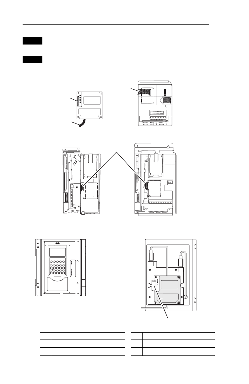
Step 3
Step 4
If the adapter has address or data rate switches, set them to appropriate
positions. See the adapter User Manual for complete details.
Connect one end of the Internal Interface cable to the DPI port on the
drive and the other end to the mating DPI connector on the adapter.
(20-COMM-E EtherNet/IP
Adapter shown as example)
➋
➌
➊
PowerFlex 70 - All Frames
➍
PowerFlex 700 Frames 0 and 1
PowerFlex 700S Frames 0 and 1
HIM panel opens to
allow access to DPI
interface. To open
Item Description Item Description
15.24 cm (6 in.) Internal Interface cable
➊
DPI Connector
➋
panel, remove screws
on left side of HIM
panel and swing open.
PowerFlex 700H Frames 9 and Larger
PowerFlex 700S Frames 9 and Larger
PowerFlex 700 Frames 2 and Larger
PowerFlex 700S Frames 2 through 6
X2
Network cable
➌
2.54 cm (1 in.) Internal Interface cable
➍
X1
➍
Page 3

Step 5
3
Secure and ground the adapter to the drive by doing the following:
• On a PowerFlex 70 drive, fold the Internal Interface cable behind the
adapter and mount the adapter on the drive using the four captive
screws. Use the torque recommended in the drawing.
• On a PowerFlex 700, PowerFlex 700H drive or PowerFlex 700S drive,
mount the adapter on the drive using the four captive screws. Use the
torque recommended in the drawing.
0.9 N-m
(8.0 lb.-in.)
4 Places
Drive
Adapter
Internal Interface Cable
folded behind the adapter
and in front of the drive.
PowerFlex 70 - All Frame Sizes
(Adapter mounts in drive.)
PowerFlex 700 Frames 0 and 1
PowerFlex 700S Frames 0 and 1
(Adapter mounts on door.)
X2
0.9 N-m
(8.0 lb.-in.)
4 Places
PowerFlex 700H Frames 9 and Larger
PowerFlex 700S Frames 9 and Larger
(Adapter mounts behind HIM panel.)
0.9 N-m
(8.0 lb.-in.)
4 Places
PowerFlex 700 Frames 2 and Larger
PowerFlex 700S Frames 2 through 6
(Adapter mounts in drive.)
X1
Ground Tab Detail
Verify metal ground tab is bent 90°
and is under the adapter before
tightening screw. After tightening
the screw, verify continuity exists
between the head of the screw
and drive ground.
Verify metal ground tab is bent 90° and
is under the adapter before tightening
screw. After tightening the screw, verify
continuity exists between the head of
the screw and drive ground.
Page 4

A
A
Step 6
Step 7
Step 8
Connect one end of the network cable to the network. Make sure to use
the proper cable for the network. See the adapter User Manual’s “Related
Documentation” section for appropriate publication(s).
Route the other end of the network cable to the outside of the drive, and
connect the cable to the adapter using the adapter’s mating socket or
terminal block. For complete wiring details, see the adapter User Manual.
Important: Make sure to properly route, wire, and ground the cable.
Always separate the communications wiring from the power
and motor wiring. For more information, see Wiring and
Grounding Guidelines for PWM AC Drives.
Read the adapter User Manual for information to configure and
determine how to apply the network to the host product.
U.S. Allen-Bradley Drives Technical Support
Tel: (1) 262.512.8176, Fax: (1) 262.512.2222, Email: support@drives.ra.rockwell.com, Online: www.ab.com/support/abdrives
www.rockwellautomation.com
Power, Control and Information Solutions Headquarters
mericas: Rockwell Automation, 1201 South Second Street, Milwaukee, WI 53204-2496 USA, Tel: (1) 414.382.2000, Fax: (1) 414.382.4444
Europe/Middle East/Africa: Rockwell Automation, Vorstlaan/Boulevard du Souverain 36, 1170 Brussels, Belgium, Tel: (32) 2 663 0600, Fax: (32) 2 663 0640
sia Pacific: Rockwell Automation, Level 14, Core F, Cyberport 3, 100 Cyberport Road, Hong Kong, Tel: (852) 2887 4788, Fax: (852) 2508 1846
Publication 20COMM-IN004A-EN-P –January, 2008 P/N 376902-P01
Copyright © 2008 Rockwell Automation, Inc. All rights reserved. Printed in USA.
 Loading...