

Page 1

Quick Start
Micro800 Programmable Controllers: Getting Started with
Motion Control Using a Simulated Axis
Catalog Numbers Bulletin 2080-LC30, 2080-LC50
Page 2
Important User Information
IMPORTANT
Solid-state equipment has operational characteristics differing from those of electromechanical equipment. Safety
Guidelines for the Application, Installation and Maintenance of Solid State Controls (publication SGI-1.1
your local Rockwell Automation sales office or online at http://www.rockwellautomation.com/literature/
important differences between solid-state equipment and hard-wired electromechanical devices. Because of this difference,
and also because of the wide variety of uses for solid-state equipment, all persons responsible for applying this equipment
must satisfy themselves that each intended application of this equipment is acceptable.
In no event will Rockwell Automation, Inc. be responsible or liable for indirect or consequential damages resulting from the
use or application of this equipment.
The examples and diagrams in this manual are included solely for illustrative purposes. Because of the many variables and
requirements associated with any particular installation, Rockwell Automation, Inc. cannot assume responsibility or
liability for actual use based on the examples and diagrams.
No patent liability is assumed by Rockwell Automation, Inc. with respect to use of information, circuits, equipment, or
software described in this manual.
Reproduction of the contents of this manual, in whole or in part, without written permission of Rockwell Automation,
Inc., is prohibited.
Throughout this manual, when necessary, we use notes to make you aware of safety considerations.
available from
) describes some
WARNING: Identifies information about practices or circumstances that can cause an explosion in a hazardous environment,
which may lead to personal injury or death, property damage, or economic loss.
ATTENTION: Identifies information about practices or circumstances that can lead to personal injury or death, property
damage, or economic loss. Attentions help you identify a hazard, avoid a hazard, and recognize the consequence.
SHOCK HAZARD: Labels may be on or inside the equipment, for example, a drive or motor, to alert people that dangerous
voltage may be present.
BURN HAZARD: Labels may be on or inside the equipment, for example, a drive or motor, to alert people that surfaces may
reach dangerous temperatures.
Identifies information that is critical for successful application and understanding of the product.
Allen-Bradley, Micro800, Micro830, Micro850, Connected Components Workbench, PanelView, Rockwell Software, Rockwell Automation, and TechConnect are trademarks of Rockwell Automation, Inc.
Trademarks not belonging to Rockwell Automation are property of their respective companies.
Page 3

Preface
About This Publication
This quick start is designed to provide instructions for implementing a motion
control project using Connected Components Workbench™ software and a
Micro830™/Micro850™ programmable logic controller (PLC). It makes use
of a sample project to illustrate the basic steps that a user needs to perform to
use the motion control feature in Micro830 and Micro850 controllers.
To assist in the design and installation of your system, refer to the Micro830
and Micro850 Programmable Controllers User Manual, publication
2080-UM002
The beginning of each chapter contains the following information. Read these
sections carefully before beginning work in each chapter.
• Before You Begin – This section lists the steps that must be completed
• What You Need – This section lists the tools that are required to
• Follow These Steps – This illustrates the steps in the current chapter
.
and decisions that must be made before starting that chapter. The
chapters in this quick start do not have to be completed in the order in
which they appear, but this section defines the minimum amount of
preparation required before completing the current chapter.
complete the steps in the current chapter. This includes, but is not
limited to, hardware and software.
and identifies which steps are required to complete the examples using
specific networks.
Audience
Required Software
To be able to use the motion control feature effectively, you need to be familiar
with programming in function block diagram, structured text, and ladder
programming.
This quick start works hand-in-hand with Micro830 and Micro850
Programmable Controllers User Manual, publication 2080-UM002
To complete this quick start, the following software is required:
• Connected Components Workbench revision 2 and later
Connected Components Workbench is the main programming software
for Micro800 systems. It provides a choice of IEC 61131-3
programming languages (ladder diagram, function block diagram,
structured text) with user defined function block support that optimizes
machine control.
You will need the Connected Components Workbench software to
configure your axis parameters, write your motion control function
block programs, execute your function blocks, and monitor your axis
status.
.
iiiPublication 2080-QS001A-EN-E - January 2013 iii
Page 4

Preface
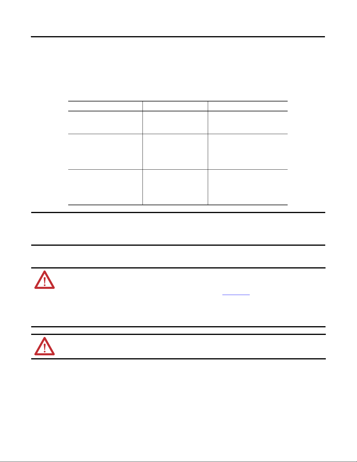
Additional Resources
Resource Description
Micro830 and Micro850 User Manual, publication
2080-UM002
Micro800 Programmable Controller External AC Power
Supply Installation Instructions, publication 2080-IN001
A detailed description of how to install and use your Micro830 and Micro850
programmable controller and expansion I/O system.
Information on wiring and installing the optional AC power supply.
Kinetix 3 Motion Control Indexing Application,
publication CC-QS025
Industrial Automation Wiring and Grounding Guidelines,
publication 1770-4.1
Connected Components Workbench Online Help Online Help that provides a description of the different elements of the
Quick start instructions designed to provide instructions for implementing a
Kinetix® 3 component-class drive motion control indexing application by using
Connected Components Workbench software and a Micro830 programmable
logic controller (PLC).
More information on proper wiring and grounding techniques.
Connected Components Workbench software.
iv Publication 2080-QS001A-EN-E - January 2013
Page 5

Create a Micro800 Project
Table of Contents
Important User Information . . . . . . . . . . . . . . . . . . . . . . . . . . . . . . . . . . . . . . . . ii
Preface
About This Publication . . . . . . . . . . . . . . . . . . . . . . . . . . . . . . . . . . . . . . . . . . . iii
Audience . . . . . . . . . . . . . . . . . . . . . . . . . . . . . . . . . . . . . . . . . . . . . . . . . . . . . . . . . iii
Required Software. . . . . . . . . . . . . . . . . . . . . . . . . . . . . . . . . . . . . . . . . . . . . . . . . iii
Additional Resources . . . . . . . . . . . . . . . . . . . . . . . . . . . . . . . . . . . . . . . . . . . . . . iv
Where to Start
Overview of Sample Project . . . . . . . . . . . . . . . . . . . . . . . . . . . . . . . . . . . . . . . .vii
Optional: PanelView Component . . . . . . . . . . . . . . . . . . . . . . . . . . . . . . . . . .vii
Hardware and Software Compatibility . . . . . . . . . . . . . . . . . . . . . . . . . . . . . viii
Follow These Steps . . . . . . . . . . . . . . . . . . . . . . . . . . . . . . . . . . . . . . . . . . . . . . . . ix
Chapter 1
Introduction . . . . . . . . . . . . . . . . . . . . . . . . . . . . . . . . . . . . . . . . . . . . . . . . . . . . . .1
Before You Begin . . . . . . . . . . . . . . . . . . . . . . . . . . . . . . . . . . . . . . . . . . . . . . . . . . 1
What You Need . . . . . . . . . . . . . . . . . . . . . . . . . . . . . . . . . . . . . . . . . . . . . . . . . . . 1
Create a Micro800 Project in Connected Components Workbench . . . . 2
Configure Motion Axis Properties
Write Your Motion Control Programs
Chapter 2
Introduction . . . . . . . . . . . . . . . . . . . . . . . . . . . . . . . . . . . . . . . . . . . . . . . . . . . . . .5
Before You Begin . . . . . . . . . . . . . . . . . . . . . . . . . . . . . . . . . . . . . . . . . . . . . . . . . . 5
What You Need . . . . . . . . . . . . . . . . . . . . . . . . . . . . . . . . . . . . . . . . . . . . . . . . . . . 5
Follow These Steps . . . . . . . . . . . . . . . . . . . . . . . . . . . . . . . . . . . . . . . . . . . . . . . . . 6
Configure General Properties . . . . . . . . . . . . . . . . . . . . . . . . . . . . . . . . . . . . . . .7
Configure Motor and Load Properties . . . . . . . . . . . . . . . . . . . . . . . . . . . . . . .9
Configure Limits Properties . . . . . . . . . . . . . . . . . . . . . . . . . . . . . . . . . . . . . . .10
Configure Dynamics Properties . . . . . . . . . . . . . . . . . . . . . . . . . . . . . . . . . . . .11
Configure Homing Properties . . . . . . . . . . . . . . . . . . . . . . . . . . . . . . . . . . . . .12
Configure Embedded I/O Properties . . . . . . . . . . . . . . . . . . . . . . . . . . . . . . .13
Chapter 3
Introduction . . . . . . . . . . . . . . . . . . . . . . . . . . . . . . . . . . . . . . . . . . . . . . . . . . . . .15
Before You Begin . . . . . . . . . . . . . . . . . . . . . . . . . . . . . . . . . . . . . . . . . . . . . . . . .15
What You Need . . . . . . . . . . . . . . . . . . . . . . . . . . . . . . . . . . . . . . . . . . . . . . . . . .15
Follow These Steps . . . . . . . . . . . . . . . . . . . . . . . . . . . . . . . . . . . . . . . . . . . . . . . .16
Create Axis_PowerUp Program . . . . . . . . . . . . . . . . . . . . . . . . . . . . . . . . . . . .17
Create Homing Program . . . . . . . . . . . . . . . . . . . . . . . . . . . . . . . . . . . . . . . . . .21
Create Program for MC_MoveRelative . . . . . . . . . . . . . . . . . . . . . . . . . . . . .28
Create Program for MC_MoveAbsolute Function Block . . . . . . . . . . . . .31
Create Program for MC_MoveVelocity Function Block . . . . . . . . . . . . .36
Create Program for MC_TouchProbe Function Block . . . . . . . . . . . . . . .43
Build and Download Programs . . . . . . . . . . . . . . . . . . . . . . . . . . . . . . . . . . . . .48
v Publication 2080-QS001A-EN-E - January 2013
Page 6

vi Table of Contents
Wire Your Controller for Motion Control
Execute Your Motion Control Function Blocks
Chapter 4
Introduction . . . . . . . . . . . . . . . . . . . . . . . . . . . . . . . . . . . . . . . . . . . . . . . . . . . . .49
What You Need . . . . . . . . . . . . . . . . . . . . . . . . . . . . . . . . . . . . . . . . . . . . . . . . . .49
Wire the Controller . . . . . . . . . . . . . . . . . . . . . . . . . . . . . . . . . . . . . . . . . . . . . . .50
Chapter 5
Introduction . . . . . . . . . . . . . . . . . . . . . . . . . . . . . . . . . . . . . . . . . . . . . . . . . . . . .51
Before You Begin . . . . . . . . . . . . . . . . . . . . . . . . . . . . . . . . . . . . . . . . . . . . . . . . .51
What You Need . . . . . . . . . . . . . . . . . . . . . . . . . . . . . . . . . . . . . . . . . . . . . . . . . .51
Follow These Steps . . . . . . . . . . . . . . . . . . . . . . . . . . . . . . . . . . . . . . . . . . . . . . . .52
Go to Remote RUN Mode . . . . . . . . . . . . . . . . . . . . . . . . . . . . . . . . . . . . . . . .52
Axis Monitoring . . . . . . . . . . . . . . . . . . . . . . . . . . . . . . . . . . . . . . . . . . . . . . . . . .53
Power Up the Motion Axis . . . . . . . . . . . . . . . . . . . . . . . . . . . . . . . . . . . . . . . .54
Execute MC_Home . . . . . . . . . . . . . . . . . . . . . . . . . . . . . . . . . . . . . . . . . . . . . . .55
Execute MC_MoveRelative . . . . . . . . . . . . . . . . . . . . . . . . . . . . . . . . . . . . . . . .58
Execute MC_MoveAbsolute . . . . . . . . . . . . . . . . . . . . . . . . . . . . . . . . . . . . . . .61
Execute MC_MoveVelocity and MC_Halt . . . . . . . . . . . . . . . . . . . . . . . . .66
Execute MC_TouchProbe . . . . . . . . . . . . . . . . . . . . . . . . . . . . . . . . . . . . . . . . .69
Implementing Motion Control in an Actual Environment . . . . . . . . . . .70
Publication 2080-QS001A-EN-E - January 2013
Page 7

Where to Start
Micro850
controller
Simulated Linear Actuator
Home
Sensor
Direction
output
Pulse Train
Output
Upper
Limit
moving
object
PanelView
Component
Lower
Limit
optional component
TIP
HSC wiring for PTO feedback is not shown and is for simulation purposes only.
Overview of Sample Project
This quick start instruction serves to enable users to the use the motion control feature on Micro830 and Micro850
controllers. It uses a sample simulation program to familiarize the user with motion control instructions and related
parameter and wiring configurations. In particular, this project lets the user enable an axis, home an axis, move an axis, and
use touch probe to capture current position in a simulated environment.
The project uses the minimum components to use motion control. It does not require a servo drive. The PTO output is
wired directly to the high speed counter input. It makes use of high speed counter inputs to count the pulse train output
(PTO) for the current position.
The following diagram illustrates how this project simulates motion control. The elements of this project are shown in the
following diagram.
Download the Simulation Project
You can also download the code for the complete simulation project from the following link:
http://www.rockwellautomation.com/go/scmicro800
The downloadable code includes an optional PanelView Component (PVc) program, which allows the user to easily update
and monitor different axis parameters through a PVc screen.
If you opt not to use a PanelView Component, use the Connected Components Workbench software to toggle variable
input values and trigger motion instructions. Axis monitoring can also be done through the same software through the Axis
Monitor feature.
To get started, check that your Micro800 controller supports motion control.
viiPublication 2080-QS001A-EN-E - January 2013 vii
Page 8
Where to Start
IMPORTANT
Hardware and Software Compatibility
The motion control feature on Micro830 and Micro850 controller is implemented through Pulse Train Outputs (PTOs)
and motion axes, which are summarized in the following table.
PTO and Motion Axis Support on Micro830 and Micro850 Controllers
Controller PTO (built-in) Number of Axes Supported
10/16 Points
2080-LC30-10QVB
2080-LC30-16QVB
24 Points
2080-LC30-24QVB
2080-LC30-24QBB
2080-LC50-24QVB
2080-LC50-24QBB
48 Points
2080-LC30-48QVB
2080-LC30-48QBB
2080-LC50-48QVB
2080-LC50-48QBB
Software and Firmware Requirements
• For programming, motion control is supported on Connected Components Workbench software
revision 2 and later.
• Micro830 controllers require firmware revision 2 and later.
11
22
33
ATTENTION: To use the Micro800 motion control feature effectively, users need to have a basic
understanding of the following:
• PTO components and parameters
See the Micro830 and Micro850 User Manual, publication 2080-UM002
components and their relationships.
• Programming and working with elements in the Connected Components Workbench software
The user needs to have a working knowledge of ladder diagram, structured text, or function block diagram
programming to be able to work with motion function blocks, variables, and axis configuration parameters.
, for a general overview of Motion
ATTENTION: To learn more about Connected Components Workbench and detailed descriptions of the
variables for the Motion Function Blocks, you can refer to Connected Components Workbench Online Help that
comes with your Connected Components Workbench installation.
viii Publication 2080-QS001A-EN-E - January 2013
Page 9
Where to Start
Upper
Right
Limit
Lower
Left
Limit
Home
Sensor
The axis moves 200 mm relative to the current position.
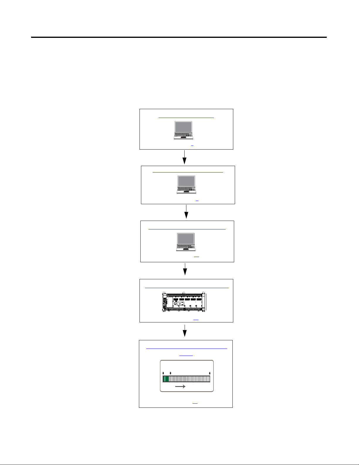
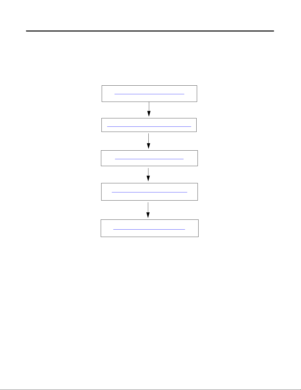
Configure Motion Axis Properties
Write Your Motion Control Programs
Create a Micro800 Project
Wire Your Controller for Motion Control
See page 1
See page 5
See page 15
See page 49
Execute Your Motion Control Function
Blocks
See page 51
Follow These Steps
The major subsections for this quick start project are outlined in the following flowchart. Follow the steps under each
subsection to become familiar with the required procedure to configure your controller and set up a simulation project for
motion control.
Publication 2080-QS001A-EN-E - January 2013 ix
Page 10

Where to Start
Notes:
x Publication 2080-QS001A-EN-E - January 2013
Page 11

Chapter
Create a Micro800 Project
Introduction
In this chapter, you will create a sample Micro830/Micro850 controller project through the Connected Components
Wor kb en ch .
Before You Begin
Ensure that you have Connected Components Workbench revision 2 properly installed.
1
What You Need
• Connected Components Workbench revision 2 or later
• Firmware revision 2 and later for Micro830 controllers
1Publication 2080-QS001A-EN-E - January 2013 1
Page 12
Chapter 1 Create a Micro800 Project
TIP
IMPORTANT
IMPORTANT
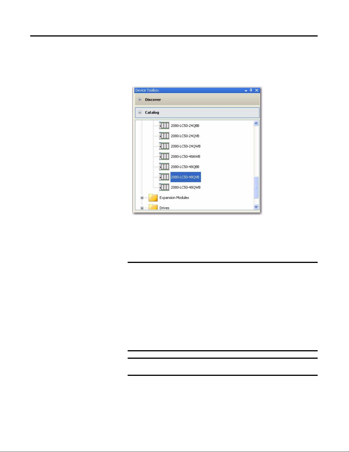
Create a Micro800 Project in Connected Components Workbench
Launch the Connected Components Workbench software.
1. On the Device Toolbox, expand the list of Controllers by clicking the + sign.
If your controller is online, use the Discover feature to
automatically discover your controller.
Make sure that your controller is one of the following
compatible controllers:
• 2080-LC30-24QBB
• 2080-LC30-24QVB
• 2080-LC30-48QBB
• 2080-LC30-48QVB
• 2080-LC50-24QBB
• 2080-LC50-24QVB
• 2080-LC50-48QBB
• 2080-LC50-48QVB
Motion control on Micro830 controllers require firmware revision 2
or later.
2 Publication 2080-QS001A-EN-E - January 2013
Page 13
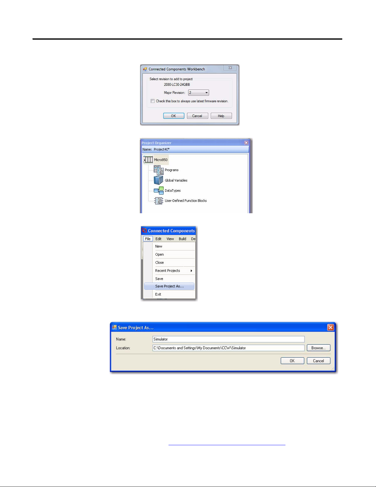
2. Select major revision 2 when
TIP
manually adding a Micro830
controller.
3. Drag your controller onto the Project Organizer pane.
Create a Micro800 Project Chapter 1
4. Go to File → Save Project As.
Then, provide a project name for
your project.
5. Click OK.
Optional PanelView Component Program
This simulation project can also include a PanelView Component program to
allow for easier monitoring and toggling of axis parameter values through a
PVc screen. The code for this optional program is downloadable from the
following link, along with the complete code for this project:
http://www.rockwellautomation.com/go/scmicro800
Publication 2080-QS001A-EN-E - January 2013 3
Page 14

Chapter 1 Create a Micro800 Project
Notes:
4 Publication 2080-QS001A-EN-E - January 2013
Page 15

Configure Motion Axis Properties
Introduction
In this chapter, you will configure the axis parameters through Connected Components Workbench.
Topic Page
Configure General Properties 7
Configure Motor and Load Properties 9
Configure Limits Properties 10
Configure Dynamics Properties 11
Configure Homing Properties 12
Chapter
2
Before You Begin
Acquire a basic understanding of the different motion axis parameters by referring to the Micro830 and Micro850
Programmable Controllers User Manual, publication 2080-UM002
Online Help.
and/or the Connected Components Workbench
What You Need
• Connected Components Workbench revision 2 or later
• Firmware revision 2 and later for Micro830 controllers
5Publication 2080-QS001A-EN-E - January 2013 5
Page 16
Chapter 2 Configure Motion Axis Properties
Configure General Properties on page 7
Configure Motor and Load Properties on page 9
Configure Limits Properties on page 10
Configure Dynamics Properties on page 11
Configure Homing Properties on page 12
Follow These Steps
To configure your axis, follow these steps.
6 Publication 2080-QS001A-EN-E - January 2013
Page 17

Configure General Properties
Launch the Connected Components Workbench software.
Configure Motion Axis Properties Chapter 2
1. Open the project you have created in the previous chapter.
2. On the Project Organizer pane, double-click the controller name to bring up the Device Properties pane.
3. Under the Controller properties tree, go to Motion. Right-click <New Axis> and choose Create.
4. Provide the name "Simulator" for the axis. Alternatively, you can press F2 to name the axis.
Publication 2080-QS001A-EN-E - January 2013 7
Page 18
Chapter 2 Configure Motion Axis Properties
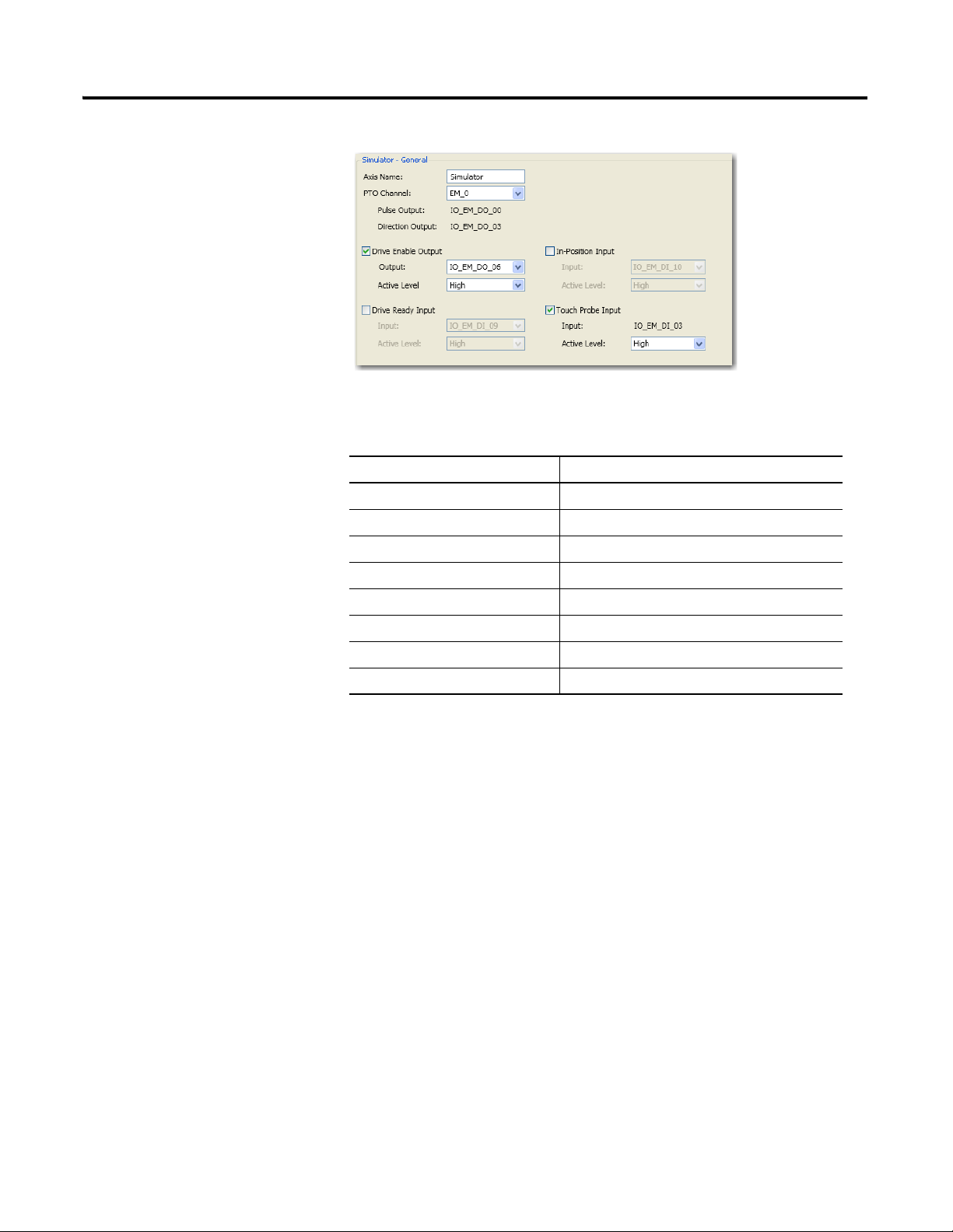
5. Click General to bring up the General properties tab.
6. Configure the general properties as shown in the table.
General Properties Parameters
Parameter Value
Axis Name Simulator
PTO Channel EM_0
Enable Drive Enable Output Tick option box to enable
Drive Enable Output IO_EM_DO_06
Drive Enable Output Active Level High
Enable Touch Probe Input Tick option box to enable
Touch Probe Input IO_EM_DI_03
Touch Probe Input Active Level High
8 Publication 2080-QS001A-EN-E - January 2013
Page 19
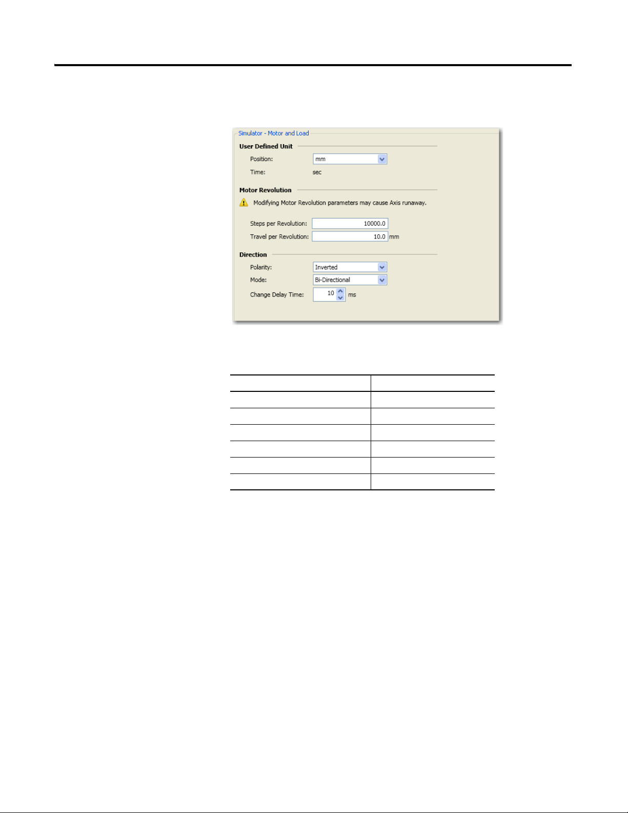
Configure Motor and Load Properties
1. On the Controller Configuration tree, under Motion, click Motor and Load to bring up the Motor and Load tab.
Configure Motion Axis Properties Chapter 2
2. Configure Motor and Load parameters as follows.
Motor and Load Properties
Parameter Value
Position mm
Steps per revolution 10000
Travel per revolution 10 mm
Polarity Inverted
Mode Bi-directional
Change delay time 10 ms
Publication 2080-QS001A-EN-E - January 2013 9
Page 20

Chapter 2 Configure Motion Axis Properties
Configure Limits Properties
1. On the Controller Configuration tree, under Motion, click Limits to bring up the Limits properties tab.
2. Configure Limits parameters as shown in the table.
Limits Properties
Parameter Value
When hard limits is reached, apply Emergency Stop Profile
Lower Hard Limit Tick option box to enable
Lower Hard Limit Active Level High
Upper Hard Limit Tick option box to enable
Upper Hard Limit Active Level High
10 Publication 2080-QS001A-EN-E - January 2013
Page 21
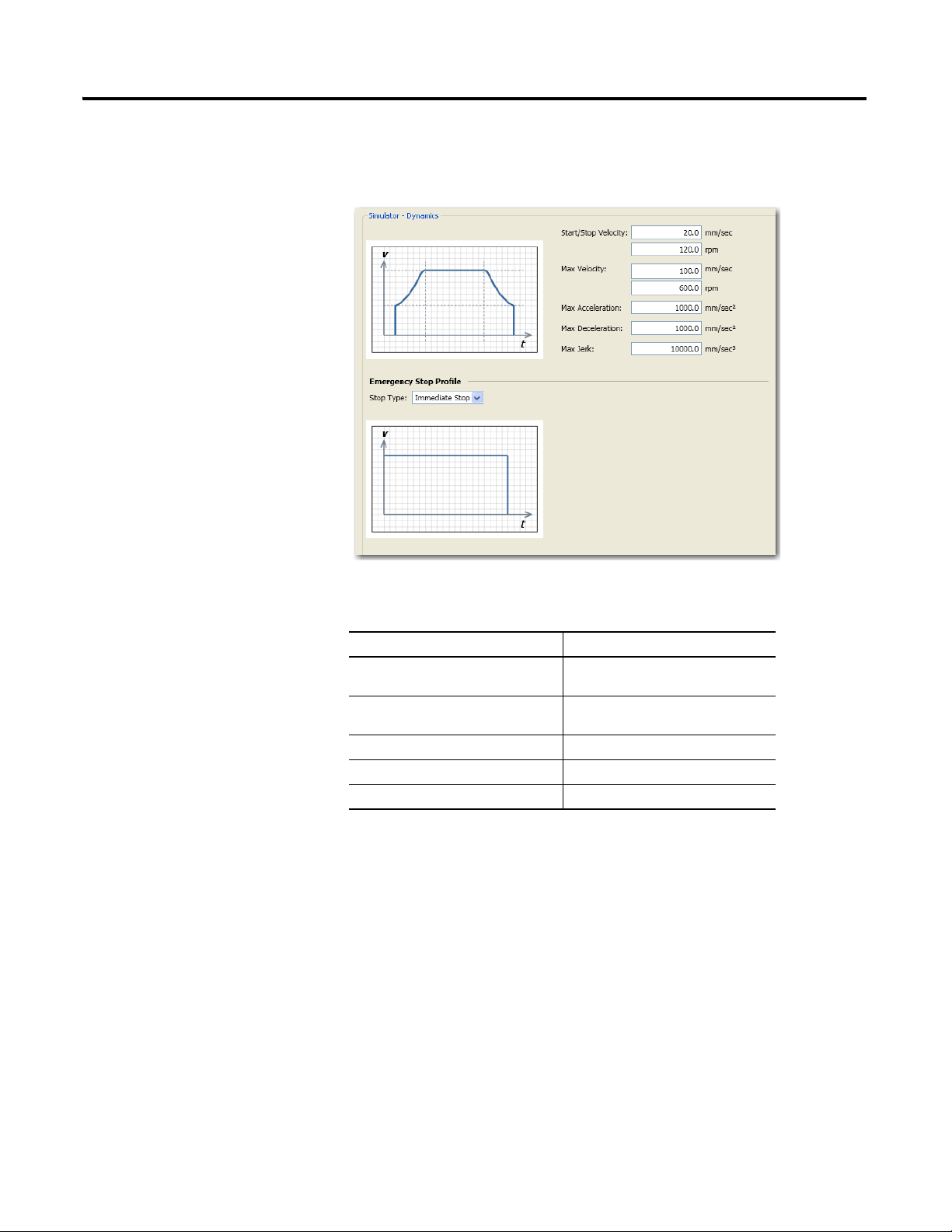
Configure Dynamics Properties
1. Under Motion, click Dynamics to bring up the Dynamics properties tab.
Configure Motion Axis Properties Chapter 2
2. Configure Dynamics parameters as shown in the table.
Dynamics Properties
Parameter Value
Start/Stop Velocity 20.0 mm/sec
120.0 rpm
Max Velocity 100.0 mm/sec
600.0 rpm
Max Acceleration 1000 mm/sec
Max Deceleration 1000 mm/sec
Max Jerk 10000 mm/sec
2
2
3
Publication 2080-QS001A-EN-E - January 2013 11
Page 22
Chapter 2 Configure Motion Axis Properties
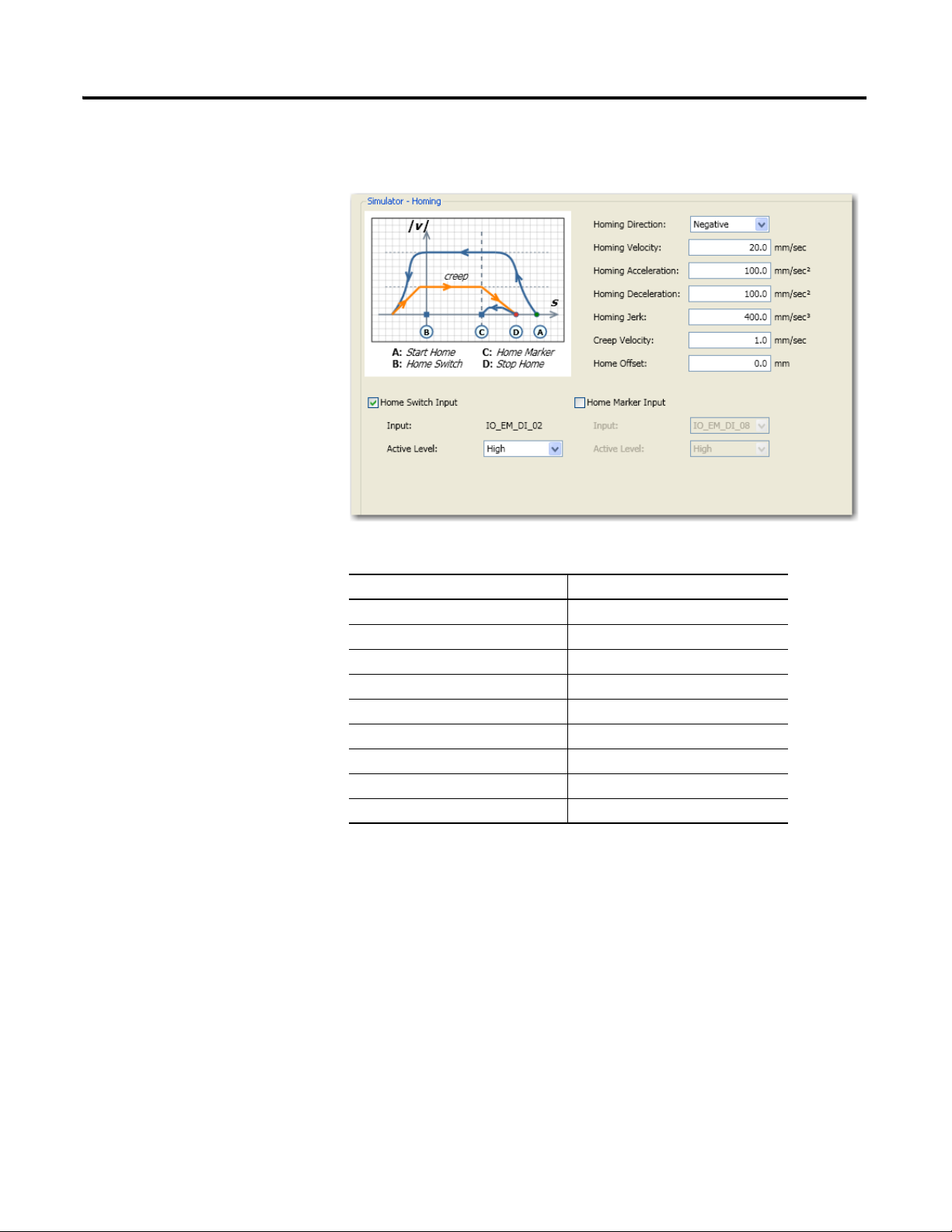
Configure Homing Properties
1. Under Motion, click Homing to bring up the Homing properties tab.
2. Configure homing parameters as shown in the table.
Parameter Value
Homing Direction Negative
Homing Velocity 20 mm/sec
Homing Acceleration 100 mm/sec
Homing Deceleration 100 mm/sec
Homing Jerk 400 mm/sec
Creep Velocity 1.0 mm/sec
Home Offset 0.0 mm
Home Switch Input Tick option box to enable
Home Switch Input Active Level High
2
2
3
12 Publication 2080-QS001A-EN-E - January 2013
Page 23
Configure Motion Axis Properties Chapter 2
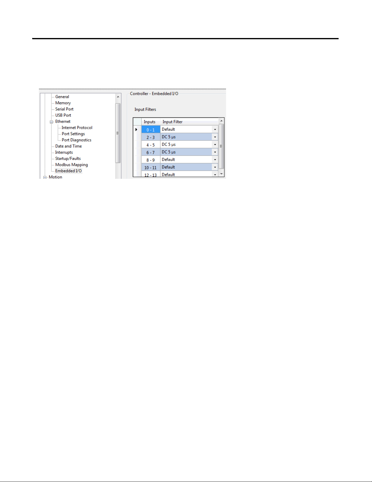
Configure Embedded I/O Properties
Go to Controller Properties → Embedded I/O, and update the input filter values as shown below.
Input filters are configured so that high speed pulse from the PTO is properly captured. When High Speed Counters and
Touch Probe are used, input filters need to be configured to match the high speed input.
Publication 2080-QS001A-EN-E - January 2013 13
Page 24

Chapter 2 Configure Motion Axis Properties
Notes:
14 Publication 2080-QS001A-EN-E - January 2013
Page 25

Chapter
3
Write Your Motion Control Programs
Introduction
In this chapter, you will write movement function block programs that will allow you to control the movement profile of
your axis.
Topic Page
Create Axis_PowerUp Program 17
Create Homing Program 21
Create Program for MC_MoveRelative 28
Create Program for MC_MoveAbsolute Function Block 31
Create Program for MC_MoveVelocity Function Block 36
Create Program for MC_TouchProbe Function Block 43
Before You Begin
Learn about motion control function blocks by referring to the Micro830 and Micro850 Programmable Controllers User
Manual, publication 2080-UM002
, and the Connected Components Workbench Online Help.
What You Need
• Connected Components Workbench revision 2 or later
• Firmware revision 2 and later for Micro830 controllers
15Publication 2080-QS001A-EN-E - January 2013 15
Page 26

Chapter 3 Write Your Motion Control Programs
Create Axis_PowerUp Program on page17
Create and Assign Variables and Values for
the Axis_PowerUp Program on page19
Create Homing Program on page21
Create and Assign Variables and Values for the
MC_Home Function Block on page26
Create Program for MC_MoveRelative on
page28
Create and Assign Variables and Values to the
MC_MoveRelative Function Block on page30
Create Program for MC_MoveAbsolute
Function Block on page31
Create and Assign Variables and Values to the
MC_MoveAbsolute Function Block on page34
Create Program for MC_MoveVelocity
Function Block on page36
Create and Assign Variables and Values to the
MC_MoveVelocity Function Block on page41
Create Program for MC_TouchProbe Function
Block on page43
Create and Assign Variables and Values to the
Action_TouchProbe program on page47
Follow These Steps
To write your motion control function blocks, follow these steps.
16 Publication 2080-QS001A-EN-E - January 2013
Page 27

Create Axis_PowerUp Program
1. Open the project for your controller in Connected Components Workbench.
Write Your Motion Control Programs Chapter 3
2. On the Project Organizer pane, right-click Programs, select Add New LD : Ladder Diagram. Press F2 to rename the program to Axis_PowerUp. Press Enter.
3. Right-click Axis_PowerUp program, choose Open.
4. From the Toolbox, double-click Block to add it to the rung. Alternatively, you can drag and drop Block onto the rung. Your ladder rung should appear as shown.
Publication 2080-QS001A-EN-E - January 2013 17
Page 28

Chapter 3 Write Your Motion Control Programs
Your ladder rung should appear as follows.
5. On the Instruction Block Selector window that appears, type MC_Power on the default entry field to filter the MC_Power function block. Choose MC_Power. Click OK.
6. From the Toolbox, double-click Block to add it to the rung. Alternatively, you can drag and drop Block onto the rung.
18 Publication 2080-QS001A-EN-E - January 2013
Page 29

7. On the Instruction Block
Your ladder rung should appear as follows.
Selector window that appears,
type MC_Reset on the default
entry field. Choose MC_Reset
and click OK.
Write Your Motion Control Programs Chapter 3
Create and Assign Variables and Values for the Axis_PowerUp Program
1. On the Project Organizer pane, double-click Global Variables to bring up the Variables window. Add the following variables with these corresponding data types and initial values.
Publication 2080-QS001A-EN-E - January 2013 19
Variables and Initial Values for Axis_PowerUp Program
Variable Name Data Type Initial Value
Simulator AXIS_REF
PowerUpAxis BOOL TRUE
PowerDone BOOL
SWReset BOOL False
Page 30

Chapter 3 Write Your Motion Control Programs
2. Assign the variables to the function block elements as shown.
20 Publication 2080-QS001A-EN-E - January 2013
Page 31

Create Homing Program
Write Your Motion Control Programs Chapter 3
1. Click Programs, select Add →
New LD : Ladder Diagram.
Press F2 and rename the
program to Action_Homing.
2. From the Toolbox, double-click Block to add it to the rung. Alternatively, you can drag and drop Block onto the rung.
Publication 2080-QS001A-EN-E - January 2013 21
Page 32

Chapter 3 Write Your Motion Control Programs
3. On the Instruction Block Selector window that appears, type MC_Home on the default entry field to filter out MC_Home.
4. Choose MC_Home. Click OK. Your ladder rung should appear as follows.
5. Create a second rung. From the Toolbox, select Rung and drag it onto the space just below the first rung.
22 Publication 2080-QS001A-EN-E - January 2013
Page 33

6. Select Branch from the Toolbox and drag it onto the second rung.
7. Select Direct Contact from the Toolbox and drag it onto the second rung as shown.
8. Select Direct Contact from the Toolbox and drag it onto the branch on the second rung as shown.
Write Your Motion Control Programs Chapter 3
9. Create a third rung. From the Toolbox, select rung and drag it onto the space just below the second rung.
10. Select Pulse Rising Edge Direct Contact from the Toolbox and drag it onto the third rung.
11. Select Set Coil from the Toolbox and drag it onto the third rung. Your third rung should appear as follows.
Publication 2080-QS001A-EN-E - January 2013 23
Page 34

Chapter 3 Write Your Motion Control Programs
12. Create a fourth rung. From the Toolbox, select rung and drag it onto the space just below the third rung.
13. Select Branch from the Toolbox and drag it onto the fourth rung.
14. Select Pulse Rising Edge Direct
Contact from the Toolbox and
drag it onto the fourth rung as
shown.
15. Select Block from the Toolbox and drag it onto the branch on fourth rung as shown.
24 Publication 2080-QS001A-EN-E - January 2013
Page 35

16. On the Instruction Block Selector window that appears, type TON to filter out the TON function block. Choose TON. Click OK
Write Your Motion Control Programs Chapter 3
17. Select Block from the Toolbox and drag it onto the branch on the fourth rung as shown.
18. On the Instruction Block Selector window that appears, type R_TRIG to filter out the R_TRIG function block. Choose R_TRIG. Click OK
Publication 2080-QS001A-EN-E - January 2013 25
Page 36

Chapter 3 Write Your Motion Control Programs
19. Select Reset Coil from the Toolbox and drag it onto the fourth rung as shown.
Create and Assign Variables and Values for the MC_Home Function Block
1. Create the following Global Variables with the data types and initial values (if any) as shown in the table.
2. On the first rung, assign the variables for the MC_Home function block elements as shown.
Variable Name Data Type Initial Value
SWHome BOOL
HomeSetPos Real 110
BFMD SInt
t#1ms time
Simulator.AxisHomed BOOL
SWrstEncoder BOOL
26 Publication 2080-QS001A-EN-E - January 2013
Page 37

3. On the second rung, assign the variables as shown below.
4. On the third rung, assign the variables as shown below.
5. On the fourth rung, assign the variables as shown below.
Write Your Motion Control Programs Chapter 3
Publication 2080-QS001A-EN-E - January 2013 27
Page 38

Chapter 3 Write Your Motion Control Programs
Create Program for MC_MoveRelative
1. Click Programs, select Add →
New LD: Ladder Diagram.
Press F2 and rename the
program to
Action_MoveRelative.
2. From the Toolbox, select Reverse Contact and drag and drop it onto the rung.
28 Publication 2080-QS001A-EN-E - January 2013
Page 39

3. From the Toolbox, select Return and drag and drop it onto the rung. You r f ir st la dd er run g s ho ul d appear as shown.
4. Create a second rung. From the Toolbox, select Rung and drag and drop it just below the first rung.
5. From the Toolbox, select Block and drag and drop it onto the second rung.
Write Your Motion Control Programs Chapter 3
6. On the Instruction Block Selector window that appears, type MC_MoveRelative to filter out the MC_MoveRelative function block. Choose MC_MoveRelative. Click OK. Your second rung should appear as shown.
Publication 2080-QS001A-EN-E - January 2013 29
Page 40

Chapter 3 Write Your Motion Control Programs
Create and Assign Variables and Values to the MC_MoveRelative Function Block
1. Create the following Global Variables with these data types and initial values.
2. On the first rung, assign the variables as shown.
3. On the second rung, assign the variables as shown in the picture.
30 Publication 2080-QS001A-EN-E - January 2013
Page 41

Write Your Motion Control Programs Chapter 3
Create Program for MC_MoveAbsolute Function Block
Publication 2080-QS001A-EN-E - January 2013 31
Page 42

Chapter 3 Write Your Motion Control Programs
1. Click Programs, select Add →
New LD: Ladder Diagram.
Press F2 and rename the
program to
Action_MoveAbsolute.
2. From the Toolbox, select Reverse Contact and drag and drop it onto the rung.
3. From the Toolbox, select Return and drag and drop it onto the rung. You r f ir st la dd er run g s ho ul d appear as shown.
4. Create a second rung. From the Toolbox, select Rung and drag and drop it just below the first rung.
5. From the Toolbox, select Block and drag and drop it onto the second rung.
32 Publication 2080-QS001A-EN-E - January 2013
Page 43

6. On the Instruction Block Selector window that appears, type MC_MoveAbsolute to filter out the MC_MoveAbsolute function block. Choose MC_MoveAbsolute. Click OK. Your second rung should appear as shown in the picture.
Write Your Motion Control Programs Chapter 3
7. Create a third rung. From the Toolbox, select Rung and drag and drop it just below the second rung.
8. From the Toolbox, select Block and drag and drop it onto the third rung.
Publication 2080-QS001A-EN-E - January 2013 33
Page 44

Chapter 3 Write Your Motion Control Programs
9. On the Instruction Block Selector window that appears, type MC_MoveAbsolute to filter out the MC_MoveAbsolute function block. Choose MC_MoveAbsolute. Click OK. Your third rung should appear as shown in the picture.
Create and Assign Variables and Values to the MC_MoveAbsolute Function Block
1. Create the following Global Variables with these data types and initial values.
2. On the first rung, assign the variables as shown.
34 Publication 2080-QS001A-EN-E - January 2013
Page 45

3. On the second rung, assign the variables as shown.
Write Your Motion Control Programs Chapter 3
4. On the third rung, assign the variables as shown.
Publication 2080-QS001A-EN-E - January 2013 35
Page 46

Chapter 3 Write Your Motion Control Programs
Create Program for MC_MoveVelocity Function Block
36 Publication 2080-QS001A-EN-E - January 2013
Page 47

1. Click Programs, select Add →
New LD : Ladder Diagram.
Press F2 and rename the
program to
Action_MoveVelocity.
2. From the Toolbox, select Reverse Contact and drag and drop it onto the rung.
3. From the Toolbox, select Return and drag and drop it onto the rung. The first rung should appear as shown.
Write Your Motion Control Programs Chapter 3
4. Create a second rung. From the Toolbox, select Rung and drag and drop it onto the space just below the first rung.
5. From the Toolbox, select Block and drag and drop it onto the second rung.
Publication 2080-QS001A-EN-E - January 2013 37
Page 48

Chapter 3 Write Your Motion Control Programs
Your second rung should appear as follows:
6. On the Instruction Block Selector window that appears, type ANY_TO_SINT to filter out the function block. Choose ANY_TO_SINT. Click OK.
7. Create a third rung. From the Toolbox, select Rung and drag and drop it onto the space just below the second rung.
38 Publication 2080-QS001A-EN-E - January 2013
Page 49

8. On the Instruction Block
Your third rung should appear as follows:
Selector window that appears,
type MC_MoveVelocity to filter
out the MC_MoveVelocity
function block. Choose
MC_MoveVelocity. Click OK.
Write Your Motion Control Programs Chapter 3
9. Create a fourth rung. From the Toolbox, select Rung and drag and drop it onto the space just below the second rung.
Publication 2080-QS001A-EN-E - January 2013 39
Page 50

Chapter 3 Write Your Motion Control Programs
Your fourth rung should appear as shown:
10. From the Toolbox, select Block and drag and drop it onto the fourth rung.
11. On the Instruction Block Selector window that appears, type MC_Halt to filter out the MC_Halt function block. Choose MC_Halt. Click OK.
40 Publication 2080-QS001A-EN-E - January 2013
Page 51

Write Your Motion Control Programs Chapter 3
Create and Assign Variables and Values to the MC_MoveVelocity Function Block
1. Create the following Global variables with these data types and initial values.
2. On the first rung, assign the variables as shown in the following picture.
3. On the second rung, assign the variables as shown.
Publication 2080-QS001A-EN-E - January 2013 41
Page 52

Chapter 3 Write Your Motion Control Programs
4. On the third rung, assign the variables as shown.
5. On the fourth rung, assign the variables as shown.
42 Publication 2080-QS001A-EN-E - January 2013
Page 53

Write Your Motion Control Programs Chapter 3
Create Program for MC_TouchProbe Function Block
1. Click Programs, select Add →
New LD : Ladder Diagram.
Press F2 and rename the
program to
Action_TouchProbe.
2. From the Toolbox, select Reverse Contact and drag and drop it onto the rung.
Publication 2080-QS001A-EN-E - January 2013 43
Page 54

Chapter 3 Write Your Motion Control Programs
3. From the Toolbox, select Return and drag and drop it onto the rung. You r f ir st la dd er run g s ho ul d appear as shown.
4. Create a second rung. From the Toolbox, select Rung and drag and drop it below the first rung.
5. From the Toolbox, select Reverse Contact and drag and drop it onto the second rung.
6. From the Toolbox, select Direct Coil and drag and drop it onto the second rung.
7. Create a third rung. From the Toolbox, select Rung and drag and drop it below the second rung.
8. From the Toolbox, select Block and drag and drop it onto the third rung.
44 Publication 2080-QS001A-EN-E - January 2013
Page 55

9. On the Instruction Block
Your third rung should appear as shown.
Selector window that appears,
type MC_TouchProbe to filter
out the MC_TouchProbe
function block. Choose
MC_TouchProbe. Click OK.
Write Your Motion Control Programs Chapter 3
10. Create a fourth rung. From the Toolbox, select Rung and drag and drop it below the third rung.
Publication 2080-QS001A-EN-E - January 2013 45
Page 56

Chapter 3 Write Your Motion Control Programs
11. From the Toolbox, select Block and drag and drop it onto the fourth rung.
12. On the Instruction Block Selector window that appears, type R_TRIG to filter out the R_TRIG function block. Choose R_TRIG. Click OK.
13. From the Toolbox, select Block and drag and drop it onto the fourth rung.
46 Publication 2080-QS001A-EN-E - January 2013
Page 57

14. On the Instruction Block
Your fourth rung should appear as follows.
Selector window that appears,
type 1 gain to filter out 1 gain.
Choose 1 gain. Click OK.
Write Your Motion Control Programs Chapter 3
Create and Assign Variables and Values to the Action_TouchProbe program
1. Create the following Global Variables with these data types and initial values.
2. Assign variables to the elements on the first rung as shown.
Publication 2080-QS001A-EN-E - January 2013 47
Page 58

Chapter 3 Write Your Motion Control Programs
3. Assign variables to the elements on the second rung as shown.
4. Assign variables to the elements on the third rung as shown.
5. Assign variables to the elements on the fourth rung as shown.
6. Save the program.
Build and Download Programs
After writing the programs, build and download the user program into the controller.
48 Publication 2080-QS001A-EN-E - January 2013
Page 59

Wire Your Controller for Motion Control
IMPORTANT
Introduction
In this chapter, you will wire your controller based on the sample project wiring configuration.
The wiring diagram presented in this chapter serves the purpose of a simulation project only. To help you wire your
controller to an actual servo drive for motion control, refer to the chapter, "Positioning with Embedded Pulse Train
Outputs" in the Micro830 and Micro850 Programmable Controllers User Manual, 2080-UM002
What You Need
Chapter
.
4
• 2080-LC30-xxQVB, 2080-LC30-xxQBB, 2080-LC50-xxQBB, 2080-LC50-xxQVB controller
•PanelView Component (optional)
49Publication 2080-QS001A-EN-E - January 2013 49
Page 60

Chapter 4 Wire Your Controller for Motion Control
Input Terminal Block
Output Terminal Block
Wire the Controller
Wire the controller based on the wiring configuration indicated in the following drawing and table.
Input
Channel
COM0 I-01
123456789101112
I-00
+DC24 +CM0
123456789101112
Logical Variable
Name in Software
I-03
I-02
O-01
O-00-DC24
I-04
-CM0
I-05
I-06 COM1
+CM1
O-02 O-04
I-07
O-03
Description Output
Channel
I-08
I-10
13 14 15 16
I-09
O-05
I-11
O-07
13 14 15 16
O-06
O-08
Logical Variable Name
in Software
I-12
I-13
O-09
-CM1
Description
2 _IO_EM_DI_00 Limit_L 4 _IO_EM_DO_00 PTO0
3 _IO_EM_DI_01 Limit_R 5 _IO_EM_DO_01
4 _IO_EM_DI_02 Home 8 _IO_EM_DO_02
5 _IO_EM_DI_03 Probe 9 _IO_EM_DO_03 DIR0
6 _IO_EM_DI_04 PTO0-IN 10 _IO_EM_DO_04 Driver Ready Sensor
7 _IO_EM_DI_05 DIR0-IN 11 _IO_EM_DO_05 Touch Probe Sensor
8 _IO_EM_DI_06 12 _IO_EM_DO_06 Drive Enable
9 _IO_EM_DI_07 13 _IO_EM_DO_07 Home Sensor
11 _IO_EM_DI_08 14 _IO_EM_DO_08 L Limit Sensor
12 _IO_EM_DI_09 DriverReady 15 _IO_EM_DO_09 R Limit Sensor
13 _IO_EM_DI_10
14 _IO_EM_DI_11
15 _IO_EM_DI_12
16 _IO_EM_DI_13
50 Publication 2080-QS001A-EN-E - January 2013
Page 61

Chapter
5
Execute Your Motion Control Function Blocks
Introduction
In this chapter, you will use the different motion function blocks to control the movement and direction of the axis. At the
end of the chapter, you should be more familiar with the movement function blocks and their operation.
Topic Page
Power Up the Motion Axis 54
Execute MC_Home 55
Execute MC_MoveRelative 58
Execute MC_MoveAbsolute 61
Execute MC_MoveVelocity and MC_Halt 66
Execute MC_TouchProbe 69
Before You Begin
Familiarize yourself with the motion control function blocks by referring to the Micro830 and Micro850 Programmable
Controllers User Manual, publication 2080-UM002
and/or the Connected Components Workbench Online Help.
What You Need
• Connected Components Workbench revision 2 or later
• Firmware revision 2 and later for Micro830 controllers
51Publication 2080-QS001A-EN-E - January 2013 51
Page 62

Chapter 5 Execute Your Motion Control Function Blocks
Power Up the Motion Axis on page 54
Execute MC_Home on page 55
Execute MC_MoveRelative on page 58
Execute MC_MoveAbsolute on page 61
Execute MC_MoveVelocity and MC_Halt on page 66
Execute MC_TouchProbe on page 69
Go to Remote RUN Mode on page 52
Follow These Steps
To execute the motion function blocks, perform the following steps.
Go to Remote RUN Mode
Before you execute your motion control function blocks, go to Remote RUN mode, and enable Debug mode through the
Connected Components Workbench software.
52 Publication 2080-QS001A-EN-E - January 2013
Page 63

Execute Your Motion Control Function Blocks Chapter 5
Axis Monitoring
Note that while in DEBUG mode, you can always check the status of your axis and access diagnostic information through
the Axis Monitor feature in Connected Components Workbench.
Publication 2080-QS001A-EN-E - January 2013 53
Page 64

Chapter 5 Execute Your Motion Control Function Blocks
Power Up the Motion Axis
The MC_Power function block controls the power stage of the axis, whether ON or OFF. The MC_Reset function block
transitions the axis state from ErrorStop to StandStill by resetting all internal axis-related errors. The outputs of the
function block instances are not changed.
The Axis_PowerUp variable has an initial value of TRUE so the axis powers up as soon as the controller enters RUN mode.
When the axis is powered up, the DriveEnable output is TRUE.
The SWReset variable is set to initial value of False so that the MC_Reset function block does not execute until
thePanelView Component sets it to True (or SWReset is set to True in Debug mode in Connected Components
Workbench using the Variable Monitor). Setting the SWReset variable to True clears any errors.
To use this sample project with the PanelView Component, you can download the PanelView Component program code
for the project from the following link:
http://www.rockwellautomation.com/go/scmicro800
54 Publication 2080-QS001A-EN-E - January 2013
Page 65

Execute Your Motion Control Function Blocks Chapter 5
The axis reverses direction as soon as it
encounters the Home Sensor.
The following sequence describes the homing method used in this simulation project:
1. Moving part moves to its left side (in negative direction);
2. When home switch is detected, the moving part decelerates to a stop;
3. Moving part moves back (in positive direction) in creep velocity to detect Home Switch On → Off edge.
4. Once Home Switch On → Off is detected, record the position as mechanical home position, and
decelerate to stop;
5. Move to the configured home position (the mechanical home position recorded during moving back
sequence, plus the home offset configured in axis configuration in Connected Components Workbench.
Execute MC_Home
The MC_Home function block commands the axis to perform the "search home" sequence. The Home Sensor is
connected to the configured Home Switch input (see Configure Homing Properties
For this simulation, the initial position is initialized to 300 mm so that when the homing sequence starts in the negative
direction, the axis moves to the left until the Home Sensor is reached. The axis then reverses direction and creeps back until
the Home Sensor is encountered again and the Home Sensor input transitions from True to False. The negative edge is used
to mark the Home position.
on page 12 for the configuration).
Lower
Left
Limit
Home
Sensor
Upper
Right
Limit
The function block completes at "StandStill" if the homing sequence is successful.
MC_Home can only be aborted by the function blocks MC_Stop or MC_Power. Any abort attempt from other moving
function blocks will result in function block failure with Error ID = MC_FB_ERR_STATE. However, homing operation
is not interrupted, and can be executed as usual.
Publication 2080-QS001A-EN-E - January 2013 55
Page 66

Chapter 5 Execute Your Motion Control Function Blocks
The MC_Home function block should initially appear as follows.
1. Set the SWHome variable input
to True to trigger the
MC_Home function block.
When the Homing sequence is
complete with no error, the
Done output will be True and
the Home position will be set to
110 mm.
(The Home Sensor is at position
100 mm and the width of the
pulse is 10 mm.)
56 Publication 2080-QS001A-EN-E - January 2013
Page 67

Execute Your Motion Control Function Blocks Chapter 5
After execution, the MC_Home function block should appear as shown. When SWHome becomes False, the Done and
Error bits gets cleared.
Publication 2080-QS001A-EN-E - January 2013 57
Page 68

Chapter 5 Execute Your Motion Control Function Blocks
Upper
Right
Limit
Lower
Left
Limit
Home
Sensor
The axis moves 200 mm relative to the current position.
Execute MC_MoveRelative
The MC_MoveRelative function block commands an axis of a specified distance relative to the current position at the time
of the execution.
In this section, you will use the MC_MoveRelative function block to move your axis towards a positive or negative
direction. The initial state of your MC_MoveRelative program (that is, before execution) is shown below.
Before execution, the value of inputs such as distance, velocity, acceleration, jerk, deceleration, and buffer mode is 0.
Execute is False as the application has not been run yet. Outputs such as Done, Busy, Active, CommandAborted, Error, are
False.
58 Publication 2080-QS001A-EN-E - January 2013
Page 69

Execute Your Motion Control Function Blocks Chapter 5
IMPORTANT
IMPORTANT
1. Update the values of the input variables as shown and set SWRelative to True to trigger the MC_MoveRelative function block.
These values move your axis to a positive (right) direction by a distance of 200 mm, relative to the initial distance input
2
(which is 0). The axis moves at a velocity of 100 mm/sec
3
10000 mm/sec
.
, an acceleration of 1000 mm/sec3, and deceleration of
Deceleration or acceleration inputs should have a positive value. If deceleration or acceleration is set to be
a non-positive value, an error is reported.
The Jerk input should have a non-negative value. If Jerk is set to be a negative value, error will be reported.
If maximum jerk is configured as zero in Connected Components Workbench motion configuration, all jerk
parameters for the motion function block has to be configured as zero. Otherwise, the function block
reports an error.
Publication 2080-QS001A-EN-E - January 2013 59
Page 70

Chapter 5 Execute Your Motion Control Function Blocks
While the axis is moving, note the Busy output is True.
60 Publication 2080-QS001A-EN-E - January 2013
Page 71

Execute Your Motion Control Function Blocks Chapter 5
Upper
Limit
Lower
Left
Limit
Home
Sensor
axis moves to absolute position of 300 mm
regardless of the current position.
300 mm
TIP
IMPORTANT
IMPORTANT
IMPORTANT
Execute MC_MoveAbsolute
The MC_MoveAbsolute function block allows you to command an axis to a specified absolute position at the rate of
Velocity, Acceleration, Deceleration, and Jerk inputs specified.
For MC_MoveAbsolute, direction input is ignored.
For MC_MoveAbsolute function block, the position input is the absolute location commanded to
the axis. For MC_MoveRelative, the distance input is the relative location (considering current axis
position is 0) from current position.
Absolute move requires that the axis be homed. It is a move to a known position within the
coordinate system, regardless of distance and direction. Position can be negative or positive value.
Velocity can be a signed value. Users are advised to use positive velocity.
For MC_MoveRelative and MC_MoveAbsolute function blocks the absolute value of the velocity is
used. Velocity input does not need to be reached if Jerk input is equal to 0.
Publication 2080-QS001A-EN-E - January 2013 61
Page 72

Chapter 5 Execute Your Motion Control Function Blocks
TIP
IMPORTANT
IMPORTANT
2. Specify a distance value of
(1)
200 mm.
Then, set the
SWAbsolute variable to True to
trigger the function block.
The objective is to move the axis to an absolute position of 200 mm at the end of execution, regardless of the initial value of
2
the position input. The move will be at the velocity rate of 100 mm/sec
3
rate of 1000 mm/sec
, and jerk rate of 10000 mm/sec3.
, acceleration rate of 1000 mm/sec3, deceleration
For MC_MoveAbsolute, direction input is ignored.
Deceleration or acceleration inputs should have a positive value. If deceleration or acceleration is set to
be a non-positive value, an error will be reported.
The Jerk input should have a non-negative value. If Jerk is set to be a negative value, error will be
reported.
If maximum jerk is configured as zero in Connected Components Workbench motion configuration, all
jerk parameters for the motion function block has to be configured as zero. Otherwise, the function block
reports an error.
(1)
The PanelView Component can be used to set the inputs and monitor the outputs. For non-PVc users, you can refer to the Connected Components Workbench to monitor
the state of your outputs.
62 Publication 2080-QS001A-EN-E - January 2013
Page 73

Abort a Movement Function Block
1. Set the MC_MoveAbsolute1 distance input to 600.
Execute Your Motion Control Function Blocks Chapter 5
2. To perform an aborted move, set the MC_MoveAbsolute2 function block distance input to 700.
Publication 2080-QS001A-EN-E - January 2013 63
Page 74

Chapter 5 Execute Your Motion Control Function Blocks
For the aborted
function block
MC_MoveAbsolute1,
all output bits will be
set to False, and
CommandAborted is
set to True.
For the aborting
function block
MC_MoveAbsolute1,
all output bits will be
set to False, and
CommandAborted is
set to True.
3. Trigger MC_MoveAbsolute1.
Before the function block
finishes executing, trigger
MC_MoveAbsolute2. In this
case, MC_MoveAbsolute2 will
abort MC_MoveAbsolute1.
Note that all
MC_MoveAbsolute1 output
bits will be set to False, while
CommandAborted goes True.
All output bits for the aborting
function block
MC_MoveAbsolute2 will be set
to False, while Done output
is True.
64 Publication 2080-QS001A-EN-E - January 2013
Page 75

Execute Your Motion Control Function Blocks Chapter 5
While executing, notice that outputs Busy and Active are True. After successful execution, Done should be True. If any
error occurs during execution, the Error output will be True. You can check the status of your axis through the Axis
Monitoring page of the Connected Components Workbench software.
Publication 2080-QS001A-EN-E - January 2013 65
Page 76

Chapter 5 Execute Your Motion Control Function Blocks
TIP
TIP
Execute MC_MoveVelocity and MC_Halt
The MC_MoveVelocity function block commands a never ending axis to move at a specified velocity until the hard or soft
limit is reached.
Velocity can be a signed value. Users are advised to use positive velocity.
Direction input for the MC_MoveVelocity function block can be used to define the direction of the move
(that is, negative velocity x negative direction = positive velocity).
Before execution, the MC_MoveVelocity program should appear as shown.
For MC_MoveVelocity, direction input value can be 1 (positive direction), 0 (current direction) or -1
(negative direction).
For any other value, only the sign is taken into consideration. For example, -3 denotes negative direction,
+2 denotes positive direction, and so on.
For MC_MoveVelocity, the resulting sign of the product value derived from velocity x direction decides the
motion direction, if the value is not 0. For example, if velocity x direction = +300, then direction is positive.
66 Publication 2080-QS001A-EN-E - January 2013
Page 77

Execute Your Motion Control Function Blocks Chapter 5
IMPORTANT
1. Update the MC_MoveVelocity input variables as shown.
2. To move the axis to the right, set the direction input value to 1.
Once an axis is flagged with error, and the error ID is not
zero, the user needs to reset the axis (using MC_Reset)
before issuing any other movement function block.
Publication 2080-QS001A-EN-E - January 2013 67
Page 78

Chapter 5 Execute Your Motion Control Function Blocks
IMPORTANT
The update for axis status is performed at the end of one
program scan cycle, and the update is aligned with the update
of Motion Axis status.
3. To move the axis to the left, set the direction input to -1.
68 Publication 2080-QS001A-EN-E - January 2013
Page 79

Execute Your Motion Control Function Blocks Chapter 5
Execute MC_TouchProbe
The MC_TouchProbe function block records the current position when the touchprobe input becomes True. This
function block is useful for registering the absolute position of the asynchronous object, for example, the registration mark
of a film for a vertical form fill seal machine.
To record the current position while an axis is moving, set TP_EXE variable to True to trigger the function block. Then,
you have to manually trigger the touchprobe input from the hardware.
To d o so, r efe r to Wire the Controller
trigger it, you can use Connected Components Workbench to force turn on _IO_EM_DO_05.
on page 50. The output _IO_EM_DO_05 is connected to the touchprobe input. To
Publication 2080-QS001A-EN-E - January 2013 69
Page 80

Chapter 5 Execute Your Motion Control Function Blocks
Implementing Motion Control in an Actual Environment
While this quickstart allowed you to become more familiar with the different motion control function blocks and enabled
you to power up, home, and move a simulated axis, you will need to implement a different wiring configuration for an
actual environment (that is, with a Servo drive, motor).
To do this, you need to refer to the following publications for wiring and supporting configuration information:
• Micro830 and Micro850 Programmable Controllers User Manual, 2080-UM002
Embedded Pulse Train Outputs")
• Kinetix 3 Motion Control Indexing Application, CC-QS025
(see the chapter, "Positioning with
70 Publication 2080-QS001A-EN-E - January 2013
Page 81

Rockwell Automation Publication 2080-QS001A-EN-E - January 2013 71
Page 82

Rockwell Otomasyon Ticaret A.Ş., Kar Plaza İş Merkezi E Blok Kat:6 34752 İçerenköy, İstanbul, Tel: +90 (216) 5698400
Rockwell Automation Support
Rockwell Automation provides technical information on the Web to assist you in using its products.
At http://www.rockwellautomation.com/support/
application notes, sample code and links to software service packs, and a MySupport feature that you can customize to make the
best use of these tools.
For an additional level of technical phone support for installation, configuration, and troubleshooting, we offer TechConnect
support programs. For more information, contact your local distributor or Rockwell Automation representative,
or visit http://www.rockwellautomation.com/support/
Installation Assistance
If you experience a problem within the first 24 hours of installation, review the information that is contained in this manual.
You can contact Customer Support for initial help in getting your product up and running.
United States or Canada 1.440.646.3434
Outside United States or
Canada
Use the Worldwide Locator
your local Rockwell Automation representative.
, you can find technical manuals, a knowledge base of FAQs, technical and
.
at http://www.rockwellautomation.com/support/americas/phone_en.html, or contact
New Product Satisfaction Return
Rockwell Automation tests all of its products to ensure that they are fully operational when shipped from the manufacturing facility.
However, if your product is not functioning and needs to be returned, follow these procedures.
United States Contact your distributor. You must provide a Customer Support case number (call the phone number above to obtain
Outside United States Please contact your local Rockwell Automation representative for the return procedure.
one) to your distributor to complete the return process.
Documentation Feedback
Your comments will help us serve your documentation needs better. If you have any suggestions on how to improve this document,
complete this form, publication RA-DU002
, available at http://www.rockwellautomation.com/literature/.
Rockwell Automation Publication 2080-QS001A-EN-E - January 2013 72
Copyright © 2013 Rockwell Automation, Inc. All rights reserved.
 Loading...