

Page 1

User Manual
PowerFlex 20-750-DNET DeviceNet Option Module
Firmware Revision Number 1.xxx
Page 2
Important User Information
IMPORTANT
Solid-state equipment has operational characteristics differing from those of electromechanical equipment. Safety
Guidelines for the Application, Installation and Maintenance of Solid State Controls (publication SGI-1.1
your local Rockwell Automation sales office or online at http://www.rockwellautomation.com/literature/
important differences between solid-state equipment and hard-wired electromechanical devices. Because of this difference,
and also because of the wide variety of uses for solid-state equipment, all persons responsible for applying this equipment
must satisfy themselves that each intended application of this equipment is acceptable.
In no event will Rockwell Automation, Inc. be responsible or liable for indirect or consequential damages resulting from the
use or application of this equipment.
The examples and diagrams in this manual are included solely for illustrative purposes. Because of the many variables and
requirements associated with any particular installation, Rockwell Automation, Inc. cannot assume responsibility or
liability for actual use based on the examples and diagrams.
No patent liability is assumed by Rockwell Automation, Inc. with respect to use of information, circuits, equipment, or
software described in this manual.
Reproduction of the contents of this manual, in whole or in part, without written permission of Rockwell Automation,
Inc., is prohibited.
Throughout this manual, when necessary, we use notes to make you aware of safety considerations.
available from
) describes some
WARNING: Identifies information about practices or circumstances that can cause an explosion in a hazardous environment,
which may lead to personal injury or death, property damage, or economic loss.
ATTENTION: Identifies information about practices or circumstances that can lead to personal injury or death, property
damage, or economic loss. Attentions help you identify a hazard, avoid a hazard, and recognize the consequence.
SHOCK HAZARD: Labels may be on or inside the equipment, for example, a drive or motor, to alert people that dangerous
voltage may be present.
BURN HAZARD: Labels may be on or inside the equipment, for example, a drive or motor, to alert people that surfaces may
reach dangerous temperatures.
Identifies information that is critical for successful application and understanding of the product.
Allen-Bradley, Rockwell Software, Rockwell Automation, TechConnect, PowerFlex, Connected Components Workbench, DriveExplorer, DriveTools, DriveExecutive, RSLinx, RSLogix, Studio 5000, and ControlLogix are
trademarks of Rockwe ll Automation, Inc.
Trademarks not belonging to Rockwell Automation are property of their respective companies.
Page 3

This manual contains new and updated information.
Summary of Changes
New and Updated Information
This table contains the changes made to this revision.
Top ic Pag e
Added information about the Connected Components Workbench software configuration tool for drives
and connected peripherals.
In the Chapter 2 subsection ‘Configuring and Verifying Key Drive Parameters’, revised steps for
establishing the drive speed reference from the network.
In the Chapter 3 subsection ‘Enable Datalinks To Write Data’, revised step 3 for better understanding. 28
In the Chapter 4, revised the sub-subsection ‘Download the EDS File from the Internet Web Site’. 43
In the Chapter 5 section ‘Using Reference/Feedback’, re-organized and added new information. 55
In the Chapter 5 section ‘Using Datalinks’, added a TIP at the end of the section. 57
In Chapter 6 Explicit Messaging, added Table 4. Also added footnotes about limitations when using DPI
Parameter Object Class code 0x93 or Host DPI Parameter Object Class code 0x9F to tables below message
configuration dialog boxes.
In the Chapter 7 section ‘Viewing and Clearing Events’, added more information. 86
Added new Appendix E ‘History of Changes’ to provide information about revisions to this manual. 131
Througho ut
manual
23
66…76
Rockwell Automation Publication 750COM-UM002B-EN-P - October 2012 3
Page 4

Summary of Changes
Notes:
4 Rockwell Automation Publication 750COM-UM002B-EN-P - October 2012
Page 5

Table of Contents
Preface
Getting Started
Installing the Option Module
Conventions Used in This Manual . . . . . . . . . . . . . . . . . . . . . . . . . . . . . . . . . 9
Rockwell Automation Support . . . . . . . . . . . . . . . . . . . . . . . . . . . . . . . . . . . . . 9
Additional Resources . . . . . . . . . . . . . . . . . . . . . . . . . . . . . . . . . . . . . . . . . . . . . 10
Chapter 1
Components. . . . . . . . . . . . . . . . . . . . . . . . . . . . . . . . . . . . . . . . . . . . . . . . . . . . . 11
Features . . . . . . . . . . . . . . . . . . . . . . . . . . . . . . . . . . . . . . . . . . . . . . . . . . . . . . . . . 12
Understanding Parameter Types. . . . . . . . . . . . . . . . . . . . . . . . . . . . . . . . . . . 13
Compatible Products . . . . . . . . . . . . . . . . . . . . . . . . . . . . . . . . . . . . . . . . . . . . . 13
Required Equipment . . . . . . . . . . . . . . . . . . . . . . . . . . . . . . . . . . . . . . . . . . . . . 13
Safety Precautions . . . . . . . . . . . . . . . . . . . . . . . . . . . . . . . . . . . . . . . . . . . . . . . . 15
Quick Start . . . . . . . . . . . . . . . . . . . . . . . . . . . . . . . . . . . . . . . . . . . . . . . . . . . . . . 16
Chapter 2
Preparing for an Installation. . . . . . . . . . . . . . . . . . . . . . . . . . . . . . . . . . . . . . . 17
Setting the Node Address Switches . . . . . . . . . . . . . . . . . . . . . . . . . . . . . . . . 18
Setting the Data Rate Switch . . . . . . . . . . . . . . . . . . . . . . . . . . . . . . . . . . . . . . 19
Connecting the Option Module to the Drive . . . . . . . . . . . . . . . . . . . . . . . 19
Connecting the Option Module to the Network. . . . . . . . . . . . . . . . . . . . 20
Applying Power . . . . . . . . . . . . . . . . . . . . . . . . . . . . . . . . . . . . . . . . . . . . . . . . . . 21
Commissioning the Option Module . . . . . . . . . . . . . . . . . . . . . . . . . . . . . . . 24
Configuring the Option Module
Configuring the I/O
Chapter 3
Configuration Tools. . . . . . . . . . . . . . . . . . . . . . . . . . . . . . . . . . . . . . . . . . . . . . 25
Using the PowerFlex 20-HIM-A6 or 20-HIM-C6S HIM to
Access Parameters . . . . . . . . . . . . . . . . . . . . . . . . . . . . . . . . . . . . . . . . . . . . . 26
Setting the Node Address . . . . . . . . . . . . . . . . . . . . . . . . . . . . . . . . . . . . . . . . . 26
Setting the Data Rate . . . . . . . . . . . . . . . . . . . . . . . . . . . . . . . . . . . . . . . . . . . . . 27
Setting a Master-Slave Hierarchy (Optional) . . . . . . . . . . . . . . . . . . . . . . . 27
Selecting COS, Cyclic, or Polled Data Exchange . . . . . . . . . . . . . . . . . . . . 29
Setting a Fault Action . . . . . . . . . . . . . . . . . . . . . . . . . . . . . . . . . . . . . . . . . . . . 31
Resetting the Option Module . . . . . . . . . . . . . . . . . . . . . . . . . . . . . . . . . . . . . 32
Restoring Option Module Parameters to Factory Defaults . . . . . . . . . . . 33
Viewing the Option Module Status Using Parameters . . . . . . . . . . . . . . . 34
Updating the Option Module Firmware . . . . . . . . . . . . . . . . . . . . . . . . . . . 35
Chapter 4
Using RSLinx Classic Software . . . . . . . . . . . . . . . . . . . . . . . . . . . . . . . . . . . . 37
ControlLogix Controller Example . . . . . . . . . . . . . . . . . . . . . . . . . . . . . . . . . 38
Rockwell Automation Publication 750COM-UM002B-EN-P - October 2012 5
Page 6

Table of Contents
Chapter 5
Using the I/O
Using Explicit Messaging
Troubleshooting
About I/O Messaging . . . . . . . . . . . . . . . . . . . . . . . . . . . . . . . . . . . . . . . . . . . . 53
Understanding the ControlLogix Controller I/O Image. . . . . . . . . . . . . 54
Using Logic Command/Status . . . . . . . . . . . . . . . . . . . . . . . . . . . . . . . . . . . . 54
Using Reference/Feedback . . . . . . . . . . . . . . . . . . . . . . . . . . . . . . . . . . . . . . . . 55
Using Datalinks . . . . . . . . . . . . . . . . . . . . . . . . . . . . . . . . . . . . . . . . . . . . . . . . . . 56
Example Ladder Logic Program Information . . . . . . . . . . . . . . . . . . . . . . . 57
ControlLogix Controller Example . . . . . . . . . . . . . . . . . . . . . . . . . . . . . . . . . 58
Chapter 6
About Explicit Messaging . . . . . . . . . . . . . . . . . . . . . . . . . . . . . . . . . . . . . . . . . 66
Performing Explicit Messaging . . . . . . . . . . . . . . . . . . . . . . . . . . . . . . . . . . . . 67
ControlLogix Controller Examples . . . . . . . . . . . . . . . . . . . . . . . . . . . . . . . . 68
Chapter 7
Understanding the Status Indicators . . . . . . . . . . . . . . . . . . . . . . . . . . . . . . . 81
PORT Status Indicator . . . . . . . . . . . . . . . . . . . . . . . . . . . . . . . . . . . . . . . . . . . 82
MOD Status Indicator. . . . . . . . . . . . . . . . . . . . . . . . . . . . . . . . . . . . . . . . . . . . 82
NET A Status Indicator . . . . . . . . . . . . . . . . . . . . . . . . . . . . . . . . . . . . . . . . . . 83
Viewing Option Module Diagnostic Items . . . . . . . . . . . . . . . . . . . . . . . . . 84
Viewing and Clearing Events . . . . . . . . . . . . . . . . . . . . . . . . . . . . . . . . . . . . . . 86
Specifications
Option Module Parameters
Appendix A
Communications. . . . . . . . . . . . . . . . . . . . . . . . . . . . . . . . . . . . . . . . . . . . . . . . . 89
Electrical . . . . . . . . . . . . . . . . . . . . . . . . . . . . . . . . . . . . . . . . . . . . . . . . . . . . . . . . 89
Mechanical . . . . . . . . . . . . . . . . . . . . . . . . . . . . . . . . . . . . . . . . . . . . . . . . . . . . . . 89
Environmental . . . . . . . . . . . . . . . . . . . . . . . . . . . . . . . . . . . . . . . . . . . . . . . . . . . 90
Regulatory Compliance. . . . . . . . . . . . . . . . . . . . . . . . . . . . . . . . . . . . . . . . . . . 90
Appendix B
Parameter Types . . . . . . . . . . . . . . . . . . . . . . . . . . . . . . . . . . . . . . . . . . . . . . . . . 91
About Parameter Numbers. . . . . . . . . . . . . . . . . . . . . . . . . . . . . . . . . . . . . . . . 92
How Parameters Are Organized . . . . . . . . . . . . . . . . . . . . . . . . . . . . . . . . . . . 92
Device Parameters. . . . . . . . . . . . . . . . . . . . . . . . . . . . . . . . . . . . . . . . . . . . . . . . 92
Host Parameters . . . . . . . . . . . . . . . . . . . . . . . . . . . . . . . . . . . . . . . . . . . . . . . . . 94
6 Rockwell Automation Publication 750COM-UM002B-EN-P - October 2012
Page 7

Appendix C
Table of Contents
DeviceNet Objects
Logic Command/Status Words:
PowerFlex 750-Series Drives
History of Changes
Supported Data Types . . . . . . . . . . . . . . . . . . . . . . . . . . . . . . . . . . . . . . . . . . . . 99
Identity Object. . . . . . . . . . . . . . . . . . . . . . . . . . . . . . . . . . . . . . . . . . . . . . . . . . 100
Connection Object. . . . . . . . . . . . . . . . . . . . . . . . . . . . . . . . . . . . . . . . . . . . . . 101
Register Object. . . . . . . . . . . . . . . . . . . . . . . . . . . . . . . . . . . . . . . . . . . . . . . . . . 102
PCCC Object . . . . . . . . . . . . . . . . . . . . . . . . . . . . . . . . . . . . . . . . . . . . . . . . . . 103
DPI Device Object . . . . . . . . . . . . . . . . . . . . . . . . . . . . . . . . . . . . . . . . . . . . . . 106
DPI Parameter Object . . . . . . . . . . . . . . . . . . . . . . . . . . . . . . . . . . . . . . . . . . . 109
DPI Fault Object. . . . . . . . . . . . . . . . . . . . . . . . . . . . . . . . . . . . . . . . . . . . . . . . 115
DPI Alarm Object. . . . . . . . . . . . . . . . . . . . . . . . . . . . . . . . . . . . . . . . . . . . . . . 117
DPI Diagnostic Object . . . . . . . . . . . . . . . . . . . . . . . . . . . . . . . . . . . . . . . . . . 119
DPI Time Object . . . . . . . . . . . . . . . . . . . . . . . . . . . . . . . . . . . . . . . . . . . . . . . 121
Host DPI Parameter Object. . . . . . . . . . . . . . . . . . . . . . . . . . . . . . . . . . . . . . 123
Appendix D
Logic Command Word . . . . . . . . . . . . . . . . . . . . . . . . . . . . . . . . . . . . . . . . . . 129
Logic Status Word . . . . . . . . . . . . . . . . . . . . . . . . . . . . . . . . . . . . . . . . . . . . . . 130
Appendix E
750COM-UM002A-EN-P, January 2009 . . . . . . . . . . . . . . . . . . . . . . . . . 131
Glossary
Index
Rockwell Automation Publication 750COM-UM002B-EN-P - October 2012 7
Page 8

Table of Contents
8 Rockwell Automation Publication 750COM-UM002B-EN-P - October 2012
Page 9

Preface
This manual provides information about the 20-750-DNET DeviceNet option
module for network communication and how to use the module with PowerFlex®
750-Series drives.
Conventions Used in This Manual
Rockwell Automation Support
The following conventions are used throughout this manual:
• Parameter names are shown in the format Device Parameter xx - [*] or
Host Parameter xx - [*]. The xx represents the parameter number. The *
represents the parameter name—for example, Device Parameter 01 - [Port
Number].
• The firmware revision number (FRN) is displayed as FRN X.xxx, where
‘X’ is the major revision number and ‘xxx’ is the minor revision number.
• The dialog box images in this manual resulted from using the following
software:
– RSLinx® Classic software, version 2.52
– RSNetWorx for DeviceNet software, version 8.00
– RSLogix 5000 software, version 16.00
Different versions of the software may have dialog boxes that vary in
appearance, and differences in procedures.
Rockwell Automation offers support services worldwide, with over 75 sales and
support offices, over 500 authorized distributors, and over 250 authorized
systems integrators located through the United States alone. In addition,
Rockwell Automation representatives are in every major country in the world.
Local Product Support
Contact your local Rockwell Automation representative for the following:
• Sales and order support
• Product technical training
• Wa r r a nt y s up po rt
• Support service agreements
Technical Product Assistance
For technical assistance, please review the information in Chapter 7,
Troubleshooting, first. If you still have problems, then access the Allen-Bradley
Technical Support website at http://www.ab.com/support/abdrives
Rockwell Automation.
Rockwell Automation Publication 750COM-UM002B-EN-P - October 2012 9
or contact
Page 10

Preface
Additional Resources
Resource Description
Network Communication Option Module Installation Instructions, publication 750COM-IN002 Information on the installation of PowerFlex 750-Series Network
DeviceNet Media Design and Installation Guide, publication DNET-UM072
DeviceNet Starter Kit User Manual, publication DNET-UM003
Connected Components Workbe nch website http://www.ab.com/support/abdrives/webupdate/
software.html, and online help
DriveExplorer website http://www.ab.com/drives/driveexplorer, and online help
DriveExecutive website http://www.ab.com/drives/drivetools
RSNetWorx for DeviceNet Getting Results Guide, publication DNET-GR001, and online help
PowerFlex 750-Series Drive Installation Instructions, publication 750-IN001 Information on installing, programming, and technical data of PowerFlex®
PowerFlex 750-Series Drive Programming Manual, publication 750-PM001
PowerFlex 750-Series Drive Technical Data, publication 750-TD001
PowerFlex 20-HIM-A6/-C6S HIM (Human Interface Module) User Manual, publication 20HIM-UM001 Information on the installation and use of PowerFlex 20-HIM-A6 or 20-HIM-
Getting Results with RSLinx Guide, publication LINX-GR001
RSLogix 5000 PIDE Autotuner Getting Results Guide, publication PIDE-GR001, and online help
DeviceNet Network Configuration User Manual, publication DNET-UM004 Information on how to use DeviceNet modules with the Logix5000 controller
(1) The online help is installed with the software.
(1)
, and online help
, and online help
Information on the planning, installation, and techniques used to implement
(1)
(1)
(1)
(1)
Commun ication mo dules.
a DeviceNet™ network.
Information on the Connected Components Workbench™ software tool—and
includes a link for free software download.
Information on using the DriveExplorer™ software tool.
Information on using the DriveExecutive™ software tool.
Information on using RSNetWorx™ for DeviceNet.
750-Series drives.
C6S HIMs.
Information on using RSLinx Classic software.
(1)
Information on using the RSLogix 5000 software tool.
and communicate with various devices on the DeviceNet network.
You can view or download publications at http://
www.rockwellautomation.com/literature. To order paper copies of technical
documentation, contact your local Allen-Bradley® distributor or Rockwell
Automation sales representative.
To find your local Rockwell Automation distributor or sales representative, visit
http://www.rockwellautomation.com/locations
For information, such as firmware updates or answers to drive-related questions,
go to the Drives Service & Support website at http://www.ab.com/support/
abdrives and click the Downloads or Knowledgebase link.
.
10 Rockwell Automation Publication 750COM-UM002B-EN-P - October 2012
Page 11
Chapter 1
➊
➋
➌
➍
0
5
4
9
3
8
2
7
1
6
0
5
4
9
3
8
2
7
1
6
0
5
4
9
3
8
2
7
1
6
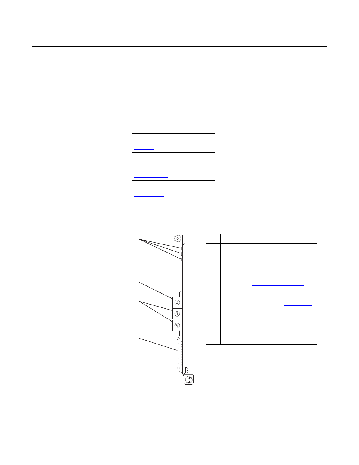
Item Part Description
➊
Status
Indicators
Three status indicators that indicate the
status of the option module and
network communication. See
Chapter 7, Troubleshooting.
➋
Data Rate
Switch
Sets the DeviceNet data rate at which
the option module communicates. See
Setting the Data Rate Switch on
page 19.
➌
Node Address
Switche s
Sets the network node address of the
option module. See Setting the Node
Address Switches on page 18.
➍
DeviceNet
Connector
A 5-pin connector for the DeviceNet
network cable. (A mating 5-pin linear
plug is supplied with the option
module to connec t to the network
cable.
Getting Started
The 20-750-DNET option module is intended for installation into a PowerFlex
750-Series drive and is used for network communication.
Top ic Pa ge
Components
Featu res
Understanding Parameter Types
Compatible Produ cts
Required Equipment 13
Safety Precautions 15
Quick Start
11
12
13
13
16
Components
Rockwell Automation Publication 750COM-UM002B-EN-P - October 2012 11
Page 12

Chapter 1 Getting Started
Features
The features of the option module include the following:
• Captive screws to secure and ground the module to the drive.
• Switches to set a node address and network data rate before applying
power to the drive—or you can disable the switches and use option
module parameters to configure these functions.
• Compatibility with the following configuration tools to configure the
option module and host drive:
– PowerFlex 20-HIM-A6 or 20-HIM-C6S HIM (Human Interface
Module) on the drive, if available
– Connected Components Workbench software, version 1.02 or later
– DriveExplorer software, version 6.01 or later
– DriveExecutive software, version 5.01 or later
• Status indicators that report the status of the option module and network
communication. They are visible when the drive cover is removed.
• Parameter-configured 32-bit Datalinks in the I/O to meet application
requirements (16 Datalinks to write data from the network to the drive,
and 16 Datalinks to read data to the network from the drive).
• Explicit Messaging and UCMM (Unconnected Message Manager)
support.
• Multiple data exchange methods, including Polled, Cyclic, and Change of
State (COS), to transmit data between the network and option module.
• Master-Slave hierarchy that can be configured to transmit data to and from
a controller on the network.
• User-defined fault actions to determine how the option module and its
connected host drive respond to the following:
– I/O messaging communication disruptions (Comm Flt Action)
– Controllers in Idle mode (Idle Flt Action)
– Explicit messaging disruptions for drive control via PCCC or the CIP
Register Object (Msg Flt Action)
• Faulted node recovery support. You can configure a device even when it is
faulted on the network if you have a configuration tool that uses faulted
node recovery and have set the Data Rate switch to position ‘3’. With this
configuration, the option module uses parameter settings stored in its
nonvolatile storage (NVS) memory for the data rate and node address
instead of using its switch settings.
• Access to any PowerFlex drive and its connected peripherals on the
network to which the option module is connected.
12 Rockwell Automation Publication 750COM-UM002B-EN-P - October 2012
Page 13

Getting Started Chapter 1
Understanding Parameter Types
The option module has two types of parameters:
• Device parameters are used to configure the option module to operate on
the network.
• Host parameters are used to configure the option module Datalink transfer
and various fault actions with the drive.
Yo u can vi ew op ti on m o du l e Device parameters and Host parameters with any of
the following drive configuration tools:
• PowerFlex 20-HIM-A6 or 20-HIM-C6S HIM—use the or
key to scroll to the drive port in which the module resides, press the
(Folders) key, and use the or key to scroll to the DEV
PARA M or H OST PARAM fo lder.
• Connected Components Workbench software—click the tab for the
option module at the bottom of the window, click the Parameters icon in
the tool bar, and click the Device or Host Parameters tab.
• DriveExplorer software—find the option module in the treeview and open
its Parameters folder.
Compatible Products
Required Equipment
• DriveExecutive software—find the option module in the treeview, expand
the module in the tree, and open its Parameters folder.
At the time of publication, the option module is compatible with the following
products:
• PowerFlex 753 drives (all firmware revisions)
• PowerFlex 755 drives (all firmware revisions)
Some of the equipment that is required for use with the option module is shipped
with the module, but some you must supply yourself.
Equipment Shipped with the Option Module
When you unpack the option module, verify that the package includes the
following:
❑ One 20-750-DNET DeviceNet Option Module
❑ One 5-pin linear DeviceNet plug
(connected to the DeviceNet connector on the option module)
❑ One Network Communication Option Module Installation Instructions,
publication 750COM-IN002
Rockwell Automation Publication 750COM-UM002B-EN-P - October 2012 13
Page 14

Chapter 1 Getting Started
User-Supplied Equipment
To install and configure the option module, you must supply the following:
❑ A small screwdriver
❑ DeviceNet cable—we recommend thin cable with an outside diameter of
6.9 mm (0.27 in.)
❑ Drive and option module configuration tool, such as the following:
– PowerFlex 20-HIM-A6 or 20-HIM-C6S HIM
– Connected Components Workbench software, version 1.02 or later
Connected Components Workbench is the recommended stand-alone
software tool for use with PowerFlex drives. You can obtain a free copy
by:
• Internet download at http://www.ab.com/support/abdrives/
webupdate/software.html
• Requesting a DVD at http://www.ab.com/onecontact/
controllers/micro800/
Your local distributor may also have copies of the DVD available.
Connected Components Workbench software cannot be used to
configure SCANport-based drives or Bulletin 160 drives.
– DriveExplorer software, version 6.01 or later
This software tool has been discontinued and is now available as
freeware at http://www.ab.com/support/abdrives/webupdate/
software.html. There are no plans to provide future updates to this tool
and the download is being provided ‘as-is’ for users that lost their
DriveExplorer CD, or need to configure legacy products not supported
by Connected Components Workbench software.
– DriveExecutive software, version 5.01 or later
A Lite version of DriveExecutive software ships with RSLogix 5000,
RSNetworx MD, FactoryTalk AssetCentre, and IntelliCENTER
software. All other versions are purchasable items:
• 9303-4DTE01ENE Drive Executive software
• 9303-4DTS01ENE DriveTools SP Suite (includes DriveExecutive
and DriveObserver software)
• 9303-4DTE2S01ENE DriveExecutive software upgrade to
DriveTools SP Suite (adds DriveObserver software)
DriveExecutive software updates (patches, and so forth) can be obtained
at http://www.ab.com/support/abdrives/webupdate/software.html
highly recommended that you periodically check for and install the latest
update.
❑ RSNetWorx for DeviceNet network configuration software, version 8.00 or
later
14 Rockwell Automation Publication 750COM-UM002B-EN-P - October 2012
. It is
Page 15
Getting Started Chapter 1
❑ Controller configuration software, such as RSLogix 5000 software, version 20.00
or earlier, or Studio 5000™ Logix Designer application, version 21.00 or later
❑ A computer communication card, such as 1784-PCD, 1784-PCID, 1784-
PCIDS, or 1770-KFD, for connection to the DeviceNet network
Safety Precautions
Please read the following safety precautions carefully.
ATTENTION: Risk of injury or death exists. The PowerFlex drive may contain high
voltages that can cause injury or death. Remove all power from the PowerFlex
drive, and then verify power has been discharged before installing or removing
an option module.
ATTENTION: Risk of injury or equipment damage exists. Only personnel familiar
with drive and power products and the associated machinery should plan or
implement the installation, startup, configuration, and subsequent maintenance
of the drive using the option module. Failure to comply may result in injury and/
or equipment damage.
ATTENTION: Risk of equipment damage exists. The option module contains
electrostatic discharge (ESD) sensitive parts that can be damaged if you do not
follow ESD control procedures. Static control precautions are required when
handling the option module. If you are unfamiliar with static control procedures,
see Guarding Against Electrostatic Damage, publication 8000-4.5.2
ATTENTION: Risk of injury or equipment damage exists. If the option module is
transmitting control I/O to the drive, the drive may fault when you reset the
option module. Determine how your drive will respond before resetting the
module.
.
ATTENTION: Risk of injury or equipment damage exists. Host Parameters 33 [Comm Flt Action], 34 - [Idle Flt Action], and 36 - [Msg Flt Action] let you
determine the action of the option module and connected drive if I/O
communication is disrupted, the controller is idle, or explicit messaging for drive
control is disrupted. By default, these parameters fault the drive. You may
configure these parameters so that the drive continues to run, however,
precautions should be taken to verify that the settings of these parameters do
not create a risk of injury or equipment damage. When commissioning the drive,
verify that your system responds correctly to various situations (for example, a
disconnected cable or a controller in idle state).
ATTENTION: Risk of injury or equipment damage exists. When a system is
configured for the first time, there may be unintended or incorrect machine
motion. Disconnect the motor from the machine or process during initial system
testing.
ATTENTION: Risk of injury or equipment damage exists. The examples in this
publication are intended solely for purposes of example. There are many
variables and requirements with any application. Rockwell Automation does not
assume responsibility or liability (to include intellectual property liability) for
actual use of the examples shown in this publication.
Rockwell Automation Publication 750COM-UM002B-EN-P - October 2012 15
Page 16

Chapter 1 Getting Started
Quick Start
This section is provided to help experienced users quickly start using the option
module. If you are unsure how to complete a step, refer to the referenced chapter.
Step Action See
1 Review the safety precautions for the option module. Throughout this manual
2 Verify that the PowerFlex drive is properly installed. PowerFlex 750-Series AC Drive
3 Install the option module.
a. Verify that the PowerFlex drive is not powered.
b. Insert the option module in drive Port 4, 5, or 6.
c. Use the captive screws to secure and ground the option module to
the drive.
d. Connect the option module to the network with a DeviceNet cable.
4 Apply power to the option module.
a. Verify that the option module is installed correctly.
The option module receives power from the drive.
b. Apply power to the drive.
The status indicators should be green. If they flash red, there is a
problem. See Chapter 7
c. Configure and verify key drive parameters.
5 Configure the option module for your application.
Set option module parameters for the following functions as required by
your application:
• Node address—only if Data Rate switch is set to position ‘3’;
otherwise use Node Address switches.
• Data rate—only if Data Rate switch is set to position ‘3’; otherwise
set this switch to position ‘0’, ‘1’, ‘2’, or ‘4’ through ‘9’ depending on the
application.
• I/O configuration
• Change of State, Cyclic or Polled I/O data exchange
• Master-Slave hierarchy
• Fault actions
6 Configure the controller to communicate with the option module.
Use the network configuration tool RSNetWorx for DeviceNet software,
and a controller configuration tool, such as RSLogix software, to configure
the master on the network to recognize the option module and drive.
7 Create a ladder logic program.
Use a controller configuration tool, such as RSLogix software, to create a
ladder logic program that enables you to do the following:
• Control the connected drive, via the option module, by using I/O.
• Monitor or configure the drive by using explicit messages.
, Troubleshooting.
Installation Instructions,
publication 750-IN001
Network Communication Option
Module Installation Instructions,
publication 750COM-IN002
Chapter 2,
Installing the Option Module
Chapter 2,
Installing the Option Module
,
Chapter 3
Configuring the Option Module
,
Chapter 4
Configuring the I/O
,
Chapter 5
Using the I/O
,
Chapter 6
Using Explicit Messaging
, and
16 Rockwell Automation Publication 750COM-UM002B-EN-P - October 2012
Page 17
Chapter 2
Installing the Option Module
This chapter provides instructions for installing the option module in a
PowerFlex 750-Series drive.
Top ic Pag e
Preparing for an Installation
Setting the Node Address Switches
Setting the Data Rate Switch
Connecting the Option Module to the Drive
Connecting the Option Module to the Network 20
Applying Power 21
Commissioning the Option Module
17
18
19
19
24
Preparing for an Installation
Before installing the option module, do the following:
• Read the DeviceNet Media Design and Installation Guide, publication
DNET-UM072
• Read the DeviceNet Starter Kit User Manual, publication DNET-
UM003.
• Verify that you have all required equipment. See Required Equipment
page 13.
ATTENTION: Risk of equipment damage exists. The option module contains
electrostatic discharge (ESD) sensitive parts that can be damaged if you do not
follow ESD control procedures. Static control precautions are required when
handling the option module. If you are unfamiliar with static control procedures,
see Guarding Against Electrostatic Damage, publication 8000-4.5.2
.
on
Rockwell Automation Publication 750COM-UM002B-EN-P - October 2012 17
Page 18
Chapter 2 Installing the Option Module
IMPORTANT
0
5
4
9
3
8
2
7
1
6
0
5
4
9
3
8
2
7
1
6
0
5
4
9
3
8
2
7
1
6
0
5
4
9
3
8
2
7
1
6
0
5
4
9
3
8
2
7
1
6
ONES
Posi tion
TENS
Posi tion
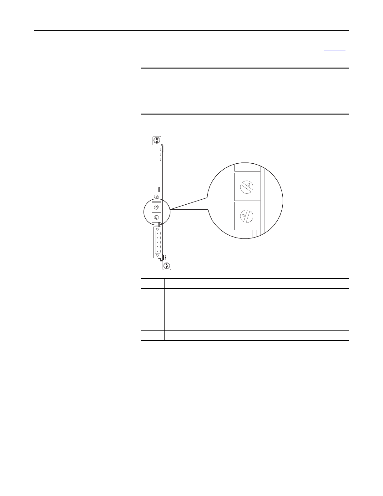
Setting the Node Address Switches
Set the option module Node Address switches (bottom two switches in Figure 1)
by rotating the switches to the desired value for each digit.
Each node on the DeviceNet net work must have a unique address. Set the node
address before power is applied because the option module uses the node
address it detects when it first receives power. To change a node address, you
must set the new value and then remove and reapply power to (or reset) the
option module, or disconnect and reconnect the DeviceNet network cable.
Figure 1 - Setting the Node Address Switches
Settings Description
0…63 Node address used by the option module if switches are enabled. The default switch setting is 63. Node
64…99 Do not use. The option module will not recognize these addresses.
The switch settings can be verified by viewing Device Parameter 08 - [Net Addr
Act] or Diagnostic Device Item number 54 (page 85
address 63 is also the default address used by all non-commissioned devices. We recommend that you do
not use this address as the final option module address.
Important: If the Data Rate switch (Figure 2
stored in Device Parameter 07 - [Net Addr Cfg] for the node address. The default setting for Device
Parameter 07 - [Net Addr Cfg] is 63. See Setting the Node Address on page 26.
) is set to position ‘3’, the option module uses the value
) with any of the following
drive configuration tools:
• PowerFlex 20-HIM-A6 or 20-HIM-C6S HIM
• Connected Components Workbench software, version 1.02 or later
• DriveExplorer software, version 6.01 or later
• DriveExecutive software, version 5.01 or later
18 Rockwell Automation Publication 750COM-UM002B-EN-P - October 2012
Page 19
Installing the Option Module Chapter 2
IMPORTANT
IMPORTANT
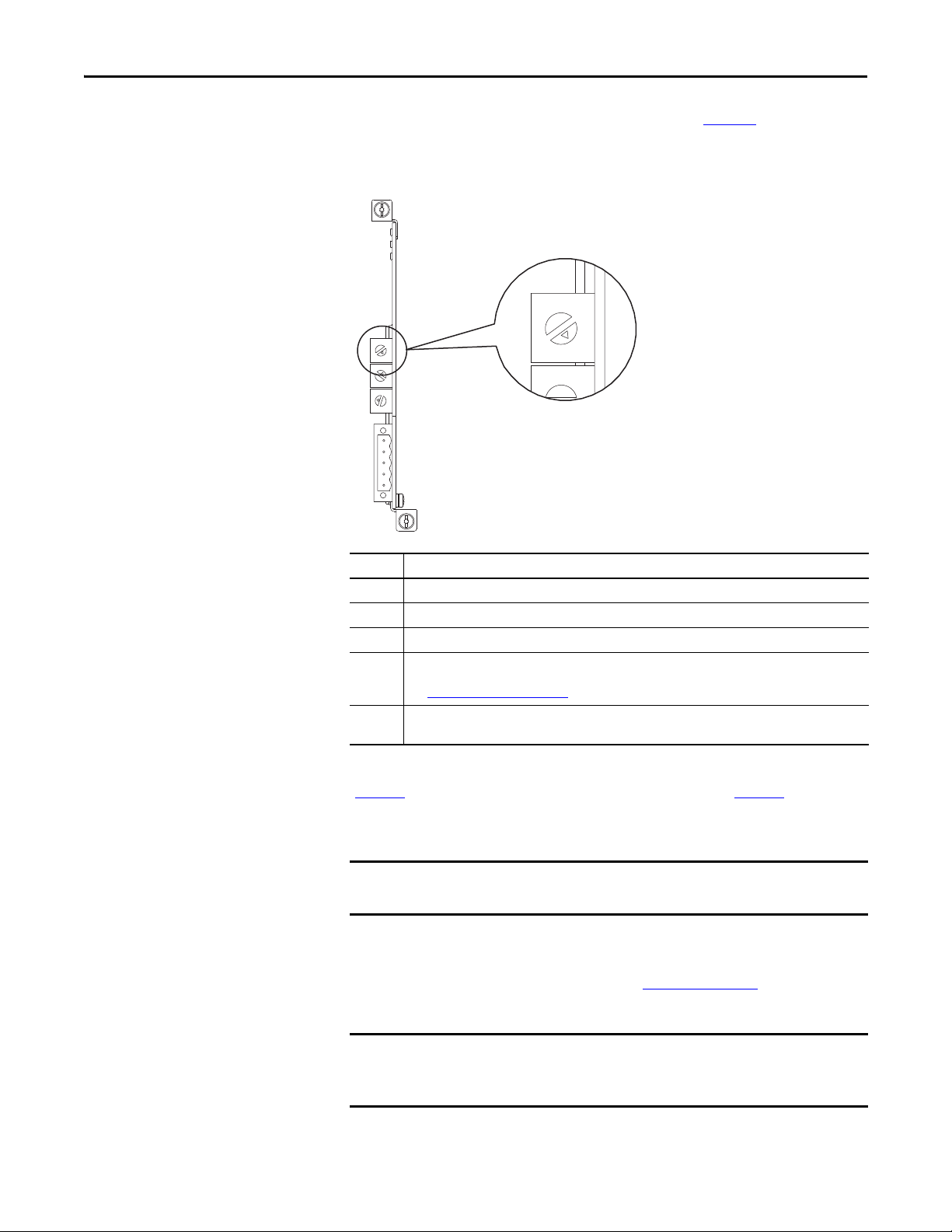
Setting the Data Rate Switch
Set the option module Data Rate switch (top switch in Figure 2) by rotating the
switch to the desired setting.
Figure 2 - Setting the Data Rate Switch
5
6
4
7
3
8
5
6
4
7
3
8
2
9
1
0
5
6
4
7
3
8
2
9
1
0
5
6
4
7
3
8
2
9
1
0
Setting Description
0 Sets the option module to the 125 Kbps data rate.
1 Sets the option module to the 250 Kbps data rate.
2 Sets the option module to the 500 Kbps data rate.
3 Sets the option module to use the data rate value stored in Device Parameter 09 - [Net Rate Cfg], and
4…9 Sets the option module to the Auto data rate—a data rate used by other network devices. Another device
sets the option module to use the node address value stored in Device Parameter 07 - [Net Addr Cfg].
See Setting the Data Rate on page 27
on the network must be set to a data rate. The default switch setting is 9.
2
9
1
0
.
Connecting the Option Module to the Drive
The switch settings can be verified by viewing Diagnostic Device Item number 53
(page 85
) with any of the drive configuration tools listed on page 18.
Remove power from the drive before installing the option module in the drive
control pod.
Install the option module in the PowerFlex 750-Series drive control pod in Port
4, 5, or 6. For more installation details, see the Network Communication Option
Module Installation Instructions, publication 750COM-IN002
, provided with
the option module.
After inserting the option module into drive Port 4, 5, or 6, make sure to
tighten the module screws to the pod mounting bracket to properly ground the
module to the drive. Torque both screws to 0.45…0.67 N•m (4.0…6.0 lb•in).
Rockwell Automation Publication 750COM-UM002B-EN-P - October 2012 19
Page 20
Chapter 2 Installing the Option Module
IMPORTANT
5
4
3
2
1
Red
White
Bare
Blue
Black
Connecting the Option Module to the Network
ATTENTION: Risk of injury or death exists. The PowerFlex drive may contain high
voltages that can cause injury or death. Remove power from the drive, and then
verify power has been discharged before connecting the option module to the
network.
1. Remove power from the drive.
2. Remove the drive cover and lift up the drive HIM bezel to its open
position to access the drive control pod.
3. Use static control precautions.
4. Connect one end of the DeviceNet cable to the network. We recommend
DeviceNet Thin cable with an outside diameter of 6.9 mm (0.27 in.).
Maximum cable length depends on data rate. For details, see Data Rate
on page 134.
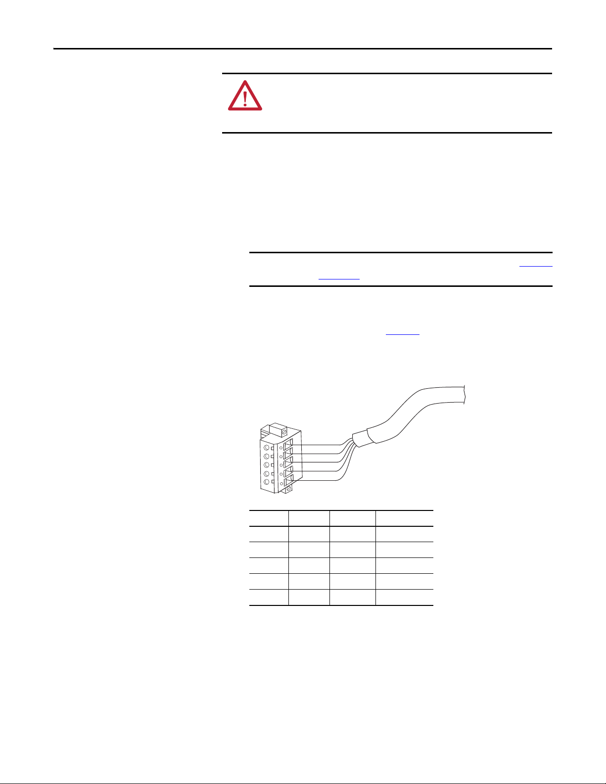
5. Route the other end of the DeviceNet cable through the bottom of the
drive, and connect the 5-pin linear plug (provided with the option
module) to the DeviceNet cable (Figure 3
needed, the replacement plug part number is 1799-DNETSCON.
Figure 3 - Connecting the 5-Pin Linear Plug to the DeviceNet Cable
). If a replacement plug is
Terminal Color Signal Function
5 Red V+ Power Supply
20 Rockwell Automation Publication 750COM-UM002B-EN-P - October 2012
4 White CAN_H Signal High
3BareSHIELDShield
2 Blue CAN_L Signal Low
1BlackV– Common
6. Insert the 5-pin linear plug into the mating option module receptacle, and
secure it with the two screws. Verify that the colors of the wires on the plug
match the color codes on the receptacle.
Page 21
Installing the Option Module Chapter 2
See Tab le 1 for
possible start-up
status indications.
Drive Control Pod
(drive shown with cover removed)
Applying Power
ATTENTION: Risk of equipment damage, injury, or death exists. Unpredictable
operation may occur if you fail to verify that parameter settings are compatible
with your application. Verify that settings are compatible with your application
before applying power to the drive.
Apply power to the drive. The option module receives its power from the drive.
When you apply power to the option module for the first time, its topmost
‘PORT’ status indicator should be steady green or flashing green after an
initialization. If it is red, there is a problem. See Chapter 7
, Troubleshooting.
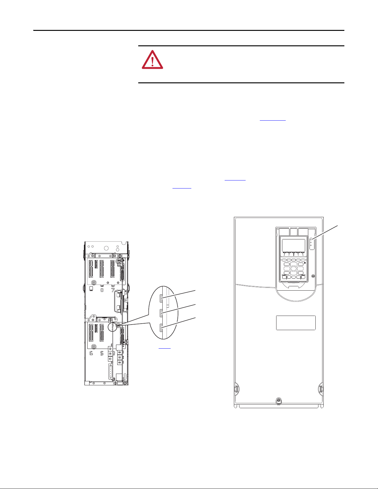
Start-Up Status Indications
After power has been applied, the drive STS (status) indicator can be viewed on
the front of the drive and the option module status indicators can be viewed with
the drive cover open or removed (Figure 4
are shown in Ta b l e 1
Figure 4 - Drive and Option Module Status Indicators
.
). Possible start-up status indications
➊
5
6
4
7
3
8
2
9
1
0
5
6
4
7
3
8
2
9
1
0
5
6
4
7
3
8
2
9
1
0
➋
➌
➍
Rockwell Automation Publication 750COM-UM002B-EN-P - October 2012 21
Page 22

Chapter 2 Installing the Option Module
Table 1 - Drive and Option Module Start-Up Status Indications
Item Name Color State Description
Drive STS Indicator
STS
➊
(Status)
PORT Green Flashing Normal operation. The option module is establishing an I/O
➋
MOD Green Flashing Normal operation. The option module is operating but is not
➌
NET A Green Flashing Normal operation. The option module is properly connected but is
➍
Green Flashing Drive ready but not running, and no faults are present.
Steady Drive running, no faults are present.
Yellow Flashing When running, a type 2 (non-configurable) alarm condition exists
– drive continues to run. When stopped, a start inhibit condition
exists and the drive cannot be started (see drive parameter 933 [Start Inhibits]).
Steady A type 1 (user configurable) alarm condition exists, but the drive
continues to run.
Red Flashing A major fault has occurred. Drive will stop. Drive cannot be started
until fault condition is cleared.
Steady A non-resettable fault has occurred.
Red/Yellow Flashing Alternately A minor fault has occurred. Use drive parameter 950 - [Minor Flt
Config] to enable. If not enabled, acts like a major fault. When
running, the drive continues to run. System is brought to a stop
under system control. The fault must be cleared to continue.
Yellow/Green Flashing Alternately When running, a type 1 alarm exists.
Green/Red Flashing Alternately Drive is firmware updating.
Option Module Status Indicators
connection to the drive. It will turn steady green or red.
Steady Normal operation. The option module is properly connected and
communicating with the drive.
transferring I/O data to a controller.
Steady Normal operation. The option module is operating and transferring
I/O data to a controller.
not communicating with any devices on the network.
Steady Normal operation. The option module is properly connected and
communicating on the network.
After verifying correct operation, swing down the drive HIM bezel to its closed
position and install the drive cover. For more details on status indicator
operation, see page 82
and page 83.
Configuring and Verifying Key Drive Parameters
The PowerFlex 750-Series drive can be separately configured for the control and
Reference functions in various combinations. For example, you could set the
drive to have its control come from a peripheral or terminal block with the
Reference coming from the network. Or you could set the drive to have its
control come from the network with the Reference coming from another
peripheral or terminal block. Or you could set the drive to have both its control
and Reference come from the network.
22 Rockwell Automation Publication 750COM-UM002B-EN-P - October 2012
Page 23
Installing the Option Module Chapter 2
The following steps in this section assume that the drive will receive the Logic
Command and Reference from the network.
1. Verify that drive Parameter 301 - [Access Level] is set to ‘1’ (Advanced) or
‘2’ (Expert) to access the required parameters in this procedure.
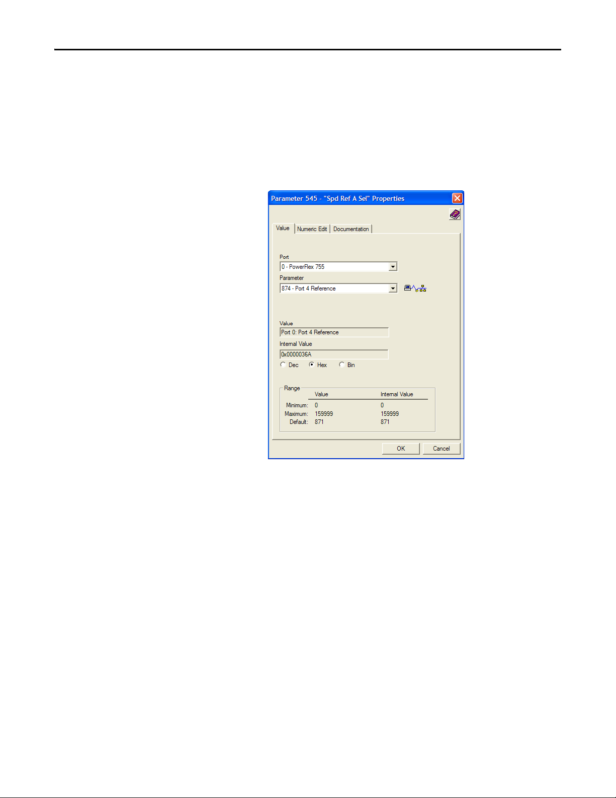
2. Use drive Parameter 545 - [Speed Ref A Sel] to set the drive speed
Reference.
a. Set the Port field to ‘0’ as shown below.
b. Set the Parameter field to point to the port (slot) in which the option
module is installed (for this example, Port 4 Reference).
The number ‘874’ in the Parameter field of the example dialog box
above is the parameter in the drive that points to the port.
3. Verify that drive Parameter 930 - [Speed Ref Source] is reporting that the
source of the Reference to the drive (Port 0) is the port in which the option
module is installed (for example, Port 4 Reference).
This ensures that any Reference commanded from the network can be
monitored by using drive Parameter 002 - [Commanded SpdRef]. If a
problem occurs, this verification step provides the diagnostic capability to
determine whether the drive/option module or the network is the cause.
4. If hard-wired discrete digital inputs are not used to control the drive, verify
that all unused digital input drive parameters are set to ‘0’ (Not Used).
Rockwell Automation Publication 750COM-UM002B-EN-P - October 2012 23
Page 24

Chapter 2 Installing the Option Module
IMPORTANT
Commissioning the Option Module
To commission the option module, you must set a unique network node address.
See the Glossary
switches, see Setting the Node Address Switches
for details about node addresses. When using the Node Address
on page 18 for details.
New settings are recognized only when power is applied to the option module
or it is reset. After you change parameter settings, cycle power or reset the
option module.
24 Rockwell Automation Publication 750COM-UM002B-EN-P - October 2012
Page 25
IMPORTANT
Chapter 3
Configuring the Option Module
This chapter provides instructions and information for setting the parameters to
configure the option module.
Top ic Pa ge
Configuration Tools
Using the PowerFlex 20-HIM-A6 or 20-HIM-C6S HIM to Access Parameters
Setting the Node Address
Setting the Data Rate 27
Setting a Master-Slave Hierarchy (Optional) 27
Selecting COS, Cyclic, or Polled Data Exchange
Setting a Fault Action 31
Resetting the Option Module 32
Restoring Option Module Parameters to Factory Defaults
Viewing the Option Module Status Using Parameters 34
Updating the Option Module Firmware 35
25
26
26
29
33
Configuration Tools
For a list of parameters, see Appendix
definitions of terms in this chapter, see the Glossary
The option module stores parameters and other information in its own
nonvolatile storage (NVS) memory. You must, therefore, access the option
module to view and edit its parameters. The following tools can be used to access
the option module parameters.
Too l Se e
PowerFlex 20-HIM-A6 or 20-HIM-C6S HIM page 26
Connected Components Workbench software,
version 1.02 or later
DriveExplorer software,
version 6.01 or later
DriveExecutive software,
version 5.01 or later
For the HIM screens shown throughout this chapter, the option module was
installed in drive Port 4. If your option module is installed in a different drive
port, that port would appear instead of Port 4.
B, Option Module Parameters. For
.
http://www.ab.com/support/abdrives/webupdate/
software.html, or online help (installed with the software)
http://www.ab.com/drives/driveexplorer, or online help
(installed with the software)
http://www.ab.com/drives/drivetools
(installed with the software)
, or online help
Rockwell Automation Publication 750COM-UM002B-EN-P - October 2012 25
Page 26

Chapter 3 Configuring the Option Module
TIP
ESC
ENTER
Stopped
0.00 Hz
AUTO
F
Edit Net Addr Cfg
63
0<<63
Using the PowerFlex 20-HIMA6 or 20-HIM-C6S HIM to
Access Parameters
Setting the Node Address
If your drive has an enhanced PowerFlex 20-HIM-A6 or 20-HIM-C6S HIM, it
can be used to access parameters in the option module.
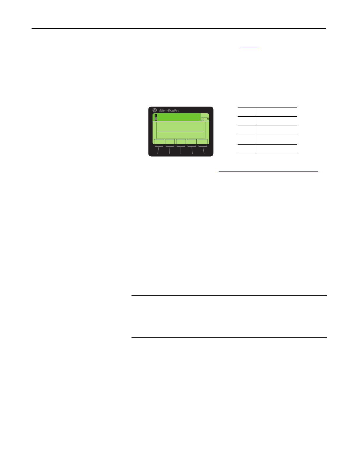
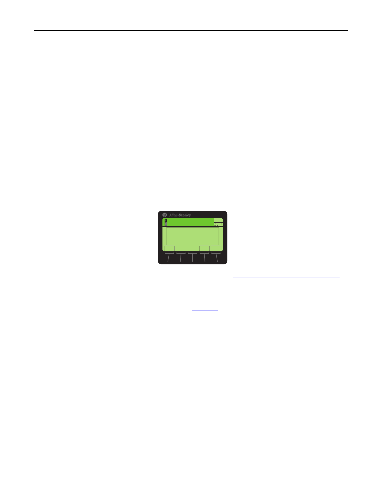
1. Display the Status screen, which is shown on HIM powerup.
2. Use the or key to scroll to the Port in which the option
module is installed.
3. Press the PAR# soft key to display the Jump to Param # entry pop-up box.
4. Use the numeric keys to enter the desired parameter number, or use the
or soft key to scroll to the desired parameter number.
For details on viewing and editing parameters, see the PowerFlex 20-HIM-A6/C6S HIM (Human Interface Module) User Manual, publication 20HIM-
UM001.
When the option module Data Rate switch (Figure 2) is set to position ‘3’
(Program), the value of Device Parameter 07 - [Net Addr Cfg] determines the
node address. When the Data Rate switch is set to any other position, the Node
Address switch settings determine the node address.
We recommend that you do not use node address 63 because all new devices
on the network use this address as the default address. Also, node address 63 is
used for Automatic Device Recovery (ADR).
1. Set the value of Device Parameter 07 - [Net Addr Cfg] to a unique node
address.
2. Reset the option module; see Resetting the Option Module
The NET A status indicator will be steady green or flashing green if the
node address is correctly configured, and the option module is connected
to an operational network.
on page 32.
26 Rockwell Automation Publication 750COM-UM002B-EN-P - October 2012
Page 27
Configuring the Option Module Chapter 3
Value Data Rate
0 125 Kbps
1 250 Kbps
2 500 Kbps
3 Autobaud (default)
ESC
ENTER
Stopped
0.00 Hz
AUTO
F
▲▼
Edit Net Rate Cfg
Autobaud 3
0<<3
IMPORTANT
Setting the Data Rate
Setting a Master-Slave Hierarchy (Optional)
When the option module Data Rate switch (Figure 2) is set to position ‘3’
(Program), the value of Device Parameter 09 - [Net Rate Cfg] determines the
data rate. The default setting for this parameter, ‘3’ (Autobaud), will detect the
data rate used on the network if another device is setting the data rate. Your
application may require a different setting.
1. Set the value of Device Parameter 09 - [Net Rate Cfg] to the data rate at
which your network is operating.
2. Reset the option module; see Resetting the Option Module
This procedure is only required if Datalinks are used to write or read data of the
drive or its connected peripherals. A hierarchy determines the type of device with
which the option module exchanges data. In a Master-Slave hierarchy, the option
module exchanges data with a master, such as a scanner (1756-DNB, 1771-SDN,
1747-SDN, and so forth).
on page 32.
Enable Datalinks To Write Data
The controller output image (controller outputs-to-drive) can have 0 to 16
additional 32-bit parameters (Datalinks). The quantity of additional parameters
is configured using Device Parameter 02 - [DLs From Net Cfg].
Always use the Datalink parameters in consecutive numerical order, starting
with the first parameter. For example, use Host Parameters 01, 02, and 03 to
configure three Datalinks to write data. Otherwise, the network I/O connection
Host Parameters 01 - [DL From Net 01] through 16 - [DL From Net 16]
control which parameters in the drive, option module, or any other connected
peripheral receive the values from the network. You can use the PowerFlex 20HIM-A6 or 20-HIM-C6S HIM, or another drive configuration tool such as
Connected Components Workbench, DriveExplorer, or DriveExecutive software
to select the drive or peripheral by port number and the parameter by name. As
an alternate method, the parameter value can be set manually by number using
this formula:
Rockwell Automation Publication 750COM-UM002B-EN-P - October 2012 27
From Net Parameter Value = (10000 * port number) + (Destination Parameter Number)
will be larger than necessary, which needlessly increases controller response
time and memory usage.
Page 28
Chapter 3 Configuring the Option Module
IMPORTANT
ESC
ENTER
Stopped
0.00 Hz
AUTO
F
Edit DLs From Net Cfg
0
0<<16
For example, suppose you want to use Host Parameter 01 - [DL From Net 01] to
write to Parameter 03 of an optional encoder module plugged into drive Port 5.
Using the formula, the value for Host Parameter 01 - [DL From Net 01] would
be (10000 * 5) + (3) = 50003.
Follow these steps to enable Datalinks to write data.
1. Set the value of Device Parameter 02 - [DLs From Net Cfg] to the
number of contiguous controller-to-drive Datalinks that are to be
included in the network I/O connection.
2. Reset the option module; see Resetting the Option Module
3. Since the Logic Command and Reference are always used in the option
module, configure the parameters in the drive to accept the Logic
Command and Reference from the option module.
When using the controller for speed reference via the option module, set
two fields in drive Parameter 545 - [Speed Ref A Sel].
a. Set the Port field for the drive (for example, 0 - PowerFlex 755).
b. Set the Parameter field to point to the port in which the option module
is installed (for this example, Port 4 Reference).
Also, verify that the mask parameters in the drive (for example,
Parameter 324 - [Logic Mask]) are configured to receive the desired
logic from the option module. See the drive documentation for details.
After the above steps are complete, the option module is ready to receive input
data and transfer status data to the master (controller). Next, configure the
controller to recognize and transmit I/O to the option module. See Chapter 4
Configuring the I/O.
on page 32.
Enable Datalinks To Read Data
,
The controller input image (drive-to-controller inputs) can have 0 to 16
additional 32-bit parameters (Datalinks). The quantity of additional parameters
is configured using Device Parameter 04 - [DLs To Net Cfg].
Always use the Datalink parameters in consecutive numerical order, starting
with the first parameter. For example, use Host Parameters 17, 18, 19, 20, and
21 to configure five Datalinks to read data. Otherwise, the network I/O
connection will be larger than necessary, which needlessly increases controller
response time and memory usage.
28 Rockwell Automation Publication 750COM-UM002B-EN-P - October 2012
Page 29
Configuring the Option Module Chapter 3
ESC
ENTER
Stopped
0.00 Hz
AUTO
F
Edit DLs To Net Cfg
0
0<<16
Host Parameters 17 - [DL To Net 01] through 32 - [DL To Net 16] configure
which parameters in the drive, option module, or any other connected peripheral
send the values to the network. You can use the PowerFlex 20-HIM-A6 or 20HIM-C6S HIM, or another drive configuration tool such as Connected
Components Workbench, DriveExplorer, or DriveExecutive software to select
the drive or peripheral by port number and the parameter by name. As an
alternate method, the parameter value can be set manually by number using this
formula:
To Net Parameter Value = (10000 * Port Number) + (Origination Parameter Number)
For example, suppose you want to use Host Parameter 17 - [DL To Net 01] to
read Parameter 2 of an optional I/O module plugged into drive Port 6. Using the
formula, the value for Host Parameter 17 - [DL To Net 01] would be (10000 * 6)
+ (2) = 60002.
Follow these steps to enable Datalinks to read data.
1. Set the value of Device Parameter 04 - [DLs To Net Cfg] to the number
of contiguous drive-to-controller Datalinks that are to be included in the
network I/O connection.
Selecting COS, Cyclic, or Polled Data Exchange
2. Reset the option module; see Resetting the Option Module
The option module is configured to send output data to the master (controller).
You must now configure the controller to recognize and transmit I/O to the
option module. See Chapter 4
The data exchange is the method that the option module uses to exchange data
on the DeviceNet network. Polled is the default and is recommended—unless
one of the other following data exchanges, which the adapter supports, is more
appropriate for your application:
• COS (Change of State) • Polled and COS
• Cyclic • Polled and Cyclic
• Polled
If ‘Polled and COS’ or ‘Polled and Cyclic’ is used, the option module transmits
and receives the I/O from the polled messages. It transmits only a Logic Status
and Feedback in COS or Cyclic messages. Other data is transmitted in Polled
messages.
, Configuring the I/O.
on page 32.
Cyclic and Polled data exchanges are configured in the scanner, so you only need
to set the I/O configuration in the option module. COS data exchange must be
Rockwell Automation Publication 750COM-UM002B-EN-P - October 2012 29
Page 30
Chapter 3 Configuring the Option Module
TIP
Valu e Des cript ion
0 Ignore this logic bit. (Default)
1 Use this logic bit.
ES C ENTER
Stopped
0.00 Hz
AUTO
F
Edit COS Status Mask
xxxx xxxx xxxx xxxx
ESC
ENTER
Stopped
0.00 Hz
AUTO
F
Edit COS Fdbk Change
0.000
0.000 << 3.40282E38
EXP
configured in both the option module and the scanner. You need to set the I/O
configuration and COS parameters in the option module.
Set Up the COS (Change of State) Data Exchange (Optional)
Set Device Parameter 11 - [COS Status Mask] for the bits in the Logic Status
word that should be checked for changes. For the Logic Status bit definitions, see
Appendix
D or the drive documentation.
The 20-HIM-A6 or 20-HIM-C6S HIM shows 32-bit Bit-type parameters in two
16-bit sets. By default, the lower 16-bit set (bits 0…15) is shown. To view the
upper 16-bit set (bits 16…31), press the UPPER soft key. To view the lower 16bit set again, press the LOWER soft key. To select each bit position, use the
or soft key or the or numeric key.
1. Edit any of the bits as required.
a. Press the EDIT soft key to display the Edit COS Status Mask screen.
b. To toggle a bit between 0 or 1, press any numeric key—except the
or key.
2. Set Device Parameter 12 - [COS Fdbk Change] for the amount of change
to the Feedback that is required to trigger a Change of State message.
The option module is now configured for COS data exchange. You must
configure the scanner to allocate it using COS (Chapter 4
, Configuring the I/O).
30 Rockwell Automation Publication 750COM-UM002B-EN-P - October 2012
Page 31

Configuring the Option Module Chapter 3
ESC
ENTER
Stopped
0.00 Hz
AUTO
F
▲▼
Edit Comm Flt Action
Fault 0
0<<4
ESC
ENTER
Stopped
0.00 Hz
AUTO
F
▲▼
Edit Idle Flt Action
Fault 0
0<<4
ESC
ENTER
Stopped
0.00 Hz
AUTO
F
▲▼
Edit Msg Flt Action
Fault 0
0<<4
Setting a Fault Action
By default, when communication is disrupted (for example, the network cable is
disconnected), the controller is idle (in program mode or faulted), or explicit
messaging for drive control is disrupted, the drive responds by faulting if it is using
I/O from the network. You can configure a different response to these faults:
• Disrupted I/O communication by using Host Parameter 33 - [Comm Flt
Action].
• An idle controller by using Host Parameter 34 - [Idle Flt Action].
• Disrupted explicit messaging for drive control via PCCC or the CIP
Register Object by using Host Parameter 36 - [Msg Flt Action].
ATTENTION: Risk of injury or equipment damage exists. Host Parameters 33 [Comm Flt Action], 34 - [Idle Flt Action], and 36 - [Msg Flt Action] let you
determine the action of the option module and connected drive if communication
is disrupted, the controller is idle, or explicit messaging for drive control is
disrupted. By default, these parameters fault the drive. You may configure these
parameters so that the drive continues to run, however, precautions should be
taken to verify that the settings of these parameters do not create a risk of injury or
equipment damage. When commissioning the drive, verify that your system
responds correctly to various situations (for example, a disconnected network
cable, controller in idle state, or explicit message control disruption).
Changing the Fault Action
Set the values of Host Parameters 33 - [Comm Flt Action], 34 - [Idle Flt
Action], and 36 - [Msg Flt Action] to an action that meets your application
requirements.
Value Action Description
0 Fault The drive is faulted and stopped. (Default)
1 Stop The drive is stopped, but not faulted.
2 Zero Data The drive is sent ‘0’ values for data. This does not command a stop.
3 Hold Last The drive continues in its present state.
4 Send Flt Cfg The drive is sent the data that you set in the fault configuration parameters (Host
Parameters 37 - [Flt Cfg Logic], 38 - [Flt Cfg Ref], and 39 - [Flt Cfg DL 01] through
54 - [Flt Cfg DL 16]).
Figure 5 - Edit Fault Action HIM Screens
Changes to these parameters take effect immediately. A reset is not required.
If communication is disrupted and then is re-established, the drive will
automatically receive commands over the network again.
Rockwell Automation Publication 750COM-UM002B-EN-P - October 2012 31
Page 32

Chapter 3 Configuring the Option Module
Value D escripti on
0Ready (Default)
1 Reset Module
2Set Defaults
ESC
ENTER
Stopped
0.00 Hz
AUTO
F
▲▼
Edit Reset Module
Ready 0
0<<2
Setting the Fault Configuration Parameters
When setting Host Parameter 33 - [Comm Flt Action], 34 - [Idle Flt Action]
or 36 - [Msg Flt Action] to ‘Send Flt Cfg’, the values in the following parameters
are sent to the drive after a communication fault, idle fault, and/or explicit
messaging for drive control fault occurs. You must set these parameters to values
required by your application.
Option Module Host Parameter Description
Parameter 37 - [Flt Cfg Logic] A 32-bit value sent to the drive for Logic Command.
Parameter 38 - [Flt Cfg Ref] A 32-bit REAL (floating point) value sent to the drive for Reference.
Parameter 39 - [Flt Cfg DL 01]
through
Parameter 54 - [Flt Cfg DL 16]
Changes to these parameters take effect immediately. A reset is not required.
A 32-bit integer value sent to the drive for a Datalink. If the destination of the
datalink is a REAL (floating point) parameter, you must convert the desired
value to the binary representation of the REAL value. (An internet search of
‘hex to float’ provides a link to a tool to do this conversion.)
Resetting the Option Module
Changes to switch settings and some option module parameters require you to
reset the option module before the new settings take effect. You can reset the
option module by power cycling the drive or by using Device Parameter 14 -
[Reset Module].
ATTENTION: Risk of injury or equipment damage exists. If the option module is
transmitting control I/O to the drive, the drive may fault when you reset the
option module. Determine how your drive will respond before resetting the
option module.
Set Device Parameter 14 - [Reset Module] to ‘1’ (Reset Module).
When you enter ‘1’ (Reset Module), the option module will be immediately reset.
An alternate method to reset the module is by power cycling the drive. When you
enter ‘2’ (Set Defaults), the option module will set all of its Device and Host
parameters to their factory default values. (This is the same as pressing the ALL
soft key when using the MEMORY folder method described in Restoring Option
Module Parameters to Factory Defaults on page 33.)
32 Rockwell Automation Publication 750COM-UM002B-EN-P - October 2012
Page 33

Configuring the Option Module Chapter 3
IMPORTANT
TIP
Stopped
0.00 Hz
AUTO
Host Drive
240V 4.2A
Rev 3.002 Ser. A
ESC REF TEXT
F
PAR#
When performing a Set Defaults, the drive may detect a conflict and then not
allow this function to occur. If this happens, first resolve the conflict and then
repeat a Set Defaults action. Common reasons for a conflict include the drive
running or a controller in Run mode.
After performing a Set Defaults, you must enter ‘1’ (Reset Module) or power
cycle the drive so that the new values take effect. Thereafter, this parameter
will be restored to a value of ‘0’ (Ready).
If your application allows, you can also reset the option module by cycling
power to the drive (resetting the drive) or by using the HIM’s Reset Device
function located in the drive’s DIAGNOSTIC folder.
Restoring Option Module Parameters to Factory Defaults
As an alternate reset method, you can restore the option module parameters by
using a MEMORY folder menu item instead of using Device Parameter 14 -
[Reset Module] described in Resetting the Option Module
MEMORY folder method provides two ways to restore the option module
Device and Host parameters:
• ALL—restores ALL option module Device and Host parameters to their
factory default values.
• MOST—restores MOST option module Device and Host parameters—
except the following which are used for network setup:
– Device Parameter 07 - [Net Addr Cfg]
– Device Parameter 09 - [Net Rate Cfg]
Follow these steps to restore option module Device and Host parameters to their
factory default values.
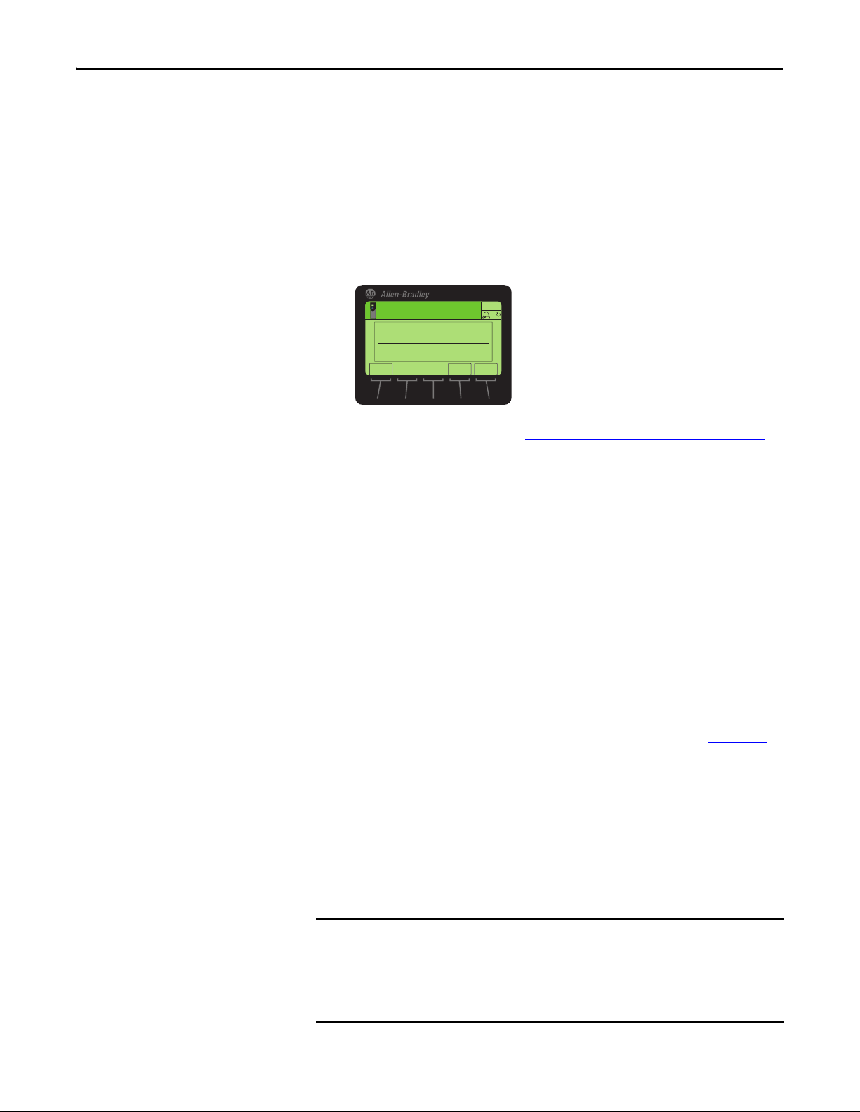
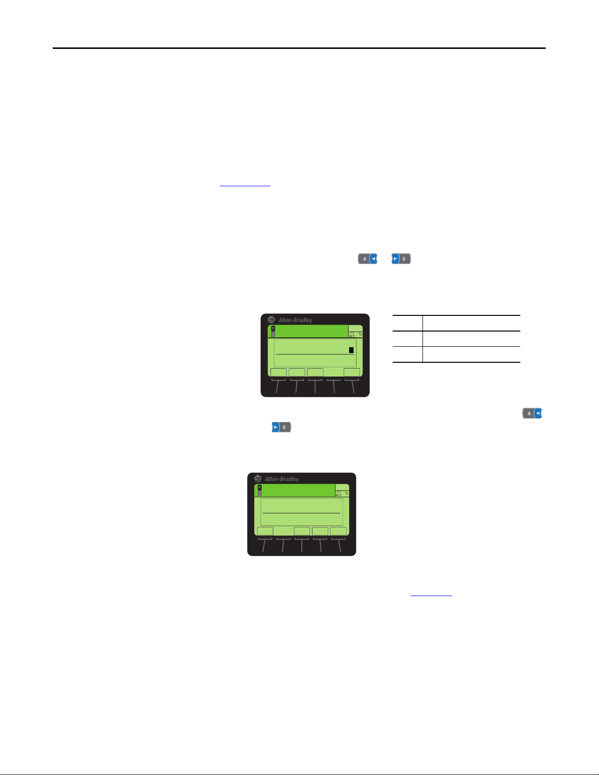
1. Access the Status screen, which is displayed on HIM powerup.
00
on page 32. The
2. Use the or key to scroll to the Port in which the option
module is installed.
3. Press the key to display its last-viewed folder.
4. Use the or key to scroll to the MEMORY folder.
5. Use the or key to select Set Defaults.
6. Press the (Enter) key to display the Set Defaults pop-up box.
Rockwell Automation Publication 750COM-UM002B-EN-P - October 2012 33
Page 34

Chapter 3 Configuring the Option Module
IMPORTANT
7. Press the (Enter) key again to display the warning pop-up box to
reset Device and Host parameters to their factory default values.
8. Press the MOST soft key to restore MOST Device and Host parameters to
factory defaults, or press the ALL soft key to restore ALL parameters. Or
press the ESC soft key to cancel.
When performing a Set Defaults, the drive may detect a conflict and
then not allow this function to occur. If this happens, first resolve the
conflict and then repeat this Set Defaults procedure. Common reasons
for a conflict include he drive running or a controller in Run mode.
9. Reset the option module using Device Parameter 14 - [Reset Module] or
by cycling power to the drive so that the restored parameters take effect.
Viewing the Option Module Status Using Parameters
The following parameters provide information about the status of the option
module. You can view these parameters at any time.
Option Module
Device Parameter
03 - [DLs From Net Act] The number of controller-to-drive Datalinks that are included in the network I/O
05 - [DLs To Net Act] The number of drive-to-controller Datalinks that are included in the network I/O
06 - [Net Addr Src] Displays the source from which the option module node address is taken, which can
08 - [Net Addr Act] The node address used by the option module, which can be one of the following:
10 - [Net Rate Act] The data rate used by the Option Module. This will be one of the following:
Description
connection (controller outputs).
connection (controller inputs).
be one of the following:
• ‘0’ (Switches)
• ‘1’ (Parameters)
• The address set with the Node Address switches (Figure 1
• The value of Device Parameter 07 - [Net Addr Cfg].
• An old address from the switches or parameter. (If either has been changed, but
the option module has not been reset, the new address will not be in effect.)
• The data rate set by the data rate switch (Figure 2
• The value of Device Parameter 09 - [Net Rate Cfg].
• An old data rate of the switch or parameter. (If either has been changed, but the
option module has not been reset, the new data rate will not be in effect.)
).
).
34 Rockwell Automation Publication 750COM-UM002B-EN-P - October 2012
Page 35

Configuring the Option Module Chapter 3
Updating the Option Module Firmware
The option module firmware can be updated over the network or serially through
a direct connection from a computer to the drive using a 1203-USB or 1203-SSS
serial converter.
When updating firmware over the network, you can use the Allen-Bradley
ControlFLASH software tool, the built-in update capability of DriveExplorer
Lite or Full software, or the built-in update capability of DriveExecutive
software.
When updating firmware through a direct serial connection from a computer to a
drive, you can use the same Allen-Bradley software tools described above, or you
can use HyperTerminal software set to the X-modem protocol.
To obtain a firmware update for this option module, go to http://www.ab.com/
support/abdrives/webupdate. This site contains all firmware update files and
associated Release Notes that describe the following items:
• Firmware update enhancements and anomalies
• How to determine the existing firmware revision
• How to update the firmware using DriveExplorer, DriveExecutive,
ControlFLASH, or HyperTerminal software
Rockwell Automation Publication 750COM-UM002B-EN-P - October 2012 35
Page 36

Chapter 3 Configuring the Option Module
Notes:
36 Rockwell Automation Publication 750COM-UM002B-EN-P - October 2012
Page 37

IMPORTANT
Chapter 4
Configuring the I/O
This chapter provides instructions on how to configure a Rockwell Automation
ControlLogix controller to communicate with the option module and connected
PowerFlex drive.
Top ic Pa ge
Using RSLinx Classic Software
ControlLogix Controller Example
Because the option module and PowerFlex 750-Series drive are 32-bit devices,
the ControlLogix controller (also a 32-bit device) is used for example purposes
in this chapter and throughout this manual. To simplify configuration and
ladder logic programs, and to maximize drive performance, we recommend
using only a 32-bit platform Logix controller with this option module and
PowerFlex 750-Series drive. If you must use a 16-bit controller (PLC-5, SLC 500,
or MicroLogix 1100/1400), we recommend using a 20-COMM-D adapter and
20-750-20COMM or 20-750-20COMM-F1 Communication Carrier Card installed
in drive Port 4, 5 or 6. In this case, go to the Rockwell Automation Technical
Support Knowledgebase website at www.rockwellautomation.com/
knowledgebase for details to configure and use the I/O, and configure explicit
messaging.
37
38
Using RSLinx Classic Software
Rockwell Automation Publication 750COM-UM002B-EN-P - October 2012 37
RSLinx Classic software, in all its variations (Lite, Gateway, OEM, and so forth), is
used to provide a communication link between the computer, network, and
controller. RSLinx Classic software requires its network-specific driver to be
configured before communication is established with network devices. To
configure the RSLinx driver, follow this procedure.
1. Start RSLinx Classic software.
2. From the Communications menu, choose Configure Drivers to display the
Configure Drivers dialog box.
3. From the Available Driver Types pull-down menu, choose DeviceNet
Drivers.
4. Click Add New to display the DeviceNet Driver Selection dialog box.
5. In the Available DeviceNet Drivers list, choose the computer connection
adapter (1784-PCD, 1784-PCID, 1784-PCIDS, or 1770-KFD) being
Page 38

Chapter 4 Configuring the I/O
Node 0
ControlLogix Controller
with 1756-DNB Scanner
Node 1
PowerFlex 750-Series Drive
(with 20-750-DNET Option Module)
Node 62
Computer with
DeviceNet Connection
DeviceNet Network
used to connect your computer to the network, and click Select to display
the Driver Configuration dialog box.
6. Configure the driver for your computer and network settings and click
OK.
The Configure Drivers dialog box reports the progress of the
configuration.
7. When the Add New RSLinx Driver dialog box appears, type a name (if
desired) and click OK.
The Configure Drivers dialog box reappears with the new driver in the
Configured Drivers list.
ControlLogix Controller Example
8. Click Close to close the Configure Drivers dialog box.
9. Keep RSLinx software running and verify that your computer recognizes
the drive.
a. From the Communications menu, choose RSWho.
b. In the menu tree, click ‘+’ next to the DeviceNet driver.
After the option module is configured, the drive and option module will be a
single node on the network. This section provides the steps needed to configure a
simple DeviceNet network (see Figure 6
ControlLogix controller with 1756-DNB scanner to communicate with a drive
using Logic Command/Status, Reference/Feedback, and 32 Datalinks (16 to
read and 16 to write) over the network.
Figure 6 - Example ControlLogix Controller DeviceNet Network
). In our example, we will configure a
38 Rockwell Automation Publication 750COM-UM002B-EN-P - October 2012
Page 39

Configuring the I/O Chapter 4
Adding the Scanner to the I/O Configuration
To establish communication between the controller and option module over the
network, you must first add the ControlLogix controller and its scanner to the
I/O configuration.
1. Start RSLogix 5000 software.
2. From the File menu, choose New to display the New Controller dialog
box.
a. Choose the appropriate choices for the fields in the dialog box to match
your application.
b. Click OK.
The RSLogix 5000 dialog box reappears with the treeview in the left
pane.
3. In the treeview, right-click the I/O Configuration folder and choose New
Module.
The Select Module dialog box appears.
4. Expand the Communications group to display all of the available
communication modules.
5. In the list, select the DeviceNet scanner used by your controller.
Rockwell Automation Publication 750COM-UM002B-EN-P - October 2012 39
Page 40

Chapter 4 Configuring the I/O
In this example, we use a 1756-DNB DeviceNet Scanner, so the 1756DNB option is selected.
6. Click OK.
7. In the Select Major Revision pop-up dialog box, select the major revision
of its firmware.
8. Click OK.
The scanner’s New Module dialog box appears.
9. Edit the following:
Box Setting
Name A name to identify the scanner.
Description Optional – description of the scanner.
Node The node address of the DeviceNet scanner.
Slot The slot of the DeviceNet scanner in the rack.
Revision The minor revision of the firmware in the scanner. (You already set the major revision by
Electro nic
Keying
Input Size The size of the input data for the DeviceNet scanner. We recommend using the default
Output Size The size of the output data for the DeviceNet scanner. We recommend using the default
Status Size The size of the status data for the DeviceNet scanner. We recommend using the default
Open Module
Properties
selecting the scanner series in step 7.)
Compatible Keying. The ‘Compatible Keying’ setting for Electronic Keying verifies that
the physical module is consistent with the software configuration before the controller
and scanner make a connection. Therefore, be sure that you have set the correct revision
in this dialog box. See the online Help for additional information on this and other
Electronic Keying settings. If keying is not required, select ‘Disable Keying’. Disable Keying
is recommended.
value of 124.
value of 123.
value of 32.
When this box is checked, clicking OK opens additional module properties dialog boxes to
further configure the scanner. When unchecked, clicking OK closes the scanner’s New
Module dialog box. For this example, uncheck this box.
10. Click OK.
The scanner is now configured for the DeviceNet network, added to the
RSLogix 5000 project, and appears in the I/O Configuration folder.
40 Rockwell Automation Publication 750COM-UM002B-EN-P - October 2012
Page 41

Configuring the I/O Chapter 4
In our example, a 1756-DNB scanner appears under the I/O
Configuration folder with its assigned name. For convenience, keep the
project open. Later in this chapter the project will need to be downloaded
to the controller.
Using RSNetWorx for DeviceNet Software to Configure and Save the I/O to the Scanner
After adding the scanner to the I/O configuration, you now must configure and
save the I/O to the scanner.
1. Start RSNetWorx for DeviceNet software.
2. From the File menu, choose New to display the New File dialog box.
3. Select DeviceNet Configuration as the network configuration type.
4. Click OK.
5. From the Network menu, choose Online to display the Browse for
Network dialog box.
6. Expand the communication path from your computer to the DeviceNet
scanner.
The following dialog box shows our example navigating to devices on a
DeviceNet network. Depending on the communication link you are using ,
the navigation path may be different.
Rockwell Automation Publication 750COM-UM002B-EN-P - October 2012 41
Page 42

Chapter 4 Configuring the I/O
7. Click OK after selecting a valid path to the DeviceNet network (for this
example, A, DeviceNet).
If a message box appears about uploading or downloading information,
click OK.
As the selected DeviceNet path is browsed, RSNetWorx for DeviceNet
software creates a graph view window that shows a graphical
representation of the devices on the network.
If the icon for the drive (for this example, PowerFlex 755) on the network
appears as Unrecognized Device, use RSNetWorx for DeviceNet software
to create the PowerFlex 750-Series drive EDS file.
The EDS file for a PowerFlex 750-Series drive differs from EDS files for all
other PowerFlex 7-Class drives in that the file does not contain any drive
or peripheral parameters. Therefore, when the EDS file is being created for
a PowerFlex 750-Series drive, no parameters are uploaded and there is no
Parameters tab, which normally appears on the Drive Properties screen.
8. Either create the EDS file by uploading it from the online device on the
network or download the EDS file from the Rockwell Automation website.
42 Rockwell Automation Publication 750COM-UM002B-EN-P - October 2012
Page 43

Configuring the I/O Chapter 4
Create the EDS File from Online Device On the Network
a. Right-click the Unrecognized Device icon and select Register Device in
the menu. The EDS Wizard appears.
b. Click Next to start creating the EDS file.
c. Select Create an EDS file.
d. Click Next.
If the EDS file is already downloaded and resides on your computer,
select ‘Register an EDS file’ and click Next. Then follow the screen
prompts and disregard the remaining steps (e through m) in this
procedure.
e. Enter a description (if desired).
f. Click Next.
g. Check the Polled box.
h. Enter ‘8’ into the Input Size and Output Size boxes (which accounts for
just the basic I/O).
i. Click Next.
RSNetWorx for DeviceNet software will upload the EDS file from the
drive.
j. Click Next to display the icon options for the node.
We recommend using the icon for the PowerFlex 750-Series drive. You
can change icons by clicking Change icon.
k. Click Next to view a summary.
l. Click Next again to accept it.
m. Click Finish to finish creating the EDS file.
A new icon represents your PowerFlex 750-Series drive and
communications option module in the RSNetWorx for DeviceNet
graph view window.
Download the EDS File from the Internet Web Site
a. Go to the website http://www.rockwellautomation.com/resources/eds.
Rockwell Automation Publication 750COM-UM002B-EN-P - October 2012 43
Page 44

Chapter 4 Configuring the I/O
b. On the website search screen in the Network entry field, enter the type
of network (for this example, DeviceNet), which enables the use of the
other search fields.
c. In the Keyword entry field, enter the type of PowerFlex 750-Series drive
(for this example, PowerFlex 755), noting that this field is space
sensitive.
d. Click Search.
Due to the large number of EDS files, this search may take seconds or
up to several minutes.
e. On the search results screen in the Details & Download Column, click
the ‘Download’ hyperlink for the EDS file.
f. Click Save on the File Download screen to save the EDS file to an
appropriate location on your computer.
g. Launch the EDS Hardware Installation Tool by clicking on the
Microsoft Windows Start button and choose Programs > Rockwell
Software > RSLinx Tools > EDS Hardware Installation Tool.
Then follow the screen prompts to add the EDS file for use with your
project.
h. Reboot the computer and repeat steps 1 through 7 at the beginning of
this subsection.
The Unrecognized Device icon in the RSNetWorx for DeviceNet
graph view window in step 7 should have been replaced by a drive icon
(for this example, the icon for a PowerFlex 755 drive).
9. In the graph view window, right-click the 1756-DNB icon and choose
Properties to display its properties dialog box.
10. Click the Module tab to display the Scanner Configuration dialog box.
11. Click Upload to upload the 1756-DNB scanner configuration to the
RSNetWorx for DeviceNet project and display the 1756-DNB Module
Tab di al o g bo x.
44 Rockwell Automation Publication 750COM-UM002B-EN-P - October 2012
Page 45

TIP
Configuring the I/O Chapter 4
12. Edit the following:
Box Setting
Interscan Delay Sets the scanner time delay between consecutive I/O scans on the network. For this
example, we recommend using the default setting of 10 milliseconds.
TIP: When numerous drives are on the network and the drives are faulting on a Comm
Loss, increasing this value may help.
Foreground… Sets the ratio of foreground to background polls. For this example, we recommend using
the default setting of 2.
Slot Sets the slot location in which the scanner is installed. For this example, Slot 3 is
selected.
13. Click Apply.
14. Click the Scanlist tab to begin the drive I/O configuration.
The Available Devices left box shows devices that are presently on the
DeviceNet network but are not yet configured. The Scanlist right box
shows devices that are presently on the DeviceNet network and are
configured.
The Automap on Add box is checked by default and allows RSNetWorx
for DeviceNet software to automatically map the drive I/O into the
scanner in the next available registers. The mapping is based on the
minimum I/O requirements (8 bytes for input and 8 bytes for output)
that the scanner obtains from the drive EDS file.
15. For this example, uncheck Automap on Add.
Rockwell Automation Publication 750COM-UM002B-EN-P - October 2012 45
Page 46

Chapter 4 Configuring the I/O
16. Select the PowerFlex 755 drive in the Available Devices box and click > to
move it to the Scanlist window.
Checkbox Description
Node Active Activates/deac tivates the scanlist in the 1756-DNB scanner for the selected device. For
Device Type Electronic Key checkboxes select how specific the device in the scanlist must be for the
Ven dor
Product Code
Major Revision
this example, keep the box checked.
1756-DNB scanner to match its compatibility for I/O operation. The more boxes that are
checked, the more specific the device must be to operate. For this example, leave the
default boxes (Device Type, Vendor, and Product Code) checked.
17. Click Edit I/O Parameters to display the Edit I/O Parameters dialog box
for the PowerFlex 755 drive used in this example.
a. Select the type or types of data exchange (Polled, Change of State, and/
or Cyclic).
For this example, Polled was selected, which we recommend.
b. Enter the number of bytes that are required for your I/O in the Input
Size and Output Size boxes.
For the example in this manual, all 16 [DL From Net xx] and all 16
[DL To Net xx] are used, resulting in an Input Size of ‘72’ and an
Output Size of ‘72’. To determine the byte sizes for your application,
46 Rockwell Automation Publication 750COM-UM002B-EN-P - October 2012
Page 47

Configuring the I/O Chapter 4
either view option module Diagnostic Items 7 (Input Size) and 8
(Output Size) or calculate them.
View Diagnostic Items 7 and 8 for Input/Output Byte Sizes
Use the 20-HIM-A6 or 20-HIM-C6S HIM, or another drive
configuration tool such as Connected Components Workbench,
DriveExplorer, or DriveExecutive software to view Diagnostic Items 7
and 8. The option module automatically calculates the number of bytes
for the Input Size and Output Size based on the values of Device
Parameters 2 - [DLs From Net Cfg] and 4 - [DLs To Net Cfg]
configured in Setting a Master-Slave Hierarchy (Optional)
Calculate the Input/Output Byte Sizes
You can easily calculate the number of bytes for the Input Size and
Output Size. Since the option module always uses the 32-bit Logic
Command, 32-bit Feedback, 32-bit Logic Status, and 32-bit Reference,
at least 8 bytes must be set for both the Input Size and Output Size. (A
32-bit word is four bytes.) If any or all of the drive’s sixteen 32-bit
Datalinks are used (see Setting a Master-Slave Hierarchy (Optional)
page 27), increase the Input and Output Size settings accordingly.
•Input Size: Multiply the number of Datalinks used to write data
(value of Device Parameter 02 - [DLs From Net Cfg]) by 4 bytes,
and add this result to the minimum 8 bytes. For example, if
Parameter 02 has a value of ‘3’, add 12 bytes (3 x 4 bytes) to the
required minimum 8 bytes for a total of 20 bytes.
•Output Size: Multiply the number of Datalinks used to read data
(value of Device Parameter 04 - [DLs To Net Cfg]) by 4 bytes, and
add this result to the minimum 8 bytes. For example, if Parameter
04 has a value of ‘7’, add 28 bytes (7 x 4 bytes) to the required
minimum 8 bytes for a total of 36 bytes.
on page 27.
on
18. Set the scan rate for the selected data exchange method.
For more information about scan rates, see RSNetWorx for DeviceNet
software online help.
Data Exchange Method Rate Field Pull-down Setting
Polled Poll Rate
Change of State Heartbeat Rate
Cycl ic S end R ate
19. Click OK.
If a Scanner Configuration dialog box appears, click Yes to continue. The
Edit I/O Parameters dialog box closes and then the 1756-DNB Scanlist
tab dialog box reappears.
20. Click the Input tab to display the input registers for the 1756-DNB
scanner.
Rockwell Automation Publication 750COM-UM002B-EN-P - October 2012 47
Page 48

Chapter 4 Configuring the I/O
TIP
TIP
21. Click AutoMap to map the drive input image to the 1756-DNB scanner as
shown in the example dialog box below.
If your RSLogix 5000 project requires a different starting DWord
(double word, 32-bit) than the default value of ‘0’ for the drive input
image, set the Start DWord field to the appropriate value.
22. Click the Output tab to display the output registers for the 1756-DNB
scanner.
23. Click AutoMap to map the drive output image to the 1756-DNB scanner
as shown in the example dialog box below.
If your RSLogix 5000 project requires a different starting DWord
(double word, 32-bit) than the default value of ‘0’ for the drive output
image, set the Start DWord field to the appropriate value.
24. Click OK.
If the Scanner Configuration dialog box appears asking to download these
settings to the 1756-DNB scanner, click Yes.
48 Rockwell Automation Publication 750COM-UM002B-EN-P - October 2012
Page 49

Configuring the I/O Chapter 4
IMPORTANT
25. From the File menu, choose Save.
If this is the first time you saved the project, the Save As dialog box appears.
a. Navigate to a folder.
b. Type a file name.
c. Click Save to save the configuration as a file on your computer.
26. When configuring the I/O for additional PowerFlex 750-Series drives on
the network, repeat steps 14 through 25.
When all Datalinks in each drive are used (18 DINTs of I/O per drive), a
maximum of 6 PowerFlex 750-Series drives can be mapped. This is due
to the amount of I/O available in the 1756-DNB scanner, which is a
maximum of 124 DINTs.
Setting Datalinks in the Drive (Optional)
After configuring the 1756-DNB scanner, Datalinks (if used) must be set to
parameters that are appropriate for your application.
Use the 20-HIM-A6 or 20-HIM-C6S HIM, or another drive configuration tool
such as Connected Components Workbench, DriveExplorer, DriveExecutive
software to set the Datalinks in the drive. For this example, the following
Datalink values are used.
Option Module Host Parameter Value Description
01 - [DL From Net 01] 370 Points to drive Par. 370 - [Stop Mode A]
02 - [DL From Net 02] 371 Points to drive Par. 371 - [Stop Mode B]
03 - [DL From Net 03] 535 Points to drive Par. 535 - [Accel Time 1]
04 - [DL From Net 04] 536 Points to drive Par. 536 - [Accel Time 2]
05 - [DL From Net 05] 537 Points to dr ive Par. 537 - [Decel Time 1]
06 - [DL From Net 06] 538 Points to dr ive Par. 538 - [Decel Time 2]
07 - [DL From Net 07] 539 Points to drive Par. 539 - [Jog Acc Dec Time]
08 - [DL From Net 08] 556 Points to dr ive Par. 556 - [Jog Speed 1]
09 - [DL From Net 09] 557 Points to dr ive Par. 557 - [Jog Speed 2]
10 - [DL From Net 10] 571 Points to dr ive Par. 571 - [Preset Speed 1]
11 - [DL From Net 11] 572 Points to dr ive Par. 572 - [Preset Speed 2]
12 - [DL From Net 12] 573 Points to dr ive Par. 573 - [Preset Speed 3]
13 - [DL From Net 13] 574 Points to dr ive Par. 574 - [Preset Speed 4]
14 - [DL From Net 14] 575 Points to dr ive Par. 575 - [Preset Speed 5]
15 - [DL From Net 15] 576 Points to dr ive Par. 576 - [Preset Speed 6]
16 - [DL From Net 16] 577 Points to dr ive Par. 577 - [Preset Speed 7]
17 - [DL To Net 01] 370 Points to drive Par. 370 - [Stop Mode A]
18 - [DL To Net 02] 371 Points to drive Par. 371 - [Stop Mode B]
19 - [DL To Net 03] 535 Points to drive Par. 535 - [Accel Time 1]
Rockwell Automation Publication 750COM-UM002B-EN-P - October 2012 49
Page 50

Chapter 4 Configuring the I/O
TIP
Option Module Host Parameter Value Description
20 - [DL To Net 04] 536 Points to drive Par. 536 - [Accel Time 2]
21 - [DL To Net 05] 537 Points to drive Par. 537 - [Decel Time 1]
22 - [DL To Net 06] 538 Points to drive Par. 538 - [Decel Time 2]
23 - [DL To Net 07] 539 Points to drive Par. 539 - [Jog Acc Dec Time]
24 - [DL To Net 08] 556 Points to drive Par. 556 - [Jog Speed 1]
25 - [DL To Net 09] 557 Points to drive Par. 557 - [Jog Speed 2]
26 - [DL To Net 10] 571 Points to drive Par. 571 - [Preset Speed 1]
27 - [DL To Net 11] 572 Points to drive Par. 572 - [Preset Speed 2]
28 - [DL To Net 12] 573 Points to drive Par. 573 - [Preset Speed 3]
29 - [DL To Net 13] 574 Points to drive Par. 574 - [Preset Speed 4]
30 - [DL To Net 14] 575 Points to drive Par. 575 - [Preset Speed 5]
31 - [DL To Net 15] 576 Points to drive Par. 576 - [Preset Speed 6]
32 - [DL To Net 16] 577 Points to drive Par. 577 - [Preset Speed 7]
The Host [DL From Net xx] parameters are inputs into the drive that come
from controller outputs (for example, data to write to a drive parameter). The
Host [DL To Net xx] parameters are outputs from the drive that go to
controller inputs (for example, data to read a drive parameter).
Downloading the Project to the Controller and Going Online
After adding the scanner and drive/option module to the I/O configuration, you
must download the configuration to the controller. You should also save the
configuration to a file on your computer.
1. From the Communications menu in the RSLogix 5000 dialog box, choose
Download.
The Download dialog box appears.
50 Rockwell Automation Publication 750COM-UM002B-EN-P - October 2012
Page 51

Configuring the I/O Chapter 4
TIP
If a message box reports that RSLogix 5000 software is unable to go
online, find your controller in the Who Active dialog box. From the
Communications menu, choose Who Active. After finding and
selecting the controller, click Set Project Path to establish the path. If
your controller does not appear, you need to add or configure the
DeviceNet driver with RSLinx software. See Using RSLinx Classic
Software on page 37 and RSLinx online help for details.
2. Click Download to download the configuration to the controller.
When the download is successfully completed, RSLogix 5000 software
goes into the Online mode and the I/O OK box in the upper-left of the
dialog box should be steady green.
3. From the File menu, choose Save.
If this is the first time you saved the project, the Save As dialog box appears.
a. Navigate to a folder.
b. Type a file name.
c. Click Save to save the configuration as a file on your computer.
4. To ensure that the present project configuration values are saved, RSLogix
5000 software prompts you to upload them. Click Yes to upload and save.
5. Place the controller in Remote Run or Run Mode.
Rockwell Automation Publication 750COM-UM002B-EN-P - October 2012 51
Page 52

Chapter 4 Configuring the I/O
Notes:
52 Rockwell Automation Publication 750COM-UM002B-EN-P - October 2012
Page 53

Chapter 5
Using the I/O
This chapter provides information and examples that explain how to control,
configure, and monitor a PowerFlex 750-Series drive using the configured I/O.
Top ic Pag e
About I/O Messaging
Understanding the ControlLogix Controller I/O Image
Using Logic Command/Status
Using Reference/Feedback
Using Datalinks 56
Example Ladder Logic Program Information 57
ControlLogix Controller Example
53
54
54
55
58
About I/O Messaging
ATTENTION: Risk of injury or equipment damage exists. The examples in this
publication are intended solely for purposes of example. There are many
variables and requirements with any application. Rockwell Automation does not
assume responsibility or liability (to include intellectual property liability) for
actual use of the examples shown in this publication.
On CIP-based networks, including DeviceNet, I/O connections are used to
transfer the data which controls the PowerFlex drive and sets its Reference. I/O
can also be used to transfer data to and from Datalinks in PowerFlex 750-Series
drives.
The option module includes the Logic Command, Logic Status, Reference, and
Feedback (all as 32-bit words). This requires 8 bytes for the Input Size and 8
bytes for the Output Size in the controller’s I/O image. This basic I/O must
always be configured in the DeviceNet scanner using RSNetWorx for DeviceNet
software. Additional I/O, if needed, can be set using up to 16 Datalinks to write
data and/or up to 16 Datalinks to read data. When using any combination of
these Datalinks, add 4 bytes for each Datalink to the basic I/O Input Size and/or
Output Size.
Chapter 3
Configuring the I/O, discuss how to configure the option module and controller
on the network for the required I/O. The Glossary defines the different options.
This chapter discusses how to use I/O after you have configured the option
module and controller.
Rockwell Automation Publication 750COM-UM002B-EN-P - October 2012 53
, Configuring the Option Module, and Chapter 4,
Page 54

Chapter 5 Using the I/O
Understanding the ControlLogix Controller I/O Image
The terms ‘input’ and ‘output’ are defined from the controller’s point of view.
Therefore, output I/O is data that is produced by the controller and consumed by
the option module. Input I/O is status data that is produced by the option
module and consumed as input by the controller. The I/O image will vary based
on how many of the drive’s 32-bit Datalinks (Host DL From Net 01-16 and Host
DL To Net 01-16) are used.
If all available I/O is not used, the image is truncated. The image always uses
consecutive words starting at word 0.
Ta b l e 2
Table 2 - ControlLogix Controller I/O Image for PowerFlex 750-Series Drives
shows the I/O image when using all of the 32-bit Datalinks.
(32-bit Logic Command/Status, Reference/Feedback, and Datalinks)
DINT Output I/O DINT Input I/O
0Logic Command 0Logic Status
1 Reference 1 Feedback
2 DL From Net 01 2 DL To Net 01
3 DL From Net 02 3 DL To Net 02
4 DL From Net 03 4 DL To Net 03
5 DL From Net 04 5 DL To Net 04
6 DL From Net 05 6 DL To Net 05
7 DL From Net 06 7 DL To Net 06
8 DL From Net 07 8 DL To Net 07
9 DL From Net 08 9 DL To Net 08
10 DL From Net 09 10 DL To Net 09
11 DL From Net 10 11 DL To Net 10
12 DL From Net 11 12 DL To Net 11
13 DL From Net 12 13 DL To Net 12
14 DL From Net 13 14 DL To Net 13
15 DL From Net 14 15 DL To Net 14
16 DL From Net 15 16 DL To Net 15
17 DL From Net 16 17 DL To Net 16
Using Logic Command/Status
The Logic Command is a 32-bit word of control data produced by the controller
and consumed by the option module. The Logic Status is a 32-bit word of status
data produced by the option module and consumed by the controller.
When using a ControlLogix controller, the Logic Command word is always
DINT 0 in the output image and the Logic Status word is always DINT 0 in the
input image.
This manual contains the bit definitions for compatible products available at the
time of publication in Appendix
750-Series Drives.
D, Logic Command/Status Words: PowerFlex
54 Rockwell Automation Publication 750COM-UM002B-EN-P - October 2012
Page 55

Using the I/O Chapter 5
Using Reference/Feedback
The Reference is a 32-bit REAL (floating point) piece of control data produced
by the controller and consumed by the option module. The Feedback is a 32-bit
REAL (floating point) piece of status data produced by the option module and
consumed by the controller.
When using a ControlLogix controller, the 32-bit REAL Reference word is
always DINT 1 in the output image (see Ta b l e 2
word is always DINT 1 in the input image. Because the I/O image is integerbased and the Reference and Feedback are floating point, a COP (Copy)
instruction or User Defined Data Types (UDDT) is required to correctly write
values to the Reference and read values from the Feedback. See the ladder logic
program examples in Figure 9
The Reference and Feedback 32-bit REAL values represent drive speed. The
scaling for the speed Reference and Feedback is dependent on drive Parameter
300 - [Speed Units]. For example, if Parameter 300 is set to Hz, a 32-bit REAL
Reference value of ‘30.0’ would equal a Reference of 30.0 Hz. If Parameter 300 is
set to RPM, a 32-bit REAL Reference value of ‘1020.5’ would equal a Reference
of 1020.5 RPM. Note that the commanded maximum speed can never exceed the
value of drive Parameter 520 - [Max Fwd Speed]. Ta b l e 3
References and their results for a PowerFlex 750-Series drive that has its:
• Parameter 300 - [Speed Units] set to Hz.
• Parameter 37 - [Maximum Freq] set to 130 Hz.
• Parameter 520 - [Max Fwd Speed] set to 60 Hz.
and Figure 10.
) and the 32-bit REAL Feedback
shows example
When Parameter 300 - [Speed Units] is set to RPM, the other parameters are also
in RPM.
Table 3 - PowerFlex 750-Series Drive Example Speed Reference/Feedback Scaling
Network Reference Value Speed Command Value
130.0 130 Hz 60 Hz
65.0 65 Hz 60 Hz
32.5 32.5 Hz 32.5 Hz 32.5
0.0 0 Hz 0 Hz 0.0
(1)
-32.5
(1) The effects of values less than 0.0 depend on whether the PowerFlex 750-Series drive uses a bipolar or unipolar direction mode. See
the drive documentation for details.
(2) For this example, drive parameter 300 - [Speed Units] is set to Hz.
(3) The drive runs at 60 Hz instead of 130 Hz or 65 Hz because drive Parameter 520 - [Max Fwd Speed] sets 60 Hz as the maximum
speed.
32.5 Hz 32.5 Hz 32.5
(2)
Output Speed Network Feedback Value
(3)
(3)
60.0
60.0
Rockwell Automation Publication 750COM-UM002B-EN-P - October 2012 55
Page 56

Chapter 5 Using the I/O
IMPORTANT
Using Datalinks
A Datalink is a mechanism used by PowerFlex drives to transfer data to and from
the controller. Datalinks allow a drive parameter value to be read or written to
without using an Explicit Message. When enabled, each Datalink occupies one
32-bit word in a ControlLogix controller.
The following rules apply when using PowerFlex 750-Series drive Datalinks:
• The target of a Datalink can be any Host parameter, including those of a
peripheral. For example, drive parameter 535 - [Accel Time 1] can be the
target of any or all option modules installed in the drive.
• The data passed through the drive’s Datalink mechanism is determined by
the settings of the following parameters:
Device Parameter 02 - [DLs From Net Cfg]
Device Parameter 04 - [DLs To Net Cfg]
Host Parameters 01…16 - [DL From Net 01-16]
Host Parameters 17…32 - [DL To Net 01-16]
A reset is always required after configuring Datalinks so that the
changes take effect.
• When an I/O connection that includes Datalinks is active, those Datalinks
being used are locked and cannot be changed until that I/O connection
becomes idle or inactive.
• When you use a Datalink to change a value, the value is not written to the
Nonvolatile Storage (NVS) memory. The value is stored in volatile
memory and lost when the drive loses power. Thus, use Datalinks when
you need to change a value of a parameter frequently.
Datalinks for PowerFlex 750-Series drive peripherals (the embedded EtherNet/
IP adapter on PowerFlex 755 drives only, and option modules such as an encoder
or a communication module) are locked when the peripheral has an I/O
connection with a controller. When a controller has an I/O connection to the
drive, the drive does not allow a reset to defaults, configuration download, or
anything else that could change the makeup of the I/O connection in a running
system. The I/O connection with the controller must first be disabled to allow
changes to the respective Datalinks.
Depending on the controller being used, the I/O connection can be disabled by
doing the following:
• Inhibiting the module in RSLogix 5000 software
• Putting the controller in Program mode
• Placing the scanner in idle mode
• Disconnecting the drive from the network
DeviceLogix Datalinks are also locked while the DeviceLogix program is
running. The DeviceLogix program must first be disabled to allow changes to the
56 Rockwell Automation Publication 750COM-UM002B-EN-P - October 2012
Page 57

Using the I/O Chapter 5
TIP
Datalinks. Set DeviceLogix parameter 53 - [DLX Operation] to ‘DisableLogic’
to disable the logic (the parameter value will then change to ‘LogicDisabld’).
A COP (Copy) instruction or a UDDT is needed—for REAL parameters, speed
Reference, and speed Feedback only—to copy the DINT data into a REAL word
for input data conversion. For output data conversion, a COP (Copy) instruction
or UDDT is needed—for REAL parameters, speed Reference, and speed
Feedback only—to copy the REAL data into a DINT word. To determine
whether a parameter is a 32-bit integer (DINT) or a REAL data type, see the
Data Type column in the chapter containing parameters in the PowerFlex 750Series AC Drives Programming Manual, publication 750-PM001
.
Example Ladder Logic Program Information
The example ladder logic programs in the sections of this chapter are intended for
and operate PowerFlex 750-Series drives.
Functions of the Example Programs
The example programs enable you to do the following:
• Receive Logic Status information from the drive.
• Send a Logic Command to control the drive (for example, start, stop).
• Send a Reference to the drive and receive Feedback from the drive.
• Send/receive Datalink data to/from the drive.
Logic Command/Status Words
These examples use the Logic Command word and Logic Status word for
PowerFlex 750-Series drives. See Appendix
PowerFlex 750-Series Drives to view details.
D, Logic Command/Status Words:
Rockwell Automation Publication 750COM-UM002B-EN-P - October 2012 57
Page 58

Chapter 5 Using the I/O
ControlLogix Controller Example
This section includes information when using a ControlLogix controller and an
RSLogix 5000 Generic Profile.
Creating Ladder Logic Using the RSLogix 5000 Generic Profile, All Versions
Option Module Parameter Settings for ControlLogix Controller Example
These option module settings were used for the example ladder logic program in
this section.
Parameter Value Description
Option Module Device Parameters
2 - [DLs From Net Cfg] 16 Sets the number of Datalinks used to write data from the network controller.
4 - [DLs To Net Cfg] 16 Sets the number of Datalinks used to read data to the network controller.
Option Module Host Parameters
01 - [DL From Net 01] 370 Points to drive Par. 370 - [Stop Mode A]
02 - [DL From Net 02] 371 Points to drive Par. 371 - [Stop Mode B]
03 - [DL From Net 03] 535 Points to drive Par. 535 - [Accel Time 1]
04 - [DL From Net 04] 536 Points to drive Par. 536 - [Accel Time 2]
05 - [DL From Net 05] 537 Points to drive Par. 537 - [Decel Time 1]
06 - [DL From Net 06] 538 Points to drive Par. 538 - [Decel Time 2]
07 - [DL From Net 07] 539 Points to drive Par. 539 - [Jog Acc Dec Time]
08 - [DL From Net 08] 556 Points to drive Par. 556 - [Jog Speed 1]
09 - [DL From Net 09] 557 Points to drive Par. 557 - [Jog Speed 2]
10 - [DL From Net 10] 571 Points to drive Par. 571 - [Preset Speed 1]
11 - [DL From Net 11] 572 Points to drive Par. 572 - [Preset Speed 2]
12 - [DL From Net 12] 573 Points to drive Par. 573 - [Preset Speed 3]
13 - [DL From Net 13] 574 Points to drive Par. 574 - [Preset Speed 4]
14 - [DL From Net 14] 575 Points to drive Par. 575 - [Preset Speed 5]
15 - [DL From Net 15] 576 Points to drive Par. 576 - [Preset Speed 6]
16 - [DL From Net 16] 577 Points to drive Par. 577 - [Preset Speed 7]
17 - [DL To Net 01] 370 Points to drive Par. 370 - [Stop Mode A]
18 - [DL To Net 02] 371 Points to drive Par. 371 - [Stop Mode B]
19 - [DL To Net 03] 535 Points to drive Par. 535 - [Accel Time 1]
20 - [DL To Net 04] 536 Points to drive Par. 536 - [Accel Time 2]
21 - [DL To Net 05] 537 Points to drive Par. 537 - [Decel Time 1]
22 - [DL To Net 06] 538 Points to drive Par. 538 - [Decel Time 2]
23 - [DL To Net 07] 539 Points to drive Par. 539 - [Jog Acc Dec Time]
24 - [DL To Net 08] 556 Points to drive Par. 556 - [Jog Speed 1]
25 - [DL To Net 09] 557 Points to drive Par. 557 - [Jog Speed 2]
26 - [DL To Net 10] 571 Points to drive Par. 571 - [Preset Speed 1]
27 - [DL To Net 11] 572 Points to drive Par. 572 - [Preset Speed 2]
28 - [DL To Net 12] 573 Points to drive Par. 573 - [Preset Speed 3]
58 Rockwell Automation Publication 750COM-UM002B-EN-P - October 2012
Page 59

Using the I/O Chapter 5
TIP
Parameter Value Description
29 - [DL To Net 13] 574 Points to drive Par. 574 - [Preset Speed 4]
30 - [DL To Net 14] 575 Points to drive Par. 575 - [Preset Speed 5]
31 - [DL To Net 15] 576 Points to drive Par. 576 - [Preset Speed 6]
32 - [DL To Net 16] 577 Points to drive Par. 577 - [Preset Speed 7]
The Host [DL From Net xx] parameters are inputs into the drive that come
from controller outputs (for example, data to write to a drive parameter). The
Host [DL To Net xx] parameters are outputs from the drive that go to
controller inputs (for example, data to read a drive parameter).
Controller Tags
When you add the option module and drive to the I/O configuration
(Chapter 4
descriptive) controller tags. In this example program, the following controller
tags are used.
), RSLogix 5000 software automatically creates generic (non-
You can expand the Input and Output tags to reveal the input and output
configuration. The Input tag for this example program requires eighteen 32-bit
words of data (Figure 7
bit words of data (Figure 8
Figure 7 - ControlLogix Controller Input Image for Drive Generic Profile Example Ladder Logic
Program
). The Output tag for this example requires eighteen 32-
).
Rockwell Automation Publication 750COM-UM002B-EN-P - October 2012 59
Page 60

Chapter 5 Using the I/O
Figure 8 - ControlLogix Controller Output Image for Drive Generic Profile Example Ladder Logic
Program
Program Tags
To use the Controller tags that are automatically created, you need to create the
following Program tags for this example program.
60 Rockwell Automation Publication 750COM-UM002B-EN-P - October 2012
Page 61

Using the I/O Chapter 5
Figu re 9 - ControlLogix Controller Example Ladder Logic Program Using a Drive Generic Profile for Logic
Status/Feedback
Figure 10 - ControlLogix Controller Example Ladder Logic Program Using a Drive Generic Profile for
Logic Command/Reference
Rockwell Automation Publication 750COM-UM002B-EN-P - October 2012 61
Page 62

Chapter 5 Using the I/O
IMPORTANT
Enable the DeviceNet Scanner
A rung in the ladder logic must be created and assigned to the 1756-DNB
scanner Command Register Run bit. This rung enables the scanner to transfer
I/O on the network.
This rung must always be included in the ladder logic program.
Example Datalink Data
The Datalink data used in the example program is shown in Figure 11. Note that
to describe the parameters to which the Datalinks are assigned, you may want to
add descriptions to the automatically-created generic controller tags or create a
UDDT. For this example, the DL_From_Net tags were created to describe the
drive parameters to which these Datalinks are assigned. For example,
DL_From_Net_01_Stop_Mode_A indicates that option module Host
Parameter 01 - [DL From Net 01] is assigned to drive parameter 370 - [Stop
Mode A]. This same method applies to the DL_To_Net tags.
Figure 11 - ControlLogix Controller Example Datalinks for Ladder Logic Program Using a Drive
Generic Profile
62 Rockwell Automation Publication 750COM-UM002B-EN-P - October 2012
Page 63

Using the I/O Chapter 5
TIP
To determine whether a parameter is a 32-bit integer (DINT) or a REAL data
type, see the Data Type column in the chapter containing parameters in the
PowerFlex 750-Series AC Drives Programming Manual, publication 750-
PM001. If a parameter is a REAL, a COP (Copy) instruction or UDDT is needed to
copy the DINT to a REAL (inputs) or copy the REAL to a DINT (outputs).
Rockwell Automation Publication 750COM-UM002B-EN-P - October 2012 63
Page 64

Chapter 5 Using the I/O
Notes:
64 Rockwell Automation Publication 750COM-UM002B-EN-P - October 2012
Page 65

Chapter 6
Using Explicit Messaging
This chapter provides information and examples that explain how to use Explicit
Messaging with a ControlLogix controller to configure and monitor the option
module and connected PowerFlex 750-Series drive.
Top ic Pa ge
About Explicit Messaging
Performing Explicit Messaging
ControlLogix Controller Examples
ATTENTION: Risk of injury or equipment damage exists. The examples in this
publication are intended solely for purposes of example. There are many
variables and requirements with any application. Rockwell Automation does not
assume responsibility or liability (to include intellectual property liability) for
actual use of the examples shown in this publication.
66
67
68
ATTENTION: Risk of equipment damage exists. If Explicit Messages are
programmed to write parameter data to Nonvolatile Storage (NVS) frequently,
the NVS will quickly exceed its life cycle and cause the drive to malfunction. Do
not create a program that frequently uses Explicit Messages to write parameter
data to NVS. Datalinks do not write to NVS and should be used for frequently
changed parameters.
See Chapter 5 for information about the I/O Image, using Logic Command/
Status, Reference/Feedback, and Datalinks.
Rockwell Automation Publication 750COM-UM002B-EN-P - October 2012 65
Page 66

Chapter 6 Using Explicit Messaging
IMPORTANT
TIP
IMPORTANT
About Explicit Messaging
Explicit Messaging is used to transfer data that does not require continuous
updates. With Explicit Messaging, you can configure and monitor a slave device’s
parameters on the network.
When an explicit message is performed, by default no connection is made since it
is an ‘unconnected’ message. When timing of the message transaction is
important, you can create a dedicated message connection between the
controller and drive by checking the ‘Connected’ box on the Communications tab
message configuration dialog box during message setup. These message
connections are in addition to the I/O connection. However, the trade off for more
message connections is decreased network performance. If your application
cannot tolerate this, do not check the ‘Connected’ box, which is recommended.
To message to another device in a different drive port, see the Instance table in
Appendix C:
• DPI Parameter Object section on page 109
• Host DPI Parameter Object section on page 123
In the Message Configuration dialog box, set the Instance field to an
appropriate value within the range listed for the port in which the device
resides.
for Device parameters.
for Host parameters.
PowerFlex 750-Series drives have explicit messaging limitations. Tab le 4 shows
the DeviceNet Object Class code compatibilities for these drives.
Table 4 - Explicit Messaging Class Code Compatibility with PowerFlex 750-Series Drive
DeviceNet Object Class Code Compatibility Explicit Messaging Function
Parameter Object 0x0F No Single parameter reads/writes
DPI Parameter Object 0x93 Yes
Host DPI Parameter Object 0x9F Yes
(1) Enables access to drive parameters (Por t 0), DPI device parameters (Ports 1…6 only), and Host parameters (Ports 7…14 on ly). For
example, DPI Parameter Object Class code 0x93 can access a S afe Speed Monitor option module in Port 6. However, Class code 0x93
cannot access, for example, the Host parameters in a 24V I/O option module in Port 5. See DPI Parameter Object
instance (parameter) numbering.
(2) Enables access to drive parameters (Por t 0) and Host parameters for all ports (1…14). Host DPI Parameter Object Class code 0x9F
cannot access DPI (device) parameters. For example, if a 20-750-DNET option module is in Port 4, its Host parameters can be
accessed, but not its DPI (device) parameters. See Host DPI Parameter Object
(1)
with limitations
(2)
with limitations
Single and scattered parameter reads/writes
Single and scattered parameter reads/writes
on page 109 for
on page 123 for instance (parameter) numbering.
66 Rockwell Automation Publication 750COM-UM002B-EN-P - October 2012
Page 67

Using Explicit Messaging Chapter 6
IMPORTANT
➎
➊
➋➌
➍
Complete Explicit
Message
Retrieve Explicit
Message Response
Set up and send Explicit
Message Request
Network Network
Performing Explicit Messaging
There are five basic events in the Explicit Messaging process. The details of each
step will vary depending on the type of controller being used. See the
documentation for your controller.
There must be a request message and a response message for all Explicit
Messages, whether you are reading or writing data.
Figure 12 - Explicit Message Process
Event Description
➊
➋
➌
➍
➎
You format the required data and set up the ladder logic program to send an Explicit Message request to the
scanner module (download).
The scanner module transmits the Explicit Message Request to the slave device over the network.
The slave device transmits the Explicit Message Response back to the scanner. The data is stored in the
scanner buffer.
The controller retrieves the Explicit Message Response from the scanner’s buffer (upload).
The Explicit Message is complete.
For information on the maximum number of Explicit Messages that can be
executed at a time, see the documentation for the scanner and/or controller that
is being used.
Rockwell Automation Publication 750COM-UM002B-EN-P - October 2012 67
Page 68

Chapter 6 Using Explicit Messaging
TIP
IMPORTANT
IMPORTANT
ControlLogix Controller Examples
To display the Message Configuration dialog box in RSLogix 5000 software, add
a message instruction (MSG), create a new tag for the message (Properties:
Base tag type, MESSAGE data type, controller scope), and click the button
in the message instruction.
For supported classes, instances, and attributes, see Appendix C, DeviceNet
Objects.
The explicit messaging examples in this sec tion can be performed with RSLogix
5000 software, any version—or Studio 5000™ Logix Designer application,
version 21.00 or later.
The read and write messaging examples in this section are for Device
parameters which use Class Code 0x93. For Host parameters, use Class Code
0x9F and format the rest of the message in the same way as these examples.
The Message Configuration has a Service Type of ‘Parameter Read’ which is
Class code 0x0F, Parameter Object. Parameter Object is not supported in
PowerFlex 750-series drives.
ControlLogix Controller Example Ladder Logic Program to Read a Single Parameter
A Get Attribute Single message is used to read a single parameter. This read
message example reads the value of the 32-bit REAL (floating point) parameter
007 - [Output Current] in a PowerFlex 750-Series drive.
Table 5 - Example Controller Tags to Read a Single Parameter
Operand Controller Tags for Single Read Message Data Type
XIC Execute_Single_Read_Message BOOL
MSG Single_Read_Message MESSAGE
Figure 13 - Example Ladder Logic to Read a Single Parameter
68 Rockwell Automation Publication 750COM-UM002B-EN-P - October 2012
Page 69

Using Explicit Messaging Chapter 6
ControlLogix – Formatting a Message to Read a Single Parameter
Figure 14 - Get Attribute Single Message Configuration Dialog Boxes
The following table identifies the data that is required in each box to configure a
message to read a single parameter.
Configuration Tab Example Value Description
Message Type
Service Type
Service Code
Class
Instance
Attribute
Source Element
Source Length
Destination
Communication Tab Example Value Description
Path
Tag Tab Exam ple Va lue Des crip tion
Name Single_Read_Message The name for the message.
(1) The default setting for Service Type is ‘Custom’, enabling entry of a Service Code not available from the Service Type pull-down menu. When choosing a
(2) The instance is the parameter number in the drive (Port 0). For example, to read p arameter 4 of a peripheral in Port 5 of a PowerFlex 755 dri ve, the
(3) Click Browse to find the path, or type in the name of the device listed in the I/O Configuration folder (for this example, My_DeviceNet_Scanner). Then
(4) See Table4 on page 66
(5) In this example, Output Current is a 32-bit REAL floating point parameter req uiring the Data Type field to be set to ‘REAL’ when creating the controller
(1)
(1)
(2)
(3)
Service Type other than ‘Custom’ from the pull-down menu, an appropriate Hex. value is automatically assigned to the Service Code box which is
dimmed (unavailable).
instance would be 21504 + 4 = 21508. See DPI Parameter Object
0x9F) to determine the instance number.
always type in a comma followed by a ‘2’ which is the DeviceNet scanner port, followed by another comma, and then the node of the drive (for this
example, ‘1’ ).
Class code 0x9F for explicit messaging.
tag. To read a 32-bit integer parameter, set the tag Data Type field to ‘DINT’. For a 16-bit parameter, set the Data Type field to ‘INT’. See the drive
documentation to determine the size of the parameter and its data type.
CIP Generic
Get Attribute Single
e (Hex.)
93 or 9F (Hex.)
7 (Dec.)
9 (Hex.)
—
0 bytes
Output_Current
My_DeviceNet_Scanner The path is the route that the message will follow.
for limitations of PowerFlex 750-Series drives when using DPI Parameter Object Class code 0x93 or Host DPI Parameter Object
(4)
(5)
Used to access the DPI Parameter Object in the option module.
This service is used to read a parameter value.
Code for the requested service.
Class ID for the DPI Parameter Object.
Instance number is the same as parameter number.
Attribute number for the Parameter Value attribute.
Leave blank (not applicable).
Number of bytes of service data to be sent in the message.
The tag where the data that is read is stored.
on page 109 (Class code 0x93) or Host DPI Parameter Object on page 123 (Class code
Rockwell Automation Publication 750COM-UM002B-EN-P - October 2012 69
Page 70

Chapter 6 Using Explicit Messaging
ControlLogix Controller Example Ladder Logic Program to Write a Single Parameter
A Set Attribute Single message is used to write to a single parameter. This write
message example writes a value to the 32-bit REAL (floating point) parameter
535 - [Accel Time 1] in a PowerFlex 750-Series drive.
Table 6 - Example Controller Tags to Write a Single Parameter
Operand Controller Tags for Single Write Message Data Type
XIC Execute_Single_Write_Message BOOL
MSG Single_Write_Message MESSAGE
Figure 15 - Example Ladder Logic to Write a Single Parameter
70 Rockwell Automation Publication 750COM-UM002B-EN-P - October 2012
Page 71

Using Explicit Messaging Chapter 6
ControlLogix – Formatting a Message to Write a Single Parameter
Figure 16 - Set Attribute Single Message Configuration Dialog Boxes
The following table identifies the data that is required in each box to configure a
message to write a single parameter.
Configuration Tab Example Value Description
Message Type
Service Type
Service Code
Class
Instance
Attribu te
Source Element
Source Length
Destination
Communication Tab Example Value Description
Path
Tag Tab Example Value Description
Name Single_Write_Message The name for the message.
(1) The default setting for Service Type is ‘Custom’, enabling entr y of a Service Code not available from the Service Type pull-down menu. When choosing a Service Type other than ‘Custom’
(2) The instance is the parameter number in the drive (Port 0). For example, to write to parameter 4 of a peripheral in Port 5 of a PowerFlex 755 drive, the instance would be 21504 + 4 = 21508.
(3) Setting the Attribute value to ‘9’ will write the parameter value to the drive’s Nonvolatile Storage (EEPROM) m emory, which retains the parameter value even after the drive is power cycled.
(4) Click Browse to find the path, or type in the nam e of the device listed in the I/O Conf iguration folder (for this example, My_ DeviceNet_Scanner). Then always type i n a comma followed by
(5) See Table 4 on page 66
(6) In this example, Accel Time 1 is a 32-bit REAL floating point parameter requiring the Data Type field to be set to ‘REAL’ when creating the controller tag. To write to a 32-bit integer
(1)
(1)
(2)
(3)
(4)
from the pull-down menu, an appropriate Hex. value is automatically assigned to the Ser vice Code box which is dimmed (unavailable).
See DPI Parameter Object
Important: When set to ‘9’, the EEPROM may quickly exceed its life c ycle and cause the drive to malfunction. Setting the Attribute value to ‘A’ will write the parameter value to temporary
memory, which deletes the parameter value after the drive is power cycled. When frequent write messages are required, we recommend using the ‘A’ setting.
a ‘2’ which is the DeviceNet scanner port, followed by another comma, and then the node of the drive (for this example, ‘1’).
parameter, set the tag Data Type field to ‘DINT’. For a 16-bit parameter, set the Data Type field to ‘INT’. Also, the Source Length field on the Message Configuration dialog box must correspond
to the selected Data Type in bytes (for example, 4 bytes for a REAL or a DINT, or 2 bytes for an INT). See the drive documentation to determine the size of the parameter and its data type.
CIP Generic
Set Attribute Single
10 (Hex.)
93 or 9F (Hex.)
535 (Dec.)
9 or A (Hex.)
Accel_Time_1
4 bytes
—
My_DeviceNet_Scanner The path is the route that the message will follow.
(5)
(6)
(6)
Used to access the DPI Parameter Object in the option module.
This service is used to write a parameter value.
Code for the requested service.
Class ID for the DPI Parameter Object.
Instance number is the same as parameter number.
Attribute number for the Parameter Value attribute.
Name of the tag for any service data to be sent from the scanner to the option module/drive.
Number of bytes of service data to be sent in the message.
Leave blank (not applicable).
on page 109 (Class code 0x93) or Host DPI Parameter Object on page 123 (Class code 0x9F) to determine the instance number.
for limitations of PowerFlex 750-Series drives when using DPI Parameter Object Class code 0x93 or Host DPI Parameter Object Class code 0x9F for explicit messaging.
Rockwell Automation Publication 750COM-UM002B-EN-P - October 2012 71
Page 72

Chapter 6 Using Explicit Messaging
ControlLogix Controller Example Ladder Logic Program to Read Multiple Parameters
A Scattered Read message is used to read the values of multiple parameters. This
read message example reads the values of these five 32-bit REAL (floating point)
parameters in a PowerFlex 750-Series drive:
• Parameter 001 - [Output Frequency]
• Parameter 007 - [Output Current]
• Parameter 008 - [Output Voltage]
• Parameter 009 - [Output Power]
• Parameter 011 - [DC Bus Volts]
See DPI Parameter Object
Parameter Object on page 123 (Class code 0x9F) for parameter numbering.
Table 7 - Example Controller Tags to Read Multiple Parameters
Operand Controller Tags for Scattered Read Message Data Type
XIC Execute_Scattered_Read_Message BOOL
MSG Scattered_Read_Message MESSAGE
Figure 17 - Example Ladder Logic to Read Multiple Parameters
on page 109 (Class code 0x93) or Host DPI
72 Rockwell Automation Publication 750COM-UM002B-EN-P - October 2012
Page 73

Using Explicit Messaging Chapter 6
ControlLogix – Formatting a Message to Read Multiple Parameters
Figure 18 - Scattered Read Message Configuration Dialog Boxes
The following table identifies the data that is required in each box to configure a
message to read multiple parameters.
Configuration Tab Example Value Description
Message Type
Service Type
Service Code
Class
Instance
Attribute
Source Element
Source Length
Destination
Communication Tab Example Value Description
Path
Tag Tab Example Value Description
Name Scattered_Read_Message The name for the message.
(1) The default setting for Service Type is ‘Custom’, enabling entry of a Service Code not available from the Service Type pull-down menu. When choosing a Service Type other than ‘Custom’ from the
(2) Click Browse to find the path, or type in the name of the device listed in the I/O Configuration folder (for this example, My_DeviceNe t_Scanner). Then always typ e in a comma followed by a ‘2’
(3) See Table 4 on page 66
(4) In this example, we are reading five 32-bit REAL (floating point) parameters. Each parameter being read requires two contiguous DINT registers. Therefore, a controller tag was created with its
(5) The controller tag for ‘Scattered_Read_Response’ must be the same size as the controller tag for ‘Scattered_Read_Req uest’ (for this example, 40 bytes), but can be a different data type (for this
(1)
(1)
(2)
pull-down menu, an appropriate Hex. value is automatically assigned to the Service Code box which is dimmed (unavailable). When reading 32-bit REAL (floating point) parameters, as in this
example, data conversion using COP (Copy) instructions or UDDTs is required to correctly show the parameter values.
which is the DeviceNet scanner port, followed by another comma, and then the node of the drive (for this example, ‘1’).
Data Type field set to ‘DINT[10]’. Also, the Source Length field on the Message Configuration dialog box must correspond to the selected Data Type in bytes (for this example, 40 bytes for a
DINT[10] array). Scattered read messages always assume that every parameter bei ng read is a 32-bit parameter, regardless of its actual size. Maximum message length is 128 bytes which can
read up to 16 paramete rs, regardles s of their size. For parameter numbering, see DPI Parameter Object
example, a UDDT to handle conversion to parameter values that are a REAL data type).
CIP Generic
Custom
4d (Hex.)
93 or 9F (Hex.)
0 (Dec.)
0 (Hex.)
Scattered_Read_Request
40 bytes
Scattered_Read_Response
My_DeviceNet_Scanner The path is the route that the message will follow.
(3)
(4)
(4)
(5)
Used to access the DPI Parameter Object in the option module.
Required for scattered messages.
Code for the requested service.
Class ID for the DPI Parameter Object.
Required for scattered messages.
Required for scattered messages.
Name of the tag for any service data to be sent from scanner to the option module/drive.
Number of bytes of service data to be sent in the message.
The tag where the data that is read is stored.
for limitations of PowerFlex 750-Series drives when using DPI Parameter Object Class code 0x93 or Host DPI Parameter Object Class code 0x9F for explicit messaging.
on page 109 (Clas s code 0x 93) or Host DPI Parameter Object on page 123 (Class code 0x9F).
Rockwell Automation Publication 750COM-UM002B-EN-P - October 2012 73
Page 74

Chapter 6 Using Explicit Messaging
ControlLogix Controller Example Scattered Read Request Data
In this message example, we use the data structure in Figure 19 in the source tag
named Scattered Read Request to read these five 32-bit REAL (floating point)
parameters in a PowerFlex 750-Series drive:
• Parameter 001 - [Output Frequency]
• Parameter 007 - [Output Current]
• Parameter 008 - [Output Voltage]
• Parameter 009 - [Output Power]
• Parameter 011 - [DC Bus Volts]
See DPI Parameter Object
Parameter Object on page 123 (Class code 0x9F) for parameter numbering.
Figure 19 - Example Scattered Read Request Data
ControlLogix Controller Example Scattered Read Response Data
The Scattered Read Request message reads the multiple parameters and returns
their values to the destination tag (Scattered_Read_Response). Figure 20
the parameter values which, in this example, have been converted using a UDDT
for correct presentation. COP (Copy) instructions could have been used for this
purpose instead of a UDDT. If the parameters being read are 32-bit integers, do
not COP the data to a REAL tag.
Figure 20 - Example Scattered Read Response Converted Data
on page 109 (Class code 0x93) or Host DPI
shows
In this message example, the parameters have the following values:
PowerFlex 750-Series Drive Parameter Read Value
1 - [Output Frequency] 60.205975 Hz
7 - [Output Current] 12.570678 Amp
8 - [Output Voltage] 418.34348V AC
9 - [Output Power] 12.3584 kW
11 - [DC Bus Volts] 566.5277V DC
74 Rockwell Automation Publication 750COM-UM002B-EN-P - October 2012
Page 75

Using Explicit Messaging Chapter 6
IMPORTANT
ControlLogix Controller Example Ladder Logic Program to Write Multiple Parameters
A Scattered Write message is used to write to multiple parameters. This write
message example writes the following values to these five 32-bit REAL (floating
point) parameters in a PowerFlex 750-Series drive:
PowerFlex 750-Series Drive Parameter Write Value
536 - [Accel Time 2] 11.1 Sec
538 - [Decel Time 2] 22.2 Sec
575 - [Preset Speed 5] 33.3 Hz
576 - [Preset Speed 6] 44.4 Hz
577 - [Preset Speed 7] 55.5 Hz
See DPI Parameter Object
Parameter Object on page 123 (Class code 0x9F) for parameter numbering.
Table 8 - Example Controller Tags to Write Multiple Parameters
Operand Controller Tags for Scattered Write Message Data Type
XIC Execute_Scattered_Write_Message BOOL
MSG Scattered_Write_Message MESSAGE
Figure 21 - Example Ladder Logic to Write Multiple Parameters
If the explicit message scattered write must be written continuously, then use
a separate explicit message single write for each parameter using DPI
Parameter Object Class code 0x93 and attribute A (see page 71
writes to RAM—not NVS (EEPROM) memory. This example scattered write
message using attribute 0 writes to NVS. Over time, continuous writes will
exceed the EEPROM life cycle and cause the drive to malfunction.
on page 109 (Class code 0x93) or Host DPI
). Attribute A
Rockwell Automation Publication 750COM-UM002B-EN-P - October 2012 75
Page 76

Chapter 6 Using Explicit Messaging
ControlLogix – Formatting a Message to Write Multiple Parameters
Figure 22 - Scattered Write Multiple Message Configuration Dialog Boxes
The following table identifies the data that is required in each box to configure a
message to write multiple parameters.
Configuration Tab Example Value Description
Message Type
Service Type
Service Code
Class
Instance
(2)
Attribu te
Source Element
Source Length
Destination
Communication Tab Example Value Description
(3)
Path
Tag Tab Example Value Description
Name Scattered_Write_Message The name for the message.
(1) The default setting for Service Type is ‘Custom’, enabling entry of a Service Code not available from the Service Type pull-down menu. When choosing a Service Type other than ‘Custom’ from
the pull-down menu, an appropriate Hex. value is a utomatically assigned to the Service Code box which is dimmed (unavailable). When writing to 32-bit REAL (floating point) parameters, as
in this example, data conversion using COP (Copy) instructions or UDDTs is required to correctly write the parameter values.
(2) Scattered writes always write parameter values to the drive’s Nonvolatile Storage (EEPROM) memory, which retains these values even after the drive is power cycled. Important: Be very
cautious as the EEPROM may quickly exceed its life cycle and cause the drive to malfunction.
(3) Click Browse to find the path, or type in the name of the device listed in the I/O Configuration folder (for this example, My_DeviceNet_Scanner). Then always type in a comma followed by a
‘2’ which is the DeviceNet scanner port, followed by another comma, and then the node of the drive (for this example, ‘1’).
(4) See Table4 on page 66
(5) In this example, we are writing to five 32-bit REAL (floating point) parameters. Each parameter being written to requi res two contiguous DINT registers. Therefore, a controller tag was created
with its Data Type field set to the name of the UDDT of five interleaved DINTs and REALs. Also, the Source Length field on the Message Configuration dialog box must correspond to the selected
Data Type in bytes (for this example, 40 bytes for an array of five scattered REAL structures). Scattered write messages always assume that every parameter being written to is a 32-bit
parameter, regardless of its actual size. Maximum message length is 128 bytes which can write up to 16 parameters, regardless of their size. For parameter numbering, see DPI Parameter
Object on page 109 (Class code 0x93) or Host DPI Parameter Object on page 123 (Class code 0x9F).
(6) The controller tag for ‘Scattered_Write_Response’ must be the same size as the controller tag for ‘Scattered_Write_Request’ (for this example, 40 bytes). An array of DINTs is suggested to be
able to read any error codes that are returned.
(1)
(1)
CIP Generic
Custom
4e (Hex.)
93 or 9F (Hex.)
0 (Dec.)
0 (Hex.)
Scattered_Write_Request
40 bytes
Scattered_Write_Response
My_DeviceNet_Scanner The path is the route that the message will follow.
(4)
(5)
(5)
(6)
Used to access the DPI Parameter Object in the option module.
Required for scattered messages.
Code for the requested service.
Class ID for the DPI Parameter Object.
Required for scattered messages.
Required for scattered messages.
Name of the tag for any service data to be sent from scanner to the option module/drive.
Number of bytes of service data to be sent in the message.
The tag where the data that is read is stored.
for limitations of PowerFlex 750-Series drives when using DPI Parameter Object Class code 0x93 or Host DPI Parameter Object Class code 0x9F for explicit messaging.
76 Rockwell Automation Publication 750COM-UM002B-EN-P - October 2012
Page 77

Using Explicit Messaging Chapter 6
ControlLogix Controller Example Scattered Write Request Data
In this message example, we use the data structure in Figure 23 in the source tag
(Scattered_Write_Request) to write new values to these 32-bit REAL (floating
point) parameters:
PowerFlex 750-Series Drive Parameter Write Value
536 - [Accel Time 2] 11.1 Sec
538 - [Decel Time 2] 22.2 Sec
575 - [Preset Speed 5] 33.3 Hz
576 - [Preset Speed 6] 44.4 Hz
577 - [Preset Speed 7] 55.5 Hz
See DPI Parameter Object
Parameter Object on page 123 (Class code 0x9F) for parameter numbering.
Figure 23
converted using a UDDT to correctly write their values. COP (Copy)
instructions could have been used for this purpose instead of a UDDT. If the
parameters being written to are 32-bit integers, do not COP the data to a REAL
tag.
Figure 23 - Example Scattered Write Request Converted Data
ControlLogix Controller Example Scattered Write Response Data
The results of the message appear in the destination tag named
Scattered_Write_Response (Figure 24
shows the parameter values which, in this example, have been
on page 109 (Class code 0x93) or Host DPI
). Values of ‘0’ indicate no errors occurred.
Figure 24 - Example Scattered Write Response Data
Rockwell Automation Publication 750COM-UM002B-EN-P - October 2012 77
Page 78

Chapter 6 Using Explicit Messaging
ControlLogix Controller – Explanation of Request and Response Data for Read/Write Multiple Parameter Messaging
The data structures in Ta b l e 9 and Ta b l e 1 0 use 32-bit words and can
accommodate up to 16 parameters in a single message. In the Response Message,
a parameter number with Bit 15 set indicates that the associated parameter value
field contains an error code (parameter number in response data will be negative).
The PowerFlex 750-Series AC Drives Programming Manual, publication
750-PM001
Read of REAL data type parameters, the DINT parameter value in the Response
(Destination Data) array will need to be COP to a REAL tag.
Table 9 - Data Structures for Scattered Read Messages
DINT 0 Parameter Number DINT 0 Parameter Number
, lists the data type for each parameter. When performing a Scattered
Request (Source Data) Response (Destination Data)
1Pad 1Parameter Value
2 Parameter Number 2 Parameter Number
3Pad 3Parameter Value
4 Parameter Number 4 Parameter Number
5Pad 5Parameter Value
6 Parameter Number 6 Parameter Number
7Pad 7Parameter Value
8 Parameter Number 8 Parameter Number
9Pad 9Parameter Value
10 Parameter Number 10 Parameter Number
11 Pad 11 Parameter Value
12 Parameter Number 12 Parameter Number
13 Pad 13 Parameter Value
14 Parameter Number 14 Parameter Number
15 Pad 15 Parameter Value
16 Parameter Number 16 Parameter Number
17 Pad 17 Parameter Value
18 Parameter Number 18 Parameter Number
19 Pad 19 Parameter Value
20 Parameter Number 20 Parameter Number
21 Pad 21 Parameter Value
22 Parameter Number 22 Parameter Number
23 Pad 23 Parameter Value
24 Parameter Number 24 Parameter Number
25 Pad 25 Parameter Value
26 Parameter Number 26 Parameter Number
27 Pad 27 Parameter Value
28 Parameter Number 28 Parameter Number
29 Pad 29 Parameter Value
30 Parameter Number 30 Parameter Number
31 Pad 31 Parameter Value
32 Parameter Number 32 Parameter Number
33 Pad 33 Parameter Value
34 Parameter Number 34 Parameter Number
35 Pad 35 Parameter Value
...
62 Parameter Number 62 Parameter Number
63 Pad 63 Parameter Value
...
78 Rockwell Automation Publication 750COM-UM002B-EN-P - October 2012
Page 79

Using Explicit Messaging Chapter 6
When performing a Scattered Write to REAL data type parameters, the REAL
parameter value will need to be COP to the DINT parameter value tag in the
Request (Source Data) array.
Table 10 - Data Structures for Scattered Write Messages
Request (Source Data) Response (Destination Data)
DINT 0 Parameter Number DINT 0 Parameter Number
1Parameter Value 1Pad
2 Parameter Number 2 Parameter Number
3Parameter Value 3Pad
4 Parameter Number 4 Parameter Number
5Parameter Value 5Pad
6 Parameter Number 6 Parameter Number
7Parameter Value 7Pad
8 Parameter Number 8 Parameter Number
9Parameter Value 9Pad
10 Parameter Number 10 Parameter Number
11 Parameter Value 11 Pad
12 Parameter Number 12 Parameter Number
13 Parameter Value 13 Pad
14 Parameter Number 14 Parameter Number
15 Parameter Value 15 Pad
16 Parameter Number 16 Parameter Number
17 Parameter Value 17 Pad
18 Parameter Number 18 Parameter Number
19 Parameter Value 19 Pad
20 Parameter Number 20 Parameter Number
21 Parameter Value 21 Pad
22 Parameter Number 22 Parameter Number
23 Parameter Value 23 Pad
24 Parameter Number 24 Parameter Number
25 Parameter Value 25 Pad
26 Parameter Number 26 Parameter Number
27 Parameter Value 27 Pad
28 Parameter Number 28 Parameter Number
29 Parameter Value 29 Pad
30 Parameter Number 30 Parameter Number
31 Parameter Value 31 Pad
32 Parameter Number 32 Parameter Number
33 Parameter Value 33 Pad
34 Parameter Number 34 Parameter Number
35 Parameter Value 35 Pad
...
62 Parameter Number 62 Parameter Number
63 Parameter Value 63 Pad
...
Rockwell Automation Publication 750COM-UM002B-EN-P - October 2012 79
Page 80

Chapter 6 Using Explicit Messaging
Notes:
80 Rockwell Automation Publication 750COM-UM002B-EN-P - October 2012
Page 81

Chapter 7
Troubleshooting
This chapter provides information for diagnosing and troubleshooting potential
problems with the option module and network.
Top ic Pag e
Understanding the Status Indicators
PORT Status Indicator
MOD Status Indicator
NET A Status Indicator
Viewing Option Module Diagnostic Items 84
Viewing and Clearing Events 86
81
82
82
83
Understanding the Status
Indicators
The option module has three status indicators. They can be viewed with the drive
cover removed.
➊
➋
5
6
4
7
3
8
2
9
1
0
5
6
4
7
3
8
2
9
1
0
5
6
4
7
3
8
2
9
1
0
Item Indicator Name Description Page
PORT
➊
MOD
➋
NET A
➌
DPI Connection Status 82
Option Module Status 82
DeviceNet Status 83
➌
Rockwell Automation Publication 750COM-UM002B-EN-P - October 2012 81
Page 82

Chapter 7 Troubleshooting
PORT Status Indicator
Status Cause Corrective Action
Off The option module is not powered or is not
Flashing Red The option module is not communicating with the
Steady Red The drive has refused an I/O connection from the
Steady Orange The option module is not compatible with the
Flashing Green The option module is establishing an I/O
Steady Green The option module is properly connected and is
This red/green bicolor LED indicates the status of the option module’s
connection to the drive as shown in the table below.
properly connected to the drive.
drive via DPI.
option module.
Another DPI peripheral is using the same DPI port
as the option module.
drive.
connection to the drive.
communicating with the drive.
• Securely connect and ground the option module to the drive by fully
inserting it into the drive port and tightening its two captive screws to the
recommended torque.
• Apply power to the drive.
• Verify that the option module is properly inserted in the drive port.
• Cycle power to the drive.
Important: Cycle power to the drive after making any of the following
correction s:
• Securely connect and ground the option module to the drive by fully
inserting it into the drive port and tightening its two captive screws to the
recommended torque.
• Verify that the drive supports the Comm Driver.
Install the option module into a compatible product of the same brand (an
Allen-Bradley PowerFlex 750-Series drive).
No action required. Normal behavior if no I/O is enabled.
No action required.
MOD Status Indicator
Status Cause Corrective Action
Off The option module is not powered or is not
Flashing Red The drive is in firmware upgrade mode.
Steady Red The option module has failed the hardware test. • Cycle power to the drive.
Flashing Green The option module is operating normally, but is
Steady Green The option module is operating normally and is
This red/green bicolor LED indicates the status of the option module as shown
in the table below.
properly connected to the drive.
The option module has failed the firmware test.
not transferring I/O data to a controller.
transferring I/O data to a controller.
• Securely connect and ground the option module to the drive by fully
inserting it into the drive port and tightening its two captive screws to the
recommended torque.
• Apply power to the drive.
View the option module event queue to determine which of these conditions is
present. Then, depending on the cause, take appropriate correc tive action.
• Clear faults in the option module.
• Cycle power to the drive.
• If cycling power does not correct the problem, the option module
parameter settings may have been corrupted. Reset defaults and
reconfigure the option module.
• If resetting defaults does not correct the problem, update the option
module with the latest firmware revision.
• Replace the option module.
• Place the scanner in RUN mode.
• Program the controller to recognize and transmit I/O to the option module.
• Configure the option module for the program in the controller.
• Normal behavior if no I/O is being transferred.
No action required.
82 Rockwell Automation Publication 750COM-UM002B-EN-P - October 2012
Page 83

Troubleshooting Chapter 7
NET A Status Indicator
Status Cause Corrective Actions
Off The option module or network is not powered.
Steady Red The option module failed the duplicate node
Flashing Red A DeviceNet I/O connection has timed out. • Place the scanner in RUN mode, or apply power to the peer device that will
Flashing Red/
Green
Flashing Green The option module is properly connected, but is
Steady Green The option module is properly connected and is
This red/green bicolor LED indicates the status of the network connection as
shown in the table below.
The option module is not properly connected to
the network.
address detection test or bus off.
The node address switch setting is not valid.
The option module has received an Identify Comm
Faul t requ est.
not communicating with any devices on the
network.
communicating on the network.
• Securely connect and ground the option module to the drive by fully
inserting it into the drive port and tightening its two captive screws to the
recommended torque.
• Correctly connect the DeviceNet cable to the option module’s DeviceNet
plug.
• Apply power to the drive.
• Verify that the DeviceNet network is powered.
• Configure the option module to use a unique node address on the
DeviceNet network.
• Configure the option module to use the correct network data rate.
• Verify that the network has correct media installed.
• Verify that the node address switch setting is between 0 and 63.
send I/O.
• Check the amount of traffic on the network.
Wait for the faulted node recovery to comp lete.
• Place the controller in RUN mode.
• Program a controller to recognize and transmit I/O or make a messaging
connection to the option module.
• Configure the option module for the program in the controller.
No action required.
Rockwell Automation Publication 750COM-UM002B-EN-P - October 2012 83
Page 84

Chapter 7 Troubleshooting
Viewing Option Module Diagnostic Items
Table 11 - Option Module Diagnostic Items
No. Name Description
1 Common Logic Cmd The present value of the Common Logic Command being transmitted to the drive by this option module.
2 Prod Logic Cmd The present value of the Product Logic Command being transmitted to the drive by this option module from the controller.
3 Reference The present value of the Reference being transmitted to the drive by this option module.
4 Common Logic Sts The present value of the Common Logic Status being received from the drive by this option module.
5 Prod Logic Sts The present value of the Product Logic Status being received from the drive by this option module.
6 Feedback The present value of the Feedback being received from the drive by this option module.
7 Input Size The size of the input image in bytes transferred from the network to the drive.
8 Output Size The size of the output image in bytes transferred from the drive to the network.
9 DL Fr Net Avail The number of Host DL From Net xx Datalinks currently available to the Option Module.
10 DL To Net Avail The number of Host DL To Net xx Datalinks currently available to the Option Module
11 DL Fr Net 01 Val The present value of respective Host DL From Net xx parameter being transmitted to the drive by this option module. (If
12 DL Fr Net 02 Val
13 DL Fr Net 03 Val
14 DL Fr Net 04 Val
15 DL Fr Net 05 Val
16 DL Fr Net 06 Val
17 DL Fr Net 07 Val
18 DL Fr Net 08 Val
19 DL Fr Net 09 Val
20 DL Fr Net 10 Val
21 DL Fr Net 11 Val
22 DL Fr Net 12 Val
23 DL Fr Net 13 Val
24 DL Fr Net 14 Val
25 DL Fr Net 15 Val
26 DL Fr Net 16 Val
If you encounter unexpected communication problems, the option module’s
diagnostic items may help you or Rockwell Automation personnel troubleshoot
the problem. Option module diagnostic items can be viewed with any of these
drive configuration tools:
• PowerFlex 20-HIM-A6 or 20-HIM-C6S HIM
• Connected Components Workbench software, version 1.02 or later
• DriveExplorer software, version 6.01 or later
• DriveExecutive software, version 5.01 or later
For details on viewing diagnostic items with the HIM, see the PowerFlex 20HIM-A6/-C6S HIM (Human Interface Module) User Manual, publication
20HIM-UM001
not using a Datalink, its respective value should be zero.)
.
84 Rockwell Automation Publication 750COM-UM002B-EN-P - October 2012
Page 85

Troubleshooting Chapter 7
Table 11 - Option Module Diagnostic Items (Continued)
No. Name Description
27 DL To Net 01 Val The present value of respective Host DL To Net xx parameter being received from the drive by this option module. (If not
28 DL To Net 02 Val
29 DL To Net 03 Val
30 DL To Net 04 Val
31 DL To Net 05 Val
32 DL To Net 06 Val
33 DL To Net 07 Val
34 DL To Net 08 Val
35 DL To Net 09 Val
36 DL To Net 10 Val
37 DL To Net 11 Val
38 DL To Net 12 Val
39 DL To Net 13 Val
40 DL To Net 14 Val
41 DL To Net 15 Val
42 DL To Net 16 Val
43 DPI Rx Errs The present value of the DPI Receive error counter.
44 DPI Rx Errs Max The maximum value (since reset) of the DPI Receive Error counter.
45 DPI Tx Errs The present value of the DPI Transmit error counter.
46 DPI Tx Errs Max The maximum value (since reset) of the DPI Transmit Error counter.
47 Net Rx Errs The number of receive errors reported by the DeviceNet hardware.
48 Net Rx Errs Max The maximum value (since connected) of the Network Receive Errors counter.
49 Net Tx Errs The number of transmit errors reported by the DeviceNet hardware.
50 Net Tx Errs Max The maximum value (since connected) of the Network Transmit Errors counter.
51 Boot Flash Count Number of times the boot firmware in the Option Module has been flash updated.
52 App Flash Count Number of times the application firmware in the Option Module has been flash updated.
53 Data Rate Sw The present value of the data rate switch.
54 Net Addr Sw The present value of the node address switches.
using a Datalink, its respective value should be zero.)
Rockwell Automation Publication 750COM-UM002B-EN-P - October 2012 85
Page 86

Chapter 7 Troubleshooting
Viewing and Clearing Events
The option module has an event queue to record significant events that occur in
the operation of the module. When such an event occurs, an entry consisting of
the event’s numeric code and a timestamp is put into the event queue. You can
view the event queue with any of these drive configuration tools:
• PowerFlex 20-HIM-A6 or 20_HIM-C6S HIM
• Connected Components Workbench software, version 1.02 or later
• DriveExplorer software, version 6.01 or later
• DriveExecutive software, version 5.01 or later
For details on viewing and clearing events using the HIM, see the PowerFlex 20HIM-A6/-C6S HIM (Human Interface Module) User Manual, publication
20HIM-UM001
The event queue can contain up to 32 entries, which are stored in an EEPROM
chip—making the event queue nonvolatile. Eventually the event queue will
become full, since its contents are retained through option module power cycles
and resets. At that point, a new entry replaces the oldest entry. Only an event
queue clear operation or the corruption of the EEPROM group containing the
event queue will clear the event queue contents. In the latter case, the option
module will not generate a fault to indicate that the event queue was corrupted.
Resetting the option module to defaults has no effect on the event queue, other
than to log a Code 58 ‘Module Defaulted’ event.
.
Many events in the event queue occur under normal operation. If you encounter
unexpected communications problems, the events may help you or Allen-Bradley
personnel troubleshoot the problem. The following events may appear in the
event queue.
Table 12 - Option Module Events
Code Event Description
Option Module Events
1 No Event Text displayed in an empty event queue entry.
2 Device Power Up Power was applied to the option module.
3 Device Reset The option module was reset.
4 EEPROM CRC Error The EEPROM checksum/CRC is incorrect, which limits option module functionality. Default parameter values must be loaded to clear this condition.
5 App Updated The option module application firmware was updated.
6 Boot Updated The option module boot firmware was updated.
7 Watchdog Timeout The software watchdog detected a failure and reset the option module.
8 DPI Bus Off A bus-off condition was detected on DPI. This event may be caused by noise.
9 DPI Ping Timeout A ping message was not received on DPI within the specified time.
10 DPI Port Invalid The option module was not connected to a valid port on a DPI product.
11 DPI Port Changed The DPI port changed after start up.
12 DPI Host Reset The drive sent a reset event message.
13 DPI Baud 125kbps The option module detected that the drive was communicating at 125 Kbps.
DPI Events
86 Rockwell Automation Publication 750COM-UM002B-EN-P - October 2012
Page 87

Troubleshooting Chapter 7
Table 12 - Option Module Events (Continued)
Code Event Description
14 DPI Baud 500kbps The option module detected that the drive was communicating at 500 Kbps.
15 DPI Host Invalid The option module was connected to an incompatible product.
16 DPI Dup Port Another peripheral with the same por t number is already in use.
17 DPI Type 0 Logon The option module has logged in for Type 0 control.
18 DPI Type 0 Time The option module has not received a Type 0 status message within the specified time.
19 DPI DL Logon The option module has logged into a Datalink.
20 DPI DL Error The drive rejected an attempt to log in to a Datalink because the Datalink is not supported or is used by another peripheral.
21 DPI DL Time The option module has not received a Datalink message within the specified time.
22 DPI Ctrl Disable The option module has sent a ‘Soft Control Disable’ command to the drive.
23 DPI Ctrl Enable The option module has sent a ‘Soft Control Enable’ command to the drive.
24 DPI Msg Timeout A Client-Server message sent by the option module was not completed within 1 second.
25 DPI Manual Reset The option module was reset by changing its Reset Module parameter.
SI Events
26 SI Online The option module has logged into the Serial Interface Communication.
27 SI Logon Error The option module failed to log into the Serial Interface.
28 SI Comm Fault The Serial Interface Communication has faulted.
29 Net Link Up A net work link was available for the option module.
30 Net Link Down The network link was removed from the option module.
31 Net Dup Address The option module uses the same address as another device on the network.
32 Net Comm Fault The option module detected a communication fault on the network.
33 Net Sent Reset The option module received a reset from the network.
34 Net IO Close An I/O connection from the network to the option module was closed.
35 Net Idle Fault The option module received ‘idle’ packets from the network.
36 Net IO Open An I/O connection from the network to the option module has been opened.
37 Net IO Timeout An I/O connection f rom t he network to the option module has timed out.
38 Net IO Size Err The option module received an incorrectly sized I/O packet.
39 PCCC IO Close The device sending PCCC Control messages to the option module has set the PCCC Control Timeout to zero.
40 PCCC IO Open The option module has begun receiving PCCC control messages (the PCCC Control Timeout was previously set to a non-zero value).
41 PCCC IO Timeout The option module has not received a PCCC Control message for longer than the PCCC Contro l Timeout.
42 Msg Ctrl Open The timeout attribute in either the CIP Register or Assembly object was written with a non-zero value, allowing control messages to be sent to the
43 Msg Ctrl Close The timeout attribute in either the CIP Register or Assembly object was written with a zero value, disallowing control messages to be sent to the
44 Msg Ctrl Timeout The timeout attribute in either the CIP Register or Assembly object elapsed between accesses of those objects.
45-46 Reserved —
47 Net Bus Off The network has experienced a Bus Off condition.
48 Net Poll Timeout A Polled I/O connection has timed out.
49 Net IO Frag Err A network I/O fragment was received out of sequence. Possible line noise problem.
50 Net COS Timeout A Change of State (COS) connection has timed out.
option module.
option module.
Network Events
Rockwell Automation Publication 750COM-UM002B-EN-P - October 2012 87
Page 88

Chapter 7 Troubleshooting
Table 12 - Option Module Events (Continued)
Code Event Description
51 Net Poll Alloc A Polled connection has been allocated.
52 Net COS Alloc A Change of State (COS) I/O connection has been allocated.
53 Net Poll Close A Polled I/O connection was explicitly closed.
54 Net COS Close A Change of State (COS) I/O connection was explicitly closed.
55-57 Reserved —
58 Module Defaulted The option module has been set to defaults.
88 Rockwell Automation Publication 750COM-UM002B-EN-P - October 2012
Page 89

Specifications
This appendix presents the specifications for the option module.
Top ic P ag e
Communications 89
Electrical
Mechanical
Environmental
Regulatory Compliance
89
89
90
90
Appendix A
Communications
Electrical
Mechanical
Network
Protocol
Data Rates
Drive
Protocol
Data Rates
Consu mption
Drive
Network
Dimensions
Height
Length
Widt h
Weight 6 2 g (2.1 oz)
DeviceNet
125 Kbps, 250 Kbps, 500 Kbps or Autobaud (default)
With the Data Rate switch (Figure 2
setting from Device Parameter 9 - [Net Rate Cfg].
Autobaud can be set only if another device on the network has established the data rate.
DPI
500 Kbps
50 mA at 14 VDC supplied by the host drive
60 mA at 24 VDC supplied by the network
Use the 60 mA value to size the network current draw from the power supply.
68 mm (2.7 inches)
150 mm (5.9 inches)
26 mm (1.0 inches)
) set to ‘3’, the option module uses the data rate
Rockwell Automation Publication 750COM-UM002B-EN-P - October 2012 89
Page 90

Appendix A Specifications
Environmental
Regulatory Compliance
Temperature
Operating
Storage
Relative Humidity 5…95% non-condensing
Atmosph ere Important: The option module must not be installed in an area where the ambient
UL UL508C
cUL CAN / CSA C22.2 No. 14-M91
CE EN50178 and EN61800-3
CTick EN61800-3
NOTE: This is a product of category C2 according to IEC 61800-3. In a
domestic environment this product may cause radio interference in which case
supplementary mitigation measures may be required.
-10…50 °C (14…122 °F)
-40…85 °C (-40…185 °F)
atmosphere contains volatile or corrosive gas, vapors or dust. If the option module is not
going to be installed for a period of time, it must be stored in an area where it will not be
exposed to a corrosive atmosphere.
90 Rockwell Automation Publication 750COM-UM002B-EN-P - October 2012
Page 91

Appendix B
Option Module Parameters
This appendix provides information about the option module parameters.
Top ic Pa ge
Parameter Types 91
About Parameter Numbers
How Parameters Are Organized
Device
Param eters 92
Host
Parameters 94
92
92
Parameter Types
The option module has two types of parameters:
• Device parameters are used to configure the option module to operate on
the network.
• Host parameters are used to configure the option module Datalink transfer
and various fault actions with the drive.
Yo u can vi ew op ti on m o du l e Device and Host parameters with any of the
following drive configuration tools:
• PowerFlex 20-HIM-A6 or 20-HIM-C6S HIM—use the or
key to scroll to the drive port in which the module resides, press the
(Folders) key, and use the or key to scroll to the DEV
PARA M or H OST PARAM fo lder.
• Connected Components Workbench software—click the tab for the
option module at the bottom of the window, click the Parameters icon in
the tool bar, and click the Device or Host Parameters tab.
• DriveExplorer software—find the option module in the treeview and open
its Parameters folder.
• DriveExecutive software—find the option module in the treeview, expand
the module in the tree, and open its Parameters folder.
Rockwell Automation Publication 750COM-UM002B-EN-P - October 2012 91
Page 92

Appendix B Option Module Parameters
About Parameter Numbers
How Parameters Are Organized
Device Parameters
Each parameter set is independently and consecutively numbered.
Configuration Tool Numbering Scheme
• HIM
• Connected Components Workbench software
• DriveExplorer software
• DriveExecutive software
• Explicit Messaging See Chapter 6
The Device parameters and Host parameters are separately displayed in a
Numbered List view order.
Parameter
No. Name and Description Details
01 [Port Number]
Displays the drive port into which the option module is installed.
Typically, this will be Port 4, 5 or 6.
02 [DLs From Net Cfg]
Sets the number of contiguous controller-to-drive Datalinks
(additional parameters) that are included in the network I/O
connection. Logic Command and Reference are always included
in the I/O connection. This parameter controls how many of the
contiguous Host [DL From Net xx] parameters (16 maximum)
are active. For example, if this parameter value is set to ‘5’, then
Host Parameters 01 - [DL From Net 01] through 05 - [DL
From Net 05] will be updated.
03 [DLs From Net Act]
Displays the value of Device Parameter 02 - [DLs From Net
Cfg] at the time the drive was reset. This is the number of actual
contiguous controller-to-drive Datalinks that the drive is
expecting.
04 [DLs To Net Cfg]
Sets the number of contiguous drive-to-controller Datalinks
(additional parameters) that are included in the network I/O
connection. Logic Status and Feedback are always included in the
I/O connection. This parameter controls how many of the
contiguous Host [DL To Net xx] parameters (16 maximum) are
active. For example, if this parameter value is set to ‘5’, then Host
Parameters 17 - [DL To Net 01] through 21 - [DL To Net 05]
will be updated.
05 [DLs To Net Act]
Displays the value of Device Parameter 04 - [DLs To Net Cfg] at
the time the drive was reset. This is the number of actual
contiguous drive-to-controller Datalinks that the controller is
expecting.
06 [Net Addr Src]
Displays the source from which the option module’s node address
is taken. This will be either the Node Address switches (Figure 1
on page 18) or the value of Device Parameter 07- [Net Addr
Cfg].
The Device parameters and Host parameters begin with parameter
01. For examp le, Device Parameter 01 - [Por t Number] and
Host Parameter 01 - [Net to Drv DL 01] are parameter 01 as
indicated by this manual.
, Using Explicit Messaging and Appendix C,
DeviceNet Objects for details.
Minimum: 0
Maximum: 7
Type: Read Only
Default: 0
Minimum: 0
Maximum: 16
Type: Read/Write
Reset Required: Yes
Minimum: 0
Maximum: 16
Type: Read Only
Default: 0
Minimum: 0
Maximum: 16
Type: Read/Write
Reset Required: Yes
Minimum: 0
Maximum: 16
Type: Read Only
Values: 0 = Switches
1 = Parameters
Type: Read Only
92 Rockwell Automation Publication 750COM-UM002B-EN-P - October 2012
Page 93

Option Module Parameters Appendix B
Parameter
No. Name and Description Details
07 [Net Addr Cfg]
Sets the network node address for the option module when
Device Parameter 06 - [Net Addr Src] is set to ‘1’ (Parameters).
08 [Net Addr Act]
Displays the actual network node address used by the option
module.
09 [Net Rate Cfg]
Sets the network data rate at which the option module
communicates when the Data Rate switch (Figure 2 on page 19
is set to position ‘3’. (Updates Device Parameter 10 - [Net Rate
Act] after a reset.)
10 [Net Rate Act]
Displays the actual network data rate being used by the option
module.
11 [COS Status Mask ]
Sets the mask for the 32-bit Logic Status word. Unless they are
masked out, the bits in the Logic Status word are checked for
changes when the option module is allocated using COS (Change
of State). If a bit changes, it is reported as a change in the Change
of State operation.
If the mask bit is ‘0’ (Off), the bit is ignored. If the mask bit is ‘1’
(On), the bit is checked.
Important: The bit definitions in the Logic Status word for
PowerFlex 750-Series drives are shown in Appendix
12 [COS Fdbk Change]
Sets the amount of acceptable error (positive or negative) that
the Feedback word can change before it is reported as a change in
the COS (Change of State) operation.
13 [COS/Cyc Interval]
Displays the amount of time that a scanner will wait to check for
data in the option module.
When COS (Change of State) data exchange has been configured,
this is the maximum amount of time between scans. Scans will
occur sooner if data changes.
When Cyclic data exchange has been configured, this interval is
the fixed time between scans.
D.
Default: 63
Minimum: 0
Maximum: 63
Type: Read/Write
Reset Required: Yes
Minimum: 0
Maximum: 63
Type: Read Only
Default: 0 = 125 Kbps
Values: 0 = 125 Kbps
)
Type: Read/Write
Reset Required: Yes
Values: 0 = 125 Kbps
Type: Read Only
Default: 0000 0000 0000 0000
Minimum: 0000 0000 0000 0000
Maximum: 1111 1111 1111 1111
Type: Read/Write
Reset Required: No
Default: 0
Minimum: 0.000
Maximum: 3.40282 x 10
Type: Read/Write
Reset Required: No
Minimum: 0.000 seconds
Maximum: 65.535 seconds
Type: Read Only
1 = 250 Kbps
2 = 500 Kbps
3 = Autobaud
1 = 250 Kbps
2 = 500 Kbps
3 = Autobauding
0000 0000 0000 0000
0000 0000 0000 0000
1111 1111 1111 1111
38
Rockwell Automation Publication 750COM-UM002B-EN-P - October 2012 93
Page 94

Appendix B Option Module Parameters
ATTENTION: Risk of injury or equipment damage exists. If the option
module is transmitting I/O that controls the drive, the drive may fault
when you reset the option module. Determine how your drive will
respond before resetting the option module.
Parameter
No. Name and Description Details
14 [Reset Module]
No action if set to ‘0’ (Ready). Resets the option module if set to
‘1’ (Reset Module). Restores the option module to its fac tory
default settings if set to ‘2’ (Set Defaults). This parameter is a
command. It will be reset to ‘0’ (Ready) after the command has
been performed.
When performing a Set Defaults, the drive may detect a conflict.
If this occurs, the drive will not allow a Set Defaults action. You
must resolve the conflict before attempting a Set Defaults ac tion
for the option module.
Default: 0 = Ready
Val ues: 0 = Read y
Type: Read/Write
Reset Required: No
1 = Reset Module
2 = Set Defaults
Host Parameters
Parameter
No. Name and Description Details
[DL From Net 01]
01
[DL From Net 02]
02
[DL From Net 03]
03
[DL From Net 04]
04
[DL From Net 05]
05
[DL From Net 06]
06
[DL From Net 07]
07
[DL From Net 08]
08
[DL From Net 09]
09
[DL From Net 10]
10
[DL From Net 11]
11
[DL From Net 12]
12
[DL From Net 13]
13
[DL From Net 14]
14
[DL From Net 15]
15
[DL From Net 16]
16
Sets the port number and parameter number to which the
selected Datalinks should connect. Each selected port/parameter
will be written with data received from the network. These are
parameters written by the controller (outputs from the
controller).
If setting the value manually, the parameter value = (10000 *
port number) + (destination parameter number). For example,
suppose you want to use Host Parameter 01 - [DL From Net
01] to write to Parameter 01 of an optiona l encoder module
plugged into drive Port 5. The value for Host Parameter 01 - [DL
From Net 01] would be 50001 [(10000 * 5) + 1].
Default: 0
Default: 0
Default: 0
Default: 0
Default: 0
Default: 0
Default: 0
Default: 0
Default: 0
Default: 0
Default: 0
Default: 0
Default: 0
Default: 0
Default: 0
Default: 0
Minimum: 0
Maximum: 159999
Type: Read/Write
Reset Required: No
94 Rockwell Automation Publication 750COM-UM002B-EN-P - October 2012
Page 95

ATTENTION: Risk of injury or equipment damage exists. Host
Parameter 33 - [Comm Flt Action] lets you determine the action of
the option module and connected drive if I/O communication is
disrupted. By default, this parameter faults the drive. You may configure
this parameter so that the drive continues to run, however, precautions
should be taken to verify that the setting of this parameter does not
create a risk of injury or equipment damage. When commissioning the
drive, verify that your system responds correctly to various situations (for
example, a disconnected cable).
Option Module Parameters Appendix B
Parameter
No. Name and Description Details
[DL To Net 01]
17
[DL To Net 02]
18
[DL To Net 03]
19
[DL To Net 04]
20
[DL To Net 05]
21
[DL To Net 06]
22
[DL To Net 07]
23
[DL To Net 08]
24
[DL To Net 09]
25
[DL To Net 10]
26
[DL To Net 11]
27
[DL To Net 12]
28
[DL To Net 13]
29
[DL To Net 14]
30
[DL To Net 15]
31
[DL To Net 16]
32
Sets the port number and parameter number to which the
selected Datalinks should connect. Each selected port/parameter
will be read and their values transmitted over the network to the
controll er. These are param eters read by t he controller (inputs to
the controller).
If setting the value manually, the parameter value = (10000 *
port number) + (origination parameter number). For example,
suppose you want to use Host Parameter 17 - [DL To Net 01] to
read Parameter 02 of an optional I/O module plugged into drive
Port 6. The value for Host Parameter 17 - [DL To Net 01] would
be 60002 [(10000 * 6) + 2].
33 [Comm Flt Acti on]
Sets the action that the option module and drive will take if the
option module detects that I/O communication has been
disrupted. This setting is effective only if I/O that controls the
drive is transmitted through the option module. When
communication is re-established, the drive will automatically
receive commands over the network again.
Default: 0
Default: 0
Default: 0
Default: 0
Default: 0
Default: 0
Default: 0
Default: 0
Default: 0
Default: 0
Default: 0
Default: 0
Default: 0
Default: 0
Default: 0
Default: 0
Minimum: 0
Maximum: 159999
Type: Read/Write
Reset Required: No
Default: 0 = Fault
Value s: 0 = Fault
Type: Read/Write
Reset Required: No
1 = Stop
2 = Zero Data
3 = Hold Last
4 = Send Flt Cfg
Rockwell Automation Publication 750COM-UM002B-EN-P - October 2012 95
Page 96

Appendix B Option Module Parameters
ATTENTION: Risk of injury or equipment damage exists. Host
Parameter 34 - [Idle Flt Action] lets you determine the action of the
option module and connected drive when the controller is idle. By
default, this parameter faults the drive. You may configure this
parameter so that the drive continues to run, however, precautions
should be taken to verify that the setting of this parameter does not
create a risk of injury or equipment damage. When commissioning the
drive, verify that your system responds correctly to various situations (for
example, a controller in idle state).
ATTENTION: Risk of injury or equipment damage exists. Host
Parameter 36 - [Msg Flt Action] lets you determine the action of the
option module and connected drive if explicit messaging for drive
control is disrupted. By default, this parameter faults the drive. You may
configure this parameter so that the drive continues to run, however,
precautions should be taken to verify that the setting of this parameter
does not create a risk of injury or equipment damage. When
commissioning the drive, verify that your system responds correctly to
various situations (for example, a disconnected cable).
Parameter
No. Name and Description Details
34 [Idle Flt Ac tion]
Sets the action that the option module and drive will take if the
option module detects that the controller is in program mode or
faulted. This setting is effective only if I/O that controls the drive
is transmitted through the option module. When the controller is
put back in Run mode, the drive will automatically receive
commands over the network again.
Default: 0 = Fault
Value s: 0 = Fault
Type: Read/Write
Reset Required: No
1 = Stop
2 = Zero Data
3 = Hold Last
4 = Send Flt Cfg
35 [Peer Flt Action]
Reserved for future use.
This parameter is functional. However, since the option module
does not support peer I/O, any entered value is not used.
36 [Msg Flt Action]
Sets the action that the option module and drive will take if the
option module detects that explicit messaging— only when
used for drive control via the PCCC or the CIP Register Object—
has been disrupted. When explicit messaging is re-established,
data is automatically received/sent over the network again.
37 [Flt Cfg Logic]
Sets the Logic Command data that is sent to the drive if any of th e
following is true:
• Host Parameter 33 - [Comm Flt Action] is set to ‘4’ (Send
Flt Cfg) and I/O communication is disrupted.
• Host Parameter 34 - [Idle Flt Action] is set to ‘4’ (Send Flt
96 Rockwell Automation Publication 750COM-UM002B-EN-P - October 2012
Cfg) and the controller is idle.
• Host Parameter 36 - [Msg Flt Action] is set to ‘4’ (Send Flt
Cfg) and explicit messaging for drive control is disrupted.
Important: The bit definitions in the Logic Command word for
PowerFlex 750-Series drives are shown in Appendix
D.
Default: 0 = Fault
Value s: 0 = Fault
1 = Stop
2 = Zero Data
3 = Hold Last
4 = Send Flt Cfg
Type: Read/Write
Reset Required: No
Default: 0000 0000 0000 0000
0000 0000 0000 0000
Minimum: 0000 0000 0000 0000
0000 0000 0000 0000
Maximum: 1111 1111 1111 1111
1111 1111 1111 1111
Type: Read/Write
Reset Required: No
Page 97

Option Module Parameters Appendix B
Parameter
No. Name and Description Details
38 [Flt Cfg Ref ]
Sets the Reference data that is sent to the drive if any of the
following is true:
• Host Parameter 33 - [Comm Flt Action] is set to ‘4’ (Send
Flt Cfg) and I/O communication is disrupted.
• Host Parameter 34 - [Idle Flt Action] is set to ‘4’ (Send Flt
Cfg) and the controller is idle.
• Host Parameter 36 - [Msg Flt Action] is set to ‘4’ (Send Flt
Cfg) and explicit messaging for drive control is disrupted.
[Flt Cfg DL 01]
39
[Flt Cfg DL 02]
40
[Flt Cfg DL 03]
41
[Flt Cfg DL 04]
42
[Flt Cfg DL 05]
43
[Flt Cfg DL 06]
44
[Flt Cfg DL 07]
45
[Flt Cfg DL 08]
46
[Flt Cfg DL 09]
47
[Flt Cfg DL 10]
48
[Flt Cfg DL 11]
49
[Flt Cfg DL 12]
50
[Flt Cfg DL 13]
51
[Flt Cfg DL 14]
52
[Flt Cfg DL 15]
53
[Flt Cfg DL 16]
54
Sets the data that is sent to the Datalink in the drive if any of the
following is true:
• Host Parameter 33 - [Comm Flt Action] is set to ‘4’ (Send
Flt Cfg) and I/O communication is disrupted.
• Host Parameter 34 - [Idle Flt Action] is set to ‘4’ (Send Flt
Cfg) and the controller is idle.
• Host Parameter 36 - [Msg Flt Action] is set to ‘4’ (Send Flt
Cfg) and explicit messaging for drive control is disrupted.
Default: 0
Minimum: -3.40282 x 10
Maximum: 3.40282 x 10
Type: Read/Write
Reset Required: No
Default: 0
Default: 0
Default: 0
Default: 0
Default: 0
Default: 0
Default: 0
Default: 0
Default: 0
Default: 0
Default: 0
Default: 0
Default: 0
Default: 0
Default: 0
Default: 0
Minimum: 0
Maximum: 4294967295
Type: Read/Write
Reset Required: No
38
38
Rockwell Automation Publication 750COM-UM002B-EN-P - October 2012 97
Page 98

Appendix B Option Module Parameters
Notes:
98 Rockwell Automation Publication 750COM-UM002B-EN-P - October 2012
Page 99

TIP
Appendix C
DeviceNet Objects
This appendix presents information about the DeviceNet objects that can be
accessed using Explicit Messages.
Messages and example ladder logic programs, see Chapter 6
Messaging.
Object Class Code Page Object Class Code Page
Hex. Dec. Hex. Dec.
Identity Object
Connectio n Object 0x05 5 101 DPI Alarm Object 0x98 152 117
Register Object 0x07 7 102 DPI Diagnostic Object 0x99 153 119
PCCC Object
DPI Device Object 0x92 146 106 Host DPI Parameter Object 0x9F 159 123
DPI Parameter Object 0x93 147 109
0x01 1 100 DPI Fault Object 0x97 151 115
0x67 103 103 DPI Time Object 0x9B 155 121
For information on the format of Explicit
, Using Explicit
Supported Data Types
See the DeviceNet specification for more information about DeviceNet objects.
Information about the DeviceNet specification is available on the ODVA
website (http://www.odva.org
Data Type Description
BOOL 8-bit value -- low bit is true or false
BOOL[x] Array of n bits
CONTAINER 32-bit parameter value - sign extended if necessary
DINT 32-bit signed integer
INT 16-bit signed integer
LWORD 64-bit unsigned integer
REAL 32-bit floating point
SHORT_STRING Struct of : USINT length indicator (L); USINT[L] characters
SINT 8-bit signed integer
STRINGN Struct of: UINT character length indicator (W); UINT length indicator (L); USINT[W x L] string data
STRING[x] Array of n characters
STRUCT Structure name only - no size in addition to elements
TCHAR 8 or 16-bit character
UDINT 32-bit unsigned integer
UINT 16-bit unsigned integer
USINT 8-bit unsigned integer
).
Rockwell Automation Publication 750COM-UM002B-EN-P - October 2012 99
Page 100

Appendix C DeviceNet Objects
Identity Object
Class Code
Hexadecimal Decimal
0x01 1
Services
Service Code Implemented for: Service Name
Class Instance
0x05 Yes Yes Reset
0x0E Yes Yes Get_Attribute_Single
Instances
The number of instances depends on the number of components in the device
connected to the option module. This number of components can be read in
Instance 0, Attribute 2.
Instance Description
0Class
1Host
2…15 Peri pherals on Ports 1… 14
Class Attributes
Attribute ID Access Rule Name Data Type Description
2 Get Max Instance UINT Total number of instances
Instance Attributes
Attribute ID Access Rule Name Data Type Description
1 Get Vendor ID UINT 1 = Allen-Bradley
2 Get Device Type UINT 141 = PowerFlex 750-Series via DeviceNet
3 Get Product Code UINT Number identifying product name and rating
4 Get Revision:
Major
Minor
5 Get Status UINT Bit 0 = Owned
6 Get Serial Number UDINT Unique 32-bit number
7 Get Product Name SHORT_STRING Product name and rating
STRUCT of:
USINT
USINT
Valu e varies
Valu e varies
Bit 8 = Minor recoverable fault
Bit 10 = Major recoverable fault
100 Rockwell Automation Publication 750COM-UM002B-EN-P - October 2012
 Loading...