

Page 1

User Manual
PowerFlex 20-750-BNETIP BACnet/IP Option Module
Firmware Revision Number 1.xxx
Page 2
Important User Information
IMPORTANT
Read this document and the documents listed in the additional resources section about installation, configuration, and
operation of this equipment before you install, configure, operate, or maintain this product. Users are required to
familiarize themselves with installation and wiring instructions in addition to requirements of all applicable codes, laws,
and standards.
Activities including installation, adjustments, putting into service, use, assembly, disassembly, and maintenance are required
to be carried out by suitably trained personnel in accordance with applicable code of practice.
If this equipment is used in a manner not specified by the manufacturer, the protection provided by the equipment may be
impaired.
In no event will Rockwell Automation, Inc. be responsible or liable for indirect or consequential damages resulting from the
use or application of this equipment.
The examples and diagrams in this manual are included solely for illustrative purposes. Because of the many variables and
requirements associated with any particular installation, Rockwell Automation, Inc. cannot assume responsibility or
liability for actual use based on the examples and diagrams.
No patent liability is assumed by Rockwell Automation, Inc. with respect to use of information, circuits, equipment, or
software described in this manual.
Reproduction of the contents of this manual, in whole or in part, without written permission of Rockwell Automation,
Inc., is prohibited.
Throughout this manual, when necessary, we use notes to make you aware of safety considerations.
Labels may also be on or inside the equipment to provide specific precautions.
WARNING: Identifies information about practices or circumstances that can cause an explosion in a hazardous environment,
which may lead to personal injury or death, property damage, or economic loss.
ATTENTION: Identifies information about practices or circumstances that can lead to personal injury or death, property
damage, or economic loss. Attentions help you identify a hazard, avoid a hazard, and recognize the consequence.
Identifies information that is critical for successful application and understanding of the product.
SHOCK HAZARD: Labels may be on or inside the equipment, for example, a drive or motor, to alert people that dangerous
voltage may be present.
BURN HAZARD: Labels may be on or inside the equipment, for example, a drive or motor, to alert people that surfaces may
reach dangerous temperatures.
ARC FLASH HAZARD: Labels may be on or inside the equipment, for example, a motor control center, to alert people to
potential Arc Flash. Arc Flash will cause severe injury or death. Wear proper Personal Protective Equipment (PPE). Follow ALL
Regulatory requirements for safe work practices and for Personal Protective Equipment (PPE).
Allen-Bradley, Rockwell Software, and Rockwell Automation are trademarks of Rockwell Automation, Inc.
Trademarks not belonging to Rockwell Automation are property of their respective companies.
Page 3

This manual contains new and updated information.
Summary of Changes
New and Updated Information
This table contains the changes made to this revision.
Topic Page
In Chapter 4, Table 3 in the first row AI0, corrected the drive parameter number from ‘60’ to
‘260’.
In Appendix D in the Segmentation Capability section, added a new checked box for
‘Segmented response accepted’. This new functionality is provided with firmware revision
1.003.
40
74
Rockwell Automation Publication 750COM-UM005B-EN-P - June 2014 3
Page 4

Summary of Changes
Notes:
4 Rockwell Automation Publication 750COM-UM005B-EN-P - June 2014
Page 5

Table of Contents
Preface
Getting Started
Installing the Option Module
Conventions Used in This Manual . . . . . . . . . . . . . . . . . . . . . . . . . . . . . . . . . 9
Rockwell Automation Support . . . . . . . . . . . . . . . . . . . . . . . . . . . . . . . . . . . . . 9
Additional Resources . . . . . . . . . . . . . . . . . . . . . . . . . . . . . . . . . . . . . . . . . . . . . 10
Chapter 1
Components. . . . . . . . . . . . . . . . . . . . . . . . . . . . . . . . . . . . . . . . . . . . . . . . . . . . . 11
Features . . . . . . . . . . . . . . . . . . . . . . . . . . . . . . . . . . . . . . . . . . . . . . . . . . . . . . . . . 12
Understanding Parameter Types. . . . . . . . . . . . . . . . . . . . . . . . . . . . . . . . . . . 12
Compatible Products . . . . . . . . . . . . . . . . . . . . . . . . . . . . . . . . . . . . . . . . . . . . . 13
Required Equipment . . . . . . . . . . . . . . . . . . . . . . . . . . . . . . . . . . . . . . . . . . . . . 13
Safety Precautions . . . . . . . . . . . . . . . . . . . . . . . . . . . . . . . . . . . . . . . . . . . . . . . . 15
Quick Start . . . . . . . . . . . . . . . . . . . . . . . . . . . . . . . . . . . . . . . . . . . . . . . . . . . . . . 16
Chapter 2
Preparing for an Installation. . . . . . . . . . . . . . . . . . . . . . . . . . . . . . . . . . . . . . . 17
Setting the IP Address Selection Jumper. . . . . . . . . . . . . . . . . . . . . . . . . . . . 18
Connecting the Option Module to the Drive . . . . . . . . . . . . . . . . . . . . . . . 19
Connecting the Option Module to the Network . . . . . . . . . . . . . . . . . . . . 19
Applying Power . . . . . . . . . . . . . . . . . . . . . . . . . . . . . . . . . . . . . . . . . . . . . . . . . . 20
Commissioning the Option Module . . . . . . . . . . . . . . . . . . . . . . . . . . . . . . . 23
Configuring the Option Module
Using BACnet Services and
Objects
Chapter 3
Configuration Tools. . . . . . . . . . . . . . . . . . . . . . . . . . . . . . . . . . . . . . . . . . . . . . 25
Using the PowerFlex 20-HIM-A6 or 20-HIM-C6S HIM to
Access Parameters. . . . . . . . . . . . . . . . . . . . . . . . . . . . . . . . . . . . . . . . . . . 26
Setting the Option Module Address Using Parameters . . . . . . . . . . . . . . 26
Setting the Device Instance. . . . . . . . . . . . . . . . . . . . . . . . . . . . . . . . . . . . . . . . 28
Setting the Device Port . . . . . . . . . . . . . . . . . . . . . . . . . . . . . . . . . . . . . . . . . . . 29
Setting a Fault Action. . . . . . . . . . . . . . . . . . . . . . . . . . . . . . . . . . . . . . . . . . . . . 29
Setting the Comm Loss Time . . . . . . . . . . . . . . . . . . . . . . . . . . . . . . . . . . . . . 31
Setting Web Page Access . . . . . . . . . . . . . . . . . . . . . . . . . . . . . . . . . . . . . . . . . . 32
Resetting the Option Module . . . . . . . . . . . . . . . . . . . . . . . . . . . . . . . . . . . . . 33
Restoring Option Module Parameters to Factory Defaults . . . . . . . . . . . 34
Viewing the Option Module Status Using Parameters . . . . . . . . . . . . . . . 35
Updating the Option Module Firmware. . . . . . . . . . . . . . . . . . . . . . . . . . . . 35
Chapter 4
BACnet Services . . . . . . . . . . . . . . . . . . . . . . . . . . . . . . . . . . . . . . . . . . . . . . . . . 37
Understanding BACnet Objects. . . . . . . . . . . . . . . . . . . . . . . . . . . . . . . . . . . 38
Basic Drive Operation on the Network. . . . . . . . . . . . . . . . . . . . . . . . . . . . . 39
Supported BACnet Objects . . . . . . . . . . . . . . . . . . . . . . . . . . . . . . . . . . . . . . . 40
Rockwell Automation Publication 750COM-UM005B-EN-P - June 2014 5
Page 6

Table of Contents
Chapter 5
Troubleshooting
Viewing Option Module Web
Pages
Specifications
Understanding the Status Indicators . . . . . . . . . . . . . . . . . . . . . . . . . . . . . . . 43
PORT Status Indicator . . . . . . . . . . . . . . . . . . . . . . . . . . . . . . . . . . . . . . . . . . . 44
MOD Status Indicator. . . . . . . . . . . . . . . . . . . . . . . . . . . . . . . . . . . . . . . . . . . . 44
NET A Status Indicator. . . . . . . . . . . . . . . . . . . . . . . . . . . . . . . . . . . . . . . . . . . 45
Viewing Option Module Diagnostic Items . . . . . . . . . . . . . . . . . . . . . . . . . 45
Viewing and Clearing Events . . . . . . . . . . . . . . . . . . . . . . . . . . . . . . . . . . . . . . 47
Chapter 6
Enabling the Option Module Web Pages . . . . . . . . . . . . . . . . . . . . . . . . . . . 51
Viewing the Web Pages . . . . . . . . . . . . . . . . . . . . . . . . . . . . . . . . . . . . . . . . . . . 51
Process Display Pop-up Dialog Box . . . . . . . . . . . . . . . . . . . . . . . . . . . . . . . . 54
BACnet/IP Configuration Web Page . . . . . . . . . . . . . . . . . . . . . . . . . . . . . . 55
Configure E-mail Notification Web Page. . . . . . . . . . . . . . . . . . . . . . . . . . . 56
Device Information Pages . . . . . . . . . . . . . . . . . . . . . . . . . . . . . . . . . . . . . . . . . 59
Appendix A
Communication . . . . . . . . . . . . . . . . . . . . . . . . . . . . . . . . . . . . . . . . . . . . . . . . . 63
Electrical . . . . . . . . . . . . . . . . . . . . . . . . . . . . . . . . . . . . . . . . . . . . . . . . . . . . . . . . 63
Mechanical . . . . . . . . . . . . . . . . . . . . . . . . . . . . . . . . . . . . . . . . . . . . . . . . . . . . . . 63
Environmental . . . . . . . . . . . . . . . . . . . . . . . . . . . . . . . . . . . . . . . . . . . . . . . . . . . 64
Regulatory Compliance . . . . . . . . . . . . . . . . . . . . . . . . . . . . . . . . . . . . . . . . . . . 64
Option Module Parameters
Logic Command/Status Words:
PowerFlex 750-Series Drives
Appendix B
Parameter Types . . . . . . . . . . . . . . . . . . . . . . . . . . . . . . . . . . . . . . . . . . . . . . . . . 65
About Parameter Numbers. . . . . . . . . . . . . . . . . . . . . . . . . . . . . . . . . . . . . . . . 66
How Parameters Are Organized . . . . . . . . . . . . . . . . . . . . . . . . . . . . . . . . . . . 66
Device Parameters . . . . . . . . . . . . . . . . . . . . . . . . . . . . . . . . . . . . . . . . . . . . . . 66
Host Parameters . . . . . . . . . . . . . . . . . . . . . . . . . . . . . . . . . . . . . . . . . . . . . . . . . . 69
Appendix C
Logic Command Word . . . . . . . . . . . . . . . . . . . . . . . . . . . . . . . . . . . . . . . . . . . 71
Logic Status Word . . . . . . . . . . . . . . . . . . . . . . . . . . . . . . . . . . . . . . . . . . . . . . . 72
6 Rockwell Automation Publication 750COM-UM005B-EN-P - June 2014
Page 7

Appendix D
Table of Contents
BACnet Protocol
Implementation Conformance
Statement
Product Description . . . . . . . . . . . . . . . . . . . . . . . . . . . . . . . . . . . . . . . . . . . . . . 73
BACnet Standardized Device Profile (Annex L) . . . . . . . . . . . . . . . . . . . . 73
List all BACnet Interoperability Building Blocks Supported
(Annex K) . . . . . . . . . . . . . . . . . . . . . . . . . . . . . . . . . . . . . . . . . . . . . . . . . 74
Segmentation Capability . . . . . . . . . . . . . . . . . . . . . . . . . . . . . . . . . . . . . . . . . . 74
Standard Object Types Supported . . . . . . . . . . . . . . . . . . . . . . . . . . . . . . . . . 75
Data Link Layer Options . . . . . . . . . . . . . . . . . . . . . . . . . . . . . . . . . . . . . . . . . 76
Device Address Binding. . . . . . . . . . . . . . . . . . . . . . . . . . . . . . . . . . . . . . . . . . . 76
Networking Options . . . . . . . . . . . . . . . . . . . . . . . . . . . . . . . . . . . . . . . . . . . . . 76
Network Security Options . . . . . . . . . . . . . . . . . . . . . . . . . . . . . . . . . . . . . . . . 76
Character Sets Supported . . . . . . . . . . . . . . . . . . . . . . . . . . . . . . . . . . . . . . . . . 76
Glossary
. . . . . . . . . . . . . . . . . . . . . . . . . . . . . . . . . . . . . . . . . . . . . . . . . . . . . . . . . . . . . . . . . 77
Index
. . . . . . . . . . . . . . . . . . . . . . . . . . . . . . . . . . . . . . . . . . . . . . . . . . . . . . . . . . . . . . . . . 83
Rockwell Automation Publication 750COM-UM005B-EN-P - June 2014 7
Page 8

Table of Contents
8 Rockwell Automation Publication 750COM-UM005B-EN-P - June 2014
Page 9

Preface
This manual provides information about the 20-750-BNETIP BACnet/IP
option module for network communication and how to use the module with
PowerFlex® 750-Series drives.
Conventions Used in This Manual
Rockwell Automation Support
The following conventions are used throughout this manual:
• Parameter names are shown in the format Device
Parameter xx - [*]. The xx represents the parameter number. The *
represents the parameter name—for example Device
Number]
• The firmware revision number (FRN) is displayed as FRN X.xxx, where
‘X’ is the major revision number and ‘xxx’ is the minor revision number.
• The dialog box images in this manual resulted from using DriveExplorer
Full software, version 6.02.99. Different versions of the software may have
dialog boxes that vary in appearance, and differences in procedures.
Rockwell Automation offers support services worldwide, with over 75 sales and
support offices, over 500 authorized distributors, and over 250 authorized
systems integrators located through the United States alone. In addition,
Rockwell Automation representatives are in every major country in the world.
Local Product Support
.
Parameter xx - [*] or Host
Parameter 01 - [Port
Contact your local Rockwell Automation representative for the following:
• Sales and order support
• Product technical training
• Wa rr an ty su pp or t
• Support service agreements
Technical Product Assistance
For technical assistance, please review the information in Chapter 5,
Troubleshooting, first. If you still have problems, then access the Allen-Bradley
Technical Support website at http://www.ab.com/support/abdrives
Rockwell Automation.
Rockwell Automation Publication 750COM-UM005B-EN-P - June 2014 9
or contact
Page 10

Preface
Additional Resources
Resource Description
Network Communication Option Module Installation Instructions, publication
750COM-IN002
TIA/EIA Standard PDF for CAT5e Ethernet cable at http://www.nag.ru/goodies/tia/TIA-
EIA-568-B.1.pdf and Allen-Bradley product website for Robotic cable at http://
ab.rockwellautomation.com/
Connected Components Workbench website http://www.ab.com/support/abdrives/
webupdate/software.html, and online help
DriveExplorer website http://www.ab.com/drives/driveexplorer
DriveExecutive website http://www.ab.com/drives/drivetools, and online help
PowerFlex 750-Series AC Drives Installation Instructions, publication 750-IN001 Information on installing, programming, and technical data of
PowerFlex 750-Series AC Drives Programming Manual, publication 750-PM001
PowerFlex 750-Series AC Drives Technical Data, publication 750-TD001
PowerFlex 20-HIM-A6/-C6S HIM (Human Interface Module) User Manual, publication
20HIM-UM001
(1) The online help is installed with the software.
(1)
, and online help
(1)
Information on the installation of PowerFlex 750-Series Network
Communication modules.
Information about CAT5e Ethernet cable and Robotic cable.
Information on the Connected Components Workbench™
software tool—and includes a link for free software download.
(1)
Information on using the DriveExplorer™ software tool.
Information on using the DriveExecutive™ software tool.
®
PowerFlex
Information on the installation and use of PowerFlex 20-HIM-A6
or 20-HIM-C6S HIMs.
750-Series drives.
You can view or download publications at http://
www.rockwellautomation.com/literature. To order paper copies of technical
documentation, contact your local Rockwell Automation distributor or sales
representative.
To find your local Rockwell Automation distributor or sales representative, visit
http://www.rockwellautomation.com/locations
For information, such as firmware updates or answers to drive-related questions,
go to the Drives Service & Support website at http://www.ab.com/support/
abdrives and click the Downloads or Knowledgebase link.
.
10 Rockwell Automation Publication 750COM-UM005B-EN-P - June 2014
Page 11
Chapter
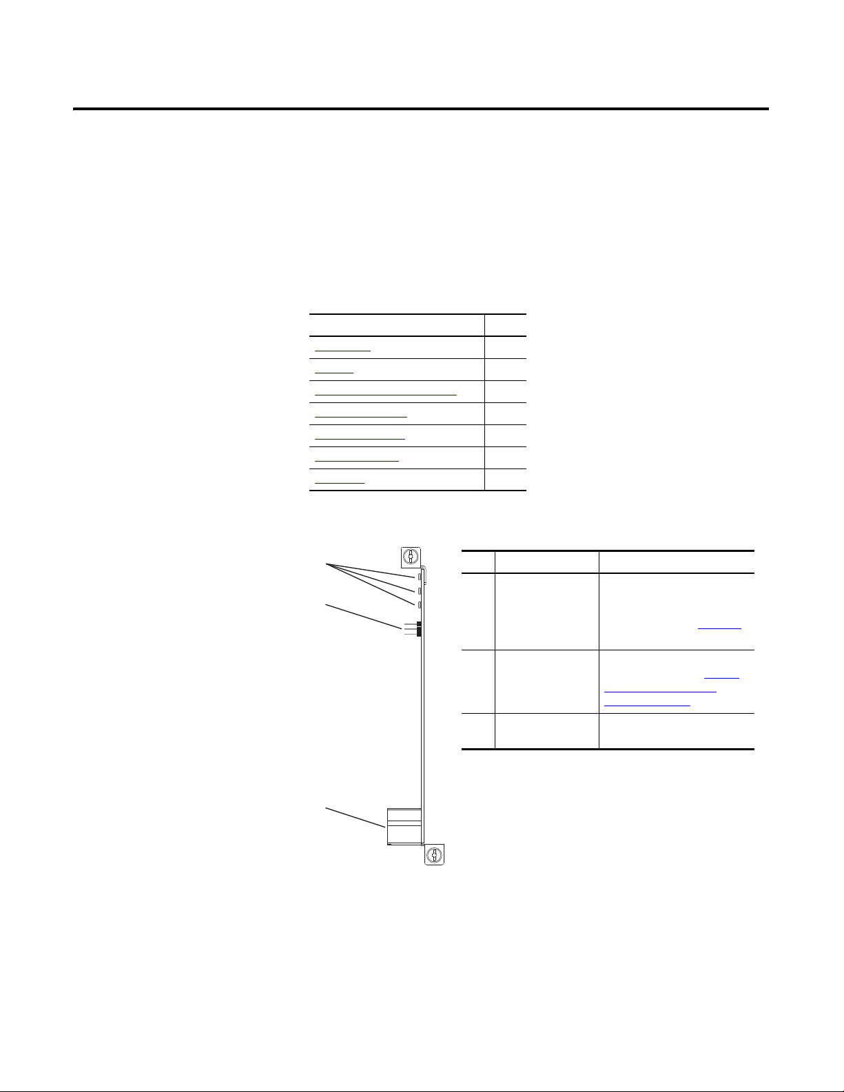
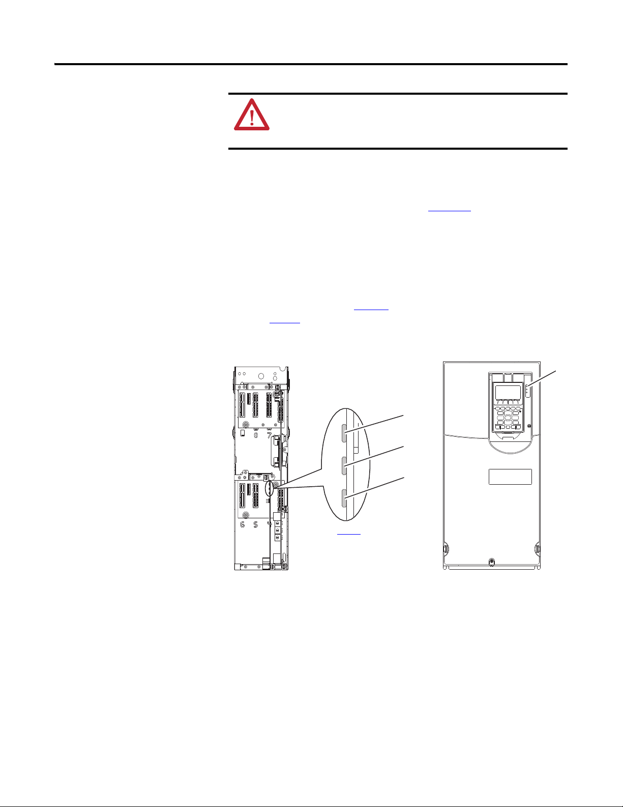
Item Part Description
➊ Status Indicators Three status indicators that
indicate the status of the option
module and network
communication. See Chapter 5
,
Troubleshooting.
➋ IP Address Selection
Jumper
Sets the source used for the
network address. See Setting
the IP Address Selection
Jumper on page 18.
➌ Ethernet Connector RJ45 connector for the Ethernet
network cable.
Getting Started
The 20-750-BNETIP option module is intended for installation into a
PowerFlex 750-Series drive and is used for network communication.
Topic Page
Components
Features 12
Understanding Parameter Types 12
Compatible Products
Required Equipment 13
Safety Precautions 15
Quick Start
11
13
16
1
Components
➊
➋
➌
Rockwell Automation Publication 750COM-UM005B-EN-P - June 2014 11
Page 12

Chapter 1 Getting Started
Features
The features of the option module include the following:
• Captive screws to secure and ground the option module to the drive.
• An IP Address Selection Jumper to set the source of the network address
for the option module before applying power to the drive. The network
address can come from the default network address of the option module,
a DHCP server, or the option module parameter values.
• Compatibility with the following configuration tools to configure the
option module and host drive:
– PowerFlex 20-HIM-A6 or 20-HIM-C6S HIM (Human Interface
Module) on the drive, if available
– Connected Components Workbench software, version 1.02 or later
– DriveExplorer software, version 6.01 or later
– DriveExecutive software, version 5.01or later
– Third party BACnet controlling and monitoring tools
• Status indicators that report the status of the option module and network
communication. They are visible when the drive cover is removed.
• Read/write access for parameters, where parameter values can be
configured and monitored over the network.
Understanding Parameter Types
• User-defined fault actions to determine how the option module and its
connected host drive respond to the following:
– I/O messaging communication disruptions (Comm Flt Action)
– Controllers in Idle mode (Idle Flt Action)
• Web pages, viewed by using a web browser, that show information about
the option module, its host drive, and DPI devices connected to the drive.
• Configurable e-mail messaging to desired addresses when selected drive
faults occur and/or are cleared, and/or when the option module takes a
communication or idle fault action.
The option module has two types of parameters:
• Device parameters are used to configure the option module to operate on
the network.
• Host parameters are used to configure the option module’s fault actions
with the drive.
12 Rockwell Automation Publication 750COM-UM005B-EN-P - June 2014
Page 13

Getting Started Chapter 1
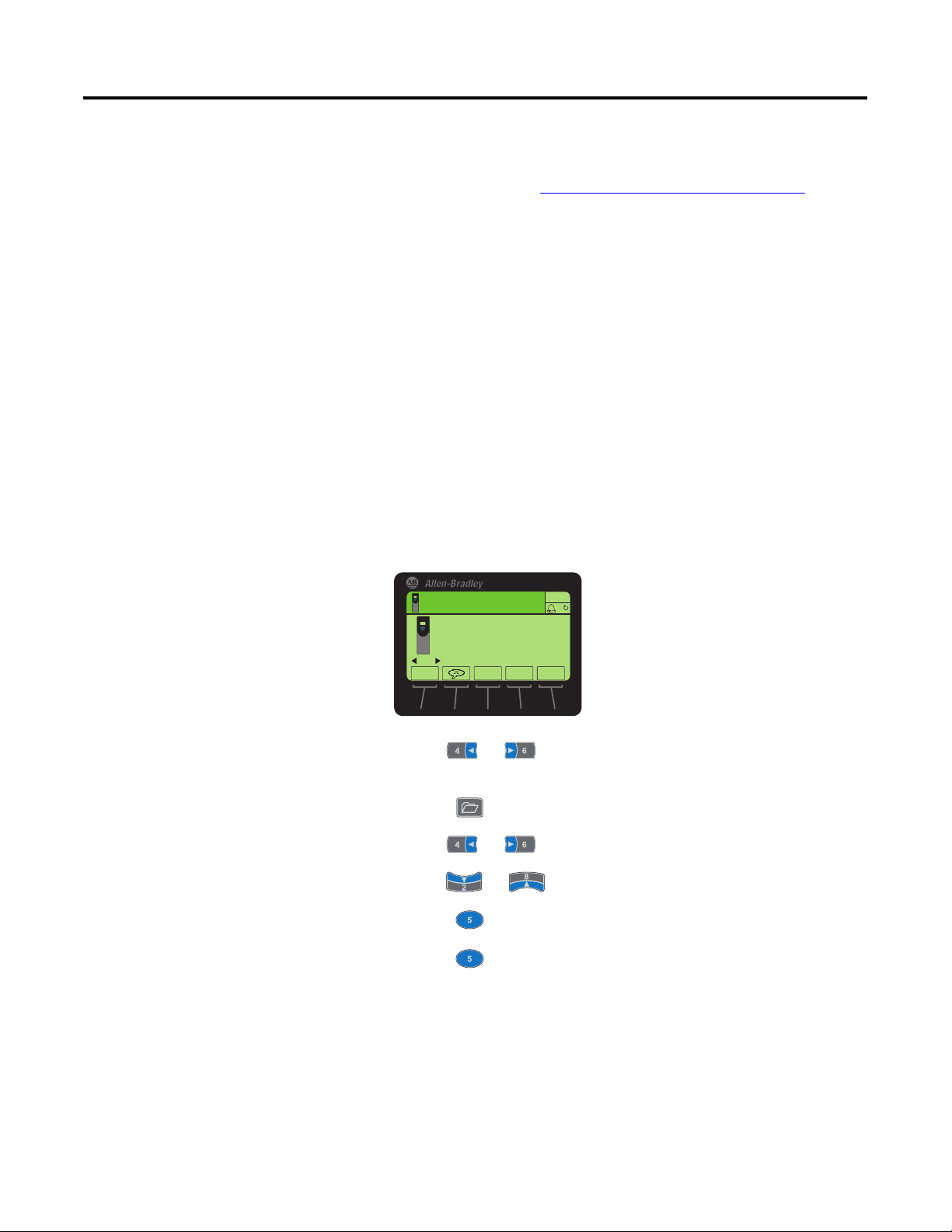
You ca n v ie w o pti on mo du le Device parameters and Host parameters with any of
the following drive configuration tools:
• PowerFlex 20-HIM-A6 or 20-HIM-C6S HIM—use the or
key to scroll to the drive port in which the module resides, press the
(Folders) key, and use the or key to scroll to the DEV PARAM
or HOST PARAM folder.
• Connected Components Workbench software—click the tab for the
option module at the bottom of the window, click the Parameters icon in
the tool bar, and click the Device or Host Parameters tab.
• DriveExplorer software—find the option module in the treeview and open
its Parameters folder.
• DriveExecutive software—find the option module in the treeview, expand
the module in the tree, and open its Parameters folder.
Compatible Products
Required Equipment
At the time of publication, the option module is compatible with the following
products:
• PowerFlex 753 drives (all firmware revisions)
• PowerFlex 755 drives (all firmware revisions)
Some of the equipment that is required for use with the option module is shipped
with the module, but some you must supply yourself.
Equipment Shipped with the Option Module
When you unpack the option module, verify that the package includes the
following:
❑ One 20-750-BNETIP BACnet/IP Option Module
❑ One Network Communication Option Module Installation Instructions,
publication 750COM-IN002
User-Supplied Equipment
To install and configure the option module, you must supply the following:
❑ A small screwdriver
Ethernet Cable
❑
Rockwell Automation Publication 750COM-UM005B-EN-P - June 2014 13
Page 14

Chapter 1 Getting Started
❑ Drive and option module configuration tool, such as the following:
– PowerFlex 20-HIM-A6 or 20-HIM-C6S HIM
– Connected Components Workbench software, version 1.02 or later
Connected Components Workbench is the recommended stand-alone
software tool for use with PowerFlex drives. You can obtain a free copy
by:
• Internet download at http://www.ab.com/support/abdrives/
webupdate/software.html
• Requesting a DVD at http://www.ab.com/onecontact/
controllers/micro800/
Your local distributor may also have copies of the DVD available.
Connected Components Workbench software cannot be used to
configure SCANport-based drives or Bulletin 160 drives.
– DriveExplorer software, version 6.01 or later
This software tool has been discontinued and is now available as
freeware at http://www.ab.com/support/abdrives/webupdate/
software.html. There are no plans to provide future updates to this tool
and the download is being provided ‘as-is’ for users that lost their
DriveExplorer CD, or need to configure legacy products not supported
by Connected Components Workbench software.
– DriveExecutive software, version 5.01 or later
A Lite version of DriveExecutive software ships with RSLogix 5000,
RSNetworx MD, FactoryTalk AssetCentre, and IntelliCENTER
software. All other versions are purchasable items:
• 9303-4DTE01ENE Drive Executive software
• 9303-4DTS01ENE DriveTools SP Suite (includes
DriveExecutive and DriveObserver software)
• 9303-4DTE2S01ENE DriveExecutive software upgrade to
DriveTools SP Suite (adds DriveObserver software)
DriveExecutive software updates (patches, and so forth) can be obtained
at http://www.ab.com/support/abdrives/webupdate/software.html
is highly recommended that you periodically check for and install the
latest update.
– Third party network configuration software such as ORCAview
❑ A computer connection to the BACnet network
. It
14 Rockwell Automation Publication 750COM-UM005B-EN-P - June 2014
Page 15

Getting Started Chapter 1
Safety Precautions
Please read the following safety precautions carefully.
ATTENTION: Risk of injury or death exists. The PowerFlex drive may
contain high voltages that can cause injury or death. Remove all power
from the PowerFlex drive, and then verify power has been discharged
before installing or removing an option module.
ATTENTION: Risk of injury or equipment damage exists. Only personnel
familiar with drive and power products and the associated machinery
should plan or implement the installation, startup, configuration, and
subsequent maintenance of the drive using the option module. Failure to
comply can result in injury and/or equipment damage.
ATTENTION: Risk of equipment damage exists. The option module
contains electrostatic discharge (ESD) sensitive parts that can be damaged
if you do not follow ESD control procedures. Static control precautions are
required when handling the option module. If you are unfamiliar with static
control procedures, see Guarding Against Electrostatic Damage,
publication 8000-4.5.2
ATTENTION: Risk of injury or equipment damage exists. If the option
module is transmitting control I/O to the drive, the drive can fault when you
reset the option module. Determine how your drive will respond before
resetting the module.
ATTENTION: Risk of injury or equipment damage exists. Host
Parameters 33 - [Comm Flt Action] and 34 - [Idle Flt Action] let you
determine the action of the option module and connected drive if I/O
communication is disrupted, the controller is idle, or messaging for drive
control is disrupted. By default, these parameters fault the drive. You can
configure these parameters so that the drive continues to run, however,
precautions must be taken to verify that the settings of these parameters
do not create a risk of injury or equipment damage. When commissioning
the drive, verify that your system responds correctly to various situations
(for example, a disconnected cable or a controller in idle state).
.
ATTENTION: Risk of injury or equipment damage exists. When a system is
configured for the first time, there can be unintended or incorrect machine
motion. Disconnect the motor from the machine or process during initial
system testing.
ATTENTION: Risk of injury or equipment damage exists. The examples in
this publication are intended solely for purposes of example. There are
many variables and requirements with any application. Rockwell
Automation does not assume responsibility or liability (to include
intellectual property liability) for actual use of the examples shown in this
publication.
Rockwell Automation Publication 750COM-UM005B-EN-P - June 2014 15
Page 16

Chapter 1 Getting Started
Quick Start
This section is provided to help experienced users quickly start using the option
module. If you are unsure how to complete a step, see the referenced chapter.
Step Action See
1 Review the safety precautions for the option module. Throughout this manual
2 Verify that the PowerFlex drive is properly installed. PowerFlex 750-Series AC Drive
Installation Instructions,
publication 750-IN001
3 Install the option module.
a. Verify that the PowerFlex drive is not powered.
b. Set the source for the option module network
address with the IP Address Selection Jumper
(Figure 1 on page 18
c. Insert the option module in drive Port 4, 5, or 6.
d. Use the captive screws to secure and ground the
option module to the drive.
e. Connect the option module to the network with an
Ethernet cable (and RJ45 connector).
4 Apply power to the option module.
a. Verify that the option module is installed correctly.
The option module receives power from the drive.
b. Apply power to the drive.
The status indicators should be green. If they flash
red, there is a problem. See Chapter 5
Troubleshooting.
c. Configure and verify key drive parameters.
5 Configure the option module for your application.
Set option module parameters for the following functions
as required by your application:
• Network Address
• Fault actions
6 Configure BACnet Objects.
Use a controller configuration tool, such as ORCAview,
that enables you to control the option module and
connected drive using BACnet Objects.
).
,
Network Communication Option
Card Installation Instructions,
publication 750COM-IN002
Chapter 2
Installing the Option Module
Chapter 2
Installing the Option Module
Chapter 3
Configuring the Option Module
Chapter 4
Using BACnet Services and
Objects
,
,
,
,
, and
16 Rockwell Automation Publication 750COM-UM005B-EN-P - June 2014
Page 17
Chapter
Installing the Option Module
This chapter provides instructions for installing the option module in a
PowerFlex 750-Series drive.
Topic Page
Preparing for an Installation
Setting the IP Address Selection Jumper 18
Connecting the Option Module to the Drive 19
Connecting the Option Module to the Network
Applying Power 20
Commissioning the Option Module 23
17
19
2
Preparing for an
Installation
Before installing the option module, verify that you have all required equipment.
See Required Equipment
ATTENTION: Risk of equipment damage exists. The option module
contains electrostatic discharge (ESD) sensitive parts that can be damaged
if you do not follow ESD control procedures. Static control precautions are
required when handling the option module. If you are unfamiliar with static
control procedures, see Guarding Against Electrostatic Damage,
publication 8000-4.5.2
on page 13.
.
Rockwell Automation Publication 750COM-UM005B-EN-P - June 2014 17
Page 18
Chapter 2 Installing the Option Module
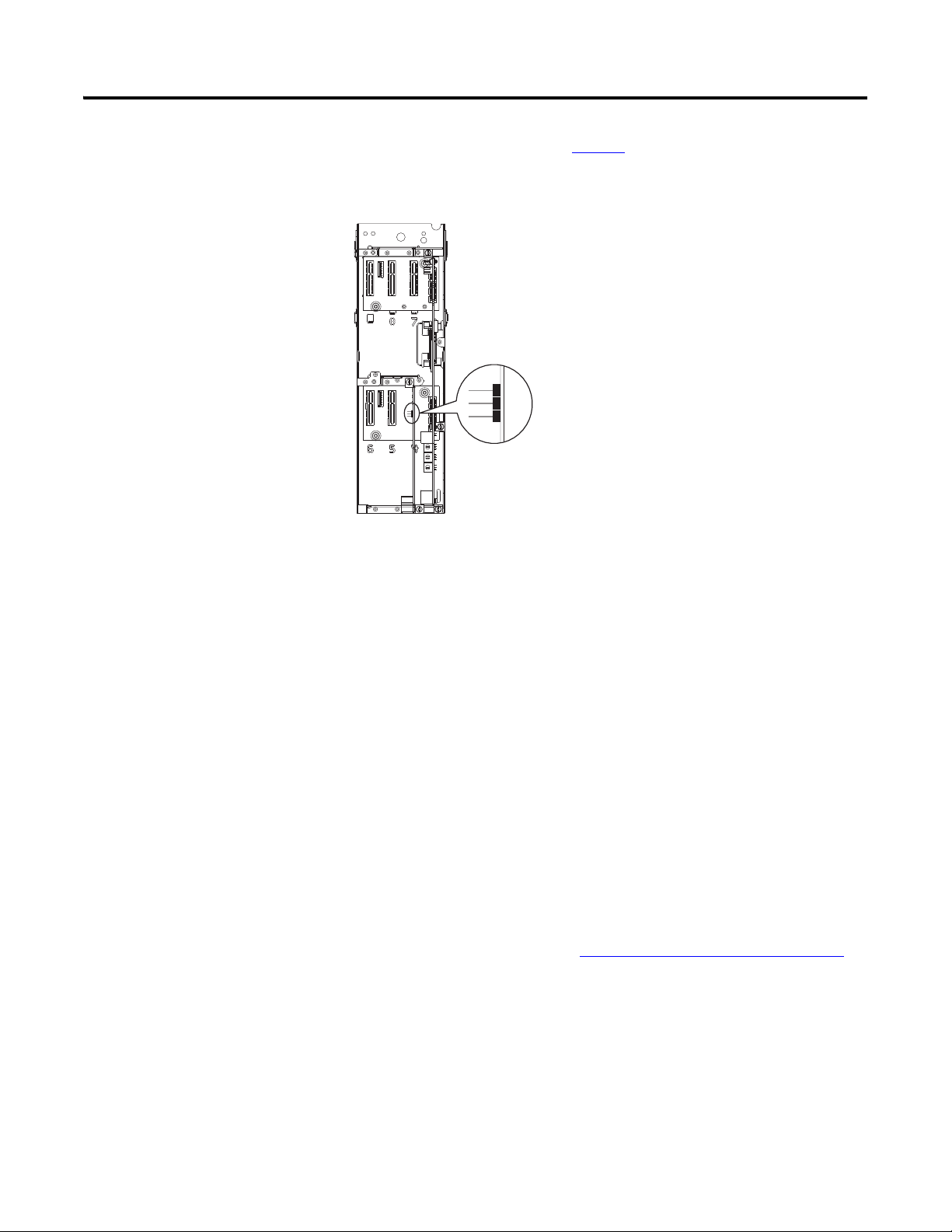
Pin 2 and 3 (DEFAULT setting)
Pin 1 and 2 (CONFIG setting) to
use option module parameters or
DHCP server for network address
Setting the IP Address Selection Jumper
The IP Address Selection Jumper (Figure 1) determines the source of the
network address for the option module.
Figure 1 - Setting the IP Address Selection Jumper
3
2
1
Using Default Network Address
When the jumper is on Pins 2 and 3 and Device Parameter 16 - [DHCP] is set to
‘0’ (Disabled), the following default network address is used:
• IP Address 192.168.0.1
• Subnet Mask 255.255.255.0
• Gateway 192.168.0.1
Using DHCP Server
When the jumper is on Pins 1 and 2 and Device Parameter 16 - [DHCP] is set to
‘1’ (Enabled), the network address is configured from a DHCP server. To set an
IP address using a DHCP server, do the following.
1. Set Device Parameter 16 - [DHCP] to ‘1’ (Enabled) to select the DHCP
server as the source for the IP address.
2. Reset the option module; see Resetting the Option Module
it can get the new IP address from the DHCP server.
Using Option Module Parameters
on page 33, so
18 Rockwell Automation Publication 750COM-UM005B-EN-P - June 2014
When the jumper is on Pins 1 and 2—or there is no jumper—and Device
Parameter 16 - [DHCP] is set to ‘0’ (Disabled), the network address is
configured with option module parameters.
Page 19

Installing the Option Module Chapter 2
IMPORTANT
IMPORTANT
Connecting the Option Module to the Drive
Connecting the Option Module to the Network
Remove power from the drive before installing the option module in the
drive control pod.
Install the option module in the PowerFlex 750-Series drive control pod in Port
4, 5, or 6. For more installation details, see the Network Communication Option
Module Installation Instructions, publication 750COM-IN002, provided with
the option module. See Figure 1
the drive.
After inserting the option module into drive Port 4, 5, or 6, make sure to
tighten the module screws to the pod mounting bracket to properly
ground the module to the drive. Torque both screws to 0.45…0.67 N•m
(4.0…6.0 lb•in).
ATTENTION: Risk of injury or death exists. The PowerFlex drive may
contain high voltages that can cause injury or death. Remove power from
the drive, and then verify power has been discharged before connecting the
option module to the network.
1. Remove power from the drive.
for an example of the option module installed in
2. Remove the drive cover and lift up the drive HIM bezel to its open
position to access the drive control pod.
3. Use static control precautions.
4. Connect one end of the Ethernet cable to the network.
5. Route the other end of the Ethernet cable through the bottom of the drive,
and insert its RJ45 male connector into the mating Ethernet connector of
the option module.
Rockwell Automation Publication 750COM-UM005B-EN-P - June 2014 19
Page 20
Chapter 2 Installing the Option Module
See Ta bl e 1 for
possible start-up
status indications.
Drive Control Pod
(drive shown with
cover removed)
Applying Power
ATTENTION: Risk of equipment damage, injury, or death exists.
Unpredictable operation can occur if you fail to verify that parameter
settings are compatible with your application. Verify that settings are
compatible with your application before applying power to the drive.
Apply power to the drive. The option module receives its power from the drive.
When you apply power to the option module for the first time, its topmost
‘PORT’ status indicator should be steady green or flashing green after an
initialization. If it is red, there is a problem. See Chapter 5
Start-Up Status Indications
After power has been applied, the drive STS (status) indicator can be viewed on
front of the drive and the option module status indicators can be viewed with the
drive cover open or removed (Figure 2
shown in Ta b l e 1
Figure 2 - Drive and Option Module Status Indicators
.
). Possible start-up status indications are
, Troubleshooting.
➊
➋
➌
➍
20 Rockwell Automation Publication 750COM-UM005B-EN-P - June 2014
Page 21

Installing the Option Module Chapter 2
Table 1 - Drive and Option Module Start-Up Status Indications
Item Name Color Status Description
Drive STS Indicator
STS
➊
(Status)
➋ PORT — Off The option module is not powered or connected properly to the drive.
➌ MOD — Off The option module is not powered or connected properly to the drive.
➍ NET A — Off The option module is not powered or connected properly to the network. The link is
Green Flashing Drive ready but not running, and no faults are present.
Steady Drive running, no faults are present.
Yellow Flashing When running, a type 2 (non-configurable alarm condition exists – drive continues to run.
When stopped, a start inhibit condition exists and the drive cannot be started (see drive
parameter 933 - [Start Inhibits]).
Steady A type 1 (user configurable) alarm condition exists, but the drive continues to run.
Red Flashing A major fault has occurred. Drive will stop. Drive cannot be started until fault condition is
cleared.
Steady A non-resettable fault has occurred.
Red/Yellow Flashing Alternately A minor fault has occurred. Use drive parameter 950 - [Minor Flt Config] to enable. If not
enabled, acts like a major fault. When running, the drive continues to run. System is
brought to a stop under system control. The fault must be cleared to continue.
Yellow/Green Flashing Alternately When running, a type 1 alarm exists.
Green/Red Flashing Alternately Drive firmware is updating.
Option Module Status Indicators
Red Flashing The option module is not receiving any communication from the drive.
Green Flashing Normal operation. The option module is establishing communication with drive. It will
Orange Steady The brand of the option module and drive do not match.
Red Flashing The option module has failed the firmware test or a firmware update is in progress.
Green Flashing Normal operation. The option module is operating but is not transferring I/O data to a
Red Flashing Any error in packet validation and/or execution is considered a network configuration
Green Steady Normal operation. The option module is properly connected and communicating on the
Steady The option module detected a duplicate or invalid port ID.
turn steady green or red.
Steady Normal operation. The option module is properly connected and communicating with the
drive.
Steady The option module has failed the hardware test.
controller.
Steady Normal operation. The option module is operating and transferring I/O data to a
Steady Any failure in self-test on the external Ethernet controller is considered a network
controller.
inactive.
error.
controller error.
network.
After verifying correct operation, swing down the drive HIM bezel to its closed
position and install the drive cover. For more details on status indicator
operation, see page 44
and page 45.
Rockwell Automation Publication 750COM-UM005B-EN-P - June 2014 21
Page 22
Chapter 2 Installing the Option Module
Configuring and Verifying Key Drive Parameters
The PowerFlex 750-Series drive can be separately configured for the control and
Reference functions in various combinations. For example, you could set the
drive to have its control come from a peripheral or terminal block with the
Reference coming from the network. Or you could configure the drive to have its
control come from the network with the Reference coming from another
peripheral or terminal block. Or you could set the drive to have both its control
and Reference come from the network.
The following steps in this section assume that the drive will receive the Logic
Command and Reference from the network.
1. Verify that drive Parameter 301 - [Access Level] is set to ‘1’ (Advanced) or
‘2’ (Expert) to access the required parameters in this procedure.
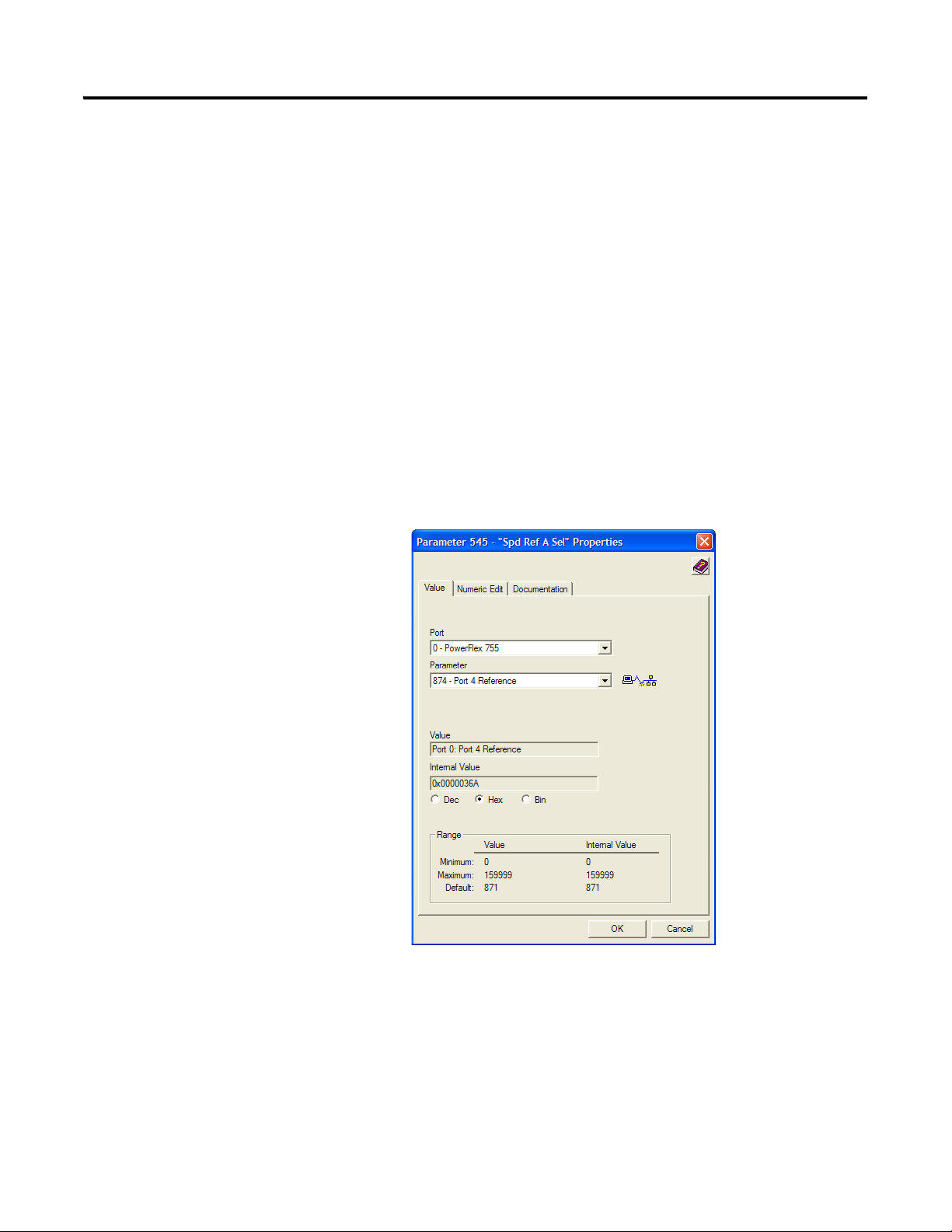
2. Use drive Parameter 545 - [Speed Ref A Sel] to set the drive speed
Reference.
a. Set the Port field to ‘0’ as shown below.
b. Set the Parameter field to point to the port (slot) in which the option
module is installed (for example, Port 4 Reference).
The number ‘874’ in the Parameter field of the example dialog box
above is the parameter in the drive that points to the port.
3. Verify that drive Parameter 930 - [Speed Ref Source] is reporting that the
source of the Reference to the drive (Port 0) is the port in which the option
module is installed (for example, Port 4 Reference).
22 Rockwell Automation Publication 750COM-UM005B-EN-P - June 2014
Page 23

Installing the Option Module Chapter 2
IMPORTANT
This ensures that any Reference commanded from the network can be
monitored by using drive Parameter 002 - [Commanded SpdRef ]. If a
problem occurs, this verification step provides the diagnostic capability to
determine whether the drive/option module or the network is the cause.
4. If hard-wired discrete digital inputs are not used to control the drive, verify
that all unused digital input drive parameters are set to ‘0’ (Not Used).
Commissioning the Option Module
To commission the option module, you must set a unique network node address.
See the Glossary
Selection Jumper on page 18 for details on selecting the source (default address,
from a DHCP server, or from option module parameters) for the network
address.
for details about IP addresses. Also, see Setting the IP Address
New settings for some option module parameters (for example Device
Parameters 04 - [IP Addr Cfg 1] through 07 - [IP Addr Cfg 4]) are
recognized only when power is applied to the option module or it is reset.
After you change parameter settings, cycle power or reset the option
module.
Rockwell Automation Publication 750COM-UM005B-EN-P - June 2014 23
Page 24

Chapter 2 Installing the Option Module
Notes:
24 Rockwell Automation Publication 750COM-UM005B-EN-P - June 2014
Page 25

IMPORTANT
Chapter
3
Configuring the Option Module
This chapter provides instructions and information for setting the parameters to
configure the option module.
Topic Page
Configuration Tools 25
Using the PowerFlex 20-HIM-A6 or 20-HIM-C6S HIM to Access Parameters 26
Setting the Option Module Address Using Parameters
Setting the Device Instance 28
Setting the Device Port 29
Setting a Fault Action
Setting the Comm Loss Time 31
Setting Web Page Access 32
Resetting the Option Module
Restoring Option Module Parameters to Factory Defaults 34
Viewing the Option Module Status Using Parameters 35
Updating the Option Module Firmware
26
29
33
35
Configuration Tools
For a list of parameters, see Appendix
definitions of terms in this chapter, see the Glossary
The option module stores parameters and other information in its own
nonvolatile storage (NVS) memory. You must, therefore, access the option
module to view and edit its parameters. The following tools can be used to access
the option module parameters.
Tool See
PowerFlex 20-HIM-A6 or
20-HIM-C6S HIM
Connected Components Workbench
software, version 1.02 or later
DriveExplorer software,
version 6.01 or later
DriveExecutive software,
version 5.01 or later
For the HIM screens shown throughout this chapter, the option module
was installed in drive Port 4. If your option module is installed in a
different drive port, that port would appear instead of Port 4.
B, Option Module Parameters. For
.
page 26
http://www.ab.com/support/abdrives/webupdate/
software.html, or online help (installed with the software)
http://www.ab.com/drives/driveexplorer
(installed with the software)
http://www.ab.com/drives/drivetools
(installed with the software)
, or online help
, or online help
Rockwell Automation Publication 750COM-UM005B-EN-P - June 2014 25
Page 26

Chapter 3 Configuring the Option Module
AUTO
ESC
ENTER
Stopped
0.00 Hz
F
▲
▼
Edit DHCP
Disabled 0
0<<1
Value Setting
0 Disabled
1 Enabled (Default)
Using the PowerFlex 20HIM-A6 or 20-HIM-C6S HIM
to Access Parameters
Setting the Option Module Address Using Parameters
If your drive has an enhanced PowerFlex 20-HIM-A6 or 20-HIM-C6S HIM, it
can be used to access parameters in the option module.
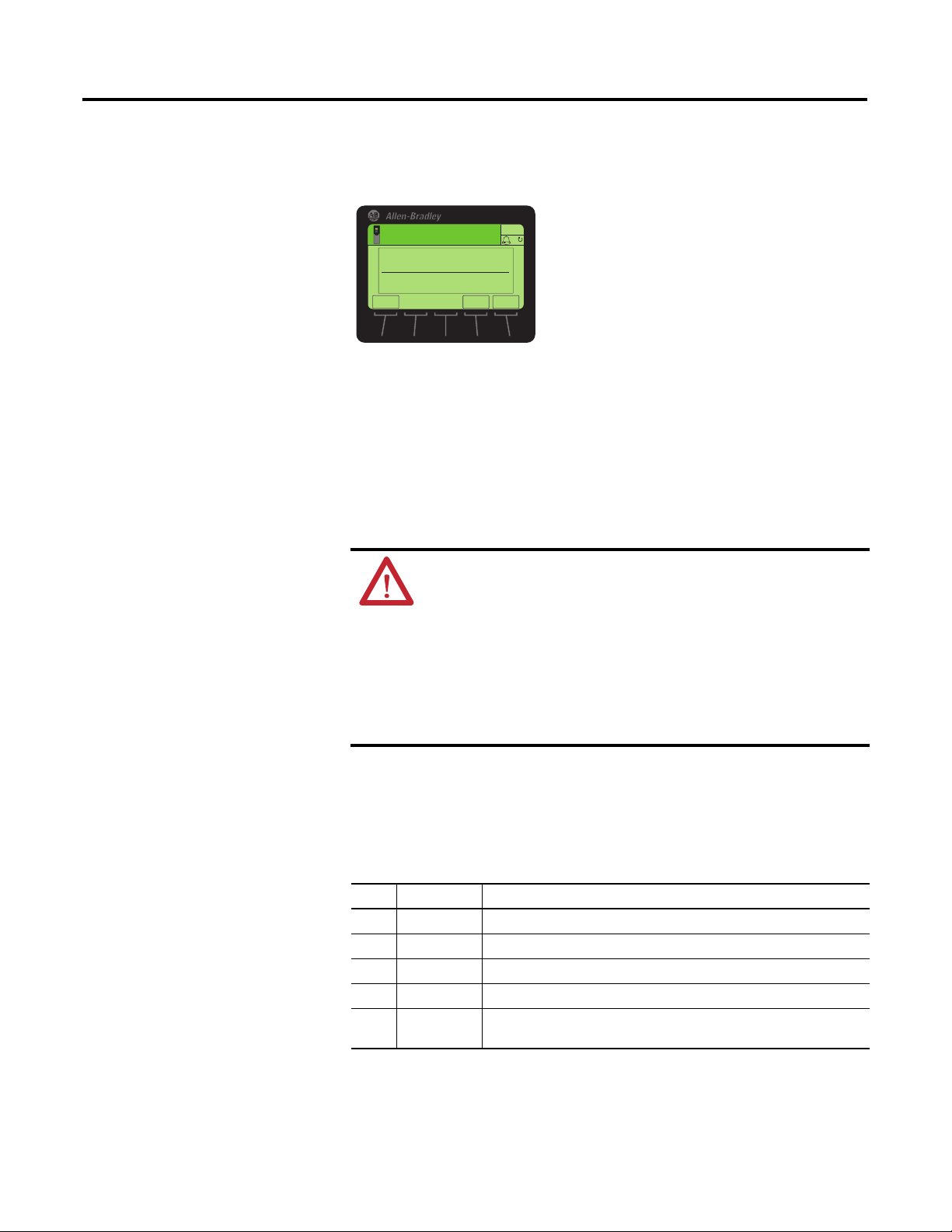
1. Display the Status screen, which is shown on HIM powerup.
2. Use the or key to scroll to the Port in which the option
module is installed.
3. Press the PAR# soft key to display the Jump to Param # entry pop-up box.
4. Use the numeric keys to enter the desired parameter number, or use the
or soft key to scroll to the desired parameter number.
For details on viewing and editing parameters, see the PowerFlex 20-HIM-A6/C6S HIM (Human Interface Module) User Manual, publication 20HIM-
UM001.
By default, the option module is provided with the IP address 192.168.0.1,
subnet mask 255.255.255.0, and gateway address 192.168.0.1. If you want to set
these attributes using the option module parameters, you must first disable
DHCP and then set the associated option module parameters as described in the
following subsections.
Disable the DHCP Feature
1. Set the value of Device Parameter 16 - [DHCP] to ‘0’ (Disabled).
2. Reset the option module; see Resetting the Option Module
After disabling the DHCP feature, you can then configure the IP address, subnet
mask, and gateway address using option module parameters.
Set the IP Address
1. Verif y th at Device Parameter 16 - [DHCP] is set to ‘0’ (Disabled).
26 Rockwell Automation Publication 750COM-UM005B-EN-P - June 2014
on page 33.
Page 27

Configuring the Option Module Chapter 3
ESC
ENTER
Stopped
0.00 Hz
AUTO
Edit IP Addr Cfg 1
0
0 << 255
F
Default = 0.0.0.0 255.255.255.255
[IP Addr Cfg 1]
[IP Addr Cfg 2]
[IP Addr Cfg 3]
[IP Addr Cfg 4]
Stopped
0.00 Hz F
Edit Subnet Cfg 1
0
0 << 255
ENTER
ESC
AUTO
Default = 0.0.0.0 255.255.255.255
[Subnet Cfg 1]
[Subnet Cfg 2]
[Subnet Cfg 3]
[Subnet Cfg 4]
ESC
ENTER
AUTO
F
Edit Gateway Cfg 1
0
0 << 255
Stopped
0.00 Hz
Default = 0.0.0.0 255.255.255.255
[Gateway Cfg 1]
[Gateway Cfg 2]
[Gateway Cfg 3]
[Gateway Cfg 4]
2. Set the value of Device Parameters 04 - [IP Addr Cfg 1] through 07 - [IP
Addr Cfg 4] to a unique IP address.
3. Reset the option module; see Resetting the Option Module
on page 33.
Set the Subnet Mask
1. Verif y th at Device Parameter 16 - [DHCP] is set to ‘0’ (Disabled).
2. Set the value of Device Parameters 08 - [Subnet Cfg 1] through 11 [Subnet Cfg 4] to the desired value for the subnet mask.
3. Reset the option module; see Resetting the Option Module
on page 33.
Set the Gateway Address
1. Verif y th at Device Parameter 16 - [DHCP] is set to ‘0’ (Disabled).
2. Set the value of Device Parameters 12 - [Gateway Cfg 1] through 15 -
Rockwell Automation Publication 750COM-UM005B-EN-P - June 2014 27
[Gateway Cfg 4] to the IP address of the gateway device.
3. Reset the option module; see Resetting the Option Module
on page 33.
Page 28
Chapter 3 Configuring the Option Module
Stopped
0.00 Hz
0 << 65535
ESC
ENTER
AUTO
F
Edit Device Instnc
100
Setting the Device Instance
A BACnet Device Instance number is used to identify a BACnet device over the
BACnet network. A Device Instance number must be unique across all subnets
and routed links.
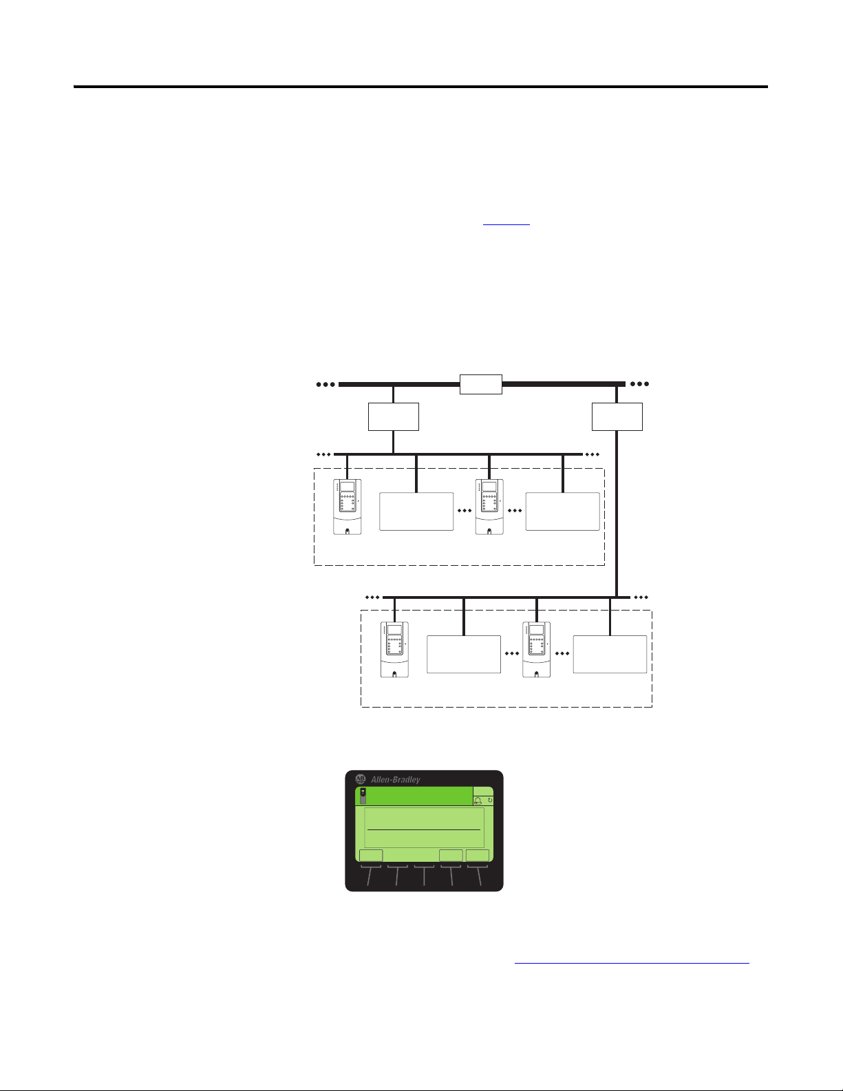
The Device Instance number could be configured depending upon the adopted
network strategy. For example Figure 3
shows a Building level network having
two individual floor networks through a router which allows devices on each
network to share the same IP address. Each device on the network in this example
has a unique Device Instance number consisting of 4 digits. The first digit
represents the Building or Floor number. The last 3 digits represent the fourth
octet of the device’s IP address.
Figure 3 - Building Automation Network Example
Building Level Network 1
IP Add. 192.168.120.121
Device Instance
1001
Building
Controller 1
Bldg 1/Flr 1
Other Brand
Building Automation
Product
IP Add. 192.168.120.122
Device Instance 1002
Router
Floor Level Network 1 (BACnet IP)
IP Add. 192.168.120.123
Device Instance 1050
Building Level Network 2
Other Brand
Building Automation
Product
IP Add. 192.168.120.124
Device Instance 1127
Building
Controller 2
Floor Level Network 1 (BACnet IP)
Bldg 2/Flr 2
Other Brand
Building Automation
Product
IP Add. 192.168.112.211
Device Instance 2001
IP Add. 192.168.112.212
Device Instance 2002
1. Set the value of Device Parameter 18 – [Device Instnc] to a unique
Device Instance number.
This Device Instance number should not be repeated within a BACnet
network. By default, the Device Instance number is set to 100.
2. Reset the option module; see Resetting the Option Module
28 Rockwell Automation Publication 750COM-UM005B-EN-P - June 2014
that the new Device Instance number takes effect.
IP Add. 192.168.112.213
Device Instance 2050
Other Brand
Building Automation
Product
IP Add. 192.168.112.214
Device Instance 2127
on page 33 so
Page 29
Configuring the Option Module Chapter 3
ESC
ENTER
Stopped
0.00 Hz
Edit Device Port
47808
0 << 60000
AUTO
F
Setting the Device Port
Setting a Fault Action
Setting the Device Port enables BACnet messaging to be sent and received by the
option module over the BACnet/IP network. Set Device Parameter 19 - [Device
Por t] to a value suitable for your application. By default, it is set to 47808.
By default, when communication is disrupted (for example, the network cable is
disconnected) or the controller is idle, the drive responds by faulting if it is using
I/O from the network. You can configure a different response to these faults:
• Disrupted I/O communication by using Host Parameter 33 - [Comm Flt
Action].
• An idle controller by using Host Parameter 34 - [Idle Flt Action].
ATTENTION: Risk of injury or equipment damage exists. Host
Parameters 33 - [Comm Flt Action] and 34 - [Idle Flt Action] let you
determine the action of the option module and connected drive if
communication is disrupted or the controller is idle. By default, these
parameters fault the drive. You can configure these parameters so that the
drive continues to run, however, precautions must be taken to verify that
the settings of these parameters do not create a risk of injury or equipment
damage. When commissioning the drive, verify that your system responds
correctly to various situations (for example, a disconnected network cable
or controller in idle state).
Changing the Fault Action
Set the values of Host Parameters 33 - [Comm Flt Action] and 34 - [Idle Flt
Action] to an action that meets your application requirements.
Value Action Description
0 Fault The drive is faulted and stopped. (Default).
1 Stop The drive is stopped, but not faulted.
2 Zero Data The drive is sent ‘0’ values for data. This does not command a stop.
3 Hold Last The drive continues in its present state.
4 Send Flt Cfg The drive is sent the data that you set in the fault configuration parameters
(Host Parameters 37 - [Flt Cfg Logic] and 38 - [Flt Cfg Ref]).
Rockwell Automation Publication 750COM-UM005B-EN-P - June 2014 29
Page 30

Chapter 3 Configuring the Option Module
ESC
ENTER
Stopped
0.00 Hz
AUTO
▲▼
Edit Idle Flt Action
Fault 0
0<<4
ESC
ENTER
Stopped
0.00 Hz
AUTO
▲▼
Edit Comm Flt Action
Fault 0
0<<4
Figure 4 - Edit Fault Action HIM Screens
Changes to these parameters take effect immediately. A reset is not required.
If communication is disrupted and then is re-established, the drive will
automatically receive commands over the network again.
Setting the Fault Configuration Parameters
When setting Host Parameters 33 - [Comm Flt Action] and 34 - [Idle Flt
Action] to ‘Send Flt Cfg’, the values in the following parameters are sent to the
drive after a communication fault and/or idle fault occurs. You must set these
parameters to values required by your application.
Option Module Host Parameter Description
Parameter 37 - [Flt Cfg Logic] A 32-bit value sent to the drive for Logic Command.
Parameter 38 - [Flt Cfg Ref] A 32-bit REAL (floating point) value sent to the drive for
Reference.
30 Rockwell Automation Publication 750COM-UM005B-EN-P - June 2014
Changes to these parameters take effect immediately. A reset is not required.
Page 31
Configuring the Option Module Chapter 3
ESC
ENTER
AUTO
F
Stopped
0.00 Hz
Edit Comm Loss Time
10
0<<180
Setting the Comm Loss Time
Set Device Parameter 17 - [Comm Loss Time] to a communication loss timeout
period suitable for your application.
By default, the timeout is set to 10 seconds. This value can be increased or
decreased. Alternatively, the value can be set to zero (0) to disable this timeout
feature so that the option module does not detect a communication loss.
ATTENTION: Risk of injury or equipment damage exists. Device
Parameter 17 - [Comm Loss Time] lets you determine how long it will
take the option module to detect a network communication loss. By
default, this parameter sets the timeout to ten (10) seconds. You can set it
so that the duration is shorter, longer, or disabled. When set to disabled,
this also disables Host Parameter 33 - [Comm Flt Action]. Therefore, a
communication fault action will be ignored. Take precautions to verify that
the setting does not create a risk of injury or equipment damage. When
commissioning the drive, verify that your system responds correctly to
various situations (for example, a disconnected cable).
Changes to this parameter take effect immediately. A reset is not required.
Rockwell Automation Publication 750COM-UM005B-EN-P - June 2014 31
Page 32

Chapter 3 Configuring the Option Module
Stopped
0.00 Hz
AUTO
F
Edit Web Enable
Disabled 0
0<<1
ESC
▲▼
ENTER
Value Description
0 Disabled (Default)
1 Enabled
Bit Description
0 E-mail Cfg (Default = 1 = Enabled)
1...7 Not Used
AUTO
F
Stopped
0.00 Hz
Edit Web Features
xxxx xxx1
E-mail Cfg
ES C ENTER
Setting Web Page Access
By using a web browser to access the IP address set for the option module, you
can view the option module web pages for information about the module, the
drive, and other DPI devices connected to the drive, such as HIMs or converters.
By default, the option module web pages are disabled. To enable the option
module web pages, do the following.
1. Set Device Parameter 26 - [Web Enable] to ‘1’ (Enabled).
2. Reset the option module; see Resetting the Option Module on page 33 so
that the change takes effect.
For more details on the option module web pages, see Chapter 6
Option Module Web Pages.
The option module can be configured to automatically send e-mail messages to
desired addresses when selected drive faults occur and/or are cleared, and/or
when the option module takes a communication or idle fault action.
, Viewing
32 Rockwell Automation Publication 750COM-UM005B-EN-P - June 2014
Bit 0 of Device Parameter 27 - [Web Features] is used to protect the configured
settings for e-mail messaging. By default, settings are not protected and the user
can make changes. To protect the configured settings, set the value of E-mail Cfg
Bit 0 to ‘0’ (Disabled). You can unprotect the configuration by changing Bit 0
back to ‘1’ (Enabled). E-mail messaging will always remain active regardless of
whether or not its settings are protected—unless e-mail messaging was never
configured. For more information about configuring option module e-mail
messaging or to stop e-mail messages, see Configure E-mail Notification Web
Page on page 56.
Bit 0 is the right-most bit. In the example above, it equals ‘1’ (Enabled).
Changes to this parameter take effect immediately. A reset is not required.
Page 33

Configuring the Option Module Chapter 3
IMPORTANT
TIP
Value Description
0 Ready (Default)
1 Reset Module
2 Set Defaults
AUTO
F
Stopped
0.00 Hz
Edit Reset Module
Ready 0
0 << 2
ES C ENTER
▲▼
Resetting the Option Module
Changes to the jumper setting and some option module parameters require you
to reset the option module before the new settings take effect. You can reset the
option module by power cycling the drive or by using Device Parameter 03 -
[Reset Module].
ATTENTION: Risk of injury or equipment damage exists. If the option
module is transmitting control I/O to the drive, the drive can fault when you
reset the option module. Determine how your drive will respond before
resetting the option module.
Set Device Parameter 03 - [Reset Module] to ‘1’ (Reset Module).
When you enter ‘1’ (Reset Module), the option module is immediately reset. An
alternate method to reset the module is by power cycling the drive. When you
enter ‘2’ (Set Defaults), the option module sets all of its Device and Host
parameters to their factory default values. (This is the same as pressing the ALL
soft key when using the MEMORY folder method described in Restoring Option
Module Parameters to Factory Defaults on page 34).
When performing a Set Defaults, the drive may detect a conflict and then
not allow this function to occur. If this happens, first resolve the conflict
and then repeat a Set Defaults action. Common reasons for a conflict
include a drive running or a controller (master) in Run mode.
After performing a Set Defaults, you must enter ‘1’ (Reset Module) or
power cycle the drive so that the new values take effect. Thereafter, this
parameter is restored to a value of ‘0’ (Ready).
Rockwell Automation Publication 750COM-UM005B-EN-P - June 2014 33
If your application allows, you can also reset the option module by
cycling power to the drive (resetting the drive) or by using the HIM’s
Reset Device function located in the drive’s DIAGNOSTIC folder.
Page 34
Chapter 3 Configuring the Option Module
00
ES C TEXT
Stopped
0.00 Hz
AUTO
Host Drive
240V 4.2A
Rev 3.002 Ser. A
F
REF PAR#
Restoring Option Module Parameters to Factory Defaults
As an alternate reset method, you can restore the option module parameters by
using a MEMORY folder menu item instead of using Device Parameter 03 -
[Reset Module] described in Resetting the Option Module
MEMORY folder method provides two ways to restore the option module
Device and Host parameters:
• ALL—restores ALL option module Device and Host parameters to their
factory default values.
• MOST—restores MOST option module Device and Host parameters—
except the following parameters which are used for network setup:
– Device Parameters 04 through 07 - [IP Addr Cfg 1-4]
– Device Parameters 08 through 11 - [Subnet Cfg 1-4]
– Device Parameters 12 through 15 - [Gateway Cfg 1-4]
– Device Parameter 16 - [DHCP]
Follow these steps to restore option module Device and Host parameters to their
factory default values.
1. Access the Status screen, which is displayed on HIM powerup.
on page 33. The
34 Rockwell Automation Publication 750COM-UM005B-EN-P - June 2014
2. Use the or key to scroll to the Port in which the option
module is installed.
3. Press the key to display its last-viewed folder.
4. Use the or key to scroll to the MEMORY folder.
5. Use the or key to select Set Defaults.
6. Press the (Enter) key to display the Set Defaults pop-up box.
7. Press the (Enter) key again to display the warning pop-up box to
reset Device and Host parameters to their factory default values.
8. Press the MOST soft key to restore MOST Device and Host parameters to
factory defaults, or press the ALL soft key to restore ALL parameters. Or
press the ESC soft key to cancel.
Page 35

Configuring the Option Module Chapter 3
IMPORTANT
When performing a Set Defaults, the drive may detect a conflict
and then not allow this function to occur. If this happens, first
resolve the conflict and then repeat this Set Defaults procedure.
Common reasons for a conflict include a drive running or a
controller (master) in Run mode.
9. Reset the option module using Device Parameter 03 - [Reset Module] or
by cycling power to the drive so that the restored parameters take effect.
Viewing the Option Module Status Using Parameters
Updating the Option Module Firmware
The following parameter provides information about the status of the option
module. You can view this parameter at any time.
Module Device Parameter Description
02 - [Net Addr Src] Displays the source from which the option module network address
is taken. It is either ’0’ (Parameters) or ‘1’ (Default) which uses the
following defaults:
• IP Address 192.168.0.1
• Subnet Mask 255.255.255.0
• Gateway Address 192.168.0.1
The option module firmware can be updated over the network or serially through
a direct connection from a computer to the drive using a 1203-USB or 1203-SSS
serial converter.
When updating firmware over the network, you can use the Allen-Bradley
ControlFLASH software tool, the built-in update capability of DriveExplorer
Lite or Full software, or the built-in update capability of DriveExecutive software.
When updating firmware through a direct serial connection from a computer to a
drive, you can use the same Allen-Bradley software tools described above, or you
can use HyperTerminal software set to the X-modem protocol.
To obtain a firmware update for this option module, go to http://www.ab.com/
support/abdrives/webupdate. This website contains all firmware update files and
associated Release Notes that describe the following items:
• Firmware update enhancements and anomalies
• How to determine the existing firmware revision
• How to update the firmware using ControlFLASH, DriveExplorer, or
DriveExecutive software.
Rockwell Automation Publication 750COM-UM005B-EN-P - June 2014 35
Page 36

Chapter 3 Configuring the Option Module
Notes:
36 Rockwell Automation Publication 750COM-UM005B-EN-P - June 2014
Page 37

Chapter
4
Using BACnet Services and Objects
This chapter provides information about controlling and monitoring a PowerFlex
750-Series drive using BACnet objects.
Topic Page
BACnet Services
Understanding BACnet Objects 38
Basic Drive Operation on the Network 39
Supported BACnet Objects
37
40
BACnet Services
BACnet services are used for exchanging data with a device over BACnet
protocol. A BACnet server offers a set of services, which can be viewed as a set of
messages (request or response). The option module supports these BACnet
services.
Object Access Services
Object Access Services is a set of services that are used to read and write the values
of parameters for the PowerFlex 750-Series drive and option module that are
represented by BACnet objects.
The option module supports the following Object Access Services:
• Read Property Service
• Write Property Service
• Read Property Multiple Service
• Write Property Multiple Service
Remote Device Management Services
Remote Device Management Services provide services that are used to access
details of the option module, other devices on the network, configuration of
communication settings, resetting the option module, and so forth.
These are the services supported by the option module:
• Who-Has and I-Have Services
• Who-Is and I-Am Services
Rockwell Automation Publication 750COM-UM005B-EN-P - June 2014 37
Page 38

Chapter 4 Using BACnet Services and Objects
The table below provides a brief description of these services.
Table 2 - BACnet Services Supported by the Option Module
Property Type Name Description
Object Access
Services
Remote Device
Management
Services
Read Property
Service
Write Property
Service
Read Property
Multiple Service
Write Property
Multiple Service
Who-Has and I-Have
Services
Who-Is and I-Am
Services
This service is used to read parameter values represented
by BACnet objects for the PowerFlex 750-Series drive or
option module.
This service is used to write values to parameters
represented by BACnet objects for the PowerFlex 750Series drive or option module.
This service is used to read multiple parameter values
represented by BACnet objects for the PowerFlex 750Series drive or option module.
This service is used to write values to multiple
parameters represented by BACnet objects for the
PowerFlex 750-Series drive or option module.
Who-Has service is a request to identify an object
specified by the object identifier or object name.
I-Have service is a response to respond to Who-Has
service requests.
Who-Is service is used to determine the device object
identifier, the network address, or both, for all BACnet
devices on the network.
I-Am service is used to respond to Who-Is service
requests. It is independent to Who-Is service and may be
issued at any time. It is also used to broadcast the
existence of the option module, or all BACnet devices on
the network.
Understanding BACnet Objects
BACnet devices are controlled and monitored by the use of several objects. The
BACnet controller performs read and write services to these objects, and the
option module translates the data between these objects and the PowerFlex 750Series drive.
When a read or write service occurs to a specific object, data in that object is
refreshed from or transferred to the drive.
These are the BACnet
• Analog Input (AI)
• Analog Output (AO)
• Analog Value (AV)
• Binary Input (BI)
• Binary Output (BO)
• Binary Value (BV)
object types supported by the option module:
38 Rockwell Automation Publication 750COM-UM005B-EN-P - June 2014
Page 39

Using BACnet Services and Objects Chapter 4
Basic Drive Operation on the Network
This section describes how to operate a drive on the network using a combination
of BACnet object types for basic control.
ATTENTION: Control information written to the option module by a
BACnet controller is volatile. That is, it will be erased by an option module
reset or power cycle. For example, if a BACnet controller writes to a Binary
Output (BO) object to energize an output relay on the drive and then that
drive is reset or power cycled, the drive returns the relay to its default
(de-energized) state. The option module does not attempt to restore the
relay to the energized state unless a BACnet controller writes to it again.
Basic Drive Control (Start/Stop)
Write a speed reference value (in %) to the Reference 1 Analog Value object
(AV0) Present Value property.
1. To start the drive, write a value of ‘1’ to the Run/Stop Binary Value object
(BV10) Present Value property.
2. To stop the drive, write a value of ‘0’ (zero) to the Run/Stop Binary Value
object (BV10) Present Value property.
Using an Alternate Speed Reference
Follow these steps to assign an alternate speed reference to the drive.
1. Write a speed reference value (in %) to the Reference 2 Analog Value
object (AV1) Present Value property.
2. Write a value of ‘1’ to the Ref2/Ref1 Binary Value object (BV12) Present
Val ue p rop er ty.
Changing Motor Rotation Direction
To command a reverse direction of motor rotation when the drive is running,
write a value of ‘1’ to the Rev/Fwd Binary Value object (BV11) Present Value
property. To command a forward direction when the drive is running, write a
value of ‘0’ (zero) to the Rev/Fwd Binary Value object (BV11) Present Value
property.
Clearing a Drive Fault
To clear a drive fault, write a value of ‘1’ to the Clear Faults Binary Value object
(BV13) Present Value property.
Rockwell Automation Publication 750COM-UM005B-EN-P - June 2014 39
Page 40

Chapter 4 Using BACnet Services and Objects
Supported BACnet Objects
Table 3 - BACnet Object Descriptions and Supported Drives
Object Name Use this Object to... Drive
AI0 Analog Input 1 (%) Read the value of Analog Input 1 (voltage or current) on the drive’s I/O
terminal block.
AO0 Analog Output 1 (%) Read/write the value of Analog Output on the drive’s I/O terminal block. 276 ✔ —
AV0 Speed Reference A Read/write the Speed Reference A. — ✔✔
AV1 Speed Reference B Read/write the Speed Reference B. — ✔✔
AV2 Output Frequency (Hz) Read the drive’s output frequency. 1 ✔✔
AV3 Output Current (Amps) Read the drive’s output current. 7 ✔✔
AV4 Output Voltage (VAC) Read the drive’s output voltage. 8 ✔✔
AV5 Output Power (kW) Read the drive’s output power. 9 ✔✔
AV6 Output Energy (kWh) Read/write the drive’s accumulated output energy.
AV7 Output Energy 2 (MWh) Read/write the drive’s accumulated Output energy in terms of MWh.
AV8 DC Bus Voltage (VDC) Read the drive’s DC bus voltage. 11 ✔✔
AV9 Drive Temp (°C) Read the drive’s temperature. 944 ✔✔
AV10 Reserved — — — —
AV11 Run Time (Hours) Read/write the drive’s accumulated run time.
AV12 Fault 1 Read the code for the drive’s most recent fault. DPI Fault
AV13 Fault 2 Read the code for the drive’s second most recent fault. DPI Fault
AV14 Fault 3 Read the code for the drive’s third most recent fault. DPI Fault
AV15 Accel Time 1 (Sec) Read/write the drive’s Accel Time 1 setting. 535 ✔✔
AV16 Accel Time 2 (Sec) Read/write the drive’s Accel Time 2 setting. 536 ✔✔
AV17 Decel Time 1 (Sec) Read/write the drive’s Decel Time 1 setting. 537 ✔✔
AV18 Decel Time 2 (Sec) Read/write the drive’s Decel Time 2 setting. 538 ✔✔
AV19 Reference 1 (%) Read/write the Reference 1. 545 ✔✔
AV20 Reference 2 (%) Read/write the Reference 2. 550 ✔✔
Important: When writing, this object accepts only a value of ‘0’ (zero).
Important: When writing, this object accepts only a value of ‘0’ (zero).
Important: When writing, this object accepts only a value of ‘0’ (zero).
The type of drive used on the network determines the specific BACnet objects
that are supported. See Ta b l e 3
drives supporting those objects.
Analog Input (AI) Objects
Analog Output (AO) Objects
Analog Value (AV) Objects
for descriptions of the BACnet objects and the
Parameter
Number
260 ✔ —
14 ✔✔
13 ✔✔
15 ✔✔
Object
Object
Object
PowerFlex 750Series Drive
753 755
✔✔
✔✔
✔✔
✔✔
✔✔
40 Rockwell Automation Publication 750COM-UM005B-EN-P - June 2014
Page 41

Table 3 - BACnet Object Descriptions and Supported Drives (Continued)
Using BACnet Services and Objects Chapter 4
Object Name Use this Object to... Drive
Parameter
Number
AV21 Mailbox1 Param Read/write any drive parameter.
AV22 Mailbox1 Value — ✔✔
AV23 Mailbox2 Param — ✔✔
AV24 Mailbox2 Value — ✔✔
AV25 Mailbox3 Param — ✔✔
AV26 Mailbox3 Value — ✔✔
AV27 Mailbox4 Param — ✔✔
AV28 Mailbox4 Value — ✔✔
AV29 Mailbox5 Param — ✔✔
AV30 Mailbox5 Value — ✔✔
AV31 Mailbox6 Param — ✔✔
AV32 Mailbox6 Value — ✔✔
AV33 Mailbox7 Param — ✔✔
AV34 Mailbox7 Value — ✔✔
AV35 Mailbox8 Param — ✔✔
AV36 Mailbox8 Value — ✔✔
BI0 Digital Input 0 Read the state of Digital Input 0 on the drive’s OBJECTS terminal block. 220 (Bit 0) ✔✔
B11 Digital Input 1 Read the state of Digital Input 1 on the drive’s OBJECTS terminal block. 220 (Bit 1) ✔ —
BI2 Digital Input 2 Read the state of Digital Input 2 on the drive’s OBJECTS terminal block. 220 (Bit 2) ✔ —
BO0 Output Relay 0 Read/write the state of Output Relay 0 227 ✔ —
BV0 RUN Ready Read the drive’s RUN Ready status. Logic Status
BV1 Active Read the drive’s Active status, which is enabled if the drive is running. Logic Status
To read a drive parameter, write the number for the desired parameter to
the Mailbox Param object, and then read the Mailbox value object.
To write a drive parameter, write the number for the desired parameter to
the Mailbox Param object, and then write the desired value to the
Mailbox Value object.
Binary Input (BI) Objects
Binary Output (BO) Objects
Binary Value (BV) Objects
BV2 Forward/Reverse Read the drive’s Actual Direction status, which is active if the drive is
BV3 Fault Read the drive’s Fault status, which is active if the drive is faulted. Logic Status,
BV4 Alarm Read the drive’s Alarm status, which is active if the drive has an alarm. Logic Status
BV5 At Setpt Spd Read the drive’s Setpd Spd status, which is enabled if the drive is running
BV6 Manual Active Read the drive’s Manual Mode setting.
running.
at the specified speed reference.
0 = Manual Mode Not Active; 1 = Manual Mode Active
— ✔✔
Word, Bit 0
Word, Bit 1
Logic Status
Word, Bit 3
Word, Bit 7
Word, Bit 6
Logic Status
Word, Bit 8
Logic Status
Word, Bit 9
PowerFlex 750Series Drive
753 755
✔✔
✔✔
✔✔
✔✔
✔✔
✔✔
✔✔
Rockwell Automation Publication 750COM-UM005B-EN-P - June 2014 41
Page 42

Chapter 4 Using BACnet Services and Objects
Table 3 - BACnet Object Descriptions and Supported Drives (Continued)
Object Name Use this Object to... Drive
Parameter
Number
BV10 Run/Stop Read/write the drive’s Run/Stop command. Turn on this object to start the
drive/turn off bit to stop the drive.
BV11 Rev/Fwd Read/write the drive’s Rev/Fwd command. Turn on this object to
command the reverse direction when the drive is running. Turn off this
object to command Forward.
BV12 Ref2/Ref1 Read/write the drive’s Ref2/Ref1 command. Turn on this object to select
the Reference 2 instance of the AV object as the drive’s speed reference.
Turn off this object to select Reference 1.
BV13 Clear Faults Read/write the drive’s Clear Faults command. Turn on this object to clear
the drive fault. Turning off this object does nothing.
BV14 Auto/Manual Read/write the drive’s Auto/Manual setting.
0 = Not manual; 1 = Manual
Logic
Command
Word, Bit 18
Logic
Command
Word, Bits 4
and 5
Logic
Command
Word, Bits
12, 13, and
14
Logic
Command
Word, Bit 3
Logic
Command
Word, Bit 6
PowerFlex 750Series Drive
753 755
✔✔
✔✔
✔✔
✔✔
✔✔
42 Rockwell Automation Publication 750COM-UM005B-EN-P - June 2014
Page 43

Chapter
5
Troubleshooting
This chapter provides information for diagnosing and troubleshooting potential
problems with the option module and network.
Topic Page
Understanding the Status Indicators
PORT Status Indicator 44
MOD Status Indicator 44
NET A Status Indicator
Viewing Option Module Diagnostic Items 45
Viewing and Clearing Events 47
43
45
Understanding the Status
Indicators
The option module has three status indicators. They can be viewed with the drive
cover removed.
➊
➋
➌
Item Status Indicator Description Page
➊ PORT DPI Connection Status 44
➋ MOD Option Module Status 44
➌ NET A BACnet Status 45
Rockwell Automation Publication 750COM-UM005B-EN-P - June 2014 43
Page 44

Chapter 5 Troubleshooting
PORT Status Indicator
Status Cause Corrective Action
Off The option module is not powered or is not
Flashing Red The option module is not receiving any
Steady Red The option module detected a duplicate or invalid
Flashing Green The option module is establishing communication
Steady Green The option module is properly connected and
Steady Orange The brand of the option module and drive do not
This red/green bicolor LED indicates the status of the option module’s
connection to the drive as shown in the table below.
properly connected to the drive.
communication from the drive.
port ID.
with the drive.
communicating with the drive.
match.
• Securely connect and ground the option module to the
drive by fully inserting it into the drive port and
tightening its two captive screws to the recommended
torque.
• Apply power to the drive.
• Verify that the option module is properly inserted in the
drive port.
• Cycle power to the drive.
Important: Cycle power to the drive after securely
connecting and grounding the option module to the drive by
fully inserting it into the drive port and tightening its two
captive screws to the recommended torque.
No action required. This status indicator will turn steady
green or red.
No action required.
Connect the option module to a compatible product of the
same brand (an Allen-Bradley PowerFlex 750-Series drive).
MOD Status Indicator
Status Cause Corrective Action
Off The option module is not powered or is not
Flashing Red The option module has failed the firmware test. • Cycle power to the drive. Parameter settings may have
Steady Red The option module has failed the hardware test. • Cycle power to the drive.
Flashing Green The option module is operating normally, but is
Steady Green The option module is operating and is
This red/green bicolor LED indicates the status of the option module as shown
in the table below.
properly connected to the drive.
not transferring BACnet data.
transferring BACnet data to the controller.
• Securely connect and ground the option module to the
drive by fully inserting it into the drive port and
tightening its two captive screws to the recommended
torque.
• Apply power to the drive and network.
been changed.
• Clear faults in the option module.
• If cycling power does not correct the problem, the option
module parameter settings may have been corrupted.
Reset defaults and reconfigure the option module.
• If resetting defaults does not correct the problem, update
the option module with the latest firmware revision.
• Replace the option module.
• Place the Client in RUN mode.
• Configure the option module for the program in the
controller.
• Program the controller to recognize and transmit BACnet
data to the option module.
• Normal behavior if no communication is taking place.
No action required.
44 Rockwell Automation Publication 750COM-UM005B-EN-P - June 2014
Page 45

Troubleshooting Chapter 5
NET A Status Indicator
Status Cause Corrective Actions
Off The option module is not powered or is not
Flashing Red Any error in packet validation and/or execution is
Steady Red Any failure in self-test on the external Ethernet
Steady Green The option module is properly connected and
Viewing Option Module Diagnostic Items
This red/green bicolor LED indicates the status of the network connection to the
option module as shown in the table below.
properly connected to the network. The link is
inactive.
considered a network configuration error.
controller is considered a network controller
error.
communicating on the network.
If you encounter unexpected communications problems, the option module’s
diagnostic items may help you or Rockwell Automation personnel troubleshoot
the problem. Option module diagnostic items can be viewed with any of these
drive configuration tools:
• PowerFlex 20-HIM-A6 or 20-HIM-C6S HIM
• Connected Components Workbench software, version 1.02 or later
• DriveExplorer software, version 6.01 or later
• DriveExecutive software, version 5.01 or later
• Securely connect the option module to the drive and
connect it to the network with a CAT5 cable.
• Correctly connect the network cable to the option
module’s RJ45 Ethernet connector.
• Apply power to the drive.
Re-configure the option module.
• Cycle power to the drive.
• Re-configure the BACnet Client.
No action required.
For details on viewing diagnostic items using the HIM, see the PowerFlex 20HIM-A6/-C6S HIM (Human Interface Module) User Manual, publication
20HIM-UM001
Table 4 - Option Module Diagnostic Items
No. Name Description
1 Common Logic Cmd The present value of the Common Logic Command being transmitted to the drive by this option module.
2 Prod Logic Cmd The present value of the Product Logic Command being transmitted to the drive by this option module.
3 Reference The present value of the Reference being transmitted to the drive by this option module.
4 Common Logic Sts The present value of the Common Logic Status being received from the drive by this option module.
5 Prod Logic Sts The present value of the Product Logic Status being received from the drive by this option module.
6 Feedback The present value of the Feedback being received from the drive by this option module.
7 DPI Rx Errs The present value of the DPI CAN Receive error counter register.
8 DPI Rx Errs Max The maximum value of the DPI CAN Receive error counter register.
9 DPI Tx Errs The present value of the DPI CAN Transmit error counter register.
10 DPI Tx Errs Max The maximum value of the DPI CAN Transmit error counter register.
11 Boot Flash Count The number of times the boot firmware in this option module has been updated.
12 App Flash Count The number of times the application firmware in this option module has been updated.
.
Rockwell Automation Publication 750COM-UM005B-EN-P - June 2014 45
Page 46

Chapter 5 Troubleshooting
255:255:255:255:255:255
[HW Addr 1]
[HW Addr 2]
[HW Addr 3]
[HW Addr 4]
HW Addr 5]
[HW Addr 6]
255.255.255.255
[IP Addr Act 1]
[IP Addr Act 2]
[IP Addr Act 3]
[IP Addr Act 4]
255.255.255.255
[Subnet Act 1]
[Subnet Act 2]
[Subnet Act 3]
[Subnet Act 4]
255.255.255.255
[Gateway Act 1]
[Gateway Act 2]
[Gateway Act 3]
[Gateway Act 4]
Table 4 - Option Module Diagnostic Items (Continued)
No. Name Description
13
14
15
16
17
18
19 Net Rx Pckt The number of packets received from the network.
20 Net Rx Err The present value of error packets received from the network.
21 Net Rx Terr The total number of error packets received from the network.
22 Net Tx Pckt The number of packets transmitted by the option module.
23 Net Tx Err The present value of error packets transmitted by the option module.
24 Net Tx Terr A count of the total number of transmitted error packets by the option module.
25 BACnet Rx Err The present value of BACnet error packets received from the network.
26
27
28
29
HW Addr 1
HW Addr 2
HW Addr 3
HW Addr 4
HW Addr 5
HW Addr 6
IP Addr Act 1
IP Addr Act 2
IP Addr Act 3
IP Addr Act 4
Decimal value of each byte in the option module’s Ethernet hardware address.
Value of each byte in the option module’s present IP address. A value of ‘0’ appears if the option module does not
currently have an IP address.
30
31
32
33
34
35
36
37
Subnet Act 1
Subnet Act 2
Subnet Act 3
Subnet Act 4
Gateway Act 1
Gateway Act 2
Gateway Act 3
Gateway Act 4
Value of each byte in the option module’s present subnet mask. A value of ‘0’ appears if the option module does not
currently have a subnet mask.
Value of each byte in the option module’s present gateway address. A value of ‘0’ appears if the option module does not
currently have a gateway address.
46 Rockwell Automation Publication 750COM-UM005B-EN-P - June 2014
Page 47

Troubleshooting Chapter 5
Viewing and Clearing Events
The option module has an event queue to record significant events that occur in
the operation of the module. When such an event occurs, an entry consisting of
the event’s numeric code and a timestamp is put into the event queue. You can
view the event queue with any of these drive configuration tools:
• PowerFlex 20-HIM-A6 or 20-HIM-C6S HIM
• Connected Components Workbench software, version 1.02 or later
• DriveExplorer software, version 6.01 or later
• DriveExecutive software, version 5.01 or later)
For details on viewing and clearing events using the HIM, see the PowerFlex 20HIM-A6/-C6S HIM (Human Interface Module) User Manual, publication
20HIM-UM001
The event queue can contain up to 32 entries, which are stored in an EEPROM
—making the event queue nonvolatile. Eventually the event queue will
chip
become full, since its contents are retained through option module power cycles
and resets. At that point, a new entry replaces the oldest entry. Only an event
queue clear operation or the corruption of the EEPROM group containing the
event queue will clear the event queue contents. In the latter case, the option
module will not generate a fault to indicate that the event queue was corrupted.
Resetting the option module to defaults has no effect on the event queue, other
than to log a Code 58 ‘Module Defaulted’ event.
.
Many events in the event queue occur under normal operation. If you encounter
unexpected communications problems, the events may help you or Allen-Bradley
personnel troubleshoot the problem. The following events may appear in the
event queue.
Table 5 - Option Module Events
Code Event Text Description
Option Module Events
1 No Event Text displayed in an empty event queue entry.
2 Device Power Up Power was applied to the option module.
3 Device Reset The option module was reset.
4 EEPROM CRC Error The EEPROM checksum/CRC is incorrect, which limits option module functionality. Default parameter values must be
5 App Updated The option module application firmware was updated.
6 Boot Updated The option module boot firmware was updated.
7 Watchdog Timeout The software watchdog detected a failure and reset the option module.
8 DPI Bus Off A bus-off condition was detected on DPI. This event may be caused by noise.
9 DPI Ping Timeout A ping message was not received on DPI within the specified time.
10 DPI Port Invalid The Option Module was not connected to a valid port on a DPI product.
11 DPI Port Changed The DPI port changed after startup.
loaded to clear this condition.
DPI Events
Rockwell Automation Publication 750COM-UM005B-EN-P - June 2014 47
Page 48

Chapter 5 Troubleshooting
Table 5 - Option Module Events (Continued)
Code Event Text Description
12 DPI Host Reset The drive sent a reset event message.
13 DPI Baud 125kbps The option module detected that the drive was communicating at 125 Kbps.
14 DPI Baud 500kbps The option module detected that the drive was communicating at 500 Kbps.
15 DPI Host Invalid The option module was connected to an incompatible product.
16 DPI Dup Port Another peripheral with the same port number is already in use.
17 DPI Type 0 Logon The option module has logged in for Type 0 control.
18 DPI Type 0 Time The option module has not received a Type 0 status message within the specified time.
19 DPI DL Logon The option module has logged into a Datalink.
20 DPI DL Error The drive rejected an attempt to log in to a Datalink because the Datalink is not supported or is used by another
peripheral.
21 DPI DL Time The option module has not received a Datalink message within the specified time.
22 DPI Ctrl Disable The option module has sent a ‘Soft Control Disable’ command to the drive.
23 DPI Ctrl Enable The option module has sent a ‘Soft Control Enable’ command to the drive.
24 DPI Msg Timeout A Client-Server message sent by the option module was not completed within 1 second.
25 DPI Manual Reset The option module was reset by changing its Reset Module parameter.
SI Events
26 SI Online The option module has logged into the Serial Interface Communications.
27 SI Logon Error The option module failed to log into the Serial Interface.
28 SI Comm Fault The Serial Interface Communications has faulted.
29 Net Link Up A network link was available for the option module.
30 Net Link Down The network link was removed from the option module.
31 Net Dup Address The option module uses the same address as another device on the network.
32 Net Comm Fault The option module detected a communications fault on the network.
33 Net Sent Reset The option module received a reset from the network.
34 Net IO Close An I/O connection from the network to the option module was closed.
35 Net Idle Fault The option module received ‘idle’ packets from the network.
36 Net IO Open An I/O connection from the network to the option module has been opened.
37 Net IO Timeout An I/O connection from the network to the option module has timed out.
38 Net IO Size Err The option module received an incorrectly sized I/O packet.
39 PCCC IO Close The device sending PCCC Control messages to the option module has set the PCCC Control Timeout to zero.
40 PCCC IO Open The option module has begun receiving PCCC control messages (the PCCC Control Timeout was previously set to a
41 PCCC IO Timeout The option module has not received a PCCC Control message for longer than the PCCC Control Timeout.
42 Msg Ctrl Open The timeout attribute in either the CIP Register or Assembly object was written with a non-zero value, allowing
43 Msg Ctrl Close The timeout attribute in either the CIP Register or Assembly object was written with a zero value, disallowing control
44 Msg Ctrl Timeout The timeout attribute in either the CIP Register or Assembly object elapsed between accesses of those objects.
45 Peer IO Open The option module received the first Peer I/O message.
Network Events
non-zero value).
control messages to be sent to the option module.
messages to be sent to the option module.
48 Rockwell Automation Publication 750COM-UM005B-EN-P - June 2014
Page 49

Troubleshooting Chapter 5
Table 5 - Option Module Events (Continued)
Code Event Text Description
46 Peer IO Timeout The option module has not received a Peer I/O message for longer than the Peer I/O Timeout.
47-54 Reserved —
55 DHCP Response The option module received a response to its DHCP request.
56 Email Failed The option module encountered an error attempting to send a requested e-mail message.
57 Option Card Flt Internal option module faults.
58 Module Defaulted The option module has been set to defaults.
59 No MAC Addr A MAC address has not been assigned, or the MAC address is invalid.
Rockwell Automation Publication 750COM-UM005B-EN-P - June 2014 49
Page 50

Chapter 5 Troubleshooting
Notes:
50 Rockwell Automation Publication 750COM-UM005B-EN-P - June 2014
Page 51

Chapter
6
Viewing Option Module Web Pages
This chapter provides instructions on how to monitor the PowerFlex 750-Series
drive and its BACnet/IP option module by using the module’s web interface.
Topic Page
Enabling the Option Module Web Pages 51
Viewing the Web Pages
Process Display Pop-up Dialog Box 54
BACnet/IP Configuration Web Page 55
Configure E-mail Notification Web Page
Device Information Pages 59
Future enhancements may result in option module web pages that look different
than the examples shown in this chapter.
51
56
Enabling the Option Module Web Pages
Viewing the Web Pages
After the option module is configured and operating, you can view its web pages.
They present information about the module, the drive to which it is connected,
and the other DPI devices connected to the drive such as a HIM.
By default the option module web pages are disabled. To enable the option
module web pages, set Device Parameter 26 - [Web Enable] to ‘1’ (Enabled) and
then reset the option module for the change to take effect.
The option module can be configured to automatically send e-mail messages to
desired addresses when selected drive faults occur and/or are cleared, and/or
when the option module takes a communication or idle fault action.
Bit 0 of Device Parameter 27 - [Web Features] can be used to protect the
configured settings. For more details, see Configure E-mail Notification Web
Page on page 56.
1. On a computer with access to the BACnet network on which the drive/
option module is installed, launch a web browser such as Microsoft
Internet Explorer, version 5.0 or later.
™
The computer can access the option module web pages if it is connected to:
• The same network as the drive/option module.
• A network with access to the drive/option module’s network via a
gateway device (for example, a router).
Rockwell Automation Publication 750COM-UM005B-EN-P - June 2014 51
Page 52

Chapter 6 Viewing Option Module Web Pages
IMPORTANT
➊
➋
➌
2. In the Address box, type the IP address of the option module.
3. Press ENTER.
The option module web Home Page (Figure 5
Using the browser’s View menu, choose Refresh to always redisplay the option module Home Page while viewing any of the
module’s other web pages.
Figure 5 - Option Module Web Home Page Example
) appears.
Title Bar on Option Module Web Pages
The title bar appears on the option module Home Page and all of the module’s
other web pages. The title bar consists of three elements as shown in Figure 5
Title Bar Element Description
➊ Allen-Bradley logo This logo is a hyperlink. Click it to view the ab.com web Home Page.
➋ Option Module Title Shows the option module type or user-configured title.
➌ Rockwell Automation logo This logo is a hyperlink. Click it to view the Rockwell Automation
web Home Page.
52 Rockwell Automation Publication 750COM-UM005B-EN-P - June 2014
.
Page 53

Viewing Option Module Web Pages Chapter 6
Navigation Pane on Option Module Web Pages
The navigation pane appears on the left side of the option module Home Page
and all of the module’s other web pages. The navigation pane consists of links and
link folders which can be expanded or minimized. The following table shows all
navigation pane links and link folders.
Navigation Pane Link/ Folder Description
Home link Click this link to view the module’s Home Page (Figure 5).
Process display link Click this link to view the host drive’s Process Display pop-up dialog box
(Figure 6
).
BACnet/IP configuration link Click this link to view the module’s BACnet/IP Configuration web page
Configure e-mail notification
link
Browse devices folder Click this folder to expand and view the Port folders for all present
Port x folders Click a respective Port folder to expand and view its device’s various
Online user manuals link Click this link to view Rockwell Automation’s web page with
Software tools Web site link Click this link to view Allen-Bradley’s web page with information about
Launch my DriveExplorer
software link
Launch my DriveExecutive
software link
E-mail technical support link Click this link to view a new e-mail message dialog box to send a
showing information about the BACnet/IP configuration, such as the
module’s IP address, subnet mask, gateway address, and so forth.
Figure 7
shows an example BACnet/IP Configuration web page.
Click this link to view the module’s Configure E-mail Notification web
page (Figure 8
messages. An example e-mail message is shown in Figure 11
devices, including the drive, option module, and other devices connected
to the drive such as a HIM.
links which take you to related information pages. For Port 0 (PowerFlex
750-Series drive) example information pages, see Figure 12
and Figure 14
documentation for drives and other devices.
software tools such as DriveExplorer and DriveExecutive.
Click this link to launch the DriveExplorer software already installed on
your computer.
Click this link to launch the DriveExecutive software already installed on
your computer.
message to the Allen-Bradley Technical Support Team.
) to configure the option module to send automatic e-mail
.
, Figure 13,
.
Information on Option Module Home Page
The option module Home Page displays the following information for the host
PowerFlex 750-Series drive and its BACnet/IP option module.
Device Information
20-750-BNETIP Option Module • Revision
• IP Address
• Ethernet Address (MAC)
Host PowerFlex 750-Series drive • Revision
• Status
• Commanded Direction
• Serial Number
• Status
• I/O Connection Status
• Rotation Direction
• Process Status
Rockwell Automation Publication 750COM-UM005B-EN-P - June 2014 53
Page 54

Chapter 6 Viewing Option Module Web Pages
Process Display Pop-up Dialog Box
The Process Display pop-up dialog box dynamically shows the host drive’s
information. To view this dialog box, click the ‘Process display’ link in the
navigation pane.
Figure 6 - Example of Process Display Pop-up Dialog Box
Information Description
Product Text Description of host drive.
Status Status of host drive.
Commanded Direction Commanded direction of host drive.
Rotation Direction Rotation direction of host drive.
Process Status
1st Line Dynamic value of the host drive feedback parameter. This parameter
is not selectable.
Lines 2 through 7 Dynamic value of each default-displayed host drive parameter. The
displayed drive parameters for lines 2 through 7 are selectable by
using a HIM, or another drive configuration tool such as Connected
Components Workbench, DriveExecutive, or DriveExplorer software.
54 Rockwell Automation Publication 750COM-UM005B-EN-P - June 2014
Page 55

Viewing Option Module Web Pages Chapter 6
BACnet/IP Configuration Web Page
The BACnet/IP Configuration web page provides information about the option
module’s Ethernet settings and network activities. To view this web page, click the
‘BACnet/IP configuration’ link (highlighted in
Figure 7 - Example of BACnet/IP Configuration Web Page
Information Description
IP address IP address of the option module.
Subnet mask Subnet mask for the option module’s network.
Gateway address Address for the gateway device on the option module’s network.
DHCP Shows status for DHCP, which may be used to configure the option
module’s network information.
Ethernet address (MAC) Hardware address for the option module.
BBMD address IP address of the BBMD device.
BBMD Port Port address of the BBMD device.
Device Instance Instance number of the option module on the BACnet network.
Foreign Device Registration Status of foreign device, which may be used to configure the Foreign
device on the BACnet network.
Figure 7) in the navigation pane.
Rockwell Automation Publication 750COM-UM005B-EN-P - June 2014 55
Page 56

Chapter 6 Viewing Option Module Web Pages
Configure E-mail Notification Web Page
The Configure E-mail Notification web page contains selections and data fields
for configuring the option module to automatically send email messages to
desired addresses when selected types of events occur. To view this web page, click
the ‘Configure e-mail’ link (highlighted in Figure 8
Figure 8 - Example of Configure E-mail Notification Web Page
) in the navigation pane.
By default, settings are not protected. After configuration, settings can be
protected by using Device Parameter 27 - [Web Features] to set E-mail Cfg Bit 0
value to ‘0’ (Disabled). To change a protected configuration, it must first be
unprotected by setting the E-mail Cfg Bit 0 value back to ‘1’ (Enabled).
To configure e-mail notification, perform the following steps.
1. Click the desired ‘Send an e-mail message when’ check boxes you want to
occur that will send e-mail notification.
If you want email notification only when selected faults/alarms occur:
a. Click the respective fault and/or alarm radio buttons.
b. Click the ‘selected faults’ link and/or ‘selected alarms’ link.
c. Click the desired fault/alarm check boxes.
d. Click Save Changes.
e. Click the ‘Back to E-mail Configuration Page’ link.
56 Rockwell Automation Publication 750COM-UM005B-EN-P - June 2014
Page 57

Viewing Option Module Web Pages Chapter 6
TIP
Figure 9 - Example of Selected Faults for E-mail Notification Configuration
Page
2. Type the following information in their respective boxes.
Information Field Description
‘IP address of…’ Type in the address of the mail server that will be used to deliver the
‘E-mail addresses to
notify…’
‘Subject of e-mail
message…’
email messages. (When the IP address is unknown, read the TIP
shown below this table to determine the mail server address.)
Type in addresses to where you want email messages to be sent.
Multiple addresses can be used, but they must be separated by
commas (comma delimited).
Type in the desired subject text for the email message.
If the IP address of the email server is unknown, you can contact
your IT department or use the following DOS command
instructions to find its IP address.
a. From the Start menu on the Windows task bar, choose Run to
display the Run dialog box.
b. In the Run dialog box Open field, type ‘cmd’.
c. Click OK to display the DOS dialog box.
d. On the c:\ > command line, type ‘nslookup [name of e-mail
server].’
The entry ‘c:\ > nslookup smtp.company.com’ is an example.
e. Press Enter to display the e-mail server IP address (Figure 10
f. Type the second (bottom) IP address shown in the DOS dialog
box (for this example, 131.200.165.58) into the E-mail
Notification web page (Figure 8
).
).
Rockwell Automation Publication 750COM-UM005B-EN-P - June 2014 57
Page 58

Chapter 6 Viewing Option Module Web Pages
IMPORTANT
TIP
Figure 10 - DOS Dialog Box Example Showing Email Server IP Address
3. Click Save Changes.
After configuring E-mail Notification, we recommend protecting
the settings. Otherwise the configuration can be changed anytime
the web page is accessed with a browser. To protect the settings,
use Device Parameter 27 - [Web Features] to set E-mail Cfg Bit
0 value to ‘0’ (Disabled).
The figure below shows an example email message automatically sent by the
option module in response to selected events.
Figure 11 - Example of Email Message Sent by the Option Module
To stop email messages, uncheck all of the ‘Send an e-mail message
when…’ boxes.
Disabling the option module web pages by setting Device Parameter 26
- [Web Enable] to ‘0’ (Disabled) will not stop the option module from
sending email messages.
58 Rockwell Automation Publication 750COM-UM005B-EN-P - June 2014
Page 59
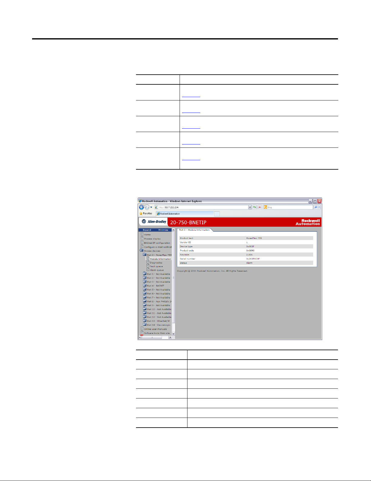
Viewing Option Module Web Pages Chapter 6
Device Information Pages
Device information pages are viewed by clicking on the respective links in the
navigation pane.
Web Page Description
Module Information Shows module information for the respective Port device. For example,
Figure 12
shows module information for the Port 0 device (host drive).
Diagnostic Items Shows diagnostic item information for the respective Port device. For example,
Fault Queue Shows fault queue information for the respective Port device. For example,
Alarm Queue Shows alarm queue information for the respective Port device. For example,
Event Queue
(1) Information shown only when supported by the device.
Figure 12 - Example of Port 0 (PowerFlex 750-Series Drive) Module Information Page
(1)
shows diagnostic items for the Port 0 device (host drive).
Figure 13
Figure 14
shows the fault queue for the Port 0 device (host drive).
Figure 15
shows the alarm queue for the Port 0 device (host drive).
Shows event queue information for the respective Port device. For example,
shows the event queue for the Port 4 device (BACnet/IP option
Figure 16
module).
Information Description
Product text Text identifying the device
Vendor ID 1 = Allen-Bradley
Device type 0x008F (143 decimal)
Product code Code for the product name and its rating
Revision Firmware revision used by the device
Serial number Serial number of the device
Status Operating status of the device (for example, Alarm)
Rockwell Automation Publication 750COM-UM005B-EN-P - June 2014 59
Page 60

Chapter 6 Viewing Option Module Web Pages
Figure 13 - Example of Port 0 (PowerFlex 750-Series Drive) Diagnostic Items Page
Figure 14 - Example of Port 0 (PowerFlex 750-Series Drive) Fault Queue Page
60 Rockwell Automation Publication 750COM-UM005B-EN-P - June 2014
Page 61

Viewing Option Module Web Pages Chapter 6
Figure 15 - Example of Port 0 (PowerFlex 750-Series Drive) Alarm Queue Page
Figure 16 shows an example event queue page for the Port 4 device (BNET/IP
option module).
Figure 16 - Example of Port 4 (20-750-BNETIP Option Module) Event Queue Page
Rockwell Automation Publication 750COM-UM005B-EN-P - June 2014 61
Page 62

Chapter 6 Viewing Option Module Web Pages
Notes:
62 Rockwell Automation Publication 750COM-UM005B-EN-P - June 2014
Page 63

Appendix
Specifications
This appendix presents the specifications for the option module.
Topic Page
Communication 63
Electrical
Mechanical 63
Environmental 64
Regulatory Compliance
63
64
A
Communication
Electrical
Mechanical
Network
Protocol
Data Rates
Media
Drive
Protocol
Data Rates
Consumption
Drive
Network
Dimensions
Height
Length
Width
Weight 60 g (2 oz.)
BACnet/IP
10/100 Mbps
Ethernet cable with RJ45 connector
DPI
500 Kbps
250 mA at 14 VDC supplied by the host drive
None
16 mm (0.63 inches)
130 mm (5.12 inches)
83 mm (3.27 inches)
Rockwell Automation Publication 750COM-UM005B-EN-P - June 2014 63
Page 64

Appendix A Specifications
Environmental
Regulatory Compliance
Temperature
Operating
Storage
Relative Humidity
Operating
Non-operating
Shock (Operating) 15 g peak acceleration
Vibration
Operating
Non-Operating
Atmosphere Important: The option module must not be installed in an area
Certification Specification
BTL SSPC135
UL UL508C
cUL CAN/ CSA C22.2 No.14-M91
CE EN 61800-3
C-Tick EN 61800-3
-5…65 °C (30…149 °F)
-40…85 °C (-40…185 °F)
5…80% non-condensing
5…95% non-condensing
2 g at 55...512 Hz
5 g at 5 Hz...2 kHz
where the ambient atmosphere contains volatile or corrosive
gas, vapors or dust. If the option module is not going to be
installed for a period of time, it must be stored in an area where
it will not be exposed to a corrosive atmosphere.
NOTE: This is a product of category C2 according to IEC 61800-3. In a
domestic environment this product may cause radio interference in which case
supplementary mitigation measures may be required.
64 Rockwell Automation Publication 750COM-UM005B-EN-P - June 2014
Page 65

Appendix
Option Module Parameters
This appendix provides information about the option module parameters.
Topic Page
Parameter Types 65
About Parameter Numbers
How Parameters Are Organized
Device
Parameters 66
Host
Parameters 69
66
66
B
Parameter Types
The option module has two types of parameters:
• Device parameters are used to configure the option module to operate on the
network.
• Host parameters are used to configure the option module’s various fault
actions with the drive.
Yo u c an vie w o pt io n mo du le Device and Host parameters with any of the
following drive configuration tools:
• PowerFlex 20-HIM-A6 or 20-HIM-C6S HIM—use the or
key to scroll to the drive port in which the module resides, press the
(Folders) key, and use the or key to scroll to the DEV
PARA M or HO ST PAR AM f ol der.
• Connected Components Workbench software—click the tab for the
option module at the bottom of the window, click the Parameters icon in
the tool bar, and click the Device or Host Parameters tab.
• DriveExplorer software—find the option module in the treeview and open
its Parameters folder.
• DriveExecutive software—find the option module in the treeview, expand
the module in the tree, and open its Parameters folder.
Rockwell Automation Publication 750COM-UM005B-EN-P - June 2014 65
Page 66

Appendix B Option Module Parameters
IMPORTANT
ATTENTION: Risk of injury or equipment damage exists. If the option
module is transmitting I/O that controls the drive, the drive can fault
when you reset the option module. Determine how your drive will
respond before resetting the option module.
About Parameter Numbers
How Parameters Are Organized
Device Parameters
Each parameter set is independently and consecutively numbered.
Configuration Tool Numbering Scheme
• HIM
• Connected Components Workbench software
• DriveExplorer software
• DriveExecutive software
The Device Parameters and Host Parameters are separately displayed in a
Numbered List view order.
The 20-750-BNETIP Option Module does not support all Host parameters
that appear in the configuration tool. A list of supported Host parameters
is provided later in this appendix.
Parameter
No. Name and Description Details
01 [Port Number]
Displays the drive port into which the option
module is installed. Typically, this is Port 4, 5, or 6.
02 [Net Addr Src]
Displays the source from which the option
module’s node address is taken.
03 [Reset Module]
No action if set to ‘0’ (Ready). Resets the option
module if set to ‘1’ (Reset Module). Restores the
option module to its factory default settings if set
to ‘2’ (Set Defaults). This parameter is a command.
It will be reset to ‘0’ (Ready) after the command
has been performed.
When performing a Set Defaults, the drive may
detect a conflict. If this occurs, the drive will not
allow a Set Defaults action. You must resolve the
conflict before attempting a Set Defaults action for
the option module.
Device parameters begin with parameter 01
(Device Parameter 01 - [Port Number]).
Host parameters begin with parameter 33
(Host Parameter 33 - [Comm Flt Action]).
Minimum: 4
Maximum: 6
Type: Read Only
Values: 0 = Parameters
1 = Default
Type: Read Only
Default: 0 = Ready
: 0 = Ready
Values
1 = Reset Module
2 = Set Default
Type: Read/Write
Reset Required: No
66 Rockwell Automation Publication 750COM-UM005B-EN-P - June 2014
Page 67

255.255.255.255
[IP Addr Cfg 1]
[IP Addr Cfg 2]
[IP Addr Cfg 3]
[IP Addr Cfg 4]
255.255.255.255
[Subnet Cfg 1]
[Subnet Cfg 2]
[Subnet Cfg 3]
[Subnet Cfg 4]
255.255.255.255
[Gateway Cfg 1]
[Gateway Cfg 2]
[Gateway Cfg 3]
[Gateway Cfg 4]
Option Module Parameters Appendix B
Parameter
No. Name and Description Details
04
[IP Addr Cfg 1]
05
[IP Addr Cfg 2]
06
[IP Addr Cfg 3]
07
[IP Addr Cfg 4]
Sets the IP address bytes for the option module’s
network address when the IP Address Selection
Jumper (Figure 1 on page 18
2—or the jumper is missing.
Important: To set the IP address using these
parameters, Device Parameter 16 - [DHCP] must
be set to ‘0’ (Disabled).
08
[Subnet Cfg 1]
09
[Subnet Cfg 2]
10
[Subnet Cfg 3]
11
[Subnet Cfg 4]
Sets the subnet mask bytes for the option module’s
network address.
) is set on Pins 1 and
Default: 192
Default: 168
Default: 0
Default: 1
Minimum: 0
Maximum: 255
Type: Read/Write
Reset Required: Yes
Default: 255
Default: 255
Default: 255
Default: 0
Minimum: 0
Maximum: 255
Type: Read/Write
Reset Required: Yes
Important: To set the subnet mask using these
parameters, Device Parameter 16 - [DHCP] must
be set to ‘0’ (Disabled).
12
[Gateway Cfg 1]
13
[Gateway Cfg 2]
14
[Gateway Cfg 3]
15
[Gateway Cfg 4]
Sets the gateway address bytes for the option
module’s network address.
Important: To set the gateway address using
these parameters, Device Parameter 16 - [DHCP]
must be set to ‘0’ (Disabled).
Default: 192
Default: 168
Default: 0
Default: 1
Minimum: 0
Maximum: 255
Type: Read/Write
Reset Required: Yes
Rockwell Automation Publication 750COM-UM005B-EN-P - June 2014 67
Page 68

Appendix B Option Module Parameters
ATTENTION: Risk of injury or equipment damage exists. Device
Parameter 17 - [Comm Loss Time] lets you determine how long it will
take the option module to detect a network communication loss. By
default, this parameter sets the timeout to ten (10) seconds. You can set
it so that the duration is shorter, longer, or disabled. When set to
disabled, this also disables Host Parameter 33 - [Comm Flt Action].
Therefore, a communication fault action will be ignored. Take
precautions to verify that the setting does not create a risk of injury or
equipment damage. When commissioning the drive, verify that your
system responds correctly to various situations (for example, a
disconnected cable).
255.255.255.255
[BBMD Cfg 1]
[BBMD Cfg 2]
[BBMD Cfg 3]
[BBMD Cfg 4]
Parameter
No. Name and Description Details
16 [DHCP]
Enables/disables the Dynamic Host Configuration
Protocol server for setting the IP address of the
option module.
17 [Comm Loss Time]
Sets the communication loss timeout period in
seconds. The value zero (0) disables this function.
Default: 0 = Disabled
Values: 0 = Disabled
Type: Read/Write
Reset Required: Yes
Default: 10 seconds
Minimum: 0 seconds
Maximum: 180 seconds
Type: Read/Write
Reset Required: No
1 = Enabled
18 [Device Instnc]
Sets the Device Instance number used by the
option module on the BACnet network.
19 [Device Port]
Sets the network node Device Port for the option
module to enable BACnet messaging to be sent
and received over the BACnet/IP network.
20 [BBMD Port Number]
Sets the Port number for BACnet Broadcast
Management Device connection.
21
[BBMD Cfg 1]
22
[BBMD Cfg 2]
23
[BBMD Cfg 3]
24
[BBMD Cfg 4]
Sets the bytes in the IP Address of the BACnet
Broadcast Management Device.
Default: 100
Minimum: 0
Maximum: 65535
Type: Read/Write
Reset Required: Yes
Default: 47808
Minimum: 0
Maximum: 60000
Type: Read/Write
Reset Required: Yes
Default: 47808
Minimum: 0
Maximum: 60000
Type: Read/Write
Reset Required: Yes
Default: 0
Default: 0
Default: 0
Default: 0
Minimum: 0
Maximum: 255
Type: Read/Write
Reset Required: Yes
68 Rockwell Automation Publication 750COM-UM005B-EN-P - June 2014
Page 69

Option Module Parameters Appendix B
Bit
Definition
Not Used
Not Used
Not Used
Not Used
Not Used
Not Used
Not Used
E-mail Cfg
Default x x x x x x x 1
Bit 7 6 5 4 3 2 1 0
0 = Disabled
1 = Enabled
x = Reserved
ATTENTION: Risk of injury or equipment damage exists. Host
Parameter 33 - [Comm Flt Action] lets you determine the action of the
option module and connected drive if I/O communication is disrupted. By
default, this parameter faults the drive. You can configure this parameter
so that the drive continues to run, however, take precautions to verify
that the setting of this parameter does not create a risk of injury or
equipment damage. When commissioning the drive, verify that your
system responds correctly to various situations (for example, a
disconnected cable).
Parameter
No. Name and Description Details
25 [Foreign Device]
Enables/disables the Foreign Device Registration.
26 [Web Enable]
Enables/disables the option module web pages.
27 [Web Features]
Enables/disables the web-configurable e-mail
notification feature.
Default: 0 = Disable
Values: 0 = Disable
Type: Read/Write
Reset Required: Yes
Default: 0 = Disabled
Values: 0 = Disabled
Type: Read/Write
Reset Required: Yes
Type: Read/Write
Reset Required: No
1 = Enable
1 = Enabled
Host Parameters
Parameter
No. Name and Description Details
33 [Comm Flt Action]
Sets the action that the option module and drive
will take if the option module detects that I/O
communication has been disrupted. This setting is
effective only if I/O that controls the drive is
transmitted through the option module. When
communication is re-established, the drive will
automatically receive commands over the network
again.
Default: 0 = Fault
Values: 0 = Fault
Type: Read/Write
Reset Required: No
1 = Stop
2 = Zero Data
3 = Hold Last
4 = Send Flt Cfg
Rockwell Automation Publication 750COM-UM005B-EN-P - June 2014 69
Page 70

Appendix B Option Module Parameters
ATTENTION: Risk of injury or equipment damage exists. Host
Parameter 34 - [Idle Flt Action] lets you determine the action of the
option module and connected drive when the controller is idle. By
default, this parameter faults the drive. You can configure this parameter
so that the drive continues to run, however, take precautions to verify
that the setting of this parameter does not create a risk of injury or
equipment damage. When commissioning the drive, verify that your
system responds correctly to various situations (for example, a controller
in idle state).
Parameter
No. Name and Description Details
34 [Idle Flt Action]
Sets the action that the option module and drive
will take if the option module detects that the
controller is in program mode or faulted. This
setting is effective only if I/O that controls the
drive is transmitted through the option module.
When the controller is put back in Run mode, the
drive will automatically receive commands over
the network again.
35 Reserved
36 Reserved
37 [Flt Cfg Logic]
Sets the Logic Command data that is sent to the
drive if any of the following is true:
• Host Parameter 33 - [Comm Flt Action] is set
to ‘4’ (Send Flt Cfg) and I/O communication is
disrupted.
• Host Parameter 34 - [Idle Flt Action] is set to
‘4’ (Send Flt Cfg) and the controller is idle.
Important: The bit definitions in the Logic
Command word for PowerFlex 750-Series drives
are shown in Appendix
38 [Flt Cfg Ref]
Sets the Reference data that is sent to the drive if
any of the following is true:
• Host Parameter 33 - [Comm Flt Action] is set
to ‘4’ (Send Flt Cfg) and I/O communication is
disrupted.
• Host Parameter 34 - [Idle Flt Action] is set to
‘4’ (Send Flt Cfg) and the controller is idle.
C.
Default: 0 = Fault
Values: 0 = Fault
Type: Read/Write
Reset Required: No
Default: 0000 0000 0000 0000
Minimum: 0000 0000 0000 0000
Maximum: 1111 1111 1111 1111
Type: Read/Write
Reset Required: No
Default: 0
Minimum: -3.40282 x 10
Maximum: 3.40282 x 10
Type: Read/Write
Reset Required: No
1 = Stop
2 = Zero Data
3 = Hold Last
4 = Send Flt Cfg
0000 0000 0000 0000
0000 0000 0000 0000
1111 1111 1111 1111
38
38
70 Rockwell Automation Publication 750COM-UM005B-EN-P - June 2014
Page 71

Appendix
C
Logic Command/Status Words: PowerFlex 750-Series Drives
This appendix presents the definitions of the Logic Command and Logic Status
words that are used for PowerFlex 750-Series drives.
Logic Command Word
Logic Bits
313029282726252423222120191817161514131211109876543210Command Description
x Jog 2
x Reserved
x Reserved
x Reserved
x Reserved
x Reserved
x Reserved
x Reserved
x Reserved
x Reserved
x Reserved
x Reserved
x Reserved
(1) A Not Stop condition (logic bit 0 = 0) must first be present before a 1 = Start condition will start the drive.
(2) A Not Stop condition (logic bit 0 = 0) must first be present before a 1 = Jog 1/Jog 2 condition will jog the drive. A transition to a ‘0’ will stop the drive.
(3) To perform this command, the value must switch from ‘0’ to ‘1’.
(4) A Not Stop condition (logic bit 0 = 0) must first be present before a 1 = Run condition will run the drive. A transition to a ‘0’ will stop the drive.
x Normal Stop 0 = Not Normal Stop
x Start
x Jog 1
x Clear Fault
x x Unipolar Direction 00 = No Command
x Manual 0 = Not Manual
x Reserved
x x Accel Time 00 = No Command
x x Decel Time 00 = No Command
x Ref Select 1 000 = No Command
x Ref Select 2
x Ref Select 3
x Reserved
x Coast Stop 0 = Not Coast to Stop
x Current Limit Stop 0 = Not Current Limit Stop
x Run
(1)
(2)
(4)
(2)
1 = Normal Stop
0 = Not Start
1 = Start
0 = Not Jog 1 (Par. 556)
1 = Jog 1
(3)
0 = Not Clear Fault
1 = Clear Fault
01 = Forward Command
10 = Reverse Command
11 = Hold Direction Control
1 = Manual
01 = Use Accel Time 1 (Par. 535)
10 = Use Accel Time 2 (Par. 536)
11 = Use Present Time
01 = Use Decel Time 1 (Par. 537)
10 = Use Decel Time 2 (Par. 538)
11 = Use Present Time
001 = Ref A Select (Par. 545)
010 = Ref B Select (Par. 550)
011 = Preset 3 (Par. 573)
100 = Preset 4 (Par. 574)
101 = Preset 5 (Par. 575)
110 = Preset 6 (Par. 576)
111 = Preset 7 (Par. 577)
1 = Coast to Stop
1 = Current Limit Stop
0 = Not Run
1 = Run
0 = Not Jog 2 (Par. 557)
1 = Jog 2
Rockwell Automation Publication 750COM-UM005B-EN-P - June 2014 71
Page 72

Appendix C Logic Command/Status Words: PowerFlex 750-Series Drives
Logic Status Word
Logic Bits
313029282726252423222120191817161514131211109876543210Command Description
x Command Direction 0 = Reverse
x Actual Direction 0 = Reverse
x Accelerating 0 = Not Accelerating
x Decelerating 0 = Not Decelerating
x Alarm 0 = No Alarm (Par. 959 and 960)
x Fault 0 = No Fault (Par. 952 and 953)
x At Setpt Spd 0 = Not at Setpoint Speed
x Manual 0 = Manual Mode Not Active
x Spd Ref ID 0 00000 = Reserved
x Spd Ref ID 1
x Spd Ref ID 2
x Spd Ref ID 3
x Spd Ref ID 4
x Run Ready 0 = Not Ready to Run
x Active 0 = Not Active
xReserved
x Running 0 = Not Running
x Jogging 0 = Not Jogging (Par. 556 and 557)
x Stopping 0 = Not Stopping
x DC Brake 0 = Not DC Brake
x Torque Mode 0 = Not Torque Mode (Par. 309)
x At Zero Speed 0 = Not at Zero Speed
x At Home 0 = Not at Home
x At Limit 0 = Not at Limit
x Current Limit 0 = Not at Current Limit
x Bus Freq Reg 0 = Not Bus Freq Reg
x Enable On 0 = Not Enable On
x Motor Overload 0 = Not Motor Overload
x Regen 0 = Not Regen
x DB Active 0 = Not Dynamic Brake Active
x Speed Mode 0 = Not Speed Mode (Par. 309)
x Position Mode 0 = Not Position Mode (Par. 309)
1 = Ready to Run
1 = Active
1 = Forward
1 = Forward
1 = Accelerating
1 = Decelerating
1 = Alarm
1 = Fault
1 = At Setpoint Speed
1 = Manual Mode Active
00001 = Auto Ref A (Par. 545)
00010 = Auto Ref B (Par. 550)
00011 = Auto Preset Speed 3 (Par. 573)
00100 = Auto Preset Speed 4 (Par. 574)
00101 = Auto Preset Speed 5 (Par. 575)
00110 = Auto Preset Speed 6 (Par. 576)
00111 = Auto Preset Speed 7 (Par. 577)
01000 = Reserved
01001 = Reserved
01010 = Reserved
01011 = Reserved
01100 = Reserved
01101 = Reserved
01110 = Reserved
01111 = Reserved
10000 = Man Port 0
10001 = Man Port 1
10010 = Man Port 2
10011 = Man Port 3
10100 = Man Port 4
10101 = Man Port 5
10110 = Man Port 6
10111 = Reserved
11000 = Reserved
11001 = Reserved
11010 = Reserved
11011 = Reserved
11100 = Reserved
11101 = Man Port 13 (embedded ENET)
11110 = Man Port 14 (Drive Logix)
11111 = Alternate Man Ref Sel
1 = Running
1 = Jogging
1 = Stopping
1 = DC Brake
1 = Dynamic Brake Active
1 = Speed Mode
1 = Position Mode
1 = Torque Mode
1 =At Zero Speed
1 = At Home
1 = At Limit
1 = At Current Limit
1 = Bus Freq Reg
1 = Enable On
1 = Motor Overload
1= Regen
72 Rockwell Automation Publication 750COM-UM005B-EN-P - June 2014
Page 73

BACnet Protocol Implementation Conformance Statement
Topic Page
Product Description 73
BACnet Standardized Device Profile (Annex L) 73
List all BACnet Interoperability Building Blocks Supported (Annex K)
Segmentation Capability 74
Standard Object Types Supported 75
Data Link Layer Options
Device Address Binding 76
Networking Options 76
Network Security Options
Character Sets Supported 76
74
76
76
Appendix
D
Product Description
BACnet Standardized Device Profile (Annex L)
Date: January 20, 2012
Vendor Name: Rockwell Automation
Product Name: PowerFlex 750-Series AC Drives
Product Model Number: 20-750-BNETIP
Applications Software Version: 1.001
Firmware Revision: 1.001.17
BACnet Protocol Revision: 11
DPI to BACnet IP communication Adapter for PowerFlex 750-Series drives.
BACnet Operator Workstation (B-OWS)
BACnet Advanced Operator Workstation (B-AWS)
BACnet Operator Display (B-OD)
BACnet Building Controller (B-BC)
BACnet Advanced Application Controller (B-AAC)
BACnet Application Specific Controller (B-ASC)
BACnet Smart Sensor (B-SS)
BACnet Smart Actuator (B-SA)
Rockwell Automation Publication 750COM-UM005B-EN-P - June 2014 73
Page 74

Appendix D BACnet Protocol Implementation Conformance Statement
List all BACnet Interoperability Building Blocks Supported (Annex K)
Segmentation Capability
Data Sharing
Data Sharing - Read Property-B (DS-RP-B)
Data Sharing - Write Property-B (DS-WP-B)
Data Sharing - Read Property Multiple-B (DS-RPM-B)
Data Sharing - Write Property Multiple-B (DS-WPM-B)
Device Management
Device Management - Dynamic Device Binding-B (DM-DDB-B)
Device Management - Dynamic Object Binding-B (DM-DOB-B)
Device Management - Device Communication Control-B (DM-DCC-B)
Device Management - Re-initialize Device-B (DM-RD-B)
Able to transmit segmented messages
Able to receive segmented messages
Segmented response accepted
74 Rockwell Automation Publication 750COM-UM005B-EN-P - June 2014
Page 75

BACnet Protocol Implementation Conformance Statement Appendix D
Standard Object Types Supported
Property Analog
APDU Timeout R
Application Software Version R
Database Revision R
Description
Device Address Binding R
Event State RRRRRR
Firmware Revision R
Location
Max APDU Length Accepted R
Max Info Frames
Max Master
Model Name R
Number of APDU Retries R
Object Identifier RRRRRRR
Object List R
Object Name RRRRRRW
Object Type RRRRRRR
Out of Service WWWWWW
Polarity R R R
Present Value W
Priority Array R R
Protocol Object Types Supported R
Protocol Revision R
Protocol Services Supported R
Protocol Version R
Relinquish Default R R
Segmentation Supported R
Status Flags RRRRRR
System Status
Units RRR
Vendor Identifier R
Vendor Name R
(1) This property is writable when Out of Service is enabled.
(2) This property will accept a maximum of 20 characters when written.
The table below lists the object types supported by the Option Module. Dynamic
object creation and deletion is not supported. The property access rules use the
following key:
R = Read Only; the property is supported for this object type
W = Read/Write; the property is supported for this object type
C = Commandable; the property is supported for this object type
Input
Analog
Output
(1)
Analog
Value
CW
(1)
Binary
Input
(1)
W
Binary
Output
Binary
Value
CW
(1)
Device
(2)
Rockwell Automation Publication 750COM-UM005B-EN-P - June 2014 75
Page 76

Appendix D BACnet Protocol Implementation Conformance Statement
Data Link Layer Options
Device Address Binding
Networking Options
BACnet IP, (Annex J)
BACnet IP, (Annex J), Foreign Device
ISO 8802-3, Ethernet (Clause 7)
ATA 878.1, 2.5 Mb. ARCNET (Clause 8)
ATA 878.1, EIA-485 ARCNET (Clause 8), baud rate(s) _____________
MS/TP master (Clause 9), baud rate(s): _____________
MS/TP slave (Clause 9), baud rate(s): _____________
Point-To-Point, EIA 232 (Clause 10), baud rate(s): _____________
Point-To-Point, modem, (Clause 10), baud rate(s): _____________
LonTalk, (Clause 11), medium: _____________
BACnet/ZigBee (ANNEX O)
Other: _____________
Is static device binding supported? (This is currently necessary for two-way
communication with MS/TP slaves and certain other devices.) Ye s No
Router, Clause 6 - List all routing configurations, for example, ARCNET-
Ethernet, Ethernet-MS/TP, and so forth.
Annex H, BACnet Tunneling Router over IP
BACnet/IP Broadcast Management Device (BBMD)
Network Security Options
Character Sets Supported
Does the BBMD support registrations by Foreign Devices? Yes No
Does the BBMD support network address translation? Ye s No
Non-secure Device - is capable of operating without BACnet Network
Security
Secure Device - is capable of using BACnet Network Security (NS-SD
BIBB)
Multiple Application-Specific Keys
Supports encryption (NS-ED BIBB)
Key Server (NS-KS BIBB)
ISO 10646 (UTF-8) IBMTM/MicrosoftTM DBCS ISO 8859-1
ISO 10646 (UCS-2) ISO 10646 (UCS-4) JIS X 0208
76 Rockwell Automation Publication 750COM-UM005B-EN-P - June 2014
Page 77

Glossary
BACnet/IP BACnet is a data communication protocol for building automation and control
networks. BACnet/IP is a specific type of BACnet network which allows the
protocol to use TCP/IP networks.
BACnet Object Any object whose properties are accessible through BACnet regardless of its
particular function within the device in which it resides. Services for BACnet
objects are used to access the data of PowerFlex 750-Series drives and its
connected 20-750-BNETIP option module.
BBMD (BACnet Broadcast
Management Device)
Bus Off A condition that occurs when an abnormal rate of errors is detected in a device.
Connected Components Workbench
Software
ControlFLASH Software A free software tool used to electronically update the firmware of Allen-Bradley
BACnet uses IP broadcasts to locate and communicate with other BACnet
devices. These broadcasts are normally blocked by IP routers. The BACnet
specification outlines a method of using a BACnet Broadcast Management
Device (BBMD) that receives broadcast messages on one subnet and forwards
them to another subnet.
The bus off device cannot receive or transmit messages on the network. This
condition is often caused by corruption of the network data signals due to noise
or data rate mismatch.
The recommended tool for monitoring and configuring Allen-Bradley products
and network communication adapters. It can be used on computers running
various Microsoft Windows operating systems. You can obtain a free copy of
Connected Components Workbench software at http://www.ab.com/support/
abdrives/webupdate/software.html.
products and network communication adapters. ControlFLASH software is
downloaded automatically when the firmware revision file for the product being
updated is downloaded from the Allen-Bradley updates website to your
computer.
Device Instance Number BACnet Device instance is used to identify a BACnet device over the BACnet
network. Device instance is unique across all subnets and routed links.
DHCP (Dynamic Host
Configuration Protocol)
DriveExplorer Software A tool for monitoring and configuring Allen-Bradley products and network
DHCP lets the option module configure itself dynamically at restart if the
network has a DHCP server. The DHCP server assigns the option module a
preconfigured IP address, a subnet mask, and a gateway address; therefore, you do
not have to configure these with the parameters in the option module. DHCP
can make it easier to administer a BACnet network. A free version of the
Rockwell Software BOOTP-DHCP server can be obtained at http://
www.software.rockwell.com/support/download/detail.cfm?ID=3390.
communication option modules. It can be used on computers running various
Microsoft Windows operating systems. DriveExplorer software, version 6.xx or
later, can be used to configure this adapter and connected drive. This software
tool has been discontinued and is now available as freeware at http://
Rockwell Automation Publication 750COM-UM005B-EN-P - June 2014 77
Page 78

Glossary
www.ab.com/support/abdrives/webupdate/software.html. There are no plans to
provide future updates to this tool and the download is being provided ‘as-is’ for
users that lost their DriveExplorer CD, or need to configure legacy products not
supported by Connected Components Workbench software.
DriveTools SP Software A software suite designed for running on various Microsoft Windows operating
systems. This software suite provides a family of tools, including DriveExecutive
software (version 3.01 or later), that you can use to program, monitor, control,
troubleshoot, and maintain Allen-Bradley products. DriveTools SP software,
version 1.01 or later, can be used with PowerFlex 750-Series, PowerFlex 7-Class,
and PowerFlex 4-Class drives, and also legacy drives that implement a SCANport
communication interface. Information about DriveTools SP software can be
obtained at http://www.ab.com/drives/drivetools
Fault Action A fault action determines how the option module and connected drive act when
a communication fault (for example, a disconnected cable) occurs or when the
controller is switched out of run mode. The former uses a communication fault
action, and the latter uses an idle fault action.
Fault Configuration When communication is disrupted (for example, a cable is disconnected), the
option module and PowerFlex drive can respond with a user-defined fault
configuration. The user sets the data that is sent to the drive using specific fault
configuration parameters in the option module. When a fault action parameter is
set to use the fault configuration data and a fault occurs, the data from these
parameters is sent as the Logic Command and/or Reference.
.
Foreign Device A BACnet device that has an IP subnet address different from those comprising a
BACnet/IP network which the device seeks to join. The foreign device may be a
full/part time node on the foreign subnet.
Gateway A device on a network that connects an individual network to a system of
networks. When a node needs to communicate with a node on another network,
a gateway transfers the data between the two networks. You need to configure the
address for the gateway device in the option module if you want the option
module to communicate with devices that are not on its network.
Hardware Address Each Ethernet device has a unique hardware address (sometimes called a MAC
address) that is 48 bits. The address appears as six digits separated by colons (for
example, xx:xx:xx:xx:xx:xx). Each digit has a value between 0 and 255 (0x00 and
0xFF). This address is assigned in the hardware and cannot be changed. It is
required to identify the device if you are using a DHCP server.
HIM (Human Interface Module) A device that can be used to configure and control a drive. The Power Flex 20-
HIM-A6 or 20-HIM-C6S HIM can be used to configure Power Flex 750-Series
drives and their connected peripherals.
78 Rockwell Automation Publication 750COM-UM005B-EN-P - June 2014
Page 79

Glossary
Hold Last When communication is disrupted (for example, a cable is disconnected), the
option module and PowerFlex drive can respond by holding last. Hold last results
in the drive receiving the last data received via the network connection before the
disruption. If the drive was running and using the Reference from the option
module, it will continue to run at the same Reference.
Idle Action An idle action determines how the option module and connected drive act when
the controller is switched out of run mode.
IP Addresses A unique IP address identifies each node on the BACnet/IP network. An IP
address consists of 32 bits that are divided into four segments of one byte each. It
appears as four decimal integers separated by periods (xxx.xxx.xxx.xxx). Each
‘xxx’ can have a decimal value from 0 to 255. For example, an IP address could be
192.168.0.1.
An IP address has two parts: a network ID and a host ID. The class of network
determines the format of the address.
01 7 15 23 31
Class A 0 Network ID Host ID
01 7 15 23 31
Class B 1 0 Network ID Host ID
0 1 2 7 15 23 31
Class C 1 1 0 Network ID Host ID
The number of devices on your BACnet/IP network will vary depending on the
number of bytes that are used for the network address. In many cases you are
given a network with a Class C address, in which the first three bytes contain the
network address (subnet mask = 255.255.255.0). This leaves 8 bits or 256
addresses on your network. Because two addresses are reserved for special uses (0
is an address for the network usually used by the router, and 255 is an address for
broadcast messages to all network devices), you have 254 addresses to use on a
Class C address block.
To ensure that each device on the network has a unique address, contact your
network administrator or Internet Service Provider for unique fixed IP addresses.
You can then set the unique IP address for the option module with a DHCP
server, or by manually configuring parameters in the option module. The option
module reads the values of these parameters only at powerup.
Rockwell Automation Publication 750COM-UM005B-EN-P - June 2014 79
Page 80

Glossary
Logic Command/Logic Status The Logic Command is used to control the PowerFlex 750-Series drive (for
example, start, stop, and direction). BACnet objects can be used to control the
parameters of a PowerFlex 750-Series drive. For example, BV10 is used to change
the operating state (RUN/STOP) of the drive. For a definition of BACnet
objects, see Chapter 4
The Logic Status is used to monitor the PowerFlex 750-Series drive (for example,
operating state and motor direction). BACnet objects can be used to monitor the
parameters of a PowerFlex 750-Series drive. For example, BV0 is used to monitor
the operating state (RUN Ready) of the drive. For a definition of BACnet
objects, see Chapter 4
NVS (Nonvolatile Storage) NVS is the permanent memory of a device. Devices such as the option module
and drive store parameters and other information in NVS so that they are not lost
when the device loses power. NVS is sometimes called ‘EEPROM’.
Option Module Devices such as drives, controllers, and computers usually require a network
communication option module to provide a communication interface between
them and a network such as BACnet/IP. An option module reads data on the
network and transmits it to the connected device. It also reads data in the device
and transmits it to the network.
.
.
PCCC (Programmable Controller
Communications Command)
Ping A message that is sent by a DPI product to its peripheral devices. Pings are used to
PowerFlex 750-Series (Architecture
Class) Drives
Reference/Feedback The Reference is used to send a setpoint (for example, speed, frequency, and
The 20-750-BNETIP BACnet/IP option module connects PowerFlex 750Series drives to a BACnet network. Option modules are sometimes also called
‘adapters’, ‘cards’, ‘embedded communication options’, or ‘peripherals’. On
PowerFlex 750-Series drives, option modules can also be I/O modules, encoder
modules, safety modules, and so forth.
PCCC is the protocol used by some controllers to communicate with devices on
a network. Some software products (for example, DriveExplorer and
DriveExecutive software) also use PCCC to communicate.
gather data about the product, including whether it can receive messages and if
they can log in for control.
Allen-Bradley PowerFlex 750-Series drives are part of the PowerFlex 7-Class
family of drives.
torque) to the drive. It consists of one 32-bit word of output to the option
module from the network.
Feedback is used to monitor the speed of the drive. It consists of one 32-bit word
of input from the option module to the network.
SI (Serial Interface) A next generation communication interface used by various Allen-Bradley drives,
such as PowerFlex 750-Series drives.
80 Rockwell Automation Publication 750COM-UM005B-EN-P - June 2014
Page 81

Glossary
Status Indicators LEDs that are used to report the status of the option module, network, and drive.
They are on the option module and can be viewed when the drive is powered and
its cover is removed.
Stop Action When communication is disrupted (for example, a cable is disconnected), the
option module and drive can respond with a stop action. A stop action results in
the drive receiving zero as values for Logic Command and Reference data. If the
drive was running and using the Reference from the option module, it will stay
running but at zero Reference.
Subnet Mask An extension to the IP addressing scheme that lets you use a single network ID
for multiple physical networks. A bit mask identifies the part of the address that
specifies the network and the part of the address that specifies the unique node
on the network. A ‘1’ in the subnet mask indicates the bit is used to specify the
network. A ‘0’ in the subnet mask indicates that the bit is used to specify the
node.
For example, a subnet mask on a network may appear as follows: 11111111
11111111 11111111 11000000 (255.255.255.192). This mask indicates that 26
bits are used to identify the network and 6 bits are used to identify devices on
each network. Instead of a single physical Class C network with 254 devices, this
subnet mask divides it into four networks with up to 62 devices each.
Updat e The process of updating firmware in a device. The option module can be updated
using various Allen-Bradley software tools. See Updating the Option Module
Firmware on page 35 for more information.
Zero Data When communication is disrupted (for example, a cable is disconnected), the
option module and drive can respond with zero data. Zero data results in the
drive receiving zero as values for Logic Command and Reference data. If the drive
was running and using the Reference from the option module, it will stay running
but at zero Reference.
Rockwell Automation Publication 750COM-UM005B-EN-P - June 2014 81
Page 82

Glossary
Notes:
82 Rockwell Automation Publication 750COM-UM005B-EN-P - June 2014
Page 83

Index
A
applying power to the option module 20
attentions
15
B
BACnet
cable
19
connector for the option module
data rate
network definition
specification
BACnet Object
definition
for basic drive control
supported by the option module
types
BACnet Services
supported by the option module
BBMD (BACnet Broadcast Management
BBMD Cfg 1-4 Device parameters
BBMD Port Number Device parameter
bit definitions of Logic Command/Status
bus off
63
77
77
77
39
38
Device)
word for PowerFlex 750-Series
drives
77
77
71
11
40
37
C
cable, BACnet 19
classes of IP addresses
Comm Flt Action Host parameter
Comm Loss Time
configuring the option module for
Comm Loss Time Device parameter
communications card, see option module
compatible products
description
documentation for
components of the option module
configuration tools
Connected Components Workbench
definition/website
option module configuration tool
connecting option module
to the drive
to the network
ControlFLASH software
13
software
19
79
69
10
25
77
19
77
68
11
14
31
68
68
D
Device Instance
configuring the option module for
Device Instance Number definition
Device Instnc Device parameter
Device parameters list
Device Port
configuring the option module for
Device Port Device parameter
DHCP (Dynamic Host Configuration Protocol)
definition
free server application
using
DHCP Device parameter
diagnostic items
documentation for compatible products
DriveExecutive software
definition/website
option module configuration tool
DriveExplorer software
definition/website
option module configuration tool
DriveTools SP software
77
18
66-69
77
68
45
78
77
78
28
77
68
29
68
10
14, 25
14, 25
E
EEPROM, see Nonvolatile Storage (NVS)
equipment required
events
clearing/viewing
list of
47
13
47
F
fault action
configuring the option module for
definition
fault configuration
configuring the option module for
definition
faults, see events
features
firmware
revision
update guidelines
Flt Cfg Logic Host parameter
Flt Cfg Ref Host parameter
Foreign Device definition
Foreign Device Device parameter
78
78
12
9
35
70
78
29
30
70
69
Rockwell Automation Publication 750COM-UM005B-EN-P - June 2014 83
Page 84

Index
G
gateway 78
gateway address
setting with DHCP server
setting with parameters
Gateway Cfg 1-4 Device parameters
H
hardware address 78
HIM (Human Interface Module)
accessing parameters with
definition
hold last
configuring the option module for
definition
host IDs
Host parameters list
78
79
79
I
idle action 79
Idle Flt Action Host parameter
installation
applying power to the option module
connecting to the network
preparing for
IP Addr Cfg 1-4 Device parameters
IP address
definition/classes
setting with DHCP server
setting with parameters
17
L
LEDs, see status indicators
Logic Command/Status
bit definitions for PowerFlex 750-Series
drives
71
definition
80
M
MAC address, see hardware address
manual
conventions
related documentation
website
MOD status indicator
locating
troubleshooting with
9
10
43
69-70
79
44
10
26
26
18
18
26
19
70
29
67
67
20
N
NET A status indicator
locating
43
troubleshooting with
Net Addr Src Device parameter
Network Address Selection Jumper
network cable
network IDs
Nonvolatile Storage (NVS)
definition
in option module
19
79
80
45
66
25
O
option module
applying power
compatible products
components
configuration tools
connecting
to the drive
to the network
definition
Device parameters list
features
firmware updating
Host parameters list
installation
IP address
setting with DHCP server
setting with parameters
resetting
restoring parameters to factory default
specifications
viewing its status using parameters
web pages
80
12
33
values
20
13
11
25
19
19
66-69
35
69-70
17-23
18
26
34
63
51-61
P
parameters
accessing
convention
Device parameters list
Host parameters list
numbering scheme
restoring to factory default values
PCCC (Programmable Controller
25
9
66-69
69-70
66
Communications Command)
18
35
34
80
84 Rockwell Automation Publication 750COM-UM005B-EN-P - June 2014
Page 85

Index
PICS (Protocol Implementation Conformance
Statement)
ping
80
Port Number Device parameter
PORT status indicator
locating
43
troubleshooting with
PowerFlex 20-HIM-A6 or 20-HIM-C6S HIM
PowerFlex 750-Series (Architecture Class)
drives
compatible with option module
definition
HIM
26
preparing for an installation
73
66
44
13
80
17
Q
quick start 16
R
Reference/Feedback 80
regulatory compliance
related documentation
Reset Module Device parameter
resetting the option module
64
10
66
33
S
safety precautions 15
Serial Interface (SI)
specifications
BACnet
77
BACnet subnet mask
option module
status indicators
definition
MOD
43, 44
NET A
43, 45
normal operation
PORT
43, 44
troubleshooting with
understanding
80
81
63
81
20
44-45
43
stop action
Subnet Cfg 1-4 Device parameters
subnet mask
26
tools required 13
troubleshooting
81
definition
setting with DHCP server
setting with parameters
81
T
43-49
U
update
definition
guidelines
81
35
W
Web Enable Device parameter 69
Web Features Device parameter
web pages
enabling with parameter
for the option module
website for
Connected Components Workbench software
77
DriveExecutive software
DriveExplorer software
DriveTools SP software
related documentation
wiring, see cable, BACnet
Z
zero data
configuring the option module for
definition
81
67
18
26
69
32
51-61
78
77
78
10
29
Rockwell Automation Publication 750COM-UM005B-EN-P - June 2014 85
Page 86

Index
86 Rockwell Automation Publication 750COM-UM005B-EN-P - June 2014
Page 87

Page 88

Rockwell Automation Support
Rockwell Otomasyon Ticaret A.Ş., Kar Plaza İş Merkezi E Blok Kat:6 34752 İçerenköy, İstanbul, Tel: +90 (216) 5698400
Rockwell Automation provides technical information on the Web to assist you in using its products.
At http://www.rockwellautomation.com/support
software service packs. You can also visit our Support Center at https://rockwellautomation.custhelp.com/
updates, support chats and forums, technical information, FAQs, and to sign up for product notification updates.
In addition, we offer multiple support programs for installation, configuration, and troubleshooting. For more
information, contact your local distributor or Rockwell Automation representative, or visit
http://www.rockwellautomation.com/services/online-phone
Installation Assistance
If you experience a problem within the first 24 hours of installation, review the information that is contained in this
manual. You can contact Customer Support for initial help in getting your product up and running.
United States or Canada 1.440.646.3434
Outside United States or Canada Use the Wor ldwi de Lo cator
Rockwell Automation representative.
New Product Satisfaction Return
at http://www.rockwellautomation.com/rockwellautomation/support/overview.page, or contact your local
you can find technical and application notes, sample code, and links to
for software
.
Rockwell Automation tests all of its products to help ensure that they are fully operational when shipped from the
manufacturing facility. However, if your product is not functioning and needs to be returned, follow these procedures.
United States Contact your distributor. You must provide a Customer Support case number (call the phone number above to obtain one) to your
Outside United States Please contact your local Rockwell Automation representative for the return procedure.
distributor to complete the return process.
Documentation Feedback
Your comments will help us serve your documentation needs better. If you have any suggestions on how to improve this
document, complete this form, publication RA-DU002
, available at http://www.rockwellautomation.com/literature/.
Rockwell Automation maintains current product environmental information on its website at
http://www.rockwellautomation.com/rockwellautomation/about-us/sustainability-ethics/product-environmental-compliance.page
Publication 750COM-UM005B-EN-P - June 2014
Supersedes Publication 750COM-UM005A-EN-P - November 2012 Copyright © 2014 Rockwell Automation, Inc. All rights reserved. Printed in the U. S.A.
.
 Loading...