

Page 1
Installation Instructions
Legacy 20-COMM-* Adapter
For compatibility with PowerFlex 750-Series drives, see
the 20-COMM-* Network Adapter Compatibility with
750-Series Drives table in the PowerFlex 750-Series AC
Drive Installation Instructions, publication 750-IN001.
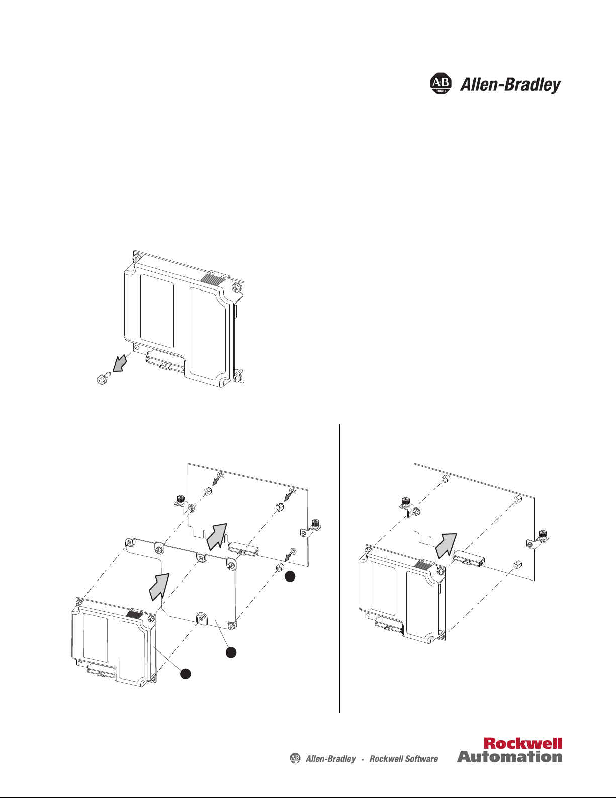
Attach adapter plate
Remove
three standos
Attach communication adapter
(1)
A
B
C
20-750-20COMM Card
(for Frames 2 and higher
PowerFlex 750-Series Drives)
20-750-20COMM-F1 Card
(for Frame 1 only
PowerFlex 750-Series Drives)
(1)
The adapter plate (SK-R1-COMMPLT1-F1) is included with the 20-750-20COMM-F1 card.
However, the adapter plate may be ordered separately and added to the 20-750-20COMM
card to create a 20-750-20COMM-F1 card.
20-750-20COMM and 20-750-20COMM-F1 Communication
Carrier Cards
(Enables a legacy 20-COMM-* adapter to be used with PowerFlex 750-
Step 1
Step 2
Series Drives)
Publication 750COM-IN001E-EN-P - September 2012
Page 2
20-750-20COMM and 20-750-20COMM-F1 Communication Carrier Cards
A
B
C
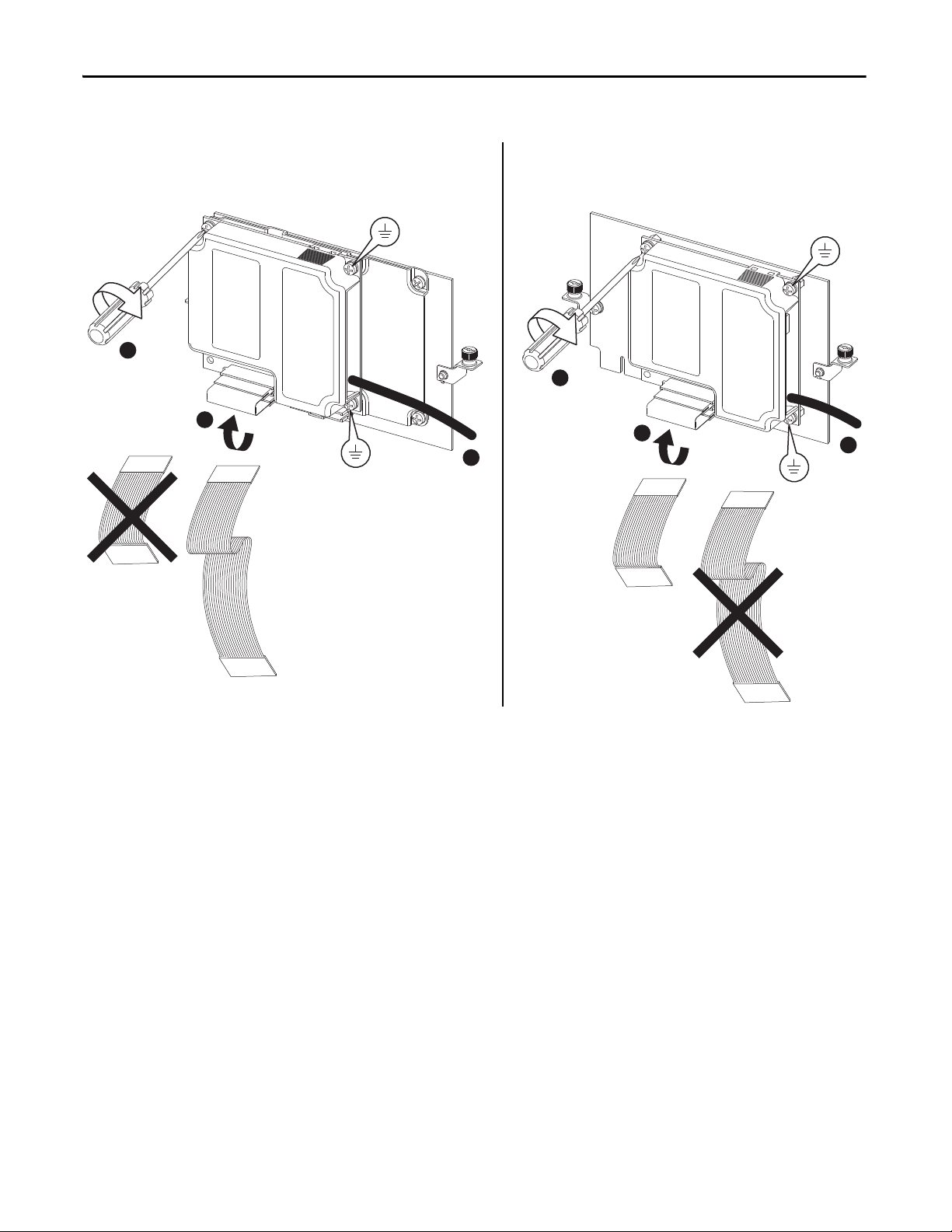
20-750-20COMM Card
(for Frames 2 and higher
PowerFlex 750-Series Drives)
20-750-20COMM-F1 Card
(for Frame 1 only
PowerFlex 750-Series Drives)
A
B
C
0.45…0.67 N•m
(4.0…6.0 lb•in)
3 Places
0.45…0.67 N•m
(4.0…6.0 lb•in)
3 Places
Step 3
2 Rockwell Automation Publication 750COM-IN001E-EN-P - September 2012
Page 3

Step 4
20-750-20COMM Card
(for Frames 2 and higher
PowerFlex 750-Series Drives)
20-750-20COMM-F1 Card
(for Frame 1 only
PowerFlex 750-Series Drives)
NOTE: Port 6 is recommended. Installing the 20-750-20COMM Communication
Carrier Card into Port 4 or Port 5 will make the adjacent left port inaccessible
to other option modules, and may interfere with network cabl e connections.
For more details, contact Allen-Bradley Drives Technical Support.
Important: If a PowerFlex 20-750-PBUS Profibus option module resides in the
adjacent port to the right
of the port in which the Communication Carrier Card is being
installed, the lower mounting screw of the Communication Carrier Card (shown in
DETAIL A above) may electrically contact the metal Profibus cable connector attached
to the Profibus option module. This may cause faulty operation. To prevent this,
perform steps 4-A through 4-C below. If a PowerFlex 20-750-PBUS Profibus option
module is not in that port, disregard these steps and proceed to step 5.
A. Remove the lower mounting screw, a T15 Torx head screw shown in DETAIL A
above, from the Communication Carrier Card.
B. Replace the larger T15 Torx head screw with the smaller T8 Torx head mounting
screw that was shipped as a spare with the PowerFlex 20-750-PBUS Profibus
option module.
C. Proceed to step 5.
TIP
To r emo ve t he ca ptiv e T1 5 Torx head screw, the Communication
Carrier Card must removed to back the screw out of the mounting
clip.
NOTE: Only install the 20-750-20COMM-F1 Communication Carrier Card in Port 4.
Do not install it in Port 5 or Port 6. Installing it into Port 4 will make the
adjacent left Port 5 inaccessible to other option modules, and may interfere
with network cable connections. For more details, contact Allen-Bradley
Drives Technical Support.
20-750-20COMM and 20-750-20COMM-F1 Communication Carrier Cards
DETAIL A
Rockwell Automation Publication 750COM-IN001E-EN-P - September 2012 3
Page 4

20-750-20COMM and 20-750-20COMM-F1 Communication Carrier Cards
20-750-20COMM Card
(for Frames 2 and higher
PowerFlex 750-Series Drives)
20-750-20COMM-F1 Card
(for Frame 1 only
PowerFlex 750-Series Drives)
0.45…0.67 N•m
(4.0…6.0 lb•in)
2 Places
0.45…0.67 N•m
(4.0…6.0 lb•in)
2 Places
Step 5
U.S. Allen-Bradley Drives Technical Support - Tel: (1) 262.512.8176, Fax: (1) 262.512.2222, E-mail: support@drives.ra.rockwell.com
Online: www.ab.com/support/abdrives
Allen-Bradley, Rockwell Software, Rockwell Automation, and TechConnect are trademarks of Rockwell Automation, Inc.
Trademarks not belonging to Rockwell Automation are property of their respec tive companies.
Publication 750COM-IN001E-EN-P - September 2012 PN-169297
Supersedes Publication 750COM-UM001D-EN-P - February 2012 Copyright © 2012 Rockwell Auto mation, Inc. All rights reserved. Pr inted in the U.S.A.
 Loading...