

Page 1
Design Guide
Motor Cables, Interface Cables,
Connector Kits, and Other Drive
Accesso ries
Kinetix 3
Servo Drives
Rotary Motion
Linear Motion
Kinetix 3 Drive Systems
Catalog Numbers 2071-AP0, 2071-AP1, 2071-AP2, 2071-AP4, 2071-AP8, 2071-A10, 2071-A15
Top ic Pag e
Introduction 2
Determine What You Need 3
Kinetix 3 System Examples 4
2090-Series Motor/Actuator Cables Overview 7
Rotary Motion System Combinations
TL-Series (Bulletin TLY) Motors 9
TL-Series (Bulletin TL) Motors 14
Linear Motion System Combinations
LDAT-Series Integrated Linear Thrusters 17
MP-Series Integrated Linear Stages 27
TL-Series Electric Cylinders 29
LDC-Series Linear Motors 32
LDL-Series Linear Motors 36
Additional Resources 40
Page 2

Kinetix 3 Drive Systems
IMPORTANT
Introduction
This publication assumes that your application uses the Kinetix® 3 drive family and that you have already determined your
motor/actuator series. To revisit those decisions, refer to the Kinetix Motion Control Selection Guide, publication
GMC-SG001
The purpose of this publication is to assist you in identifying the drive system components and accessory items you need for
your Kinetix 3 drive and motor/actuator combination. Diagrams in this publication illustrate how many of the common
drive accessory items are used in a typical system, but refer to the Kinetix Motion Accessories Technical Data, publication
GMC-TD004
Also provided are drive/motor or drive/actuator system combinations that include the following:
• Motor/cable combinations table.
• Drive and motor/actuator performance specification table.
• Torque/speed curves with each motor matched to the drive with optimum performance.
Performance specification data and curves reflect nominal system performance of a typical system with motor/drive at
rated ambient temperature and line voltage. For additional information on ambients, line conditions, and valid
combinations not shown in this publication, refer to Motion Analyzer software.
, or Motion Analyzer software.
, for detailed accessory descriptions and specifications.
These system combinations do not include all possible motor/drive combinations. Refer to Motion Analyzer software to verify
compatibility. Download is available at http://www.ab.com/motion/software/analyzer.html
.
2 Rockwell Automation Publication GMC-RM005B-EN-P - September 2013
Page 3

Kinetix 3 Drive Systems
Determine What You Need
For each Kinetix 3 drive system, you need to know the drive and motor/actuator catalog numbers to determine the motor
power and feedback cable catalog numbers. Interface cables and connector kits are also required. Optional equipment
includes Bulletin 2097 AC line filters and others. Example diagrams of the required equipment listed on this page are
shown on page 4
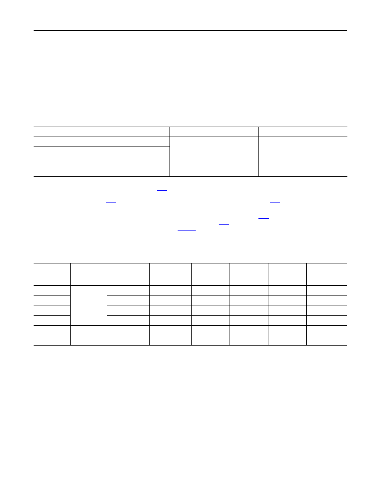
Kinetix 3 Drive Modules
.
Cat. No. Input Voltage Continuous Output Power
2071-AP0
2071-AP1 100 W 1.56
2071-AP2 200 W 2.40
2071-AP2 400 W 4.67
2071-AP8
2071-A10
2071- A15 1.5 kW 13.99
240V AC rms, single-phase
240V AC rms, single-phase
or three-phase
240V AC rms, three phase
50 W 0.85
800 W 7.07
1.0 kW 9.90
Continuous Output Current
A 0-pk
Refer to the Kinetix Servo Drives Specifications Technical Data, publication GMC-TD003, for detailed descriptions and
additional specifications for the Kinetix 3 drive family.
Required Drive Accessories
Drive Accessory Description Cat. No.
Serial interface cable to personal computer for programming. One cable required per computer
Control and configuration serial cables
Drive-mounted breakout boards
(required for flying-lead cables)
Motor power and feedback cables Refer to the specific drive/motor combination for the motor cables required for your system.
(reused with each drive).
Control interface cable to MicroLogix™ programmable logic controller. Required when using
Modbus-RTU control.
20-pin, drive-mounted breakout board for feedback connections. 2071-TBMF
50-pin, drive-mounted breakout board for I/O connections. However, only 24 of the most
commonly used pins are accessible.
2090-CCMPCDS-23AAxx
2090-CCMCNDS-48AAxx
(1)
2071-TBIO
(1) The customer-supplied 3.6V lithium battery, when installed in motor feedback breakout board 2071-TBMF, provides absolute position reference for TL-Series™ (Bulletin TL, TLY, and TLAR) motors
and actuators. Refer to Battery Specifications
.
Battery Specifications
Attribute Value
International size reference 1/2AA, ER14252
Capacity, nom @ 0.5 mA, to 2V 1.2 Ah
Rated voltage 3.6V
Max recommended continuous current 50 mA
Refer to the Kinetix Motion Accessories Technical Data, publication GMC-TD004, for detailed descriptions and
specifications of these servo drive accessories.
Rockwell Automation Publication GMC-RM005B-EN-P - September 2013 3
Page 4
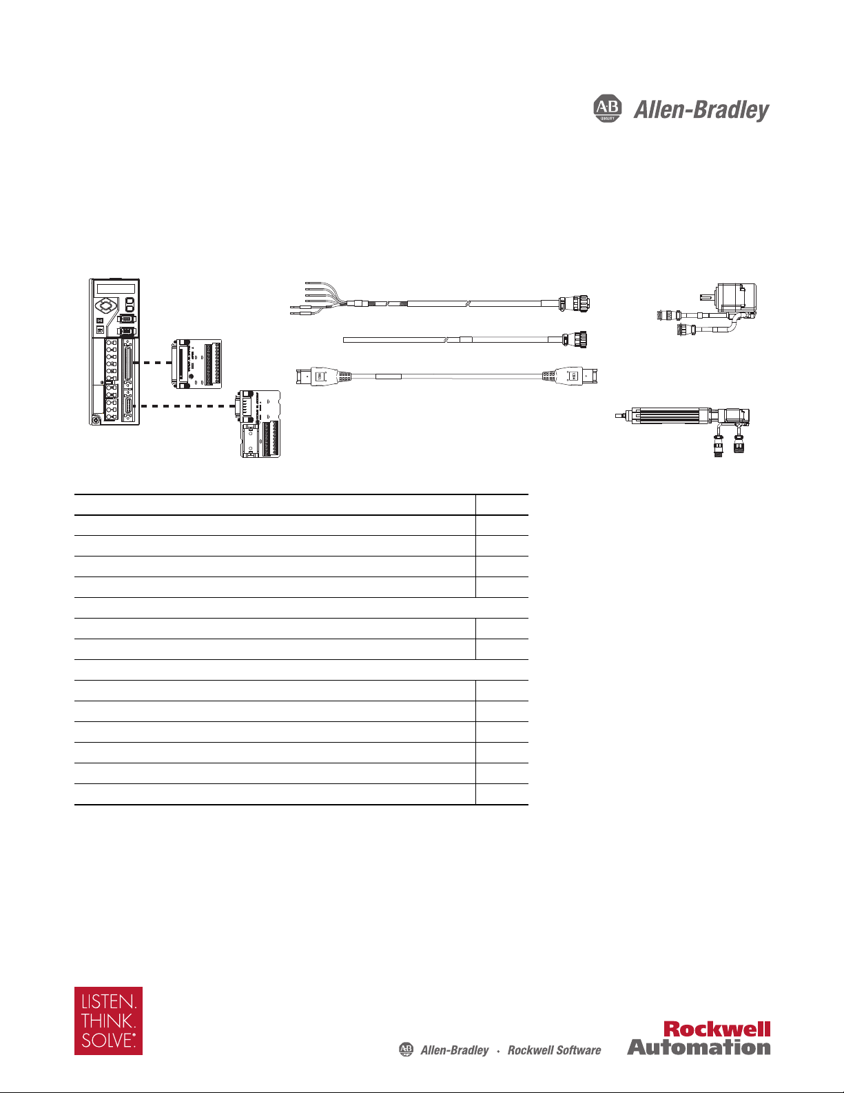
Kinetix 3 Drive Systems
1/2AA
3.6V
2071-Axx
Kinetix 3 Drive
2071-TBMF Motor Feedback
Breakout Board
(shown with battery backup option)
2090-CFBM6DF-CBAAxx
Motor Feedback Cable
2090-CPxM6DF-16AAxx
Motor Power Cable
TL-Series (TLY-Axxxx-x)
Rotary Motors
TL-Series™ (TLAR-Axxxxx)
Electric Cylinders
Battery Backup Requirements
Motor/Actuator Battery Backup
Bulletin TLY Optional
Bulletin TLAR Required
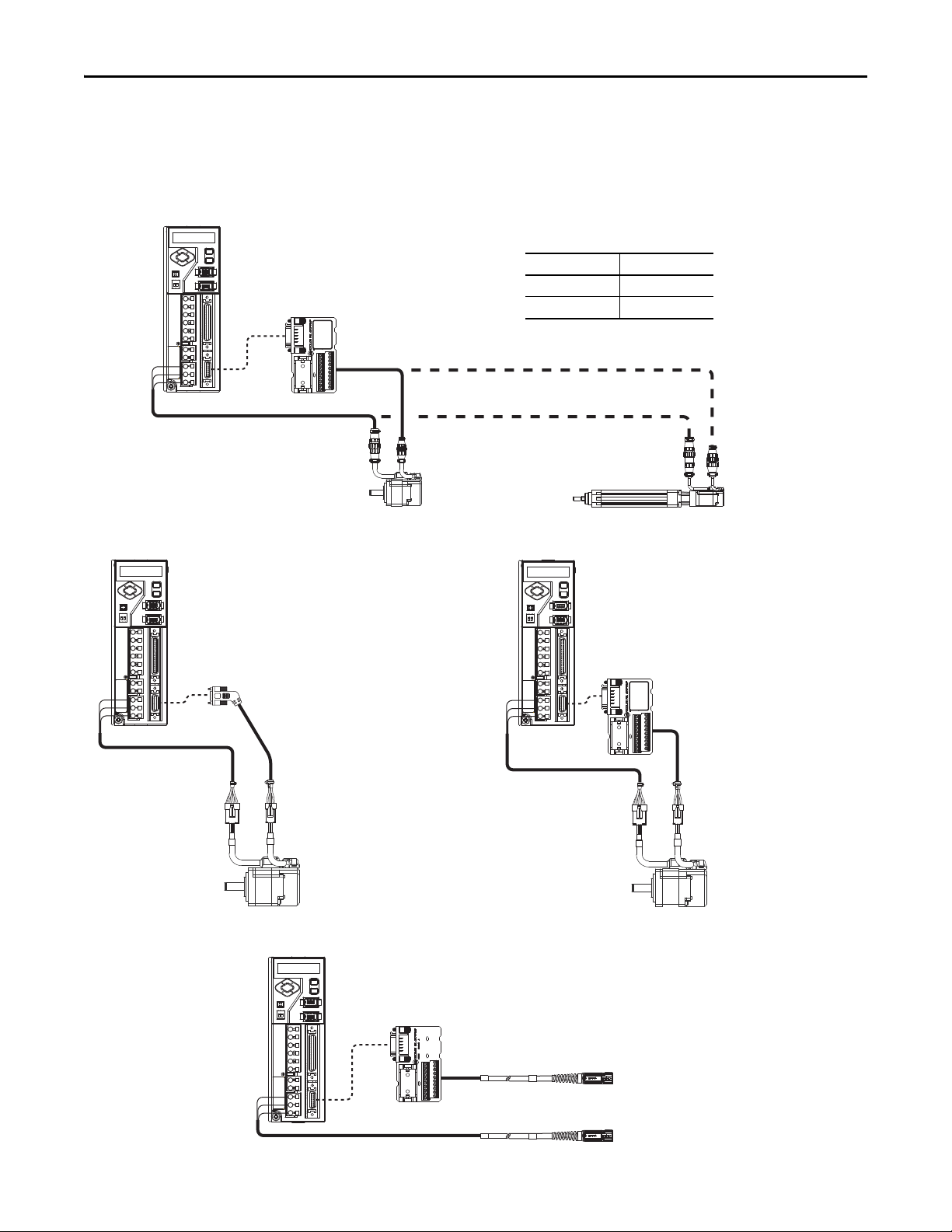
1/2AA
3.6V
2071-Axx
Kinetix 3 Drive
2071-Axx
Kinetix 3 Drive
2071-TBMF Motor Feedback Breakout Board
(battery backup is optional)
2090-DANFCT-Sxx
Motor Feedback Cable
(no battery backup)
2090-DANFCT-Sxx
Motor Feedback Cable
(connector removed)
2090-DANPT-16Sxx
Motor Power Cable
2090-DANPT-16Sxx
Motor Power Cable
TL-Series (TL-Axxxx-B)
Rotary Motors
(high-resolution encoder)
TL-Series (TL-Axxxx-B)
Rotary Motors
(high-resolution encoder)
2071-Axx
Kinetix 3 Drive
2071-TBMF Motor Feedback Breakout Board
(battery backup not required)
Bulletin 2090 Motor Feedback Cable
Bulletin 2090 Motor Power Cable
Kinetix 3 System Examples
These system examples illustrate how the drive modules and accessories are used in typical configurations.
Kinetix 3 Motor Feedback Example (Bulletin TLY rotary motors or TLAR electric cylinders)
Kinetix 3 Motor Feedback Example (Bulletin TL motors)
Kinetix 3 Motor Feedback Example (Bulletin MPAS, LDAT-Series, LDC-Series, and LDL-Series)
4 Rockwell Automation Publication GMC-RM005B-EN-P - September 2013
Page 5
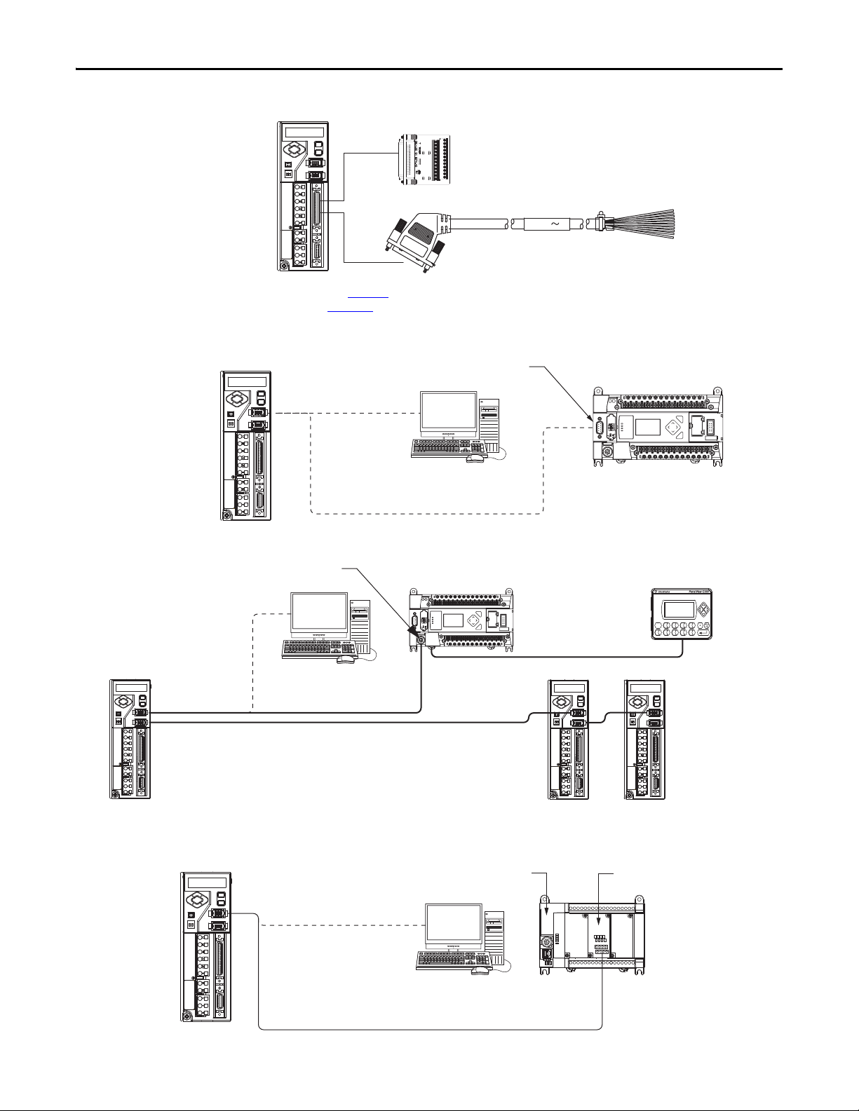
Kinetix 3 I/O Wiring Options
2071-Axx
Kinetix 3 Drive
2071-TBIO
(1)
Limited I/O Breakout Board
(provides access to 24 of the most commonly used terminals)
2090-DAIO-D50xx
(2)
Full Breakout (50-pin, flying-lead) I/O Cable
(provides access to all 50 terminals)
2071-Axx
Kinetix 3 Drive
1766-L32xxx
MicroLogix 1400
Control ler
2090-CCMPCDS-23AAxx
Programming Cable
(programming only)
Ultraware Software
(version 1.80 or later)
ASCII (RS-232C)
Communication Port
ESC
OK
F11F22F33F44F5
5
F66F77F88F99F10
0
2071-Axx
Kinetix 3 Drive
2090-CCMCNDS-48AAxx
Controller Cable
RSLogix 500 Software
1766-L32xxx
MicroLogix 1400 Controller
(1)
2071-Axx
Kinetix 3 Drives
2090-CCMDSDS-48AAxx
Drive-to-Drive Cables
2090-CCMPCDS-23AAxx
Programming Cable (programming only)
Non-isolated
Serial Communication Port
PanelView Component
Display Terminal
1585J-M8CBJM-x Ethernet Cable
2071-Axx
Kinetix 3 Drive
Remove cable connector and
wire flying-leads to serial
communication module.
2080-SERIALISOL
Isolated Serial Communication Module
2090-CCMPCDS-23AAxx
Programming Cable (programming only)
2090-CCMCNDS-48AAxx
Control ler Cable
Connected Components
Work shop S oftw are
2080-L30xxxxx
Micro830™ Programmable Controller (24-point is shown)
(1) Refer to Kinetix 3 I/O Breakout Board Installation Instructions, publication 2071-IN002, for pinout information. No I/O wiring is needed with serial communication control.
(2) Refer to Kinetix 3 Component Servo Drives User Manual, publication 2071-UM001
, for pinout information. No I/O wiring is needed with serial communication control.
Kinetix 3 Configuration (ASCII control)
Kinetix 3 Drive Systems
ESC
OK
Kinetix 3 Configuration (Modbus control)
(1) Could also be MicroLogix 1100 controller (catalog number 1763-L16xxx).
Kinetix 3 Configuration (2080-SERIALISOL communication module)
Rockwell Automation Publication GMC-RM005B-EN-P - September 2013 5
Page 6
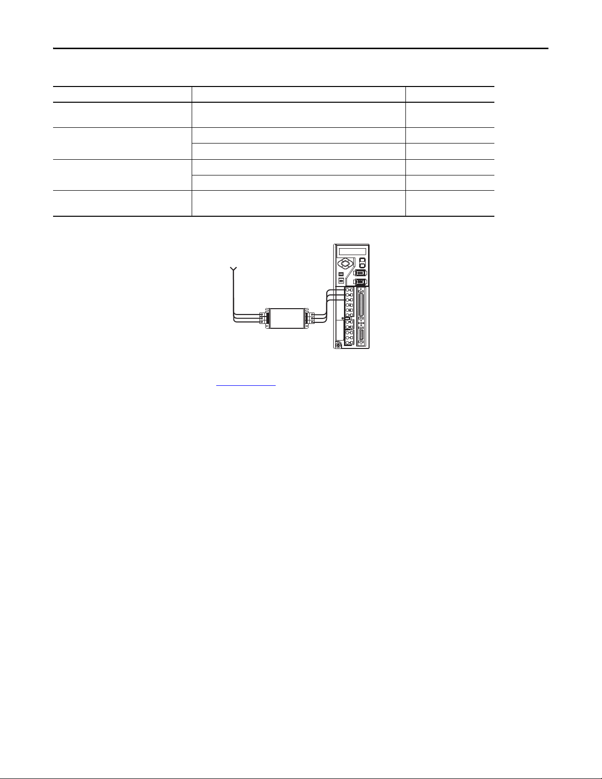
Kinetix 3 Drive Systems
Single-phase or Three-phase
Input Power
Kinetix 3
Servo Drive
2090-XXLF-TCxxx
AC Lin e Filter
(optional equipment)
Optional Drive Accessories
Drive Accessory Description Cat. No.
I/O cable (applies to flying-lead cables as an
alternative to drive-mounted breakout boards)
Control and configuration serial cables
2090 AC line filter
Connector set
50-pin, flying-lead cable for I/O (IOD) connections 2090-DAIO-D50xx
Control interface cable for drive-to-drive configurations 2090-CCMDSDS-48AAxx
Control interface cable for drive-to-1203-USB converter 2090-CCMUSDS-48AAxx
250V AC, 50/60 Hz, single-phase 2090-XXLF-TC116
520V AC, 50/60 Hz, three-phase 2090-XXLF-TC316
Replacement connectors for general purpose input power (IPD), shunt
resistor (BC), and motor power (MP)
2071-CONN1
Kinetix 3 Input Power Accessories Example
Motor-end cable connector kits, for use when building your own cables, are also available. Refer to the Kinetix Motion
Accessories Technical Data, publication GMC-TD004
, for detailed descriptions and specifications of servo drive
accessories.
6 Rockwell Automation Publication GMC-RM005B-EN-P - September 2013
Page 7
2090-Series Motor/Actuator Cables Overview
IMPORTANT
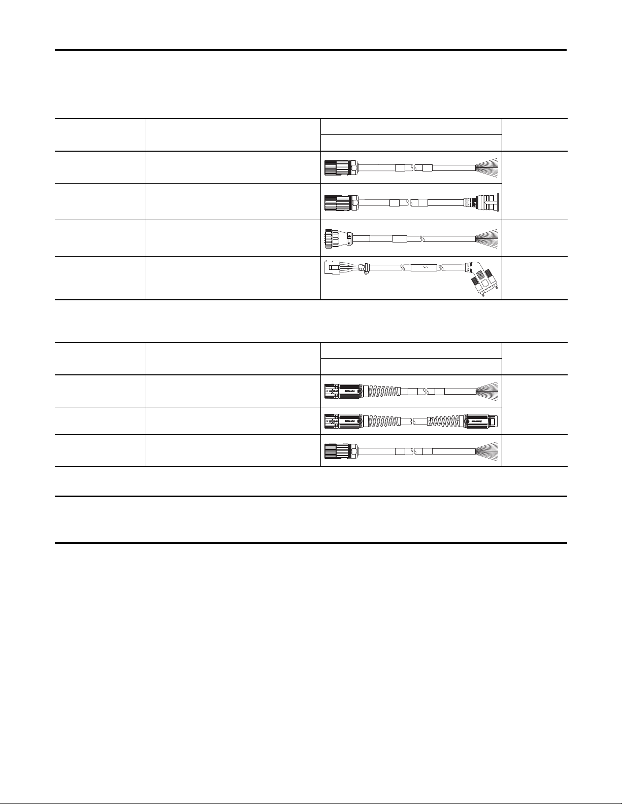
Feedback Cable Descriptions (standard, non-flex)
Kinetix 3 Drive Systems
Standard Cable
Cat. No.
2090-XXNFMF-Sxx
2090-CFBM4E2-CATR
2090-CFBM6DF-CBAAxx
2090-DANFCT-Sxx
(1) Threaded DIN connector (motor end) and bayonet connector for 2090-XXNFMP-Sxx cable.
Description
• Drive-end flying-leads
• High-resolution or incremental applications
• Drive-end bayonet (E2), transition (TR) cable
• Motor-end threaded DIN (M4)
• All feedback types (CA)
• Drive-end flying-leads (DF)
• High-resolution, battery backup or
Incremental applications (CB)
• Drive-end 20-pin connector
• High-resolution applications
Feedback Cable Descriptions (continuous-flex)
Continuous-flex Cable
Cat. No.
2090-CFBM7DF-CDAFxx
2090-CFBM7E7-CDAFxx
Description
• Drive-end flying-leads (DF)
• High-resolution or incremental applications (CD)
• Drive-end (male) connector, extension (E7)
• Motor-end SpeedTec DIN cable plug (M7)
(1)
Cable Configuration
Motor/Actuator End Drive End
(1)
Cable Configuration
Motor/Actuator End Drive End
Motor/Actuator
Connector
Threaded DIN
(M4)
Circular Plastic
(M6)
Rectangular Plastic
Motor/Actuator
Connector
SpeedTec DIN
(M7)
2090-CFBM4DF-CDAFxx
(1) SpeedTec DIN connector (motor end) and male connector for extending SpeedTec or threaded DIN cable.
• Drive-end flying-leads
• High-resolution or incremental applications
Feedback cables with the CE designation, for example 2090-CFBM7DF-CEAAxx, are intended for high-resolution encoder or
resolver applications and have fewer conductors than feedback cables with the CD designation, for example
2090-CFBM7DF-CDAFxx, which are intended for high-resolution or incremental encoder applications.
Threaded DIN
(M4)
Rockwell Automation Publication GMC-RM005B-EN-P - September 2013 7
Page 8
Kinetix 3 Drive Systems
BR+
BR-
BR+
BR-
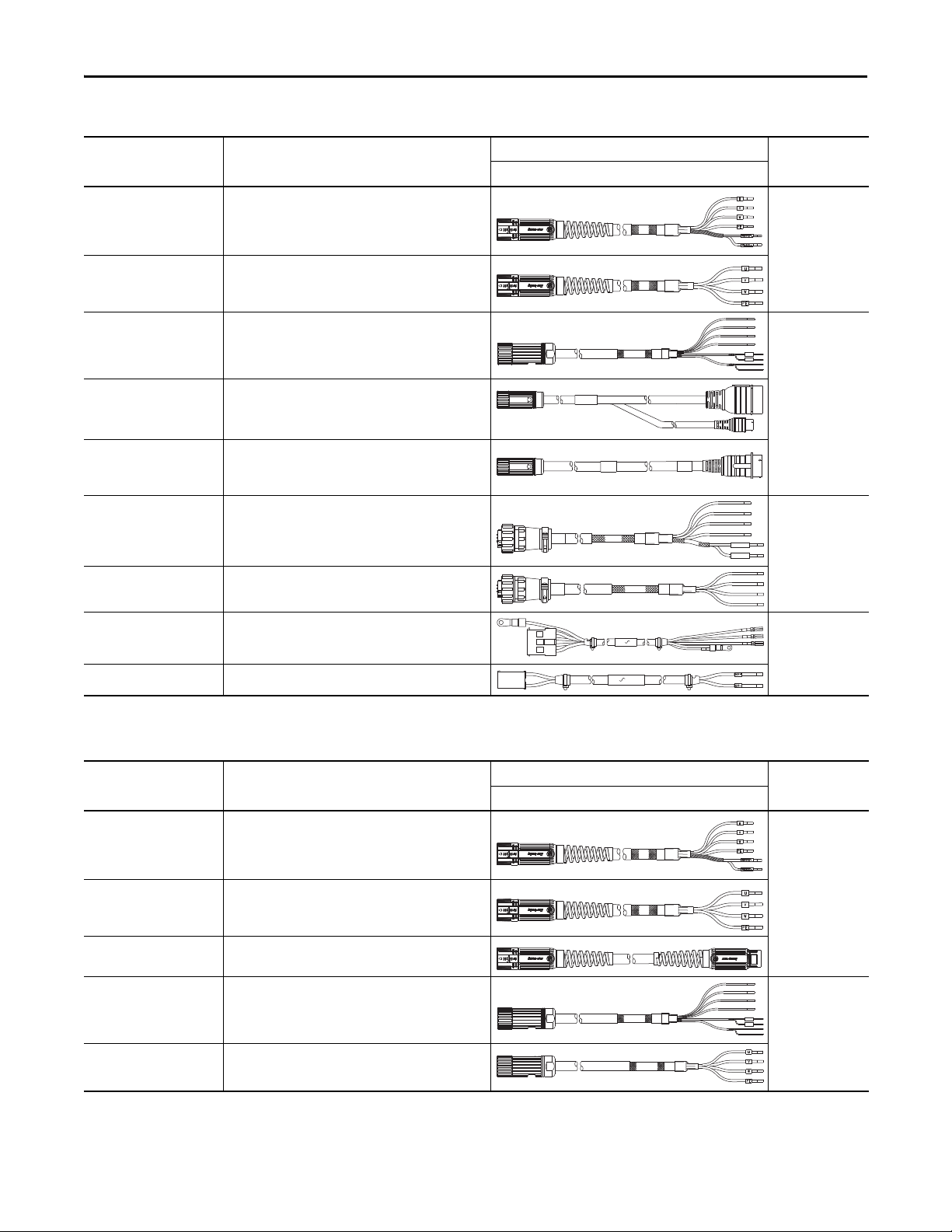
Power/Brake Cable Descriptions (standard, non-flex)
Standard Cable
Cat. No.
2090-CPBM7DF-xxAAxx
2090-CPWM7DF-xxAAxx
2090-XXNPMF-xxSxx
2090-CPBM4E2-xxTR
2090-CPWM4E2-xxTR
2090-CPBM6DF-16AAxx
2090-CPWM6DF-16AAxx
Description
• Drive-end flying-leads (DF)
• Power /brake wires (PB)
• Drive-end flying-leads (DF)
• Power wires only (PW)
• Drive-end flying-leads
• Power /brake wires
• Drive-end bayonet (E2), transition (TR) cable
• Motor-end threaded DIN (M4)
• Power /brake wires (PB)
• Drive-end bayonet (E2), transition (TR) cable
• Motor-end threaded DIN (M4)
• Power wires only (PW)
• Drive-end flying-leads (DF)
• Power /brake wires (PB)
• Drive-end flying-leads (DF)
• Power wires only (PW)
Cable Configuration
Motor/Actuator End Drive End
Motor/Actuator
Connector
SpeedTec DIN
(M7)
(1)
Threaded DIN
(M4)
(1)
MBRK+
Circular Plastic
MBRK-
(M6)
2090-DANPT-16Sxx
• Drive-end flying-leads
• Power wires only
2090-DANBT-18Sxx Drive-end flying-lead brake wires
(1) Threaded DIN connector (motor end) and bayonet connector for 2090-XXNFMP-Sxx cable.
Power/Brake Cable Descriptions (continuous-flex)
Continuous-flex Cable
Cat. No.
2090-CPBM7DF-xxAFxx
2090-CPWM7DF-xxAFxx
2090-CPBM7E7-xxAFxx
2090-CPBM4DF-xxAFxx
2090-CPWM4DF-xxAFxx
Description
• Drive-end flying-leads (DF)
• Power /brake wires (PB)
• Drive-end flying-leads (DF)
• Power wires only (PW)
• Drive-end (male) connector, extension (E7)
• Motor-end SpeedTec DIN cable plug (M7)
• Drive-end flying-leads (DF)
• Power /brake wires (PB)
• Drive-end flying-leads (DF)
• Power wires only (PW)
(1)
Cable Configuration
Motor/Actuator End Drive End
Rectangular Plastic
Motor/Actuator
Connector
SpeedTec DIN
(M7)
Threaded DIN
(M4)
(1) SpeedTec DIN connector (motor end) and male connector for extending SpeedTec or threaded DIN cable.
8 Rockwell Automation Publication GMC-RM005B-EN-P - September 2013
Page 9
Kinetix 3 Drive Systems
Kinetix 3 (200V-class) Drives with TL-Series (Bulletin TLY) Low Inertia Motors
This section provides system combination information for the Kinetix 3 drives when matched with TL-Series
(BulletinTLY) low-inertia motors. Compatible TL-Series motors are equipped with absolute high-resolution or
incremental encoder feedback. Included are motor power/brake and feedback cable catalog numbers, system performance
specifications, and the optimum torque/speed curves.
Bulletin TLY Motor Cable Combinations
Motor Cat. No. Motor Power/Brake Cable Motor Feedback Cable
TLY-A120x, TLY-A130x
TLY-A220x, TLY-A230x
TLY-A2540P
TLY-A310M
(1) For TLY-Axxxx-H motors with incremental encoder feedback, use 2090-CFBM6DF-CBAAxx flying-lead cables and 2071-TBMF connector kit (battery not required) on the drive end. Refer to Kinetix 3 Motor
Feedback Example (Bulletin TLY rotary motors or TLAR electric cylinders) on page 4
TLY-Axxxx-B motors with 17-bit high resolution encoder feedback require the 2090-CFBM6DF-CBAA xx flying-lead feedback cable and 2071-TBMF connector kit with customer-supplied 3.6V lithium
battery. Refer to Battery Specifications on page 3
TL-Series (Bulletin TLY) motors are characterized as having 1000 mm (39.4 in.) cable extensions with circular plastic connectors and TLY-Axxx catalog numbers.
For cable configuration illustrations and feature descriptions, by catalog number, refer to 2090-Series Motor/Actuator Cables Overview beginning on page 7
Motor-end connector kits are available for motor power/brake and feedback cables. Refer to Optional Drive Accessories on page 6
Cable len gth xx is in meters. Refer to the Kinetix Motion Accessories Technical Data, publication GMC-TD004
. Refer to Kinetix 3 Mo tor Feedback Example (Bulletin TLY rotary motors or TLAR electric cylinders) on page 4 for more information.
2090-CPWM6DF-16AAxx (standard, non-flex)
(without brake)
2090-CPBM6DF-16AAxx (standard, non-flex)
(with brake)
for more information.
.
, for standard cable lengths.
2090-CFBM6DF-CBAAxx or (standard, non-flex)
Absolute High-resolution or Incremental
Feedba ck
.
(1)
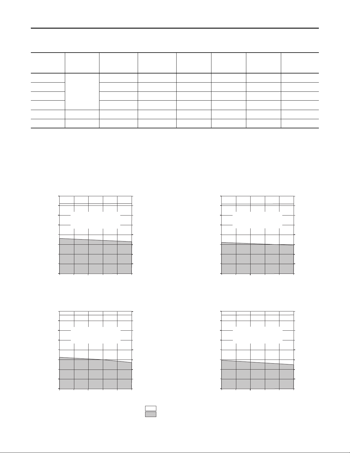
Bulletin TLY (non-brake) Motor Performance Specifications with Kinetix 3 (200V-class) Drives
Rotary Motor
TLY-A120x
TLY-A130x 1.85 0.325 (2.88) 4.90 0.76 (6.70) 0.14 2071-AP1
TLY-A220x 3.50 0.836 (7.40) 7.90 1.48 (13.1) 0.35 2071-AP4
TLY-A230x 5.50 1.30 (11.5) 15.5 3.05 (27.0) 0.44 2071-AP4
TLY-A2540P 5000 10.0 2.94 (26.0) 24.8 7.10 (63.0) 0.86 2071-AP8
TLY-A310M 4500 10.0 3.61 (31.9) 30.0 9.0 (79.6) 0.95 2071-A10
Speed, max
rpm
(1)
6000
System Continuous
Stall Current
A 0-pk
1.03 0.181 (1.60) 2.50 0.36 (3.20) 0.086 2071-AP1
System Continuous
Stall Torque
N•m (lb•in)
System Peak
Stall Current
A 0-pk
System Peak
Tor que
N•m (lb•in)
Motor Rated
Output
kW
Kinetix 3
200V-class Drives
(1) Applies to TLY-AxxxT-H motors with incremental feedback. The TLY-AxxxP-B motors with absolute high-resolution encoders are rated at 5000 rpm.
Performance specification data and curves reflect nominal sys tem performance of a typical system with motor at 40 °C (104 °F) and drive at 50 °C (122 °F) ambient and rated line voltage. For additional
information on ambient and line conditions, refer to Motion Analyzer software.
Rockwell Automation Publication GMC-RM005B-EN-P - September 2013 9
Page 10
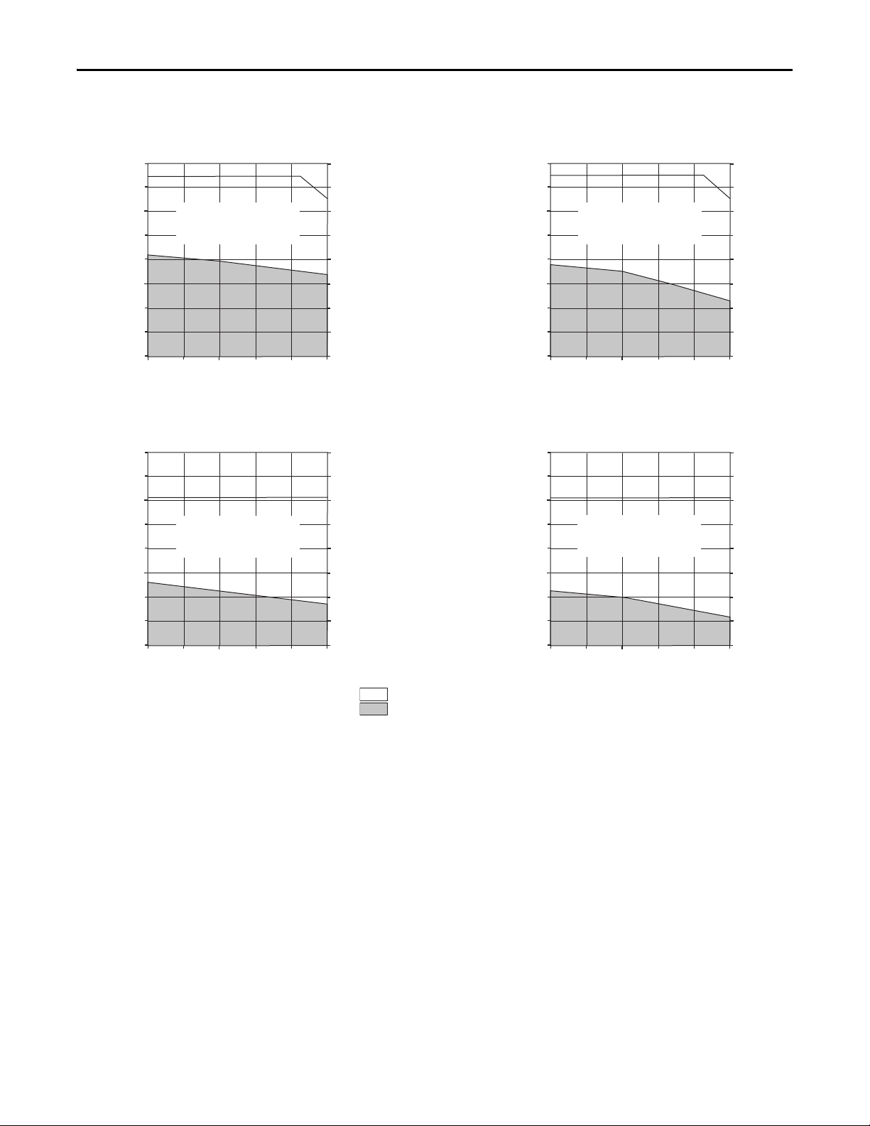
Kinetix 3 Drive Systems
Torque
(N•m)
Torque
(lb•in)
Speed (rpm)
2071-AP1 and TLY-A120P-B
0
3000
5000
0.400
0.350
0.300
0.250
0.200
0.150
0.100
0.050
0
40001000
2000
3.54
3.10
2.65
2.21
1.77
1.33
0.88
0.44
0
Intermittent curve represents
single-phase input.
Torque
(N•m)
Torque
(lb•in)
Speed (rpm)
2071-AP1 and TLY-A130P-B
0
3000
5000
0.800
0.700
0.600
0.500
0.400
0.300
0.200
0.100
0
40001000
2000
7.08
6.19
5.31
4.42
3.54
2.65
1.77
0.88
0
Intermittent curve represents
single-phase input.
= Intermittent operating region
= Continuous operating region
Bulletin TLY (brake) Motor Performance Specifications with Kinetix 3 (200V-class) Drives
Rotary Motor
Speed, max
rpm
TLY-A120x
TLY-A130x 1.67 0.293 (2.59) 4.90 0.76 (6.70) 0.13 2071-AP1
TLY-A220x 3.15 0.757 (6.70) 7.90 1.48 (13.1) 0.24 2071-AP4
6000
(1)
System Continuous
Stall Current
A 0-pk
0.93 0.163 (1.44) 2.50 0.36 (3.20) 0.077 2071-AP1
System Continuous
Stall Torque
N•m (lb•in)
System Peak
Stall Current
A 0-pk
System Peak
Tor que
N•m (lb•in)
Motor Rated
Output
kW
Kinetix 3
200V-class Drives
TLY-A230x 4.95 1.16 (10.3) 15.5 3.05 (27.0) 0.32 2071-AP4
TLY-A2540P 5000 10.0 2.94 (26.0) 24.8 7.10 (63.0) 0.66 2071-AP8
TLY-A310M 4500 10.0 3.61 (31.9) 30.0 9.0 (79.6) 0.90 2071-A10
(1) Applies to TLY-AxxxT-H motors with incremental feedback. The TLY-AxxxP-B motors with absolute high-resolution encoders are rated at 5000 rpm.
Performance specification data and curves reflect nominal sys tem performance of a typical system with motor at 40 °C (104 °F) and drive at 50 °C (122 °F) ambient and rated line voltage. For additional
information on ambient and line conditions, refer to Motion Analyzer software.
Kinetix 3 (200V-class) Drives/TLY-AxxxP-B (absolute high-resolution) Motor Curves
2071-AP1 and TLY-A120P-B (Brake)
Torque
(N•m)
0.400
0.350
0.300
0.250
0.200
0.150
0.100
0.050
Intermittent curve represents
single-phase input.
0
0
2000
3000
40001000
Speed (rpm)
3.54
3.10
2.65
2.21
1.77
1.33
0.88
0.44
0
5000
Torque
(lb•in)
Torque
(N•m)
10 Rockwell Automation Publication GMC-RM005B-EN-P - September 2013
0.800
0.700
0.600
0.500
0.400
0.300
0.200
0.100
2071-AP1 and TLY-A130P-B (Brake)
Intermittent curve represents
single-phase input.
0
0
2000
Speed (rpm)
3000
7.08
Torque
(lb•in)
6.19
5.31
4.42
3.54
2.65
1.77
0.88
0
5000
40001000
Page 11
Kinetix 3 Drive Systems
Torque
(N•m)
Torque
(lb•in)
Speed (rpm)
2071-AP4 and TLY-A220P-B
0
3000
5000
1.600
1.400
1.200
1.000
0.800
0.600
0.400
0.200
0
40001000
2000
14.1
12.4
10.6
8.85
7.08
5.31
3.54
1.77
0
Intermittent curve represents
single-phase input.
Torque
(N•m)
Torque
(lb•in)
Speed (rpm)
2071-AP4 and TLY-A230P-B
0
3000
5000
4.00
3.50
3.00
2.50
2.00
1.50
1.00
0.50
0
40001000
2000
35.4
31.0
26.5
22.1
17.7
13.3
8.85
4.42
0
Intermittent curve represents
single-phase input.
= Intermittent operating region
= Continuous operating region
Kinetix 3 (200V-class) Drives/TLY-AxxxP-B (absolute high-resolution) Motor Curves (continued)
2071-AP4 and TLY-A220P-B (Brake)
1.600
Torque
(N•m)
1.400
Torque
(N•m)
1.200
1.000
0.800
0.600
0.400
0.200
0
0
4.00
3.50
3.00
2.50
2.00
1.50
1.00
0.50
0
0
Intermittent curve represents
single-phase input.
3000
2000
40001000
Speed (rpm)
2071-AP4 and TLY-A230P-B (Brake)
Intermittent curve represents
single-phase input.
3000
2000
40001000
Speed (rpm)
5000
5000
14.1
12.4
10.6
8.85
7.08
5.31
3.54
1.77
0
35.4
31.0
26.5
22.1
17.7
13.3
8.85
4.42
0
Torque
(lb•in)
Torque
(lb•in)
Rockwell Automation Publication GMC-RM005B-EN-P - September 2013 11
Page 12
Kinetix 3 Drive Systems
0
3000
5000
40001000
2000
6000
Torque
(N•m)
Torque
(lb•in)
Speed (rpm)
2071-AP1 and TLY-A120T-H
0.400
0.350
0.300
0.250
0.200
0.150
0.100
0.050
0
3.54
3.10
2.65
2.21
1.77
1.33
0.88
0.44
0
Intermittent curve represents
single-phase input.
Torque
(N•m)
Torque
(lb•in)
Speed (rpm)
2071-AP1 and TLY-A130T-H
0.800
0.700
0.600
0.500
0.400
0.300
0.200
0.100
0
7.08
6.19
5.31
4.42
3.54
2.65
1.77
0.88
0
0
3000
5000
40001000
2000
6000
Intermittent curve represents
single-phase input.
Torque
(N•m)
Torque
(lb•in)
Speed (rpm)
2071-AP4 and TLY-A220T-H
1.600
1.400
1.200
1.000
0.800
0.600
0.400
0.200
0
14.1
12.4
10.6
8.85
7.08
5.31
3.54
1.77
0
0
3000
5000
40001000
2000
6000
Intermittent curve represents
single-phase input.
= Intermittent operating region
= Continuous operating region
Kinetix 3 (200V-class) Drives/TLY-AxxxT-H (incremental) Motor Curves
0.400
Torque
(N•m)
0.350
0.300
0.250
0.200
0.150
0.100
0.050
0.800
Torque
(N•m)
0.700
0.600
0.500
0.400
0.300
0.200
0.100
2071-AP1 and TLY-A120T-H (Brake)
Intermittent curve represents
single-phase input.
0
0
2000
3000
Speed (rpm)
2071-AP1 and TLY-A130T-H (Brake)
Intermittent curve represents
single-phase input.
0
0
2000
3000
Speed (rpm)
3.54
Torque
(lb•in)
3.10
2.65
2.21
1.77
1.33
0.88
0.44
0
5000
40001000
6000
7.08
6.19
Torque
(lb•in)
5.31
4.42
3.54
2.65
1.77
0.88
0
5000
40001000
6000
Torque
(N•m)
12 Rockwell Automation Publication GMC-RM005B-EN-P - September 2013
1.600
1.400
1.200
1.000
0.800
0.600
0.400
0.200
2071-AP4 and TLY-A220T-H (Brake)
Intermittent curve represents
single-phase input.
0
0
2000
Speed (rpm)
3000
14.1
Torque
(lb•in)
12.4
10.6
8.85
7.08
5.31
3.54
1.77
0
5000
40001000
6000
Page 13
Kinetix 3 (200V-class) Drives/TLY-AxxxT-H (incremental) Motor Curves (continued)
Torque
(N•m)
Torque
(lb•in)
Speed (rpm)
2071-AP4 and TLY-A230T-H
4.00
3.50
3.00
2.50
2.00
1.50
1.00
0.50
0
35.4
31.0
26.5
22.1
17.7
13.3
8.85
4.42
0
0
3000
5000
40001000
2000
6000
Intermittent curve represents
single-phase input.
= Intermittent operating region
= Continuous operating region
Torque
(N•m)
Torque
(lb•in)
Speed (rpm)
2071-AP8 and TLY-A2540P-x
0
3000
5000
8.00
7.00
6.00
5.00
4.00
3.00
2.00
1.00
0
40001000
2000
70.8
61.9
53.1
44.2
35.4
26.5
17.7
88.5
0
Intermittent curve represents
three-phase and single-phase inputs.
Torque
(N•m)
Torque
(lb•in)
2071-A10 and TLY-A310M-x
Speed (rpm)
0
2000
4000
30001000
5000
12.0
10.0
8.0
6.0
4.0
2.0
0
106
88.5
70.8
53.1
35.4
17.7
0
Intermittent curve represents
three-phase input.
= Intermittent operating region
= Continuous operating region
2071-AP4 and TLY-A230T-H (Brake)
(N•m)
4.00
3.50
Torque
3.00
2.50
2.00
Intermittent curve represents
single-phase input.
1.50
1.00
0.50
0
0
2000
Speed (rpm)
Kinetix 3 (200V-class) Drives/TLY-Axxxx-x Motor Curves
3000
5000
40001000
Kinetix 3 Drive Systems
35.4
Torque
(lb•in)
31.0
26.5
22.1
17.7
13.3
8.85
4.42
0
6000
2071-AP8 and TLY-A2540P-x (Brake)
(N•m)
8.00
7.00
6.00
5.00
Intermittent curve represents
three-phase and single-phase inputs.
Torque
4.00
3.00
2.00
1.00
0
0
2000
3000
40001000
Speed (rpm)
2071-A10 and TLY-A310M-x (Brake)
12.0
Torque
(N•m)
10.0
8.0
0
0
Intermittent curve represents
three-phase input.
30001000
2000
Speed (rpm)
4000
5000
6.0
Rockwell Automation Publication GMC-RM005B-EN-P - September 2013 13
4.0
2.0
5000
106
88.5
70.8
53.1
35.4
17.7
0
70.8
61.9
53.1
44.2
35.4
26.5
17.7
88.5
0
Torque
(lb•in)
Torque
(lb•in)
Page 14

Kinetix 3 Drive Systems
Kinetix 3 (200V-class) Drives with TL-Series (Bulletin TL) Low Inertia Motors
This section provides system combination information for the Kinetix 3 servo drives when matched with TL-Series
(Bulletin TL) low-inertia motors. Bulletin TL-Axxx motors are equipped with absolute high-resolution encoder feedback
and are characterized as having 300 mm (11.8 in.) cable extensions with rectangular connectors. Included in this section are
motor power, feedback, and brake cable catalog numbers, system performance specifications, and the optimum torque/
speed curves.
Bulletin TL Motor Cable Combinations
Motor Cat. No. Motor Power Cable Motor Feedback Cable
TL-A120P, TL-A130P
TL-A220P, TL-A230P
TL-A2540P
TL-A410M
(1) TL-Series (Bulletin TL) rotary motors require the 2071-TBMF breakout board with 3.6V lithium battery (not included) for multi-turn high-resolution encoder operation or when using an overtravel limit
switch. To meet this requirement, remove the drive-end connector and wire the 2090-DANFCT-Sxx cable to the 2071-TBMF breakout board. Refer to Kinetix 3 Motor Feedback Example (Bulletin TL motors)
for more information.
on page 4
For cable configuration illustrations and feature descriptions, by catalog number, refer to 2090-Series Motor/Actuator Cables Overview beginning on page 7.
Cable len gth xx is in meters. Refer to the Kinetix Motion Accessories Technical Data, publication GMC-TD004
2090-DANPT-16Sxx
, for standard cable lengths.
2090-DANFCT-Sxx
Absolute High-resolution
(1)
Motor Brake Cable
2090-DANBT-18Sxx
Bulletin TL (non-brake) Performance Specifications with Kinetix 3 (200V-class) Drives
Rotary Motor
TL-A120P
TL-A130P 1.85 0.325 (2.88) 4.90 0.76 (6.70) 0.14 2071-AP1
TL-A220P 3.50 0.836 (7.40) 7.90 1.48 (13.1) 0.35 2071-AP4
TL-A230P 5.50 1.30 (11.5) 15.5 3.05 (27.0) 0.44 2071-AP4
TL-A2540P 10.0 2.94 (26.0) 24.8 7.10 (63.0) 0.86 2071-AP8
TL-A410M 4500 15.5 5.42 (48.0) 43.4 13.0 (115.0) 2.0 2071-A15
Performance specification data and curves reflect nominal sys tem performance of a typical system with motor at 40 °C (104 °F) and drive at 50 °C (122 °F) ambient and rated line voltage. For additional
information on ambient and line conditions, refer to Motion Analyzer software.
Speed, max
rpm
5000
System Continuous
Stall Current
A 0-pk
1.03 0.181 (1.60) 2.50 0.36 (3.20) 0.086 2071-AP1
System Continuous
Stall Torque
N•m (lb•in)
System Peak
Stall Current
A 0-pk
System Peak
Tor que
N•m (lb•in)
Motor Rated
Output
kW
Kinetix 3
200V-class Drives
Bulletin TL (brake) Performance Specifications with Kinetix 3 (200V-class) Drives
Rotary Motor
TL-A120P
TL-A130P 1.67 0.293 (2.59) 4.90 0.76 (6.70) 0.13 2071-AP1
TL-A220P 3.15 0.757 (6.70) 7.90 1.48 (13.10) 0.24 2071-AP4
TL-A230P 4.95 1.160 (10.30) 15.5 3.05 (27.0) 0.32 2071-AP4
TL-A2540P 10.0 2.940 (26.00) 24.8 7.10 (63.0) 0.66 2071-AP8
TL-A410M 4500 14.0 4.860 (43.0) 43.4 13.0 (115.0) 1.80 2071-A15
Performance specification data and curves reflect nominal sys tem performance of a typical system with motor at 40 °C (104 °F) and drive at 50 °C (122 °F) ambient and rated line voltage. For additional
information on ambient and line conditions, refer to Motion Analyzer software.
14 Rockwell Automation Publication GMC-RM005B-EN-P - September 2013
Speed, max
rpm
5000
System Continuous
Stall Current
A 0-pk
0.93 0.163 (1.44) 2.50 0.36 (3.20) 0.077 2071-AP1
System Continuous
Stall Torque
N•m (lb•in)
System Peak
Stall Current
A 0-pk
System Peak
Tor que
N•m (lb•in)
Motor Rated
Output
kW
Kinetix 3
200V-class Drives
Page 15

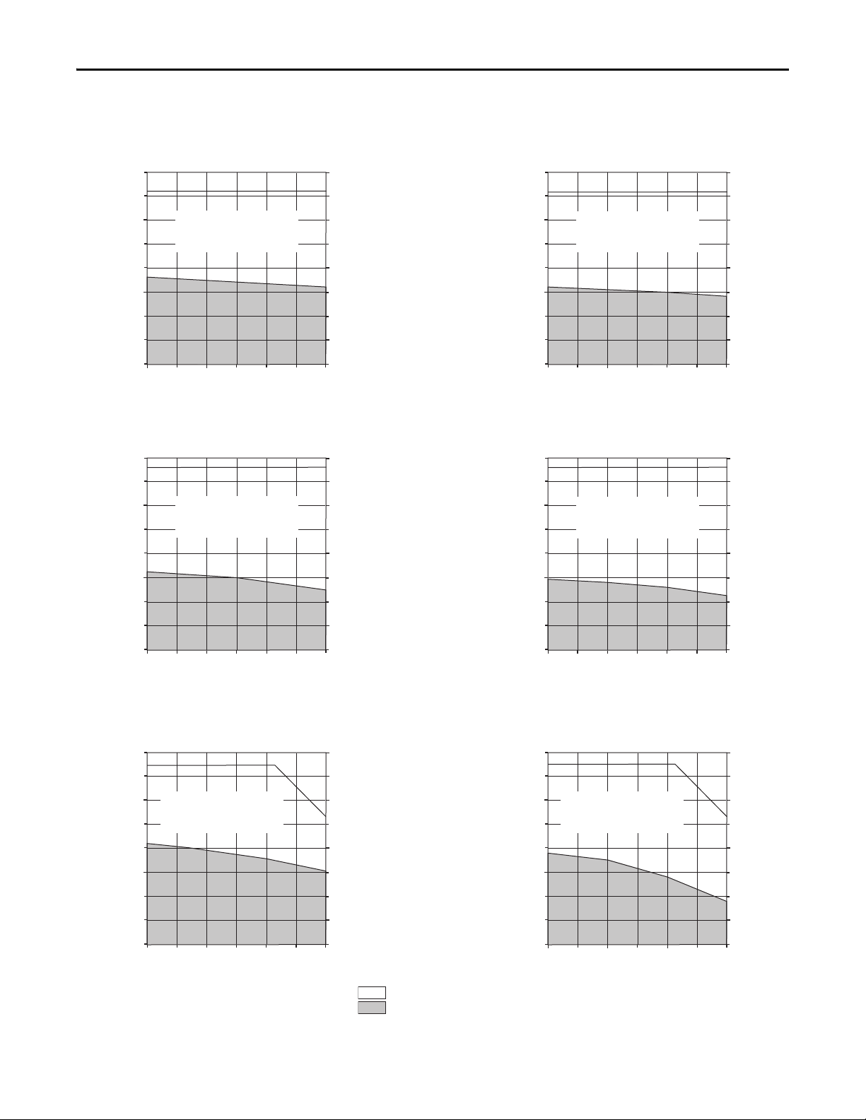
Kinetix 3 (200V-class) Drives/TL-Axxxx-B (absolute high-resolution) Motor Curves
Torque
(N•m)
Torque
(lb•in)
Speed (rpm)
2071-AP1 and TL-A120P-B
0
3000
5000
0.400
0.350
0.300
0.250
0.200
0.150
0.100
0.050
0
40001000
2000
Intermittent curve represents
single-phase input.
3.54
3.09
2.65
2.21
1.77
1.33
0.88
0.44
0
Torque
(N•m)
Torque
(lb•in)
Speed (rpm)
2071-AP1 and TL-A130P-B
0
3000
5000
0.800
0.700
0.600
0.500
0.400
0.300
0.200
0.100
0
40001000
2000
Intermittent curve represents
single-phase input.
7.07
6.19
5.31
4.42
3.54
2.65
1.77
0.88
0
Torque
(N•m)
Torque
(lb•in)
Speed (rpm)
2071-AP4 and TL-A220P-B
0
3000
5000
1.600
1.400
1.200
1.000
0.800
0.600
0.400
0.200
0
40001000
2000
14.1
12.4
10.6
8.84
7.07
5.31
3.54
1.77
0
Intermittent curve represents
single-phase input.
= Intermittent operating region
= Continuous operating region
2071-AP1 and TL-A120P-B (Brake)
0.400
Torque
(N•m)
0.350
0.300
Intermittent curve represents
single-phase input.
2071-AP1 and TL-A130P-B (Brake)
Intermittent curve represents
single-phase input.
2000
Torque
(N•m)
0.250
0.200
0.150
0.100
0.050
0
0
0.800
0.700
0.600
0.500
0.400
0.300
0.200
0.100
0
0
3000
2000
Speed (rpm)
3000
Speed (rpm)
Kinetix 3 Drive Systems
3.54
3.09
2.65
2.21
1.77
1.33
0.88
0.44
0
5000
40001000
7.07
6.19
5.31
4.42
3.54
2.65
1.77
0.88
0
5000
40001000
Torque
(lb•in)
Torque
(lb•in)
2071-AP4 and TL-A220P-B (Brake)
1.600
Torque
(N•m)
1.400
1.200
1.000
Intermittent curve represents
single-phase input.
0.800
Rockwell Automation Publication GMC-RM005B-EN-P - September 2013 15
0.600
0.400
0.200
0
0
2000
3000
40001000
Speed (rpm)
5000
14.1
12.4
10.6
8.84
7.07
5.31
3.54
1.77
0
Torque
(lb•in)
Page 16

Kinetix 3 Drive Systems
Torque
(N•m)
Torque
(lb•in)
Speed (rpm)
2071-AP4 and TL-A230P-B
0
3000
5000
4.00
3.50
3.00
2.50
2.00
1.50
1.00
0.50
0
40001000
2000
Intermittent curve represents
single-phase input.
35.4
30.9
26.5
22.1
17.7
13.3
8.84
4.42
0
Torque
(N•m)
Torque
(lb•in)
Speed (rpm)
2071-AP8 and TL-A2540P-B
0
3000
5000
8.00
7.00
6.00
5.00
4.00
3.00
2.00
1.00
0
40001000
2000
Intermittent curve represents
single-phase and three-phase inputs.
70.7
61.9
53.1
44.2
35.4
26.5
17.7
88.4
0
Torque
(N•m)
Torque
(lb•in)
Speed (rpm)
2071-A15 and TL-A410M-B
0
3000
5000
16.0
14.0
12.0
10.0
8.0
6.0
4.0
2.0
0
40001000
2000
141
124
106
88.4
70.7
35.4
26.5
17.7
0
Intermittent curve represents
three-phase input.
= Intermittent operating region
= Continuous operating region
Kinetix 3 (200V-class) Drives/TL-Axxxx-B (absolute high-resolution) Motor Curves (continued)
2071-AP4 and TL-A230P-B (Brake)
(N•m)
(N•m)
4.00
3.50
3.00
2.50
2.00
1.50
1.00
0.50
8.00
7.00
6.00
5.00
4.00
3.00
2.00
1.00
Intermittent curve represents
single-phase input.
0
0
2000
Speed (rpm)
2071-AP8 and TL-A2540P-B (Brake)
Intermittent curve represents
single-phase and three-phase input.
0
0
2000
Speed (rpm)
3000
3000
40001000
40001000
Torque
Torque
5000
5000
35.4
30.9
26.5
22.1
17.7
13.3
8.84
4.42
0
70.7
61.9
53.1
44.2
35.4
26.5
17.7
88.4
0
Torque
(lb•in)
Torque
(lb•in)
Torque
(N•m)
16 Rockwell Automation Publication GMC-RM005B-EN-P - September 2013
16.0
14.0
12.0
10.0
8.0
6.0
4.0
2.0
2071-A15 and TL-A410M-B (Brake)
Intermittent curve represents
three-phase input.
0
0
2000
Speed (rpm)
3000
141
Torque
(lb•in)
124
106
88.4
70.7
35.4
26.5
17.7
0
5000
40001000
Page 17

Kinetix 3 Drive Systems
Kinetix 3 (200V-class) Drives with LDAT-Series Integrated Linear Thrusters
This section provides system combination information for the Kinetix 3 (200V-class) drives when matched with
LDAT-Series integrated linear thrusters. Included are motor power and feedback cable catalog numbers, system
performance specifications, and force/velocity curves.
LDAT-Series Cable Combinations
LDAT-Series Linear Thrusters Motor Power Cable Motor Feedback Cable
(1)
LDAT-S031xxx-xBx, LDAT-S032xxx-xBx, LDAT-S033xxx-xBx
LDAT-S051xxx-xBx, LDAT-S052xxx-xBx, LDAT-S053xxx-xBx, LDAT-S054xxx-xBx
LDAT-S072xxx-xBx, LDAT-S073xxx-xBx, LDAT-S074xxx-xBx, LDAT-S076xxx-EBx
LDAT-S102xxx-xBx, LDAT-S103xxx-xBx, LDAT-S104xxx-xBx, LDAT-S106xxx-EBx
2090-CPWM7DF-16AAxx (standard, non-flex)
2090-CPWM7DF-16AFxx (continuous- flex)
2090-XXNFMF-Sxx (standard, non-flex)
2090-CFBM7DF-CDAFxx (continuous-fl ex)
Incremental Feedback
LDAT-S152xxx-xBx, LDAT-S153xxx-xBx, LDAT-S154xxx-xBx, LDAT-S156xxx-EBx
(1) Use 2071-TBMF breakout board on drive end (battery not required). Refer to Kinetix 3 Motor Feedback Example (Bulletin MPAS, LDAT-Series, LDC-Series, and LDL-S eries) on page4 for more inform ation.
For cable configuration illustrations and feature descriptions, by catalog number, refer to 2090-Series Motor/Actuator Cables Overview beginning on page 7.
Motor-end connector kits are available for motor power/brake and feedback cables. Refer to Optional Drive Accessories on page 6
Cable len gth xx is in meters. Refer to the Kinetix Motion Accessories Technical Data, publication GMC-TD004
, for standard cable lengths.
.
LDAT-Series Performance Specifications with Kinetix 3 (200V-class) Drives
Performance Specifications with Frame 30 Linear Thrusters
Linear Thruster
Cat. No.
LDAT-S031 010-DBx 2.4
LDAT-S031 020-DBx 3.1 0.25
LDAT-S031 030-DBx 3.5 0.29
LDAT-S031 040-DBx 3.8 0.31
LDAT-S032 010-DBx 3.1
LDAT-S032 020-DBx 4.1 0.52
LDAT-S032 030-DBx 4.7 0.59
LDAT-S032 040-DBx 5.0 0.63
LDAT-S032 010-EBx 3.1
LDAT-S032 020-EBx 4.1 0.47
LDAT-S032 030-EBx 4.7 0.52
LDAT-S032 040-EBx 5.0 0.55
LDAT-S033 010-DBx 3.5
LDAT-S033 020-DBx 4.7 0.88
LDAT-S033 030-DBx
LDAT-S033 040-DBx
LDAT-S033 010-EBx 3.5
LDAT-S033 020-EBx
LDAT-S033 040-EBx
Performance specification data and curves reflect nominal sys tem performance of a typical system with motor at 40 °C (104 °F) and drive at 50 °C (122 °F) ambient and rated line voltage. For additional
information on ambient and line conditions, refer to Motion Analyzer software.
Velocit y, max
230V AC
m/s
5.0 0.95
4.4 0.65LDAT-S033 030-EBx
System Continuous
Stall Current
Amps 0-pk
4.8 81 (18) 12.2 168 (38)
7.4
3.7 12.2
11.1
3.7 12.2
System Continuous
Stall Force
N (lb)
126 (28)
190 (43)
System Peak
Stall Current
Amps 0-pk
24.3
36.5
System Peak
Stall Force
N (lb)
336 (76)
504 (113)
Rated Output
230V AC
kW
0.20
0.44
0.40
0.67
0.55
Kinetix 3
200V-class Drives
2071-AP8
2071-A10
2071-AP8
2071-A15
-A
P8
2071
Rockwell Automation Publication GMC-RM005B-EN-P - September 2013 17
Page 18

Kinetix 3 Drive Systems
Performance Specifications with Frame 50 Linear Thruster
Linear Thruster
Cat. No.
LDAT-S051 010-DBx 2.8
LDAT-S051 020-DBx 3.7 0.38
LDAT-S051 030-DBx 4.1 0.42
LDAT-S051 040-DBx 4.4 0.44
LDAT-S051 050-DBx 4.7 0.46
LDAT-S052 010-DBx 3.7
LDAT-S052 020-DBx 4.8 0.97
LDAT-S052 030-DBx
LDAT-S052 050-DBx
LDAT-S052 010-EBx
…
LDAT-S052 050-EBx
LDAT-S053 010-DBx 4.1
LDAT-S053 020-DBx 5.0 1.53
LDAT-S053 030-DBx
…
LDAT-S053 050-DBx
LDAT-S053 010-EBx
…
LDAT-S053 050-EBx
LDAT-S054 010-DBx 4.4
LDAT-S054 020-DBx
…
LDAT-S054 050-DBx
LDAT-S054 010-EBx
…
LDAT-S054 050-EBx
Veloc ity, max
230V AC
m/s
5.00 1.01LDAT-S052 040-DBx
2.6 3.1 11.4 0.50 2071-AP4
5.0 1.53
1.7 3.1 11.4 0.47 2071-AP4
5.0 2.05
2.6 6.2 22.7 1.02 2071-AP8
System Continuous
Stall Current
Amps 0-pk
3.1 119 (27) 11.4 363 (82)
6.2
9.4
12.4
System Continuous
Stall Force
N (lb)
251 (56)
378 (85)
509 (114)
System Peak
Stall Current
Amps 0-pk
22.7
34.2
45.5
System Peak
Stall Force
N (lb)
727 (163)
1093 (246)
1453 (327)
Rated Output
230V AC
kW
0.31
0.79
1.31
1.8
Kinetix 3
200V-class Drives
2071-AP4
2071-AP8
2071-A10
7
A15
2071-
Performance specification data and curves reflect nominal sys tem performance of a typical system with motor at 40 °C (104 °F) and drive at 50 °C (122 °F) ambient and rated line voltage. For additional
information on ambient and line conditions, refer to Motion Analyzer software.
18 Rockwell Automation Publication GMC-RM005B-EN-P - September 2013
Page 19

Performance Specifications with Frame 70 Linear Thrusters
Kinetix 3 Drive Systems
Linear Thruster
Cat. No.
LDAT-S072 010-DBx
…
LDAT-S072 070-DBx
LDAT-S072 010-EBx
…
LDAT-S072 070-EBx
LDAT-S073 010-DBx
…
LDAT-S073 070-DBx
LDAT-S073 010-EBx
…
LDAT-S073 070-EBx
LDAT-S074 010-DBx
…
LDAT-S074 070-DBx
LDAT-S074 010-EBx
…
LDAT-S074 070-EBx
LDAT-S076 010-EBx
…
LDAT-S076 070-EBx
Performance specification data and curves reflect nominal sys tem performance of a typical system with motor at 40 °C (104 °F) and drive at 50 °C (122 °F) ambient and rated line voltage. For additional
information on ambient and line conditions, refer to Motion Analyzer software.
Veloc ity, max
230V AC
m/s
3.5 6.0
1.7 3.0 11.0 0.47 2071-AP4
3.5 9.0
1.2 3.0 10.9 0.41 2071-AP4
3.5 11.9
1.8 6.0 21.7 0.95 2071-AP8
1.8 9.1 1122 (252) 33.2 3 189 (717) 1.45 2071-A10
System Continuous
Stall Current
Amps 0-pk
System Continuous
Stall Force
N (lb)
364 (82)
554 (125)
730 (164)
System Peak
Stall Current
Amps 0-pk
22.0
32.8
43.5
System Peak
Stall Force
N (lb)
1055 (237)
1576 (354)
2088 (469)
Rated Output
230V AC
kW
1.03 2071-AP8
1.57 2071-A10
2.08 2071-A15
Kinetix 3
200V-class Drives
Performance Specifications with Frame 100 Linear Thrusters
Linear Thruster
Cat. No.
LDAT-S102 010-DBx
…
AT
-S102090-DBx
LD
LDAT-S102 010-EBx
…
LDAT-S102 090-EBx
LDAT-S103 010-DBx
…
LDAT-S103 090-DBx
LDAT-S103 010-EBx
…
LDAT-S103 090-EBx
LDAT-S104 010-DBx
…
LDAT-S104 090-DBx
LDAT-S104 010-EBx
…
LDAT-S104 090-EBx
LDAT-S106 010-EBx
…
LDAT-S106 090-EBx
Performance specification data and curves reflect nominal sys tem performance of a typical system with motor at 40 °C (104 °F) and drive at 50 °C (122 °F) ambient and rated line voltage. For additional
information on ambient and line conditions, refer to Motion Analyzer software.
Veloc ity, max
230V AC
m/s
2.6 5.7
1.3 2.9 10.5 0.42 2071-AP4
2.7 8.6
0.9 2.9 10.5 1388 (312) 0.30 2071-AP4
2.7 11.5
1.3 5.7 21.0 0.86 2071-AP8
1.3 8.6 1403 (315) 31.5 3871 (870) 1.28 2071-A10
System Continuous
Stall Current
Amps 0-pk
System Continuous
Stall Force
N (lb)
456 (103)
702 (158)
929 (209)
System Peak
Stall Current
Amps 0-pk
21.0
31.5 1935 (435) 1.47 2071-A10
42.0
System Peak
Stall Force
N (lb)
1289 (290)
2578 (580)
Rated Output
230V AC
kW
0.96 2071-AP8
2.07 2071-A15
Kinetix 3
200V-class Drives
Rockwell Automation Publication GMC-RM005B-EN-P - September 2013 19
Page 20

Kinetix 3 Drive Systems
2071-AP8 and LDAT-S031040-DBx
Velocity (m/s)
Force
(N)
Force
(lb)
200
175
150
125
100
75
50
25
0
45.0
39.3
33.7
28.1
22.5
16.9
11.2
5.6
0
0
2
4
31
= Intermittent operating region
= Continuous operating region
Performance Specifications with Frame 150 Linear Thrusters
Linear Thruster
Cat. No.
LDAT-S152 010-DBx
…
LDAT-S152 090-DBx
LDAT-S152 010-EBx
…
LDAT-S152 090-EBx
LDAT-S153 010-DBx
…
LDAT-S153 090-DBx
LDAT-S153 010-EBx
…
LDAT-S153 090-EBx
LDAT-S154 010-DBx
…
LDAT-S154 090-DBx
LDAT-S154 010-EBx
…
LDAT-S154 090-EBx
LDAT-S156 010-EBx
…
LDAT-S156 090-EBx
Performance specification data and curves reflect nominal sys tem performance of a typical system with motor at 40 °C (104 °F) and drive at 50 °C (122 °F) ambient and rated line voltage. For additional
information on ambient and line conditions, refer to Motion Analyzer software.
Veloc ity, max
230V AC
m/s
1.8 5.3
0.9 2.7 9.8 1679 (377) 0.34 2071-AP4
1.8 8.0 978 (220) 29.1 2680 (602) 1.33 2071-A10
1.8 10.7
0.9 5.3 19.5 3383 (761) 0.70 2071-A15
1.8 16.3
0.9 8.1 19.8 5110 (1149) 1.05 2071-A10
System Continuous
Stall Current
Amps 0-pk
System Continuous
Stall Force
N (lb)
643 (145)
1306 (294)
1997 (449)
System Peak
Stall Current
Amps 0-pk
19.5 1799 (404) 0.87 2071-AP8
39.1 3597 (809) 1.78 2071-AP4
59.4 5469 (1229) 2.71 2071-AP8
System Peak
Stall Force
N (lb)
Rated Output
230V AC
kW
Kinetix 3
200V-class Drives
Kinetix 3 (200V-class) Drives/LDAT-Series Integrated Linear Thruster Curves
20 Rockwell Automation Publication GMC-RM005B-EN-P - September 2013
Page 21

Kinetix 3 (200V-class) Drives/LDAT-Series Integrated Linear Thruster Curves (continued)
Velocity (m/s)
0
3
5
41
2
Force
(N)
Force
(lb)
400
350
300
250
200
150
100
50
0
89.9
78.7
67.4
56.2
45.0
33.7
22.5
11.2
0
2071-A10 and LDAT-S032040-DBx
Velocity (m/s)
0
3
5
41
2
Force
(N)
Force
(lb)
400
350
300
250
200
150
100
50
0
89.9
78.7
67.4
56.2
45.0
33.7
22.5
11.2
0
2071-AP8 and LDAT-S032040-EBx
2071-A15 and LDAT-S033040-DBx
Velocity (m/s)
Force
(N)
Force
(lb)
600
525
450
375
300
225
150
75
0
135
118
101
84.3
67.4
50.6
33.7
16.9
0
0
3
5
41
2
Velocity (m/s)
Force
(N)
Force
(lb)
600
525
450
375
300
225
150
75
0
135
118
101
84.3
67.4
50.6
33.7
16.9
0
0
3
5
41
2
2071-AP8 and LDAT-S033040-EBx
Velocity (m/s)
0
3
5
41
2
Force
(N)
Force
(lb)
400
350
300
250
200
150
100
50
0
89.9
78.7
67.4
56.2
45.0
33.7
22.5
11.2
0
2071-AP4 and LDAT-S051050-DBx
= Intermittent operating region
= Continuous operating region
Kinetix 3 Drive Systems
Rockwell Automation Publication GMC-RM005B-EN-P - September 2013 21
Page 22

Kinetix 3 Drive Systems
Velocity (m/s)
0
3
5
41
2
Force
(N)
Force
(lb)
800
700
600
500
400
300
200
100
0
180
157
135
112
90.0
67.4
45.0
22.5
0
2071-AP8 and LDAT-S052050-DBx
Velocity (m/s)
Force
(N)
Force
(lb)
0
1.5
2.5
2.00.5
1.0
3.0
800
700
600
500
400
300
200
100
0
180
157
135
112
90.0
67.4
45.0
22.5
0
2071-AP4 and LDAT-S052050-EBx
Velocity (m/s)
Force
(N)
Force
(lb)
1200
1050
900
750
600
450
300
150
0
270
236
202
169
135
101
67.4
33.7
0
0
3
5
41
2
2071-A10 and LDAT-S053050-DBx
Velocity (m/s)
Force
(N)
Force
(lb)
0
1.5
2.5
2.00.5
1.0
3.0
1200
1050
900
750
600
450
300
150
0
270
236
202
169
135
101
67.4
33.7
0
2071-AP4 and LDAT-S053050-EBx
2071-A15 and LDAT-S054050-DBx
Velocity (m/s)
Force
(N)
Force
(lb)
0
3
5
41
2
1500
1200
900
600
300
0
337
270
202
135
67.4
0
2071-AP8 and LDAT-S054050-EBx
Force
(N)
Force
(lb)
1500
1200
900
600
300
0
337
270
202
135
67.4
0
Velocity (m/s)
0
1.5
2.5
2.00.5
1.0
3.0
= Intermittent operating region
= Continuous operating region
Kinetix 3 (200V-class) Drives/LDAT-Series Integrated Linear Thruster Curves (continued)
22 Rockwell Automation Publication GMC-RM005B-EN-P - September 2013
Page 23

Kinetix 3 (200V-class) Drives/LDAT-Series Integrated Linear Thruster Curves (continued)
2071-AP8 and LDAT-S072070-DBx
Force
(N)
Force
(lb)
1200
1050
900
750
600
450
300
150
0
270
236
202
169
135
101
67.4
33.7
0
Velocity (m/s)
0
2
4
31
2071-AP4 and LDAT-S072070-EBx
Force
(N)
Force
(lb)
1200
1050
900
750
600
450
300
150
0
270
236
202
169
135
101
67.4
33.7
0
Velocity (m/s)
0
1.0
2.0
1.50.5
2071-A10 and LDAT-S073070-DBx
Velocity (m/s)
Force
(N)
Force
(lb)
1600
1400
1200
1000
800
600
400
200
0
360
315
270
225
180
135
89.9
45.0
0
0
2.0
4.0
3.01.0
2071-AP4 and LDAT-S073070-EBx
Velocity (m/s)
Force
(N)
Force
(lb)
1600
1400
1200
1000
800
600
400
200
0
360
315
270
225
180
135
89.9
45.0
0
0
1.0
2.0
1.50.5
2071-A15 and LDAT-S074070-DBx
Velocity (m/s)
Force
(N)
Force
(lb)
2400
2100
1800
1500
1200
900
600
300
0
540
472
405
337
270
202
135
67.4
0
0
2.0
4.0
3.01.0
2071-AP8 and LDAT-S074070-EBx
Velocity (m/s)
Force
(N)
Force
(lb)
2400
2100
1800
1500
1200
900
600
300
0
540
472
405
337
270
202
135
67.4
0
0
1.0
2.0
1.50.5
= Intermittent operating region
= Continuous operating region
Kinetix 3 Drive Systems
Rockwell Automation Publication GMC-RM005B-EN-P - September 2013 23
Page 24

Kinetix 3 Drive Systems
2071-A10 and LDAT-S076070-EBx
Velocity (m/s)
Force
(N)
Force
(lb)
3200
2800
2400
2000
1600
1200
800
400
0
719
629
540
450
360
270
180
89.9
0
0
1.0
2.0
1.50.5
2071-AP8 and LDAT-S102090-DBx
Force
(N)
Force
(lb)
1500
1200
900
600
300
0
337
270
202
135
67.4
0
Velocity (m/s)
0
1.5
2.5
2.00.5
1.0
3.0
2071-AP4 and LDAT-S102090-EBx
Force
(N)
Force
(lb)
1500
1200
900
600
300
0
337
270
202
135
67.4
0
Velocity (m/s)
0
1.0
2.0
1.50.5
2071-A10 and LDAT-S103090-DBx
Force
(N)
Force
(lb)
2000
1750
1500
1250
1000
750
500
250
0
450
393
337
281
225
169
112
56.2
0
Velocity (m/s)
0
1.5
2.5
2.00.5
1.0
3.0
2071-AP4 and LDAT-S103090-EBx
Force
(N)
Force
(lb)
1500
1200
900
600
300
0
337
270
202
135
67.4
0
Velocity (m/s)
0
0.5
1.0
0.750.25
= Intermittent operating region
= Continuous operating region
Kinetix 3 (200V-class) Drives/LDAT-Series Integrated Linear Thruster Curves (continued)
24 Rockwell Automation Publication GMC-RM005B-EN-P - September 2013
Page 25

Kinetix 3 (200V-class) Drives/LDAT-Series Integrated Linear Thruster Curves (continued)
Velocity (m/s)
89.9
180
270
360
450
540
0
400
800
1200
1600
2000
2400
2800
629
0
Force
(N)
Force
(lb)
0
1.5
2.5
2.00.5
1.0
3.0
2071-A15 and LDAT-S104090-DBx
89.9
180
270
360
450
540
0
400
800
1200
1600
2000
2400
2800
629
0
Force
(N)
Force
(lb)
2071-AP8 and LDAT-S104090-EBx
Velocity (m/s)
0
1.0
2.0
1.50.5
2071-A10 and LDAT-S106090-EBx
Force
(N)
Force
(lb)
4000
3500
3000
2500
2000
1500
1000
500
0
899
787
674
562
450
337
225
112
0
Velocity (m/s)
0
1.0
2.0
1.50.5
2071-AP8 and LDAT-S152090-DBx
Force
(N)
Force
(lb)
Velocity (m/s)
0
1.0
2.0
1.50.5
2000
1750
1500
1250
1000
750
500
250
0
450
393
337
281
225
169
112
56.2
0
2071-AP4 and LDAT-S152090-EBx
Force
(N)
Force
(lb)
Velocity (m/s)
0
1.50
1.0
1.750.25
2000
1750
1500
1250
1000
750
500
250
0
450
393
337
281
225
169
112
56.2
0
= Intermittent operating region
= Continuous operating region
Kinetix 3 Drive Systems
Rockwell Automation Publication GMC-RM005B-EN-P - September 2013 25
Page 26

Kinetix 3 Drive Systems
89.9
180
270
360
450
540
0
400
800
1200
1600
2000
2400
2800
629
0
Force
(N)
Force
(lb)
2071-A10 and LDAT-S153090-DBx
Velocity (m/s)
0
1.0
2.0
1.50.5
2071-A15 and LDAT-S154090-DBx
Force
(N)
Force
(lb)
4000
3500
3000
2500
2000
1500
1000
500
0
899
787
674
562
450
337
225
112
0
Velocity (m/s)
0
1.0
2.0
1.50.5
2071-AP8 and LDAT-S154090-EBx
Force
(N)
Force
(lb)
4000
3500
3000
2500
2000
1500
1000
500
0
899
787
674
562
450
337
225
112
0
Velocity (m/s)
0
1.50
1.0
1.750.25
180
360
540
719
899
1079
0
800
1600
2400
3200
4000
4800
5600
1259
0
Force
(N)
Force
(lb)
2071-A10 and LDAT-S156090-EBx
Velocity (m/s)
0
1.50
1.0
1.750.25
= Intermittent operating region
= Continuous operating region
Kinetix 3 (200V-class) Drives/LDAT-Series Integrated Linear Thruster Curves (continued)
26 Rockwell Automation Publication GMC-RM005B-EN-P - September 2013
Page 27

Kinetix 3 Drive Systems
Kinetix 3 (200V-class) Drives with MP-Series Integrated Linear Stages
This section provides system combination information for the Kinetix 3 (200V-class) drives when matched with
MP-Series™ (200V-class) integrated direct-drive linear stages. Included are motor power and feedback cable catalog
numbers, system performance specifications, and force/velocity curves.
Bulletin MPAS Cable Combinations
Linear Stage Motor Power/Brake Cable Motor Feedback Cable
MPAS-A6xxxB-ALMx2C,
MPAS-A8xxxE-ALMx2C,
MPAS-A9xxxK-ALM x2C
(1) Use 2071-TBMF breakout board on drive end (battery not required). Refer to Kinetix 3 Motor Feedback Example (Bulletin MPAS, LDAT-Series, LDC-Series™, and LDL-S eries™) on page 4 for more
information.
For cable configuration illustrations and feature descriptions, by catalog number, refer to 2090-Series Motor/Actuator Cables Overview beginning on page 7.
Motor-end connector kits are available for motor power/brake and feedback cables. Refer to Optional Drive Accessories on page 6
Cable len gth xx is in meters. Refer to the Kinetix Motion Accessories Technical Data, publication GMC-TD004
2090-CPxM7DF-16AAxx (standard) or
2090-CPxM7DF-16AFxx (continuous-flex)
.
, for standard cable lengths.
2090-XXNFMF-Sxx (standard, non-flex)
2090-CFBM7DF-CDAFxx (continuous-flex)
Incremental Feedback
(1)
Bulletin MPAS Performance Specifications with Kinetix 3 (200V-class) Drives
Linear Stage
MPAS-A6xxxB-ALMO2C
MPAS-A6xxxB-ALMS2C 4.7 83.0 (18.7) 14.2 312 (70.1) 0.29
MPAS-A8xxxE-ALMO2C 7.0 189 (42.5) 18.5 456 (103) 0.53
MPAS-A8xxxE-ALMS2C 6.3 159 (35.7) 16.7 399 (89.7) 0.48
MPAS-A9xxxK-ALMO2C 6.7 285 (64.1) 18.3 680 (153) 0.77
MPAS-A9xxxK-ALMS2C 6.1 245 (55.1) 16.5 601 (135) 0.69
Performance specification data and curves reflect nominal sys tem performance of a typical system with actuator at 40 °C (104 °F) and drive at 50 °C (122 °F) ambient and rated line voltage. For additional
information on ambient and line conditions, refer to Motion Analyzer software.
Speed, max
mm/s (in/s)
5000 (200)
System Continuous
Stall Current
Amps 0-pk
5.3 105 (23.6) 15.8 359 (80.7) 0.32
System Continuous
Stall Force
N (lb)
System Peak
Stall Current
Amps 0-pk
System Peak
Stall Force
N (lb)
Linear Stage
Rated Output
kW
Kinetix 3
200V-class Drives
2071-AP8
Rockwell Automation Publication GMC-RM005B-EN-P - September 2013 27
Page 28

Kinetix 3 Drive Systems
Velocity (mm/s)
0
3000
5000
40001000
2000
Force
(N)
Force
(lb)
2071-AP8 and MPAS-A6xxxB-ALMO2C
400
350
300
250
200
150
100
50
0
89.9
78.7
67.4
56.2
45.0
33.7
22.5
11.2
0
Velocity (mm/s)
0
3000
5000
40001000
2000
Force
(N)
Force
(lb)
2071-AP8 and MPAS-A6xxxB-ALMS2C
400
350
300
250
200
150
100
50
0
89.9
78.7
67.4
56.2
45.0
33.7
22.5
11.2
0
Velocity (mm/s)
0
3000
5000
40001000
2000
Force
(N)
Force
(lb)
2071-AP8 and MPAS-A8xxxE-ALMO2C
800
700
600
500
400
300
200
100
0
179.8
157.4
134.9
112.4
89.9
67.4
45.0
22.5
0
Velocity (mm/s)
0
3000
5000
40001000
2000
Force
(N)
Force
(lb)
2071-AP8 and MPAS-A8xxxE-ALMS2C
800
700
600
500
400
300
200
100
0
179.8
157.4
134.9
112.4
89.9
67.4
45.0
22.5
0
Velocity (mm/s)
0
3000
5000
40001000
2000
Force
(N)
Force
(lb)
2071-AP8 and MPAS-A9xxxK-ALMO2C
800
700
600
500
400
300
200
100
0
179.8
157.4
134.9
112.4
89.9
67.4
45.0
22.5
0
Velocity (mm/s)
0
3000
5000
40001000
2000
Force
(N)
Force
(lb)
2071-AP8 and MPAS-A9xxxK-ALMS2C
800
700
600
500
400
300
200
100
0
179.8
157.4
134.9
112.4
89.9
67.4
45.0
22.5
0
= Intermittent operating region
= Continuous operating region
= System operation for specified stroke length
Kinetix 3 (200V-class) Drives/MP-Series Integrated Linear Stage Curves
28 Rockwell Automation Publication GMC-RM005B-EN-P - September 2013
Page 29

Kinetix 3 Drive Systems
Kinetix 3 (200V-class) Drives with TL-Series Electric Cylinders
This section provides system combination information for the Kinetix 3 drives when matched with TL-Series (200V-class)
electric cylinders. Included are power/brake and feedback cable catalog numbers, system performance specifications, and
the optimum force/velocity curves.
Bulletin TLAR Cable Combinations
Electric Cylinder Motor Power/Brake Cable Motor Feedback Cable
TLAR-A1xxxB
TLAR-A1xxxE
TLAR-A2xxxC
TLAR-A2xxxF
TLAR-A3xxxE
TLAR-A3xxxH
(1) The TLY-Axxxx-B motors with 17-bit high-resolution encoder feedback (mounted to the electric cylinder) require 2090-CFBM6DF-CBAAxx flying-lead feedback cables and 2071-TBMF connector kit (with
customer-supplied battery). Refer to Kinetix 3 Moto r Feedback Example (Bulletin TLY rotary motors or TLAR electric cylinders) on page 4
For cable configuration illustrations and feature descriptions, by catalog number, refer to 2090-Series Motor/Actuator Cables Overview beginning on page 7.
Motor-end connector kits are available for motor power/brake and feedback cables. Refer to Optional Drive Accessories on page 6
Cable len gth xx is in meters. Refer to the Kinetix Motion Accessories Technical Data, publication GMC-TD004
2090-CPWM6DF-16AAxx (standard, non-flex)
(without brake)
2090-CPBM6DF-16AAxx (standard, non-flex)
(with brake)
.
, for standard cable lengths.
2090-CFBM6DF-CBAAxx (standard, non-flex)
Absolute High-resolution Feedback
for more information.
(1)
Bulletin TLAR (non-brake) Performance Specifications with Kinetix 3 Drives
Electric Cylinder
TLAR-A1xxxB 150 1.36 240 (53.9) 1.79 300 (67.4) 0.036 2071-AP0
TLAR-A1xxxE 500 2.59 280 (62.9) 3.03 350 (78.7) 0.140 2071-AP2
TLAR-A2xxxC 250 3.03 420 (94.4) 3.41 525 (118) 0.105 2071-AP2
TLAR-A2xxxF 640 5.50 640 (144) 7.25 800 (180) 0.350 2071-AP4
TLAR-A3xxxE500
TLAR-A3xxxH 1000 1300 (292) 17.2 1625 (365) 2071-A15
Speed, max
mm/s (in/s)
System Continuous
Stall Current
Amps 0-pk
10.0
System Continuous
Stall Force
N (lb)
2000 (450) 12.9 2500 (562)
System Peak
Stall Current
Amps 0-pk
System Peak
Stall Force
N (lb)
Rated OutputkWKinetix 3
0.930
200V-class Drives
2071-A10
Bulletin TLAR (brake) Performance Specifications with Kinetix 3 Drives
Electric Cylinder
TLAR-A1xxxB 150 1.18 240 (53.9) 1.79 300 (67.4) 0.036 2071-AP0
TLAR-A1xxxE 500 2.24 280 (62.9) 3.03 350 (78.7) 0.140 2071-AP2
TLAR-A2xxxC 250 2.68 420 (94.4) 3.41 525 (118) 0.105 2071-AP2
TLAR-A2xxxF 640 4.95 640 (144) 7.25 800 (180) 0.350 2071-AP4
TLAR-A3xxxE500
TLAR-A3xxxH
Performance specification data and curves reflect nominal sys tem performance of a typical system with actuator at 40 °C (104 °F) and drive at 50 °C (122 °F) ambient and rated line voltage. For additional
information on ambient and line conditions, refer to Motion Analyzer software.
Speed, max
mm/s (in/s)
1000 1300 (292) 17.2 1625 (365) 2071-A15
System Continuous
Stall Current
Amps 0-pk
10.0
Rockwell Automation Publication GMC-RM005B-EN-P - September 2013 29
System Continuous
Stall Force
N (lb)
2000 (450) 12.9 2500 (562)
System Peak
Stall Current
Amps 0-pk
System Peak
Stall Force
N (lb)
Rated OutputkWKinetix 3
200V-class Drives
2071-A10
0.930
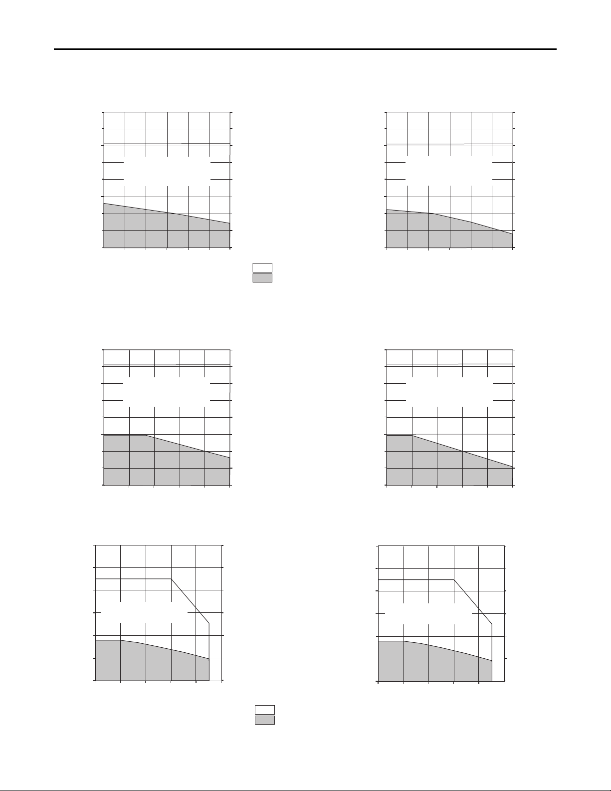
Page 30

Kinetix 3 Drive Systems
500
400
300
200
100
0
112
89.9
67.4
45.0
22.5
0
Velocity (mm/s)
150100
0
200
50
2071-AP0 and TLAR-A1xxxB-B2A
Force
(N)
Force
(lb)
500
400
300
200
100
0
112
89.9
67.4
45.0
22.5
0
Velocity (mm/s)
150100
0
200
50
2071-AP0 and TLAR-A1xxxB-B4A (Brake)
Force
(N)
Force
(lb)
500
400
300
200
100
0
112
89.9
67.4
45.0
22.5
0
2071-AP2 and TLAR-A1xxxE-B2A
Force
(N)
Force
(lb)
Velocity (mm/s)
100
400300
0
600
500
200
500
400
300
200
100
0
112
89.9
67.4
45.0
22.5
0
2071-AP2 and TLAR-A1xxxE-B4A (Brake)
Force
(N)
Force
(lb)
Velocity (mm/s)
100
400300
0
600
500
200
2071-AP2 and TLAR-A2xxxC-B2A
Force
(N)
Force
(lb)
Velocity (mm/s)
50
200150
0
300
250
100
22.5
45.0
67.4
89.9
112
135
0
100
200
300
400
500
600
700
157
0
2071-AP2 and TLAR-A2xxxC-B4A (Brake)
Force
(N)
Force
(lb)
Velocity (mm/s)
50
200150
0
300
250
100
22.5
45.0
67.4
89.9
112
135
0
100
200
300
400
500
600
700
157
0
= Intermittent operat ing region
= Continuous operating region
Kinetix 3 (200V-class) Drives/TL-Series Electric Cylinder Curves
30 Rockwell Automation Publication GMC-RM005B-EN-P - September 2013
Page 31

Kinetix 3 (200V-class) Drives/TL-Series Electric Cylinder Curves (continued)
1000
800
600
400
200
0
Velocity (mm/s)
6004000
800
200
2071-AP4 and TLAR-A2xxxF-B2A
Force
(N)
Force
(lb)
225
180
135
89.9
45.0
0
500300
700
100
1000
800
600
400
200
0
Velocity (mm/s)
6004000
800
200
2071-AP4 and TLAR-A2xxxF-B4A (Brake)
Force
(N)
Force
(lb)
225
180
135
89.9
45.0
0
500300
700
100
2071-A10 and TLAR-A3xxxE-B2A
Force
(N)
Force
(lb)
Velocity (mm/s)
100
400300
0
600
500
200
3000
2400
1800
1200
600
0
674
540
405
270
135
0
2071-A10 and TLAR-A3xxxE-B4A (Brake)
Force
(N)
Force
(lb)
Velocity (mm/s)
100
400300
0
600
500
200
3000
2400
1800
1200
600
0
674
540
405
270
135
0
2000
1600
1200
800
400
0
450
360
270
180
89.9
0
2071-A15 and TLAR-A3xxxH-B2A
Force
(N)
Force
(lb)
Velocity (mm/s)
200
800600
0
1200
1000
400
2000
1600
1200
800
400
0
450
360
270
180
89.9
0
2071-A15 and TLAR-A3xxxH-B4A (Brake)
Force
(N)
Force
(lb)
Velocity (mm/s)
200
800600
0
1200
1000
400
= Intermittent operating region
= Continuous operating region
Kinetix 3 Drive Systems
Rockwell Automation Publication GMC-RM005B-EN-P - September 2013 31
Page 32

Kinetix 3 Drive Systems
Kinetix 3 (200V-class) Drives with LDC-Series Linear Motors
This section provides system combination information for the Kinetix 3 drives when matched with LDC-Series iron-core
linear motors. Included are power and feedback cable catalog numbers, system performance specifications, and the
optimum force/velocity curves.
LDC-Series Cable Combinations
Linear Motor Motor Power Cable Motor Feedback Cable
LDC-C030100-DHT, LDC-C030200-DHT, LDC-C030200-EHT
LDC-C050100-DHT, LDC-C050200-DHT, LDC-C050200-EHT,
LDC-C050300-DHT, LDC-C050300-EHT
LDC-C075200-DHT, LDC-C075200-EHT,
LDC-C075300-DHT, LDC-C075300-EHT,
LDC-C075400-DHT, LDC-C075400-EHT
LDC-C100300-DHT, LDC-C100300-EHT,
LDC-C100400-DHT, LDC-C100400-EHT, LDC-C100600-DHT
LDC-C150400-DHT, LDC-C150600-DHT
(1) Use 2071-TBMF breakout board on drive end (battery not required). Refer to Kinetix 3 Motor Feedback Example (Bulletin MPAS, LDAT-Series, LDC-Series, and LDL-S eries) on page4 for more inform ation.
For cable configuration illustrations and feature descriptions, by catalog number, refer to 2090-Series Motor/Actuator Cables Overview beginning on page 7.
Motor-end connector kits are available for motor power/brake and feedback cables. Refer to Optional Drive Accessories on page 6
Cable len gth xx is in meters. Refer to the Kinetix Motion Accessories Technical Data, publication GMC-TD004
2090-CPWM7DF-16AAxx (standard, non-flex)
2090-CPWM7DF-16AFxx (continuous-flex)
.
, for standard cable lengths.
2090-XXNFMF-Sxx (standard, non-flex)
2090-CFBM7DF-CDAFxx (continuous-flex)
Sin/Cos or TTL Encoder Feedback
(1)
LDC-Series Performance Specifications with Kinetix 3 (200V-class) Drives
Linear Motor
LDC-C030100-DHT
LDC-C030200-DHT 8.1…12.2
LDC-C030200-EHT 4.1…6.1 12.1 2071-AP4
LDC-C050100-DHT
LDC-C050200-DHT 7.9…11.8
LDC-C050200-EHT 3.9…5.9 11.6 2071-AP4
LDC-C050300-DHT 11.8…17.7
LDC-C050300-EHT 3.9…5.9 12.0 2071-AP4
Speed, max
m/s (ft/s)
10.0 (32.8)
10.0 (32.8)
System Continuous
Stall Current
Amps 0-pk
4.1…6.1 74…111 (17…25) 12.1 188 (42) 0.37…0.55 2071-AP4
3.9…5.9 119…179 (27…40) 11.7 302 (68) 0.59…0.89 2071-AP4
(1)
System Continuous
Stall Force
N (lb)
148…222 (33…50)
240…359 (54…81)
363…544
(82…122)
(1)
System Peak
Stall Current
Amps 0-pk
24.3
23.3
35.9
System Peak
Stall Force
N (lb)
375 (84) 0.74…1.11
600 (135) 1.20…1.79
941 (212) 1.81…2.72
Linear Motor
Rated Output
kW
Kinetix 3
200V-class Drives
2071-A10
2071-A10
2071-A15
(1) Values represent the range between no cooling (low value) and water cooling (high value).
Performance specification data and curves reflect nominal sys tem performance of a typical system with actuator at 40 °C (104 °F) and drive at 50 °C (122 °F) ambient and rated line voltage. For additional
information on ambient and line conditions, refer to Motion Analyzer software.
32 Rockwell Automation Publication GMC-RM005B-EN-P - September 2013
Page 33

LDC-Series Performance Specifications with Kinetix 3 (200V-class) Drives (continued)
200
160
120
80
40
0
45.0
36.0
27.0
18.0
9.0
0
2071-AP4 and LDC-C030100-DHT
Force
(N)
Force
(lb)
Velocity (m/s)
2
86
0
12
10
4
Water Cooling
Air Cooling
No Cooling
400
320
240
160
80
0
89.9
71.9
53.9
36.0
18.0
0
2071-A10 and LDC-C030200-DHT
2071-AP4 and LDC-C030200-EHT
Force
(N)
Force
(lb)
Velocity (m/s)
2
86
0
12
10
4
Water Cooling
Air Cooling
No Cooling
= Intermittent operating region (LDC-Cxxxxxx-DHT)
= Intermittent operating region (LDC-Cxxxxxx-EHT)
= Continuous operating region
Kinetix 3 Drive Systems
Linear Motor
LDC-C075200-DHT
Speed, max
m/s (ft/s)
System Continuous
Stall Current
Amps 0-pk
7.7…11.5
LDC-C075200-EHT 3.8…5.7 11.5 2071-AP4
LDC-C075300-DHT 11.5…17.2
LDC-C075300-EHT 3.8…5.7 11.9 2071-AP4
10.0 (32.8)
LDC-C075400-DHT 15.3…23.0
LDC-C075400-EHT 7.7…11.5 23.7 2071-A10
LDC-C100300-DHT
11.1…16.7
LDC-C100300-EHT 3.7…5.6 11.4 2071-AP4
LDC-C100400-DHT 14.8…22.2
10.0 (32.8)
LDC-C100400-EHT 7.4…11.1 22.8 2071-A10
LDC-C100600-DHT 22.2…33.3
LDC-C150400-DHT
LDC-C150400-EHT 2071-A15
10.0 (32.8)
14.1…21.1
LDC-C150600-DHT 21.1…31.7
(1) Values represent the range between no cooling (low value) and water cooling (high value).
Performance specification data and curves reflect nominal sys tem performance of a typical system with actuator at 40 °C (104 °F) and drive at 50 °C (122 °F) ambient and rated line voltage. For additional
information on ambient and line conditions, refer to Motion Analyzer software.
(1)
System Continuous
Stall Force
(1)
N (lb)
348…523
(78…117)
523…784
(117…176)
697…1045
(157…235)
674…1012
(152…227)
899…1349
(202…303)
1349…2023
(303…455)
1281…1922
(288…432)
1922…2882
(432…648)
System Peak
Stall Current
Amps 0-pk
22.9
35.6
System Peak
Stall Force
N (lb)
Linear Motor
Rated Output
kW
882 (198) 1.74…2.61
Kinetix 3
200V-class Drives
2071-A10
2071-A15
1368 (308) 2.61…3.92
47.4
34.3
45.7
1824 (410) 3.48…5.22
1767 (397) 3.37…5.06
2071-A15
2071-A15
2071-A15
2356 (530) 4.49…6.74
68.5 3534 (794) 6.74…10.11 2071-A15
45.2 3498 (786) 6.40…9.61
2071-A10
67.8 5246 (1179) 9.61…14.41 2071-A15
Kinetix 3 (200V-class) Drives/LDC-Series Linear Motor Curves
Rockwell Automation Publication GMC-RM005B-EN-P - September 2013 33
Page 34

Kinetix 3 Drive Systems
400
320
240
160
80
0
89.9
71.9
53.9
36.0
18.0
0
2071-AP4 and LDC-C050100-DHT
Force
(N)
Force
(lb)
Velocity (m/s)
64
0
8
2
Water Cooling
Air Cooling
No Cooling
800
640
480
320
160
0
180
144
108
72.0
36.0
0
2071-A10 and LDC-C050200-DHT
2071-AP4 and LDC-C050200-EHT
Force
(N)
Force
(lb)
Velocity (m/s)
64
0
8
2
Water Cooling
Air Cooling
No Cooling
1000
800
600
400
200
0
Velocity (m/s)
640
8
2
2071-A15 and LDC-C050300-DHT
2071-AP4 and LDC-C050300-EHT
Force
(N)
Force
(lb)
225
180
135
89.9
45.0
0
53
7
1
Water Cooling
Air Cooling
No Cooling
1000
800
600
400
200
0
225
180
135
90.0
45.0
0
Velocity (m/s)
1
43
0
6
5
2
2071-A10 and LDC-C075200-DHT
2071-AP4 and LDC-C075200-EHT
Force
(N)
Force
(lb)
Water Cooling
Air Cooling
No Cooling
2071-A15 and LDC-C075300-DHT
2071-AP4 and LDC-C075300-EHT
Force
(N)
Force
(lb)
Velocity (m/s)
1
43
0
6
5
2
45.0
90.0
135
180
225
270
0
200
400
600
800
1000
1200
1400
315
0
Water Cooling
Air Cooling
No Cooling
2000
1600
1200
800
400
0
450
360
270
180
90.0
0
Velocity (m/s)
1
43
0
6
5
2
2071-A15 and LDC-C075400-DHT
2071-A10 and LDC-C075400-EHT
Force
(N)
Force
(lb)
Water Cooling
Air Cooling
No Cooling
= Intermittent operating region (LDC-Cxxxxxx-DHT)
= Intermittent operating region (LDC-Cxxxxxx-EHT)
= Continuous operating region
Kinetix 3 (200V-class) Drives/LDC-Series Linear Motor Curves (continued)
34 Rockwell Automation Publication GMC-RM005B-EN-P - September 2013
Page 35

Kinetix 3 (200V-class) Drives/LDC-Series Linear Motor Curves (continued)
2071-A15 and LDC-C100300-DHT
2071-AP4 and LDC-C100300-EHT
Force
(N)
Force
(lb)
Velocity (m/s)
32
0
4
1
Water Cooling
2000
1750
1500
1250
1000
750
500
250
0
450
393
337
281
225
169
112
56.0
0
Air Cooling
No Cooling
2500
2000
1500
1000
500
0
562
450
337
225
112
0
2071-A15 and LDC-C100400-DHT
2071-A10 and LDC-C100400-EHT
Force
(N)
Force
(lb)
Velocity (m/s)
32
0
4
1
Water Cooling
Air Cooling
No Cooling
2071-A15 and LDC-C100600-EHT
Force
(N)
Force
(lb)
Velocity (m/s)
32
0
4
1
Water Cooling
4000
3500
3000
2500
2000
1500
1000
500
0
899
787
674
562
450
337
225
112
0
Air Cooling
No Cooling
2071-A15 and LDC-C150400-DHT
2071-A10 and LDC-C150400-EHT
Force
(N)
Force
(lb)
4000
3500
3000
2500
2000
1500
1000
500
0
899
787
674
562
450
337
225
112
0
Velocity (m/s)
0.5
21.5
0
3
2.5
1
Water Cooling
Air Cooling
No Cooling
Velocity (m/s)
0.5
21.5
0
3
2.5
1
2071-A15 and LDC-C150600-EHT
Force
(N)
Force
(lb)
Water Cooling
No Cooling
6000
5000
4000
3000
2000
1000
0
1349
1124
899
674
450
225
0
Air Cooling
= Intermittent operating region (LDC-Cxxxxxx-DHT)
= Intermittent operating region (LDC-Cxxxxxx-EHT)
= Continuous operating region
Kinetix 3 Drive Systems
Rockwell Automation Publication GMC-RM005B-EN-P - September 2013 35
Page 36

Kinetix 3 Drive Systems
Kinetix 3 (200V-class) Drives with LDL-Series Linear Motors
This section provides system combination information for the Kinetix 3 drives when matched with LDL-Series ironless
linear motors. Included are power and feedback cable catalog numbers, system performance specifications, and the
optimum force/velocity curves.
LDL-Series Cable Combinations
Linear Motors Motor Power Cable Motor Feedback Cable
LDL-N030120-DHT, LDL-N030240-DHT, LDL-N030240-EHT
LDL-N050120-DHT, LDL-N050240-DHT, LDL-N050240-EHT,
LDL-N050360-DHT, LDL-N050360-EHT, LDL-N050480-DHT, LDL-N050480-EHT
LDL-N075480-DHT, LDL-N075480-EHT
LDL-T030120-DHT, LDL-T030240-DHT, LDL-T030240-EHT
LDL-T050120-DHT, LDL-T050240-DHT, LDL-T050240-EHT, LDL-T050360-DHT,
LDL-T050480-DHT, LDL-T050480-EHT
LDL-T075480-EHT, LDL-T075480-EHT
(1) Use 2071-TBMF breakout board on drive end (battery not required). Refer to Kinetix 3 Motor Feedback Example (Bulletin MPAS, LDAT-Series, LDC-Series, and LDL-S eries) on page4 for more inform ation.
For cable configuration illustrations and feature descriptions, by catalog number, refer to 2090-Series Motor/Actuator Cables Overview beginning on page 7.
Motor-end connector kits are available for motor power/brake and feedback cables. Refer to Optional Drive Accessories on page 6
Cable len gth xx is in meters. Refer to the Kinetix Motion Accessories Technical Data, publication GMC-TD004
2090-CPWM7DF-16AAxx (standard, non-flex)
2090-CPWM7DF-16AFxx (continuous-flex)
.
, for standard cable lengths.
2090-XXNFMF-Sxx (standard, non-flex)
2090-CFBM7DF-CDAFxx (continuous-flex)
Sin/Cos or TTL Encoder Feedback
(1)
LDL-Series Performance Specifications with Kinetix 3 (200V-class) Drives
Linear Motor
LDL-N030120-DHT
LDL-N030240-DHT 6.0
LDL-N030240-EHT 3.0 9.9 2071-AP4
LDL-T030120-DHT 3.0 72 (16) 9.9 239 (54) 0.36 2071-AP4
LDL-T030240-DHT 6.0
LDL-T030240-EHT 3.0 9.9 2071-AP4
Performance specification data and curves reflect nominal sys tem performance of a typical system with actuator at 40 °C (104 °F) and drive at 50 °C (122 °F) ambient and rated line voltage. For additional
information on ambient and line conditions, refer to Motion Analyzer software.
Speed, max
m/s (ft/s)
10.0 (32.8)
System Continuous
Stall Current
Amps 0-pk
3.0 63 (14) 9.9 209 (47) 0.31 2071-AP4
System Continuous
Stall Force
N (lb)
126 (28)
144 (32)
System Peak
Stall Current
Amps 0-pk
19.9
19.9
System Peak
Stall Force
N (lb)
417 (94) 0.63
479 (108) 0.72
Linear Motor
Rated Output
kW
Kinetix 3
200V-class Drives
2071-AP8
2071-AP8
36 Rockwell Automation Publication GMC-RM005B-EN-P - September 2013
Page 37

LDL-Series Performance Specifications with Kinetix 3 (200V-class) Drives (continued)
250
200
150
100
50
0
56.2
45.0
33.7
22.5
11.2
0
2071-AP4 and LDL-N030120-DHT
Force
(N)
Force
(lb)
Velocity (m/s)
2
86
0
12
10
4
500
400
300
200
100
0
112
89.9
67.4
45.0
22.4
0
2071-AP8 and LDL-N030240-DHT
2071-AP4 and LDL-N030240-EHT
Force
(N)
Force
(lb)
Velocity (m/s)
2
86
0
12
10
4
= Intermittent operating region (LDL-xxxxxxx-DHT)
= Intermittent operating region (LDL-xxxxxxx-EHT)
= Continuous operating region
Kinetix 3 Drive Systems
Linear Motor
LDL-N050120-DHT
LDL-N050240-DHT 5.5
LDL-N050240-EHT 2.7 9.1 2071-AP4
LDL-N050360-DHT 8.2
LDL-N050360-EHT 2.7 9.1 2071-AP4
LDL-N050480-DHT 10.9
LDL-N050480-EHT 5.5 18.1 2071-AP8
LDL-T050120-DHT 2.7 110 (25) 9.1 364 (82) 0.55 2071-AP4
LDL-T050240-DHT 5.5
LDL-T050240-EHT 2.7 9.1 2071-AP4
LDL-T050360-DHT 8.2 329 (74) 27.2 1093 (246) 1.64 2071-A10
LDL-T050480-DHT 10.9
LDL-T050480-EHT 5.5 18.1 2071-AP8
LDL-N075480-DHT
LDL-N075480-EHT 4.9 16.4 2071-AP8
LDL-T075480-DHT 9.9
LDL-T075480-EHT 4.9 16.4 2071-AP8
Performance specification data and curves reflect nominal sys tem performance of a typical system with actuator at 40 °C (104 °F) and drive at 50 °C (122 °F) ambient and rated line voltage. For additional
information on ambient and line conditions, refer to Motion Analyzer software.
Speed, max
m/s (ft/s)
10.0 (32.8)
10.0 (32.8)
System Continuous
Stall Current
Amps 0-pk
2.7 96 (22) 9.1 317 (71) 0.48 2071-AP4
9.9
System Continuous
Stall Force
N (lb)
191 (43)
287 (65)
383 (86)
220 (49)
439 (99)
519 (117)
596 (134)
System Peak
Stall Current
Amps 0-pk
18.1
27.2
36.3
18.1
36.3
32.8
32.8
System Peak
Stall Force
N (lb)
635 (143) 0.95
952 (214) 1.43
1269 (285) 1.91
728 (164) 1.10
1457 (327) 2.19
1723 (387) 2.59
1977 (444) 2.98
Linear Motor
Rated Output
kW
Kinetix 3
200V-class Drives
2071-AP8
2071-A10
2071-A15
2071-AP8
2071-A15
2071-A15
2071-A15
Kinetix 3 (200V-class) Drives/LDL-Series Linear Motor Curves
Rockwell Automation Publication GMC-RM005B-EN-P - September 2013 37
Page 38

Kinetix 3 Drive Systems
250
200
150
100
50
0
56.2
45.0
33.7
22.5
11.2
0
2071-AP4 and LDL-T030120-DHT
Force
(N)
Force
(lb)
Velocity (m/s)
2
86
0
12
10
4
500
400
300
200
100
0
112
89.9
67.4
45.0
22.4
0
2071-AP8 and LDL-T030240-DHT
2071-AP4 and LDL-T030240-EHT
Force
(N)
Force
(lb)
Velocity (m/s)
2
86
0
12
10
4
2071-AP4 and LDL-N050120-DHT
Force
(N)
Force
(lb)
11.2
22.5
33.7
45.0
56.2
67.4
0
50
100
150
200
250
300
350
78.7
0
Velocity (m/s)
640
8
2
53
7
1
2071-AP8 and LDL-N050240-DHT,
2071-AP4 and LDL-N050240-EHT
Force
(N)
Force
(lb)
225
45.0
67.4
89.9
112
135
0
100
200
300
400
500
600
700
157
0
Velocity (m/s)
640
8
2
53
7
1
1000
800
600
400
200
0
Velocity (m/s)
640
8
2
2071-A10 and LDL-N050360-DHT
2071-AP4 and LDL-N050360-EHT
Force
(N)
Force
(lb)
225
180
135
89.9
45.0
0
53
7
1
= Intermittent operating region (LDL-xxxxxxx-DHT)
= Intermittent operating region (LDL-xxxxxxx-EHT)
= Continuous operating region
Kinetix 3 (200V-class) Drives/LDL-Series Linear Motor Curves (continued)
Force
38 Rockwell Automation Publication GMC-RM005B-EN-P - September 2013
(N)
1400
1200
1000
800
600
400
200
2071-A15 and LDL-N050480-DHT
2071-AP8 and LDL-N050480-EHT
0
2
1
Velocity (m/s)
315
Force
(lb)
270
225
180
135
90.0
45.0
0
640
53
8
7
Page 39

Kinetix 3 (200V-class) Drives/LDL-Series Linear Motor Curves (continued)
500
400
300
200
100
0
112
89.9
67.4
45.0
22.4
0
2071-AP4 and LDL-T050120-DHT
Force
(N)
Force
(lb)
Velocity (m/s)
1
43
0
6
5
2
750
600
450
300
150
0
169
135
101
67.4
33.7
0
2071-AP8 and LDL-T050240-DHT
2071-AP4 and LDL-T050240-EHT
Force
(N)
Force
(lb)
Velocity (m/s)
1
43
0
6
5
2
2071-A10 and LDL-T050360-DHT
Force
(N)
Force
(lb)
Velocity (m/s)
1
43
0
6
5
2
45.0
90.0
135
180
225
270
0
200
400
600
800
1000
1200
1400
315
0
1500
1200
900
600
300
0
337
270
202
135
67.4
0
2071-A15 and LDL-T050480-DHT
2071-A08 and LDL-T050480-EHT
Force
(N)
Force
(lb)
Velocity (m/s)
1
43
0
6
5
2
2000
1600
1200
800
400
0
450
360
270
180
90.0
0
Velocity (m/s)
1
43
0
6
5
2
2071-A15 and LDL-N075480-DHT
2071-AP8 and LDL-N075480-EHT
Force
(N)
Force
(lb)
2071-A15 and LDL-T075480-DHT
2071-A08 and LDL-T075480-EHT
Force
(N)
Force
(lb)
Velocity (m/s)
32
0
4
1
2000
1750
1500
1250
1000
750
500
250
0
450
393
337
281
225
169
112
56.0
0
= Intermittent operating region (LDL-xxxxxxx-DHT)
= Intermittent operating region (LDL-xxxxxxx-EHT)
= Continuous operating region
Kinetix 3 Drive Systems
Rockwell Automation Publication GMC-RM005B-EN-P - September 2013 39
Page 40

Kinetix 3 Drive Systems
Additional Resources
These documents contain additional information concerning related products from Rockwell Automation.
Resource Description
Kinetix Motion Control Selection Guide, publication GMC-SG001
Kinetix Rotary Motion Specifications, publication GMC-TD001
Kinetix Linear Motion Specifications, publication GMC-TD002
Kinetix Servo Drives Specifications, publication GMC-TD003
Kinetix Motion Accessories Specifications, publication GMC-TD004
Kinetix 5500 Drive Systems Design Guide, publication GMC-RM009
Kinetix 6000 and Kinetix 6200/6500 Drive Systems Design Guide,
publication GMC-RM003
Kinetix 300 and Kinetix 350 Drive Systems Design Guide,
publication GMC-RM004
Kinetix 2000 Drive Systems Design Guide, publication GMC-RM006
Kinetix 7000 Drive Systems Design Guide, publication GMC-RM007
Ultra™ 3000 Drive Systems Design Guide, publication GMC-RM008
Kinetix 6200 and Kinetix 6500 Safe Speed Monitoring Servo Drives Safety
Reference Manual, publication 2094-RM001
Kinetix 6200 and Kinetix 6500 Safe Torque-off Ser vo Drives Safety
Reference Manual, publication 2094-RM002
Kinetix Safe-off Feature Safety Reference Manual,
publication GMC-RM002
System Design for Control of Electrical Noise Reference Manual,
publication GMC-RM001
EMC Noise Management DVD, publication GMC-SP004
MicroLogix Programmable Controllers Selection Guide,
publication 1761-SG001
Micro800 Programmable Controllers Selection Guide,
publication 2080-SG001
Integrated Architecture Recommended Literature Reference Manual,
publication IASIMP-RM001
Industrial Ethernet Media Brochure, publication 1585-BR001
Motion Analyzer software download from
http://www.ab.com/motion/software/analyzer.html
Rockwell Automation® Configuration and Selection Tools,
website http://w ww.ab.com
Provides an overview of Kinetix servo drives, motors, actuators, and motion accessories designed to help
make initial decisions for the motion control products best suited for your system requirements.
Provides product specifications for MP-Series (Bulletin MPL, MPM, MPF, MPS), TL-Series, RDD-Series™,
and HPK-Series™ rotary motors.
Provides product specifications for Bulletin MPAS and MPMA linear stages, Bulletin MPAR, MPAI, and
TLAR electric cylinders, and LDC-Series and LDL-Series linear motors.
Provides product specifications for Kinetix Integrated Motion over the EtherNet/IP network, Integrated
Motion over SERCOS interface, EtherNet/IP networking, and component servo drive families.
Provides product specifications for Bulletin 2090 motor and interface cables, low-profile connector kits,
drive power components, and other servo drive accessory items.
Provides information to determine and select the required (drive specific) drive module, power
accessory, connector kit, motor cable, and interface cable catalog numbers for your drive and motor/
actuator motion control system. Includes system performance specifications and torque/speed cur ves
(rotary motion) and force/velocity curves (linear motion) for your motion application.
Provides information on wiring, configuring, and troubleshooting the safe-speed features of your
Kinetix 6200 and Kinetix 6500 drives.
Provides information on wiring, configuring, and troubleshooting the safe torque-off features of your
Kinetix 6200 and Kinetix 6500 drives.
Provides information on wiring and troubleshooting your Kinetix 6000 and Kinetix 7000 servo drives
with the safe-off feature.
Provides information, examples, and techniques designed to minimize system failures caused by
electrical noise.
Provides information to determine which MicroLogix controller fits your application and the product
specifications to help you select the appropriate components.
Provides information to determine which Micro800™ controller fits your application and the product
specifications to help you select the appropriate components.
Provides lists of technical publications for Integrated Architecture™ products. These lists are not allinclusive, but they do include the most-commonly accessed publications for the related products.
Provides information to determine which Bulletin 1585 Ethernet cable fits your application and the
product specifications to help select the appropriate components.
Comprehensive motion application sizing tool used for analysis, optimization, selection, and validation
of your Kinetix Motion Control system.
Provides online product selection and system configuration tools, including AutoCad (DXF) drawings.
You can view or download publications at http://www.rockwellautomation.com/literature/
. To order paper copies of
technical documentation, contact your local Allen-Bradley distributor or Rockwell Automation sales representative.
40 Rockwell Automation Publication GMC-RM005B-EN-P - September 2013
Page 41

Notes:
Kinetix 3 Drive Systems
Rockwell Automation Publication GMC-RM005B-EN-P - September 2013 41
Page 42

Power, Control and Information Solutions Headquarters
Americas: Rockwell Automation, 1201 South Second Street, Milwaukee, WI 53204-2496 USA, Tel: (1) 414.382.2000, Fax: (1) 414.382.4444
Europe/Middle East/Africa: Rockwell Automation NV, Pegasus Park, De Kleetlaan 12a, 1831 Diegem, Belgium, Tel: (32) 2 663 0600, Fax: (32) 2 663 0640
Asia Pacic: Rockwell Automation, Level 14, Core F, Cyberport 3, 100 Cyberport Road, Hong Kong, Tel: (852) 2887 4788, Fax: (852) 2508 1846
www.rockwel lautomation.com
Important Information
Read this document and the documents listed in the additional resources section about installation, configuration, and
operation of this equipment before you install, configure, operate, or maintain this product. Users are required to
familiarize themselves with installation and wiring instructions in addition to requirements of all applicable codes, laws,
and standards.
Activities including installation, adjustments, putting into service, use, assembly, disassembly, and maintenance are required
to be carried out by suitably trained personnel in accordance with applicable code of practice.
If this equipment is used in a manner not specified by the manufacturer, the protection provided by the equipment may be
impaired.
In no event will Rockwell Automation, Inc. be responsible or liable for indirect or consequential damages resulting from the
use or application of this equipment.
The examples and diagrams in this publication are included solely for illustrative purposes. Because of the many variables
and requirements associated with any particular installation, Rockwell Automation, Inc. cannot assume responsibility or
liability for actual use based on the examples and diagrams.
No patent liability is assumed by Rockwell Automation, Inc. with respect to use of information, circuits, equipment, or
software described in this manual.
Reproduction of the contents of this manual, in whole or in part, without written permission of Rockwell Automation,
Inc., is prohibited.
Documentation Feedback
Your comments will help us serve your documentation needs better. If you have any suggestions on how to improve this
document, complete this form, publication
Allen-Bradley, HPK-Series, Integrated Architecture, Kinetix, LDC-Series, LDL -Series, LISTEN. THINK. SOLVE., Micro800, Micro830, MicroLogix, MP-Series, RDD-Series, TL-Series, Rockwell Software, and
Rockwell Automation are trademarks of R ockwell Automation, Inc.
Trademarks not belonging to Rockwell Automation are property of their respective companies.
RA-DU002, available at http://www.rockwellautomation.com/literature/.
Publication GMC-RM005B-EN-P - September 2013
Supersedes Publication GMC-RM005A-EN-P - September 2011 Copyri ght © 2013 Rockwell Automation, Inc. A ll rights reserved. Printed in the U.S.A.
 Loading...