

Page 1
Dual Remote Lockout Station
(Cat. No. 2030-RLSxxD)
ATTENTION: This device is a component of the ElectroGuard® Safety Isolation System. Altering, defeating or
bypassing any module or component of the Safety Isolation System may result in personal injury, death, property damage,
or economic loss. Only qualified service technicians must perform service or maintenance. Resealing of the device is the
responsibility of the person or organization performing the service or maintenance.
Specifications
Dimensions H x W x D 11.5 in x 9.31 in x 7.97 in (292 mm x 236 mm x 202 mm)
Degree of Protection
(By enclosure type designator)
Input Voltage Rating 24V DC (Supplied from Control Module)
Indicator Lamp 24V LED
Indicator Lamp Color Designator W = white; G = green
- Torque
Operating Ambient Temperature 0…+40B C (+32…+104B F)
Storage Ambient Temperature -10…+60B C (+14…140B F)
Storage Relative Humidity 5…95%, non-condensing
Agency Certification UL, cUL, TUV EN954-1 Category 4,
Description Specification
A = NEMA Type 1 / IP40
J = NEMA Type 12 / IP65
F = NEMA Type 4 / IP66
C = NEMA Type 4X / IP66
#22 -14 AWG 0.5 -2.5 mm2 Terminal Block - Wire Size
4.2 – 4.6 lb-in. 0.5 Nm
TUV EN60204-1
Overview
The Dual Remote Lockout Station (RLS) is a rotary operated, enclosed switch with two System Isolated verification lights
and an operating handle that can be locked in the OFF position to provide Lockout / Tagout. The Dual Remote Lockout
Station is used to initiate the isolation sequence simultaneously in two separate ElectroGuard® units by sending signals to
each control module.
The Dual Remote Lockout Station is an integral part of the ElectroGuard® Safety Isolation Systems manufactured by
Rockwell Automation and designed for use with only these systems.
Installing the Dual Remote Lockout Station
Install the Dual RLS in the vertical plane using the four mounting holes in the enclosure external mounting flanges (see
Figure 1) and refer to Pre-Installation Precautions on page 2-1 of the ElectroGuard® User Manual.
Dual RLSs should be installed at locations requiring access or exposure to two machines or processes simultaneously.
Proper positioning of Dual RLSs permits operators and/or maintenance personnel to easily initiate isolation in both
machines or processes after normal stopping means for each machine or process have been used.
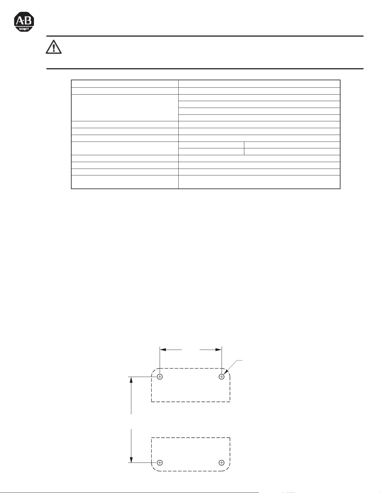
Figure 1
Dual RLS Enclosure Mounting
Flange Hole Dimensions
10.75
(273.1)
6.00
(152.4)
(4) - Ø0.31 (7.9) Dia.
Mounting Holes
Page 2
Remote Lockout Station Cable Specifications
IMPORTANT:
· Cable must have copper conductors only.
· Cable with 600V insulation is required.
· Oil resistant cable is recommended.
· Individual conductors within the cable should be color-coded or otherwise clearly marked (see Table 1).
· Cable must have a shield with a drain wire Similar to: ALPHA wire XTRA-GUARD
- Part No. 25450/9 for #14 AWG, 0.64" O.D.
- Part No. 25440/9 for #16 AWG, 0.61" O.D.
- Part No. 25430/9 for #18 AWG, 0.55" O.D.
Table 1
Suggested Color Scheme for Remote Lockout Station Cable
RLS Terminal Block No.
Wire Color
RLS Terminal Block No.
1 Black
2 Red
3 Blue
4 Orange
GND
IMPORTANT: The maximum total cable length between all of the RLSs and the Control Module in the ElectroGuard® Power Panel shown in
Table 2 must not be exceeded. This may affect the reliable operation of the ElectroGuard®. Consider using an optional Expansion Module if cable
lengths greater than those shown are needed (see Installation and Wiring of the Expansion Module in Chapter 2 of the ElectroGuard® User Manual
Revision 2030-UM003A-EN-P or later).
Table 2
Maximum Allowable Cable Lengths
In North America Outside of North America
Wire
Gauge
14 AWG
Control Module
Connector
RLS1,
RLS1, RLS2, RLS3, RLS4
RLS2, RLS3 19,500
RLS4, RLS5, RLS6
Maximum Total
Cable Length (ft.)
RLS1, RLS2, RLS3 12,250
16 AWG
18 AWG
RLS4, RLS5, RLS6
RLS1, RLS2, RLS3, RLS4
RLS1, RLS2, RLS3 7,650
RLS4, RLS5, RLS6
RLS1, RLS2, RLS3, RLS4
The cable lengths in Table 2 represent the total wire impedance allowed to help ensure proper operation of the safety monitoring relays
used in the isolation system. See Appendix C of the ElectroGuard® User Manual regarding length calculation, conductor sizing and
installation scenarios. Note that each Dual RLS is connected to two separate ElectroGuard® units, and a cable length calculation must
be done for both systems separately. When doing individual calculations, use only the length of the cable connected directly to that unit.
6
7
8
9
Gauge (mm
5,900
19,500
19,500
3,735
12,250
12,250
2,330
7,650
7,650
®
2:
Wire Color
Yellow
Brown
Violet
Gray
Green
Wire
2.1
1.3
0.8
2
)
Maximum Total
Cable Length (m)
5,900
5,900
3,735
3,735
2,330
2,330
23A-85A 110A-1200A
X---
--X
---
---
X
--X
X
---X
---
---
X
X
---X
Wiring the Dual Remote Lockout Station
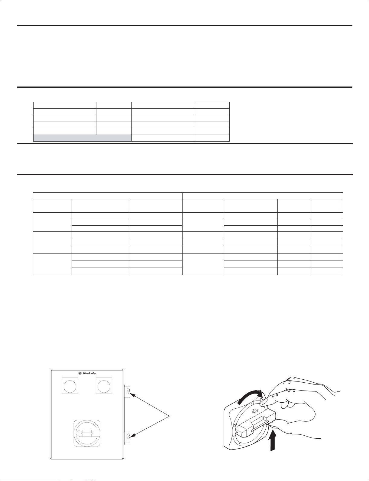
1. Open the RLS enclosure by loosening the two cover clamp screws (See Figure 2).
With the opearting handle held in the OFF position, squeeze the interlock lever and the operation handle held as in Figure 3. Lift the
cover away from the base.
Figure 2
Loosening the Dual RLS Cover Clamp
Figure 3
Operating Interlock Lever to Open Dual RLS
Enclosure
SYSTEM ISOLATED SYSTEM ISOLATED
N
O
Cover
Clamp
Screws
(2)
O
F
F
Page 3

Remote Lockout Station Cable Specifications (Cont'd)
2. Use appropriate environmentally-rated hubs or conduit fittings to connect cables to the Dual RLS enclosure.
Each Dual RLS is furnished with four 1.38 in. (35mm) diameter openings (two on the top and two on the bottom) designed to accept 1 in.
(25.4 mm) conduit fittings or hubs.
IMPORTANT: When installing and wiring the Dual RLS, remove and discard both red plastic cap plugs. If wiring the Dual RLS using one or
both top openings, remove the corresponding closing plug(s) from the top and install in the open bottom hole(s) to maintain the integrity of the
enclosure environmental rating.
IMPORTANT: The cables to the Dual RLS must not be run in a line voltage wireway or run adjacent to power conductors. The cables
must be protected from physical damage. This requires the appropriate conduit outside of the Dual RLS.
IMPORTANT: Connector plugs provided on ElectroGuard
®
Control Modules and Expansion Modules are factory shipped with two
jumper wires installed (see Figure 4).
These two jumper wires must be removed and discarded when wiring to connect a Remote Lockout Station to the connector plug.
Failure to remove the two jumper wires prevents proper operation of the RLS "System Isolated" indicator light.
Figure 4
RLS Connector Plug Jumper Wire
RLS Connector Plug
1 2 3 4 5 6 7 8 9 10 11
Factory installed jumper wires. These
two wires MUST be removed when
wiring an RLS to the connector plug
3. Select an RLS port and connector plug on both ElectroGuard® units to be dedicated to the Dual RLS being installed.
Remove these plugs by firmly grasping their strain relief tabs and pulling straight out from the port.
IMPORTANT: Control Module and Expansion Module connector plugs and ports, with the exclusion of the HV connector in the
Control Module, are factory keyed. This is done to ensure correct plug installation after maintenance or servicing which may have
required the removal of any of the connector plugs.
Installing an RLS connector plug into a port with non-matching keying may damage the connector as well as the Control Module or
Expansion Module port.
(3)
Page 4

Remote Lockout Station Cable Specifications (Cont'd)
Figure 5
Wiring from the RLS Terminal
Block to a Connector Plug on a
Control Module or Expansion
Module
To Control or Expansion Module
(RLS1 to RLS6) or (RLS_A to RLS_J)
12 3 4 5 6 7 89
G
1
N
0
D
RLS Connector Port
Terminals in Control
Module or Expansion
Module
Color Coded
Cable Recommended
Terminal Block
Inside Remote
Lockout Station
Table 3
Continuity Check Table
Remote Lockout
Station Status
G
12 3 4 6 7 89
N
D
Control Module / Expansion Module
Connector Plug
Connection Point Numbers
RLS Connector Plug
For Connecting RLS to Control
Module or Expansion Module
Drain Wire
The fifth terminal of the
Connector Plug is not used
for RLS connection
Braided Cable Shield
Continuity
ON 2 & 7 Yes
ON 3 & 8 Yes
ON 4 & 9 Yes
ON 1 & 6 No
OFF 2 & 7 No
OFF 3 & 8 No
OFF 4 & 9 No
OFF 1 & 6 Yes
1
1 The “System Isolated” light on the front of the RLS has an impedance of about 2K Ohms.
4. Wire each terminal block to its corresponding plug using appropriate cable (see Figure 5, also use Table 1 if using recommended cable).
The wires from the first connected ElectroGuard® system must go to one terminal block, and the wires from the second system must go to
the remaining terminal block.
5. Have one technician operate the Dual RLS while a second technician checks the continuity between connection points on the RLS
connector plug for the Control Module or Expansion Module of the first ElectroGuard® System (per Table 3). If continuity check is
unsatisfactory, review wiring in step 4 for errors and then re-check continuity. When all of the connections between the Dual RLS and the
first ElectroGuard® System are satisfactory, repeat for all connections between the Dual RLS and the second ElectroGuard® System.
6. When both continuity checks are successfully completed, close the Dual RLS enclosure cover, place the cover clamps over the lip on the
edge of the cover and tighten the two cover clamp screws.
7. Commission the unit per Chapter 3 of the ElectroGuard® User Manual Revision 2030-UM003A-EN-P or later.
42052-125-01 (1)
Printed in U.S.A.
 Loading...