

Page 1
System Multiplexer / Permissive Module
(Cat 2030-MLXxxx-SYSx)
ATTENTION: Hazardous Voltage or other forms of energy could be present.
To avoid serious injury or death:
Prior to beginning the installation and wiring process, ensure that all forms of energy to the installation site have been properly turned OFF and locked
out. Follow NFPA 70E requirements.
ATTENTION: This device is a component in a safety system. Do not defeat , tamper with, bypass or alter. Severe injury to personnel could result.
Only qualified service technicians must perform service or maintenance. Resealing of the device is the responsibility of the person or organization
Specifications
Overview
The System Multiplexer / Permissive Module will allow a Remote Lockout Station (RLS) to control up to four ElectroGuard® systems simultaneously. If
there is a need to control more than four
Multiplexer / Permissive Module will accept up to six RLS inputs. A maximum of 60 RLSs can be supported by using six 10 port Expansion Modules. The
System Multiplexer / Permissive Module is also available with a "Permissive" option. The "Permissive" option allows the machine controlling the process or
drive system to bring the machine or process to a predeternined stopping point prior to removal of power by the ElectroGuard® system. Once the
ElectroGuard® system isolates the energy the machine control can not re-energize the ElectroGuard®.
performing the service or maintenance.
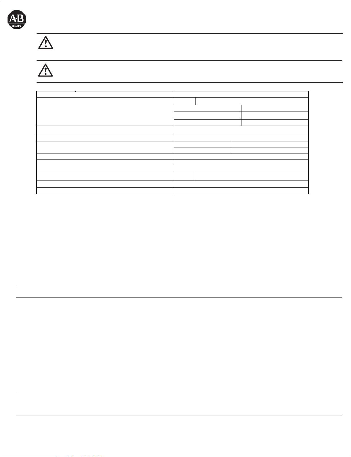
Description Specification
Open Style Dimensions H x W x D
Degree of Protection (By enclosure type designator)
Consult local Allen-Bradley distributor for information regarding
dimensions of enclosed type Expansion Modules
Input Voltage Rating
LED Status Indicator Terminal Blocks
- Torque
4-Port
C = NEMA Type 4X
F = NEMA Type 4
H = IP54
24V DC
24V LED
10.56in x 23in x 6.69in (271.39 x 584.2 x 169.93)
J = NEMA Type 12
N = OPEN STYLE
(Supplied from ElectroGuard® Control Module)
#18 -14 AWG 0.8 -2.1 mm
W = IP65
4 – 5 lb-in. 0.5 - .6 Nm
Operating Ambient Temperature 0…+40° C (+32…+104° F)
Storage Ambient Temperature -10…+60° C (+14…140° F)
Storage Relative Humidity 5…95%, non-condensing
Weight
Agency Certification
Input Frequency, PER1 (7-10)
ElectroGuard® systems the System Multiplexer / Permissive Module can be daisy chained. The System
4-Port
UL, cUL, TUV EN954
28 lb (12.7 kg)
-1 Category 4,
10 - 200 Hz, 10 - 90% duty cycle
2
TUV EN60204
Connector Plugs - Wire Size
-1
Section 1.
Replacement of System Multiplexer / Permissive Module Installed In an Existing Enclosure
To replace an System Multiplexer / Permissive Module that is already installed in an enclosure, perform the following steps:
1. Verify the power to the ElectroGuard® has been turned OFF and locked out.
2. Open the enclosure that contains the System Multiplexer / Permissive Module.
3. Unplug all of the connector plugs attached to the System Multiplexer / Permissive Module. To remove a connector plug, grasp it firmly by its strain
relief & pull straight down.
IMPORTANT: Before installing the replacement System Multiplexer / Permissive Module, remove all of the factory supplied connector plugs from the new module.
They are not used when replacing a previously installed System Multiplexer / Permissive Module.
4. Loosen, but do not remove, the four bolts attaching the module to the enclosure mounting plate.
5A. To remove module mounted vertically -
· Remove the two upper attachment bolts
· Lift the module upward to clear the lower two bolts
· Remove the module from the enclosure
5B. To remove module mounted horizontally -
· Support the module
· Remove the two right side attachment bolts
· Slide the module to the right and remove it from the enclosure
6A. To Install replacement module vertically -
· Lift module into enclosure, slide down onto the two lower bolts and hold it in place
· Insert two upper attachment bolts
· Torque the module attachment bolts to 50-60 lb-in. (5.6-6.8 Nm)
6B. To install replacement module horizontally -
· Lift module into enclosure, slide it to the left and hold it in place
· Insert the two right side attachment bolts
· Torque the module attachment bolts to 50-60 lb-in. (5.6-6.8 Nm)
IMPORTANT: The Control Module and System Multiplexer / Permissive Module connector plugs and ports, with the exclusion of HV connector in the Control Module,
are factory keyed. This is done to ensure correct plug installation after maintenance or servicing which may have required the removal of any of the connector plugs.
Installing an RLS connector plug into a port with non-matching keying may damage the connector as well as the Control Module or System Multiplexer / Permissive
Module port (see Fig. 2 for keying information).
7.
Reattach the existing wired connector plugs to their mating keyed connector ports, ensure they are fully inserted into the
Permissive Module
8. Close the enclosure and turn ON the power to the ElectroGuard®.
9. Commission the unit per Chapter 3 (Revision 2030_UM003A_EN_P or later) of the ElectroGuard® User Manual.
connector ports.
System Multiplexer /
Page 2
Section 2
Installation of an Enclosed System Multiplexer / Permissive Module
To install a factory or customer enclosed System Multiplexer / Permissive Module, perform the following steps:
1. Determine a suitable location for mounting the System Multiplexer / Permissive Module enclosure.
2. Based on the enclosure selected, locate and mark the necessary mounting bolt hole locations on the mounting surface. Drill and tap as needed
for mounting bolts suitable for the support of the enclosed System Multiplexer / Permissive Module.
IMPORTANT: Before mounting an enclosed System Multiplexer / Permissive Module and based upon installation requirements, the openings for conduit or cable
fittings should be made to the enclosure.
If enclosure is customer supplied, conduit or cable fitting openings should be made before installing the open style System Multiplexer / Permissive Module in the
enclosure. This should be done to avoid contaminating the module with fabricating debris.
If enclosure is factory supplied, the System Multiplexer / Permissive Module should be removed from the enclosure, prior to making any openings for conduit or
cable fittings, to help avoid module contamination (see Section 1 for instructions on removing the System Multiplexer / Permissive Module from an enclosure).
3. Support the enclosure while aligning it with the mounting bolt holes.
4. Install enclosure mounting bolts and tighten to torque required for mounting bolt size selected.
5. Mount the System Multiplexer / Permissive Module inside the enclosure (see Section 1 for instructions on installing the System Multiplexer /
Permissive in an enclosure).
6. Select which System Multiplexer / Permissive Module connector plugs will require wiring (see Table 1 and Figures 1 and 3).
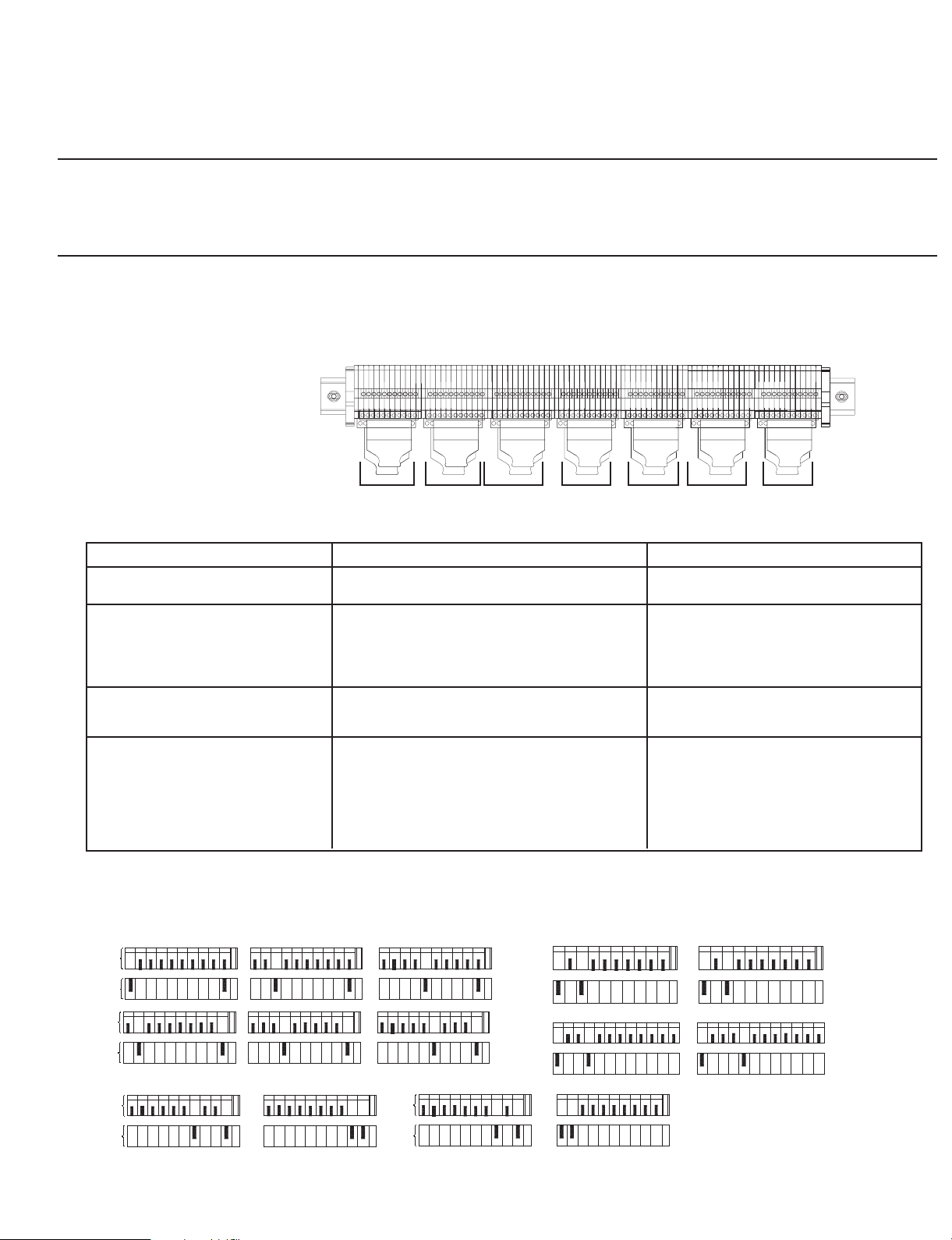
Figure 1
Connectors in
4 Port System Multiplexer /
Permissive Module
Table 1
RLS_A
RLS_B
RLS_C
RLS_D
RLS_E
RLS_F
EXB1
EXB2
EXB3
EXB4
PLC1EXB
PLC2EXB
PER1
PER2
System Multiplexer / Permissive Module Connectors
Connector
RLS S#_A thru RLS S#__F
EXB1 THRU EXB4 System Multiplexer / Permissive Module
PLC1EXB
PER1
The connectors at System Multiplexer / Permissive Module are "Keyed" in order to uniquely identify each connector, in the event they are
removed and re-inserted (See Figure 2).
Description Function
System Multiplexer / Permissive Module Remote
Lockout Station
Connectors to ElectroGuard® Systems (See
Section 3)
Remote Lockout Station status to customer
remote PLC (See Section 5)
Permissive inputs from the PLC and safety relay
output status
Connects Remote Lockout Station to
System Multiplexer / Permissive Module.
Interconnects the System Multiplexer /
Permissive Module to the Control Modules
in ElectroGuard® Systems, or to series
connected System Multiplexer / Permissive
Module.
Connects RLS auxiliary signals to Remote
PLC or optional Remote I/O or
Communication Modules.
The permissive input allows the machine
controlling the process or drive system to
bring the machin or process to a
predetermined stopping point prior to
removal of power by the
system. Output terminals provide the
status of safety relays SR1 and SR7.
ElectroGuard
Figure 2
Keying of RLS Connectors at System Multiplexer / Permissive Module
T
B
P
L
U
G
T
B
P
L
U
G
RLS_A RLS_C RLS_E
123456789
RLS_B
123456789
10 1 2 3 4 5 6 7 8 9
G
N
D
RLS_D
123456789
10
G
N
D
123456789
10
G
N
D
123456789
10
G
N
D
RLS_F
10
G
N
D
10
G
N
D
1234567 9
1234
PER1
PLC1 EXB
5
67 9
8
10
1234567 9
G
N
D
101112
8
1 2 3 4 5 6 7 9 10 11 12
PER2
PLC2 EXB
8
10
G
N
D
G
N
D
8
®
EXB1
123456789
T
B
P
L
U
G
10
G
N
D
EXB3
123456789
EXB2
10
G
N
D
123456789
T
B
P
L
U
G
10
G
N
D
EXB4
123456789
10
G
N
D
7. Follow the specified System Multiplexer / Permissive Module Connector's section (Table 1) to wire connectors.
(2)
Page 3
Section 2 (Cont'd)
Installation of an System Multiplexer / Permissive Module
System Multiplexer / Permissive Module Cable Specifications
IMPORTANT: · Cable must have copper conductors only.
IMPORTANT: The maximum total cable length values shown in Table 2 must not be exceeded, as this may result in unreliable operation of the ElectroGuard®.
Consider using an Expansion Module if cable lengths greater than those shown are needed (See APPENDIX C of the Manual for wiring examples).
· Cable with 600V insulation is required.
· Oil resistant cable is recommended.
· Individual conductors within the cable should be color-coded or otherwise clearly marked (see Table 1).
· Cable must have a shield with a drain wire.
· Type of wire for EXB_ to RLS connector or similar:
ALPHA wire "XTRA-GUARD®2
- Part No. 25450/9 for #14 AWG, 0.64" O.D.
- Part No. 25440/9 for #16 AWG, 0.61" O.D.
- Part No. 25430/9 for #18 AWG, 0.55" O.D.
· Type of wire for PLC1EXB connectors or similar:
ALPHA wire "XTRA-GUARD®2
- Part No. 25450/25 for #14 AWG, 0.98" O.D.
- Part No. 25440/25 for #16 AWG, 0.93" O.D.
- Part No. 25430/25 for #18 AWG, 0.80" O.D.
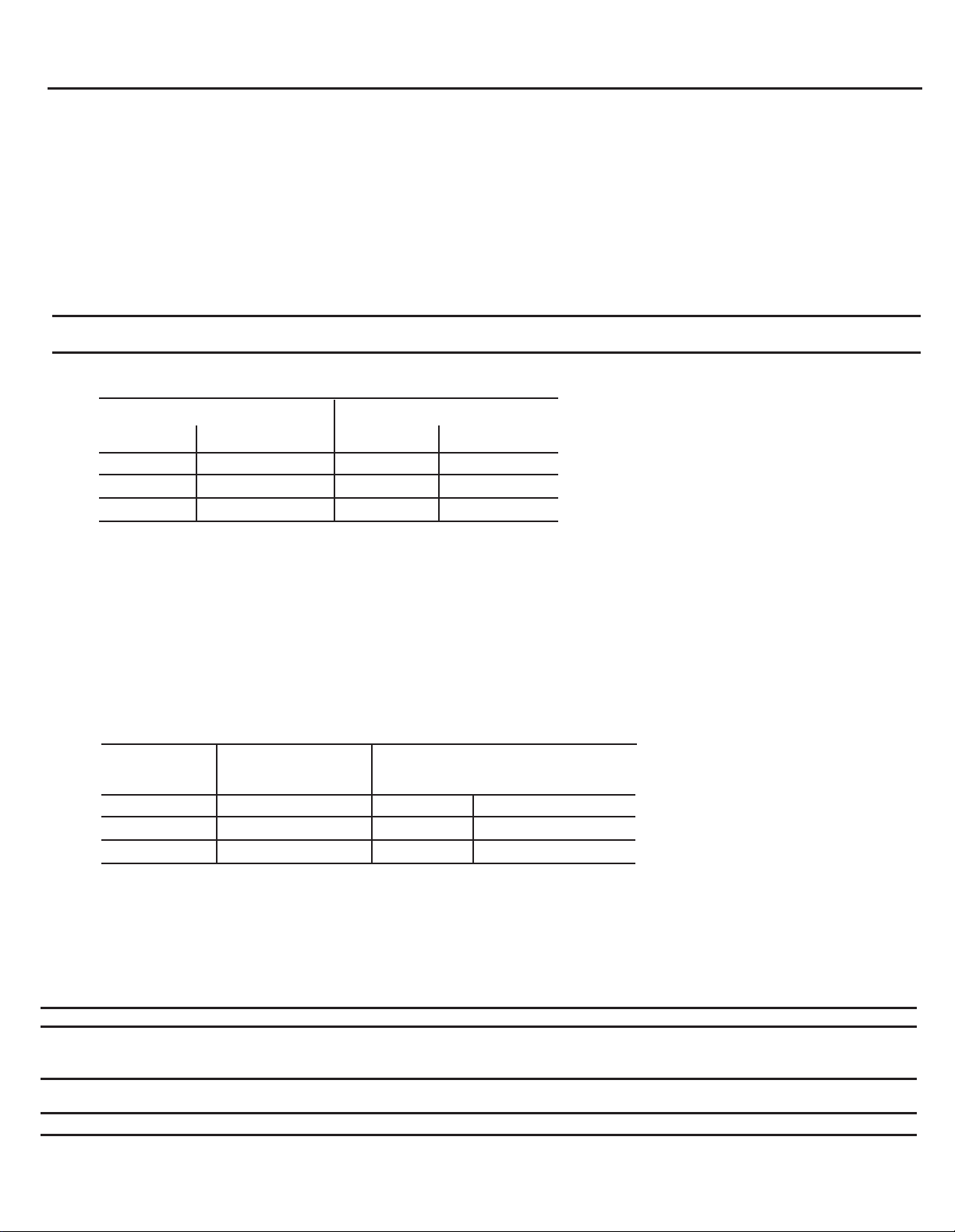
Table 2
Maximum Allowable Cable Lengths for RLS Connected to System Multiplexer / Permissive Module
In North America Outside of North America
Wire Guage
14 AWG
16 AWG 12,500 ft
18 AWG
Maximum
Total Cable Length
20,000 ft
7,750 ft
mm2
2.1
1.3 3,800 m
0.8
Maximum
Total Cable Length
6,100 m
2,360 m
The EXB1 connector provides control power and allows the interface to the System Multiplexer / Permissive Module from the Control Module in the
ElectroGuard® Power Panel. This is accomplished by wiring from the EXB1 connector at the System Multiplexer / Permissive Module to any one of
the RLS ports on the Control Module. The EXB2 thru EXB4 connectors allow the interface of the System Multiplexer / Permissive Module to
additional ElectroGuard® Power Panels. This is accomplished by wiring from the EXB2 thru EXB4 connectors at the System Multiplexer / Permissive
Module to any one of the RLS ports on the Control Module in the other ElectroGuard® Power Panels. See Section 3.
The EXB2 thru EXB4 connectors also allow for the series connection of up to three System Multiplexer / Permissive Modules. This is accomplished
by wiring from the EXB2 thru EXB4 connectors at the System Multiplexer / Permissive Module to the RLS_A connector of the series added System
Multiplexer Module. See Figure 7, Section 3.
Table 3
Maximum Cable Length for System Multiplexer / Permissive Module to Control Module
In North America
AWG
14
16 1.3
18
The cable lengths in Table 2 and Table 3 represent the total wire impedance allowed to help ensure proper operation of the safety monitoring relays
used in the isolation system. Consult Rockwell Automation for cable lengths when series connecting System Multiplexer / Permissive Modules.
NOTE: When series connecting the System Multiplexer / Permissive Modules, two maximum cable lengths must be taken into consideration. One
cable length is the maximum distance from the Control Module to the last series-connectedSystem Multiplexer / Permissive Module. The other cable
length is the RLS circuit length. See Appendix C of the Electro-Guard® User Manual regarding length calculation, conductor sizing and installation
scenarios.
Outside of North
America (mm2)
2.1
0.8
Maximum Distance from Control Module
1,200 ft
750 ft
475 ft
366 m
229 m
145 m
IMPORTANT: The System Multiplexer / Permissive Module can support a maximum of 60 RLSs by using six 10-port Expansion Modules.
IMPORTANT: Connector plugs provided on ElectroGuard® Control Modules and System Multiplexer / Permissive Modules are factory shipped with two jumper
wires installed (see Figure 4). These two jumper wires must be removed and discarded when wiring is performed to connect a Remote Lockout Station to the
connector plug. Failure to remove the two jumper wires prevents proper operation of the RLS "System Isolated" indicator light.
IMPORTANT: When routing the cables from the Remote Lockout Stations to the System Multiplexer / Permissive Module, care must be taken to protect the
cables from physical damage and cable must be run in conduit when outside enclosed.
IMPORTANT: Cables to the System Multiplexer / Permissive Module must not run adjacent to power conductors or be run in a line voltage wireway.
(3)
Page 4

Section 2 (Cont'd)
Installation of an System Multiplexer / Permissive Module
ATTENTION: Hazardous voltage may be present on the load terminals of the ElectroGuard® Power Panel when the System Isolated Light is illuminated
under the following conditions:
· The System Multiplexer is in a Master - Slave (series) configuration.
· RLS(s) are connected to both the master and Slave System Multiplexers.
In this configuration clearly identify the power panel(s) that are being controlled by each RLS.
IMPORTANT: The EXB1 connector must be connected to the Control Module in one of ElectroGuard® Systems connected to the System Multiplexer /
Permissive Module. The System Multiplexer / Permissive Module derives its control power through the EXB1 connector.
IMPORTANT: The System Multiplexer / Permissive Module can accomodate up to a maximum of 6 RLSs. If less than the maximum number of RLSs is
needed for the installation, the unused RLS connectors must be jumpered out. The jumpers are necessary to simulate an RLS in the ON position. For example, if
RLS S#_F is not needed:
1) Remove RLS Plug, firmly grip the strain relief pad holding the RLS S#_F.
2) Remove the connector by pulling it away from the System Multiplexer / Permissive Module.
3) Once the jumpers are installed, re-insert the connector plug into the System Multiplexer / Permissive Module.
Select the RLS port and connector plug on the System Multiplexer / Permissive Module to be dedicated to the RLS being installed. Remove
these plugs by firmly grasping their strain relief tabs and pulling straight from the port. Wire each terminal block to its corresponding plug
using appropriate cable (see Figure 3).
Figure 3
Remote Lockout Station Wiring at System Multiplexer / Permissive Module
(RLS1 to RLS6) or (RLS_A to RLS_F)
G
1
123456789
N
0
D
RLS Connector Port Terminals
in Control Module or
Multiplexer / Permissive
Module
Color Coded
Cable Recommended
Terminal Block
Inside Remote
Lockout Station
Figure 4
RLS Connector Plug Jumper Wire
System
12 3 4 6 7 89
Locations
RLS Connector Plug
1 2 3 4 5 6 7 8 9 10 11
RLS Connector Port Terminals in
Control Module or
Multiplexer / Permissive Module
Drain Wire
The fifth terminal of the
Connector Plug is not used
for RLS connection
Braided Cable Shield
G
N
D
System
(4)
Factory installed jumper wires. These two
wires MUST be removed when wiring an
RLS to the connector plug
Page 5

Section 3
Wiring the System Multiplexer / Permissive Module to the Control Module (EXB1 Connectors)
ATTENTION: Hazardous voltage may be present on the load terminals of the ElectroGuard® Power Panel when the System Isolated Light is illuminated if
the jumper wires (see Figure 5) are not removed when multiple Power Panels are connected. The EXB2 thru EXB4 connector plugs provided on the
System Multiplexer / Permissive Module are factory shipped with two jumper wires installed (see Figure 5). These two jumper wires must be removed
and discarded when wiring is performed to connect an ElectroGuard® Power Panel. Failure to remove the two jumper wires will cause the System
Multiplexer / Permissive Module not to receive the proper system isolated status signals from the Power Panels and the System Isolated light may
illuminate when all power Panels have not gone to the isolated state.
IMPORTANT: The EXB1 connector must be connected to the Control Module in one of ElectroGuard® Systems connected to the System Multiplexer /
Permissive Module. The System Multiplexer / Permissive Module derives its control power through the EXB1 connector.
Figure 5
EXB2-4 Connector Pug Jumper Wire Locations
EXB2 thru EXB4 Connector Plugs
12 34 56 78 910G
1. Select wire size to connect the System Multiplexer / Permissive Module to the Control Module or to series connect an System Multiplexer
Module based upon Table 3.
2. Install the interconnecting wiring between the EXB connector plug on the System Multiplexer / Permissive Module and the RLS connector
plug selected for connection to the Control Module (see Figures 6). When series connecting the System Multiplexer Module, install the
interconnecting wiring between the EXB2, 3 or 4 connector plug to the RLS_A connector plug on the series connected System Multiplexer
Module.
Figure 6A
Wiring the System Multiplexer / Permissive Module
EXB1 Connector Plug to the Control Module
Any RLS Port on Control Module
EXB1 Terminal Block
on System Multiplexer /
12 34 56 78 910G
RLS Terminal Block
on Control Module
12 34 56 78 910G
Permissive Module
EXB1 Connector Plug
on System Multiplexer /
Permissive Module
TO RLS (3)
TO RLS (1)
TO RLS (6)
TO RLS (5)
TO RLS (4)
TO RLS (10)
TO RLS (9)
TO RLS (8)
GND
1
Indicates Connection Point
RLS Connector Plug
on Control Module
FROM EXB1 (1)
11
FROM EXB1 (6)
FROM EXB1 (5)
FROM EXB1 (4)
FROM EXB1 (3)
GND
FROM EXB1 (10)
FROM EXB1 (9)
FROM EXB1 (8)
Shield
on Connection Plug
Figure 6B
Wiring the System Multiplexer / Permissive Module
EXB2 thru EXB4 Connector Plug to the Control Module
EXB_ Terminal Block
on System Multiplexer /
12 34 56 78 910G
Permissive Module
EXB_ Connector Plug
on System Multiplexer /
Permissive Module
TO RLS (3)
TO RLS (1)
TO RLS (4)
TO RLS (8)
TO RLS (6)
TO RLS (9)
GND
1
Indicates Connection Point
on Connection Plug
(5)
RLS Terminal Block
on Control Module
RLS Connector Plug
on Control Module
Any RLS Port on Control Module
12 34 56 78 910G
GND
FROM EXB_ (9)
FROM EXB_ (8)
FROM EXB_ (6)
FROM EXB_ (4)
FROM EXB_ (3)
FROM EXB_ (1)
11
Shield
Page 6

Section 3 (Cont'd)
Wiring the Series Connected System Multiplexer Module to the System Multiplexer / Permissive Module (EXB2-4 Connector)
Figure 7
Series Wiring the System Multiplexer Module
RLS_A Terminal Block
on series connected
System Multiplexer
12 34 56 78 910G
Module
RLS_A Connector Plug
on series connected
System Multiplexer
TO EXB_ (1)
TO EXB_ (3)
TO EXB_ (6)
TO EXB_ (4)
Module
TO EXB_ (9)
TO EXB_ (8)
GND
EXB2-4 terminal Block on System Multiplexer / Permissive Module
EXB2-4 Terminal Block
on System Multiplexer /
12 34 56 78 910G
Permissive Module
EXB2-4 Connector Plug
on System Multiplexer /
Permissive Module
FROM RLS_A (4)
FROM RLS_A (3)
FROM RLS_A (1)
FROM RLS_A (6)
GND
FROM RLS_A (9)
FROM RLS_A (8)
1
Indicates Connection Point
11
Shield
on Connection Plug
3. Insert the RLS connector plug (wired to the end of the EXB interface cable) into the selected RLS port of the Control Module. Do not connect the EXB
plug to the new System Multiplexer / Permissive Module until successfully completing the following continuity check of the cable.
4. Check cable continuity at connection points on the EXB connector plug as listed in Table 5.
· Note all RLS are turned ON except the one that is switched ON or OFF for testing.
· If continuity check is unsatisfactory, review wiring done in step 2 for errors and then re-check continuity.
Table 5
EXB Cable Continuity
Check Table
Remote Lockout
Station Status
ON
ON
ON
ON
ON
OFF
EXB Connector Plug
Connection Point Numbers
1 & 6
3 & 8
4 & 9
5 & 10
10 & GND
1 & 6
Continuity
Yes ➊
Yes
Yes
No
Yes
Yes ➌
OFF
OFF
OFF
OFF
3 & 8
4 & 9
5 & 10
10 & GND
No
No
No
Yes
➊ The "ML" pilot light in the Control Module has an impedance of about 60 to 70 Ohms.
➋ With 23-85A Control Module, check with positive meter lead (+) on connection point 5 and negative meter lead (-)
on connection point 10, the impedance should be about 110K Ohms. With 110-1200A Control Module, open fuse
covers on 14FU & 16FU fuse holders before checking continuity. Impedance should be about 900K Ohms.
➌ The "System Isolated" light on the front of the RLS has an impedance of about 2K Ohms.
5. When continuity check is successfully completed, insert the EXB connector plug into the EXB port on the new System Multiplexer / Permissive Module.
If RLS status output signals are not required, close and secure the cover of the System Multiplexer / Permissive Module enclosure.
IMPORTANT: If RLS status signals are required, proceed to Section 5 for instructions on wiring of the PLC1EXB connector plug on the System Multiplexer /
Permissive Module before performing Step 6. If using the Permissive option, proceed to Section 4 for instructions on wiring the System Multiplexer / Permissive Module
to the PLC before performing Step 6.
6. Commision the unit per Chapter 3 of the ElectroGuard User Manual Revision 2030_UM003A_EN_P or later.
(6)
Page 7

Section 4
Wiring the Permissive Option to the PLC (PER1)
ATTENTION: Hazardous Voltage; Voltage from sources other than the ElectoGuard® may be present on the PER1.
Sequence of events for System Multiplexer / Permissive Module option:
1. The PLC outputs are connected to the System Multiplexer / Permissive Module terminals PER1 (7) and (8) and PER1 (9) and (10), see Figure 8.
The outputs must be pulsed at a rate of 10 - 200Hz with a duty cycle of 10 - 90%. This signal is used by the System Multiplexer / Permissive Module
as a "heart beat" which holds the output of the System Multiplexer / permissive Module in the "ON" or closed state. Thus holding the ElectroGuard
system in the "ON" or Non-isolated state.
2. When a RLS is turned OFF, a signal is transmitted to the control system via a PLC connection on the RLS auxiliary contacts. Note that the outputs
of the System Multiplexer / Permissive Module remain in the "ON" or closed state.
3. When the customer's control system is at a predetermined stopping point, the control system, via the PLC outputs are turned to an off state (no heart
beat) and the outputs of the System Multiplexer / Permissive Module are then switched to the "OFF" or open state.
4. The system isolation function is then initiated on all of the ElectroGuard
®
5. When all of the ElectroGuard
systems are in the isolated state, the System Multiplexer / Permissive Module sends the "Isolated" signal to the RLS
and the RLS System Isolated pilot light on the RLS will be illuminated. The RLS now has control of the ElectroGuard® and the energy can only be
restored to the machine or process by switching all of the RLSs connected to the multiplexers to the "on" state.
The output status of safety relay SR1 can be monitored on connector plug PER1 terminals 1 and 2 (see Figure 9). When the System Multiplexer /
Permissive Module is instructing the ElectroGuard® systems to "Isolate", a set of contacts will open between terminals PER1 (1) and (2).
The output status of safety relay SR7 can be monitored on connector plug PER1 terminals 3 and 4 (see Figure 9). When the PLC is allowing the
ElectroGuard® systems to "Isolate", a set of contacts will close between terminals PER1 (3) and (4).
®
systems simultaneously.
®
Figure 8
Wiring the System Multiplexer / Permissive Module to the PLC
PER1
Terminal Block
PER1
Connector Plug
12 34 56 78 910
12 34 56 78 910
G
N
D
G
N
D
Figure 9
Wiring the System Multiplexer / Permissive Module to the PLC
PER1
Terminal Block
PER1
Connector Plug
12 34 56 78 910
12 34 56 78 910
G
N
D
G
N
D
Drain Wire
N
P
N
P
Output 1
Output 2
PLC
Terminal Block
SR1
SR7
Output Status
(7)
Page 8

Section 5.
Wiring for the RLS Status Signals from PLC1EXB Connector
The System Multiplexer / Permissive Modules can provide status signals for each Remote Lockout Station connected to them. These signals are
provided via an auxiliary contact within the RLS. When the RLS is in the OFF position, the auxiliary contact will be open. Conversely, when the RLS
is in the ON position, the auxiliary contact will be closed. These status signals can be wired to a customer supplied remote PLC, or to the optional
Remote I/O or communication modules installed in the ElectroGuard power panel.
See Figure 10 for wiring of the PLC1EXB connector in the System Multiplexer / Permissive Module to provide RLS status output signals.
Figure 10
PLC1EXB Connections at System Multiplexer / System Module
PLC1EXB
Terminal Block
in System Multiplexer /
Permissive Module
PLC1EXB
Connector Plug
in System Multiplexer /
Permissive Module
12 34 56 78 9101112
RLS_A RLS_F
RLS_B
24V DC MAX.
RLS_C
RLS_E
RLS_D
42052-164-01 (1)
Printed in U.S.A.
 Loading...