

Page 1

Modular
DeviceNet
Starter Auxiliary I/O
(Modular DSA I/O)
Bulletin 198
User Manual
Page 2

Important User Information
Because of the variety of uses for the products described in this publication, those responsible
for the application and use of this control equipment must satisfy themselves that all
necessary steps have been taken to assure that each application and use meets all performance
and safety requirements, including any applicable laws, regulations, codes and standards.
The illustrations, charts, sample programs and layout examples shown in this guide are
intended solely for purposes of example. Since there are many variables and requirements
associated with any particular installation, Allen-Bradley does not assume responsibility or
liability (to include intellectual property liability) for actual use based upon the examples
shown in this publication.
Allen-Bradley publication SGI-1.1, Safety Guidelines for the Application, Installation and Maintenance
of Solid-State Control (available from your local Allen-Bradley office), describes some important
differences between solid-state equipment and electromechanical devices that should be taken
into consideration when applying products such as those described in this publication.
Reproduction of the contents of this copyrighted publication, in whole or part, without
written permission of Rockwell Automation, is prohibited.
Page 3

Throughout this manual we use notes to make you aware of safety considerations:
ATTENTION
Identifies information about practices or circumstances that can lead
to personal injury or death, property damage or economic loss
!
Attention statements help you to:
• identify a hazard
• avoid a hazard
• recognize the consequences
IMPORTANT
Allen-Bradley, RSNetWorx, PLC, SLC, Distributed Starters, and Modular-DSA are registered trademarks of Rockwell Automation
DeviceNet is a trademark of the Open DeviceNet Vendor Association (ODVA).
European Union Directive Compliance
If this product has the CE mark it is approved for installation within the European Union and
EEA regions. It has been designed and tested to meet the following directives.
Identifies information that is critical for successful application and
understanding of the product.
EMC Directive
This product is tested to meet Council Directive 89/336/EEC Electromagnetic
Compatibility (EMC) using the following standards, in whole or in part, documented in a
technical construction file:
• EN 50081-2 EMC — Generic Emission Standard, Part 2 — Industrial Environment
• EN 50082-2 EMC — Generic Immunity Standard, Part 2 — Industrial Environment
This product is intended for use in an industrial environment.
Page 4

Low Voltage Directive
This product is also designated to meet Council Directive 73/23/EEC Low Voltage, by
applying the safety requirements of EN 60947-5-1 — Low Voltage Switchgear and Control
Gear — Control Circuit Devices and Switching Elements — Electromechanical Control
Circuit Devices.
This equipment is classified as open equipment and must be mounted in an enclosure during
operation to provide safety protection.
Page 5

Preface
Manual Objectives
The purpose of this manual is to provide you with the necessary information to apply the
Bulletin 198 Modular DeviceNet Starter Auxiliary (Modular-DSA I/O System). Described
in this manual are methods for installing, configuring, and troubleshooting the Bulletin 198
System of components.
IMPORTANT
Read this manual in its entirety before installing, operating, servicing,
or configuring the Bulletin 198 Modular-DSA I/O System.
Intended Audience
This manual is intended for qualified personnel responsible for the setup and service of these
devices. You must have previous experience with and a basic understanding of
communications terminology, configuration procedures, required equipment, and safety
precautions.
You should understand the DeviceNet network operations, including how slave devices
operate on the network and communicate with a DeviceNet master.
You should be familiar with the use of the RSNetWorx for DeviceNet Software (Cat.
No. 9357-DNET L3) for network configuration. This software package is referred to often in
this manual.
IMPORTANT
Read the DeviceNet Cable System Planning and Installation
Manual, Pub. No. 1485-6.7.1, in its entirety before planning and
installing a DeviceNet System. If the network is not installed
according to this document, unexpected operation and intermittent
failures can occur.
If this manual is not available, please contact either the local
Allen-Bradley Distributor or sales Office to request a copy. Copies
may also be ordered from the Rockwell Automation Bookstore. The
Bookstore can be contacted via the Internet from the Allen-Bradley
home page at http://www.ab.com.
Publication 198-UM001B-EN-P September 2001
Page 6

2 Preface
ATTENTION
Only personnel familiar with DeviceNet devices and associated
equipment should plan or implement the installation, start-up,
configuration, and subsequent maintenance of the Modular-DSA I/O
System. Failure to comply may result in personal injury and/or
equipment damage.
!
Vocabulary
Note the following references throughout this manual:
• Bulletin 198 with its options is referred to as the Modular-DSA I/O System.
• DeviceNet is referred to as Dnet or DNET.
• The Programmable Logic Controller is referred to as the Programmable controller,
PLC controller, or SLC controller.
• Earth Ground is referred to as GND.
• The National Electrical Code is referred to as NEC.
Reference Manuals
Product Reference Manuals
For RSNetWorx for DeviceNet Software Pub. No. 1787-6.5.3
For SLC 500 and 1747-SDN Pub. No. 1747-5.8
For PLC-5 and 1771-SDN Pub. No. 1771-5.14
For DeviceNet Cables and Components Pub. No. DN-2.5
(RSNetWorx Software Manual,)
(DeviceNet Scanner Module Installation Instructions)
(DeviceNet Scanner Module Installation Instructions)
(DeviceNet Overview)
Publication 198-UM001B-EN-P September 2001
Page 7

Table of Contents
Preface
Manual Objectives . . . . . . . . . . . . . . . . . . . . . . . . . . . . . . . . . . . . . . . . . . . . . . . . . . . . . . . . . P-1
Intended Audience . . . . . . . . . . . . . . . . . . . . . . . . . . . . . . . . . . . . . . . . . . . . . . . . . . . . . . . . . P-1
Vocabulary . . . . . . . . . . . . . . . . . . . . . . . . . . . . . . . . . . . . . . . . . . . . . . . . . . . . . . . . . . . . . . . P-2
Reference Manuals . . . . . . . . . . . . . . . . . . . . . . . . . . . . . . . . . . . . . . . . . . . . . . . . . . . . . . . . . P-2
Chapter 1 — Product Overview
Chapter Objectives. . . . . . . . . . . . . . . . . . . . . . . . . . . . . . . . . . . . . . . . . . . . . . . . . . . . . . . . . . 1-1
System Description. . . . . . . . . . . . . . . . . . . . . . . . . . . . . . . . . . . . . . . . . . . . . . . . . . . . . . . . . . 1-1
Cat. Nos. . . . . . . . . . . . . . . . . . . . . . . . . . . . . . . . . . . . . . . . . . . . . . . . . . . . . . . . . . . . . . . . . . . 1-4
DeviceNet Compatibility . . . . . . . . . . . . . . . . . . . . . . . . . . . . . . . . . . . . . . . . . . . . . . . . . . . . . 1-4
Chapter 2 — Installation
Chapter Objectives. . . . . . . . . . . . . . . . . . . . . . . . . . . . . . . . . . . . . . . . . . . . . . . . . . . . . . . . . . 2-1
Storage and Operation . . . . . . . . . . . . . . . . . . . . . . . . . . . . . . . . . . . . . . . . . . . . . . . . . . . . . . . 2-1
Electrostatic Discharge . . . . . . . . . . . . . . . . . . . . . . . . . . . . . . . . . . . . . . . . . . . . . . . . . . . . . . 2-2
Remove Power . . . . . . . . . . . . . . . . . . . . . . . . . . . . . . . . . . . . . . . . . . . . . . . . . . . . . . . . . . . . . 2-2
Approximate Dimensions . . . . . . . . . . . . . . . . . . . . . . . . . . . . . . . . . . . . . . . . . . . . . . . . . . . . 2-3
Module Installation. . . . . . . . . . . . . . . . . . . . . . . . . . . . . . . . . . . . . . . . . . . . . . . . . . . . . . . . . . 2-4
DIN Rail Mounting . . . . . . . . . . . . . . . . . . . . . . . . . . . . . . . . . . . . . . . . . . . . . . . . . . . . . . . . . 2-4
Gland Plate Mounting . . . . . . . . . . . . . . . . . . . . . . . . . . . . . . . . . . . . . . . . . . . . . . . . . . . . . . . 2-5
Wiring Diagrams. . . . . . . . . . . . . . . . . . . . . . . . . . . . . . . . . . . . . . . . . . . . . . . . . . . . . . . . . . . . 2-7
Chapter 3 —Operation
Chapter Objectives . . . . . . . . . . . . . . . . . . . . . . . . . . . . . . . . . . . . . . . . . . . . . . . . . . . . . 3-1
Basic Configuration . . . . . . . . . . . . . . . . . . . . . . . . . . . . . . . . . . . . . . . . . . . . . . . . . . . . . 3-1
DeviceNet MAC ID(node address) . . . . . . . . . . . . . . . . . . . . . . . . . . . . . . . . . . . . . . . . 3-5
DeviceNet Module Configuration Parameters . . . . . . . . . . . . . . . . . . . . . . . . . . . . . . . . 3-8
Autobaud . . . . . . . . . . . . . . . . . . . . . . . . . . . . . . . . . . . . . . . . . . . . . . . . . . . . . . . . . . . . . 3-9
Choosing an I/O Assembly Format . . . . . . . . . . . . . . . . . . . . . . . . . . . . . . . . . . . . . . . 3-10
Mapping to the Scanner. . . . . . . . . . . . . . . . . . . . . . . . . . . . . . . . . . . . . . . . . . . . . . . . . 3-11
Advanced Topics . . . . . . . . . . . . . . . . . . . . . . . . . . . . . . . . . . . . . . . . . . . . . . . . . . . . . . . . . . 3-14
Registering New Devices. . . . . . . . . . . . . . . . . . . . . . . . . . . . . . . . . . . . . . . . . . . . . . . . 3-14
COS Mask Parameter . . . . . . . . . . . . . . . . . . . . . . . . . . . . . . . . . . . . . . . . . . . . . . . . . . 3-19
I/O Module Configuration Parameters . . . . . . . . . . . . . . . . . . . . . . . . . . . . . . . . . . . . 3-20
DeviceNet Explicit Messaging . . . . . . . . . . . . . . . . . . . . . . . . . . . . . . . . . . . . . . . . . . . 3-26
DeviceNet I/O Messaging . . . . . . . . . . . . . . . . . . . . . . . . . . . . . . . . . . . . . . . . . . . . . . 3-27
Mod/Net Status LED . . . . . . . . . . . . . . . . . . . . . . . . . . . . . . . . . . . . . . . . . . . . . . . . . . 3-31
I/O Status LED. . . . . . . . . . . . . . . . . . . . . . . . . . . . . . . . . . . . . . . . . . . . . . . . . . . . . . . 3-32
Page 8

ii Table of Contents
Chapter 4 — Programming
Chapter Objectives . . . . . . . . . . . . . . . . . . . . . . . . . . . . . . . . . . . . . . . . . . . . . . . . . . . . . . . . . 4-1
I/O Mapping . . . . . . . . . . . . . . . . . . . . . . . . . . . . . . . . . . . . . . . . . . . . . . . . . . . . . . . . . . . . . . 4-1
Verifying the Input Assembly. . . . . . . . . . . . . . . . . . . . . . . . . . . . . . . . . . . . . . . . . . . . . 4-4
Verifying the Output Assembly . . . . . . . . . . . . . . . . . . . . . . . . . . . . . . . . . . . . . . . . . . . 4-6
Programming Explicit Messages . . . . . . . . . . . . . . . . . . . . . . . . . . . . . . . . . . . . . . . . . . 4-8
Chapter 5 — Specifications
198-DNG, 198-DN (DeviceNet Modules) . . . . . . . . . . . . . . . . . . . . . . . . . . . . . . . . . . . . . . 5-1
Mod/Net Status LED . . . . . . . . . . . . . . . . . . . . . . . . . . . . . . . . . . . . . . . . . . . . . . . . . . . . . . . 5-1
I/O Status LED . . . . . . . . . . . . . . . . . . . . . . . . . . . . . . . . . . . . . . . . . . . . . . . . . . . . . . . . . . . 5-3
198-DNP (Mini DIN Pass-Through) . . . . . . . . . . . . . . . . . . . . . . . . . . . . . . . . . . . . . . . . . . . 5-6
198-IB2S (Sensor Module) . . . . . . . . . . . . . . . . . . . . . . . . . . . . . . . . . . . . . . . . . . . . . . . . . . . 5-7
198-IB4 (4-Input DC Module) . . . . . . . . . . . . . . . . . . . . . . . . . . . . . . . . . . . . . . . . . . . . . . . 5-10
198-IB4S Series A (4-Input DC Module DS). . . . . . . . . . . . . . . . . . . . . . . . . . . . . . . . . . . . 5-13
198-IA2 (2-Input AC Module) . . . . . . . . . . . . . . . . . . . . . . . . . . . . . . . . . . . . . . . . . . . . . . . 5-16
198-IA2-G4 Series A (AC Sensor Module) . . . . . . . . . . . . . . . . . . . . . . . . . . . . . . . . . . . . . 5-19
198-IA1-G4 9000 Series A (9000 Sensor Module) . . . . . . . . . . . . . . . . . . . . . . . . . . . . . . . 5-22
198-OW2S (2-Relay Output Gland) . . . . . . . . . . . . . . . . . . . . . . . . . . . . . . . . . . . . . . . . . . . 5-25
198-OW2 Series A (2-Relay Output DIN Module). . . . . . . . . . . . . . . . . . . . . . . . . . . . . . . 5-27
198-OW2-G4 Series A (Relay Valve Module) . . . . . . . . . . . . . . . . . . . . . . . . . . . . . . . . . . . 5-30
198-OW2S-Q5 Series A (DeviceNet Valve Module). . . . . . . . . . . . . . . . . . . . . . . . . . . . . . 5-33
198-IA2XOW1 Series A and B (AC Starter Module) . . . . . . . . . . . . . . . . . . . . . . . . . . . . . 5-35
198-IB2XOB1 Series A and B (DC Starter Module). . . . . . . . . . . . . . . . . . . . . . . . . . . . . . 5-41
198-IB2XOW1 Series A and B (DC Input Relay Output Module) . . . . . . . . . . . . . . . . . . 5-48
198-IB2XOB5S Series A (Drive Preset Speed Module) . . . . . . . . . . . . . . . . . . . . . . . . . . . 5-55
198-IB2XOB2S-Q5 Series A (Drive Preset Speed Module) . . . . . . . . . . . . . . . . . . . . . . . . 5-61
198-G1P (Gland Plates) . . . . . . . . . . . . . . . . . . . . . . . . . . . . . . . . . . . . . . . . . . . . . . . . . . . . 5-67
Chapter 6 — Troubleshooting
Chapter Objectives . . . . . . . . . . . . . . . . . . . . . . . . . . . . . . . . . . . . . . . . . . . . . . . . . . . . . . . . . 6-1
Diagnostics. . . . . . . . . . . . . . . . . . . . . . . . . . . . . . . . . . . . . . . . . . . . . . . . . . . . . . . . . . . . . . . . 6-1
Red I/O Light . . . . . . . . . . . . . . . . . . . . . . . . . . . . . . . . . . . . . . . . . . . . . . . . . . . . . . . . . . . . . 6-1
Red I/O Light — Noise . . . . . . . . . . . . . . . . . . . . . . . . . . . . . . . . . . . . . . . . . . . . . . . . . . . . . 6-2
DeviceNet Connection and Autobaud. . . . . . . . . . . . . . . . . . . . . . . . . . . . . . . . . . . . . . . . . . 6-2
Low DeviceNet Voltage . . . . . . . . . . . . . . . . . . . . . . . . . . . . . . . . . . . . . . . . . . . . . . . . . . . . . 6-2
Excessive Number of Modules. . . . . . . . . . . . . . . . . . . . . . . . . . . . . . . . . . . . . . . . . . . . . . . . 6-3
Invalid ID. . . . . . . . . . . . . . . . . . . . . . . . . . . . . . . . . . . . . . . . . . . . . . . . . . . . . . . . . . . . . . . . . 6-3
Checksum Error . . . . . . . . . . . . . . . . . . . . . . . . . . . . . . . . . . . . . . . . . . . . . . . . . . . . . . . . . . . 6-3
Discontinuity Error . . . . . . . . . . . . . . . . . . . . . . . . . . . . . . . . . . . . . . . . . . . . . . . . . . . . . . . . . 6-3
I/O Module Current Errors . . . . . . . . . . . . . . . . . . . . . . . . . . . . . . . . . . . . . . . . . . . . . . . . . . 6-4
Publication 198-UM001B-EN-P September 2001
Page 9

Table of Contents iii
Sensor Undervoltage Error . . . . . . . . . . . . . . . . . . . . . . . . . . . . . . . . . . . . . . . . . . . . . . . . . . . 6-4
Shorted and Open Sensor Detection. . . . . . . . . . . . . . . . . . . . . . . . . . . . . . . . . . . . . . . . . . . . 6-4
Appendix A — DeviceNet Information
DeviceNet Module Introduction . . . . . . . . . . . . . . . . . . . . . . . . . . . . . . . . . . . . . . . . . . . . . . A-1
Product Identification . . . . . . . . . . . . . . . . . . . . . . . . . . . . . . . . . . . . . . . . . . . . . . . . . . . . . . A-1
Product Type . . . . . . . . . . . . . . . . . . . . . . . . . . . . . . . . . . . . . . . . . . . . . . . . . . . . . . . . . A-1
Product Code . . . . . . . . . . . . . . . . . . . . . . . . . . . . . . . . . . . . . . . . . . . . . . . . . . . . . . . . . A-1
Certifications and Standards . . . . . . . . . . . . . . . . . . . . . . . . . . . . . . . . . . . . . . . . . . . . . . . . . A-1
Certifications . . . . . . . . . . . . . . . . . . . . . . . . . . . . . . . . . . . . . . . . . . . . . . . . . . . . . . . . . A-1
Standards . . . . . . . . . . . . . . . . . . . . . . . . . . . . . . . . . . . . . . . . . . . . . . . . . . . . . . . . . . . . A-1
DeviceNet Implementation . . . . . . . . . . . . . . . . . . . . . . . . . . . . . . . . . . . . . . . . . . . . . . . . . . A-2
Operating Modes . . . . . . . . . . . . . . . . . . . . . . . . . . . . . . . . . . . . . . . . . . . . . . . . . . . . . . . . . . A-2
Power-Up Reset Mode . . . . . . . . . . . . . . . . . . . . . . . . . . . . . . . . . . . . . . . . . . . . . . . . . A-2
Run Mode. . . . . . . . . . . . . . . . . . . . . . . . . . . . . . . . . . . . . . . . . . . . . . . . . . . . . . . . . . . . A-3
Error Mode . . . . . . . . . . . . . . . . . . . . . . . . . . . . . . . . . . . . . . . . . . . . . . . . . . . . . . . . . . A-3
I/O Error Mode . . . . . . . . . . . . . . . . . . . . . . . . . . . . . . . . . . . . . . . . . . . . . . . . . . . . . . A-4
I/O Idle Mode . . . . . . . . . . . . . . . . . . . . . . . . . . . . . . . . . . . . . . . . . . . . . . . . . . . . . . . . A-4
Object Definitions . . . . . . . . . . . . . . . . . . . . . . . . . . . . . . . . . . . . . . . . . . . . . . . . . . . . . . . . . A-4
DeviceNet Objects. . . . . . . . . . . . . . . . . . . . . . . . . . . . . . . . . . . . . . . . . . . . . . . . . . . . . A-4
Identity Object — Class ID (01hex). . . . . . . . . . . . . . . . . . . . . . . . . . . . . . . . . . . . . . . A-4
DeviceNet Object — Class ID (03hex) . . . . . . . . . . . . . . . . . . . . . . . . . . . . . . . . . . . . A-6
Assembly Object — Class ID (04hex) . . . . . . . . . . . . . . . . . . . . . . . . . . . . . . . . . . . . . A-7
Connection Object — Class ID (05hex) . . . . . . . . . . . . . . . . . . . . . . . . . . . . . . . . . . A-16
Discrete Input Point Object — Class ID (08hex) . . . . . . . . . . . . . . . . . . . . . . . . . . . A-17
Acknowledge Handler Object — Class ID (2Bhex) . . . . . . . . . . . . . . . . . . . . . . . . . A-19
DeviceNet Interface Object — Class ID (B4hex) . . . . . . . . . . . . . . . . . . . . . . . . . . . A-20
Publication 198-UM001B-EN-P September 2001
Page 10

Chapter
1
Product Overview
Chapter Objectives
This chapter contains the following information:
• System description
• DeviceNet compatibility
• European Union Directive compliance
System Description
The Bulletin 198 Modular-DSA I/O System is a cost-effective, glandular I/O system
designed specifically for Distributed Starters (Figure 1.2) and general starter panels. The
Modular-DSA I/O System consists of a DeviceNet module followed by up to 16 I/O
modules. The modules can be arranged in any combination and appear as one node on a
DeviceNet network. Since the Modular-DSA I/O System was designed specifically for
Distributed Starters, it not only provides the ability to control and monitor devices such as
motor starters, sensors, solenoids and load feeders, but also provides for cable connections to
those devices, eliminating the expense and problems of traditional wiring.
Publication 198-UM001B-EN-P September 2001
Page 11
Product Overview 1-2
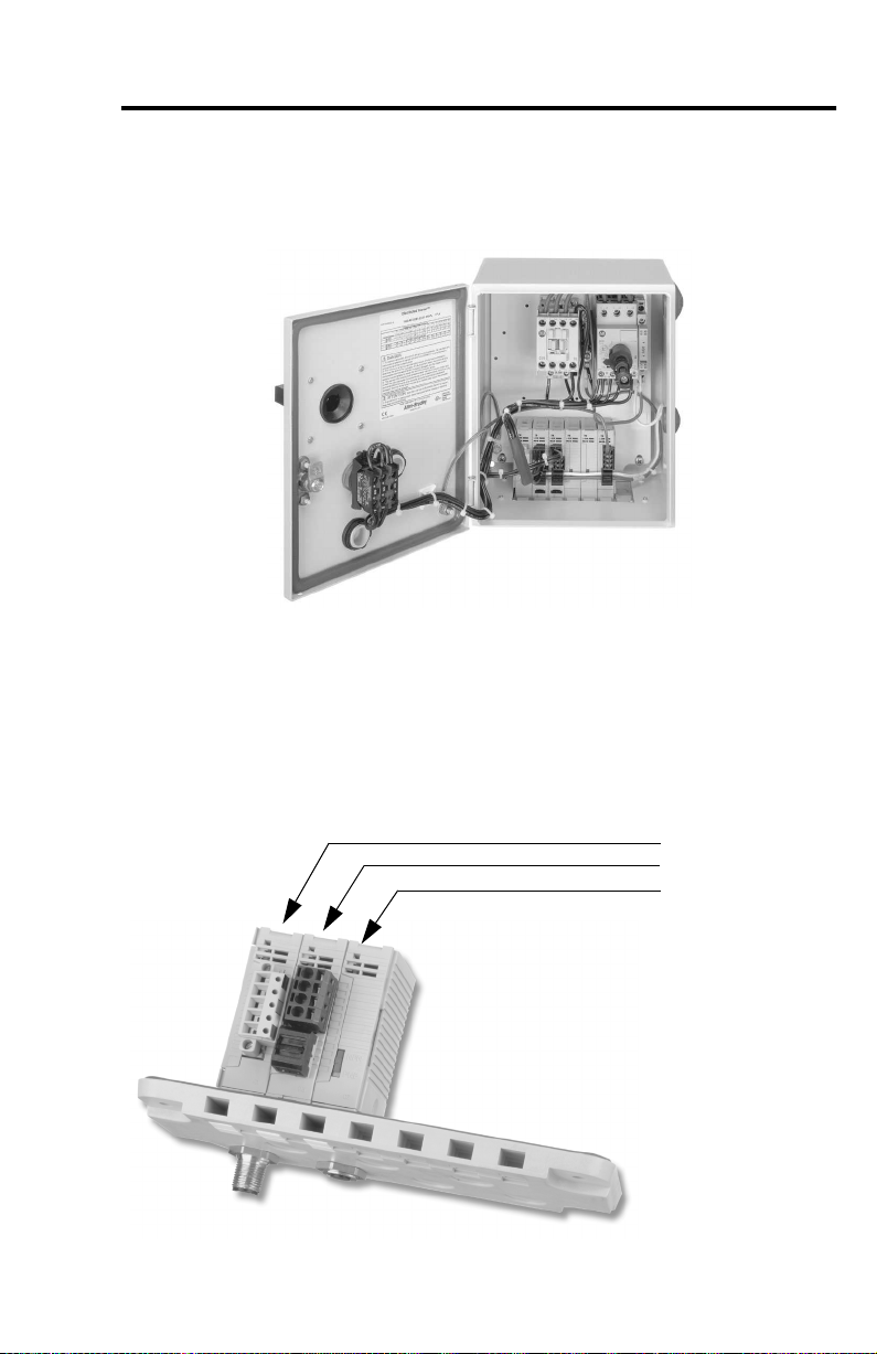
Figure 1.1 Typical Distributed Starter — Modular-DSA I/O System Modules
Mounted on a Gland Plate in an Enclosed Combination Motor Starter
The Modular DSA I/O System can be mounted traditionally on a DIN Rail or on a Gland
Plate to accrue benefits of wire simplification.
The Modular DSA I/O System mounted to a gland plate allows for easy connection from
outside the enclosure for DeviceNet, standard sensors, and other auxiliary devices via M12
micro quick-disconnect connectors.
Figure 1.2 Modular DSA I/O System Mounted on a Gland Plate
'1*
,%;2:RUVLPLODU
,%6
Publication 198-UM001B-EN-P September 2001
Page 12
1-3 Product Overview
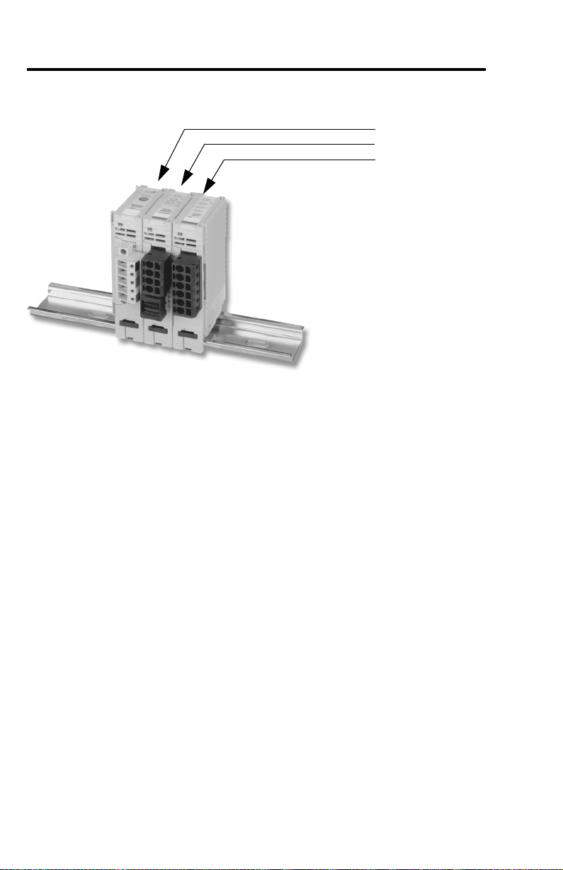
Figure 1.3 Modular-DSA I/O System Mounted on DIN Rail
'1
,%;2:RUVLPLODU
,%
The Modular-DSA I/O System provides specially designed modules that provide many
benefits in a distributed architecture. The Sensor Module (198-IB2S) is specifically designed
to interface standard photoelectric and proximity sensors from the area surrounding the
enclosure. Since the connection for standard sensors is available outside the enclosure via an
M12 connector, and power is sourced from DeviceNet, no additional wiring is necessary.
The Starter Modules (198-IA2XOW1, 198-IB2XOB1, and 198-IB2XOW1) are designed to
provide a fast, effective way to control and gather the basic information from either a DC
operated or an AC operated starter.
The connections to specific 190D/191D Compact Combination Starters are made via cable
harnesses, such as Cat. No. 198-MSACBL6. Additionally, the 198-IB2XOW1 module sources
input power from DeviceNet. This allows many applications to turn off control power and
still be able to read the inputs for diagnostics.
Publication 198-UM001B-EN-P September 2001
Page 13
Product Overview 1-4
Cat. Nos.
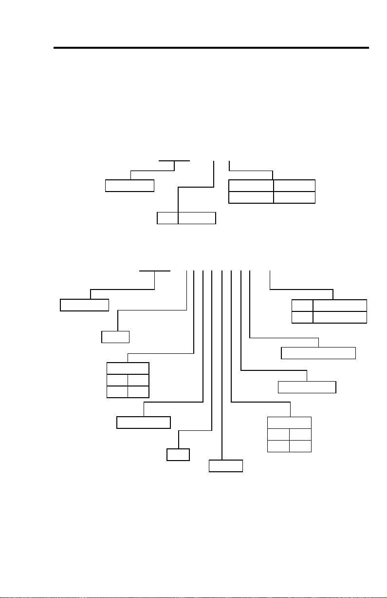
The catalog numbering scheme for the Modular-DSA I/O System is explained in Figure 1.4
and Figure 1.5 below. Note that all cat. nos. begin with 198, which stands for Bulletin 198
Modular-DSA I/O System.
Figure 1.4 Modular DSA — DeviceNet Cat. No.
198 – DNG
Bulletin No.
DN DeviceNet
GGland Plate
No Selection DIN Mount
Figure 1.5 Modular-DSA I/O System — I/O Module Cat. No.
198 – IB2XOB2S-Q5
Bulletin No.
Input
Input Type
AAC
BDC
No. of Inputs
AND
Output
Output Type
W Relay
BDC
Q5 M12 1-Key 5-Pin
G4 1/2" 2-Key 4-Pin
DeviceNet Sourced
No. of Outputs
DeviceNet Compatibility
The Modular-DSA I/O System communicates as a Group 2 slave device via DeviceNet
Protocol. It supports the Explicit, Polled I/O, and Change of State (COS) I/O messaging of
the predefined master/slave connection set and two additional explicit connections available
through Group 1 or Group 3.
Publication 198-UM001B-EN-P September 2001
Page 14

Chapter
2
Installation
Chapter Objectives
This chapter contains information about:
• Device storage and operating environment
• Mounting
• Connecting and wiring
Storage and Operation
To prolong the product life, take the following precautions:
• Store within an ambient temperature range of –40…+85°C (–40…+185°F).
• Store within a relative humidity range of 0…95%, non-condensing.
• Avoid storing or operating the device where it could be exposed to a corrosive
atmosphere.
• Protect from moisture and direct sunlight.
• Operate at an ambient temperature range of –25…+60°C (–4…+140°F). The
Modular-DSA I/O System enclosure is suitable for an ambient of –25…+40°C.
Modular-DSA I/O System is suitable for use in an industrial environment when installed in
accordance with these instructions. Specifically, this equipment is intended for use in a clean,
dry environment (Pollution Degree 2
Pollution Degree 2 is an environmentally where, normally, only non-conductive pollution occurs except
➊
occasionally a temporary conductivity caused by condensation shall be expected.
Pollution Degree 2 is an International Electrotechnical Commission (IEC) designations.
➋
➊) ➋.
Publication 198-UM001B-EN-P September 2001
Page 15

Electrostatic Discharge
Installation 2-2
IMPORTANT
Remove Power
IMPORTANT
Electrostatic discharge can damage integrated circuits or
semiconductors if you touch bus connector pins. Follow these
guidelines when you handle the module.
• Touch a grounded object to discharge static potential.
• Do not touch the bus connector or connector pins.
• Do not touch circuit components inside the module.
Remove power before removing or inserting a module in the I/O
line-up. When you remove or insert a module with power applied, an
electrical arc may occur. An electrical arc can cause personal injury or
property damage by:
• Sending an erroneous signal to your system’s field devices
• Causing damage to the product
Electrical arcing causes excessive wear on module contacts Worn
contacts may create electrical resistance.
Publication 198-UM001B-EN-P September 2001
Page 16
2-3 Installation
Approximate Dimensions
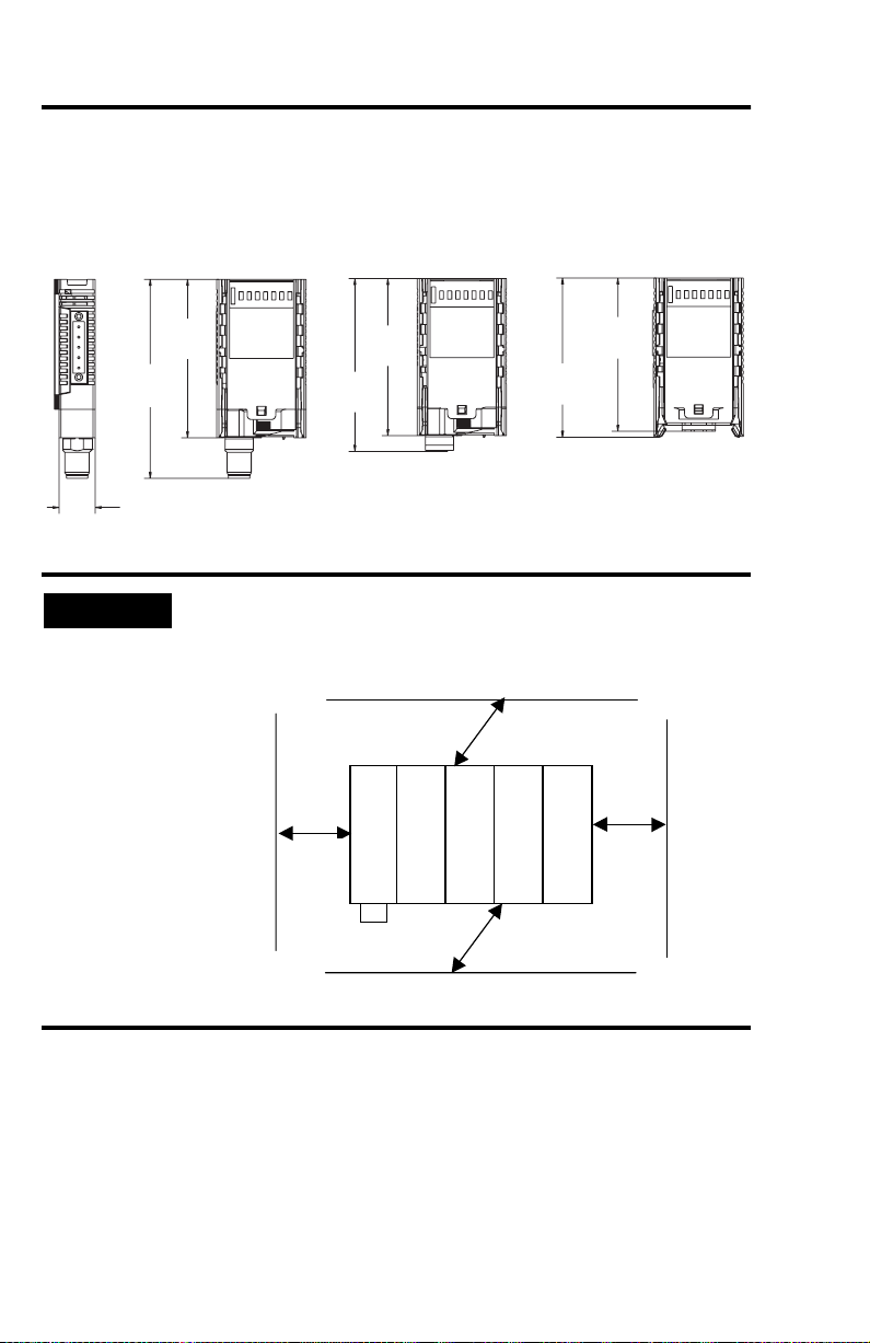
Dimensions are in millimeters (inches).
Figure 2.1 DIN Module Mounting Dimensions
98
(3-27/32)
18
(11/16)
IMPORTANT
78
(3-1/16)
(3-1/16)
85
(3-11/32)
77
(3-3/32)
76
(2-31/32)
78
Maintain spacing from enclosure walls, wireways, adjacent equipment,
etc. Allow 25 mm (1 in.) of space on all sides for adequate ventilation,
as shown:
Vent Side
25mm (1 in)
Vent
Side
End
25mm
(1 in)
Mod-DSA I/O
End
End
25mm
(1 in)
DeviceNet
Mod-DSA I/O
25mm (1 in)
Connector Side
Mod-DSA I/O
Mod-DSA I/O
Connector
Side
End
Publication 198-UM001B-EN-P September 2001
Page 17
Module Installation
The I/O System can be mounted either on a DIN Rail or a Gland Plate.
Installation 2-4
IMPORTANT
During gland plate or DIN Rail mounting of all devices, be sure that
debris (metal chips, wire strands, etc.) do not fall into the module. Such
debris could cause damage on power-up.
IMPORTANT
When attaching I/O modules, it is very important that the modules
are fully seated on either the DIN Rail or the gland plate. This ensures
that the module-to-module connectors are properly mated and that
the modules are properly grounded.
DIN Rail Mounting
The Modular-DSA I/O System modules can be mounted using either the 35 x 7.5 mm
(EN 50 022-35 x 7.5) or 35 x 15 mm (EN 50 022-35 x 15) DIN Rail.
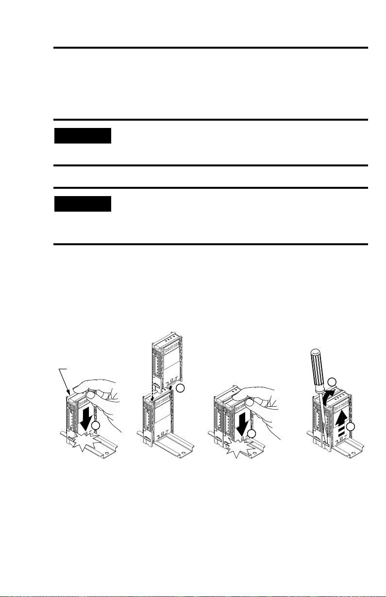
Figure 2.2 DIN Rail Mounting and Removal
198-DN
2
1
Click
1
3
Click
2
Publication 198-UM001B-EN-P September 2001
Page 18
2-5 Installation
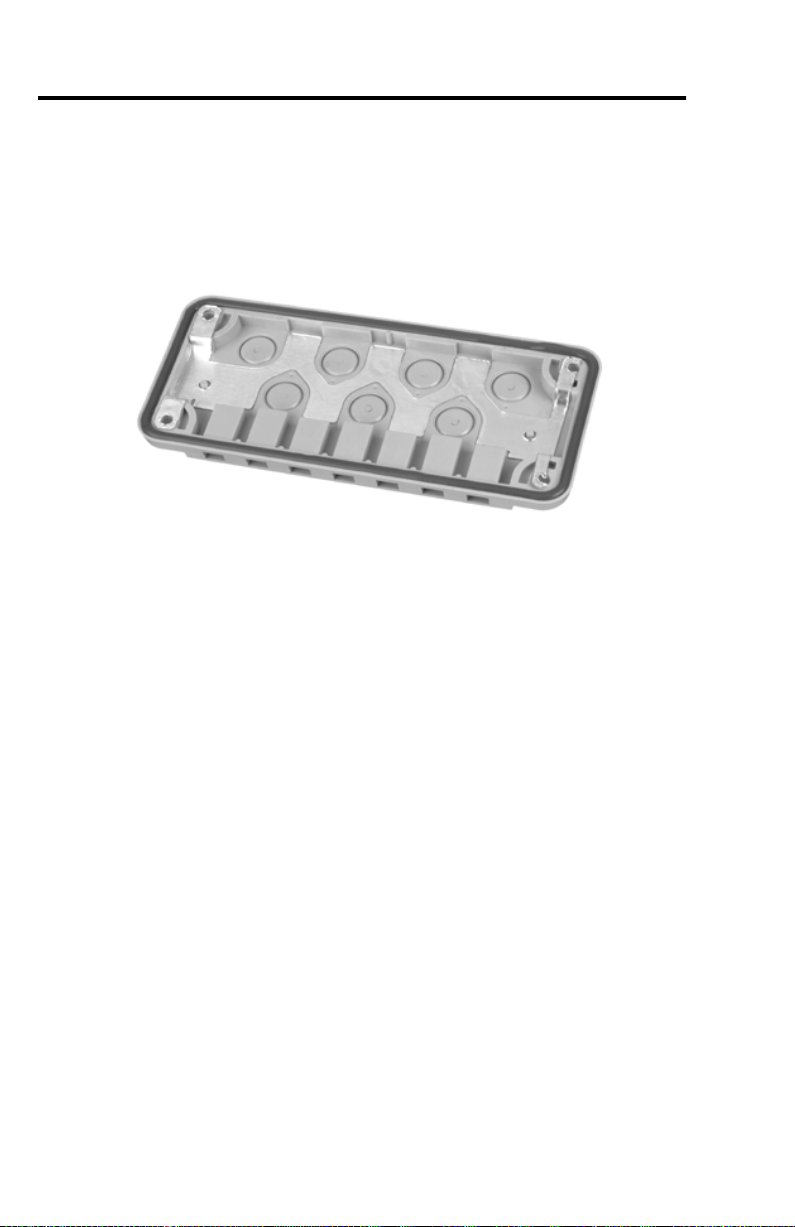
Gland Plate Mounting
Gland plates may also be referred to as cable plates. These plates are designed to cover
rectangular holes in standard enclosures, and to allow easy power and signal access to the
enclosure.
Figure 2.3 Plastic Gland Plate
Refer to Chapter 5 for a complete list of gland plate specifications.
Publication 198-UM001B-EN-P September 2001
Page 19
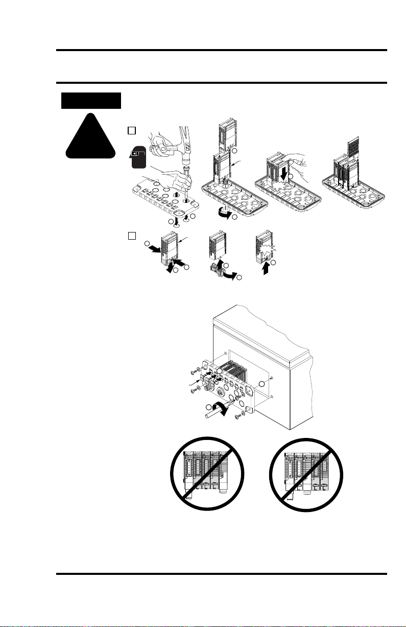
Installation 2-6
ATTENTION
!
The gland plate must be on a flat secure surface and safety glasses
must be worn when opening the knockouts.
1
4
198-DNG
5
Click
1
2
2
1
198-IB2S
198-OW2S
198-DNG
1
2
Installation of Gland Plate and Modular-DSA I/O System in Enclosure
1492-SM8X9
1.12 - 1.35 N-m
(10 - 12 lb-in)
3
Click
4
3
3
5
1
2
2.25 - 2.8 N-m
(20 - 25 lb-in)
• No more than two DIN Modules between Gland Modules
• No more than one DIN Module to the right of the Gland Module
• Consult Allen-Bradley for information on exceeding these
specifications
Publication 198-UM001B-EN-P September 2001
Page 20
2-7 Installation
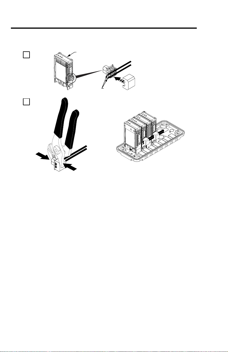
Figure 2.4 Physical Diagram of Connecting Control Power to I/O Modules
1
198-IA2XOW1
198-IB2XOB1
198-IB2XOW1
198-OW2S
.324 - 2.08 mm
22 - 14 AWG
2
2
Wiring Diagrams
Refer to appropriate module in Chapter 5 for wiring information.
Publication 198-UM001B-EN-P September 2001
Page 21

Chapter
3
Operation
Chapter Objectives
This chapter contains the following information:
• Configuring the Modular DSA I/O System
• DeviceNet Explicit Messaging
• MOD/Net Status LED
• I/O Status LED
Basic Configuration
This section will provide the user with the basic steps of bringing up a device, such as the
MDSA, on DeviceNet. This section will assume that the user has RSNetworx and a
Cat. No. 1770-KFD module.
The first step to setting up a system is to power up the device. Once the DeviceNet module is
powered up it will attempt to determine the network baud rate of the other devices on the
network. After determining the network baud rate, it will set its baud rate to the same baud.
While the module is determining the baud rate of the network, the MOD/NET Status LED
will blink green for 1/4 second, red for 1/4 second, and then turn off.
IMPORTANT
Once the proper baud rate is set, the MOD/NET LED will either blink green or turn solid
green if a connection is established between it and another device. If the LED turns solid red,
it has failed the duplicate MAC ID check. The above sequence is done when the Autobuad
rate is enabled. This sequence can be disabled to allow a baud rate to be manually configured
(see Advanced Topics, page 3-14).
Once the unit has determined the baud rate of the network, the MOD/NET Status LED will
be solid green, indicating that the device is on-line and operating in a normal condition. The
I/O Status LED will be solid red, indicating that the configuration of the I/O modules has
not been accepted.
Publication 198-UM001B-EN-P September 2001
If there is no traffic on the network, the device will not be able to
determine a network baud rate. The MOD/NET Status LED will
continue to execute the above sequence until network traffic is detected.
Page 22
3-2
To begin the configuration of DeviceNet, execute the RSNetworx software and complete the
following procedure.
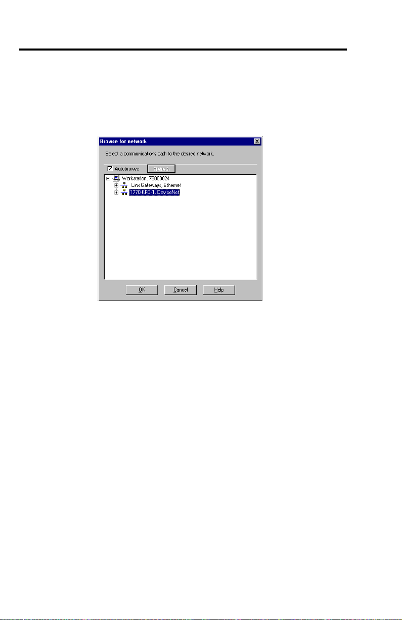
1. From the 1HWZRUN menu, choose 2QOLQH. After “online” has been selected you will
see the following screen:
2. From the options shown on the above screen, choose the appropriate PC interface
and click OK. RSNetworx will tell the user to upload or download devices before
viewing configuration.
3. Select the OK button. RSNetworx will now browse the network and display all of the
nodes it has detected on the network.
Publication 198-UM001B-EN-P September 2001
Page 23
3-3
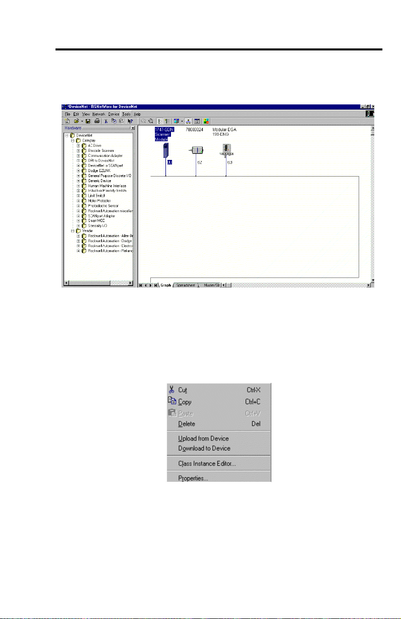
RSNetworx will display an icon and the name and node address of each device on the
network. The figure below shows the RSNetworx window after the browse of the network.
If the name of the device shows up as “Unrecognized Device” it means that the device is not
registered. (see Advanced Topics, page 3-14).
The user is now able to configure the communications between the I/O modules. To begin
the configuration of the communications between the I/O modules follow the steps below.
1. Select and right click the Modular DSA 198-DNG icon. The following list of options
should appear.
Publication 198-UM001B-EN-P September 2001
Page 24
3-4
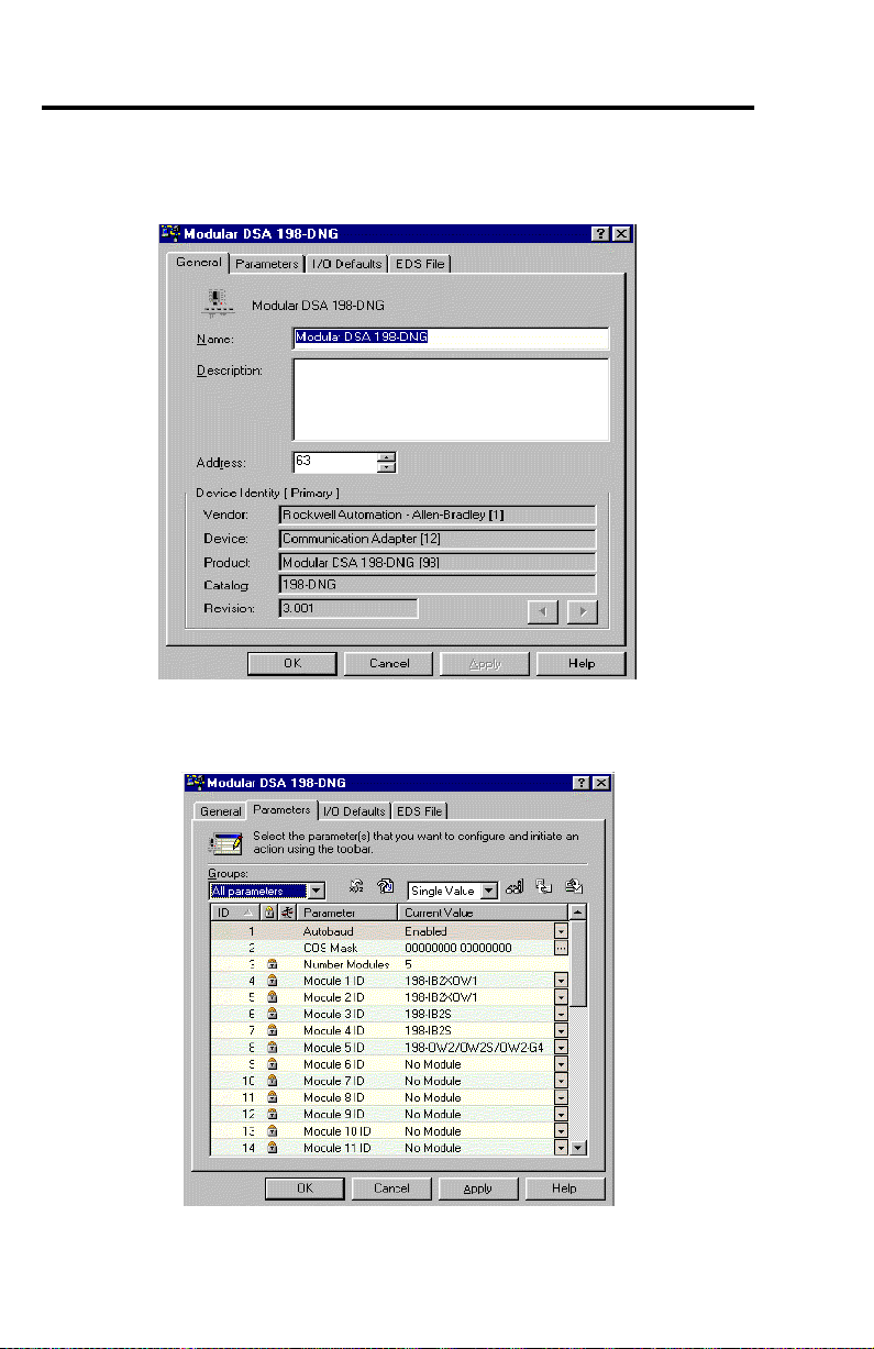
2. Select SURSHUWLHV. RSNetworx will verify the identity of the device and then the
following screen will appear:
3. Select the “Parameter” tab. RSNetworx will then prompt the user to upload the
parameters from the device. Select the 8SORDGbutton. The following screen appears:
Publication 198-UM001B-EN-P September 2001
Page 25

3-5
4. From the screen shown, verify that the number of modules and the name of the
modules recognized are correct. Select the Accept Config.parameter (parameter 3 or
35). Double click the value of that parameter. A drop-down list of options will appear.
Select the “Accept config.” option.
5. Select the Apply button. RSNetworx will ask the user whether it should download the
changes to the device. Select yes. The Device will recycle power and the I/O status
LED will no longer be red. The MOD/NET status LED will be flashing green,
indicating that the device is properly connected to the network and is waiting to
establish connections to other nodes.
DeviceNet MAC ID(node address)
The DeviceNet node address may be set to a value from 0…63. Note that, in most
DeviceNet systems, node address 0 is usually reserved for the master device. Node address
63 is generally the factory default for slave devices. The node addresses can be changed in
three different ways. The first two ways listed below are accomplished using the software
setting, while the third one is done by setting hardware switches that reside on the 198-DN or
-DNG module.
IMPORTANT
1. The first manner of changing the node address is accomplished by double clicking on
the existing node number. The user will then be able to erase the existing node
number and enter the desired node number. Once the desired node number has been
entered, deselect the device and the following screen will appear:
2. From the above screen select the <HVbutton and the node number will be changed.
The MDSA must be offline before performing the following procedure.
Publication 198-UM001B-EN-P September 2001
Page 26
3-6
The second way of changing a node address can be done by following the steps shown below.
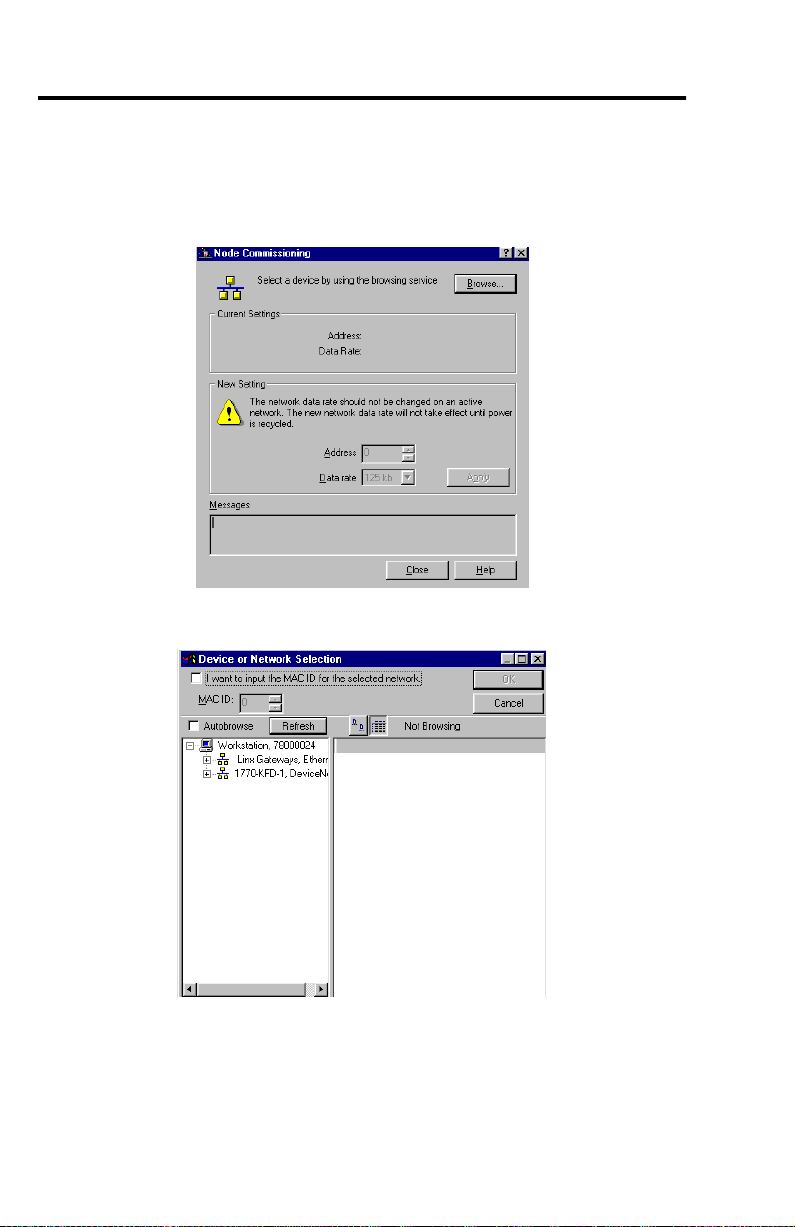
1. From the 7R ROV menu, choose 1RGH&RPPLVVVLRQLQJ« The following screen will
appear:
2. Click the %URZVH button to upload the network. The following screen will appear:
Publication 198-UM001B-EN-P September 2001
Page 27
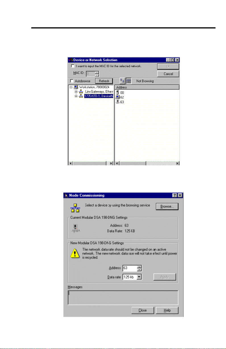
3-7
3. From this screen select the appropriate PC interface. For our example we will use the
1770-KFD-1. After the appropriate interface is chosen the following screen appears:
4. Select the MDSA device and press the 2. button. After RSNetworx has finished
updating the network the following screen will appear:
Publication 198-UM001B-EN-P September 2001
Page 28
3-8
5. Choose the desired node address and click the $SSO\button. Click the ([LW button.
The unit will then reset.
6. Re-browse the network to establish a connection with the new address.
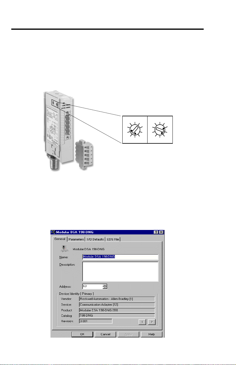
The final way to set the unit’s node address is by directly setting the node address switches
found on the DeviceNet Control Module. The factory-default setting is still node address 63.
Node Address
0
8
6
MSB
Address 63 Shown
0
2
8
4
2
4
6
LSB
DeviceNet Module Configuration Parameters
The following parameters are defined in the EDS files and appear in a Device Parameter tab
of the RSNetworx. To invoke a Device Parameter window:
1. Double-click on the device. The following window will appear:
Publication 198-UM001B-EN-P September 2001
Page 29
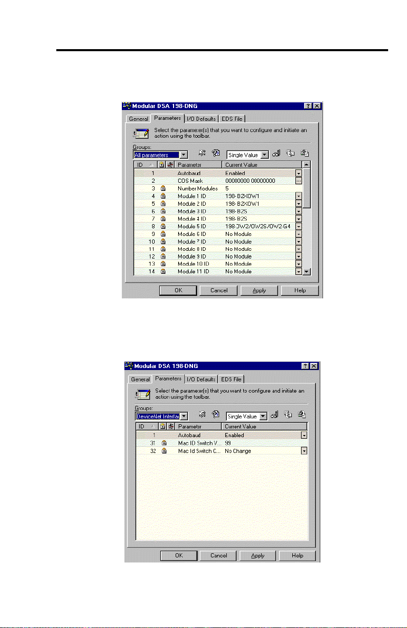
2. Select the Parameter tab. RSNetworx will then ask you to upload the parameters from
the device. Select the 8SORDG button, and the following screen will appear:
Autobaud
3-9
In the Groups field select the DeviceNet Interface group. The following screen will appear:
Publication 198-UM001B-EN-P September 2001
Page 30
3-10
3. To change the settings of a parameter, click the pull down tab on the desired
parameter. For example, when you click the pull down tab on the $XWREDXG
parameter, you will see a list box with available choices for this parameter. After
choosing the desired setting,click the $SSO\ button. You will then be asked to
download the configuration to the device; select the \HV button.
ATTENTION
Injury or damage may occur when parameters are not set according to
the application requirements.
!
When this parameter has the value (QDEOH, the Modular DSA DeviceNet module will
attempt to match the network baud rate at power-up. When this parameter has the value
'LVDEOHG, the power-up autobaud feature is disabled. When the Autobaud parameter is
changed, the new value will be applied when the power is cycled after saving to the device.
(The Autobaud screens are shown above.)
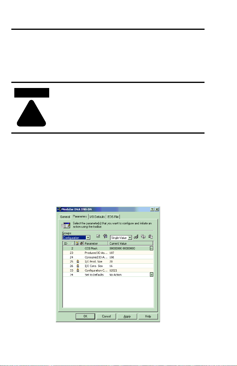
Choosing an I/O Assembly Format
In the Groups field, select the “Configuration” group. The following screen will appear:
Refer to Appendix A to determine which I/O assembly data format to select. The different
I/O assembly formats allow flexibility for different systems. Assemblies 100 and 101 are
Publication 198-UM001B-EN-P September 2001
Page 31

3-11
optimized for minimum length and will have variable length dependent upon the number of
modules. Assemblies 102 and 103 give a more user-friendly format by using one byte per
module. They also has a length that varies by the number of modules. Assemblies 104 and 105
are the default for the 198-DNG units. These assemblies have a fixed length and support a
maximum of six I/O modules. The status information in Assembly 105 has been condensed
for six modules. Assemblies 106 and 107 are the default assemblies for the 198-DN unit.
These assemblies have a fixed length and support up to 16 modules.
The Modular DSA can not be mapped into a scan list when changing these parameters or the
unit will respond with the error message Object State Conflict.
After the assemblies have been chosen and downloaded to the device, select $OO and 8SORDG
IURP'HYLFH. This will update the I/O Prod. Size and I/O Cons. Size. Record these values to
be used later during the I/O Mapping.
Mapping to the Scanner
To map the Modular DSA in the scanlist of a scanner, double-click on the scanner icon in
RSNetworx for DeviceNet. The following screen will appear.
1. Select the Scanlist tab. After selecting the Scanlist tab the user will be asked to upload
the configuration to the device. Press the Upload button to allow RSNetworx to
upload the scanlist from the scanner.
Publication 198-UM001B-EN-P September 2001
Page 32

3-12
2. When the uploading is completed the following screen will appear:
3. There is a list that contains all of the available devices in the scanlist screen. Highlight
the device that is to be mapped. For our purposes we will select the MDSA from the
Available Devices box and press the “>” button. After RSNetworx updates the changes,
the MDSA device should appear in the Scanlist box.
Publication 198-UM001B-EN-P September 2001
Page 33

3-13
4. Once the MDSA appears in the Scan list box, Select the Download to Scanner button.
The following screen will appear:
5. Select Selected Scanlist Records to select records that refer to the device that is
highlighted, (in this case, the MDSA). After selecting the Selected Scanlist Records , click
the 'RZQORDG button. After RSNetworx is finished downloading to the scanner,
press the $SSO\ button. The user will be prompted to download the changes to the
device. Select \HV to allow changes to download. Then select 2..
IMPORTANT
Parameters can not be changed once a device has been added to the
scanlist.
Publication 198-UM001B-EN-P September 2001
Page 34

3-14
Advanced Topics
Registering New Devices
A new device appears on the RSNetworx screen as “Unrecognized Device”. This means that
RSNetworx has not yet registered the device. If a device is not registered there will not be a
EDS file for that device.
Electronic Data Sheet(EDS) files are specifically formatted ASCII files that provide all of the
information necessary for a configuration tool, such as RSNetworx, to access and alter the
parameters of a device. Information about each parameter, such as parameter minimum,
maximum, and default values and parameter names and units is contained in the EDS file.
There are specific EDS files that describe all of the parameters of the DeviceNet module. The
DeviceNet module uses vendor codes, device type and product codes to identify which EDS
file to use for the Modular DSA DeviceNet Module. Table 3.1 below gives the structure for
the Modular DSA DeviceNet module EDS file.
Device Type Product Code Cat. No. EDS File Name
12 Adapter 67
12 Adapter 98
198-DN Eds\1.vnd\12.typ\67.cod\1.eds
198-DNG Eds\1.vnd\12.typ\98.cod\1.eds
IMPORTANT
Publication 198-UM001B-EN-P September 2001
The EDS files are included with RSNetworx version 2.51 and above. If
you are working with an older version or with other tools, please visit
http://www.ab.com/networks/eds for a copy of the files.
Page 35

3-15
To register a device you must first obtain the EDS file from the above web page. After
obtaining the files do the following:
1. From the 7R ROV menu, choose ('6:L]DUG and click on the 1H[W button. The
following screen will appear:
2. From the above screen select the 5HJLVWHUDQ('6ILOHV and click 1H[W button.
Publication 198-UM001B-EN-P September 2001
Page 36

3-16
3. The Registration screen(shown below) should appear. In this screen select 5HJLVWHUD
LQJOHILOH. (If you are registering more than one file you can select the 5HJLVWHUD
V
G
LUHFWRU\RI('6ILOHV)
4. Now choose the %URZVH button and select the appropriate EDS file to be registered.
Click the 1H[W button. The following screen appears:
3
Publication 198-UM001B-EN-P September 2001
Page 37

5. Click the 1H[Wbutton. The following screen appears:
3
6. Click the 1H[Wbutton. The following screen appears:
3-17
Publication 198-UM001B-EN-P September 2001
Page 38

3-18
7. Click the 1H[Wbutton. The following screen appears:
8. Click the )LQLVK button. After a short while RSNetworx will update your online
screen by replacing the Unrecognized Device with the name given by the EDS file
you have just registered.
Publication 198-UM001B-EN-P September 2001
Page 39

3-19
COS Mask Parameter
Double-click on the Modular DSA device to get to the device parameters menu, which was
described in the previous section.(DeviceNet Module Configuration parameters)
1. In Groups select the Configuration group; you will see the following screen:
2. To change the settings of the COS Mask Parameter, click the pull-down tab on the
parameter. The following screen will appear:
Publication 198-UM001B-EN-P September 2001
Page 40

3-20
This parameter is used to configure the behavior of the COS connection. If you will be using
the COS connection to produce the input data, you may want to disable a particular input
module from causing a COS production of data. By checking the bit location of the module,
you will not allow a change in input data from this module to trigger the COS data
production. Bit 0 refers to the I/O module located in slot 1. If an output only module is
check, it will create a value out of range error when the Apply button is clicked.
3. Once you have made your changes, click the Apply button. You will be asked to
download the configuration to the device. Select yes and click the OK button.
I/O Module Configuration Parameters
The Modular DSA I/O modules contain several configuration parameters. There are three
types of I/O objects that are implemented in the I/O modules. They are the discrete input
point, which has on-off delays and off-on delays that are configurable per point; the discrete
output point, which has fault state, fault value, idle state, and idle values that are configurable
per point; and the presence sensing object, which has an operating mode that is configurable
per sensing point. Below are tables that contain the configuration parameters for the three
I/O objects.
Table 3.A Discrete Input Point Object
Class ID Instance ID Attribute IDAccess
8 1, 2, 3, or 4 3 Get Value BOOL Input point Value
8 1, 2, 3, or 4 5 Get/Set OFF_ON
8 1, 2, 3, or 4 6 Get/Set ON_OFF
Rule
Name Data Type Value
0 = Off
1 = On
Delay
Delay
UINT 0
UINT 0
s
µ
2000 µs
4000
8000 µs
16000 µs
s
µ
2000
4000 µs
8000 µs
16000
Publication 198-UM001B-EN-P September 2001
s
µ
s
µ
s
µ
Page 41

Table 3.B Discrete Output Point Object
3-21
Class ID Instance IDAttribute IDAccess
Rule
9 1 or 2 3 Get/Set Valu e BOOL 0 = Off
9 1 or 2 5 Get/Set Fault
9 1 or 2 6 Get/Set Fault
9 1 or 2 7 Get/Set Idle
9 1 or 2 8 Get/Set Idle
Name Data Type Value
1 = On
Action
Valu e
Action
Valu e
BOOL 0 = Go to Fault value
BOOL 0 = Off
BOOL 0 = Got to Idle State
BOOL 0 = Off
1 = Hold Lasts State
1 = On
1 = Hold Last State
1 = On
Table 3.C Presence Sensing Object
Class ID Instance IDAttribute IDAccess
Rule
14 1 or 2 1 Get Output BOOL 0 = No signal present
14 1 or 2 8 Get/Set Operate
14 1 or 2 122 Get Open BOOL 0 = No open condition
14 1 or 2 123 Get Short BOOL 0 = No short condition
Since this information is dynamically established during the power-up sequence, these
parameters can not be accessed through the standard EDS. There are two basic steps to set
these parameters. First, map your particular configuration of modules, then use the &ODVV
,QVWDQFH(GLWRU under the 'HYLFH menu.
Name Data Type Value
1 = Signal present
Mode
BOOL 0 = Output attribute as specified
1 = Output Attribute inverted
1 = Open condition detected
1 = Short condition detected
1. To begin configuring the parameters, you must determine the instance number of the
I/O points for your particular configuration. The instance number for any system
begins counting from the left to the right. An example of determining instance
numbers is found below.
Publication 198-UM001B-EN-P September 2001
Page 42

3-22
EXAMPLE
Figure 3.1 Lineup
Mod 0 Mod 1 Mod 2 Mod 3 Mod 4 Mod 5 Mod 6
Mod/Net Out 1 In 1 In 1 In 1 In 1 In 1
I/O Out 2 In 2 In 2 In 2 In 2 In 2
In 3 Out 1 Out 1
In 4
Cat. No.
198-DN
Cat. No.
198-OW2
Cat. No.
198-IB4
Cat. Nos.
198-IA2X,
198-OW1
Cat. Nos.
198-IB2X,
198-OB1
Cat. Nos.
198-IA2
Cat. No.
198-IB2S
In the above example you can see that the first module from the left is the DeviceNet
Module. The DeviceNet Module doesn’t have any instances. The next module is Mod1. It
contains the first output (Out 1) and second output (Out2), which are recognized as
output instance 1 and output instance 2, respectively. Input In1 on Mod2 is the first input
seen from the left, therefore it becomes input instance 1. Similarly In2 of Mod3 is the sixth
input seen from the left, therefore it becomes input instance 6. The other instances in this
system is done in a similar fashion and can be found in the table below, followed by a blank
table for you to record your line-up.
Table 3.D Instance Table
Module
Description
Mod.
Mod.
Slot
Ty pe
0 DNet — — — — — — — —
1 2 Output — — — — 1 2 — —
2 4 DC Input 1 2 3 4 — — — —
3 AC Starter 5 6 — — 3 — — —
4 DC Starter 7 8 — — 4 — — —
5 2 AC Input 9 10 — — — — — —
6 Sensor — — — — — — 1 2
7…16 Module — — — — — — — —
Input Instances Output Instances Presence Sensing
In 1 In 2 In 3 In 4 Out 1 Out 2 Sensor 1
Instances
(In 1)
Sensor 2
(In 2)
Publication 198-UM001B-EN-P September 2001
Page 43

Table 3.E Blank Table
3-23
Module
Description
Mod.
Mod.
Slot
Ty pe
0 DNet
1
2
3
4
5
6
7…16
8
9
10
11
12
13
14
15
16
Input Instances Output Instances Presence Sensing
In 1 In 2 In 3 In 4 Out 1 Out 2 Sensor 1
Instances
(In 1)
Sensor 2
(In 2)
Now that you have obtained the instance numbers for your system, you can begin
configuration by using the Class Instance Editor under the Device menu. You will be
prompted with a warning message. Please read carefully and select the “I agree” button.
Configuration for every system will vary depending on the needs of the user. Below are some
examples for the configuration of the above lineup.
Publication 198-UM001B-EN-P September 2001
Page 44

3-24
EXAMPLE
The following example will set the Off to On Delay of Input 2 of the AC starter to
8msec(8000µsec) filter in the previous lineup (Figure 3.1).
For this example, we will use values from Appendix A and the above Instance table.
Class = 8
Instance = 6
Attribute = 5
These values will be entered in their proper fields seen in the following diagram.
IMPORTANT
In the above screen, be sure that the “Data Size” option is set to “Word(2bytes)”. Data
sent to the device should be “8000” and the “value in decimal” option should be selected.
Change the description to “Set Single Attribute”, because you are setting a value and not
getting a value.
After making the desired changes press the ([HFXWH button to set the configuration. The
message “Execution was completed” should appear in the “Data received for device”
Values in the fields should be in hex.
Publication 198-UM001B-EN-P September 2001
Page 45

3-25
window. This procedure can be repeated for all of the input points for both of the Off to
On delay and On to Off delay.
IMPORTANT
EXAMPLE
The following example will set the Idle Action of output 1 of the DC Starter to Hold Last
State. See the lineup established in Figure 3.1.
The same steps as the above example will be taken to obtain the values of the Class,
Instance, and Attributes for the following:
The MDSA cannot be mapped to the scanlist while using the Class
Instance editor. There will be a communication error displayed if you
execute an instruction.
In the above screen, “Data sent” should be “1”. The “values in decimal” option should be
checked.
Make the desired changes. In this example, to set the Idle Action of Output 1 of the Dc
Starter to Hold Last State, click the ([HFXWH button. This procedure can be repeated for
all of the output points for Fault Action, Fault Value, Idle Action, and Idle Value.
Publication 198-UM001B-EN-P September 2001
Page 46

3-26
EXAMPLE
The following example will set the Operate Mode of input 1 of the Sensor module to
Invert the signal before transmitting it on DeviceNet. See the lineup established in Figure
3.1.
Once again we will use the same steps as in the above example to obtain the values of the
Class, Instance, and Attributes for the following
In the above screen, “Data sent” should be “1”.
Make the desired changes. In this example, to set the Operate Mode of input 1 of the
Sensor to Invert before transmitting, click the ([HFXWH button. This procedure can be
repeated for all of the presence sensing instances.
DeviceNet Explicit Messaging
The above configuration of the I/O module parameters is an example of explicit messaging.
DeviceNet Explicit Messages are generally used to configure a DeviceNet device.
Configuration tools such as the “DeviceNet Manager” or “RSNetworx” use explicit messages
when communicating with a device. Some tools, such as Rockwell Software’s “RSServer for
DeviceNet” use explicit messages to help build custom DeviceNet system user interfaces for
a PC. When using such a tool, it is often useful to be able to control the outputs of the
Modular DSA system and also read the status information and the inputs of the
Publication 198-UM001B-EN-P September 2001
Page 47

3-27
Modular DSA system using explicit messaging. Explicit messages contain the following
information:
• Service – Tells the device what action to take in response to the message. Service
reads information from a device and for writes information to a device.
• Class – Tells the device which object class to send the service to. Classes are
identified by their numeric “class code”. Appendix A contains a complete list of the
classes that are implemented in the Modular DSA system.
• Instance – Each object class can contain one or more “instances” of that class in a
given device. Instances are numbered starting with instance 1. The value ”0” refers to
the class itself, not any individual instance of that class. Appendix A contains a
complete list of instances that are implemented for each class in the Modular DSA
system.
• Attribute – An attribute is a single piece of information related to an object class or
instance. Attributes are numbered starting at attribute number 1. Note that attributes
need to be numbered sequentially. Appendix A contains a complete list of attributes
for each class and instances implemented in the Modular DSA system.
All attributes can be read using the ”Get Single Attribute” service to that particular attribute.
Some attributes can be written to using the “Set Single Attribute” service to that particular
attribute. There are a few special rules to keep in mind when trying to control an output with
explicit messaging.
• An output cannot be controlled (Set Single Attribute service) via explicit messing if a
DeviceNet I/O connection exists. For example, if a DeviceNet scanner has control of
a Modular DSA system, then an explicit message attempting to control an output will
result in the Modular DSA returning an error response of “Object State Conflict”,and
the output will not change state.
• An output cannot be controlled via explicit messaging unless the explicit connection
has a non-zero Expected Packet Rate. (See DeviceNet Spec. Vol1 for details on the
explicit message connection.)
• If the explicit connection is released/closed, all outputs that this connection has
controlled will go to the IDLE STATE.
• If the explicit connection times out, outputs that this connection has controlled will
go to the FAULTED STATE.
DeviceNet I/O Messaging
DeviceNet I/O messages are used by Allen-Bradley DeviceNet scanners to turn on the
Modular DSA outputs, to read the status of the I/O system inputs, and also to read the status
fault information for the system. The size and format of the DevicNet I/O messages is
determined at power-up. After determining what type of modules are attached and whether
they are in the same configuration as that stored in the EEprom, the scanner will build I/O
messages.
Publication 198-UM001B-EN-P September 2001
Page 48

3-28
Each I/O module contains 4 bits (one nibble) of data. The data is packed into two modules
to a single byte of data. The Input instance (produced data) contains five bytes of status and
fault information followed by the input data for each module containing inputs. The Output
instance (consumed data) contains the output data for each module containing outputs.
IMPORTANT
The size of the I/O produced data and I/O consumed data can be read
from the parameters located in the Configuration Group of the
Device Parameter tab.
The device can produce data when one of its inputs changes state. This is how the device
produces data when a Change of State (COS) connection is allocated. The device also
produces data in response to an I/O message from its master. This how the device produces
data when a Polled I/O connection is allocated. Following is an example of how the I/O
messages are formatted for the lineup shown.
Figure 3.2 Lineup
Cat. No.
198-DNG
Mod 0 Mod 1 Mod 2 Mod 3 Mod 4 Mod 5 Mod 6
Mod/Net Out 1 In 1 In 1 In 1 In 1 In 1
I/O Out 2 In 2 In 2 In 2 In 2 In 2
Cat. No.
198-OW2
Cat. No.
198-IB4
In 3 Out 1 Out 1
In 4
Cat. Nos.
198-IA2X,
198-OW1
Cat. Nos.
198-IB2X,
198-OB1
Cat. Nos.
198-IA2
Cat. No.
198-IB2S
Table 3.F I/O Module Data
Module I/O Bit Bit 1 Bit 2 Bit 0
2 Output Module Output X X Out 2 Out 1
4 DC Input Module Input In 4 In 3 In 2 In 1
AC Starter Module Input X X In 2 In 1
Output X X X Out 1
DC Starter Module Input X X In 2 In 1
Output X X X Out 1
2 AC Input Input X X In 2 In 1
1 AC Input Input X X X In 1
Sensor Module Input Open Short In 2 In 1
X = Reserved
Publication 198-UM001B-EN-P September 2001
Page 49

3-29
Table 3.G Instance 104 Data Format for Output Assembly
Module Byte Bit 7 Bit 6 Bit 5 Bit 4 Bit 3 Bit 2 Bit 1 Bit 0
1 0 X X X X X X Output 2
Valu e
2 1 X X X X X X X X
3 2 X X X X X X X Output 1
4 3 X X X X X X X Output 1
5 4 X X X X X X X X
6 5 X X X X X X X X
Output 1
Valu e
Valu e
Valu e
X = Reserved
Table 3.H I/O Output Assembly Data Attribute Mapping
Data Component Name Class Instance
Name Number Name Number
Module 1 Output 1 Discrete output point 09hex 1 Valu e 3
Module 1 Output 2 Discrete output point 09hex 2 Valu e 3
Module 3 Output 1 Discrete output point 09hex 3 Valu e 3
Module 4 Output 1 Discrete output point 09hex 4 Valu e 3
Number
Attribute
Publication 198-UM001B-EN-P September 2001
Page 50

3-30
Table 3.I Instance 105 Data Format for Input Assembly
Module Byte Bit 7 Bit 6 Bit 5 Bit 4 Bit 3 Bit 2 Bit 1 Bit 0
0 Module
Error
Number 1
1 Error
Code 6
1 2 X X X X X X X X
2 3 X X X X Input 4
3 4 X X X X X X Input 2
4 5 X X X X X X Input 2
5 6 — — — — X X Input 2
6 7 — — — — Open Short Input 2
X = Reserved
Module
Error
Number 0
Error Code 5Error
I/O
Module
Status 6
Code 4
I/O
Module
Status 5
Error
Code 3
I/O
Module
Status 4
Error Code 2Error Code 1Error Code 0Module
Valu e
I/O
Module
Status 3
Input 3
Value
I/O Module
Status 2
Input 2
Valu e
Valu e
Valu e
Valu e
Valu e
I/O
Module
Status 1
Error
Number 2
Input 1
Valu e
Input 1
Valu e
Input 1
Valu e
Input 1
Valu e
Input 1
Valu e
Publication 198-UM001B-EN-P September 2001
Page 51

Table 3.J I/O Input Assembly Data Attribute Mapping
3-31
Data Component Name Class Instance
Name Number Name Number
I/O Status Word DeviceNet Interface OB4hex 1 I/O Module
Error Code DeviceNet Interface OB4hex 1 Error Code 25
Module Error Number DeviceNet Interface OB4hex 1 Module Error
Module 2 Input 1 DIP O8hex 1 Val ue 3
Module 2 Input 2 DIP O8hex 2 Val ue 3
Module 2 Input 3 DIP O8hex 3 Val ue 3
Module 2 Input 4 DIP O8hex 4 Val ue 3
Module 3 Input 1 DIP O8hex 5 Val ue 3
Module 3 Input 2 DIP O8hex 6 Val ue 3
Module 4 Input 1 DIP O8hex 7 Val ue 3
Module 4 Input 2 DIP O8hex 8 Val ue 3
Module 5 Input 1 DIP O8hex 9 Val ue 3
Module 5 Input 2 DIP O8hex 10 Value 3
Module 6 Input 1 DIP OEhex 1 Val ue 1
Module 6 Input 2 DIP OEhex 2 Val ue 1
Module 4 Open DIP OEhex 1 Val ue 122
Module 5 Short DIP OEhex 1 Va lue 123
Number
Attribute
22
Status
29
Number
Refer to Appendix A for a more detailed description of each attribute shown in the tables
above.
Mod/Net Status LED
The Module/Network Status LED is a bi-colored (red/green) LED that provides status
information on DeviceNet communications. Table 3.K summarizes the operation of the
LED.
Publication 198-UM001B-EN-P September 2001
Page 52

3-32
Table 3.K LED Operation
For this state: MS/NS LED is: To indicate:
Powerup and
Autobaud
Not Powered/Not
On-line/Device is
not on-line
Device Operational
AND On-line,
Connected
Device Operational
AND On-line, Not
Connected or
Device On-line
AND needs
commissioning
Minor Fault and/or
Connection
Tim e-Ou t
Critical Fault or
Critical Link Failure
Communication
Faulted and
Received and
Identify Comm
Fault RequestLong Protocol
Flashes
green-red-off
Off The device has not completed the Dup_MAC_ID test yet.
Green The device is operating in a normal condition and the device
Flashing Green The device is operating in a normal condition and the device
Flashing Red Recoverable fault and/or one or more I/O connections are in
Red The device has an unrecoverable fault; may need replacing.
Flashing Red &
Green
When power is connected, the LED will flash this pattern
one time. When waiting to detect the baud rate, the LED will
flash this pattern about every 3 seconds.
The device may not be powered.
is on-line with connections in the established state.
is on-line with no connections in the established state. The
device has passed the Dup_Mac_ID test, is on-line, but has
no established connections to other nodes.
the Timed-Out state.
Failed communication device. The device has detected an
error that has rendered it incapable of communicating on the
network (Duplicate MAC ID, or Bus-off).
A specific Communication Faulted device. The device has
detected a Network Access error and is in the
Communication Faulted state. The device has subsequently
received and accepted an Identify Communication Faulted
Request- Long Protocol message
I/O Status LED
The I/O status LED is a bi-colored (red/green) LED that provides status information on
communications between the I/O module.
Publication 198-UM001B-EN-P September 2001
Page 53

Table 3.L I/O Status LED
For This State: I/O Status LED is: To indicate:
3-33
Off Off No power or All outputs in the inactive state. Configuration
I/O Idle Flashing Green The DeviceNet network has caused the outputs to be in their
I/O Run Green Outputs are active.
I/O Recoverable
Fault
I/O Unrecoverable
Fault
Flashing Red A connection controlling the outputs has timed out.
Red Configuration of I/O Module does not match saved
of I/O modules good.
idle state.
Idle/Program mode.
configuration.
Power-up initialization of bus power failed.
CSUM Error at the module “X”.
Invalid Module ID “X”.
Publication 198-UM001B-EN-P September 2001
Page 54

Chapter
4
Programming
Chapter Objectives
This chapter will provide an overview of the steps necessary to use devices with a DeviceNet
Scanner.
I/O Mapping
You must map the inputs and the outputs to the SLC before programming it.. This will allow
the programmer to identify which particular bits are the inputs and which are the outputs.
These particular bits will vary depending on the input and output assemblies used (Input and
Output assemblies can be found in Appendix A). For this example we will be using the
following lineup and assemblies:
Cat. No.
198-DNG
Mod/Net Out 1 In 1 In 1 In 1 F/Rev In 1
I/O Out 2 In 2 In 2 In 2 Sp0 In 2
Cat. No.
198-OW2
Cat. No.
198-IB4
In 3 Out 1 Out 1 Sp1
In 4 Sp2
Cat. Nos.
198-IA2X,
198-OW1
Cat. Nos.
198-IB2X,
198-OB1
Publication 198-UM001B-EN-P September 2001
Cat. Nos.
198-IB2X,
198-OB5S
In 1
In 2
Cat. No.
198-IB2S
Page 55

Programming 4-2
The following is the default input assembly for the Cat. No. 198-DNG DeviceNet Control
Module.
Table 4.A Instance 105 Data Format for Input Assembly
Module Byte Bit 7 Bit 6 Bit 5 Bit 4 Bit 3 Bit 2 Bit 1 Bit 0
—0Module
— 1 Error
12X X XXXXXX
2 3 X X X X Input 4
34X X XXXXInput 2
45X X XXXXInput 2
5 6 — — — — X X Input 2
6 7 — — — — Open Short Input 2
Error
Number 1
Code 6
Module
Error
Number 0
Error
Code 5
I/O
Module
Status 6
Error
Code 4
I/O
Module
Status 5
Error
Code 3
I/O
Module
Status 4
Error
Code 2
Valu e
I/O
Module
Status 3
Error
Code 1
Input 3
Valu e
I/O
Module
Status 2
Error
Code 0
Input 2
Valu e
Valu e
Valu e
Valu e
Valu e
I/O
Module
Status 1
Module
Error
Number 1
Input 1
Valu e
Input 1
Valu e
Input 1
Valu e
Input 1
Valu e
Input 1
Valu e
The following is the default output assembly for the Cat. No. 198-DNG DeviceNet Control
Module.
Table 4.B Instance 104 Data Format for Input Assembly
Module Byte Bit 7 Bit 6 Bit 5 Bit 4 Bit 3 Bit 2 Bit 1 Bit 0
10XX XXXXOutput 2
21XX XXXXX X
32XX XXXXX Output 1
43XX XXXXX Output 1
5 4 X Speed 3 Speed 2 Speed 1 X X Reverse Forward
65XX XXXXX X
Valu e
Publication 198-UM001B-EN-P September 2001
Output 1
Valu e
Valu e
Valu e
Page 56

4-3 Programming
To map the assemblies to the SLC, we first double click on the scanner icon in RSNetworx
and press the Scanlist tab. The following screen will appear:
You must first map the MDSA to the SLC by following the procedures outlined in Chapter 3
(Mapping to Scanner).
Publication 198-UM001B-EN-P September 2001
Page 57

Programming 4-4
The MDSA will be displayed in the scanlist if it has been mapped correctly. Once you have
determined that the MDSA is mapped to the scanner, you must verify that you have mapped
the correct input and output assemblies. To verify that you have the correct input assembly,
select the LQSXWtab on the above screen. The following screen will appear:
You can see that each byte is mapped to a certain address. For example, the above diagram
shows bytes 1 and 2 at I:1.1( the I indicates that it is an input and the 1.1 is the input address).
Verifying the Input Assembly
Compare the above screen to the input assembly that was chosen. For our purposes we will
compare the above screen to input assembly 105.
Note that input assembly 105 requires 8 bytes and that the assembly shown in the previous
screen has 8 bytes. If the size does not match, you will need to edit the I/O parameters. If
your assembly matches the input assembly seen in RSNetworx, you may skip to Verifyi ng the
Output Assembly (page 4-6).
Publication 198-UM001B-EN-P September 2001
Page 58

4-5 Programming
To edit the I/O parameters we click the 6FDQOLVWtab and select the (GLW,23DUDPHWHUV
button. The following screen will appear:
In the Polled section on the screen above, enter the size of the bytes received (Rx) for your
assembly. The size can be found on the input assembly or in the device parameters of the
MDSA as “I/O Prod. Size”.
After making the appropriate changes, click the 2. button.The following screen appears:
Select the \HV button.
You then will be prompted with another screen telling you that the changes made will result in
additional I/O data that is not mapped, and asks whether you would like to Automap this
data. Select the \HVbutton.
If you look at the mapped inputs (by selecting the ,QSXWtab), you will notice that the data has
changed and that it corresponds to the input assembly chosen.
Select the $SSO\ button to download the changes to the device.
Publication 198-UM001B-EN-P September 2001
Page 59

Programming 4-6
Verifying the Output Assembly
To verify the output assembly select the 2XWSXWWDE. The following screen will appear:
Compare the above screen to the selected output assembly. For our purposes, we will
compare the above screen to output assembly 104.
Notice that both output assembly 104 and the assembly shown in the above screen both
require 6 bytes. In this instance, you will not need to edit the I/O parameters. If your
assembly matches the output assembly seen in RSNetworx, you may skip to the next section.
Publication 198-UM001B-EN-P September 2001
Page 60

4-7 Programming
To edit the I/O parameters, click the 6FDQOLVWtab and select the (GLW,23DUDPHWHUV
button. The following screen will appear:
8
In the Polled section on the screen above, enter the size of the bytes transmitted (Tx) for your
assembly. The size can be found on the output assembly table or in the device parameters of
the MDSA as “I/O Cons. Size”.
After making the appropriate changes click the 2. butto. The following screen appears:
Select the \HV button.
You then will be prompted with another screen telling you that the changes made will result in
additional I/O data that is not mapped, and asks whether you would like to Automap this
data. Select the \HVbutton.
If you look at the mapped outputs (by selecting the 2XWSXWtab) you will notice that it has
changed and that it corresponds to the output assembly chosen. You can see from the
example that there are 2 bytes, which match the number of bytes for output assembly 100.
Select the $SSO\ button to download the changes to the device.
Publication 198-UM001B-EN-P September 2001
Page 61

Programming 4-8
Programming Explicit Messages
Now that the input and output assemblies are mapped correctly, you can program explicit
messages. This manual will cover programming using RSLinx and RSLogix 500.
Before programming, you must first execute RSLinx. Once RSLinx is open configure a driver
for your system.
To configure a driver, go to &RPPXQLFDWLRQV and select FRQILJXUHGULYHUV. The following
screen will appear:
In Available Driver Types field, select the pull down tab. A list of drivers will drop down. Select
the appropriate driver for your system and click the $GG1HZ button.
Publication 198-UM001B-EN-P September 2001
Page 62

4-9 Programming
You will then be asked to enter a name for your driver choose a name and select 2.. The
following screen will appear:
In the above screen, configure your driver to the appropriate parameters for your system. For
this example we will be using an SLC and select “SLC-CHO/Micro/Panelview” under the
'HYLFHpull down tab.
After selecting the proper device, press the $XWR&RQILJXUHbutton to find an acceptable
baud rate. When Auto-Configure is completed you will see a message that says the
Auto-Configuration was successful. Once you have seen this message, click the 2. button.
Publication 198-UM001B-EN-P September 2001
Page 63

Programming 4-10
The configure screen will appear; select the &ORVH button. The following screen will remain:
Publication 198-UM001B-EN-P September 2001
Page 64

4-11 Programming
In the above screen highlight the driver you have configured. Go to &RPPXQLFDWLRQ and
select 56:KR. This will allow RSLinx to browse the network and refresh the screen with all
devices found, an example of which follows:
Now that you have configured a driver, you can launch RSLogix 500 to begin programming.
In RSLogix you will be able to write explicit messages in SLC ladder logic. You will also be
able to monitor our input and output bits.
To begin, click “new” under the file menu. You will be prompted to select the type of
processor that you would like to use. Select the appropriate processor and click 2..
Publication 198-UM001B-EN-P September 2001
Page 65

Programming 4-12
Next you will have to configure the I/O. Double click on ,2&RQILJXUDWLRQ under the
&RQWUROOHUfolder on the left panel of the screen. The following screen will be displayed:
You can see from the above screen that the process card is the only slot recognized. To
acknowledge other cards in your system, highlight the appropriate card in the “current cards
available” field and drag it over into the desired slot in the lower left window. The module will
now be recognized.
Publication 198-UM001B-EN-P September 2001
Page 66

4-13 Programming
Close window and begin coding for the program. An example program in which an MDSA
turns on an AC starter for 10 seconds follows.
Notice that each of the bits in the program is labeled with the same address as those mapped
to the scanner. For example, input assembly 105 shows that the first two bytes are for status,
which leaves the last six bytes for the inputs. According to what was mapped to the scanner,
the last two bytes are located at address I: 1.2, I: 1.3 and I: 1.4, which are the same addresses
used in the above program. The same can be seen for the output assembly.
The inputs and outputs can also be monitored by the use of RSLogix. To monitor an input,
select ,QSXWV under the 'DWD folder in the left panel of the screen. A data table with the
addresses of all the inputs in the system will be displayed. As you changesystem inputs, you
will see the bit at that particular address change. For example, when the program above is in
run mode and the Auto switch is on, bit I: 1.3/1 will change from 0 to 1. You can also
monitor the outputs in a similar fashion.
It is important to use the I/O Module Status bits for the modules on the MDSA. Use these
bits to ensure that the program only executes when these bits are zero. If these bits are ever
set to “1”, the MDSA has encountered a major fault and the data being gathered by the
scanner is invalid.
Publication 198-UM001B-EN-P September 2001
Page 67

Specifications
198-DNG, 198-DN (DeviceNet Modules)
Figure 5.1 198-DNG and 198-DN DeviceNet Modules
Chapter
5
The DeviceNet module is a DeviceNet adapter module that also serves as the host for the
MDSA I/O modules. The 198-DN module comes with a DIN mount head. The 198-DNG is
designed for gland plate mounting. Both the 198-DN and 198-DNG are full-featured
DeviceNet units. For a complete description, refer to Chapter 3 and Appendix A.
Mod/Net Status LED
The Module/Network Status LED is a bi-colored (red/green) LED that provides status
information on DeviceNet communications. Mod/Net Status LED summarizes the
operation of the LED.
Publication 198-UM001B-EN-P September 2001
Page 68

5-2 Specifications
Table 5.A Mod/Net Status LED
For this state: MS/NS LED is: To indicate:
Powerup and Autobaud Flashes
Not Powered/Not On-Line
Device is not on-line
Device Operational and
On-line, Connected
Device Operational and
On-line, Not Connected or
Device On-line and needs
commissioning
Minor Fault and/or
Connection Time-Out
Critical Fault or Critical Link
Failure
Communication Faulted and
Received an Identify Comm
Fault Request — Long
Protocol
green-red-off
Off The device has not completed the Dup_MAC_ID test
Green The device is operating in a normal condition and the
Flashing Green The device is operating in a normal condition and the
Flashing Red Recoverable fault and/or one or more I/O Connections
Red The device has an unrecoverable fault; may need
Flashing Red and
Green
When power is connected, the LED will flash this
pattern one time.
When waiting to detect the baud rate, the LED will flash
this pattern about every 3 seconds.
yet.
The device may not be powered.
device is on-line with connections in the established
state.
device is on-line with no connections in the established
state. The device has passed the Dup_MAC_ID test, is
on-line, but has no established connections to other
nodes.
are in the Timed-Out state.
replacing. Failed communication device. The device has
detected an error that has rendered it incapable of
communicating on the network (Duplicate MAC ID, or
Bus-off).
A specific Communication Faulted device. The device
has detected a Network Access error and is in the
Communication Faulted state. The device has
subsequently received and accepted an Identify
Communication Faulted Request — Long Protocol
message.
Publication 198-UM001B-EN-P September 2001
Page 69

Specifications 5-3
I/O Status LED
The I/O status LED is a bi-colored (red/green) LED that provides status information on
communications between the I/O modules.
Table 5.B I/O Status LED
For This State: I/O Status LED
OFF Off No power or All outputs in the inactive state.
I/O Idle Flashing Green The DeviceNet network has caused the outputs to be in
I/O Run Green Outputs are active.
I/O Recoverable Fault Flashing Red A connection controlling the outputs has timed-out.
I/O Unrecoverable Fault Red Configuration of I/O Modules does not match saved
is:
Configuration of I/O modules good.
their idle state.
Idle/Program mode.
configuration.
Power-up initialization of bus power failed.
CSUM Error at module X.
Invalid Module ID at module X.
To Indicate:
Publication 198-UM001B-EN-P September 2001
Page 70

5-4 Specifications
)
)
)
)
)
(
)
)
)
)
)
Figure 5.2 198-DN and 198-DNG Electrical and Application Schematic
Class I Power Limited NEC 725
24V- (Black) (1
CANL (Blue) (2
Shield (Bare) (3
CANH (White) (4
24V+ Red (5
198-DN
Class I Power Limited NEC 725
24V- (Black) (1
CANL (Blue) (2
Shield (Bare) (3
(4)
CANH
24V+ Red (5
(3)
White) (4
(1)
Publication 198-UM001B-EN-P September 2001
(2)
Wiring Diagrams
(5)
center
198-DNG
Page 71

Table 5.C 198-DN and 198-DNG General Specifications
Terminal Block (5.08 mm Pitch 5-Position)
Connection Capacity
Solid wire
Flexible wires
Flexible wires with ferrules
Plastic collar
0.13…1.5 mm
0.13…2.5 mm
0.5…2.5 mm
1.5 mm
Wire Type Use 75 C copper wire min.
Tightening Torque 0.5…0.6 Nm (4.4…5.3 lb-in.)
Connector (M12 Male 5-Pin)
M12 Mounting Hole 16 mm (5/8 in.)
M12 Thread M12 x 1 mm
M12 Connector Torque 1.4 Nm (12 lb-in.)
Electrical
DeviceNet Supply Voltage 11.0…25.0V DC
DeviceNet Input Current (no options) 55 mA max.
DeviceNet Input Current Max. 1.8 A
DeviceNet Input Current Surge 15 A for 250
Environmental
Ambient Temperature Operating –25…+60
Storage –40…+85
Relative Humidity 0…95% (non-condensing)
Shock Operating 30 g peak acceleration
Non-Operating 50 g peak acceleration
Operating Vibration 10 g @ 58…2000 Hz
0.030 in. peak-to-peak displacement 2…57 Hz
Per IEC 68-2-6
DeviceNet Communications
Baud Rates 125, 250, 500 kbps
Distance Max. 500 m (1630 ft) @ 125 kbps
200 m (656 ft) @ 250 kbps
100 m (328 ft) @ 500 kbps
Approvals
Agency Certification cUL
UL Listed
CE Marked for all applicable directives
2
(24…16 AWG)
2
(24…14 AWG)
2
(20…14 AWG)
2
(16 AWG)
S
µ
C (–4…+140°F)
°
C (–40…+185°F)
°
Specifications 5-5
Publication 198-UM001B-EN-P September 2001
Page 72

5-6 Specifications
)
)
)
)
)
198-DNP (Mini DIN Pass-Through)
The 198-DNP is designed to provide a connection from the outside of an enclosure to
internally-mounted DeviceNet products such as a DIN Rail-Mounted Modular-DSA I/O
System.
Figure 5.3 198-DNP Electrical and Application Schematic
198-DNP
24V- (Black) (1
CAN L (Blue) (2
Shield (Bare) (3
CAN H (White) (4
24V+ Red (5
24V, 8A Max
Wiring Diagram
Typical Installation
Table 5.D M12 Mini DeviceNet Connector
Thread M12*1 Voltage 24V
Current 5 A
Mounting Hole 16 mm (5/8 in.)
Torque M12 Connector 1.4 Nm (12 in.-lb)
Publication 198-UM001B-EN-P September 2001
Page 73

Specifications 5-7
198-IB2S (Sensor Module)
Figure 5.4 198-IB2S Sensor Module
The sensor input module 198-IB2S is designed to interface with hard contacts as well as 2and 3-wire sensors. In addition to supporting two 2-inputs via the M12 micro connector, it
also supports open cable and shorted sensor monitoring via the +24V DC output pin. The
power for the sensor is supplied by DeviceNet and is not isolated but is short-circuit
protected. Since the DeviceNet power supply may vary between 25 and 11V, only inputs
which are rated for this range of operation should be attached to the port. The 198-DN and
198-DNG modules support a sensor voltage warning bit, which will activate if the voltage on
the DeviceNet bus falls below 18V. The input status of 2-wire sensors is not guaranteed
below this point, and system designers should use this information to affect the appropriate
action. The module includes a sink/source switch that allows the user to select either mode of
operation.
Publication 198-UM001B-EN-P September 2001
Page 74

5-8 Specifications
Assembly Instances 104 and 105 are default for 198-DNG. Assembly Instances 106 and 107
are default for 198-DN.
Table 5.E 198-IB2S I/O Produced/Consumed Data
Input Data — Assembly Instance 103, 105, or 107
Bit 7 Bit 6 Bit 5 Bit 4 Bit 3 Bit 2 Bit 1 Bit 0
————OpenShortInput2Input1
Input Data — Assembly Instance 101
Bit 3 or 7 Bit 2 or 6 Bit 1 or 5 Bit 0 or 4
Open Short Input 2 Input 1
Output Data — Assembly Instance 102, 104, or 106
Bit 7 Bit 6 Bit 5 Bit 4 Bit 3 Bit 2 Bit 1 Bit 0
————————
Output Data — Assembly Instance 100
Bit 3 or 7 Bit 2 or 6 Bit 1 or 5 Bit 0 or 4
Compressed format, no data sent
Figure 5.5 198-IB2S Electrical and Application Schematic
198-IB2S
1
2
2
1
-
4
4
3
Female
Typ ica l 3- wir e
sourcing
proximity sensor connected to 198-IB2S module
Typical Wiring
3
LOAD
-
Male
Publication 198-UM001B-EN-P September 2001
2
3
Male
+V DC OUT
2
1
1
4
4
Female
Op en/Short
c
Lo gi
Input 1
3
Input2
Page 75

Table 5.F 198-IB2S Specifications
Connector (M12 Female 5-Pin)
M12 Mounting Hole 16 mm (5/8 in.) M12
M12 Thread M12 x 1 mm
M12 Connector Torque 1.4 Nm (12 lb-in.)
Electrical
Module Voltage Rating 24V DC
Module Operating Voltage Range 11…25V DC
Module Current Draw w/o Sensor 26 mA @ 24V DC
Input Voltage Rating 24V DC
Input On-State Voltage 10…26V DC
Input On-State Current 3.0 mA @ 10V DC
Input Off-State Voltage 0…5V DC
Input Off-State Current < 1.5 mA
Short Circuit Detect Level < 2V DC
Open Circuit Detect Level < 100
Module Isolation Non-isolated mis-wire protected
Input Filter — Software
Selectable (with two I/O modules)
Input Compatibility IEC 1+
Sensor
Sensor Operating Voltage Typ. 3-wire
Sensor Current Draw Max.
Environmental
Ambient Temperature Operating –25…+60°C (–4…+140°F)
Relative Humidity 0…95% non-condensing
Shock Operating 30 g peak acceleration
Operating Vibration 10 g @ 58…2000 Hz
Approvals
Agency Certification
(when product is marked)
Off to On 1, 2, 4, 8, 16 ms
On to Off 1.3, 2, 4, 8, 16 ms
Typ. 2-wire 18…25V DC
➊
Storage –40…+85°C (–40…+185°F)
Non-Operating 50 g peak acceleration
7.2 mA @ 24V DC
A
µ
11…25V DC
➊
100 mA
0.060 in. peak-to-peak displacement 2…57 Hz
Per IEC 68-2-6
cUL
UL Listed
CE marked for all applicable directives
Specifications 5-9
These specifications are for reference only. Refer to sensor specification for exact values.
➊
Publication 198-UM001B-EN-P September 2001
Page 76

5-10 Specifications
198-IB4 (4-Input DC Module)
Figure 5.6 198-IB4 4-Input DC Module
The 4-input DC module 198-IB4 is designed to allow four 24V DC inputs to be monitored.
These inputs are isolated from the DeviceNet network. This module comes with a DIN Rail
mount base, but can be mounted next to any gland plate-mounted device. The inputs can be
operated in either sink or source mode.
Publication 198-UM001B-EN-P September 2001
Page 77

Specifications 5-11
Assembly Instances 104 and 105 are default for 198-DNG. Assembly Instances 106 and 107
are default for 198-DN.
Table 5.G 198-IB4 I/O Produced/Consumed Data
Input Data — Assembly Instance 103, 105, or 107
Bit 7 Bit 6 Bit 5 Bit 4 Bit 3 Bit 2 Bit 1 Bit 0
————Input4Input3Input2Input1
Input Data — Assembly Instance 101
Bit 3 or 7 Bit 2 or 6 Bit 1 or 5 Bit 0 or 4
Input 4 Input 3 Input 2 Input 1
Output Data — Assembly Instance 102, 104, or 106
Bit 7 Bit 6 Bit 5 Bit 4 Bit 3 Bit 2 Bit 1 Bit 0
————————
Output Data — Assembly Instance 100
Bit 3 or 7 Bit 2 or 6 Bit 1 or 5 Bit 0 or 4
Compressed format, no data sent
Figure 5.7 198-IB4 Electrical and Application Schematic
Input contacts or solid state switch
24V
0V
198-IB4
IN1
IN2
N
N
IN3
IN
4
Typical Wiring (Series A)
Input contacts or solid state switch
Publication 198-UM001B-EN-P September 2001
Page 78

5-12 Specifications
Table 5.H 198-IB4 Specifications
Terminal Block (5.08 mm Pitch 6-Position — Series A, 5.08 mm Pitch 8-position — Series B)
Connection Capacity
2
2
(16 AWG)
2
(24…16 AWG)
2
(24…14 AWG)
(20…14 AWG)
Solid wire
Flexible wires
Flexible wires with ferrules
Plastic collar
0.13…1.5 mm
0.13…2.5 mm
0.5…2.5 mm
1.5 mm
Wire Type Use 75 C copper wire min.
Tightening Torque Spring clamp
Electrical
Module Voltage Rating 24V DC
Module Operating Voltage Range 11…25V DC
Module Current Draw without Sensor 17 mA @ 24V DC
Input Voltage Rating 24V DC
Input On-State Voltage Range 10…26V DC
Input On-State Current 3.0 mA @ 10V DC
7.2 mA @ 24V DC
Input Off-State Voltage Range 0…5V DC
Input Off-State Current <1.5 mA
Module Isolation 132V AC working voltage
Input Filter — Software
Selectable (with two I/O modules)
Off to On 1, 2, 4, 8, 16 ms
On to Off 1.3, 2, 4, 8, 16 ms
1500V AC for 1 s
Input Compatibility IEC 1+
Environmental
Ambient Temperature Operating –25…+60°C (–4…+140°F)
Storage –40…+85°C (–40…+185°F)
Relative Humidity 0…95% non-condensing
Shock Operating 30 g peak acceleration
Non-Operating 50 g peak acceleration
Operating Vibration 10 g @ 58…2000 Hz
0.060 in. peak-to-peak displacement 2…57 Hz
Per IEC 68-2-6
Approvals
Agency Certification
(when product is marked)
cUL
UL Listed
CE marked for all applicable directives
Publication 198-UM001B-EN-P September 2001
Page 79

Specifications 5-13
198-IB4S Series A (4-Input DC Module DS)
Figure 5.8 198-IB4S Series A 4-Input DC Module DS
The 4-Input DC module DS 198-IB4S is designed to allow four 24V DC inputs to be
monitored. These inputs are isolated from the DeviceNet network. Each input has an
associated +24V DC output. These outputs are not general purpose and are designed for
contact closure between the +24V DC supply and the associated input. The +24V DC supply
is isolated from the DeviceNet power via a DC-to-DC converter. This module comes with a
DIN mount base, but can be mounted next to any gland plate mounted device.
Publication 198-UM001B-EN-P September 2001
Page 80

5-14 Specifications
Assembly Instances 104 and 105 are default for 198-DNG. Assembly Instances 106 and 107
are default for 198-DN.
Table 5.I 198-IB4S I/O Produced/Consumed Data
Input Data — Assembly Instance 103, 105, or 107
Bit 7 Bit 6 Bit 5 Bit 4 Bit 3 Bit 2 Bit 1 Bit 0
————Input4Input3Input2Input1
Input Data — Assembly Instance 101
Bit 3 or 7 Bit 2 or 6 Bit 1 or 5 Bit 0 or 4
Input 4 Input 3 Input 2 Input 1
Output Data — Assembly Instance 102, 104, or 106
Bit 7 Bit 6 Bit 5 Bit 4 Bit 3 Bit 2 Bit 1 Bit 0
————————
Output Data — Assembly Instance 100
Bit 3 or 7 Bit 2 or 6 Bit 1 or 5 Bit 0 or 4
Compressed format, no data sent
Figure 5.9 198-IB4S Electrical and Application Schematic
DC
0V
+V DC
DC
+V out
+V out
In3
+V out
+V out
Publication 198-UM001B-EN-P September 2001
In1
In2
Contact
Closure
In4
Page 81

Table 5.J 198-IB4S Specifications
Terminal Block (3.5 mm Pitch 8-Position)
Connection Capacity
Solid wire
Flexible wires
Flexible wires with ferrules
Plastic collar
0.13…1.5 mm
0.13…2.5 mm
0.5…2.5 mm
1.5 mm
Wire Type Use 75 C copper wire min.
Tightening Torque Spring clamp
Electrical
Module Operating Voltage Range 11…25V DC
Module Voltage Rating 24V DC
Module Current Draw 21 mA with no inputs on 24V DC
51 mA with all inputs on 24V DC
Input Voltage Rating 24V DC
Input On-State Voltage Range 10…26V DC
Input On-State Current 3.0 mA @ 10V DC
7.2 mA @ 24V DC
Input Off-State Voltage Range 0…5V DC
Input Off-State Current <1.5 mA
Module Isolation 132V AC working voltage
Input Filter — Software
Selectable (with two I/O modules)
Off to On 1, 2, 4, 8, 16 ms
On to Off 1.3, 2, 4, 8, 16 ms
1500V AC for 1 s
Input Compatibility IEC 1+
Environmental
Ambient Temperature Operating –25…+60
Storage –40…+85
Relative Humidity 0…95% non-condensing
Shock Operating 30 g peak acceleration
Non-Operating 50 g peak acceleration
Operating Vibration 10 g @ 58…2000 Hz
0.060 in. peak-to-peak displacement 2…57 Hz
Per IEC 68-2-6
Approvals
Agency Certification
(when product is marked)
cUL
UL Listed
CE marked for all applicable directives
2
(24…16 AWG)
2
(24…14 AWG)
2
(20…14 AWG)
2
(16 AWG)
C (–4…+140°F)
°
C (–40…+185°F)
°
Specifications 5-15
Publication 198-UM001B-EN-P September 2001
Page 82

5-16 Specifications
198-IA2 (2-Input AC Module)
Figure 5.10 198-IA2 2-Input AC Module
The 2-input AC module 198-IA2 is designed to allow two 120V AC inputs to be monitored.
These inputs are isolated from the DeviceNet network. This module comes with a DIN
Rail-Mount base, but can also be mounted next to any gland plate-mounted device.
Assembly Instances 104 and 105 are default for 198-DNG. Assembly Instances 106 and 107
are default for 198-DN.
Table 5.K 198-IA2 I/O Produced/Consumed Data
Input Data — Assembly Instance 103, 105, or 107
Bit 7 Bit 6 Bit 5 Bit 4 Bit 3 Bit 2 Bit 1 Bit 0
——————Input2Input1
Input Data — Assembly Instance 101
Bit 3 or 7 Bit 2 or 6 Bit 1 or 5 Bit 0 or 4
— — Input 2 Input 1
Output Data — Assembly Instance 102, 104, or 106
Bit 7 Bit 6 Bit 5 Bit 4 Bit 3 Bit 2 Bit 1 Bit 0
————————
Output Data — Assembly Instance 100
Bit 3 or 7 Bit 2 or 6 Bit 1 or 5 Bit 0 or 4
Compressed format, no data sent
Publication 198-UM001B-EN-P September 2001
Page 83

Figure 5.11 198-IA2 Electrical and Application Schematic
Specifications 5-17
L
N
198-IA2
IN1
IN2
N
N
Input contacts or solid state switch
Typical Wiring
Table 5.L 198-IA2 Specifications
Terminal Block (5.08 mm Pitch 4-Position)
Connection Capacity
2
2
(16 AWG)
2
(24…16 AWG)
2
(24…14 AWG)
(20…14 AWG)
Solid wire
Flexible wires
Flexible wires with ferrules
Plastic collar
Wire Type Use 75 C copper wire min.
Tightening Torque Spring clamp
Electrical
Module Operating Voltage Range 11…25V DC
Module Voltage Rating 24V DC
Module Current Draw 10 mA @ 24V DC
Input Voltage Rating 120V AC
Input On-State Voltage Range 79…132V AC
Input On-State Current 11 mA @ 79V AC
Input Off-State Voltage Range <20V AC
Input Off-State Current <3.5 mA
Module Isolation 132V AC working voltage
Input Filter — Software
Selectable (with two I/O modules)
Input Compatibility IEC 1+
Off to On 1, 2, 4, 8, 16 ms
On to Off 1.3, 2, 4, 8, 16 ms
0.13…1.5 mm
0.13…2.5 mm
0.5…2.5 mm
1.5 mm
16 mA @ 120V AC
1500V AC for 1 s
Publication 198-UM001B-EN-P September 2001
Page 84

5-18 Specifications
Table 5.L 198-IA2 Specifications (Continued)
Environmental
Ambient Temperature Operating –25…+60°C (–4…+140°F)
Storage –40…+85°C (–40…+185°F)
Relative Humidity 0…95% non-condensing
Shock Operating 30 g peak acceleration
Non-Operating 50 g peak acceleration
Operating Vibration 10 g @ 58…2000 Hz
Approvals
Agency Certification
(when product is marked)
0.060 in. peak-to-peak displacement 2…57 Hz
Per IEC 68-2-6
cUL
UL Listed
CE marked for all applicable directives
Publication 198-UM001B-EN-P September 2001
Page 85

Specifications 5-19
198-IA2-G4 Series A (AC Sensor Module)
Figure 5.12 198-IA2-G4 Series A AC Sensor Module
The AC Sensor input module 198-IA2-G4 is designed to interface with hard contacts as well
as standard AC sensors. In addition to supporting two 2-inputs via the M12 micro connector,
the inputs are also available inside the enclosure via a 4-point plug. These inputs are isolated
from the DeviceNet network. This module comes with a gland mount base for mounting on
the gland plate.
Assembly Instances 104 and 105 are default for 198-DNG. Assembly Instances 106 and 107
are default for 198-DN.
Table 5.M 198-IA2-G4 I/O Produced/Consumed Data
Input Data — Assembly Instance 103, 105, or 107
Bit 7 Bit 6 Bit 5 Bit 4 Bit 3 Bit 2 Bit 1 Bit 0
——————Input2Input1
Input Data — Assembly Instance 101
Bit 3 or 7 Bit 2 or 6 Bit 1 or 5 Bit 0 or 4
— — Input 2 Input 1
Output Data — Assembly Instance 102, 104, or 106
Bit 7 Bit 6 Bit 5 Bit 4 Bit 3 Bit 2 Bit 1 Bit 0
————————
Output Data — Assembly Instance 100
Bit 3 or 7 Bit 2 or 6 Bit 1 or 5 Bit 0 or 4
Compressed format, no data sent
Publication 198-UM001B-EN-P September 2001
Page 86

5-20 Specifications
3
3
1
3
1
3
Figure 5.13 198-IA2-G4 Electrical and Application Schematic
MODULE
T-Connector
Cables
Sens or
2
3
1
4
FEMALE
198-IA2-G4
2
1
4
198-IA2-G4
2
1
4
FEMALE
3
FEMALE
3
120V AC
120V AC
IN 2
120V AC
2
3
3
MALE
MALE
2
1
1
2
1
2
3
1
4
L
MALE
1
2
FEMALE
T-Connector
2
3
2
1
3
4
N
L
MALE
1
FEMALE
2
2
MALE
32
2
1
FEMALE
2
FEMALE
MALE
1
3
MALE
Add C ap to si de no t used.
Sens or
2
FEMALE
MALE
LOAD
3
1
1
2
LOAD
2
LOAD
Custom Cable
Sensor
2
3
1
4
N
L
MALE
2
FEMALE
3
MALE
2
LOAD
Publication 198-UM001B-EN-P September 2001
Page 87

Table 5.N 198-IA2-G4 Series A Specifications
Terminal Block (5.08 mm Pitch 4-Position)
Connection Capacity
Solid wire
Flexible wires
Flexible wires with ferrules
Plastic collar
0.13…1.5 mm
0.13…2.5 mm
0.5…2.5 mm
1.5 mm
Wire Type Use 75 C copper wire min.
Tightening Torque Spring clamp
Terminal Block (1/2 x 20 Female 4-Pin)
M12 Mounting Hole 16 mm (5/8 in.)
M12 Thread 1/2 x 20 in.
M12 Connector Torque 1.4 Nm (12 lb-in.)
Electrical
Module Operating Voltage Range 11…25V DC
Module Voltage Rating 24V DC
Module Current Draw 11 mA @ 24V DC
Input Voltage Rating 120V AC
Input On-State Voltage Range 79…132V AC
Input On-State Current 11 mA @ 79V AC
16 mA @ 120V AC
Input Off-State Voltage Range <20V AC
Input Off-State Current <3.5 mA
Module Isolation 132V AC working voltage
1500V AC for 1 s
Input Filter — Software
Selectable (with two I/O modules)
Off to On 1, 2, 4, 8, 16 ms
On to Off 1.3, 2, 4, 8, 16 ms
Input Compatibility IEC 1+
Environmental
Ambient Temperature Operating –25…+60
Storage –40…+85
Relative Humidity 0…95% non-condensing
Shock Operating 30 g peak acceleration
Non-Operating 50 g peak acceleration
Operating Vibration 10 g @ 58…2000 Hz
0.060 in. peak-to-peak displacement 2…57 Hz
Per IEC 68-2-6
Approvals
Agency Certification
(when product is marked)
cUL
UL Listed
CE marked for all applicable directives
2
(24…16 AWG)
2
(24…14 AWG)
2
(20…14 AWG)
2
(16 AWG)
C (–4…+140°F)
°
C (–40…+185°F)
°
Specifications 5-21
Publication 198-UM001B-EN-P September 2001
Page 88

5-22 Specifications
198-IA1-G4 9000 Series A (9000 Sensor Module)
Figure 5.14 198-IA1-G4 9000 Series A 9000 Sensor Module
The AC Sensor input module 198-IA1-G4 9000 is designed to interface with hard contacts as
well as the 9000 series of AC sensors. In addition to supporting one input via the M12 micro
connector, the inputs are also available inside the enclosure via a 4-point plug. These inputs
are isolated from the DeviceNet network. This module comes with a gland mount base for
mounting on the gland plate.
Publication 198-UM001B-EN-P September 2001
Page 89

Specifications 5-23
Assembly Instances 104 and 105 are default for 198-DNG. Assembly Instances 106 and 107
are default for 198-DN.
Table 5.O 198-IA1-G4 9000 I/O Produced/Consumed Data
Input Data — Assembly Instance 103, 105, or 107
Bit 7 Bit 6 Bit 5 Bit 4 Bit 3 Bit 2 Bit 1 Bit 0
———————Input1
Input Data — Assembly Instance 101
Bit 3 or 7 Bit 2 or 6 Bit 1 or 5 Bit 0 or 4
———Input1
Output Data — Assembly Instance 102, 104, or 106
Bit 7 Bit 6 Bit 5 Bit 4 Bit 3 Bit 2 Bit 1 Bit 0
————————
Output Data — Assembly Instance 100
Bit 3 or 7 Bit 2 or 6 Bit 1 or 5 Bit 0 or 4
Compressed format, no data sent
Figure 5.15 Electrical and Application Schematic
198-IA1-G4-9 000
2
Female
3
4
1
Not Used
N
120V AC
Cable
3
3
2
2
4
4
1
1
Male
L
2
2
Female
3
3
1
1
Sens or
3
3
2
2
4
Male
4
1
1
Comm
4
4
Publication 198-UM001B-EN-P September 2001
Page 90

5-24 Specifications
Table 5.P 198-IA1-G4 9000 Series A Specifications
Terminal Block (5.08 mm Pitch 4-Position)
Connection Capacity
Solid wire
Flexible wires
Flexible wires with ferrules
Plastic collar
0.13…1.5 mm
0.13…2.5 mm
0.5…2.5 mm
1.5 mm
Wire Type Use 75 C copper wire min.
Tightening Torque Spring clamp
Terminal Block (1/2 x 20 Female 4-Pin)
M12 Mounting Hole 16 mm (5/8 in.)
M12 Thread 1/2 x 20 in.
M12 Connector Torque 1.4 Nm (12 lb-in.)
Electrical
Module Operating Voltage Range 11…25V DC
Module Voltage Rating 24V DC
Module Current Draw 11 mA @ 24V DC
Input Voltage Rating 120V AC
Input On-State Voltage Range 79…132V AC
Input On-State Current 11 mA @ 79V AC
16 mA @ 120V AC
Input Off-State Voltage Range <20V AC
Input Off-State Current <3.5 mA
Module Isolation 132V AC working voltage
Input Filter — Software
Selectable (with two I/O modules)
Off to On 1, 2, 4, 8, 16 ms
On to Off 1.3, 2, 4, 8, 16 ms
1500V AC for 1 s
Input Compatibility IEC 1+
Environmental
Ambient Temperature Operating –25…+60
Storage –40…+85
Relative Humidity 0…95% non-condensing
Shock Operating 30 g peak acceleration
Non-Operating 50 g peak acceleration
Operating Vibration 10 g @ 58…2000 Hz
0.060 in. peak-to-peak displacement 2…57 Hz
Per IEC 68-2-6
Approvals
Agency Certification
(when product is marked)
cUL
UL Listed
CE marked for all applicable directives
2
(24…16 AWG)
2
(24…14 AWG)
2
(20…14 AWG)
2
(16 AWG)
C (–4…+140°F)
°
C (–40…+185°F)
°
Publication 198-UM001B-EN-P September 2001
Page 91

Specifications 5-25
198-OW2S (2-Relay Output Gland)
Figure 5.16 198-OW2S 2-Relay Output Gland
The relay output gland module 198-OW2S is designed to provide two general-purpose relay
DC-rated output contacts through the gland plate.
Note: This product is superseded by 198-OW2-G4 (shown above).
Assembly Instances 104 and 105 are default for 198-DNG. Assembly Instances 106 and 107
are default for 198-DN.
Table 5.Q 198-OW2S I/O Produced/Consumed Data
Input Data — Assembly Instance 103, 105, or 107
Bit 7 Bit 6 Bit 5 Bit 4 Bit 3 Bit 2 Bit 1 Bit 0
————————
Input Data — Assembly Instance 101
Bit 3 or 7 Bit 2 or 6 Bit 1 or 5 Bit 0 or 4
Compressed format, no data sent
Output Data — Assembly Instance 102, 104, or 106
Bit 7 Bit 6 Bit 5 Bit 4 Bit 3 Bit 2 Bit 1 Bit 0
——————Output2Output1
Output Data — Assembly Instance 100
Bit 3 or 7 Bit 2 or 6 Bit 1 or 5 Bit 0 or 4
— — Output 2 Output 1
Publication 198-UM001B-EN-P September 2001
Page 92

5-26 Specifications
Figure 5.17 198-OW2S Electrical and Application Schematic
198-OW2S
t A
Ou
2
Female
Out B
3
1
Common
Lo r+ V
120V AC
or 24
N or 0V
V DC
3
Cable
2
1
Male
Typical Wiring
Table 5.R 198-OW2S Specifications
Connector (M12 Female 3-Pin)
M12 Mounting Hole 16 mm (5/8 in.)
M12 Thread M12 x 1 mm
M12 Connector Torque 1.4 Nm (12 lb-in.)
Electrical
Module Operating Voltage Range 11…25V DC
Module Voltage Rating 24V DC
Module Current Draw 50 mA @ 24V DC
Output Voltage Rating 120V AC
Output Load Current 4 A total (Out A + Out B)
Switching Device Relay — B300, AC15
Module Isolation 132V AC working voltage
Environmental
Ambient Temperature Operating –25…+60°
Storage –40…+85
Relative Humidity 0…95% non-condensing
Shock Operating 30 g peak acceleration
Non-Operating 50 g peak acceleration
Operating Vibration 10 g @ 58…2000 Hz
Approvals
Agency Certification
(when product is marked)
1500V AC for 1 s
C (–4…+140°F)
C (–40…+185°F)
°
0.060 in. peak-to-peak displacement 2…57 Hz
Per IEC 68-2-6
cUL
UL Listed
CE marked for all applicable directives
LOAD A
LOAD B
Publication 198-UM001B-EN-P September 2001
Page 93

Specifications 5-27
198-OW2 Series A (2-Relay Output DIN Module)
Figure 5.18 198-OW2 Series A 2-Relay Output DIN Module
The relay output DIN module 198-OW2 is designed to provide two general purpose relay
output contacts.
Assembly Instances 104 and 105 are default for 198-DNG. Assembly Instances 106 and 107
are default for 198-DN.
Table 5.S 198-OW2 I/O Produced/Consumed Data
Input Data — Assembly Instance 103, 105, or 107
Bit 7 Bit 6 Bit 5 Bit 4 Bit 3 Bit 2 Bit 1 Bit 0
————————
Input Data — Assembly Instance 101
Bit 3 or 7 Bit 2 or 6 Bit 1 or 5 Bit 0 or 4
Compressed format, no data sent
Output Data — Assembly Instance 102, 104, or 106
Bit 7 Bit 6 Bit 5 Bit 4 Bit 3 Bit 2 Bit 1 Bit 0
——————Output2Output1
Output Data — Assembly Instance 100
Bit 3 or 7 Bit 2 or 6 Bit 1 or 5 Bit 0 or 4
— — Output 2 Output 1
Publication 198-UM001B-EN-P September 2001
Page 94

5-28 Specifications
Figure 5.19 198-OW2 Electrical and Application Schematic
120V AC
Lor24V
24V DC
198-OW2
Ou t A
Ou
tA
Ou t B
Load
or
Nor0V
Ou t B
Typical Wiring
Load
Table 5.T 198-OW2 Specifications
Terminal Block
Connection Capacity
2
2
(16 AWG)
2
(24…16 AWG)
2
(24…14 AWG)
(20…14 AWG)
Solid wire
Flexible wires
Flexible wires with ferrules
Plastic collar
Wire Type Use 75 C copper wire min.
Tightening Torque Spring clamp
Electrical
Module Operating Voltage Range 11…25V DC
Module Voltage Rating 24V DC
Module Current Draw 50 mA @ 24V DC
Output Voltage Rating 120V AC
Output Load Current 5 A per output
Switching Device Relay — B300, AC15
Module Isolation 132V AC working voltage
0.13…1.5 mm
0.13…2.5 mm
0.5…2.5 mm
1.5 mm
1500V AC for 1 s
Publication 198-UM001B-EN-P September 2001
Page 95

Table 5.T 198-OW2 Specifications (Continued)
Environmental
Ambient Temperature Operating –25…+60
Storage –40…+85
Relative Humidity 0…95% non-condensing
Shock Operating 30 g peak acceleration
Non-Operating 50 g peak acceleration
Operating Vibration 10 g @ 58…2000 Hz
Approvals
Agency Certification
(when product is marked)
0.060 in. peak-to-peak displacement 2…57 Hz
Per IEC 68-2-6
cUL
UL Listed
CE marked for all applicable directives
C (–4…+140°F)
°
C (–40…+185°F)
°
Specifications 5-29
Publication 198-UM001B-EN-P September 2001
Page 96

5-30 Specifications
198-OW2-G4 Series A (Relay Valve Module)
Figure 5.20 198-OW2-G4 Series A Relay Valve Module
The Relay Valve module 198-OW2-G4 is designed to provide two output contacts to operate
up to two pneumatic valves. The power for the pneumatic valves is supplied separately via a
2-point insulation displacement connector.
Assembly Instances 104 and 105 are default for 198-DNG. Assembly Instances 106 and 107
are default for 198-DN.
Table 5.U 198-OW2S I/O Produced/Consumed Data
Input Data — Assembly Instance 103, 105, or 107
Bit 7 Bit 6 Bit 5 Bit 4 Bit 3 Bit 2 Bit 1 Bit 0
————————
Input Data — Assembly Instance 101
Bit 3 or 7 Bit 2 or 6 Bit 1 or 5 Bit 0 or 4
Compressed format, no data sent
Output Data — Assembly Instance 102, 104, or 106
Bit 7 Bit 6 Bit 5 Bit 4 Bit 3 Bit 2 Bit 1 Bit 0
——————Output2Output1
Output Data — Assembly Instance 100
Bit 3 or 7 Bit 2 or 6 Bit 1 or 5 Bit 0 or 4
——Output2Output1
Publication 198-UM001B-EN-P September 2001
Page 97

Figure 5.21 198-OW2-G4 Electrical and Application Schematic
(
)
(
)
Specifications 5-31
1
4
3
Out A
PE
PE
PE
2
PE
N(0V
)
120V AC
Out B
24V DC
L (+V )
Typical Installation and Wiring
T-Connector
2
3
2
1
4
Out A
PE
PE
3
N(0V
120V AC
Out B
24V DC
L ( +V )
2
3
PE
PE
)
MALE
1
1
4
1
2
3
FEMALE
MALE
MALE
2
3
2
1
2
3
1
2
3
Typical Wiring for Relay Valve Module 198-OW2-G4 to Two DIN Valves
Table 5.V 198-OW2-G4 Specifications
Connector (1/2 in. x 20 Female 4-Pin)
M12 Mounting Hole 16 mm (5/8 in.)
M12 Thread 1/2 in. x 20
M12 Connector Torque 1.4 Nm (12 lb-in.)
Electrical
Module Operating Voltage Range 11…25V DC
Module Voltage Rating 24V DC
Module Current Draw 50 mA @ 24V DC
Output Voltage Rating 120V AC
Output Load Current 4 A total (Out A + Out B)
Switching Device Relay — B300, AC15, DC13
Module Isolation 132V AC working voltage
1500V AC for 1 s
DI N V alve
DI N V alve
Publication 198-UM001B-EN-P September 2001
Page 98

5-32 Specifications
Table 5.V 198-OW2-G4 Specifications (Continued)
Environmental
Ambient Temperature Operating –25…+60
Storage –40…+85
Relative Humidity 0…95% non-condensing
Shock Operating 30 g peak acceleration
Non-Operating 50 g peak acceleration
Operating Vibration 10 g @ 58…2000 Hz
Approvals
Agency Certification
(when product is marked)
0.060 in. peak-to-peak displacement 2…57 Hz
Per IEC 68-2-6
cUL
UL Listed
CE marked for all applicable directives
C (–4…+140°F)
°
C (–40…+185°F)
°
Publication 198-UM001B-EN-P September 2001
Page 99

Specifications 5-33
198-OW2S-Q5 Series A (DeviceNet Valve Module)
Figure 5.22 198-OW2S-Q5 Series A DeviceNet Valve Module
The DeviceNet Valve module 198-OW2S-Q5 is designed to provide two output contacts to
operate up to two 24V DC pneumatic valves. The +24V DC supplied by the module is
sourced from the DeviceNet power supply. The +24V DC supply is isolated from the
DeviceNet power via a DC-to-DC converter. Since the DeviceNet power supply may vary
between 25…110V, only outputs that are rated for this range of operationshould be attached
to the port. The 198-DN and 198-DNG modules support a voltage warning bit, which will
activate if the voltage on the DeviceNet bus falls below 18V. The output status of the valve is
not guaranteed below this point, and system designers should use this information
accordingly.
Assembly Instances 104 and 105 are default for 198-DNG. Assembly Instances 106 and 107
are default for 198-DN.
Table 5.W 198-OW2S-Q5 I/O Produced/Consumed Data
Input Data — Assembly Instance 103, 105, or 107
Bit 7 Bit 6 Bit 5 Bit 4 Bit 3 Bit 2 Bit 1 Bit 0
————————
Input Data — Assembly Instance 101
Bit 3 or 7 Bit 2 or 6 Bit 1 or 5 Bit 0 or 4
Compressed format, no data sent
Output Data — Assembly Instance 102, 104, or 106
Bit 7 Bit 6 Bit 5 Bit 4 Bit 3 Bit 2 Bit 1 Bit 0
——————Output2Output1
Output Data — Assembly Instance 100
Bit 3 or 7 Bit 2 or 6 Bit 1 or 5 Bit 0 or 4
— — Output 2 Output 1
Publication 198-UM001B-EN-P September 2001
Page 100

5-34 Specifications
Figure 5.23 198-OW2S-Q5 Electrical and Application Schematic
DC
24V
Not
Used
Ou t B
PE
2
5
4
PE
PE
PE
3
0V
Out A
Typical Installation and Wiring
Table 5.X 198-OW2S-Q5 Specifications
Connector (M12 Female 3-Pin)
M12 Mounting Hole 16 mm (5/8 in.) M12
M12 Thread M12 x 1 mm
M12 Connector Torque 1.4 Nm (12 lb-in.)
Electrical
Module Operating Voltage Range 11…25V DC
Module Voltage Rating 24V DC
Module Current Draw 40 mA @ 24V DC
Output Voltage Rating 24V DC
Output Load Current 0.5 A total (Out A + Out B)
Switching Device Relay — B300, AC15, DC13
Module Isolation 132V AC working voltage
Environmental
Ambient Temperature Operating –25…+60
Storage –40…+85
Relative Humidity 0…95% non-condensing
Shock Operating 30 g peak acceleration
Non-Operating 50 g peak acceleration
Operating Vibration 10 g @ 58…2000 Hz
Approvals
Agency Certification
(when product is marked)
1500V AC for 1 s
C (–4…+140°F)
°
C (–40…+185°F)
°
0.060 in. peak-to-peak displacement 2…57 Hz
Per IEC 68-2-6
cUL
UL Listed
CE marked for all applicable directives
Publication 198-UM001B-EN-P September 2001
 Loading...