

Page 1
Plastic Enclosure for DOL and Reversing Starter - Application Instruction
WARNING:
To prevent electrical shock, disconnect from power source before installing or servicing. To be commissioned and maintained only by qualied personnel; pay attention to the operating instructions!
The opening of the branch circuit protective device may be an indication that a fault current has been
interrupted. To reduce the risk of re or electric shock, current-carrying parts and other components of
the starter should be examined and replaced if damaged.
When wired for 2-wire control, a motor connected to the circuit may start automatically when the overload relay is in the automatic reset position.
When wired for 2-wire control, a motor connected to the circuit may start when a person actuates the
RESET push button.
Kunststogehäuse für DOL- und Wende-Starter - Anwendungsanweisung
WARNUNG:
Vor Installations- oder Servicearbeiten Stromversorgung unterbrechen, um Unfälle zu vermeiden.
Inbetriebsetzung und Wartung nur durch Fachpersonal; Betriebsanleitung beachten!
Das Ansprechen eines Schutzgeräts kann auf einen aufgetretenen Kurzschluss hinweisen. Um Risiken wie
Feuer oder Stromschlag zu vermeiden sollten die Starterkomponenten überprüft und gegebenenfalls
ersetzt werden.
Bei Startern mit Dauerkontaktsteuerung kann ein Motor automatisch starten, wenn das Motorschutzrelais
auf automatische Rückstellung eingestellt ist.
Bei Startern mit Dauerkontaktsteuerung kann ein Motor automatisch starten, wenn nach einer Auslösung
des Motorschutzrelais die Rückstelltaste betätigt wird.
Boîtier plastique pour démarreur direct et inverseur - Notice d´application
AVERTISSEMENT:
Avant le montage et la mise en service, couper l'alimentation secteur an d'éviter tout accident. Mise en
service et entretien: seulement par du personnel spécialisé; respecter les instructions d'exploitation!
Le déclenchement d'un dispositif de protection peut indiquer qu'un court-circuit s'est produit. Pour éviter
des risques tels qu'un incendie ou un choc électrique, les éléments du démarreur devraient être contrôlés
et remplacés si nécessaire.
Si la commande de démarrage est réalisée avec un contact permanent, le moteur peut démarrer automatiquement lorsque le relais de surcharge est en mode de réarmement automatique.
Si la commande de démarrage est réalisée avec un contact permanent, le moteur peut démarrer lorsque,
après déclenchement du relais de surcharge, le bouton de réinitialisation est actionné.
198E-C0S4R
IEC / EN 62208
IEC / EN 60947-4-1
UL 508
CSA 22.2, No. 14
Custodie plasitce per avviatore diretto e invertitore - Istruzione d'applicazione
AVVERTENZA:
Per prevenire infortuni, togliere tensione prima dell'installazione o manutenzione. Messa in servizio e
manutenzione devono essere eettuate solo da personale specializzato; attenersi alle istruzioni per l'esercizio!
L'intervento di un dispositivo di protezione può indicare che si è vericato un corto circuito. Per evitare
rischi, quali incendi o scosse elettriche, i componenti dell'avviatore dovrebbero essere controllati e sostituiti se necessario.
Quando collegato con controllo a due li, il motore connesso al circuito può avviarsi automaticamente se
il relè è impostato su reset automatico.
Quando collegato con controllo a due li, il motore connesso al circuito può avviarsi automaticamente se
il pulsante di RESET del relè di sovraccarico viene premuto.
Cofre en plástico para arrancador directo e inversor - Instrucciones de montaje
ADVERTENCIA:
Desconectar la alimentación eléctrica antes de realizar el montaje, con el objeto de evitar accidentes. La
puesta en servicio y el mantenimiento ha de realizarse exclusivamente por personal especializado;
¡prestar atención a las instrucciones de montaje y puesta en marcha!
El disparo de un dispositivo de protección puede indicar que se ha producido un cortocircuito. Para evitar
riesgos como incendio o descargas eléctricas, los componentes del arrancador deben ser examinados y
reemplazados si fuera necesario.
Cuando el sistema de control es por contacto permanente, el motor se puede conectar automáticamente
si el relé de sobrecarga tiene ajustado el rearme en posición de automático.
Cuando el sistema de control es por contacto permanente, después del disparo del relé térmico, el motor
se puede conectar cuando se presiona el pulsador de RESET (rearme).
Page 2
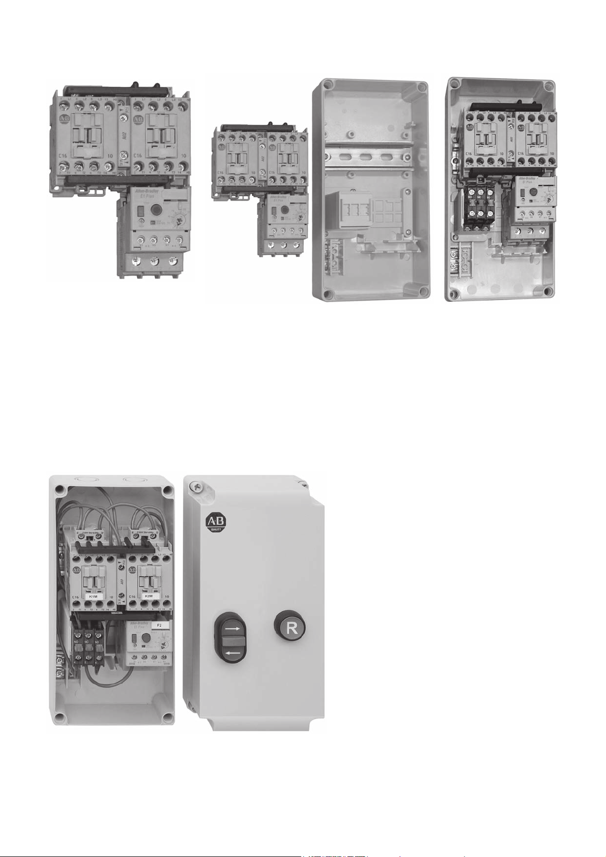
Assembly of Reversing Starters
21
Assemble the reversing starter:
• Place the mechanical interlock
between contactors
• Insert the dovetail connector
from rear side
• Attach the parallel connection
on line side
• Attach the reversing connection
and the overload relay on load side
3
Snap the starter combination onto the metal hat rail in the enclosure base.
Snap the 800F contact blocks onto the device support:
• Pos. 1 (left): N.O. contact
• Pos. 2 (center): N.C. contact
• Pos. 3 (left): N.O. contact
Do the control wiring according the wiring diagram / wiring table.
Mount the 800F push button operators into the cover.
(2)
Page 3

Component Selection for Reversing Starters
Contactors 100-C and Overload Relays 193-ED / 193-EE
Current
Range
Min
[A] [A]
0.10 0.50 0.06…0.09 0.06…0.12 0.06…0.12 0.06...0.18 23
0.20 2/1...4/13/1…4/155.0…52.073.0…81.052.0…81.021.00.1 46
1.0 5.0 0.18…1.1 0.37…1.5 0.55…2.2 0.75…3 1/4…3/4 1/4…1 1/2...2 3/4…3 16 20
3.2 11.3 1.5…3 2.2…4 3.0…4 4 1…2 1 1/2...2 3…5 5...7 1/2 20 20
3.2 15.0 4 5.5 5.5 5.5 3 3 7 1/2 10 25 20
3.2 16.0 7.5 7.5 7.5 337 1/2 10 32 30
5.7 5101555.50.02 35 40
5.7 26.5 7.5 10…11 10…13 10 5 7 1/2 15 15 40 40
To complete the cat. no., please replace with a coil voltage code.
The electronic overload relay 193-EE* can be taken as well.
230V
50Hz
Max DIN Fuses
[kW] [kW] [kW] [kW] [HP] [HP] [HP] [HP]
400V
50Hz
500V
50Hz
690V
50Hz
200V
60Hz
230V
60Hz
460V
60Hz
575V
60Hz
100kA,
690V
Type gL/gG
100kA,
600V
Max. Fuse
Class CC, J
Components
Contactor
100-C09 10
100-C09 10
100-C09 10
100-C09 10
100-C12 10
100-C16 10
100-C16 10
100-C23 10
Additional components
Mechanical / Electrical Interlock 1 100-MCA02
Power Wiring Kit for Reversing Starters 1
Neutral Terminal
¥
Control Components required for Impulse Control
Multi-Function Push Button Operator, 3 Functions, without Markings ठ1
Base Mounted Contact Block 1 N.C. 1
Base Mounted Contact Block 1 N.O. 2
Reset Push Button Operator, Marking "R" 1
Control Components required for Maintained Control
Selector Switch Operator, non-illuminated, 3-position § 1
Base Mounted Contact Block 1 N.O. 2
Reset Push Button Operator, Marking "R" 1
‡ For button caps with text or symbols, order the operator without cap (cat. no. 800FP-U3X ). Caps are to be ordered separately.
§
For legend plates and frames, please see catalog A116.
¥ For UL applications.
ytitnauQ deriuqeRnoitpircseD Cat. No.
1 198E-PNT
800FP-U3F3F34
800FP-F611
800FP-SM32
800FP-F611
Overload
Relay
193-ED1AB
193-ED1BB
193-ED1CB
193-ED1DB
193-ED1DB
193-ED1DB
193-ED1EB
193-ED1EB
105-PW23
800F-BX01
800F-BX10
800F-BX10
Schematic Diagram for Reversing Starters
2 2
1
1
Impulse Control, Multi Function Push Button
Add wires for common control. Remove if separate control is required.
1
5
6
V
K1M
L1
3-phase
N
1
3
5
2
K2M
64
F2
1
2
U
3
42
46
WARNING:
AVERTISSEMENT:
conduits métalliques.
Bonding between metallic conduits must be provided.
SUPPLY CONDUCTOR
SIZE (AWG)
GROUNDING ADAPTER KIT, CAT. NO. 198-GR1
SEE APPLICABLE CODES AND LAW
FOR GROUNDING REQUIREMENTS
Maintained Control, Selector Switch < O >
L1 Control voltage supplied from external source.
2
Une liaison électrique doit être assurée entre les
BONDING CONDUCTOR
QTY. SIZE
14
12
10
FOR USE WITH ALLEN-BRADLEY
1
1
2
14
12
12
M
1~
SINGLE-PHASE
(3)
Page 4

Schematic Diagram for Direct On-line Starters
3-phase 2-phase
WARNING:
AVERTISSEMENT:
conduits métalliques.
Bonding between metallic conduits must be provided.
SUPPLY CONDUCTOR
SIZE (AWG)
GROUNDING ADAPTER KIT, CAT. NO. 198-GR1
Dimensions
Single-phase
Une liaison électrique doit être assurée entre les
BONDING CONDUCTOR
14
12
10
FOR USE WITH ALLEN-BRADLEY
SEE APPLICABLE CODES AND LAW
FOR GROUNDING REQUIREMENTS
QTY. SIZE
1
1
2
125 [4.93]
14
12
12
12
2
1
Impulse Control
Multi Function Push Button
Add wires for common control. Remove if separate control is required.
1
L1 Control voltage supplied from external source.
2
125 [4.93]
Maintained Control
O - I Selector Switch
L1
1
2 2
1 When E-ST OP is used
969597
L1
2 WIRE
CONTROL
2
1
3
I
1- HAND
2- OFF
3- AUTO
98
Illuminated HOA Selector Switch
I
A1
A2
13 [0.51]
250 [9.85]
100 [3.94]
3.5 [0.14]
30 [1.18]
88.6 [3.49]
125 [4.93]
50 [1.97]
Ø23
[Ø0.91]
111.5 [4.39]
24 [0.95]
50 [1.97]
50 [1.97]
Pozidriv No. 2
Pozidriv No. 2
(1.2 x 6.5)
(1.2 x 6.5)
2.0 Nm
2.0 Nm
18 lb-in
18 lb-in
16
[0.63]
Rotary operator alternatively
(for maintained control)
28.1 [1.11]
2 x 1...6 mm²
2 x 1...6 mm²
2 x No. 14...10 AWG
2 x No. 14...10 AWG
235 [9.26]
110 [4.33]
10
10
Pozidriv No. 2
Pozidriv No. 2
2.3 Nm
2.3 Nm
20 lb-in
20 lb-in
DIR 10000400788 (Version 02)
Printed in Estonia
 Loading...