

Page 1

™
PICO
Programming
Take a closer look
11 Easy Steps
Small.
Simple.
Flexible.
Page 2
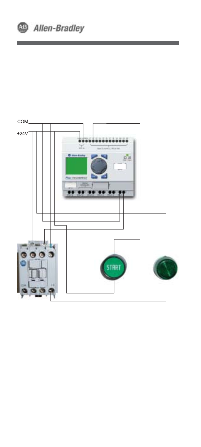
Schematic Diagram (for Demo Unit)
Page 3

PICO™ Programming
Program PICO yourself in
11 Easy Steps.
After the completion of the following
exercise, you will have programmed the
Allen-Bradley PICO Controller. The
program simulates starting a motor for
10 seconds and then turns the motor off.
Your program will look like the following:
I
2 - - - - - - - - SQ6
Q6 - - - - - - - - TT1
T1 - - - - - - - - RQ6
I
2
Physical input #2 to which the START button
is wired to.
This sets, or latches output #6 to which the
SQ6
coil of the contactor is wired to.
Q6
Output #6 (contactor coil) contact
TT1
On delay Timer #1 (10 seconds)
T1
Timer#1 contact
RQ6
This resets, or unlatches output #6.
Page 4

PICO Touch Pad
Delete buttonDelete button
(Del)
P1 P3
P2
Alternate
button
(Alt)
Escape button
(Esc)
The following instructions make use of of the 8 buttons
displayed above
The “P” buttons
The “P” buttons move the cursor, right and left (P1,P3)
or up and down (P2,P4)
P4
OK button
Smarter Than Your Average Relay
Easier to use than
a PLC
- No software required
- Easy to program
Page 5
PROGRAM. . .
STOP
PARAMETER
SET CLOCK. . .
PICO™ Programming
Deleting the existing
program
Press the OK button until you
see the menu to the left. If
the second menu item down
is STOP, press P4 and press
OK. If not, highlight
PROGRAM and press the OK
button. To select DELETE
PROG Press P4 and press the
OK button twice.
PROGRAM
DELETE PROG
Entering Program mode
Highlight PROGRAM and
press the OK button.
Page 6

PICO Touch Pad
Delete buttonDelete button
(Del)
P1 P3
P2
Alternate
button
(Alt)
Escape button
(Esc)
The following instructions make use of of the 8 buttons
displayed above
The “P” buttons
The “P” buttons move the cursor, right and left (P1,P3)
or up and down (P2,P4)
P4
OK button
Smarter Than Your Average Relay
Even better than a
single-board
controller
Standard, off-the-shelf
product that is already
developed
World-wide support
and programming
knowledge.
Page 7

PICO™ Programming
Adding an input
instruction
I
2
Press the OK button to inset
the first instruction. You’ll
notice the “
Your screen should look like
this at the end of Step 3.
I
” flashing.
Changing the input
contact number
I
2
Press P3 to highlight the “1”.
Press P2 and change the the
input to
button followed by the Alt
button. Your display should
look similar to the one to the
left.
I
2. Press the OK
Page 8

PICO Touch Pad
Delete buttonDelete button
(Del)
P1 P3
P2
Alternate
button
(Alt)
Escape button
(Esc)
The following instructions make use of of the 8 buttons
displayed above
P4
OK button
The “P” buttons
The “P” buttons move the cursor, right and left (P1,P3)
or up and down (P2,P4)
Smarter Than Your Average Relay
Intelligent relay
replacement
Changing system
functions is a simple
matter of
reprogramming PICO.
No rewiring necessary!
Cost effectively
replaces 3-4 control
relays and/or 1 timing
relay.
Page 9

I
2 - - - - - - - - SQ6
Your screen should look like
this at the end of Step 5.
PICO™ Programming
Adding a latched output
instruction
Press P3 three times. Next
press the OK button. You
should see a flashing “Q”.
Press P1 once. The cursor
should move to the flashing
bracket. Press P2 twice to
change the bracket to “S”
(set). Press P3 twice to move
the cursor to the flashing
“1”, followed by pressing P2
to change the 1 to a 6. Press
the OK button.
I
2 - - - - - - - - SQ6
Q6 - - - - - - - -
Your screen should look like
this at the end of Step 6.
Using an output contact
to start a timer
Press the OK button to inset
the I1 input. While on the
flashing “
I
” press P2 until I
changes to “Q”. Press P3.
Change the flashing “1” to
“6” by pressing the P2
button. Press the OK button.
Press the Alt button to insert
the rung lines and the P3
button three times.
Page 10

PICO Touch Pad
Delete buttonDelete button
(Del)
P1 P3
P2
Alternate
button
(Alt)
Escape button
(Esc)
The following instructions make use of of the 8 buttons
displayed above
The “P” buttons
The “P” buttons move the cursor, right and left (P1,P3)
or up and down (P2,P4)
P4
OK button
Smarter Than Your Average Relay
Permanent program
retention
Programs are stored in
non-volatile EEPROM
memory, and will not
be lost in the event of
a power failure.
Page 11
I
2 - - - - - - - - SQ6
Q6 - - - - - - - - TT1
PICO™ Programming
Adding a timer-timing
contact
Press the OK button to insert
an output. Press P2 three
times to display the TT1
timing contact.
Your screen should look like
this at the end of Step 7.
Inserting a timer
Press the OK button three
X
00
S
TRG
C
RES
T1
+
times. Press P2 until the
flashing “
“T”. Press the OK button
twice and you will jump to
the screen shown in step 9.
I
” changes to a
Page 12

PICO Touch Pad
Delete buttonDelete button
(Del)
P1 P3
P2
Alternate
button
(Alt)
Escape button
(Esc)
The following instructions make use of of the 8 buttons
displayed above
The “P” buttons
The “P” buttons move the cursor, right and left (P1,P3)
or up and down (P2,P4)
P4
OK button
Smarter Than Your Average Relay
Commissioning
status display
View the real-time
analysis of the logic
circuit.
Page 13

PICO™ Programming
Configuring the 10 second
timer
Now you will enter a preset
X
10.00
S
TRG
C
RES
T1
+
timer value for Timer #1.
Press P1 and then the P3
button twice. You should be
on the “0”. Press P2 to
change the “0” to a “1”.
Your display should now look
like the screen to the left.
Press the OK button twice.
I
2 - - - - - - - - SQ
Q6 - - - - - - - - TT1
T1 - - - - - - - - RQ6
Your screen should look like
this at the end of Step 10.
Unlatch the output contact
Press the Alt button followed
by the the P3 button three
times. Press Okay Button.
Press P1 to move the cursor
to the flashing bracket. Press
P2 once to change the bracket
to “R” (reset). Press P3 twice
to move the cursor the
flashing “1”. Press P2 to
change the display to the
number “6”. Press the OK
button.
Page 14

PICO Touch Pad
Delete buttonDelete button
(Del)
P1 P3
P2
Alternate
button
(Alt)
Escape button
(Esc)
The following instructions make use of of the 8 buttons
displayed above
The “P” buttons
The “P” buttons move the cursor, right and left (P1,P3)
or up and down (P2,P4)
P4
OK button
Smarter Than Your Average Relay
Password security
Control access to the
program and
parameters.
Page 15

PICO™ Programming
Saving & Running your
program
Press the ESC button to save
PROGRAM. . .
STOP
PARAMETER
SET CLOCK. . .
In Run Mode
Press the Start button. This will SET Output #6 which picks
up the coil in the contactor and turns on the green pilot
light. At the same time, it also starts a 10 second timer.
Once that timer has completed, it will RESET Output #6
and drops the coil in the contactor, which turns off the
pilot light.
Congratulations, you have successfully
programmed the PICO Controller!
the program to memory.
Press the Esc button again to
take you to the Main menu.
Press P4 to go to “RUN”
mode. Press Okay.
(see screen to left)
Press the Esc button to take
you to the front display.
OPTIONAL Steps
While on the front display press the OK button twice.
You will be able to see the program while in Run mode.
You can notice what rungs are active by noticing the
highlighted rungs.
Press Esc, press P2 twice to highlight the Parameter
button. Press OK. You will now be monitoring the T1 timer.
Press the Start button to see the timer count up to 10.
In this mode you can also change the Preset value
of the timer.
Page 16

www.rockwellautomation.com
Corporate Headquarters
Rockwell Automation, 777 East Wisconsin Avenue, Suite 1400, Milwaukee,
WI, 53202-5302 USA, Tel: (1) 414.212.5200, Fax: (1) 414.212.5201
Headquarters for Allen-Bradley Products, Rockwell Software Products
and Global Manufacturing Solutions
Americas: Rockwell Automation, 1201 South Second Street, Milwaukee,
WI 53204-2496 USA, Tel: (1) 414.382.2000, Fax: (1) 414.382.4444
Europe/Middle East/Africa: Rockwell Automation SA/NV, Vorstlaan/Boulevard
du Souverain 36, 1170 Brussels, Belgium,
Tel: (32) 2 663 0600, Fax: (32) 2 663 0640
Asia Pacific: Rockwell Automation, 27/F Citicorp Centre, 18 Whitfield Road,
Causeway Bay, Hong Kong, Tel: (852) 2887 4788, Fax: (852) 2508 1846
Headquarters for Dodge and Reliance Electric Products
Americas: Rockwell Automation, 6040 Ponders Court, Greenville,
SC 29615-4617 USA, Tel: (1) 864.297.4800, Fax: (1) 864.281.2433
Europe/Middle East/Africa: Rockwell Automation, Brühlstraße 22,
D-74834 Elztal-Dallau, Germany, Tel: (49) 6261 9410, Fax: (49) 6261 17741
Asia Pacific: Rockwell Automation, 55 Newton Road, #11-01/02
Revenue House, Singapore 307987, Tel: (65) 6356-9077, Fax: (65) 6356-9011
Publication 1760-QS001A-EN-P – April 2003
Copyright © 2002 Rockwell Automation, Inc.. All rights reser ved. Printed in Canada.
 Loading...