

Page 1

DataSite Accelerator Toolkit
Quick Start
Hardware Selection
System Layout and Wiring
DataSite and Logix Integration
DataSite Workbench and Screen Builder Integration
FactoryTalk View Integration
System Validation
Page 2
Important User Information
Solid state equipment has operational characteristics differing from those of electromechanical equipment. Safety
Guidelines for the Application, Installation and Maintenance of Solid State Controls (publication SGI-1.1
your local Rockwell Automation sales office or online at http://literature.rockwellautomation.com
portant differences between solid state equipment and hard-wired electromechanical devices. Because of this difference, and also because of the wide variety of uses for solid state equipment, all persons responsible for applying this
equipment must satisfy themselves that each intended application of this equipment is acceptable.
In no event will Rockwell Automation, Inc. be responsible or liable for indirect or consequential damages resulting
from the use or application of this equipment.
The examples and diagrams in this manual are included solely for illustrative purposes. Because of the many variables
and requirements associated with any particular installation, Rockwell Automation, Inc. cannot assume responsibility
or liability for actual use based on the examples and diagrams.
No patent liability is assumed by Rockwell Automation, Inc. with respect to use of information, circuits, equipment,
or software described in this manual.
Reproduction of the contents of this manual, in whole or in part, without written permission of Rockwell Automation,
Inc., is prohibited.
Throughout this manual, when necessary, we use notes to make you aware of safety considerations.
available from
) describes some im-
WARNING
Identifies information about practices or circumstances that can cause an explosion in a
hazardous environment, which may lead to personal injury or death, property damage, or
economic loss.
IMPORTANT
ATTENTION
Identifies information that is critical for successful application and understanding of the product.
Identifies information about practices or circumstances that can lead to personal injury or death,
property damage, or economic loss. Attentions help you identify a hazard, avoid a hazard, and
recognize the consequence
SHOCK HAZARD
Labels may be on or inside the equipment, for example, a drive or motor, to alert people that
dangerous voltage may be present.
BURN HAZARD
Labels may be on or inside the equipment, for example, a drive or motor, to alert people that
surfaces may reach dangerous temperatures.
Allen-Bradley, ControlLogix, DataSite, FactoryTalk, FactoryTalk View ME, FactoryTalk View SE, PanelView, PanelView Plus, RSLogix 5000, RSLinx, Rockwell Automation, and TechConnect are
trademarks of Rockwell Automation, Inc.
Trademarks not belonging to Rockwell Automation are property of their respective companies.
Page 3
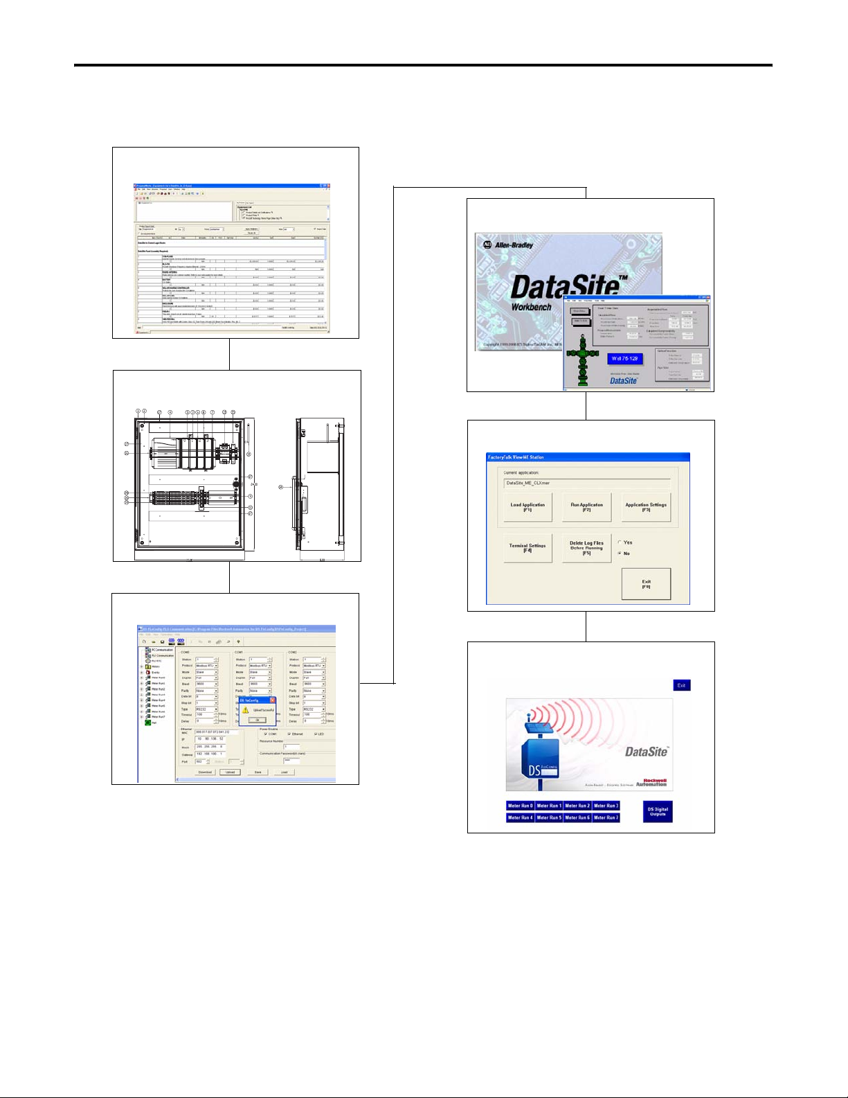
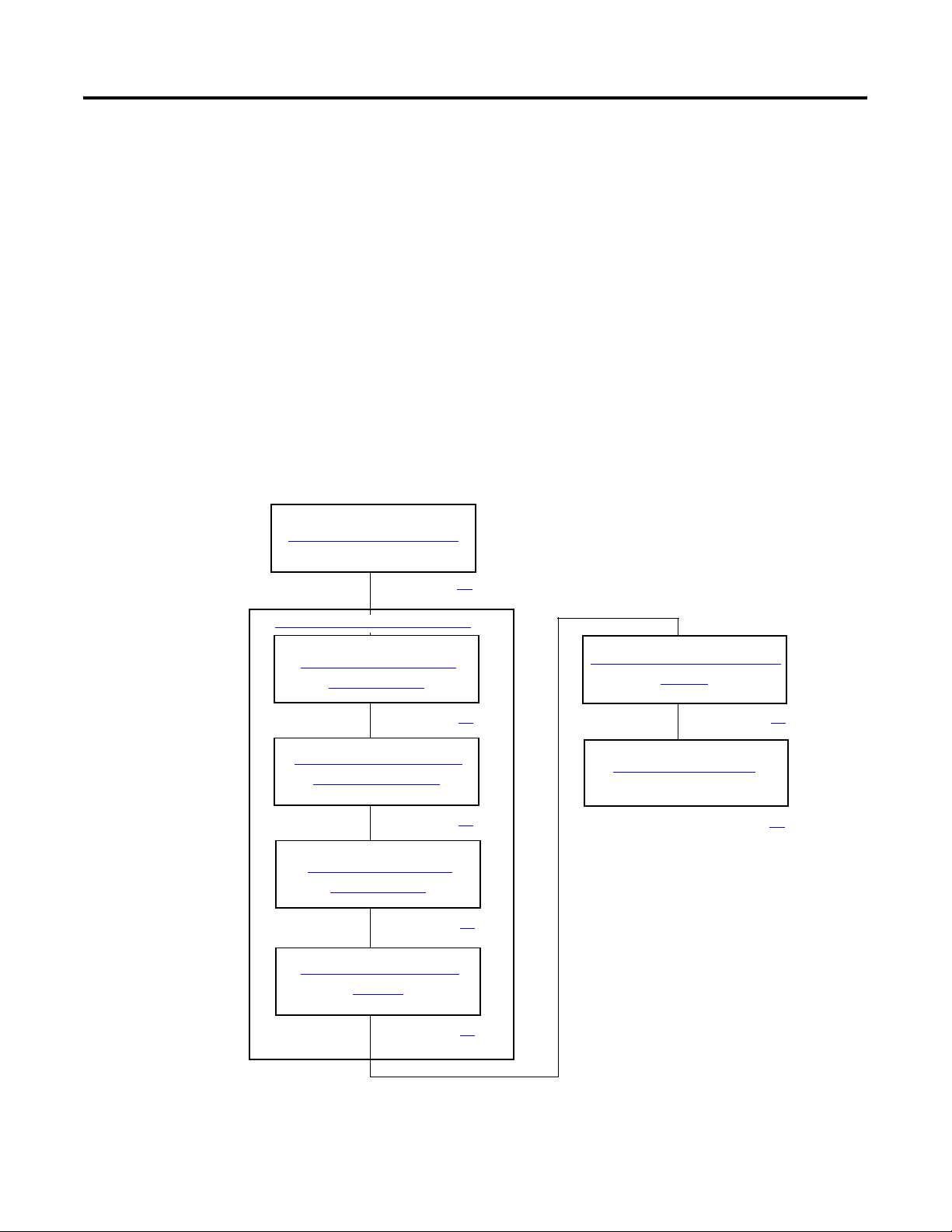
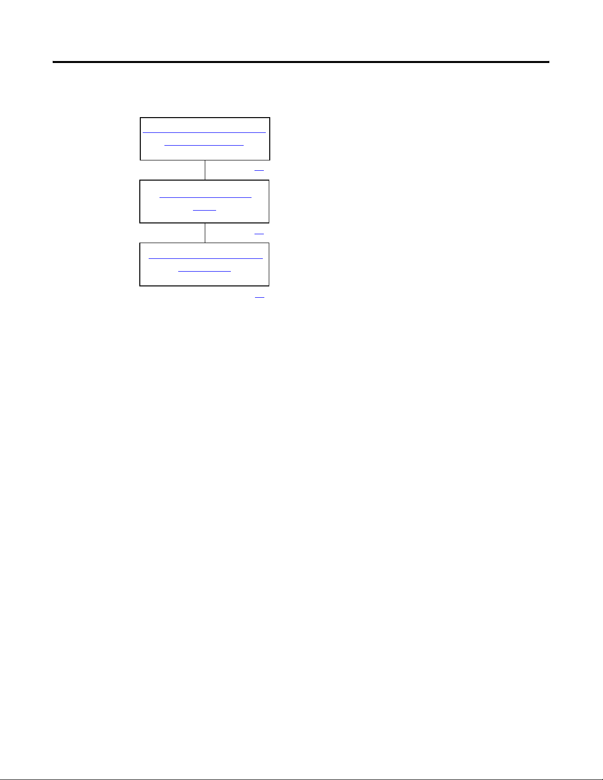
Follow this path to complete your DataSite application.
Chapter 1
Hardware Selection
Chapter 2
System Layout and Wiring
Where to Start
Chapter 4
DataSite Workbench and Screen Builder Integration
Chapter 5
FactoryTalk View Integration
Chapter 3
DataSite and Logix Integration
Chapter 6
System Validation
3Publication IASIMP-QS008A-EN-P - March 2009 3
Page 4
Where to Start
DataSite Configurations
This quick start shows how to set up and configure three functional DataSite configurations.
• DataSite to ControlLogix master (
• DataSite to FactoryTalk View ME master (
• DataSite to FactoryTalk View SE master with data logging capabilities (
Chapter 1 through 6)
Appendix A)
Appendix B)
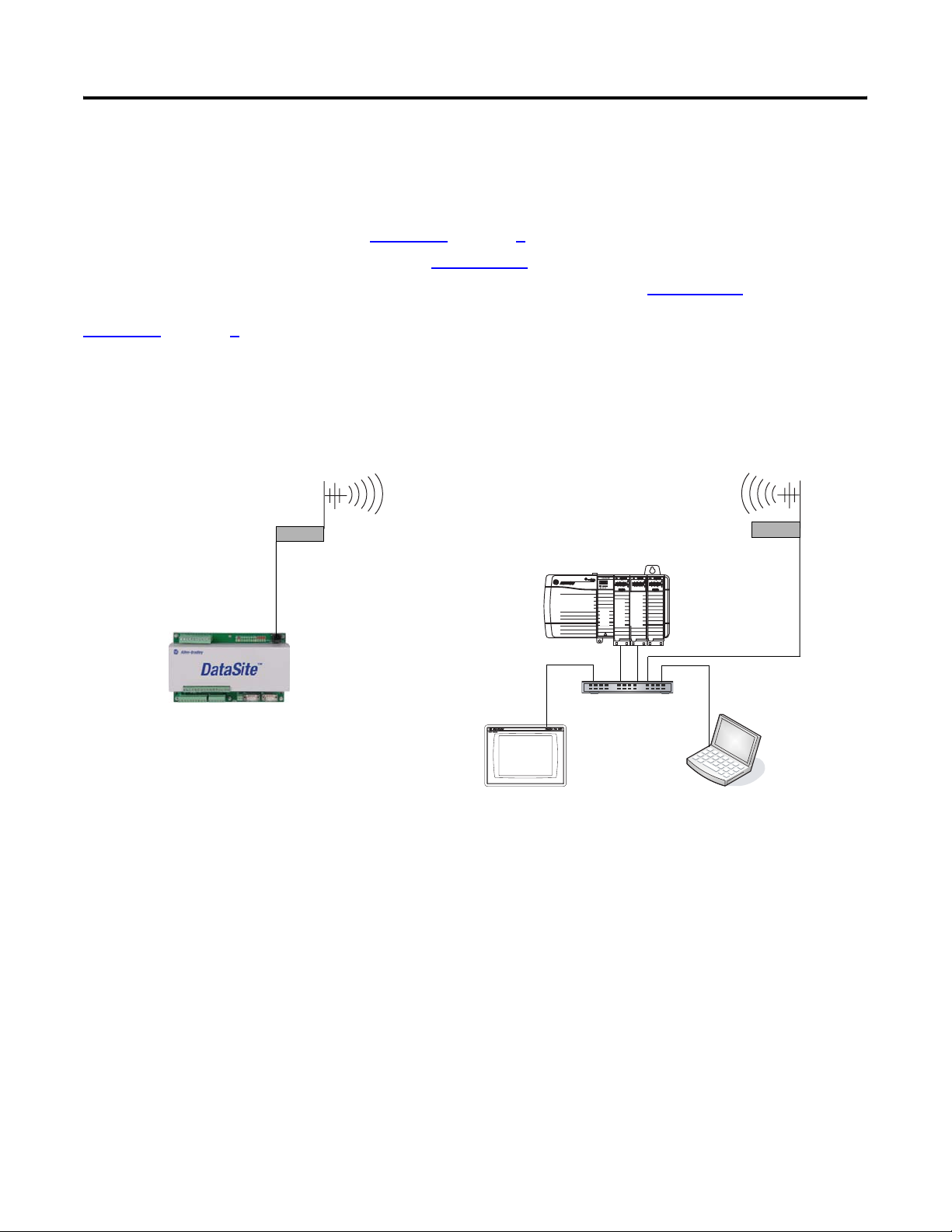
Chapter 1 through 6 cover the DataSite to ControlLogix Master configuration. In this configuration, a
DataSite unit communicates via RF radio modems to a ControlLogix L63 controller and displays the natural
gas flow data on a PanelView Plus 1000 terminal.
DataSite to ControlLogix Master
Remote Location
Radio
Ethernet
Crossover Cable
2711P-CBL-EX04
with 1756-ENBT Ethernet/IP and ProSoft Module
Host Location
1756-L63 ControlLogix Controller
Chassis
ProSoft
ENBT
L63
Radio
1758-FLO302 Datasite
Ethernet Switch
2711P PanelView Plus 1000 Terminal
with Built-in Ethernet Port
All devices connect to Ethernet switch using Ethernet straight-through cables.
Computer
4 Publication IASIMP-QS008A-EN-P - March 2009
Page 5
Where to Start
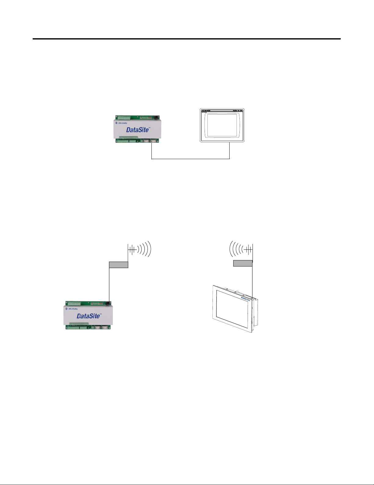
The DataSite to FactoryTalk View ME Master configuration is good for small applications that don’t require
a ControlLogix controller to poll multiple DataSite units. The PanelView Plus 600 terminal communicates
with the DataSite unit using Modbus serial communication.
DataSite to FactoryTalk View ME Master
2711P PanelView Plus 600 Terminal
1758-FLO302 Datasite
2711-NC13 Serial Cable
The Factory Talk View SE Master configuration is good for small applications that don’t require a
ControlLogix controller but do require data logging capabilities. The industrial computer running
FactoryTalk View SE communicates with the DataSite using Modbus TCP/IP Ethernet communication.
DataSite to FactoryTalk View SE Master
Remote Location
Radio
Ethernet
Crossover Cable
2711P-CBL-EX04
1758-FLO302 Datasite
Host Location
Radio
Ethernet
Crossover Cable
2711P-CBL-EX04
6181P Industrial Computer Running
FactoryTalk View SE
Publication IASIMP-QS008A-EN-P - March 2009 5
Page 6

Where to Start
6 Publication IASIMP-QS008A-EN-P - March 2009
Page 7

Hardware Selection
System Layout and Wiring
Table of Contents
Preface
About This Publication . . . . . . . . . . . . . . . . . . . . . . . . . . . . . 9
Software Requirements . . . . . . . . . . . . . . . . . . . . . . . . . . . . 10
Conventions . . . . . . . . . . . . . . . . . . . . . . . . . . . . . . . . . . . . 10
Additional Resources. . . . . . . . . . . . . . . . . . . . . . . . . . . . . . 11
Chapter 1
Introduction . . . . . . . . . . . . . . . . . . . . . . . . . . . . . . . . . . . . 13
Before You Begin . . . . . . . . . . . . . . . . . . . . . . . . . . . . . . . . 13
What You Need . . . . . . . . . . . . . . . . . . . . . . . . . . . . . . . . . 13
Review Basic Panel Component Listings. . . . . . . . . . . . . . . . 14
Chapter 2
Introduction . . . . . . . . . . . . . . . . . . . . . . . . . . . . . . . . . . . . 17
Before You Begin . . . . . . . . . . . . . . . . . . . . . . . . . . . . . . . . 17
What You Need . . . . . . . . . . . . . . . . . . . . . . . . . . . . . . . . . 17
Follow These Steps . . . . . . . . . . . . . . . . . . . . . . . . . . . . . . . 18
Review DataSite Connections. . . . . . . . . . . . . . . . . . . . . . . . 18
Plan Your DataSite Panel Layout and Wiring . . . . . . . . . . . . 19
Verifying Your Basic Panel Layout . . . . . . . . . . . . . . . . . . . . 20
Download Other Allen-Bradley CAD Drawings. . . . . . . . . . . 24
DataSite and Logix Integration
DataSite Workbench and Screen
Builder Integration
Chapter 3
Introduction . . . . . . . . . . . . . . . . . . . . . . . . . . . . . . . . . . . . 25
Before You Begin . . . . . . . . . . . . . . . . . . . . . . . . . . . . . . . . 25
What You Need . . . . . . . . . . . . . . . . . . . . . . . . . . . . . . . . . 25
Follow These Steps . . . . . . . . . . . . . . . . . . . . . . . . . . . . . . . 26
Configure the DataSite Unit . . . . . . . . . . . . . . . . . . . . . . . . . 27
Configuring the Logix Controller . . . . . . . . . . . . . . . . . . . . . 31
Configure the ProSoft Modbus Module. . . . . . . . . . . . . . . . . 36
Connecting All Devices . . . . . . . . . . . . . . . . . . . . . . . . . . . . 42
Chapter 4
Introduction . . . . . . . . . . . . . . . . . . . . . . . . . . . . . . . . . . . . 43
Before You Begin . . . . . . . . . . . . . . . . . . . . . . . . . . . . . . . . 43
What You Need . . . . . . . . . . . . . . . . . . . . . . . . . . . . . . . . . 43
Follow These Steps . . . . . . . . . . . . . . . . . . . . . . . . . . . . . . . 44
Download the DataSite User Program . . . . . . . . . . . . . . . . . 45
Download the DataSite Web Pages . . . . . . . . . . . . . . . . . . . 49
7Publication IASIMP-QS008A-EN-P - March 2009 7
Page 8

Table of Contents
FactoryTalk View Integration
System Validation
Chapter 5
Introduction . . . . . . . . . . . . . . . . . . . . . . . . . . . . . . . . . . . . 53
Before You Begin . . . . . . . . . . . . . . . . . . . . . . . . . . . . . . . . 53
What You Need . . . . . . . . . . . . . . . . . . . . . . . . . . . . . . . . . 53
Follow These Steps . . . . . . . . . . . . . . . . . . . . . . . . . . . . . . . 54
Load and Restore FactoryTalk View ME Application . . . . . . . 54
Configure Local Communication . . . . . . . . . . . . . . . . . . . . . 56
Configure Target Communication . . . . . . . . . . . . . . . . . . . . 59
Download Project to PanelView Plus Terminal . . . . . . . . . . . 61
Run the Project on PanelView Plus Terminal . . . . . . . . . . . . 64
Chapter 6
Introduction . . . . . . . . . . . . . . . . . . . . . . . . . . . . . . . . . . . . 67
Before You Begin . . . . . . . . . . . . . . . . . . . . . . . . . . . . . . . . 67
What You Need . . . . . . . . . . . . . . . . . . . . . . . . . . . . . . . . . 67
Follow These Steps . . . . . . . . . . . . . . . . . . . . . . . . . . . . . . . 68
Validate DataSite to PanelView Plus Communication . . . . . . 69
Validate DataSite Web Pages . . . . . . . . . . . . . . . . . . . . . . . . 75
Review DataSite Workbench User Program . . . . . . . . . . . . . 80
DataSite to FactoryTalk View ME
Master
DataSite to FactoryTalk View SE
Master
Appendix A
Before You Begin . . . . . . . . . . . . . . . . . . . . . . . . . . . . . . . . 81
What You Need . . . . . . . . . . . . . . . . . . . . . . . . . . . . . . . . . 81
Follow These Steps . . . . . . . . . . . . . . . . . . . . . . . . . . . . . . . 82
Load KEPServerEnterprise File . . . . . . . . . . . . . . . . . . . . . . . 83
Load FactoryTalk View ME Application . . . . . . . . . . . . . . . . 85
Validate Communication Between DataSite and Terminal . . . 88
Select a Different COM Port for the Serial DF1 Driver . . . . . . 91
Appendix B
Before You Begin . . . . . . . . . . . . . . . . . . . . . . . . . . . . . . . . 95
What You Need . . . . . . . . . . . . . . . . . . . . . . . . . . . . . . . . . 96
Follow These Steps . . . . . . . . . . . . . . . . . . . . . . . . . . . . . . . 96
Load KEPServerEnterprise File . . . . . . . . . . . . . . . . . . . . . . . 97
Load FactoryTalk View SE Application . . . . . . . . . . . . . . . . . 99
Validate Communication Between DataSite and Computer . 106
Rockwell Automation Support . . . . . . . . . . . . . . . . . . . . . . 112
8 Publication IASIMP-QS008A-EN-P - March 2009
Page 9

Preface
About This Publication
This quick start provides step-by-step instructions on how to set up
and configure three functional DataSite configurations.
• DataSite to a ControlLogix master (Chapter 1
• DataSite to a FactoryTalk View Machine Edition (ME) master
(Appendix
• DataSite to a FactoryTalk View Site Edition (SE) master with data
logging capabilities (Appendix
The examples are designed to get devices installed and
communicating with each other in the simplest way possible. The
programming is not complex and offers easy solutions to verify that
devices are communicating properly
To assist in the design and installation of your DataSite configuration,
application files and other information is provided on the DataSite
Accelerator Toolkit CD, publication IASIMP-SP011. This CD provides
CAD drawings for panel layout and wiring, base Logix control
programs, FactoryTalk View HMI application files, and more. For a
copy of the CD, contact your local Rockwell Automation distributor or
sales representative. With these tools and the built-in best-practices
design, you can focus on the design of your system and not on design
overhead tasks.
A)
B)
through 6)
IMPORTANT
The beginning of each chapter contains the following information.
Read these sections carefully before beginning work in each chapter.
• Before You Begin - This section lists the steps that must be
completed and decisions that must be made before starting that
chapter. The chapters in this quick start do not have to be
completed in the order in which they appear, but this section
defines the minimum amount of preparation required before
completing the current chapter.
• What You Need - This section lists the tools that are required to
complete the steps in the current chapter. This includes, but is
not limited to, hardware and software.
• Follow These Steps - This illustrates the steps in the current
chapter and identifies which steps are required to complete the
examples using specific networks.
Before using this quick start and the contents of the DataSite
Accelerator CD, read the Terms and Conditions on the CD.
9Publication IASIMP-QS008A-EN-P - March 2009 9
Page 10
Preface
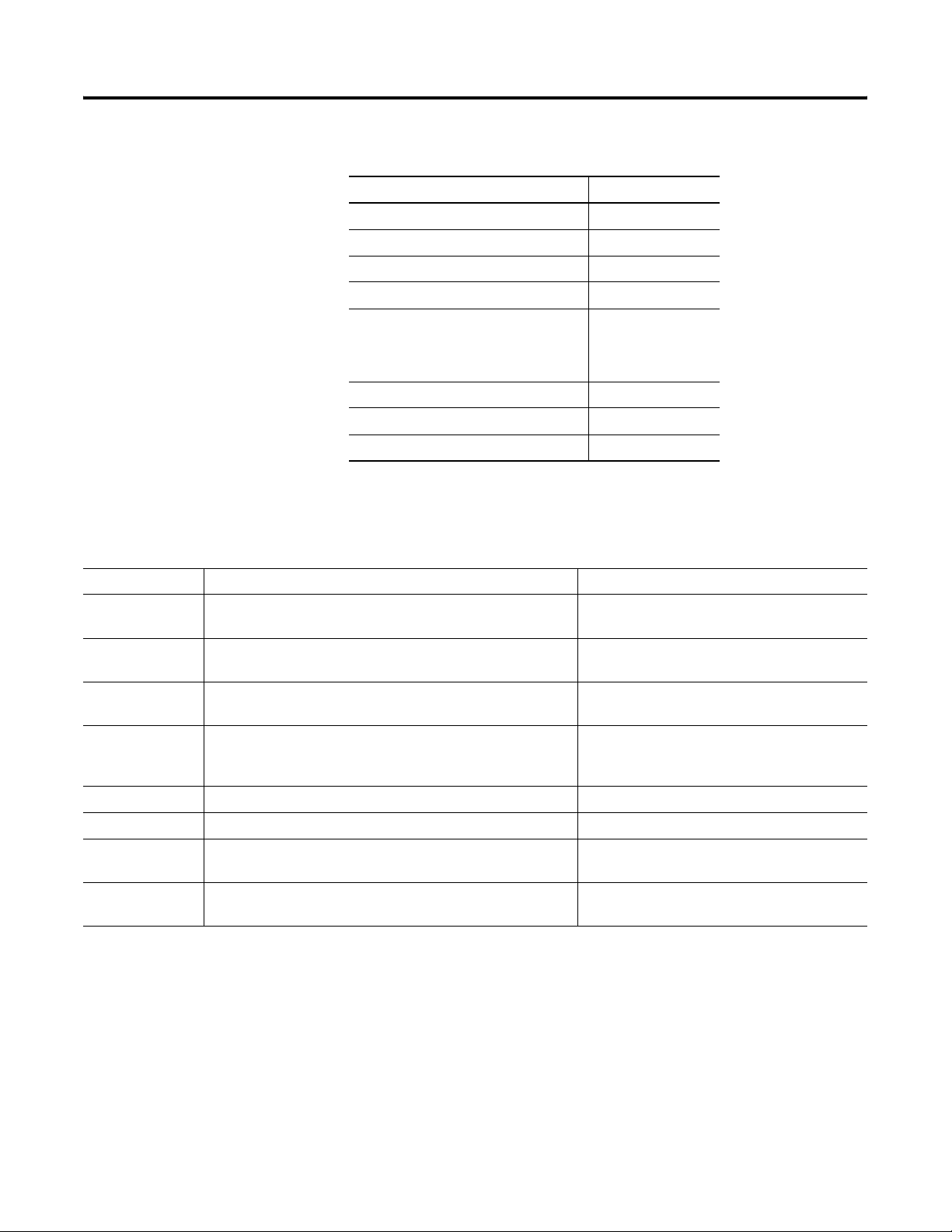
Software Requirements
Conventions
Convention Meaning Example
Click
Click the left mouse button once. (Assumes cursor is positioned
on object or selection.)
You need the following software to use this toolkit.
Rockwell Automation Software Version
DataSite Workbench 5.2
DataSite Screen Builder 1.3
DS FloConfig 1.0
RSLogix 5000 16
FactoryTalk View Studio, including:
• Machine Edition (ME)
• Site Edition (SE)
Proposal Works 6.1
Java Runtime Environment 6, Update 7
DataSite Accelerator Toolkit CD Not applicable
5.0
This quick start uses the following conventions.
Click Browse.
Double-click
Right-click
Drag and drop
Select Click to highlight a menu item or list choice. Select New Module from the pull-down list.
Check or uncheck Click to activate or deactivate a checkbox. Check the Disable Keying checkbox.
> Shows nested menu selections as menu name followed by menu
Expand
Click the left mouse button twice in quick succession while the
cursor is positioned on object or selection.
Click the right mouse button once while the cursor is positioned
on object or selection.
Click and hold the left mouse button on an object, move the
cursor to where you want to move the object, and release the
mouse button.
selection.
Click the + to the left of a given item /folder to show its
contents.
Double-click the application icon.
Right-click the Fieldbus Networks icon.
Drag and drop the desired block into the Strategy
window.
Select File>New.
Expand the Main Task.
10 Publication IASIMP-QS008A-EN-P - March 2009
Page 11

Additional Resources
Resource Description
Preface
DataSite Natural Gas Flow Meter and Remote Terminal
Unit Installation Instructions, publication 1758-IN001
DataSite Electronic Flow Meter and Remote Terminal
User Manual, publication 1758-UM001
Customized Function Blocks for DataSite Reference
Manual, publication 1758-RM001
DataSite Electronic Flow Meter and Remote Terminal,
Software User Manual, publication 1758-UM002
http://www.ab.com/programmablecontrol/plc/datasite
Rockwell Automation Configuration and Selection Tools,
available at
http://www.rockwellautomation.com/en/e-tools/
http://www.rockwellautomation.com/solutions/integrat
edarchitecture/
http://www.prosoft-technology.com/
Describes how to install and wire the Datasite unit.
Describes how to design, install, program, or troubleshoot control systems that
use DataSite controllers.
Describes the customized function blocks that are used to program DataSite
units using DataSite Workbench software.
Describes the software tools that are used to configure and monitor the
DataSite controller, such as DS settings, DS FloConfig, and DS NP3.
Provides information related to the DataSite unit.
These online tools install on your personal computer so that you can quickly
access information on our products.
• Proposal Works
• Industrial Computer Selector
• Operator Interface Selection Tool
• Programmable Controller Family Selector
Provides information on integrated architecture tools and resources including
accelerator toolkits.
Provides information regarding ProSoft Technology products and technical
support. The Modbus TCP/IP Communication Module (MVI56-MNET) used in
this quick start is a product of ProSoft Technology.
Contact technical support by emailing support@prosoft-technology.com or
calling 1 + (661) 716-5100.
You can view or download publications at
http://literature.rockwellautomation.com
. To order paper copies of
technical documentation, contact your local Rockwell Automation
distributor or sales representative.
Publication IASIMP-QS008A-EN-P - March 2009 11
Page 12

Preface
12 Publication IASIMP-QS008A-EN-P - March 2009
Page 13

Chapter
1
Hardware Selection
Introduction
In this chapter, you select the hardware for your application. You can select any of the three
DataSite configurations covered in this quick start. Within each configuration, you have the
option to purchase a pre-assembled DataSite panel or one that requires assembly. This chapter
provides step-by-step instructions on how to use the Bill of Materials (BOM) provided with the
DataSite Accelerator Toolkit CD.
Before You Begin
Verify that your computer meets the software requirements of Proposal Works software.
What You Need
• DataSite Accelerator Toolkit CD, publication IASIMP-SP011
For a copy of the CD, contact your local Rockwell Automation distributor or sales
representative.
• Personal computer with Internet access for downloading software.
13Publication IASIMP-QS008A-EN-P - March 2009 13
Page 14
Chapter 1 Hardware Selection
Review Basic Panel Component Listings
The bill of materials (BOM) on the DataSite Accelerator Toolkit CD includes the necessary
components to duplicate the three DataSite configurations covered in this quick start. Review the
component listings and compare with your specific application needs.
Follow these steps to view the BOM on the DataSite Accelerator Toolkit CD for the DataSite to
ControlLogix Master configuration.
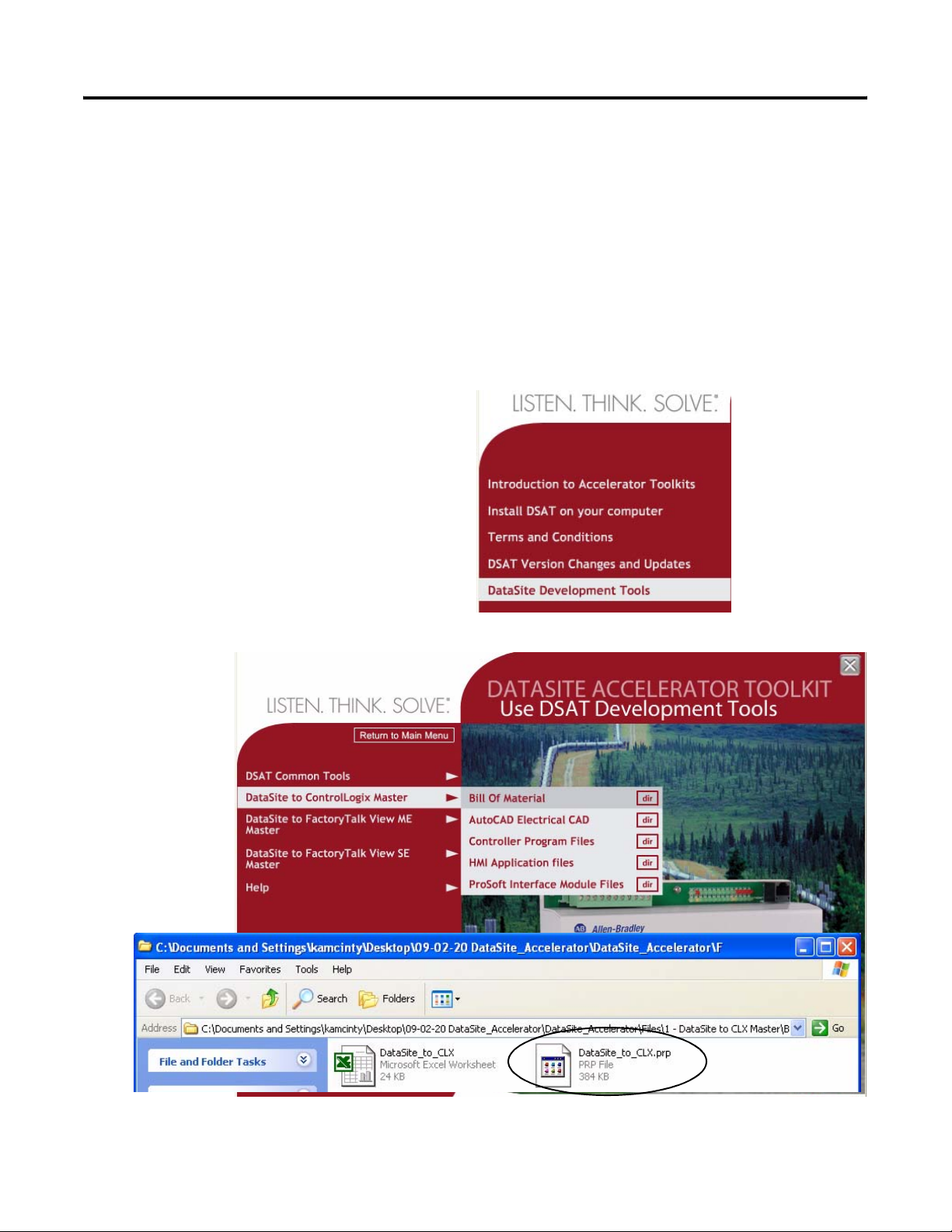
1. Launch the DataSite Accelerator Toolkit CD.
2. Select DataSite Development Tools.
3. Choose DataSite to ControlLogix
Master>Bill of Material, then double-click
DataSite_to_CLX.prp.
14 Publication IASIMP-QS008A-EN-P - March 2009
Page 15
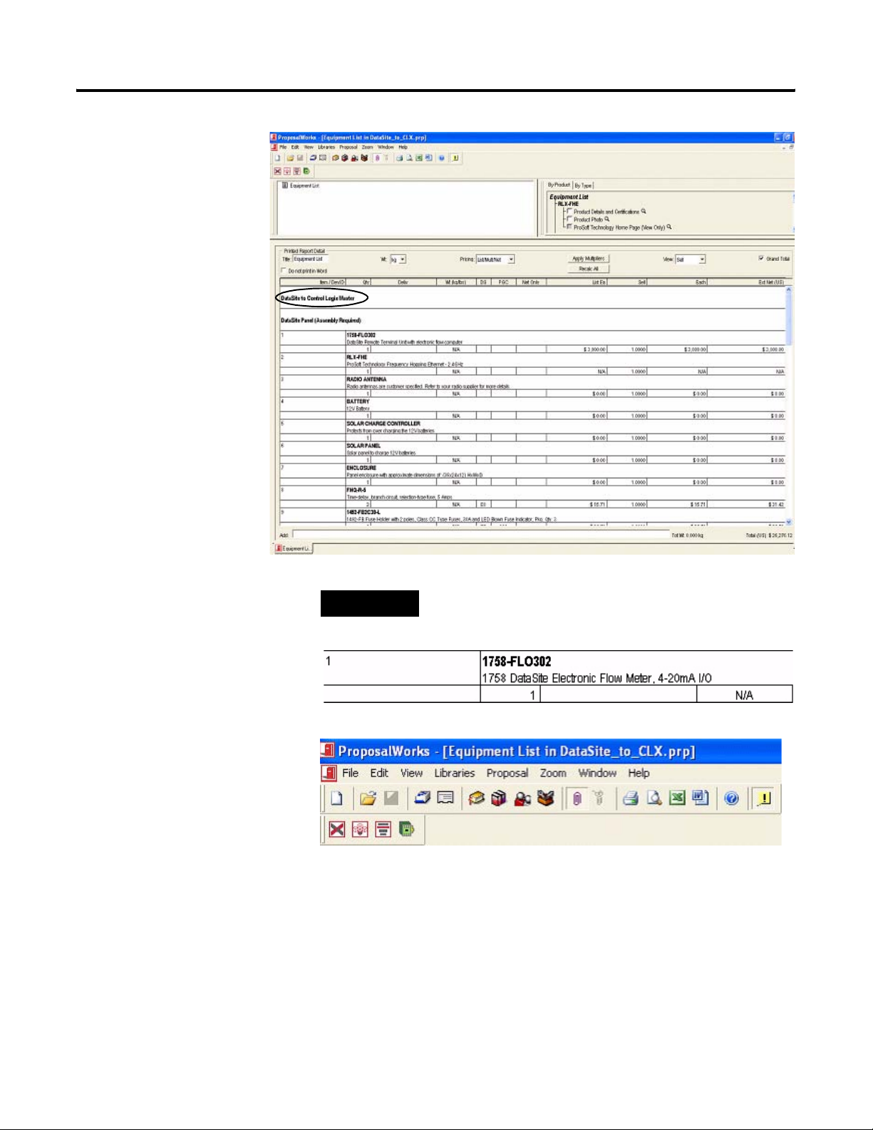
Proposal Works
launches and
displays the BOM
for the DataSite to
ControlLogix Master
configuration.
4. Review the BOM
and modify to fit
your application.
Hardware Selection Chapter 1
TIP
Double-click a bolded part number to launch the configurator
where you can modify components on the bill of material
5. After finalizing the BOM,
click the Word icon on
the toolbar to convert the
BOM to a Word
document.
Word launches and
displays the BOM.
6. Repeat steps 2 - 5 to view the BOMs for the other two DataSite configurations.
• DataSite Development Tools>DataSite to FactoryTalk View ME Master>Bill of
Material>DataSite_to ME_.prp.
• DataSite Development Tools>DataSite to FactoryTalk View SE Master>Bill of
Material>DataSite_to_SE.prp.
Publication IASIMP-QS008A-EN-P - March 2009 15
Page 16

Chapter 1 Hardware Selection
16 Publication IASIMP-QS008A-EN-P - March 2009
Page 17

Chapter
2
System Layout and Wiring
Introduction
In this chapter, you plan the panel layout and wiring for your DataSite system. You can use the
AutoCAD electrical drawings supplied on the DataSite Accelerator Toolkit CD to add or remove
components in your DataSite system.
Before You Begin
Complete your system hardware selection (Chapter 1).
What You Need
• DataSite Accelerator Toolkit CD, publication IASIMP-SP011
For a copy of the CD, contact your local Rockwell Automation distributor or sales
representative.
• AutoCAD electrical software to open DWG or DXF files.
TIP
• Adobe Acrobat Reader software to open PDF files.
• System Design for Control of Electrical Reference Manual, publication GMC-RM001.
• Documentation for your other Allen-Bradley products.
Go to Literature Library at http://literature.rockwellautomation.com for access to Rockwell
Automation publications.
Use AutoCAD electrical software to take advantage of advanced features of the project
provided.
17Publication IASIMP-QS008A-EN-P - March 2009 17
Page 18
Chapter 2 System Layout and Wiring
Follow These Steps
Review DataSite Connections
page 18
Plan Your DataSite Panel Layout
and Wiring
page 19
Verifying Your Basic Panel
Layout
page 20
Download Other Allen-Bradley
CAD Drawings
page 24
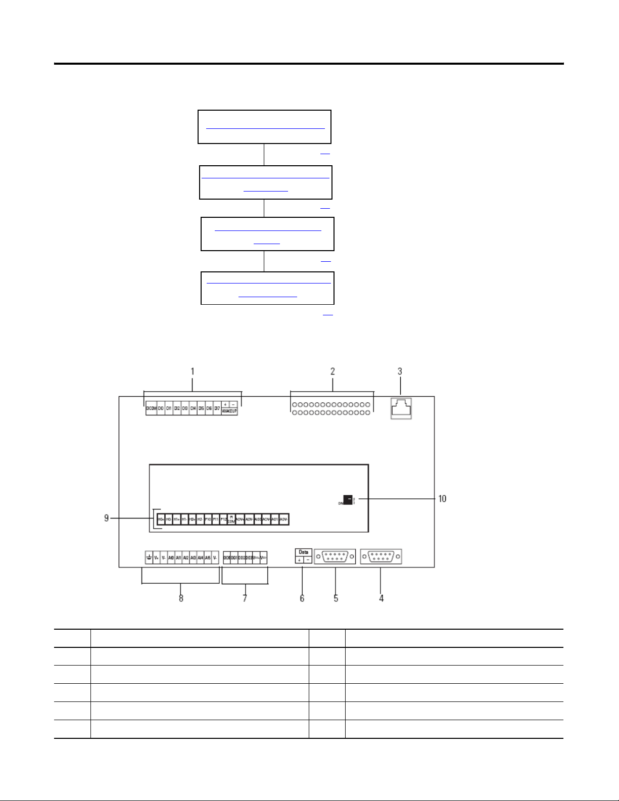
Review DataSite Connections
Item Description Item Description
1 Discrete inputs and wake-up connectors 6 RS-485 COM 1 connector
2 Status indicators 7 Discrete output connectors
3 Ethernet connector 8 Power input and analog input connectors
4 RS-232 COM 2 connector 9 HART, pulse input, and analog output connectors
5 RS-232 COM 1 connector 10 Pulse input filter switches
18 Publication IASIMP-QS008A-EN-P - March 2009
Page 19
System Layout and Wiring Chapter 2
Plan Your DataSite Panel Layout and Wiring
The DataSite Accelerator Toolkit CD includes AutoCAD Electrical project files that include panel
layout and wiring diagrams that you can easily modify for your specific application. Individual
DWG, DXF, and PDF files are available for use in standard AutoCAD and non-AutoCAD drawing
and image software packages. The drawings are designed to optimize panel space and minimize
electrical noise.
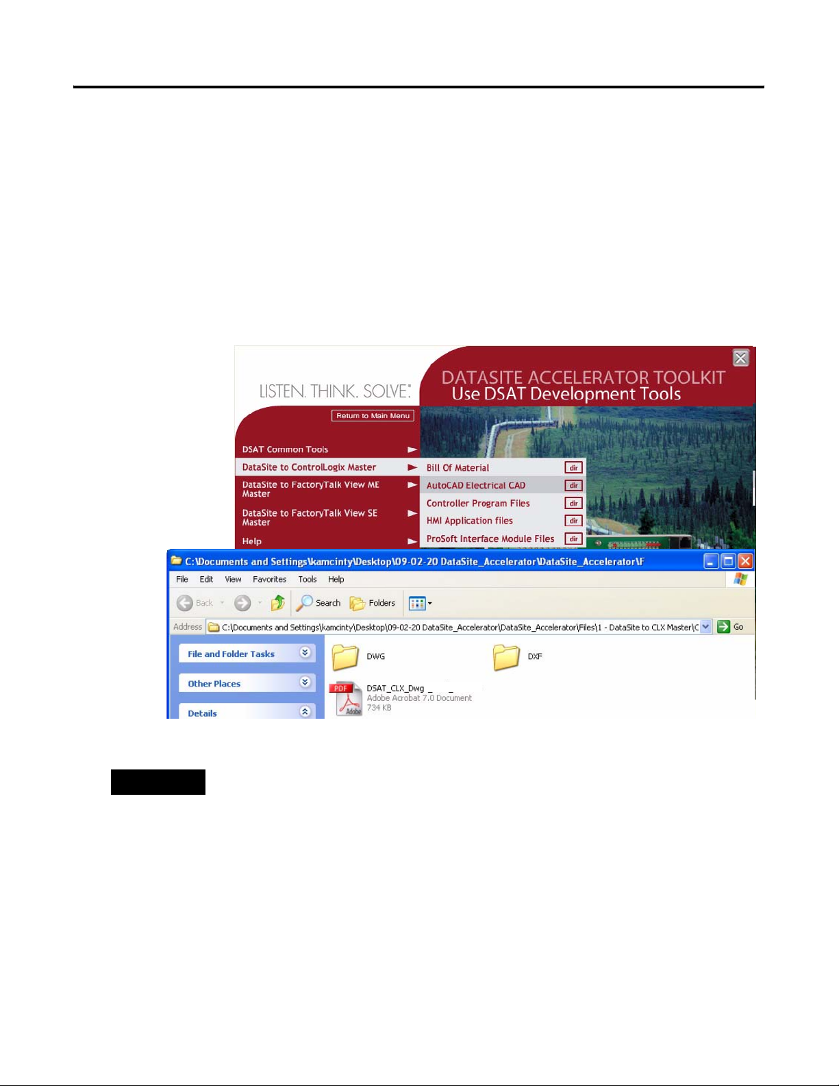
Follow these steps to load CAD files from the DataSite Accelerator Toolkit CD.
1. On the toolkit CD, select DataSite Development Tools.
2. Choose DataSite to ControlLogix Master>AutoCAD Electrical CAD.
3. Open the DWG or DXF folder.
TIP
The PDF file contains the same information as the individual DXF and DWG files. Use
Adobe Acrobat Reader to open the PDF file.
4. Use your CAD program to open the DWG or DXF files.
5. Identify additional layout needs specific to your application.
6. Repeat steps 2 - 5 to view the CAD files for the other two DataSite configurations.
• DataSite to FactoryTalk View ME Master>AutoCAD Electrical CAD
• DataSite to FactoryTalk View SE Master>AutoCAD Electrical CAD
Publication IASIMP-QS008A-EN-P - March 2009 19
Page 20
Chapter 2 System Layout and Wiring
Verifying Your Basic Panel Layout
The AutoCAD Electrical project includes panel layouts and wiring diagrams for each of the three
DataSite configurations. Add or remove components as needed.
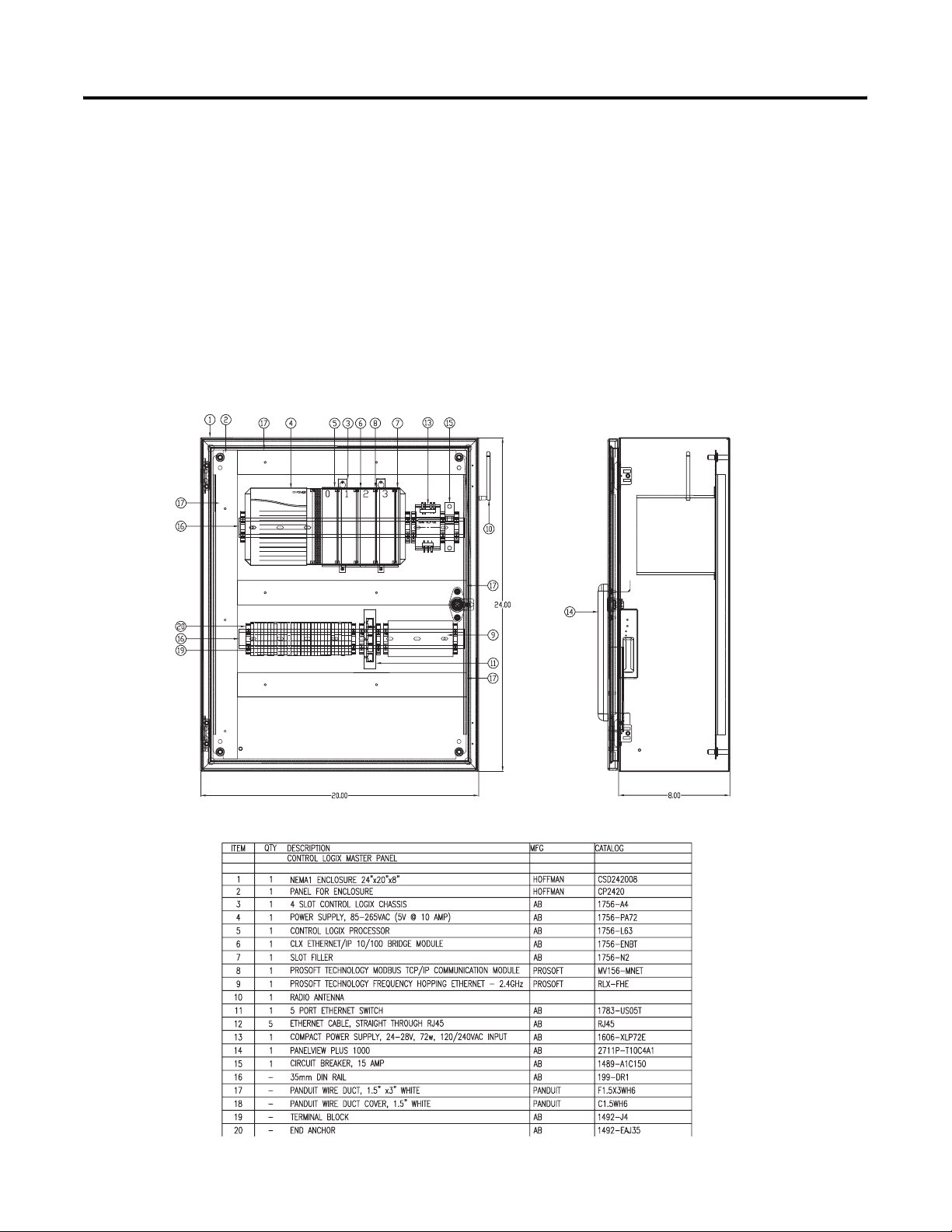
Panel Layouts for the DataSite to ControlLogix Master Configuration
The DataSite to ControlLogix Master configuration includes panel layouts for host and remote
locations. Refer to the bill of material below each layout to review the items in each panel.
Host DataSite Location - Panel Layout
Sample Bill of Material - Host DataSite Panel Layout
20 Publication IASIMP-QS008A-EN-P - March 2009
Page 21
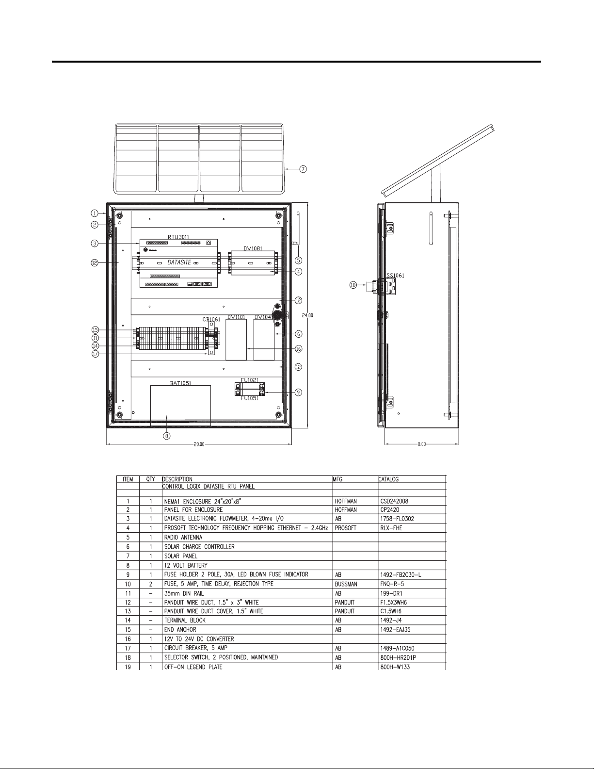
Remote DataSite Location - Panel Layout
System Layout and Wiring Chapter 2
Sample Bill of Material - Remote DataSite Location
Publication IASIMP-QS008A-EN-P - March 2009 21
Page 22
Chapter 2 System Layout and Wiring
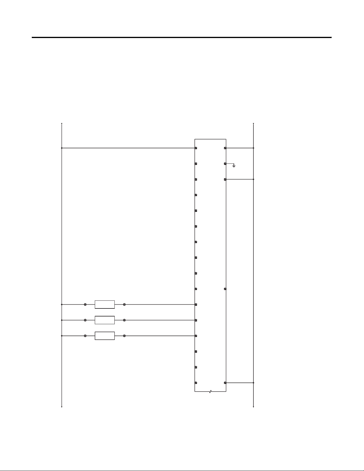
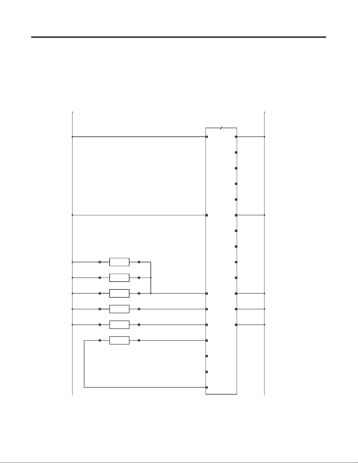
Wiring Diagrams for the DataSite to ControlLogix Master Configuration
The AutoCAD electrical project includes wiring diagrams for each of the three DataSite
configurations. The example shows power wiring for the DataSite to ControlLogix Master
configuration. Add or remove components as needed.
Sample CAD Wiring Diagram
1001 1002
from 117 from 117
300
301
+12VDC 12VCOM
DATASITE
RTU3011
1758-FLO302
2
V+
3
V-
302
303
304
305
306
307
308
1001 1002
309
310
DIFFERENTIAL PRESSURE
311
312
313
PS3111
3
+-
TB1
STATIC PRESSURE
PS3121
5
+-
TB1
TEMPERATURE
TS3131
7
+-
TB1
4
TB1
6
TB1
8
TB1
3111
3121
3131
20
DI0
21
DI1
22
DI2
23
DI3
24
DI4
25
DI5
26
DI6
27
DI7
28
+
4
AI0
5
AI1
6
AI2
DICOM
WAKE UP
GND
19
29
1
-
314
315
316
317
+12VDC
to 318
7
AI3
8
AI4
319
10
V-
12VCOM
to 318
9
AI5
1001 1002
22 Publication IASIMP-QS008A-EN-P - March 2009
Page 23
System Layout and Wiring Chapter 2
318
319
320
321
322
323
324
325
326
327
328
329
330
331
332
1001
from 317 from 317
+12VDC 12VCOM
DATASITE
RTU3011
1001
HART DEVICE 1
SW3271
9
+-
TB1
HART DEVICE 2
SW3281
11
+-
TB1
HART DEVICE 3
SW3291
13
+-
TB1
HART DEVICE 4
SW3301
15
+-
TB1
HART DEVICE 5
SW3311
17
+-
TB1
PULSE INPUT
SW3321
19
- +
TB1
1758-FLO302
VDO+
40
AOV+
10
TB1
12
TB1
14
TB1
16
TB1
18
TB1
20
TB1
3271
3301
3311
3321
30
H0+
32
H1+
34
H2+
36
PI0
VDO-
DO0
DO1
DO2
DO3
AOV-
AO0
AOV-
AO1
AOV-
H0-
H1-
H2-
1615
11
12
13
14
41
42
43
1002
44
45
31
33
35
1002
333
334
335
3322
37
PI1
38
PI2
39
PICOM
Publication IASIMP-QS008A-EN-P - March 2009 23
Page 24
Chapter 2 System Layout and Wiring
Download Other Allen-Bradley CAD Drawings
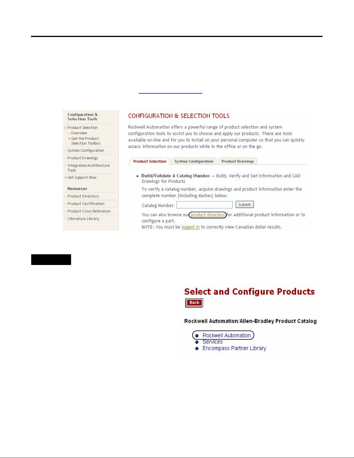
Follow these steps to download other Allen-Bradley product CAD drawings.
1. Open your browser and go to http://ab.com/e-tools.
The Configuration and Selection tools web page opens.
TIP
If you know the complete catalog number of your Allen-Bradley product, you can enter it here and click
Submit. However, you need a complete catalog number string to get the configuration results.
2. If you don’t know the complete catalog
number, click product directory to
browse the configured Rockwell
Automation products.
3. Click Rockwell Automation and follow
the prompts.
24 Publication IASIMP-QS008A-EN-P - March 2009
Page 25

Chapter
3
DataSite and Logix Integration
Introduction
In this chapter, you configure the DataSite unit, download the ControlLogix user program,
configure the ProSoft (MVI56-MNET) Modbus TCP/IP communication module, and connect all
system devices.
Before You Begin
• Complete your system hardware selection (Chapter 1).
• Complete your system layout and wiring (Chapter 2).
• Load all DataSite software on your computer as listed in the Preface on page 10. In this
chapter, you will use the DS FloConfig and RSLogix 5000 software.
• Assign IP addresses to all devices on network. The table lists IP addresses used in this
quick start.
Device IP Address Device IP Address
1756-ENBT Ethernet module 192.168.10.90 ProSoft MV156-MNET module 192.168.10.94
Master radio 192.168.10.91 Personal computer 192.168.10.95
Remote radio 192.168.10.92 PanelView Plus 1000 terminal 192.168.10.96
DataSite unit 192.168.10.93
This chapter assigns IP addresses to the 1756-ENBT Ethernet module, the DataSite unit, and
the Prosoft MV156-MNET module. For details on how to assign an IP address to the
PanelView Plus terminal, refer to the PanelView Plus Terminals User Manual, publication
2711P-UM001
. For the other devices, refer to the manufacturer’s user manual.
What You Need
• Personal computer or laptop
• Hardware:
– 1758-FLOxxx DataSite Unit
– 1756-L63 ControlLogix controller
– 1756-ENBT EtherNet/IP module
25Publication IASIMP-QS008A-EN-P - March 2009 25
Page 26
Chapter 3 DataSite and Logix Integration
– Modbus TCP/IP communication module (MV156-MNET) from ProSoft Technology
– PanelView Plus 1000 terminal
– Two Ethernet RF radios
– 1747-CP3 null-modem serial cable
– One Ethernet crossover cable
– Five Ethernet straight-through cables
– Ethernet switch
• Software:
– DS FloConfig software
– RSLogix 1000 software
– DataSite Accelerator Toolkit CD, publication IASIMP-SP011
Follow These Steps
Configure the DataSite Unit
page 27
Configuring the Logix Controller
Load and Open the Logix
Application File
page 31
Configure the ControlLogix
Controller Properties
page 32
Configure ControlLogix
Communication
page 33
Save and Download Your
Program
Configure the ProSoft Modbus
Module
page 36
Connecting All Devices
page 42
page 34
26 Publication IASIMP-QS008A-EN-P - March 2009
Page 27
DataSite and Logix Integration Chapter 3
Configure the DataSite Unit
The communication parameters for the DataSite unit are configured using DS FloConfig software.
The DataSite unit can communicate using either its serial or Ethernet port. This quick start uses
the serial port to assign the DataSite unit an IP address of 192.168.10.93 and then changes to
Ethernet communication.
TIP
Make sure your computer or laptop is assigned an IP address where the first three octets are the same as
the DataSite unit, 192.168.10.XX. In this quick start, the computer uses a static IP address of
192.168.10.95 with a subnet mask of 255.255.255.0.
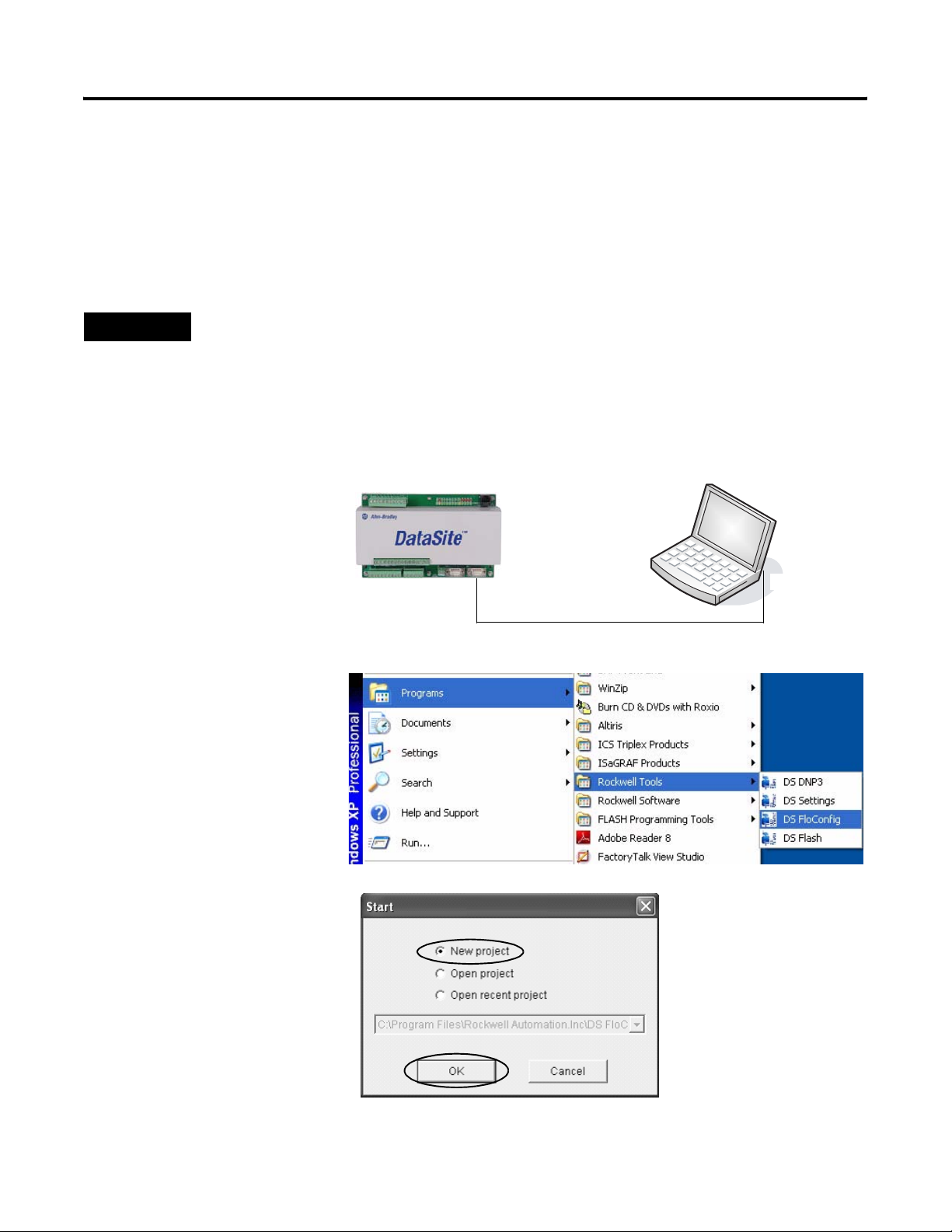
Follow these steps to assign an IP address, 192.168.10.93, and configure Ethernet communication
for the DataSite unit.
1. Connect a 1747-CP3
192.168.10.93
192.168.10.95
(null-modem) serial cable
between your computer's
serial port and the COM2
port on the DataSite unit.
COM2 Serial Port
Serial Port
2. Apply 12V DC power to
the DataSite unit.
1747-CP3 Null-modem Serial Cable
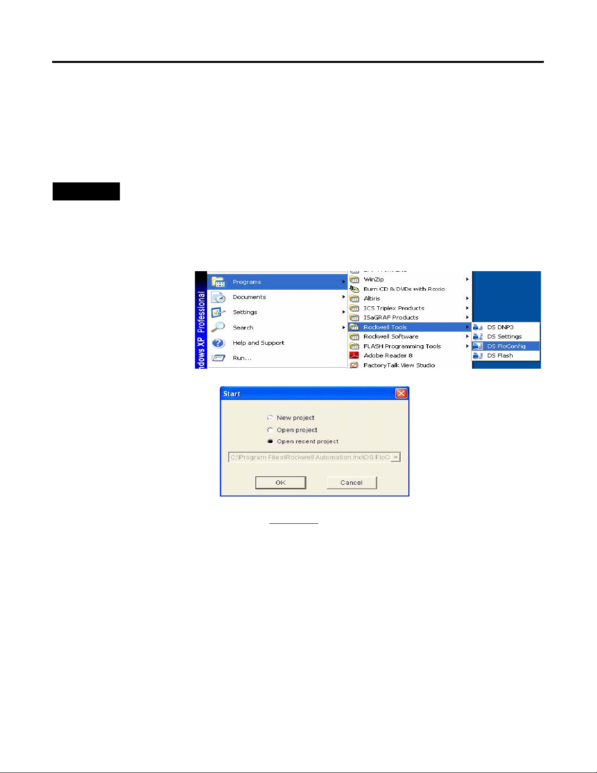
3. Launch the DS FloConfig
software.
The path shown may be
different on your
computer depending on
where the software is
installed.
4. Select New Project and
click OK.
Publication IASIMP-QS008A-EN-P - March 2009 27
Page 28
Chapter 3 DataSite and Logix Integration
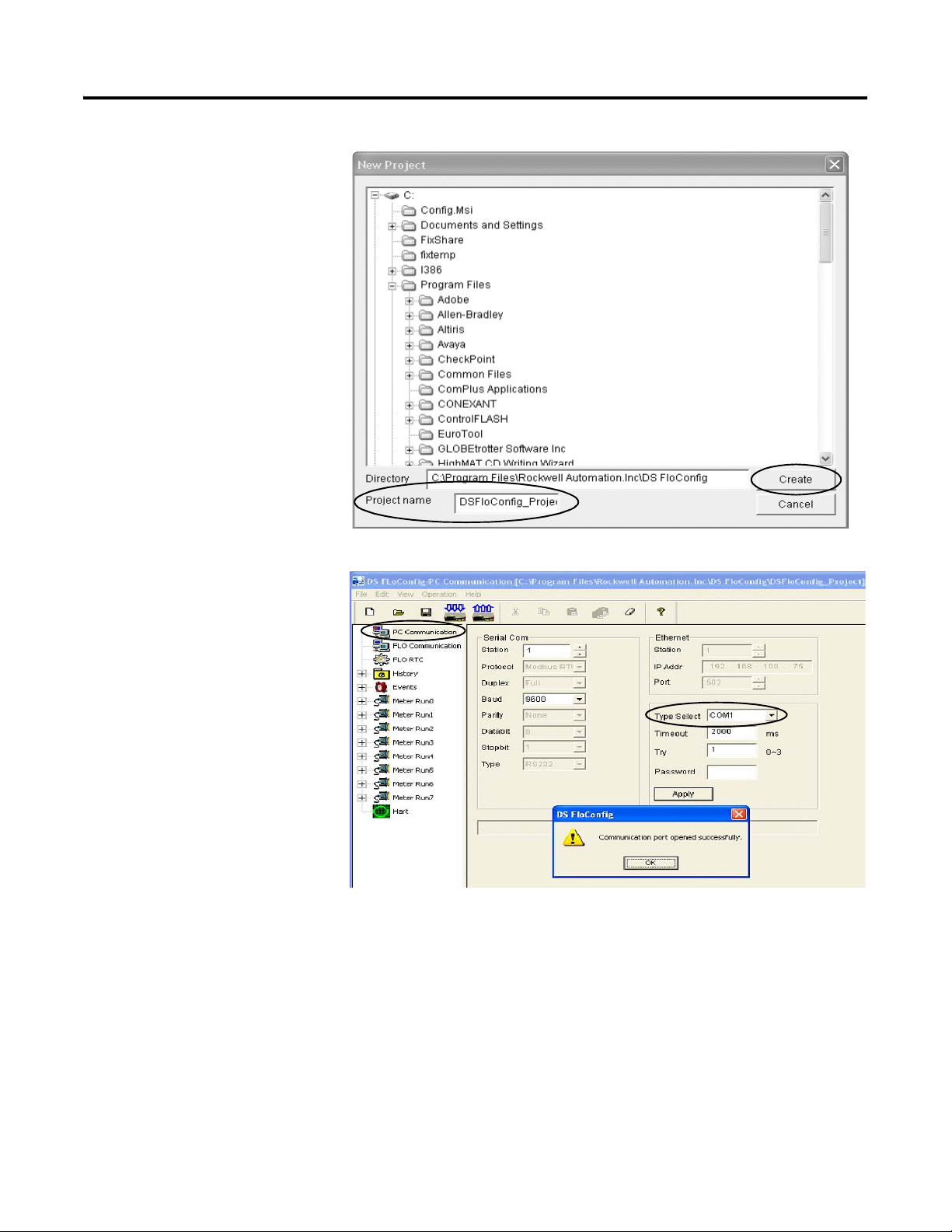
5. Create a new project.
a. Enter a project name.
b. Enter the directory
where you want to
store the project.
This examples saves the
project in the default
directory.
c. Click Create.
6. Click PC Communication.
a. Select COM1 from the
Type Select pull-down
list.
b. Click Apply.
A message informs you
that the Communication
port opened successfully.
c. Click OK.
28 Publication IASIMP-QS008A-EN-P - March 2009
Page 29
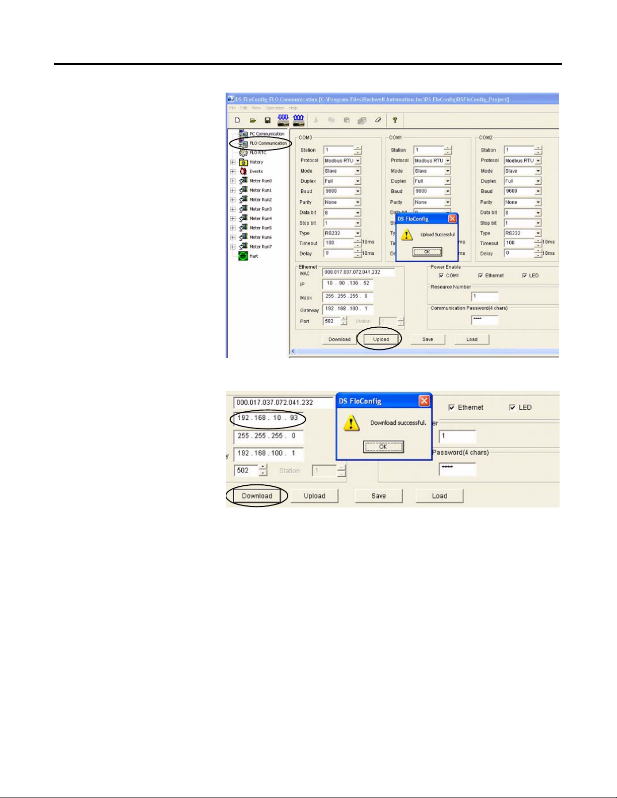
7. Click Flo Communication,
then click Upload.
The screen refreshes with
the existing IP address
and serial port settings.
8. Click OK when you see
Upload Successful.
DataSite and Logix Integration Chapter 3
9. Under Ethernet:
a. Type the IP address for
the DataSite unit.
This example uses
192.168.10.93.
b. Click Download.
c. Click OK when you see
the Download
successful message.
10. Cycle power to the
DataSite unit.
You must power cycle
when changing the IP
address.
Publication IASIMP-QS008A-EN-P - March 2009 29
Page 30
Chapter 3 DataSite and Logix Integration
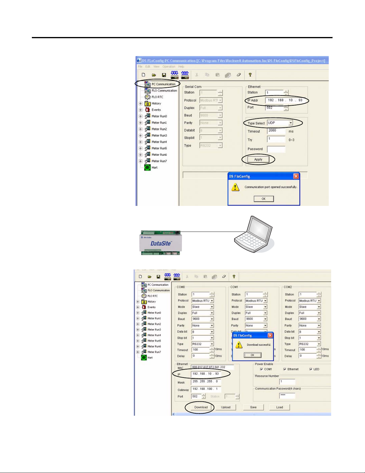
11. Click PC Communication.
a. Select UDP or
TCP/Server from the
Type Select pull-down
list.
b. Type the IP address,
192.168.10.93 that you
just downloaded to the
DataSite unit.
c. Click Apply.
d. Click OK when you see
Communication port
opened successfully.
12. Connect your computer
to the DataSite unit using
an Ethernet crossover
cable.
13. Click Flo Communication.
a. Verify the IP address is
192.168.10.93.
b. Click Download.
c. Click OK when you see
the Download
successful message.
Ethernet Crossover Cable
The IP address of the DataSite unit was set successfully and now uses Ethernet communication.
30 Publication IASIMP-QS008A-EN-P - March 2009
Page 31
DataSite and Logix Integration Chapter 3
Configuring the Logix Controller
The sample Logix program on the DataSite Accelerator Toolkit CD provides the logic necessary to
manipulate data coming from the Modbus TCP/IP communication module and makes it available
to the ControlLogix L63 controller tags.
Load and Open the Logix Application File
Follow these steps to load and open the (.acd) Logix application file from the DataSite
Accelerator Toolkit CD.
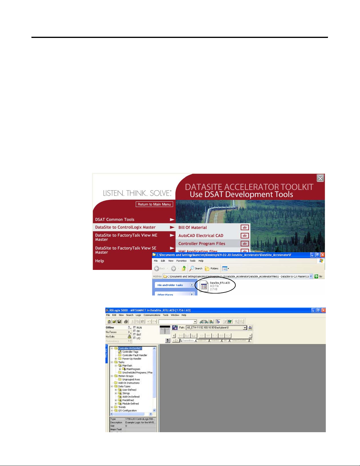
1. On the toolkit CD, choose DataSite to ControlLogix Master>Controller Program Files, then
double-click the DataSite_RTU.ACD application file.
The RSLogix 5000
software
launches and
opens the.acd
file.
Publication IASIMP-QS008A-EN-P - March 2009 31
Page 32
Chapter 3 DataSite and Logix Integration
Configure the ControlLogix Controller Properties
Follow these steps to configure your ControlLogix L63 controller.
1. Apply power to your
ControlLogix chassis.
2. Connect your computer
and 1756-ENBT Ethernet
module to the Ethernet
switch using Ethernet
straight-through cables.
3. Choose Controller
Properties from the Edit
menu to open the
Controller Properties
dialog box.
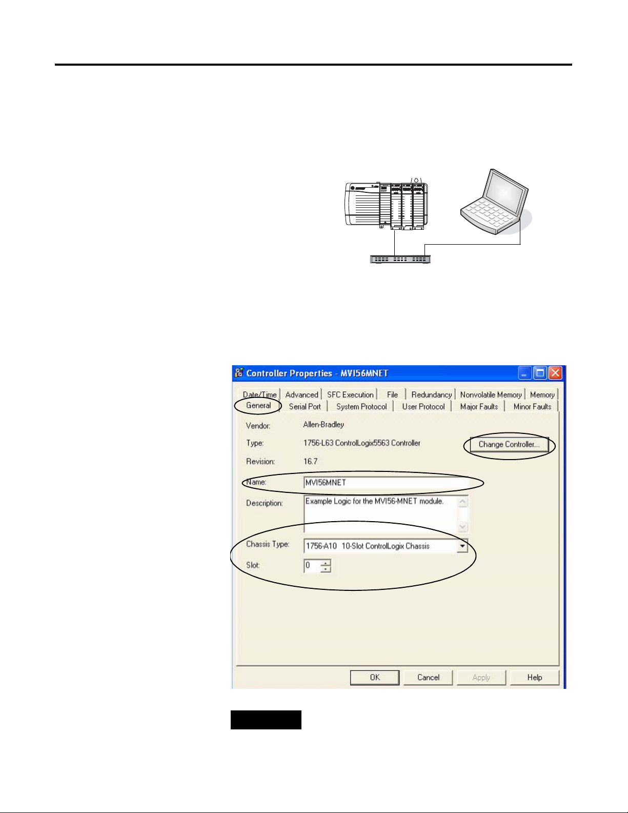
4. Click the General tab.
a. Click the Change
Controller button to
select the controller
that matches your
hardware.
This example uses
1756-L63 revision 16.
1756-L63 ControlLogix Controller
with 1756-ENBT Ethernet/IP Module
ENBT Module
192.168.10.90
Ethernet Straight-through Cables
Ethernet Switch
192.168.10.95
ENBT
ProSoft
b. Change the controller
Name as desired.
c. From the Chassis Type
pull-down list, select
the catalog number for
your chassis.
d. Set the slot number to
0 to indicate the
1756-L63 controller
resides in slot 0.
e. Click OK.
TIP
32 Publication IASIMP-QS008A-EN-P - March 2009
Slot 0 is reserved for the 1756-L63 module. Slot 1 is reserved
for the 1756-ENBT module. Slot 2 is reserved for the ProSoft
Modbus TCP/IP module.
Page 33
DataSite and Logix Integration Chapter 3
Configure ControlLogix Communication
This procedure assumes that communication to the Logix controller is using the Ethernet port. It
also assumes that your 1756-ENBT Ethernet/IP module has already been configured with an IP
address of 192.168.10.90.
For additional information, refer to the ControlLogix Controllers User Manual, publication
1756-UM051.
Follow these steps to configure ControlLogix communication.
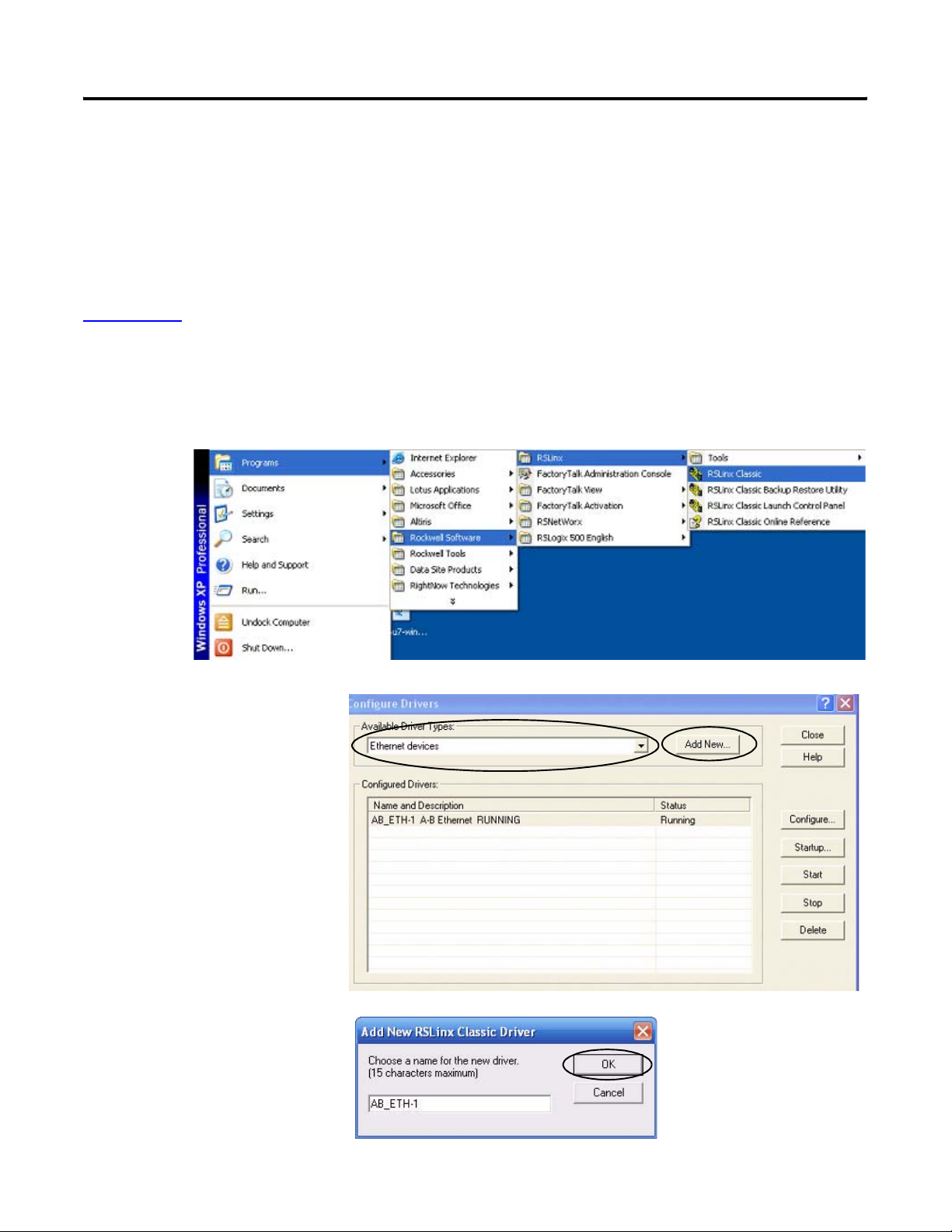
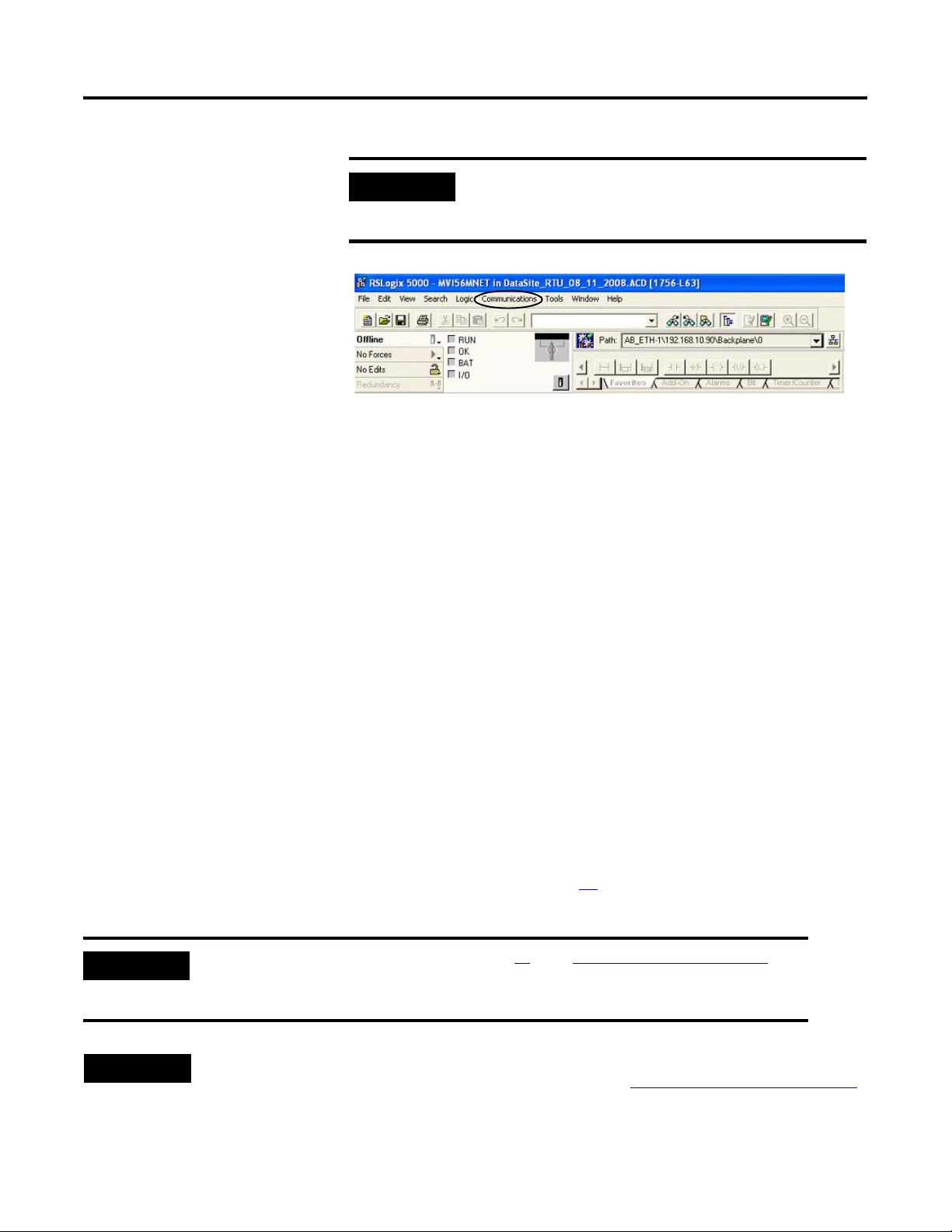
1. Open the RSLinx Classic software, then choose Configure Drivers... from the
Communications menu.
The Configure Drivers
Window opens.
2. Select Ethernet devices
from the pull-down list.
3. Click the Add New
button.
4. Accept the default driver
name, AB_ETH-1, or
change the name and
click OK.
Publication IASIMP-QS008A-EN-P - March 2009 33
Page 34
Chapter 3 DataSite and Logix Integration
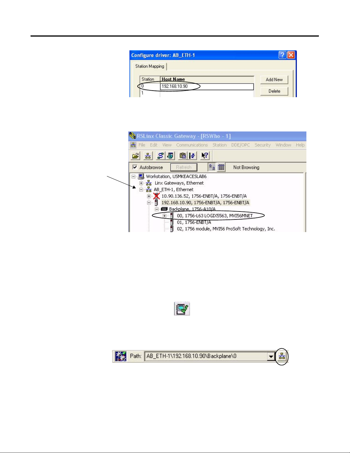
5. Enter the IP address of
your Ethernet ENBT
module and click OK.
This example uses
192.168.10.90.
6. Click Close to close the Configure Drivers window.
7. Choose RSWho from the
Communications menu.
The RSWho window
opens.
8. Expand AB_ETH_1,
Ethernet until your
1756-L63 Logix controller
is visible.
9. Verify that you can
browse to your Logix
controller in slot 0.
10. Minimize the RSLinx window and return to your RSLogix 5000 project window.
Save and Download Your Program
Follow these steps to save your program and download it to the ControlLogix controller.
1. Click Verify Controller on the RSLogix
5000 toolbar to verify the Logix program.
If any errors or warnings occur, they display at the bottom of the window.
2. Choose Save from the File menu to save the program.
3. Click Who Active.
34 Publication IASIMP-QS008A-EN-P - March 2009
Page 35
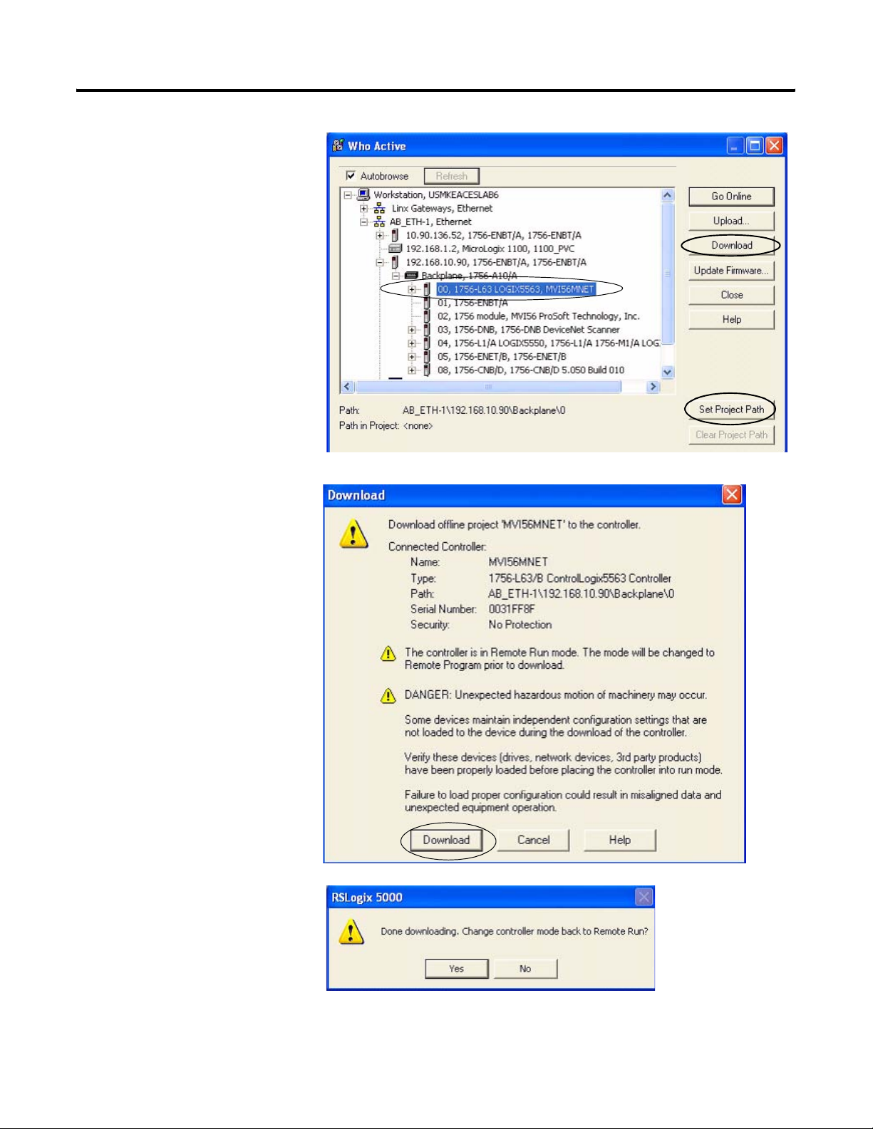
4. Browse to the 1756-L63
controller and click the
Set Project Path button.
5. Verify that the key switch
on the controller is in the
REM (remote) position.
6. Click Download.
The Download window
opens.
DataSite and Logix Integration Chapter 3
7. Click Download to send
the program to the
1756-L63 controller.
8. Click No when the
download is complete.
Publication IASIMP-QS008A-EN-P - March 2009 35
Page 36
Chapter 3 DataSite and Logix Integration
IMPORTANT
All system devices must be configured and connected before
placing the controller in Run mode. If the controller is already in
Run mode, choose Offline from the Communications menu.
Configure the ProSoft Modbus Module
The ProSoft MV156-MNET Modbus TCP/IP communication module polls the Modbus registers of
the DataSite unit and makes the data available to the 1756-L63 controller tags. The Prosoft module
slides into slot 2 of the ControlLogix chassis and requires two configuration (.cfg) files to operate.
• WATTCP.CFG assigns an IP address to the ProSoft MVI56-MNET module.
• MNET.CFG defines the list of Modbus registers to read from or write to the DataSite unit.
You will download these configuration files from the DataSite Accelerator Toolkit CD.
The WATTCP.CFG file was modified to assign the ProSoft MVI56-MNET module an IP Address of
192.168.10.94. The MNET.CFG file was modified to poll 19 DataSite natural gas Modbus registers
from each of the 8 meter runs which will display on a PanelView Plus 1000 terminal.
If necessary, you can use Notepad to open and modify the configuration files. For more
information on these files and how they were created, refer to the MVI56-MNET User Manual in
the DSAT Common Tools>Literature and Support Info>ProSoft directory of the Accelerator Toolkit
CD. In addition to the configuration files, a (.acd) Logix program is required to manipulate the
Modbus data written to the L63 controller tags. Refer to page 31
for details on how to download
the Logix program.
IMPORTANT
TIP
The.acd Logix program was downloaded on page 31 in the Configuring the Logix Controller
section. You must download the Logix program to the ControlLogix L63 controller before you
configure the Prosoft Modbus module.
For technical support on the Prosoft MVI56-MNET module, email support@prosoft-technology.com or call
the technical support number 1 + (661) 716-5100 that is available at http://www.prosoft-technology.com/
36 Publication IASIMP-QS008A-EN-P - March 2009
Page 37
DataSite and Logix Integration Chapter 3
Follow these steps to download the WATTCP.CFG and MNET.CFG configuration files from the
DataSite Accelerator Toolkit CD to the ProSoft Modbus module.
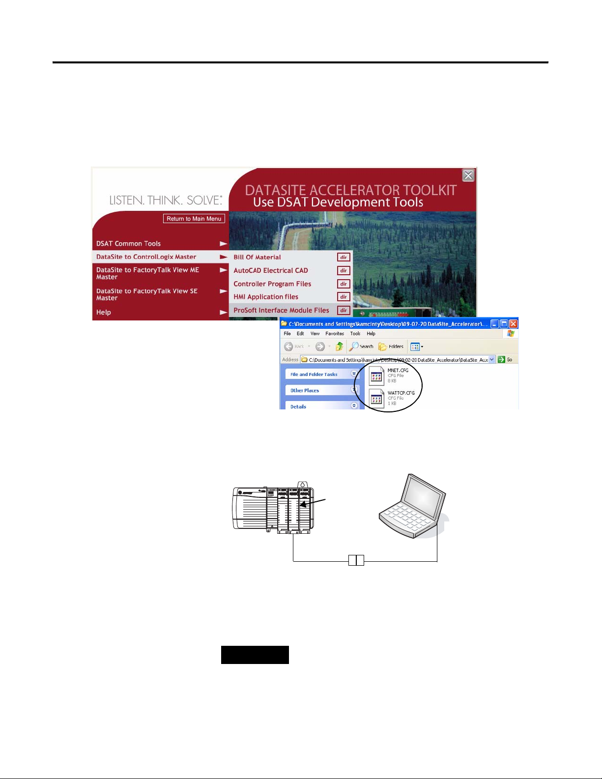
1. On the toolkit CD, choose DataSite to ControlLogix Master>ProSoft Interface Module Files,
then copy the files MNET.CFG and WATTCP.CFG to your desktop.
2. Install the ProSoft
Modbus module into slot
2 of the Logic chassis.
Slot 2 is used in this quick
start. If you change the
slot number, then you
must modify the .acd
Logix program.
3. Apply power to the
chassis.
4. Connect the serial cable
that ships with the ProSoft
module between the
serial port on your
computer and the (RJ45)
CFG port on the ProSoft
module.
ProSoft Module, Slot 2
192.168.90.94
ENBT
ProSoft
To CFG
(RJ45) Port
TIP
Disconnect the serial cable that you previously used to connect
your computer to the DataSite unit.
192.168.10.95
Slot 2
To Serial COM Port
Cable Shipped with ProSoft Module
Publication IASIMP-QS008A-EN-P - March 2009 37
Page 38
Chapter 3 DataSite and Logix Integration
5. Choose Start>Programs>Accessories>Communications>HyperTerminal to open the hyper
terminal on your desktop.
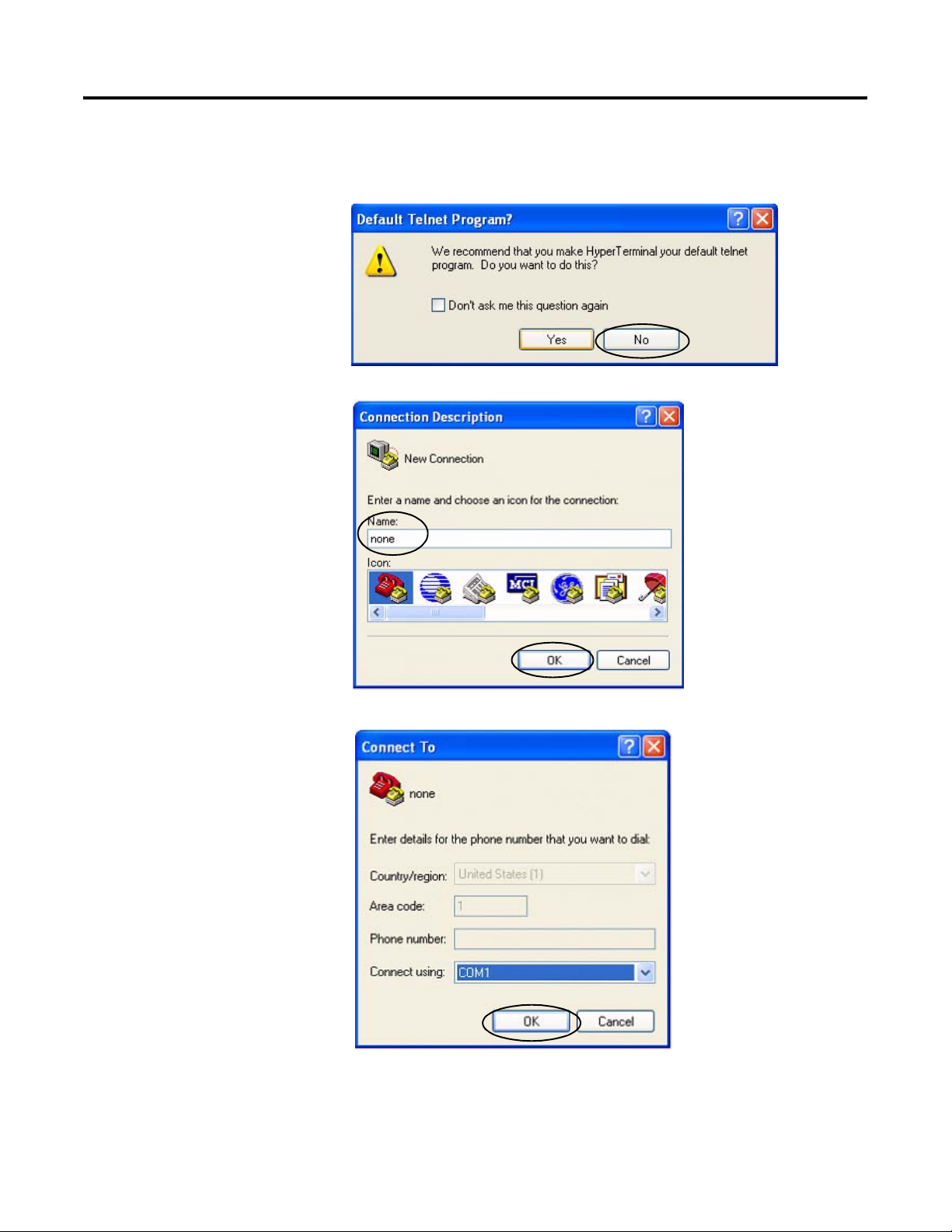
6. Click No if you see this
dialog box.
7. Enter a name for the new
connection and click OK.
8. Select the COM port used
by your computer and
click OK.
This example uses COM1.
38 Publication IASIMP-QS008A-EN-P - March 2009
Page 39
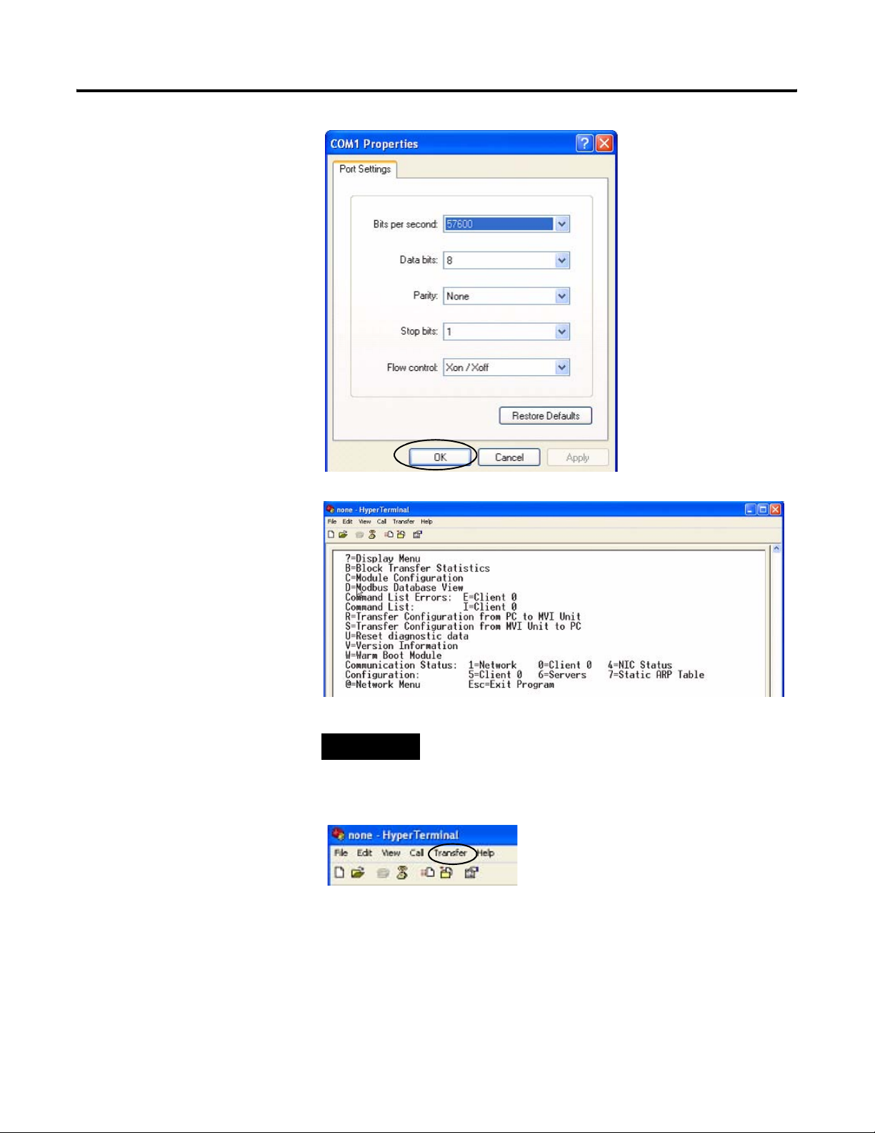
9. Set the COM1 port
settings as shown and
click OK.
DataSite and Logix Integration Chapter 3
10. Press Shift+? to display
the MVI56-MNET menu.
11. Press R, then press Y to
transfer the MNET.CFG
file.
12. From the Transfer menu,
choose Send File.
TIP
After pressing Y, you have limited time to browse for
the file before a timeout occurs.
Publication IASIMP-QS008A-EN-P - March 2009 39
Page 40
Chapter 3 DataSite and Logix Integration
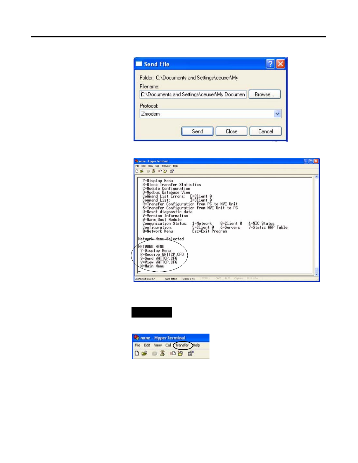
13. From the Send File dialog
box:
a. Click Browse to locate
MNET.CFG, then click
Open.
b. Select Zmodem from
the Protocol list.
c. Press Send.
A progress bar shows the
status of the file transfer.
14. Press Shift+? to return to
the main menu.
15. Press Shift+@, then
Shift+? to display the
Network menu.
16. Press R, then Y to transfer
WATTCP.CFG.
17. From the Transfer menu,
choose Send File.
TIP
After pressing Y, you have limited time to browse for the file
before a timeout occurs.
40 Publication IASIMP-QS008A-EN-P - March 2009
Page 41
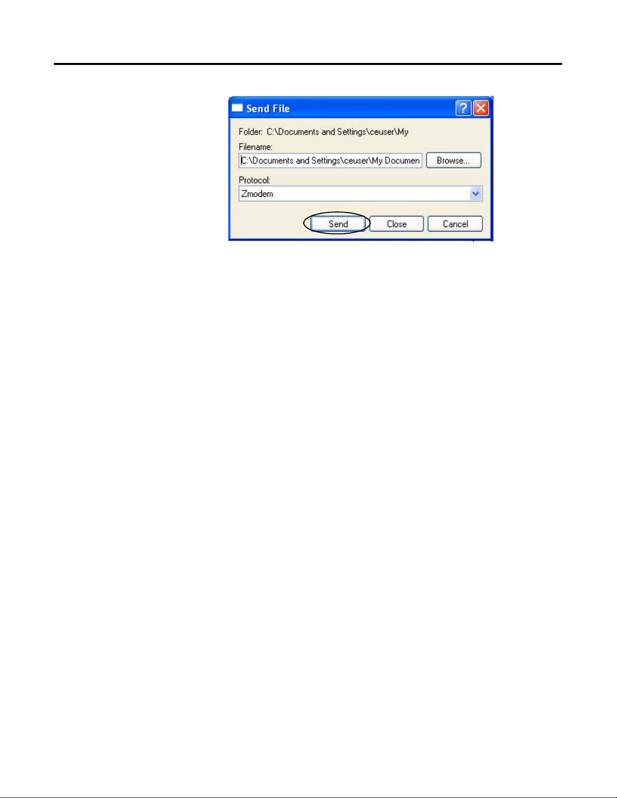
18. From the Send File dialog
box:
a. Click Browse to locate
WATTCP.CFG, then
click Open.
b. Select Zmodem from
the Protocol list.
c. Press Send.
A progress bar shows the
status of the transfer.
19. Press Shift+? to display
the Network menu; then
press M followed by
Shift+? to return the main
menu.
DataSite and Logix Integration Chapter 3
The ProSoft Modbus
module is now
configured.
20. Close the HyperTerminal
dialog box.
21. Cycle power to the
ProSoft module by
pulling it from the chassis
and re-inserting it.
This registers the new IP
address.
Publication IASIMP-QS008A-EN-P - March 2009 41
Page 42

Chapter 3 DataSite and Logix Integration
Connecting All Devices
At this point all devices should be connected as shown in the illustration. Modify any previous
connections, if necessary, to match the illustration.
Remote Location
Ethernet
1758-FLO302 Datasite
Radio
2711P-CBL-EX04
Crossover Cable
Host Location
1756-L63 ControlLogix Controller
with 1756-ENBT Ethernet/IP and ProSoft Module
Chassis
ProSoft
ENBT
L63
Ethernet Switch
2711P PanelView Plus 1000 Terminal
with Built-in Ethernet Port
All devices connect to Ethernet switch using Ethernet straight-through cables.
Laptop
Radio
You must use an Ethernet crossover cable to connect the DataSite unit to the radio. The cable
between the Ethernet switch and the ProSoft MVI56-MNET Modbus module must connect to the
RJ45 Ethernet Port; not the CFG port.
The configuration of the Ethernet radio modems is not covered in this quick start. Refer to your
radio user manual for instructions on how to configure and assign IP addresses to both radios.
After wiring is complete, apply power to all devices.
TIP
42 Publication IASIMP-QS008A-EN-P - March 2009
Radios are optional. If your application does not require radios simply replace the radios
with an Ethernet straight-through cable connecting the DataSite to the Ethernet switch.
Page 43

Chapter
4
DataSite Workbench and Screen Builder Integration
Introduction
In this chapter, you download the DataSite Workbench sample user program and DataSite Screen
Builder sample web pages to the DataSite unit.
Before You Begin
• Complete your system hardware selection (Chapter 1).
• Complete your system layout and wiring (Chapter 2).
• Complete the DataSite and Logix Integration (Chapter 3).
• Verify that all devices are connected properly and are powered up.
What You Need
• Personal computer
• All system devices properly connected and powered up
• Hardware: DataSite unit
• Software:
– DataSite Workbench 5.2
– DataSite Screen Builder 1.3
– DataSite Accelerator Toolkit CD, publication IASIMP-SP011
43Publication IASIMP-QS008A-EN-P - March 2009 43
Page 44

Chapter 4 DataSite Workbench and Screen Builder Integration
Follow These Steps
Download the DataSite User
Program
Download the DataSite
Web Pages
page 45
page 49
44 Publication IASIMP-QS008A-EN-P - March 2009
Page 45

DataSite Workbench and Screen Builder Integration Chapter 4
Download the DataSite User Program
Follow these steps to compile and download the sample DataSite user program.
1. Launch DataSite Workbench 5.2 software.
2. From the Project/Library
menu, choose Open.
3. Select the Prj folder from the
Look in: pull-down list.
4. Double-click the folder
DataSite_Base_Program.
If you don’t see this dialog
box, refer to the tip.
TIP
If you don’t see the DataSite_Base_Program folder in step 4, follow these steps.
• From the DataSite Accelerator Toolkit CD, browse to DSAT Common Tools>DataSite User Programs.
• Copy and paste the DataSite_Base_Program folder to the DataSite Workbench default project directory:
C:\Documents and Settings\All Users\Documents\DataSite\Projects\Workbench 5.2\prj or
C:\Documents and Settings\All Users\Shared Documents\DataSite\Projects\Workbench 5.2\prj
• Now return to step 2 to open the project.
Publication IASIMP-QS008A-EN-P - March 2009 45
Page 46

Chapter 4 DataSite Workbench and Screen Builder Integration
5. Double-click PrjLibary.mdb to open the user program.
6. Click the Hardware
Architecture button.
7. Double-click the Vertical Network Bar, then enter the IP address of the DataSite unit and
click OK.
46 Publication IASIMP-QS008A-EN-P - March 2009
Page 47

8. Click the Link Architecture button.
9. Click Rebuild Project/Library.
10. Verify there are no errors.
DataSite Workbench and Screen Builder Integration Chapter 4
11. Click the Download button to download the program to the DataSite unit.
12. Click Select All, then click
Download.
Publication IASIMP-QS008A-EN-P - March 2009 47
Page 48
Chapter 4 DataSite Workbench and Screen Builder Integration
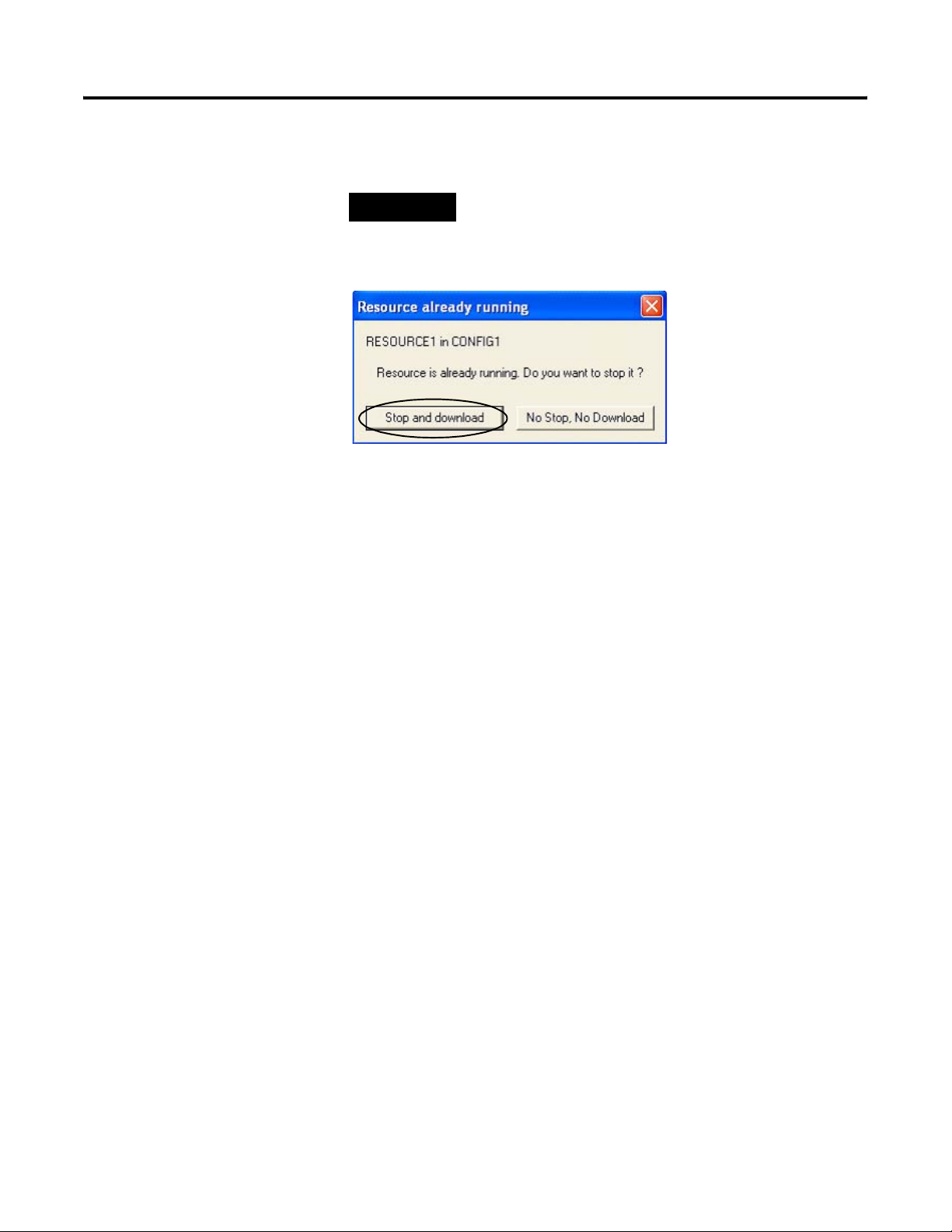
TIP
If the DataSite unit is running a program, you will see a
message similar to the one below. Click Stop and Download to
complete the Download process.
The DataSite Workbench user program has been downloaded and is running on the DataSite unit.
48 Publication IASIMP-QS008A-EN-P - March 2009
Page 49
DataSite Workbench and Screen Builder Integration Chapter 4
Download the DataSite Web Pages
You will now compile and download the sample DataSite web pages to the DataSite unit.
Follow these steps to download the HiBeam web pages.
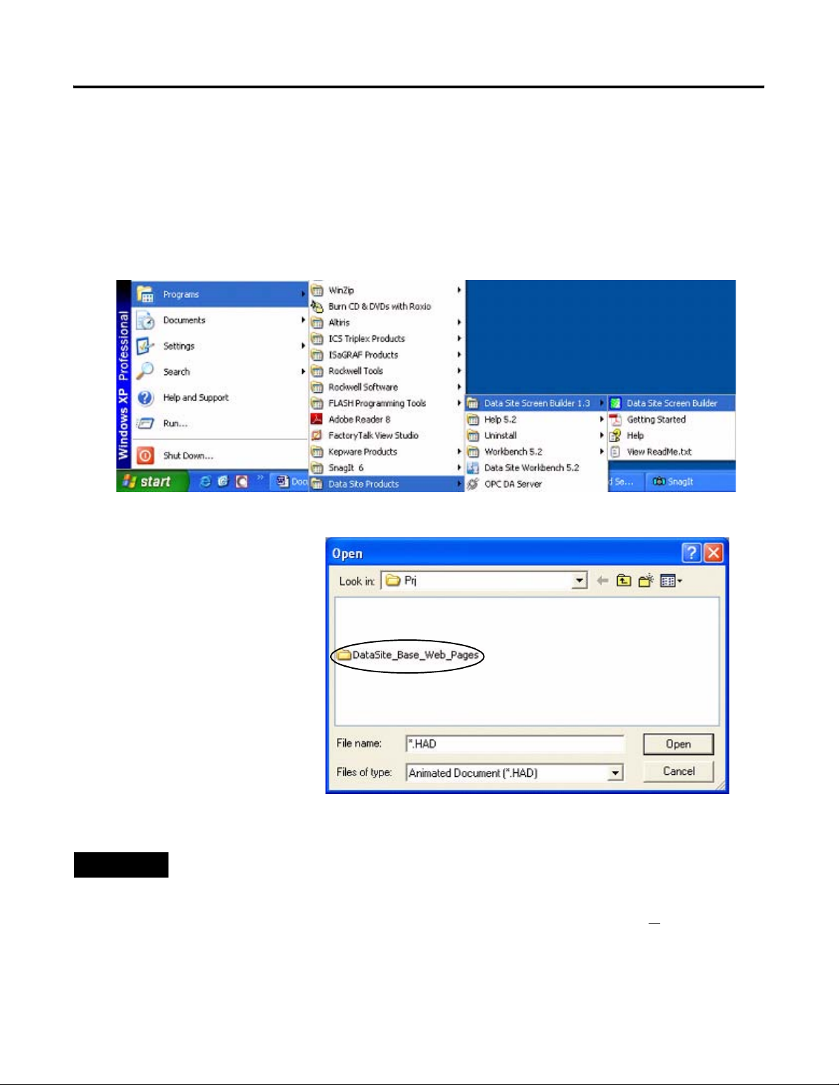
1. Launch the DataSite Screen Builder 1.3 software.
2. From the File menu, choose
Open.
3. Select the Prj folder from
the Look in: pull-down list.
4. Double-click the folder
DataSite_Base_Web_Pages.
If you don’t see this dialog
box, refer to the tip.
TIP
If you don’t see the DataSite_Base_Web_Pages folder in step 4, follow these steps.
• From the DataSite Accelerator Toolkit CD, browse to DSAT Common Tools>DataSite Web Pages.
• Copy and paste the DataSite_Base_Web_Pages folder to the DataSite ScreenBuilder default project directory:
C:\Documents and Settings\All Users\Documents\DataSite\Projects\ScreenBuilder 1.3\prj or
C:\Documents and Settings\All Users\Shared Documents\DataSite\Projects\ScreenBuilder 1.3\prj
• Now return to step 2 to open the project.
Publication IASIMP-QS008A-EN-P - March 2009 49
Page 50
Chapter 4 DataSite Workbench and Screen Builder Integration
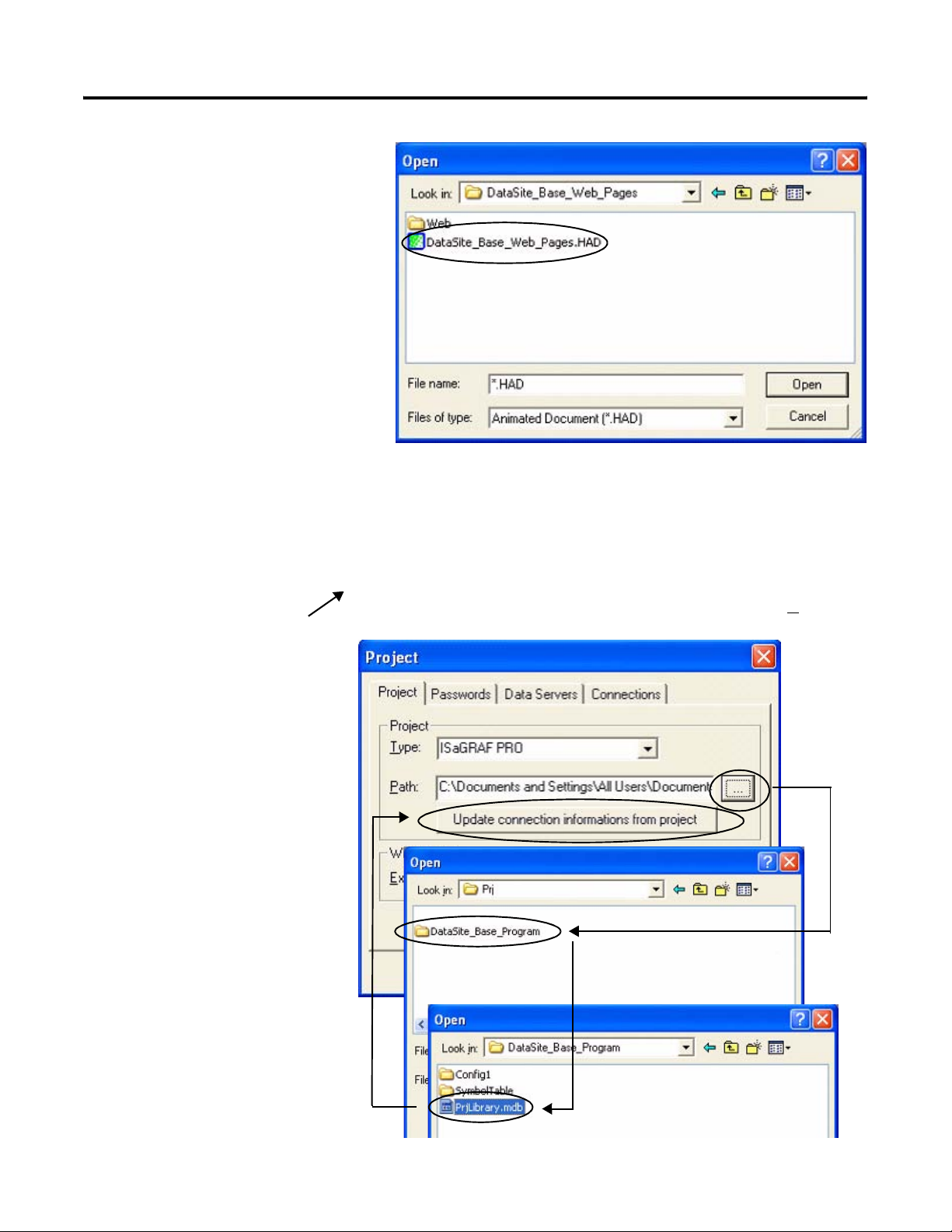
5. Double-click
DataSite_Base_Web_Pages.HAD
to open the web page program.
6. From the toolbar, choose
Project>Settings.
7. On the Project tab, click
the Path browse button.
8. Browse to the DataSite
Workbench default
project directory.
9. Double-click the
DataSite_Base_Program
folder.
10. Double-click
PrjLibrary.mdb, then click
Update connection
informations from project
button.
This allows the DataSite
web pages to access
variables created in the
sample DataSite
Workbench user program.
Default DataSite Workbench project directory:
C:\Documents and Settings\All Users\Documents\DataSite\Projects\Workbench 5.2\Prj or
C:\Documents and Settings\All Users\Shared Documents\DataSite\Projects\Workbench 5.2\Prj
Step 8
Step 9
Step 10
50 Publication IASIMP-QS008A-EN-P - March 2009
Page 51
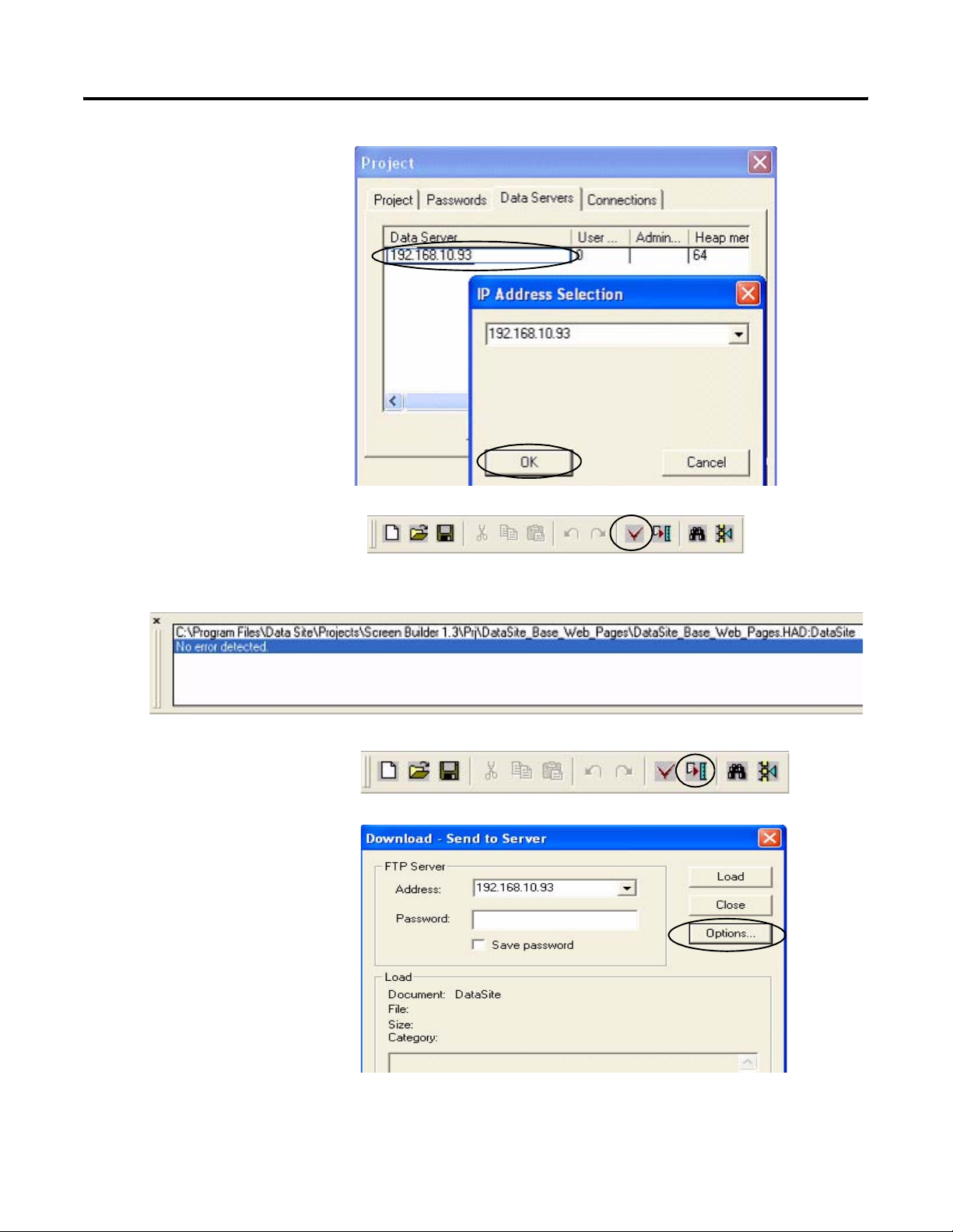
11. Click the Data Servers tab.
a. Double-click the row to
select the IP address of
the DataSite unit.
b. Click OK.
12. Click the Compile button.
DataSite Workbench and Screen Builder Integration Chapter 4
13. Verify there are no errors.
14. Click the Download
button.
15. Click Options.
Publication IASIMP-QS008A-EN-P - March 2009 51
Page 52
Chapter 4 DataSite Workbench and Screen Builder Integration
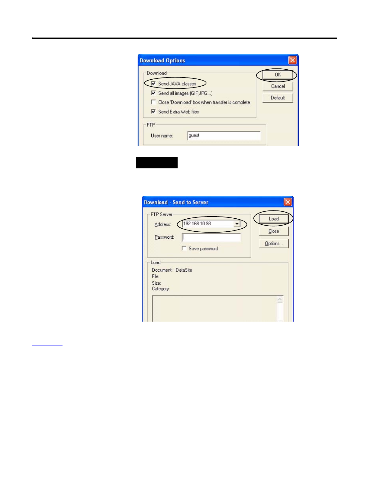
16. Check Send Java Classes
and click OK.
TIP
Checking the Send JAVA classes box is only required the first
time you download a project. Subsequent downloads do not
require you to check this box.
17. Load the web pages.
a. Select the IP address of
the DataSite unit.
b. Click the Load button.
Wait two to three
minutes to complete
the download process.
c. Click Close when you
see the message
Connection OK.
The DataSite web pages have been successfully downloaded to the DataSite unit. Refer to
Chapter 6
for system validation and an overview of the DataSite web pages.
52 Publication IASIMP-QS008A-EN-P - March 2009
Page 53

Chapter
5
FactoryTalk View Integration
Introduction
In this chapter, you download the FactoryTalk View ME project to a PanelView Plus 1000 terminal
connected to a ControlLogix 1756-L63 controller.
Before You Begin
• Complete your system hardware selection (Chapter 1).
• Complete your system layout and wiring (Chapter 2).
• Complete the DataSite and Logix Integration (Chapter 3).
• Complete the DataSite Workbench and Screen Builder integration (Chapter 4).
• Verify that all devices are connected properly and are powered up as shown in Connecting
All Devices on page 42.
What You Need
• Personal computer
• PanelView Plus 1000 terminal with Version 5.0 firmware
• Software:
– FactoryTalk View ME software
– DataSite Accelerator Toolkit CD
53Publication IASIMP-QS008A-EN-P - March 2009 53
Page 54
Chapter 5 FactoryTalk View Integration
Follow These Steps
Load and Restore FactoryTalk
View ME Application
page 54
Configure Local
Communication
page 56
Configure Target
Communication
page 59
Download Project to
PanelView Plus Terminal
page 61
Run the Project on PanelView
Plus Terminal
page 64
Load and Restore FactoryTalk View ME Application
Follow these steps to load and restore the FactoryTalk View Machine Edition (ME) application
from the DataSite Accelerator Toolkit CD using the Application Manager.
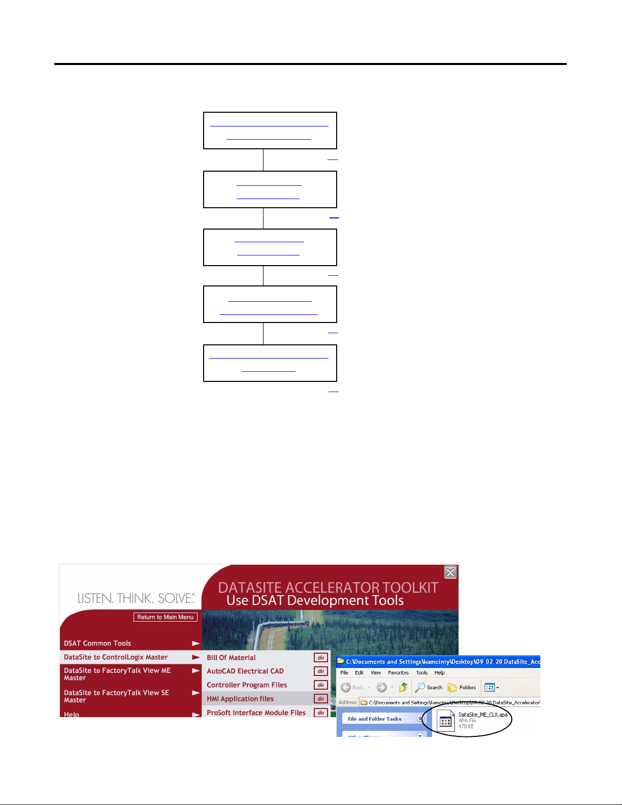
1. On the toolkit CD, choose DataSite to ControlLogix Master>HMI Application Files, then
double-click the DataSite_ME_CLX.apa application file.
54 Publication IASIMP-QS008A-EN-P - March 2009
Page 55
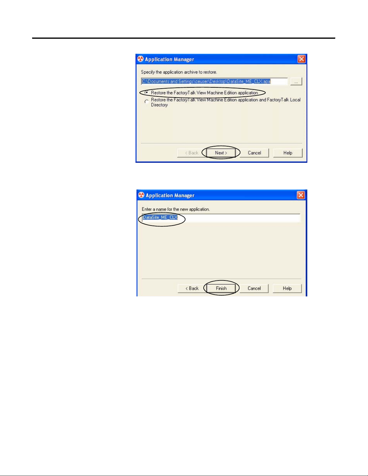
The Application Manager
window opens.
2. Select Restore the
FactoryTalk View
Machine Edition
application and click
Next.
3. Type DataSite_ME_CLX as
the application name and
click Finish.
FactoryTalk View Integration Chapter 5
The Application Manager
closes after it restores the
application.
Publication IASIMP-QS008A-EN-P - March 2009 55
Page 56
Chapter 5 FactoryTalk View Integration
Configure Local Communication
The Design (Local) tab in Communications Setup reflects the view of the topology from the
RSLinx Enterprise server on the development computer. In this example, the development
computer is communicating to a ControlLogix L63 controller via Ethernet communication.
Follow these steps to configure local communication.
1. Apply power to your ControlLogix L63 controller.
2. Verify all cable connections as shown in the wiring diagram on page 42.
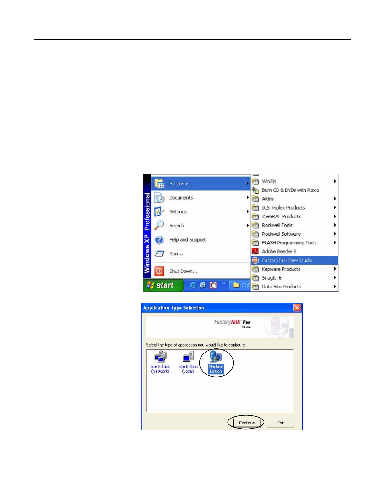
3. Launch FactoryTalk View
Studio software.
If you see this dialog box,
select Machine Edition
and click Continue.
56 Publication IASIMP-QS008A-EN-P - March 2009
Page 57

4. Select DataSite_ME_CLX
from the Existing tab and
click Open.
The Machine Edition
application opens.
5. Expand RSLinx Enterprise
in the Explorer window.
FactoryTalk View Integration Chapter 5
6. Double-click
Communication Setup.
Publication IASIMP-QS008A-EN-P - March 2009 57
Page 58
Chapter 5 FactoryTalk View Integration
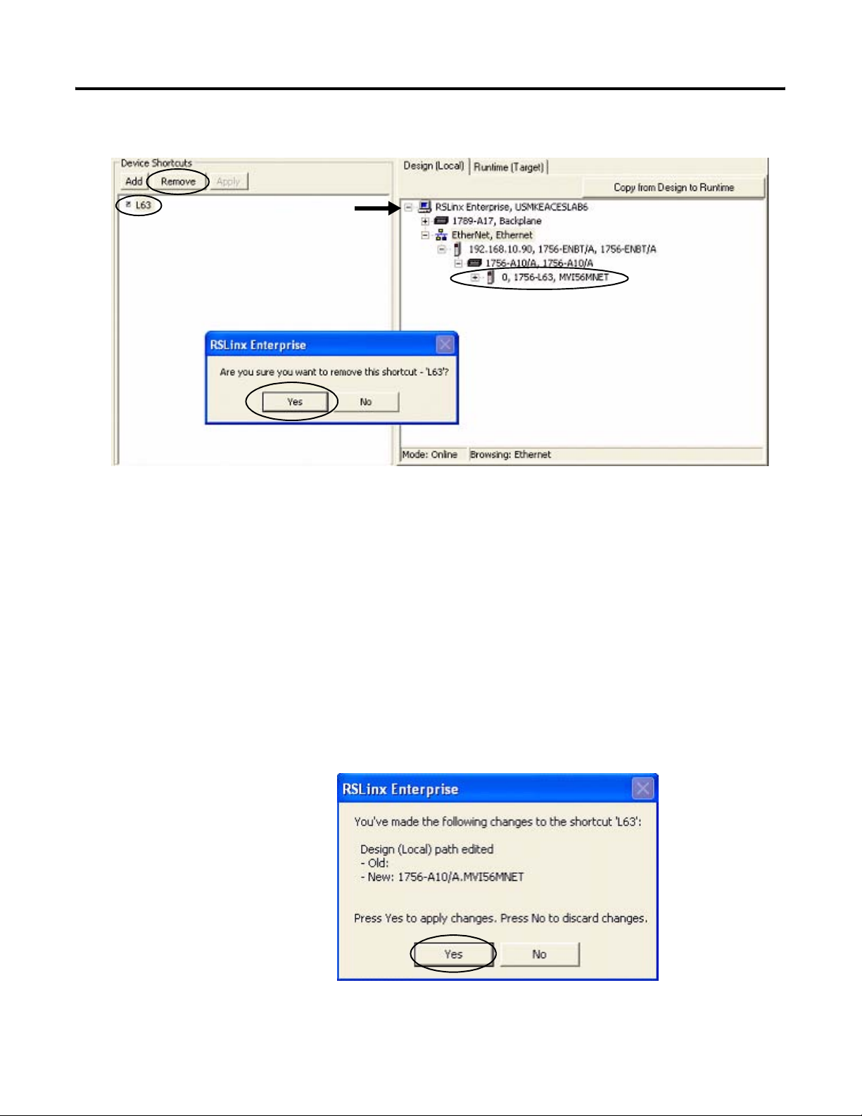
The Communication Setup window opens.
7. Select L63 under Device Shortcuts.
8. Click Remove then click Yes to verify the removal of the shortcut.
9. Expand the RSLinx Enterprise tree to access your 1756-L63 controller in slot 0 (0, 1756-L63).
10. Click Add under Device Shortcuts.
11. Enter L63 as the shortcut name and press Enter.
12. Select your Logix controller 0, 1756-L63.
13. Click Apply under Device Shortcuts.
14. Click Yes to apply changes.
58 Publication IASIMP-QS008A-EN-P - March 2009
Page 59
FactoryTalk View Integration Chapter 5
Configure Target Communication
The Runtime (Target) tab displays the offline configuration from the perspective of the device that
is running the application and comprises the topology that is loaded in the PanelView Plus
terminal. In this example, the PanelView Plus terminal communicates to the same
ControlLogix L63 controller via Ethernet communication.
Follow these steps to configure target communication.
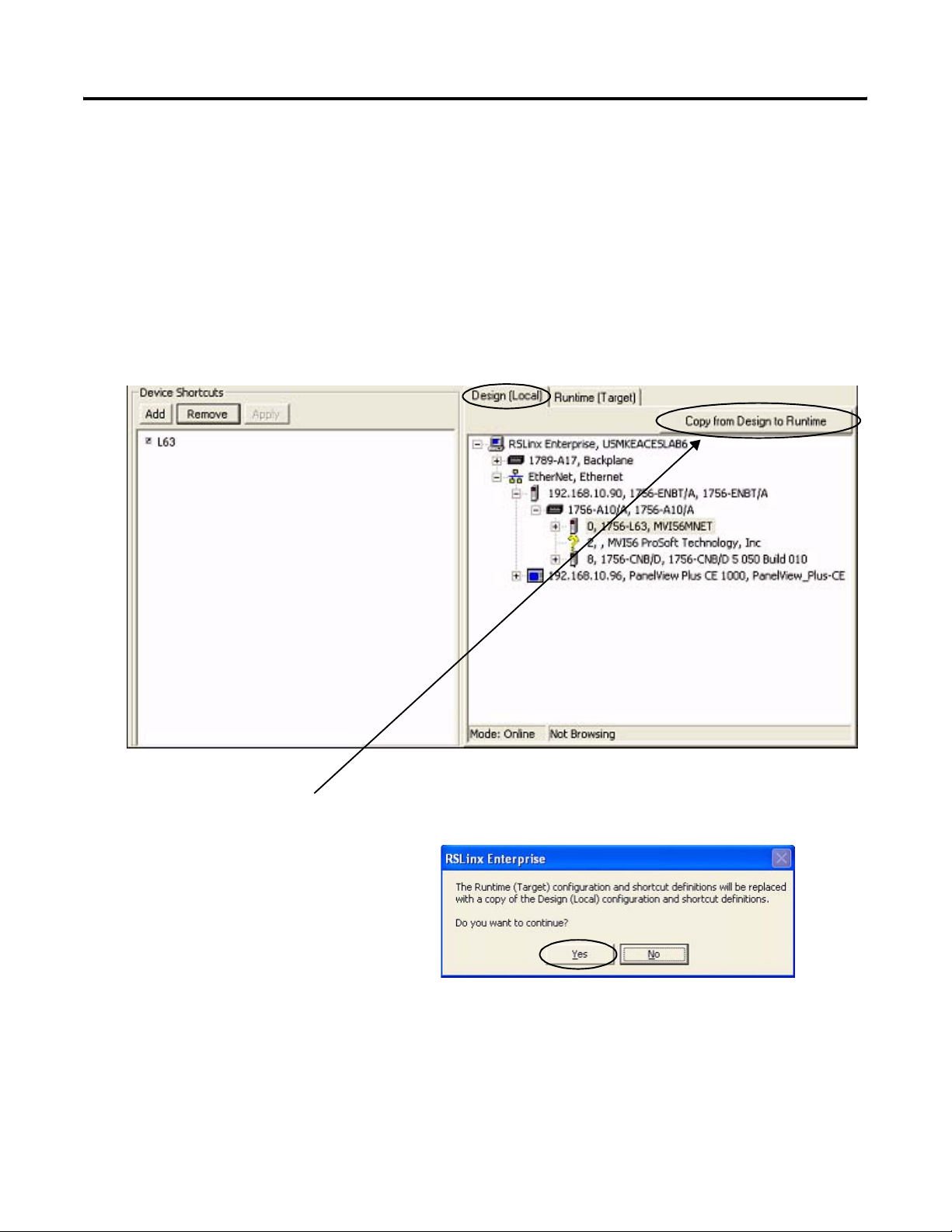
1. Select the Design (Local) tab in the Communication Setup window.
2. Click Copy from Design to Runtime.
A dialog box prompts you to confirm
the operation.
3. Click Yes.
Publication IASIMP-QS008A-EN-P - March 2009 59
Page 60

Chapter 5 FactoryTalk View Integration
4. Select the Runtime (Target) tab and expand the RSLinx Enterprise tree.
5. Click the L63 shortcut to verify that your controller and shortcut name are both highlighted.
In this example, 1756-L63 is the controller in slot 0 and L63 is the shortcut name.
6. Click OK at the bottom right corner of the
window.
60 Publication IASIMP-QS008A-EN-P - March 2009
Page 61

FactoryTalk View Integration Chapter 5
Download Project to PanelView Plus Terminal
Follow these steps to create a FactoryTalk View ME runtime file and download it to the
PanelView Plus terminal.
1. Choose Create Runtime
Application from the
Application menu.
The Create Runtime
Application dialog box
opens.
2. Select Runtime 5.0
Application (*.mer) from
the Save as type list.
3. Type
DataSite_ME_CLX.mer in
the File name field.
4. Click Save and wait for
the progress bar to
complete.
5. Click the File Transfer
Utility button on the
toolbar.
Publication IASIMP-QS008A-EN-P - March 2009 61
Page 62
Chapter 5 FactoryTalk View Integration
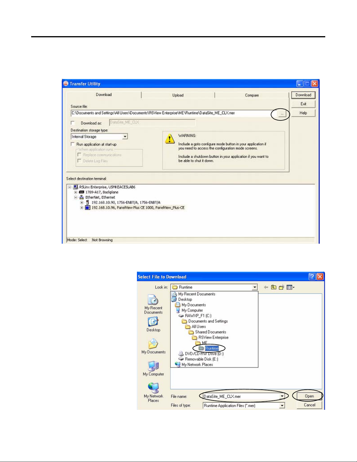
The Transfer Utility opens.
6. Click the Browse ... button to locate the runtime file.
7. Select DataSite_ME_CLX.mer
from the Runtime folder.
8. Click Open.
Default Runtime folder path:
C:\Documents and Settings\All Users\Documents\RSView Enterprise\ME\Runtime
62 Publication IASIMP-QS008A-EN-P - March 2009
Page 63

FactoryTalk View Integration Chapter 5
9. Browse and select your PanelView Plus terminal, then click Download.
TIP
10. Click OK when the
download completes
successfully.
11. Click Exit to close the File
Transfer Utility.
12. Choose Exit from the File
menu to close the
FactoryTalk View Studio
software.
If the PanelView Plus terminal has an existing .mer file with the same name, click Yes to
overwrite the file.
Publication IASIMP-QS008A-EN-P - March 2009 63
Page 64
Chapter 5 FactoryTalk View Integration
Run the Project on PanelView Plus Terminal
The (.mer) runtime file is now stored in the PanelView Plus terminal so you are ready to run the
project on the terminal.
Follow these steps to run your project on the PanelView Plus terminal.
1. Verify that the PanelView
Plus is connected as
shown on page 42 and
that it is receiving power.
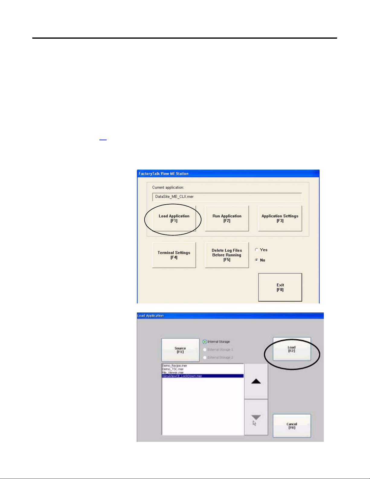
2. Press Load Application
[F1] in the FactoryTalk
View ME Station dialog
box.
The Load Application
dialog box opens.
3. Use the up/down arrows
to scroll through the list
of applications and select
DataSite_ME_CLX.mer.
4. Press Load [F2].
64 Publication IASIMP-QS008A-EN-P - March 2009
Page 65

5. Press Yes [F7].
If you press No, the
communication settings
from the previously run
project will be used.
6. Wait for the application to
the load and verify that
DataSite_ME_CLX.mer
appears under Current
application.
FactoryTalk View Integration Chapter 5
7. Press Run Application
[F2].
The application builds and displays a DataSite screen on the PanelView Plus terminal.
Refer to Chapter 6 for system validation.
Publication IASIMP-QS008A-EN-P - March 2009 65
Page 66

Chapter 5 FactoryTalk View Integration
66 Publication IASIMP-QS008A-EN-P - March 2009
Page 67

Chapter
6
System Validation
Introduction
In this chapter, you validate the DataSite system by verifying that all AGA flow data can be seen
on the PanelView Plus 1000 terminal and on the DataSite web pages.
Before You Begin
• Complete your system hardware selection (Chapter 1).
• Complete your system layout and wiring (Chapter 2).
• Complete the DataSite and Logix Integration (Chapter 3).
• Complete the DataSite Workbench and Screen Builder integration (Chapter 4).
• Complete the FactoryTalk View integration (Chapter 5).
• Verify that all devices are connected properly and are powered up as shown in Connecting
All Devices on page 42.
What You Need
• Personal computer
• All product hardware from the previous chapters
• Software:
– DS Flo Config
– DataSite Workbench
– RSLogix 5000
– Java Runtime Environment, Version 6 Update 7
– DataSite Accelerator Toolkit CD, publication IASIMP-SP011
67Publication IASIMP-QS008A-EN-P - March 2009 67
Page 68
Chapter 6 System Validation
Follow These Steps
Validate DataSite to PanelView
Plus Communication
Validate DataSite Web
Review DataSite Workbench
page 69
Pages
page 75
User Program
page 80
68 Publication IASIMP-QS008A-EN-P - March 2009
Page 69
System Validation Chapter 6
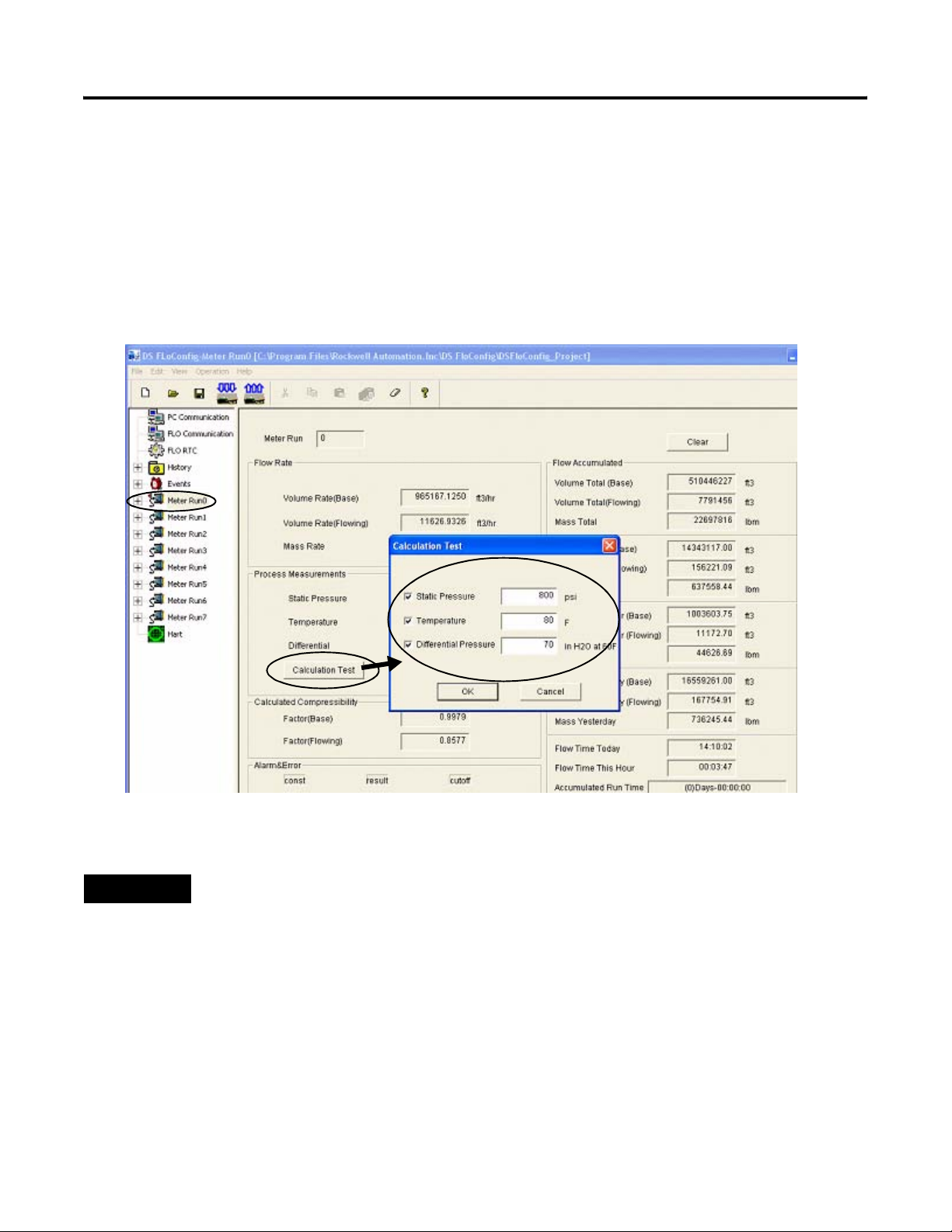
Validate DataSite to PanelView Plus Communication
You are now ready to validate communication between the DataSite unit and the PanelView Plus
terminal. Using the DS FloConfig software, you will simulate three process variables and validate
that the calculated flow values display on the PanelView Plus terminal.
TIP
To use actual process variables, wire temperature, pressure, and differential pressure transmitters to the
DataSite analog inputs.
Follow these steps to perform the system validation.
1. Launch the DS
FloConfig software.
The path shown may
be different on your
computer depending
on where the
software is installed.
2. Select Open Recent
Project and click OK.
This DS FloConfig file was created in Chapter 1.
Publication IASIMP-QS008A-EN-P - March 2009 69
Page 70
Chapter 6 System Validation
3. Select MeterRun0 on the left side of the dialog box.
4. Click Calculation Test and check all three boxes.
a. Type 800 for Static
Pressure.
b. Type 80 for Temperature.
c. Type 70 for Differential Pressure.
d. Click OK.
TIP
70 Publication IASIMP-QS008A-EN-P - March 2009
You can optionally repeat steps 3 and 4 for Meter Run1 through Meter Run7.
Page 71
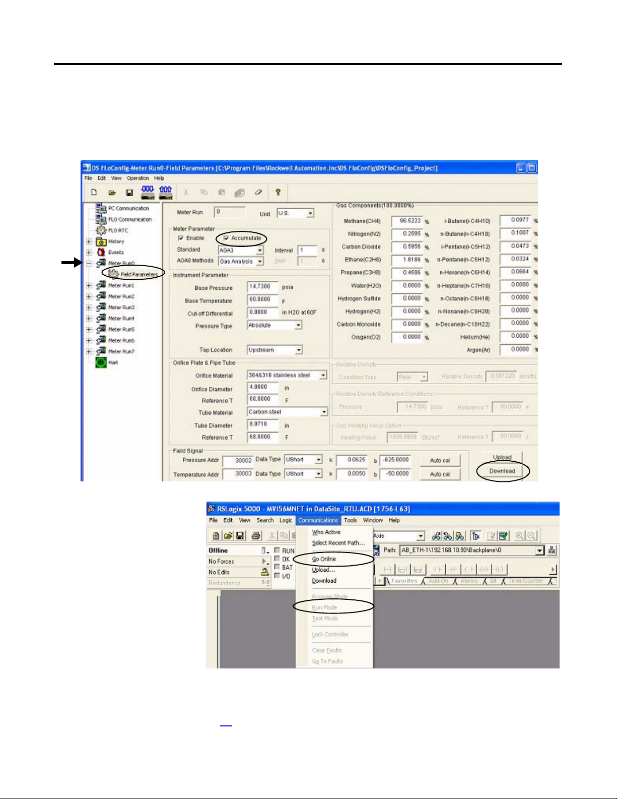
5. Click OK when you see the message Download Successful.
6. Expand Meter Run0, select Field Parameters, then click Upload.
7. Check Accumulate and click Download.
System Validation Chapter 6
8. Return to the RSLogix
5000 software.
9. Choose Online from
the Communication
menu and place your
L63 ControlLogix
controller in Run
mode.
10. Verify the FactoryTalk View ME project is running on the PanelView Plus 1000 terminal.
If necessary, refer to page 61 for instructions on how to download and run the project.
Publication IASIMP-QS008A-EN-P - March 2009 71
Page 72
Chapter 6 System Validation
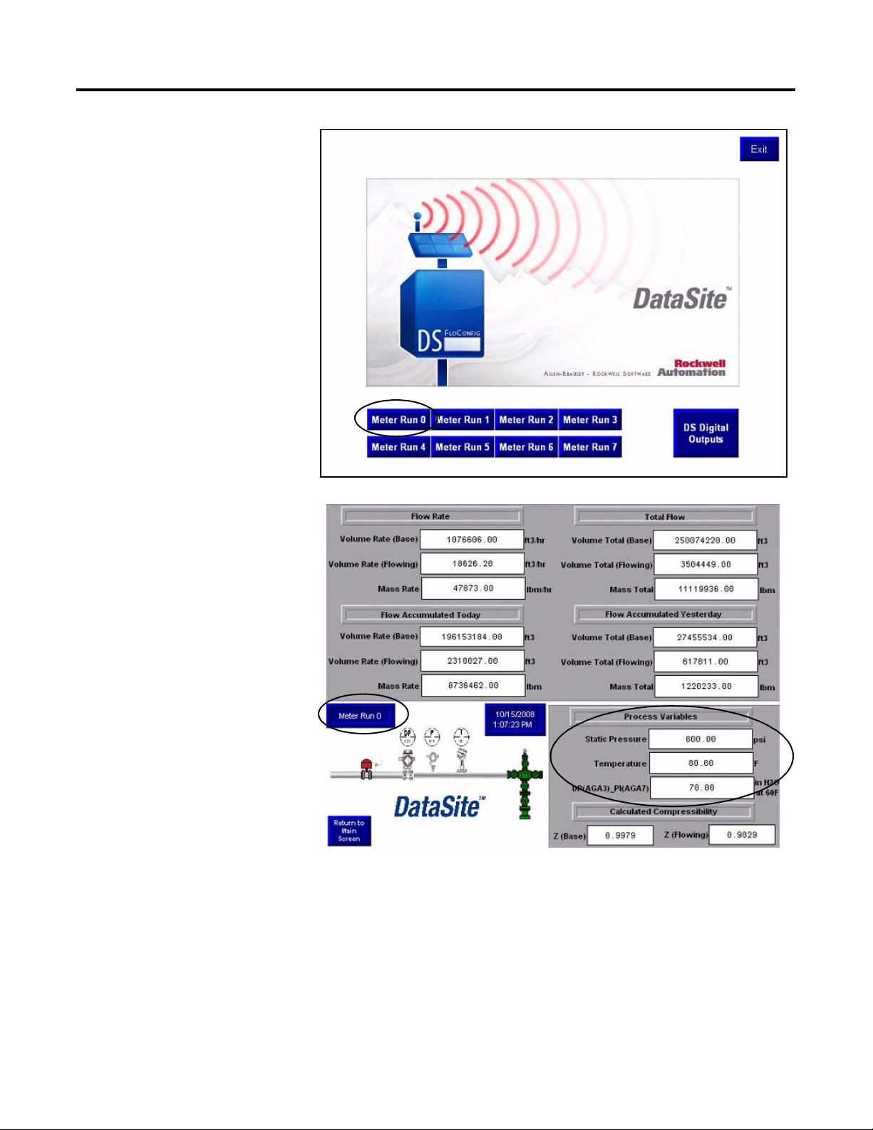
11. Press Meter Run 0 on the
PanelView Plus terminal.
12. Verify the Meter Run 0
process variables are the
same as DS FloConfig on
the next page.
72 Publication IASIMP-QS008A-EN-P - March 2009
Page 73

DS FloConfig Process Variables
System Validation Chapter 6
13. Press Return to Main
Screen on the PanelView
Plus terminal.
TIP
You can optionally repeat steps 9 through 12 to validate the process variables for Meter
Run 1 through Meter Run 7.
Publication IASIMP-QS008A-EN-P - March 2009 73
Page 74

Chapter 6 System Validation
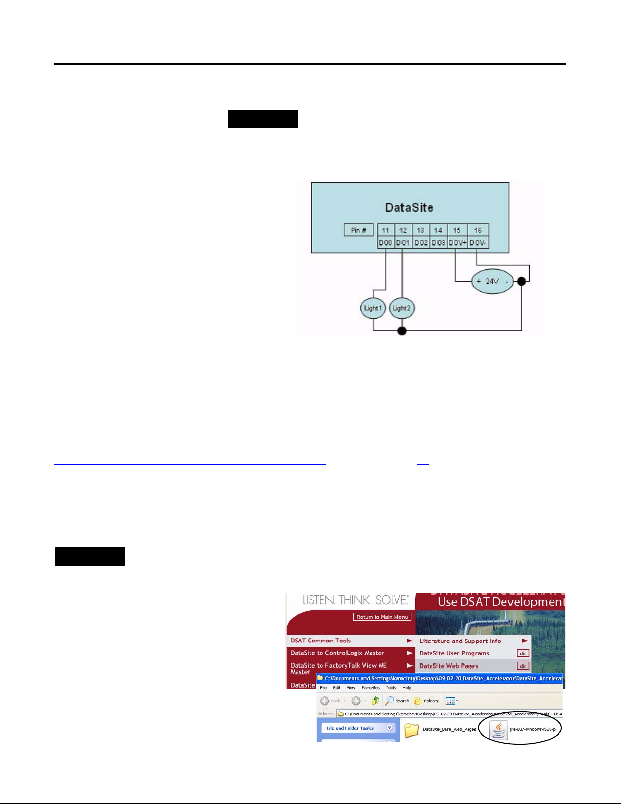
14. Press DS Digital Outputs
on the main PanelView
screen to validate control
of the DataSite digital
outputs.
15. Press a digital output.
The push button on the
left turns ON digital
output 0.
The push button on the
right turns ON digital
output 1.
74 Publication IASIMP-QS008A-EN-P - March 2009
Page 75
System Validation Chapter 6
TIP
To verify this functionality, you must wire a testing device such
as a stack light into digital output 0 and another device into
digital output 1. You must also supply the required voltage to
terminals DOV+ and DOV-.
The configuration and validation of the Data Site unit to ControlLogix Master is now complete.
Validate DataSite Web Pages
You will now validate the web pages of the DataSite unit using the simulated values from the
Validate DataSite to PanelView Plus Communication section on page 69. To view the web pages,
you must have the latest Java runtime environment loaded on your computer. The DataSite
Accelerator Toolkit CD contains a copy of the required Java runtime environment.
Follow these steps to perform validation of the web pages.
TIP
1. From the toolkit CD, choose DSAT
Common Tools>DataSite Web Pages,
then double-click the executable,
jre-6u7-windows-i586-p.exe, to load
the Java Runtime Environment,
Version 6 Update 7.
You can skip step 1 if Version 6 Update 7 of the Java Runtime Environment is installed on your computer.
Publication IASIMP-QS008A-EN-P - March 2009 75
Page 76

Chapter 6 System Validation
2. Launch Internet Explorer.
3. In the Address bar, type http://192.168.10.93/datasite.html
Java takes about one
minute to load this
screen.
Similar to the PanelView
Plus terminal, the web
pages will display the
same flow data as in
DS FloConfig.
IMPORTANT
You must enter the correct IP address of the DataSite unit. This
quick start uses 192.168.10.93
4. Click Meter Run 0.
76 Publication IASIMP-QS008A-EN-P - March 2009
Page 77

5. Verify the process variables are the same as in DS FloConfig.
System Validation Chapter 6
6. Click Main Menu to return to the main application screen.
Publication IASIMP-QS008A-EN-P - March 2009 77
Page 78

Chapter 6 System Validation
7. Click Digital Outputs.
8. Click Digital Output 2.
78 Publication IASIMP-QS008A-EN-P - March 2009
Page 79

System Validation Chapter 6
9. Repeat the previous step
to verify Digital Output 3.
TIP
To verify this functionality, you must wire a testing device such
as a stack light into digital output 2 and another device into
digital output 3. You must also supply the required voltage
terminals DOV+ and DOV-.
You just completed web page validation. Modify the existing sample programs to meet your
application needs. This example only displays data for one meter run. Duplicate the example, to
add additional meter runs.
Publication IASIMP-QS008A-EN-P - March 2009 79
Page 80
Chapter 6 System Validation
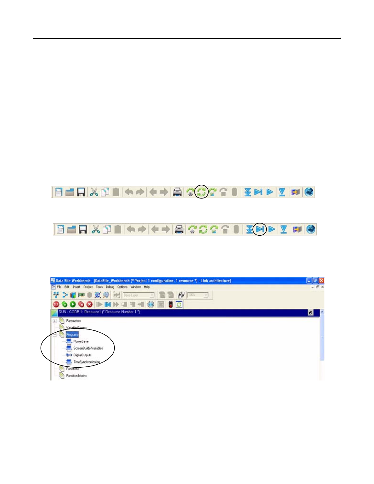
Review DataSite Workbench User Program
The sample DataSite Workbench project consists of four programs.
• Power Save - Saves power by turning power on/off to the LEDs, serial port, and RS485 port.
• Screen Builder Variables - Reads Meter Run 0 flow data variables and assigns a DataSite
Workbench variable that can be used by the DataSite web pages.
• Digital Outputs - Controls DataSite digital outputs 2 and 3.
• Time Synchronization - Synchronizes the DataSite clock to the ControlLogix L63 controller
clock.
Follow these steps to view the DataSite Workbench program in Run mode.
1. Compile the DataSite Workbench user program by clicking Rebuild Project/Library.
2. Click Debug Target.
This lets you view a running program and make changes to the variables.
3. In Debug mode, double-click the program you want to view.
4. Refer to the program comments for details on functionality.
To view other programs, close the program editor window and double-click a different program
from the link architecture view.
80 Publication IASIMP-QS008A-EN-P - March 2009
Page 81
Appendix
A
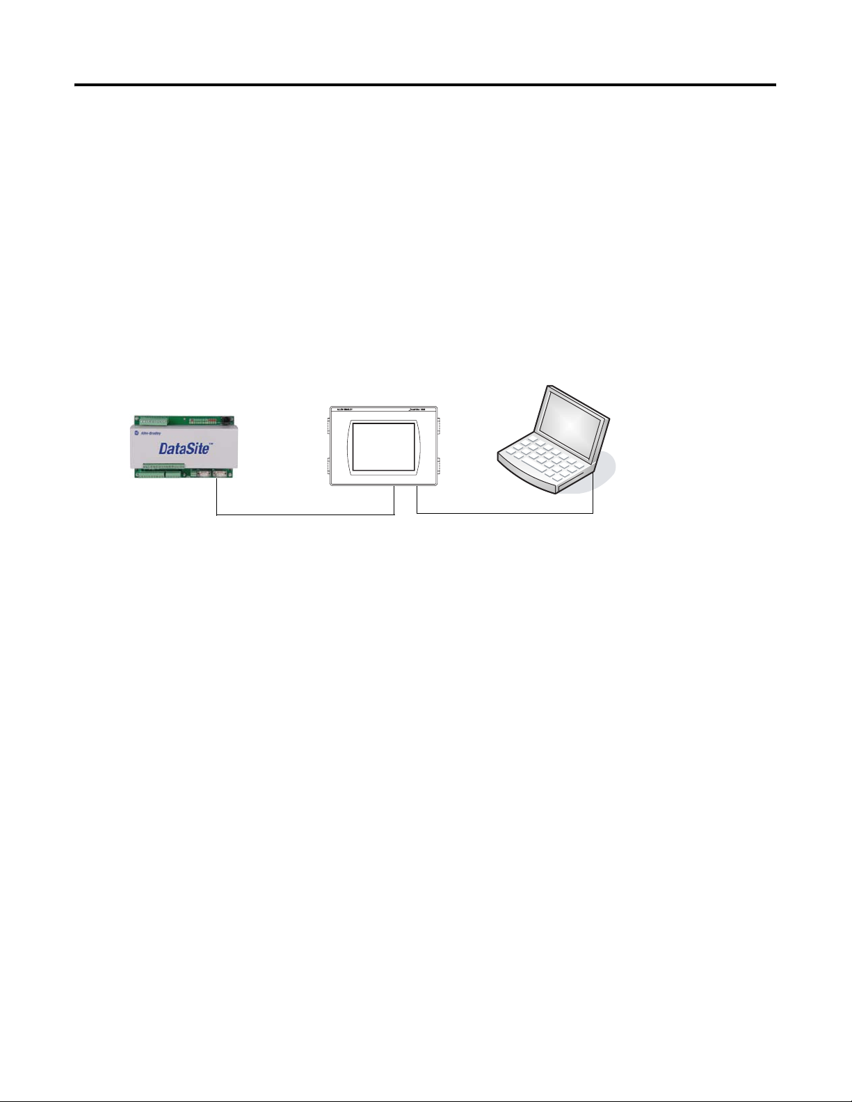
DataSite to FactoryTalk View ME Master
This appendix describes how to configure a PanelView Plus 600 terminal to communicate with
the DataSite using Modbus serial communication. This setup requires KEPServerEnterprise V4.0 to
configure drivers between the DataSite unit and the PanelView Plus terminal running FactoryTalk
View ME.
2711P PanelView Plus 600 Terminal
with Built-in Ethernet Port
Programming Computer
Running
FactoryTalk View ME
2711P-CBL-EX04
2711-NC13 Serial Cable
Use this setup for smaller applications that don't require a ControlLogix controller to poll multiple
DataSite units. Refer to Appendix B for instructions on how to configure a Factory Talk View SE
master to communicate with the DataSite via Modbus TCP/IP communication that don’t require a
controller but do require data logging parameters to an excel file.
Ethernet Crossover Cable
Before You Begin
• Download KEPServer Enterprise V4.0.
• Wire the DataSite unit to the PanelView Plus 600 terminal using the 2711-NC13 serial cable.
• Apply Power to the DataSite unit and PanelView Plus 600 terminal.
What You Need
• Personal computer
• Hardware:
– DataSite unit
– PanelView Plus 600 terminal
81Publication IASIMP-QS008A-EN-P - March 2009 81
Page 82

Appendix A DataSite to FactoryTalk View ME Master
– 2711C-NC13 serial cable
– 2711P-CBL-EX04 Ethernet crossover cable
• Software:
– KEPServerEnterprise V4.0
– FactoryTalk View Studio ME
– DataSite Accelerator Toolkit CD, publication IASIMP-SP011
Follow These Steps
Load KEPServerEnterprise
File
page 83
Load FactoryTalk View ME
Application
page 85
Validate Communication
Between DataSite and Terminal
page 88
82 Publication IASIMP-QS008A-EN-P - March 2009
Page 83
DataSite to FactoryTalk View ME Master Appendix A
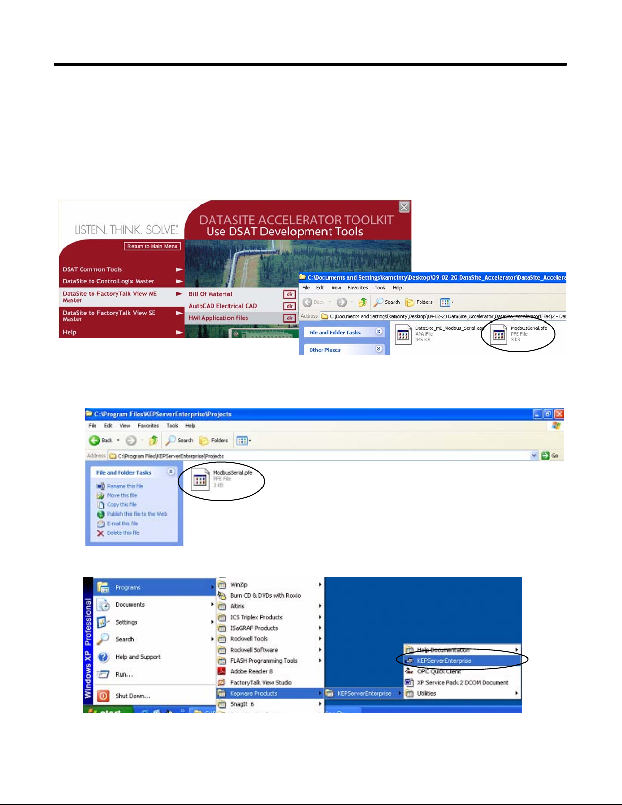
Load KEPServerEnterprise File
Follow these steps to load a KEPServer Enterprise .pfe file that contains Modbus addresses of the
parameters to be polled and displayed on the PanelView Plus 600 HMI terminal.
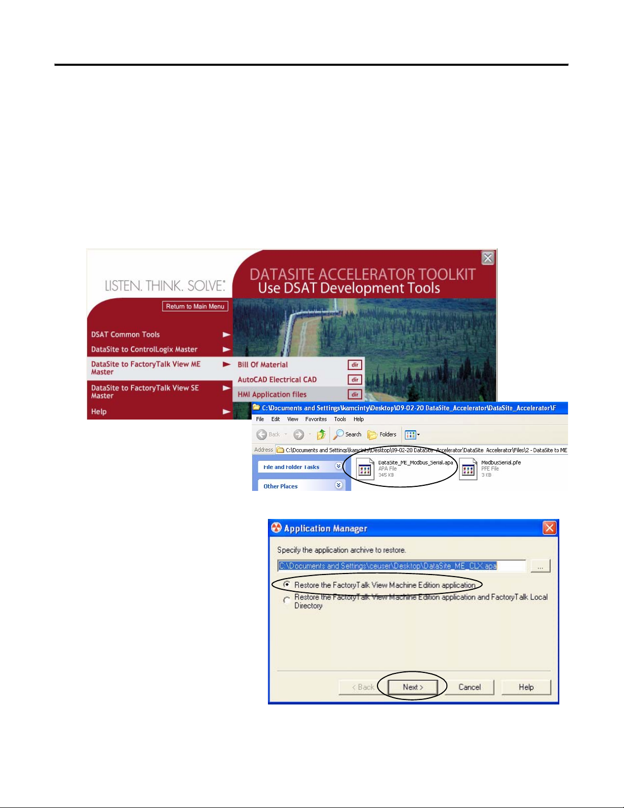
1. From the DataSite Accelerator Toolkit CD, choose DataSite to FactoryTalk View ME
Master>HMI Application files.
2. Copy ModbusSerial.pfe from the CD to the default project folder for KEPServerEnterprise.
C:\Program Files\KEPServerEnterprise\Projects
3. Launch KEPServerEnterprise V4.0.
4. Choose Open from the File menu, then locate and open the ModbusSerial.pfe file.
Publication IASIMP-QS008A-EN-P - March 2009 83
Page 84
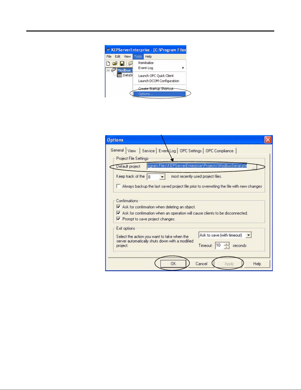
Appendix A DataSite to FactoryTalk View ME Master
5. From the Tools menu,
Choose Options.
6. Click the Browse ...
button to locate the
default project
ModbusSerial.pfe.
7. Click Apply.
8. Click OK.
C:\Program Files\KEPServerEnterprise\Projects\ModbusSerial.pfe
84 Publication IASIMP-QS008A-EN-P - March 2009
Page 85
DataSite to FactoryTalk View ME Master Appendix A
Load FactoryTalk View ME Application
The FactoryTalk View ME application contains screens to display flow data on a PanelView Plus
600 terminal for one meter run.
Follow these steps to load the FactoryTalk View ME application from the DataSite Accelerator
Toolkit CD.
1. On the toolkit CD, choose DataSite to FactoryTalk View ME Master>HMI Application Files,
then double-click DataSite_ME_Modbus_Serial.apa.
The Application Manager
window opens.
2. Select Restore the FactoryTalk
View Machine Edition
application and click Next.
Publication IASIMP-QS008A-EN-P - March 2009 85
Page 86
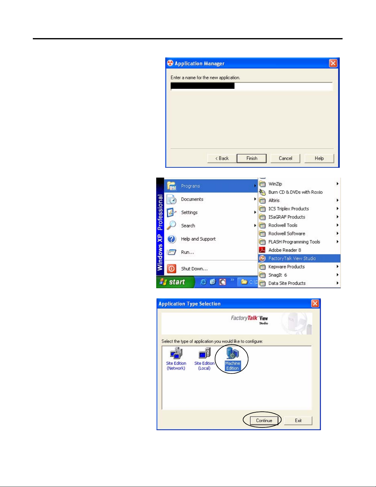
Appendix A DataSite to FactoryTalk View ME Master
3. Type DataSite_ME_Modbus_Serial
as the application name, then click
Finish.
The Application Manager closes
after it restores the application.
4. Launch FactoryTalk View
Studio software.
DataSite_ME_Modbus_Serial
5. If this dialog box opens, select
Machine Edition and click
Continue.
86 Publication IASIMP-QS008A-EN-P - March 2009
Page 87

DataSite to FactoryTalk View ME Master Appendix A
6. Select DataSite_ME_Modbus_Serial
from the Existing tab and click
Open.
The FactoryTalk View ME
application opens.
7. Create the .mer file and download to the PanelView Plus 600 terminal.
TIP
Refer to Download Project to PanelView Plus Terminal
create a runtime application and download the .mer application file to the PanelView
Plus 600 terminal.
on page 61 for details on how to
Publication IASIMP-QS008A-EN-P - March 2009 87
Page 88

Appendix A DataSite to FactoryTalk View ME Master
Validate Communication Between DataSite and Terminal
You are now ready to run the .mer application on the PanelView Plus 600 terminal, and validate
communication with the DataSite unit. The KEPServer (.pfe) file polls 19 parameters for one
meter run and displays the data on the PanelView Plus 600 terminal.
TIP
The validation assumes that AGA calculations were initiated using instrumentation
devices or simulated in DS FloConfig. Refer to Chapter 6
simulate the AGA process variables.
for more information on how to
Follow these steps to validate Modbus Serial communication between the DataSite unit and
PanelView Plus 600 terminal.
1. Make sure the COM1 or COM2 port of the DataSite is connected to the serial port of the
PanelView Plus terminal by using a 2711-NC13 straight-through cable.
2711-NC13 Straight-through Cable
TIP
If using radios, connect one serial radio to the DataSite and the
other radio to the PanelView Plus 600 terminal.
2. From the PanelView Plus
terminal, press Load
Application [F1] in the
FactoryTalk View ME
Station dialog box.
88 Publication IASIMP-QS008A-EN-P - March 2009
Page 89
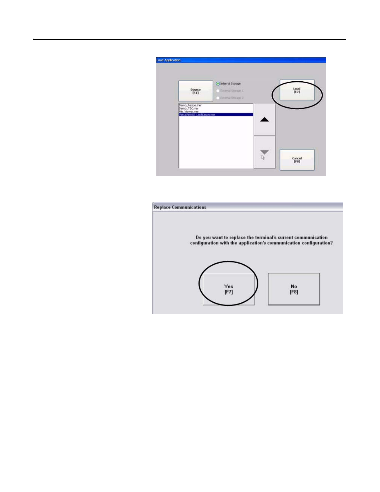
The Load Application dialog
box opens.
3. Use the up/down arrows to
scroll through the list of
applications and select
DataSite_ME_Modbus_Serial.
4. Press Load [F2].
5. Press Yes [F7].
DataSite to FactoryTalk View ME Master Appendix A
If you press No, the
communication settings from
the previously run project will
be used.
Publication IASIMP-QS008A-EN-P - March 2009 89
Page 90
Appendix A DataSite to FactoryTalk View ME Master
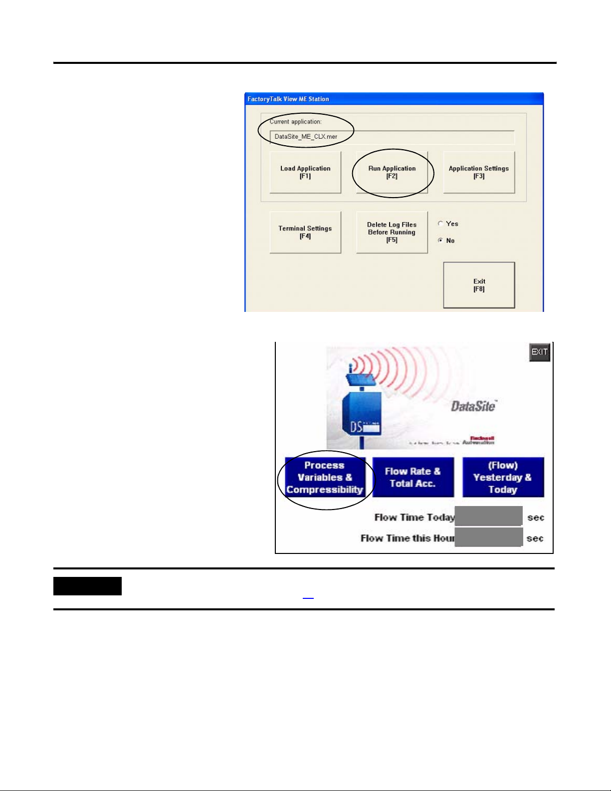
6. Wait for the application to the
load and verify that
DataSite_ME_Modbus_Serial.
mer appears under Current
application.
7. Press Run Application [F2].
The application builds and displays
a DataSite screen on the PanelView
Plus terminal.
8. Press Process Variables &
Compressibility.
Verify the process variables match
the numbers simulated using DS
FloConfig:
– Static Pressure = 800
– Temperature = 80
– Differential Pressure = 70
IMPORTANT
If the PanelView Plus terminal displays asterisks instead of data, then you need to select a different COM
port for the Serial DF1 driver. Skip to page
91 for instructions on how to change the COM port.
2800
800
9. Return to the main screen and press the other two blue buttons to view accumulated flow
data.
The flow data displayed is for Meter Run 0 (MR0). You can easily add other meter runs by adding
the corresponding Modbus registers in the KEPServerEnterprise (.pfe) file. You must then
duplicate the ME screens and change the tag names to match their corresponding tag name.
Configuration and validation of the DataSite to ME Master configuration is now complete.
90 Publication IASIMP-QS008A-EN-P - March 2009
Page 91
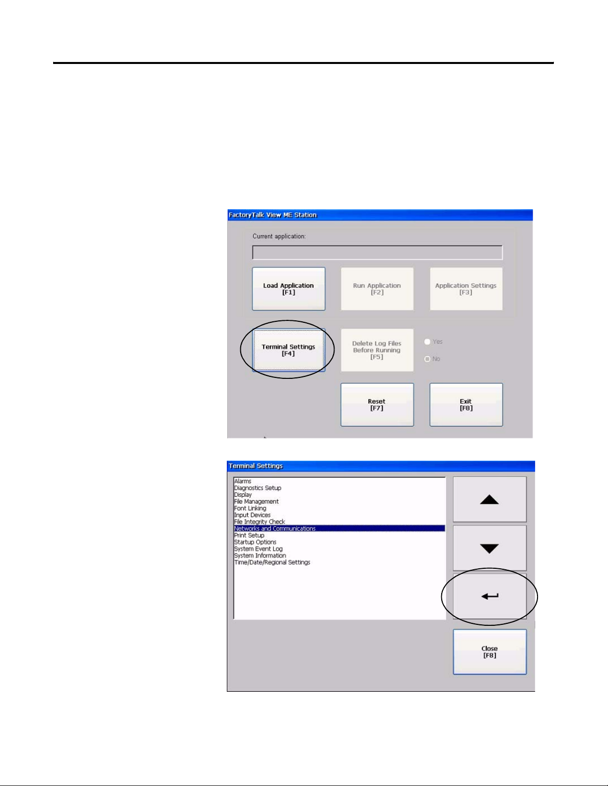
DataSite to FactoryTalk View ME Master Appendix A
Select a Different COM Port for the Serial DF1 Driver
If the variable data appears as asterisks on the PanelView Plus terminal, you need to change the
COM port used by the serial DF1 driver. If data appears correctly on the terminal, you can skip
this section.
Follow these steps to select a different COM port for the serial DF1 driver.
1. Press Terminal Settings
[F4] in the FactoryTalk
View ME Station dialog
box.
2. Select Networks and
Communications, then
press the Enter button.
Publication IASIMP-QS008A-EN-P - March 2009 91
Page 92

Appendix A DataSite to FactoryTalk View ME Master
3. Select RSLinx Enterprise
Communications by
pressing the cursor key,
then press the Enter
button.
4. Select Serial-DF1, then
press Edit Driver [F2].
92 Publication IASIMP-QS008A-EN-P - March 2009
Page 93
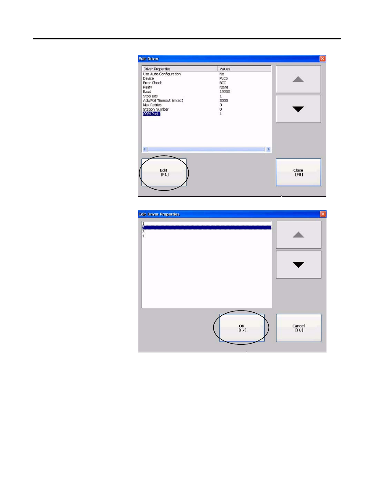
5. Select COM Port, then
press Edit [F1].
DataSite to FactoryTalk View ME Master Appendix A
6. Select 2, then press OK
[F7].
Publication IASIMP-QS008A-EN-P - March 2009 93
Page 94
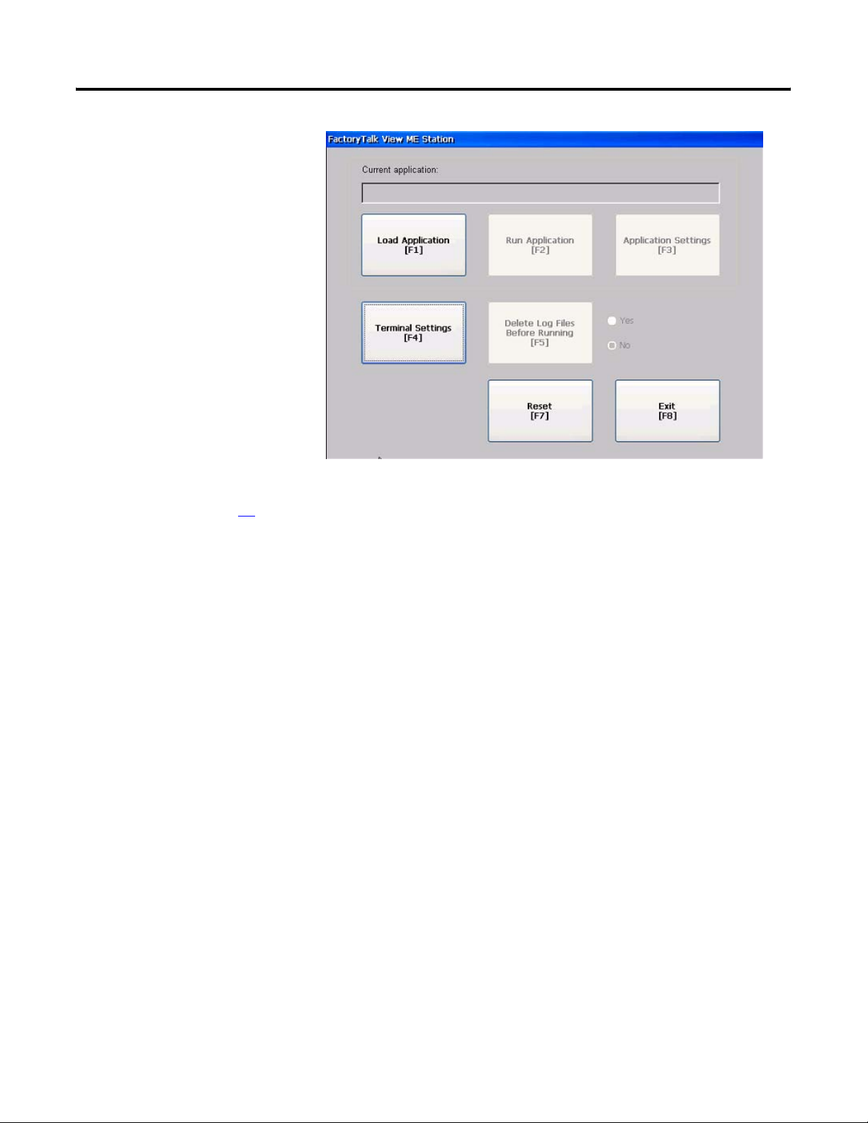
Appendix A DataSite to FactoryTalk View ME Master
7. Press the Cancel [F8]
button until you return to
the main menu.
8. Repeat steps 2 through 8
starting on page 88 to
validate the application.
94 Publication IASIMP-QS008A-EN-P - March 2009
Page 95

Appendix
B
DataSite to FactoryTalk View SE Master
This appendix shows how to configure an industrial computer running FactoryTalk View SE
software to communicate with a DataSite unit using Modbus TCP/IP communication. This setup
requires KEPServerEnterprise software V4.0 to configure the communication driver.
Remote Location
Radio
Ethernet
Crossover Cable
2711P-CBL-EX04
Host Location
Radio
Ethernet
Crossover Cable
2711P-CBL-EX04
6181P Industrial Computer Running
FactoryTalk View SE
This configuration is good for small applications that require data logging capabilities but don't
require a ControlLogix controller to poll multiple DataSite units. Refer to Appendix A for details
on how to configure a PanelView Plus terminal running Factory Talk View ME software to
communicate with the DataSite using Modbus serial communication.
TIP
Radios are optional. If your application does not require radios, simply replace the radios
with an Ethernet crossover cable connecting the DataSite to the industrial computer.
Before You Begin
• Download KEPServer Enterprise software V4.0.
• Connect the DataSite unit to an industrial computer running FactoryTalk View Site Edition
(SE) software.
• Radios are optional.
95Publication IASIMP-QS008A-EN-P - March 2009 95
Page 96
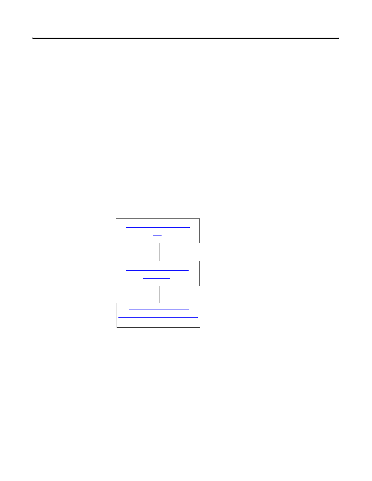
Appendix B DataSite to FactoryTalk View SE Master
What You Need
• Hardware:
– DataSite unit
– 6181P industrial computer or personal computer
– Two radios, optional
– Two 2711P-CBL-EX04 Ethernet crossover cables
• Software:
– KEPServerEnterprise V4.0
– FactoryTalk View SE
– DataSite Accelerator Toolkit CD, publication IASIMP-SP011
Follow These Steps
Load KEPServerEnterprise
File
page 97
Load FactoryTalk View SE
Application
page 99
Validate Communication
Between DataSite and Computer
page 106
96 Publication IASIMP-QS008A-EN-P - March 2009
Page 97
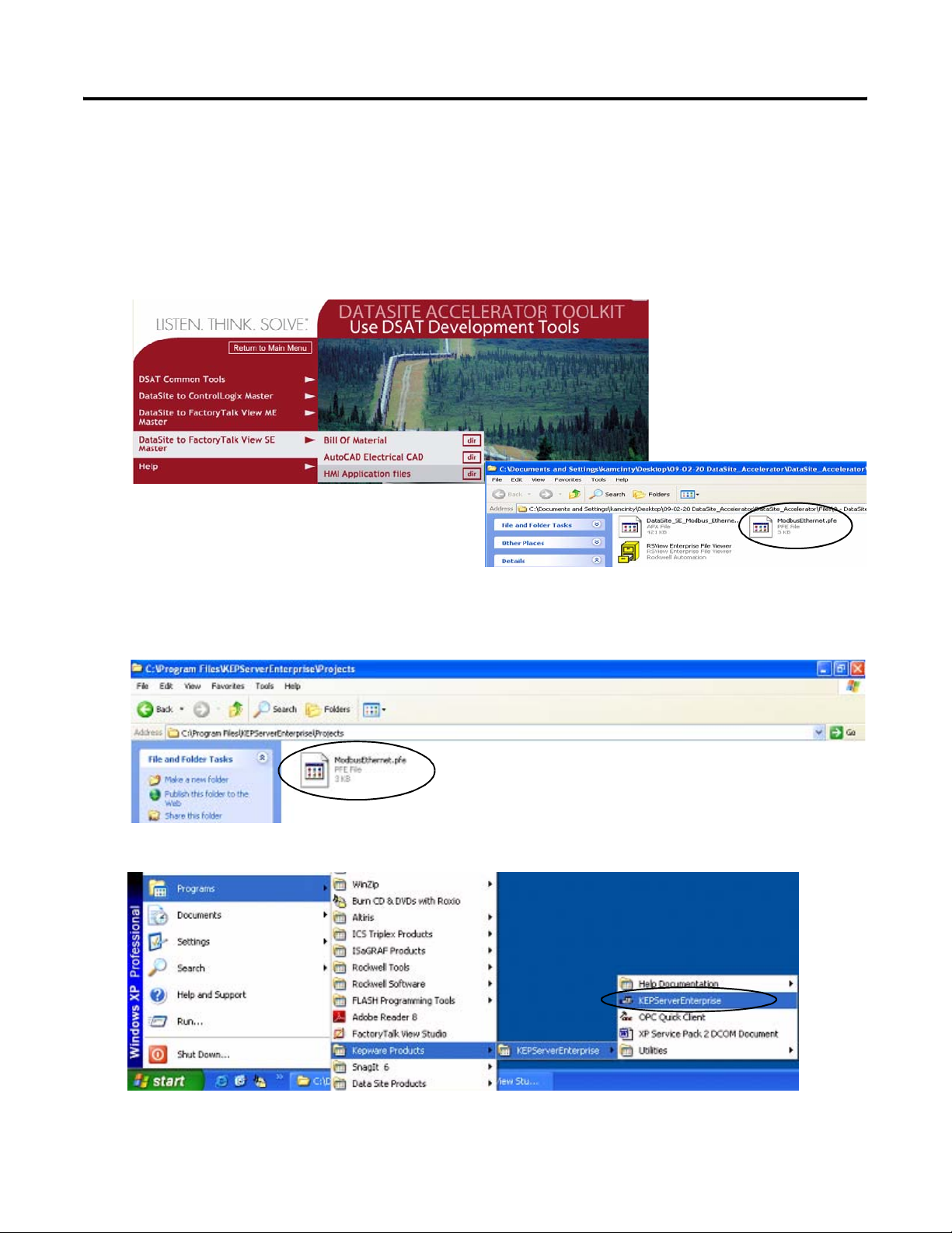
DataSite to FactoryTalk View SE Master Appendix B
Load KEPServerEnterprise File
Follow these steps to load a KEPServer Enterprise .pfe file that contains Modbus addresses of the
parameters to be polled and displayed on the industrial computer.
1. From the DataSite Accelerator Toolkit CD, choose DataSite to FactoryTalk View SE
Master>HMI Application Files.
2. Copy ModbusEthernet.pfe from the CD to the default project folder for KEPServerEnterprise.
C:\Program Files\KEPServerEnterprise\Projects
3. Launch KEPServerEnterprise software V4.0.
4. Choose Open from the File menu, then locate and open the ModbusEthernet.pfe file.
Publication IASIMP-QS008A-EN-P - March 2009 97
Page 98
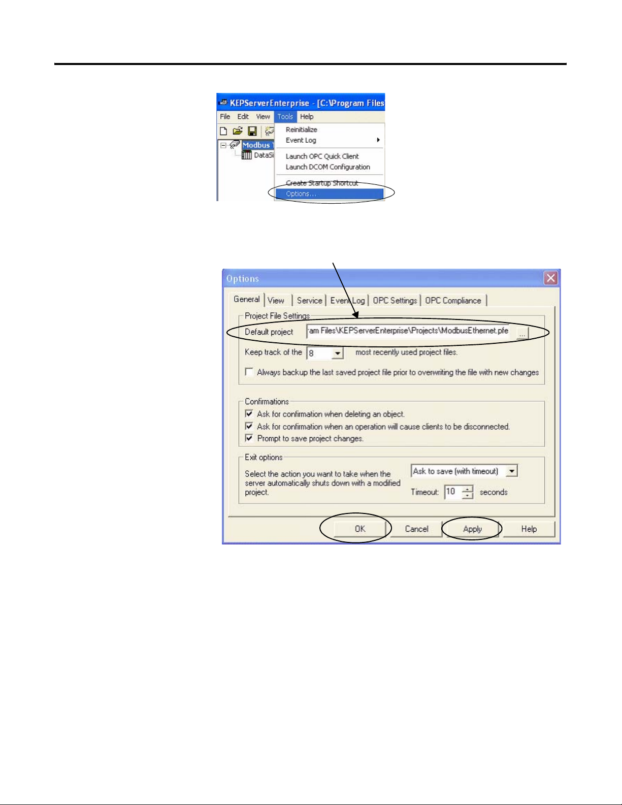
Appendix B DataSite to FactoryTalk View SE Master
5. Choose Options from
the Tools menu.
6. Click the Browse
button ... to locate the
default project
ModbusEthernet.pfe.
7. Click Apply.
8. Click OK.
C:\Program Files\KEPServerEnterprise\Projects\ModbusEthernet.pfe
98 Publication IASIMP-QS008A-EN-P - March 2009
Page 99
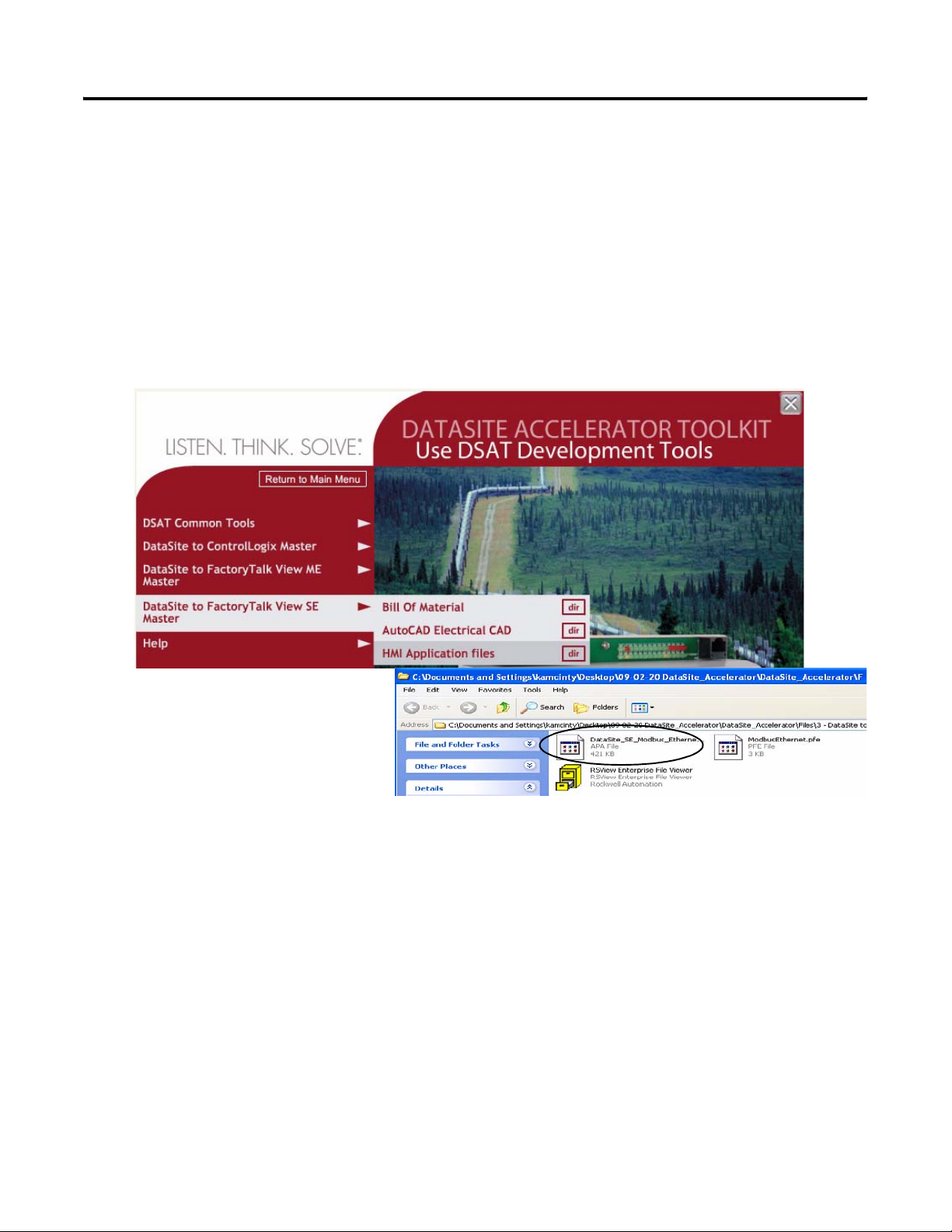
DataSite to FactoryTalk View SE Master Appendix B
Load FactoryTalk View SE Application
The FactoryTalk View SE application contains a screen that controls when to start and stop data
logging to an Excel file. It also contains a screen with gas flow data for Meter Run 0.
Follow these steps to load the FactoryTalk View SE application from the DataSite Accelerator
Toolkit CD.
1. On the toolkit CD, choose DataSite to FactoryTalk View SE Master>HMI Application files,
then double-click the DataSite_SE_Modbus_Ethernet.apa application file.
Publication IASIMP-QS008A-EN-P - March 2009 99
Page 100
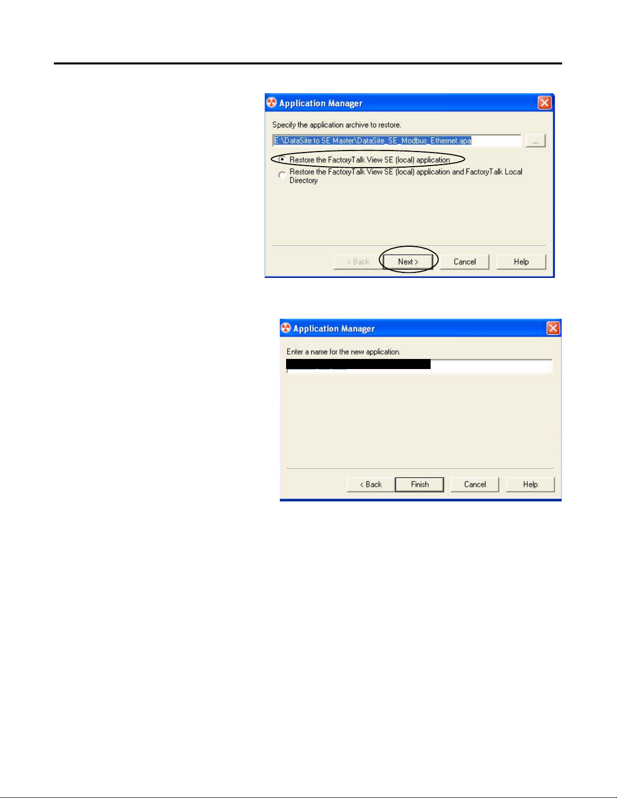
Appendix B DataSite to FactoryTalk View SE Master
The Application Manager
window opens.
2. Select Restore the FactoryTalk
View SE (local) application, then
click Next.
3. Enter DataSite_ME_Modbus_Ethernet
as the application name and click
Finish.
The Application Manager closes after
it restores the application.
DataSite_ME_Modbus_Ethernet
100 Publication IASIMP-QS008A-EN-P - March 2009
 Loading...