

Page 1

User Manual
FOUNDATION Fieldbus System
Catalog Numbers
1757-FFLDC2, 1757-FFLDC4
9308-RSFB64ENE, 9308-RSFB256ENE, 9308-RSFB1024ENE, 1757-FFLD2, 1757-FFLD4,
Page 2
Important User Information
IMPORTANT
Solid-state equipment has operational characteristics differing from those of electromechanical equipment. Safety
Guidelines for the Application, Installation and Maintenance of Solid State Controls (publication SGI-1.1
your local Rockwell Automation sales office or online at http://www.rockwellautomation.com/literature/
important differences between solid-state equipment and hard-wired electromechanical devices. Because of this difference,
and also because of the wide variety of uses for solid-state equipment, all persons responsible for applying this equipment
must satisfy themselves that each intended application of this equipment is acceptable.
In no event will Rockwell Automation, Inc. be responsible or liable for indirect or consequential damages resulting from
the use or application of this equipment.
The examples and diagrams in this manual are included solely for illustrative purposes. Because of the many variables and
requirements associated with any particular installation, Rockwell Automation, Inc. cannot assume responsibility or
liability for actual use based on the examples and diagrams.
No patent liability is assumed by Rockwell Automation, Inc. with respect to use of information, circuits, equipment, or
software described in this manual.
Reproduction of the contents of this manual, in whole or in part, without written permission of Rockwell Automation,
Inc., is prohibited.
Throughout this manual, when necessary, we use notes to make you aware of safety considerations.
WARNING: Identifies information about practices or circumstances that can cause an explosion in a hazardous
environment, which may lead to personal injury or death, property damage, or economic loss.
available from
) describes some
ATTENTION: Identifies information about practices or circumstances that can lead to personal injury or death,
property damage, or economic loss. Attentions help you identify a hazard, avoid a hazard, and recognize the
consequence
SHOCK HAZARD: Labels may be on or inside the equipment, for example, a drive or motor, to alert people that
dangerous voltage may be present.
BURN HAZARD: Labels may be on or inside the equipment, for example, a drive or motor, to alert people that
surfaces may reach dangerous temperatures.
Identifies information that is critical for successful application and understanding of the product.
Allen-Bradley, Rockwell Software, Rockwell Automation, RS Fieldbus, RSLogix 5000, ControlLog ix, RSNetWorx for ControlNet, Stratix 8000, RSNetWorx, CompactLogix, PlantPAx Process Automation System, Logix5000,
Integrated Architecture, and TechConnect are trademarks of Rockwell Automation, Inc.
Trademarks not belonging to Rockwell Automation are property of their respective companies.
Page 3

Table of Contents
Preface
FOUNDATION Fieldbus System
RSFieldbus Software Basics
Additional Resources . . . . . . . . . . . . . . . . . . . . . . . . . . . . . . . . . . . . . . . . . . . . . . . 9
Chapter 1
Introduction. . . . . . . . . . . . . . . . . . . . . . . . . . . . . . . . . . . . . . . . . . . . . . . . . . . . . 11
Fieldbus Standards . . . . . . . . . . . . . . . . . . . . . . . . . . . . . . . . . . . . . . . . . . . 11
EtherNet/IP and 1757-FFLD Linking Device Example . . . . . . . . . . . . . 12
ControlNet and 1757-FFLDC Linking Device Example . . . . . . . . . . . . 13
RSFieldbus Software Features . . . . . . . . . . . . . . . . . . . . . . . . . . . . . . . . . 14
Chapter 2
Introduction. . . . . . . . . . . . . . . . . . . . . . . . . . . . . . . . . . . . . . . . . . . . . . . . . . . . . 15
Main Window . . . . . . . . . . . . . . . . . . . . . . . . . . . . . . . . . . . . . . . . . . . . . . . . . . . 15
Licensed Blocks . . . . . . . . . . . . . . . . . . . . . . . . . . . . . . . . . . . . . . . . . . . . . . 16
Main Window Toolbar . . . . . . . . . . . . . . . . . . . . . . . . . . . . . . . . . . . . . . . 17
Project Window . . . . . . . . . . . . . . . . . . . . . . . . . . . . . . . . . . . . . . . . . . . . . . . . . 17
Project Window Toolbar. . . . . . . . . . . . . . . . . . . . . . . . . . . . . . . . . . . . . . 18
Fieldbus Window . . . . . . . . . . . . . . . . . . . . . . . . . . . . . . . . . . . . . . . . . . . . . . . . 18
Fieldbus Window Toolbar . . . . . . . . . . . . . . . . . . . . . . . . . . . . . . . . . . . . 19
Process Cell Window. . . . . . . . . . . . . . . . . . . . . . . . . . . . . . . . . . . . . . . . . . . . . 19
Process Cell Window Toolbar . . . . . . . . . . . . . . . . . . . . . . . . . . . . . . . . . 19
Strategy Window . . . . . . . . . . . . . . . . . . . . . . . . . . . . . . . . . . . . . . . . . . . . . . . . 20
Function Blocks and Parameters . . . . . . . . . . . . . . . . . . . . . . . . . . . . . . . 20
Strategy Toolbar . . . . . . . . . . . . . . . . . . . . . . . . . . . . . . . . . . . . . . . . . . . . . 21
Drawing Toolbar . . . . . . . . . . . . . . . . . . . . . . . . . . . . . . . . . . . . . . . . . . . . . 22
Alignment Toolbar . . . . . . . . . . . . . . . . . . . . . . . . . . . . . . . . . . . . . . . . . . . 23
Copy Attributes Toolbar . . . . . . . . . . . . . . . . . . . . . . . . . . . . . . . . . . . . . 24
Communication Window (error log) . . . . . . . . . . . . . . . . . . . . . . . . . . . . . . 25
Create an RSFieldbus
Software Project
Chapter 3
Introduction. . . . . . . . . . . . . . . . . . . . . . . . . . . . . . . . . . . . . . . . . . . . . . . . . . . . . 27
Initiate a Fieldbus Project . . . . . . . . . . . . . . . . . . . . . . . . . . . . . . . . . . . . . . . . . 28
Define the Server . . . . . . . . . . . . . . . . . . . . . . . . . . . . . . . . . . . . . . . . . . . . . 30
Create the Physical Component . . . . . . . . . . . . . . . . . . . . . . . . . . . . . . . . . . . 31
Create a New Bridge (linking device). . . . . . . . . . . . . . . . . . . . . . . . . . . 31
Create a New Fieldbus (H1) Link. . . . . . . . . . . . . . . . . . . . . . . . . . . . . . 33
Set the Macrocycle. . . . . . . . . . . . . . . . . . . . . . . . . . . . . . . . . . . . . . . . . . . . 34
Create a New Device. . . . . . . . . . . . . . . . . . . . . . . . . . . . . . . . . . . . . . . . . . 36
Create a New Function Block . . . . . . . . . . . . . . . . . . . . . . . . . . . . . . . . . 40
Create the Logical Component. . . . . . . . . . . . . . . . . . . . . . . . . . . . . . . . . . . . 43
Create a New Process Cell. . . . . . . . . . . . . . . . . . . . . . . . . . . . . . . . . . . . . 43
Create a New Control Module . . . . . . . . . . . . . . . . . . . . . . . . . . . . . . . . 45
Create a Function Block in Logical Component. . . . . . . . . . . . . . . . . 47
Create a New Strategy . . . . . . . . . . . . . . . . . . . . . . . . . . . . . . . . . . . . . . . . . . . . 48
Link Blocks . . . . . . . . . . . . . . . . . . . . . . . . . . . . . . . . . . . . . . . . . . . . . . . . . . 51
Rockwell Automation Publication 1757-UM012A-EN-P - July 2011 3
Page 4

Table of Contents
RSFieldbus Communication
Delete and Restore Links . . . . . . . . . . . . . . . . . . . . . . . . . . . . . . . . . . . . . . 53
Edit Line Links . . . . . . . . . . . . . . . . . . . . . . . . . . . . . . . . . . . . . . . . . . . . . . . 54
Use Tools for Function Block Characterization . . . . . . . . . . . . . . . . . . . . . 55
Offline Characterization . . . . . . . . . . . . . . . . . . . . . . . . . . . . . . . . . . . . . . 56
Online Characterization. . . . . . . . . . . . . . . . . . . . . . . . . . . . . . . . . . . . . . . 57
Customize Characterization Parameters . . . . . . . . . . . . . . . . . . . . . . . . 57
Design Templates . . . . . . . . . . . . . . . . . . . . . . . . . . . . . . . . . . . . . . . . . . . . . . . . 59
Create a Device or Bridge Template . . . . . . . . . . . . . . . . . . . . . . . . . . . . 59
Import a Template into a Project. . . . . . . . . . . . . . . . . . . . . . . . . . . . . . . 61
Create and Import a Strategy Template . . . . . . . . . . . . . . . . . . . . . . . . . 62
Use the HSE Network Setup Tool . . . . . . . . . . . . . . . . . . . . . . . . . . . . . . . . . 63
Add Device to the FFLDC ControlNet Setup Tool . . . . . . . . . . . . . . . . . 63
Chapter 4
Introduction . . . . . . . . . . . . . . . . . . . . . . . . . . . . . . . . . . . . . . . . . . . . . . . . . . . . . 67
Initialize Communication. . . . . . . . . . . . . . . . . . . . . . . . . . . . . . . . . . . . . . . . . 68
Assign Tags . . . . . . . . . . . . . . . . . . . . . . . . . . . . . . . . . . . . . . . . . . . . . . . . . . . . . . 71
Export Tags . . . . . . . . . . . . . . . . . . . . . . . . . . . . . . . . . . . . . . . . . . . . . . . . . . 72
Consolidate the OPC Database . . . . . . . . . . . . . . . . . . . . . . . . . . . . . . . . 72
Download the Configuration. . . . . . . . . . . . . . . . . . . . . . . . . . . . . . . . . . . . . . 74
Create an RSLogix 5000
Software Project
Chapter 5
Introduction . . . . . . . . . . . . . . . . . . . . . . . . . . . . . . . . . . . . . . . . . . . . . . . . . . . . . 77
Ethernet - 1757-FFLD Linking Device Example . . . . . . . . . . . . . . . . . . . . 77
Create a Project for the Controller . . . . . . . . . . . . . . . . . . . . . . . . . . . . . . . . . 78
Conventions for Names . . . . . . . . . . . . . . . . . . . . . . . . . . . . . . . . . . . . . . . 79
Add the Communication Module, Linking Device, Logix Blocks . . . . . 80
Add the Communication Module. . . . . . . . . . . . . . . . . . . . . . . . . . . . . . 80
Add the Linking Device . . . . . . . . . . . . . . . . . . . . . . . . . . . . . . . . . . . . . . . 83
Add the Logix Blocks . . . . . . . . . . . . . . . . . . . . . . . . . . . . . . . . . . . . . . . . . 85
Configure the Linking Device and Logix Block Properties. . . . . . . . 87
Schedule the ControlNet Network. . . . . . . . . . . . . . . . . . . . . . . . . . . . . . . . . 93
Electronic Keying. . . . . . . . . . . . . . . . . . . . . . . . . . . . . . . . . . . . . . . . . . . . . . . . . 94
Exact Match. . . . . . . . . . . . . . . . . . . . . . . . . . . . . . . . . . . . . . . . . . . . . . . . . . 95
Compatible Keying . . . . . . . . . . . . . . . . . . . . . . . . . . . . . . . . . . . . . . . . . . . 96
Disabled Keying . . . . . . . . . . . . . . . . . . . . . . . . . . . . . . . . . . . . . . . . . . . . . . 98
4 Rockwell Automation Publication 1757-UM012A-EN-P - July 2011
Page 5

Chapter 6
Table of Contents
Logix Block Operation in a
ControlLogix System
Linking Device Function Blocks
Introduction. . . . . . . . . . . . . . . . . . . . . . . . . . . . . . . . . . . . . . . . . . . . . . . . . . . . 101
Ownership and Connections. . . . . . . . . . . . . . . . . . . . . . . . . . . . . . . . . . . . . 101
Use RSLogix 5000 and RSNetWorx Software . . . . . . . . . . . . . . . . . . . . . 102
Direct Connections . . . . . . . . . . . . . . . . . . . . . . . . . . . . . . . . . . . . . . . . . . . . . 102
Logix Block Module Operation. . . . . . . . . . . . . . . . . . . . . . . . . . . . . . . . . . . 103
Logix Block Modules Connected through EtherNet/IP Network
(1757-FFLD linking device) . . . . . . . . . . . . . . . . . . . . . . . . . . . . . . . . . . . . . 103
Scheduled Logix Block Modules Connected through ControlNet
Network (1757-FFLDC linking device). . . . . . . . . . . . . . . . . . . . . . . . . . . 104
Listen-only Mode . . . . . . . . . . . . . . . . . . . . . . . . . . . . . . . . . . . . . . . . . . . . . . . 104
Chapter 7
Introduction. . . . . . . . . . . . . . . . . . . . . . . . . . . . . . . . . . . . . . . . . . . . . . . . . . . . 105
Parameter Attributes . . . . . . . . . . . . . . . . . . . . . . . . . . . . . . . . . . . . . . . . 105
RES - Resource Block. . . . . . . . . . . . . . . . . . . . . . . . . . . . . . . . . . . . . . . . . . . . 106
Block Use. . . . . . . . . . . . . . . . . . . . . . . . . . . . . . . . . . . . . . . . . . . . . . . . . . . 106
RESTART Parameter. . . . . . . . . . . . . . . . . . . . . . . . . . . . . . . . . . . . . . . . 106
Nonvolatile Parameters . . . . . . . . . . . . . . . . . . . . . . . . . . . . . . . . . . . . . . 107
Alert Notification . . . . . . . . . . . . . . . . . . . . . . . . . . . . . . . . . . . . . . . . . . . 107
FEATURES / FEATURE_SEL Parameters . . . . . . . . . . . . . . . . . . . 107
Supported Modes. . . . . . . . . . . . . . . . . . . . . . . . . . . . . . . . . . . . . . . . . . . . 108
BLOCK_ERR . . . . . . . . . . . . . . . . . . . . . . . . . . . . . . . . . . . . . . . . . . . . . . 108
Parameters . . . . . . . . . . . . . . . . . . . . . . . . . . . . . . . . . . . . . . . . . . . . . . . . . . 108
Resource Function Block Options . . . . . . . . . . . . . . . . . . . . . . . . . . . . 110
LGX -Logix Block. . . . . . . . . . . . . . . . . . . . . . . . . . . . . . . . . . . . . . . . . . . . . . . 112
Block Use. . . . . . . . . . . . . . . . . . . . . . . . . . . . . . . . . . . . . . . . . . . . . . . . . . . 113
InxFaults and InDxFaults . . . . . . . . . . . . . . . . . . . . . . . . . . . . . . . . . . . . 115
Supported Modes. . . . . . . . . . . . . . . . . . . . . . . . . . . . . . . . . . . . . . . . . . . . 115
BLOCK_ERR . . . . . . . . . . . . . . . . . . . . . . . . . . . . . . . . . . . . . . . . . . . . . . 115
Parameters . . . . . . . . . . . . . . . . . . . . . . . . . . . . . . . . . . . . . . . . . . . . . . . . . . 116
Device Web Pages
Chapter 8
Introduction. . . . . . . . . . . . . . . . . . . . . . . . . . . . . . . . . . . . . . . . . . . . . . . . . . . . 117
Typical Applications . . . . . . . . . . . . . . . . . . . . . . . . . . . . . . . . . . . . . . . . . . . . 117
Web Page Requirements . . . . . . . . . . . . . . . . . . . . . . . . . . . . . . . . . . . . . . . . . 118
Security Recommendations. . . . . . . . . . . . . . . . . . . . . . . . . . . . . . . . . . . 118
Access the Web Pages. . . . . . . . . . . . . . . . . . . . . . . . . . . . . . . . . . . . . . . . . . . . 119
Navigate the Web Pages. . . . . . . . . . . . . . . . . . . . . . . . . . . . . . . . . . . . . . 120
Manage the Administrator Account . . . . . . . . . . . . . . . . . . . . . . . . . . . . . . 121
Change the User Name and Password . . . . . . . . . . . . . . . . . . . . . . . . . 121
Reset the User Name and Password . . . . . . . . . . . . . . . . . . . . . . . . . . . 123
Logout . . . . . . . . . . . . . . . . . . . . . . . . . . . . . . . . . . . . . . . . . . . . . . . . . . . . . 123
Rockwell Automation Publication 1757-UM012A-EN-P - July 2011 5
Page 6

Table of Contents
Chapter 9
Diagnostic Web Pages
Advanced Diagnostics and
Hidden Web Pages
Introduction . . . . . . . . . . . . . . . . . . . . . . . . . . . . . . . . . . . . . . . . . . . . . . . . . . . . 125
H1 Live List . . . . . . . . . . . . . . . . . . . . . . . . . . . . . . . . . . . . . . . . . . . . . . . . . . . . 125
VCR Pages. . . . . . . . . . . . . . . . . . . . . . . . . . . . . . . . . . . . . . . . . . . . . . . . . . . . . . 127
VCR Overview . . . . . . . . . . . . . . . . . . . . . . . . . . . . . . . . . . . . . . . . . . . . . . 127
HSE and H1 VCR Diagnostics . . . . . . . . . . . . . . . . . . . . . . . . . . . . . . . 128
Ethernet Pages . . . . . . . . . . . . . . . . . . . . . . . . . . . . . . . . . . . . . . . . . . . . . . . . . . 129
Ethernet Network Settings . . . . . . . . . . . . . . . . . . . . . . . . . . . . . . . . . . . 129
Ethernet Statistics . . . . . . . . . . . . . . . . . . . . . . . . . . . . . . . . . . . . . . . . . . . 130
Diagnostic Log Files . . . . . . . . . . . . . . . . . . . . . . . . . . . . . . . . . . . . . . . . . . . . . 132
Web Server Log. . . . . . . . . . . . . . . . . . . . . . . . . . . . . . . . . . . . . . . . . . . . . . 132
Linking Device Log . . . . . . . . . . . . . . . . . . . . . . . . . . . . . . . . . . . . . . . . . . 133
Chapter 10
Introduction . . . . . . . . . . . . . . . . . . . . . . . . . . . . . . . . . . . . . . . . . . . . . . . . . . . . 135
Advanced Diagnostics . . . . . . . . . . . . . . . . . . . . . . . . . . . . . . . . . . . . . . . . . . . 135
Configure H1 Capture . . . . . . . . . . . . . . . . . . . . . . . . . . . . . . . . . . . . . . . 135
H1 Captures . . . . . . . . . . . . . . . . . . . . . . . . . . . . . . . . . . . . . . . . . . . . . . . . 137
HSE Captures . . . . . . . . . . . . . . . . . . . . . . . . . . . . . . . . . . . . . . . . . . . . . . . 139
Hidden Pages . . . . . . . . . . . . . . . . . . . . . . . . . . . . . . . . . . . . . . . . . . . . . . . . . . . 140
Date and Time Zone . . . . . . . . . . . . . . . . . . . . . . . . . . . . . . . . . . . . . . . . . 140
Reset the Linking Device . . . . . . . . . . . . . . . . . . . . . . . . . . . . . . . . . . . . . 141
Troubleshoot the Linking
Device
Appendix A
Introduction . . . . . . . . . . . . . . . . . . . . . . . . . . . . . . . . . . . . . . . . . . . . . . . . . . . . 145
1757-FFLD Status Indicators. . . . . . . . . . . . . . . . . . . . . . . . . . . . . . . . . . . . . 145
1757-FFLDC Status Indicators . . . . . . . . . . . . . . . . . . . . . . . . . . . . . . . . . . . 146
ControlNet Network Status Indicators. . . . . . . . . . . . . . . . . . . . . . . . . . . . 147
Reset the Linking Device . . . . . . . . . . . . . . . . . . . . . . . . . . . . . . . . . . . . . . . . . 149
Reset Configuration . . . . . . . . . . . . . . . . . . . . . . . . . . . . . . . . . . . . . . . . . 149
Reset to Factory Default. . . . . . . . . . . . . . . . . . . . . . . . . . . . . . . . . . . . . . 150
Reset through RSFieldbus Software . . . . . . . . . . . . . . . . . . . . . . . . . . . 151
Reset through RSLogix 5000 Software. . . . . . . . . . . . . . . . . . . . . . . . . 152
6 Rockwell Automation Publication 1757-UM012A-EN-P - July 2011
Page 7

Appendix B
Table of Contents
Data Types and Data Structures
Fieldbus Status Codes
for RSLogix 5000 Projects
Connections
Introduction. . . . . . . . . . . . . . . . . . . . . . . . . . . . . . . . . . . . . . . . . . . . . . . . . . . . 155
Data Types . . . . . . . . . . . . . . . . . . . . . . . . . . . . . . . . . . . . . . . . . . . . . . . . . . . . . 155
Data Structures . . . . . . . . . . . . . . . . . . . . . . . . . . . . . . . . . . . . . . . . . . . . . . . . . 156
DS-65 - Value & Status (floating point structure) . . . . . . . . . . . . . . 156
DS-66 - Value & Status (discrete structure) . . . . . . . . . . . . . . . . . . . . 156
DS-69 - Mode Structure . . . . . . . . . . . . . . . . . . . . . . . . . . . . . . . . . . . . . 156
DS-70 - Access Permissions. . . . . . . . . . . . . . . . . . . . . . . . . . . . . . . . . . . 157
DS-72 - Discrete Alarm Structure. . . . . . . . . . . . . . . . . . . . . . . . . . . . . 157
DS-73 - Event Update Structure . . . . . . . . . . . . . . . . . . . . . . . . . . . . . . 157
DS-74 - Alarm Summary Structure. . . . . . . . . . . . . . . . . . . . . . . . . . . . 158
DS-85 - Test Structure . . . . . . . . . . . . . . . . . . . . . . . . . . . . . . . . . . . . . . . 158
Appendix C
Introduction. . . . . . . . . . . . . . . . . . . . . . . . . . . . . . . . . . . . . . . . . . . . . . . . . . . . 159
Input Parameters. . . . . . . . . . . . . . . . . . . . . . . . . . . . . . . . . . . . . . . . . . . . . . . . 159
Output Parameters . . . . . . . . . . . . . . . . . . . . . . . . . . . . . . . . . . . . . . . . . . . . . . 164
Appendix D
Introduction. . . . . . . . . . . . . . . . . . . . . . . . . . . . . . . . . . . . . . . . . . . . . . . . . . . . 165
Counting Connections . . . . . . . . . . . . . . . . . . . . . . . . . . . . . . . . . . . . . . . . . . 165
Device Support
HSE Network Setup Tool
Glossary
Index
Appendix E
Introduction. . . . . . . . . . . . . . . . . . . . . . . . . . . . . . . . . . . . . . . . . . . . . . . . . . . . 167
Import Device Support Files . . . . . . . . . . . . . . . . . . . . . . . . . . . . . . . . . . . . . 168
Appendix F
Activate the Network Card . . . . . . . . . . . . . . . . . . . . . . . . . . . . . . . . . . . . . . 169
Activate 1757-FFLD
Linking Devices . . . . . . . . . . . . . . . . . . . . . . . . . . . . . . . . . . . . . . . . . . . . . . . . . 170
. . . . . . . . . . . . . . . . . . . . . . . . . . . . . . . . . . . . . . . . . . . . . . . . . . . . . . . . . . . . . . . . 171
. . . . . . . . . . . . . . . . . . . . . . . . . . . . . . . . . . . . . . . . . . . . . . . . . . . . . . . . . . . . . . . . 179
Rockwell Automation Publication 1757-UM012A-EN-P - July 2011 7
Page 8

Table of Contents
Notes:
8 Rockwell Automation Publication 1757-UM012A-EN-P - July 2011
Page 9
Preface
This manual explains how to use fieldbus devices in applications with the
FOUNDATION Fieldbus network. It provides technical, network setup, and
configuration information, as well as guidelines on function block use.
In addition, this manual offers configuration guidelines for the FOUNDATION
Fieldbus network (H1) and the Rockwell Automation linking devices, catalog
numbers 1757-FFLD and 1757-FFLDC. Maintenance techniques include
diagnostic web pages, status indicators, and status codes for the linking devices.
Additional Resources
These documents contain additional information concerning related products
from Rockwell Automation.
Resource Description
F
OUNDATION Fieldbus Linking Device Technical
Data, publication 1757-TD003
Foundation Fieldbus Linking Device Installation
Instructions, publication 1757-IN021
ControlNet Foundation Fieldbus Linking Device
Installation Instructions, publication 1757-IN022
PlantPAx Process Automation System:
FOUNDATION Fieldbus Design Considerations
Reference Manual, publication RSFBUS-RM001
ControlNet Modules in Logix5000 Control
Systems, publication CNET-UM001
EtherNet/IP Modules in Logix5000 Control
Systems User Manual , publication ENET-UM001
Industrial Automation Wiring and Grounding
Guidelines, publication 1770-4.1
Product Certifications website,
http://www.ab.com
Provides specifications for the
1757-FFLD and 1757-FFLDC linking devices.
Provides details on how to install the 1757-FFLD
linking device.
Provides details on how to install the
1757-FFLDC linking device.
Provides concepts and design considerations for
using your fieldbus devices in a PlantPAx
control system.
Provides information on how a Logix5000
controller and field devices communicate on the
ControlNet network.
Provides details on how a Logix5000 controller
and field devices communicate on the
Ethernet network.
Provides general guidelines for installing a
Rockwell Automation industrial system.
Provides declarations of conformity, certificates,
and other certification details.
You can view or download publications at
http://www.rockwellautomation.com/literature
. To order paper copies of
technical documentation, contact your local Allen-Bradley distributor or
Rockwell Automation sales representative.
These F
OUNDATION Fieldbus documents contain information that you may find
helpful as you read this manual.
Title Number
System Engineering Guidelines AG-181
Wiring and Installation 31.25 kbit/s, Voltage Mode, Wire Medium
Application Guide
For more information, go to http://www.fieldbus.org/
Rockwell Automation Publication 1757-UM012A-EN-P - July 2011 9
AG-140
.
Page 10

Preface
Notes:
10 Rockwell Automation Publication 1757-UM012A-EN-P - July 2011
Page 11

FOUNDATION Fieldbus System
Chapter
1
Introduction
This section explains the components of a typical FOUNDATION Fieldbus
system and the integral roles that RSFieldbus configuration software and the
Rockwell Automation linking devices (catalog numbers 1757-FFLD and 1757FFLDC) contribute to process control.
Through the FOUNDATION Fieldbus protocol, the 1757-FFLD and
1757-FFLDC linking devices provide connectivity for fieldbus devices to Logix
controllers, such as ControlLogix and CompactLogix. The linking devices bridge
RSFieldbus host to Fieldbus Foundation H1 segments for high-speed
transmission of process data.
The 1757-FFLD linking device connects H1 segments to Fieldbus Foundation’s
High-speed Ethernet (HSE) running over the EtherNet/IP network. The
1757-FFLDC linking device bridges from the ControlNet network to fieldbus
devices on H1 segments.
Both linking devices can have either two or four H1 segments, with each segment
supporting the recommended maximum 8…10 devices, and a maximum of 64
publisher and 64 subscriber VCR connections.
Fieldbus Standards
The term fieldbus refers to an all-digital, two-way communication system that
connects control systems to instrumentation.
The Fieldbus Foundation organization developed the F
protocol to create a fieldbus network based on the principles of the ISA and IEC
standards (ISA S50.0 and IEC61158). Today, this protocol is widely accepted as
the standard for pure digital communication with ‘smart’ (microprocessor-based)
field devices. Devices connected by a F
for sophisticated, highly-distributed process control.
OUNDATION Fieldbus technolog y has been integrated into the PlantPAx
F
Process Automation System based on Rockwell Automation’s Integrated
Architecture through Fieldbus Foundation linking devices (catalog numbers
1757-FFLD and 1757-FFLDC).
Rockwell Automation Publication 1757-UM012A-EN-P - July 2011 11
OUNDATION Fieldbus network are used
OUNDATION Fieldbus
Page 12
Chapter 1 FOUNDATION Fieldbus System
STATUS
WD0G
BATT
NS
MODE
H1-1
H1-2
H1-3
H1-4
FOUNDATION Fieldbus
FOUNDATION Fieldbus
Linking Device
A
B
POWER
OKNETLINK
DIAGNOSTIC
FLT
ST
FLT
ST
01234567
01234567
89 1011 1213 1415
89 1011 1213 1415
DC INTPUT
DIAGNOSTIC
FLT
ST
FLT
ST
01234567
01234567
89 1011 1213 1415
89 1011 1213 1415
DC OUTPUT
ST
ST
01234567
89 1011 1213 1415
HART
ANALOG INPUT
O
K
ST
ST
01234567
89 1011 1213 1415
HART
ANALOG INPUT
O
K
ST
ST
01234567
89 1011 1213 1415
HART
ANALOG INPUT
O
K
OK
AB
A
B
E
N
B
T
STATUS
WD0G
BATT
NS
MODE
H1-1
H1-2
H1-3
H1-4
FOUNDATION Fieldbus
FOUNDATION Fieldbus
Linking Device
A
B
32071-M
1
2
3
5
6
7
4
EtherNet/IP
H1
H1
TT
TT
EtherNet/IP and 1757-FFLD
Linking Device Example
To set up communication between a controller and a linking device, you need a
bridge module and Logix5000 Logix Blocks. Logix Blocks, which transfer signals
between a ControlLogix environment and a fieldbus environment, have to be
configured by using RSFieldbus software and RSLogix 5000 software.
RSLogix 5000 software sees the linking device as a remote chassis with a virtual
backplane with up to 16 available slots. When a Logix Block is added, the linking
device is recognized by RSLogix 5000 software as an analog module. Each
configured Logix Block module takes one slot and is assigned a unique slot
number in the chassis.
A communication module, such as catalog number 1756-ENBT, establishes the
EtherNet/IP address to allow the 1757-FFLD linking device to communicate
with the ControlLogix controller.
For topology, equipment, and wiring details, see the FOUNDATION Fieldbus
Design Considerations Reference Manual, publication RSFBUS-RM001
.
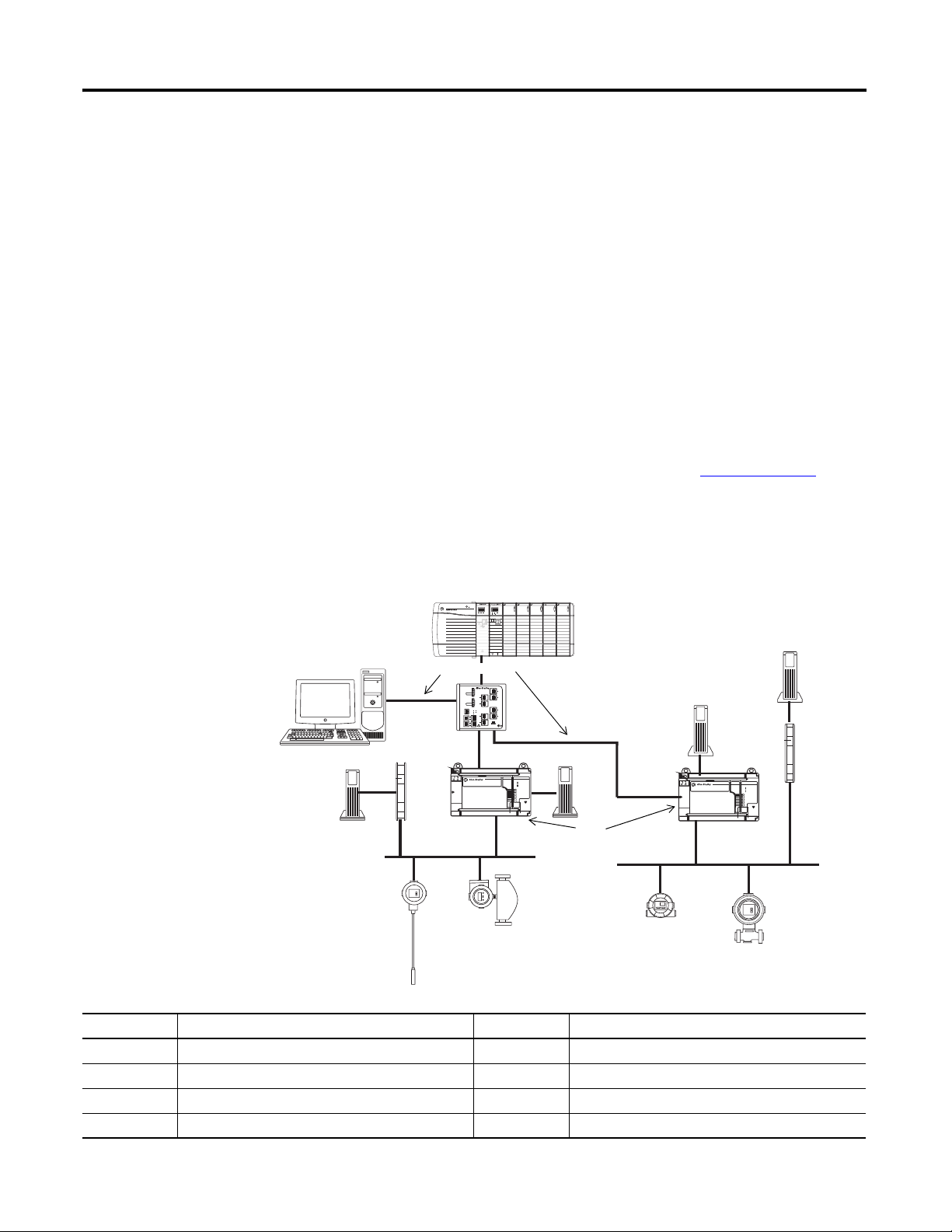
Figure 1 shows the RSFieldbus workstation connected directly over the
EtherNet/IP network to the ControlLogix chassis.
Figure 1 - EtherNet/IP and 1757-FFLD Linking Device Example
Item Description Item Description
1 ControlLogix controller with 1756-ENBT module 5 Power conditioner
2 Host computer and OPC server 6 1757-FFLD linking device
3 Stratix 8000 switch 7 Field devices
4 24V DC power supply T Network terminator
12 Rockwell Automation Publication 1757-UM012A-EN-P - July 2011
Page 13
FOUNDATION Fieldbus System Chapter 1
32072-M
1
2
3
HSE
ControlNet
4
5
6
7
H1
H1
TT
TT
ControlNet and 1757-FFLDC
Linking Device Example
The ControlNet network combines the functionality of an I/O network and a
peer-to-peer network, providing high-speed performance for both functions.
Devices can be scheduled for deterministic transfers of important data in
addition to unscheduled time intervals for non-critical information.
The 1757-FFLDC linking device has the option of being programmed for
scheduled, repeatable data transmissions on the Connection tab of the Module
Properties dialog box in RSLogix 5000 software. You must also run RSNetWorx
software to schedule the Logix Block to the network connection.
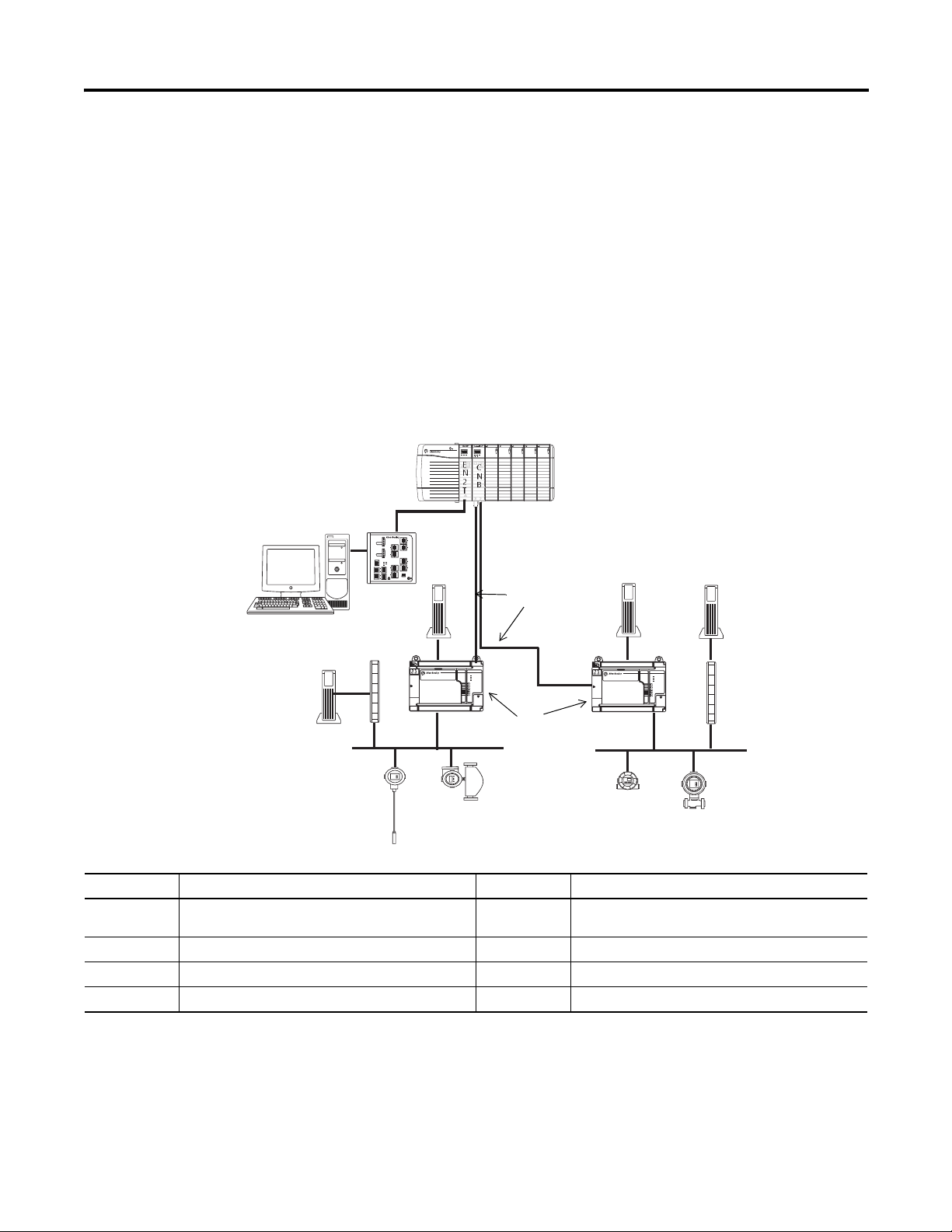
Figure 2 shows the RSFieldbus workstation bridged from Ethernet to the
ControlNet network via the ControlLogix chassis.
Figure 2 - ControlNet, Ethernet, and 1757-FFLDC Linking Device Example
DC OUTPUT
ANALOG INPUT
ANALOG INPUT
POWER
ST
01234567
89 10 111213 1415
ST
OKNETLINK
OK
HART
AB
E
C
N
N
2
B
T
ANALOG INPUT
DC INTPUT
ST
01234567
ST
01234567
ST
ST
01234567
01234567
FLT
01234567
FLT
01234567
O
O
K
O
K
K
89 10 111213 1415
89 10 111213 1415
ST
ST
ST
89 10 111213 1415
ST
89 10 111213 1415
89 10 111213 1415
FLT
89 10 111213 1415
FLT
HART
HART
DIAGNOSTIC
DIAGNOSTIC
A
B
FOUNDATION Fieldbus
H1-1
H1-2
FOUNDATION Fieldbus
H1-3
Linking Device
H1-4
STATUS
WD0G
BATT
NS
MODE
A
B
FOUNDATION Fieldbus
H1-1
H1-2
FOUNDATION Fieldbus
H1-3
Linking Device
H1-4
STATUS
WD0G
BATT
NS
MODE
Item Description Item Description
1 ControlLogix controller with 1756-ENBT and
1756-CNB modules
5 Power conditioner
2 Host computer and OPC server 6 1757-FFLDC linking device
3 Stratix 8000 switch (optional) 7 Field devices
4 24V DC power supply T Network terminator
Rockwell Automation Publication 1757-UM012A-EN-P - July 2011 13
Page 14

Chapter 1 FOUNDATION Fieldbus System
RSFieldbus Software Features
RSFieldbus software, which is installed on the host workstation, is a
configuration tool for creating links, loops, and schedules.
The list of RSFieldbus software features includes the following:
• Configure a fieldbus network with devices.
• Create and edit function block control strategies.
• Integrate fieldbus data into ControlLogix software via the Logix Block.
• Download a configuration.
• Online monitoring and editing of fieldbus parameters.
• Online monitoring of control strategy links.
• Make fieldbus data available via an OPC server.
See Chapter 3 on page 27
for software procedures.
14 Rockwell Automation Publication 1757-UM012A-EN-P - July 2011
Page 15
RSFieldbus Software Basics
Toolbar
Menu Bar
Chapter
2
Introduction
Main Window
This section describes the windows in RSFieldbus software and some of the tool
features found in these windows.
If you want to start using RSFieldbus software immediately, go to Chapter 3
The table lists the software topics described in this section.
Topic Page
Main Window 15
Project Window 17
Fieldbus Window 18
Process Cell Window 19
Strategy Window 20
Communication Window (error log) 25
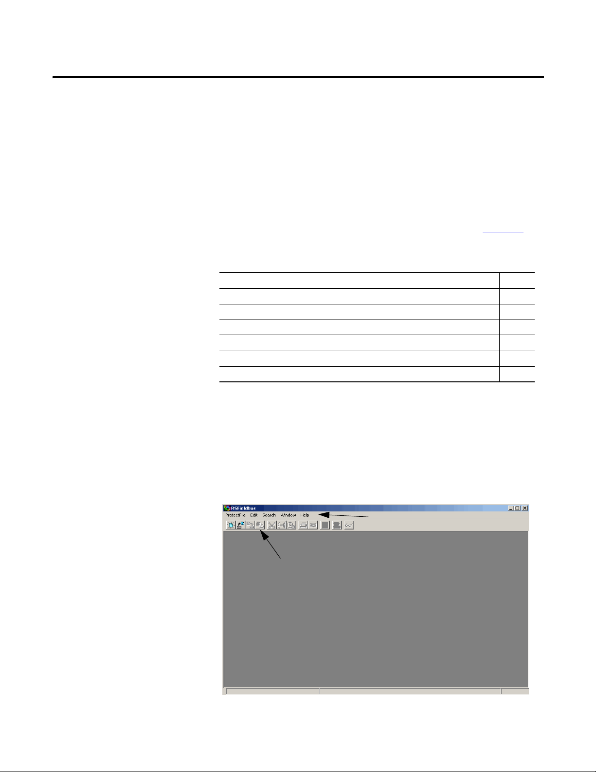
The menu bar contains actions specific to the selected window. These windows
open depending on which actions you have completed.
The Main window contains the main menu bar, a toolbar, and the windows
described in the following sections.
.
Figure 3 - RSFieldbus Main Window
Rockwell Automation Publication 1757-UM012A-EN-P - July 2011 15
Page 16
Chapter 2 RSFieldbus Software Basics
TIP
To open the Main window, you must start RSFieldbus software.
See page 28
for procedures.
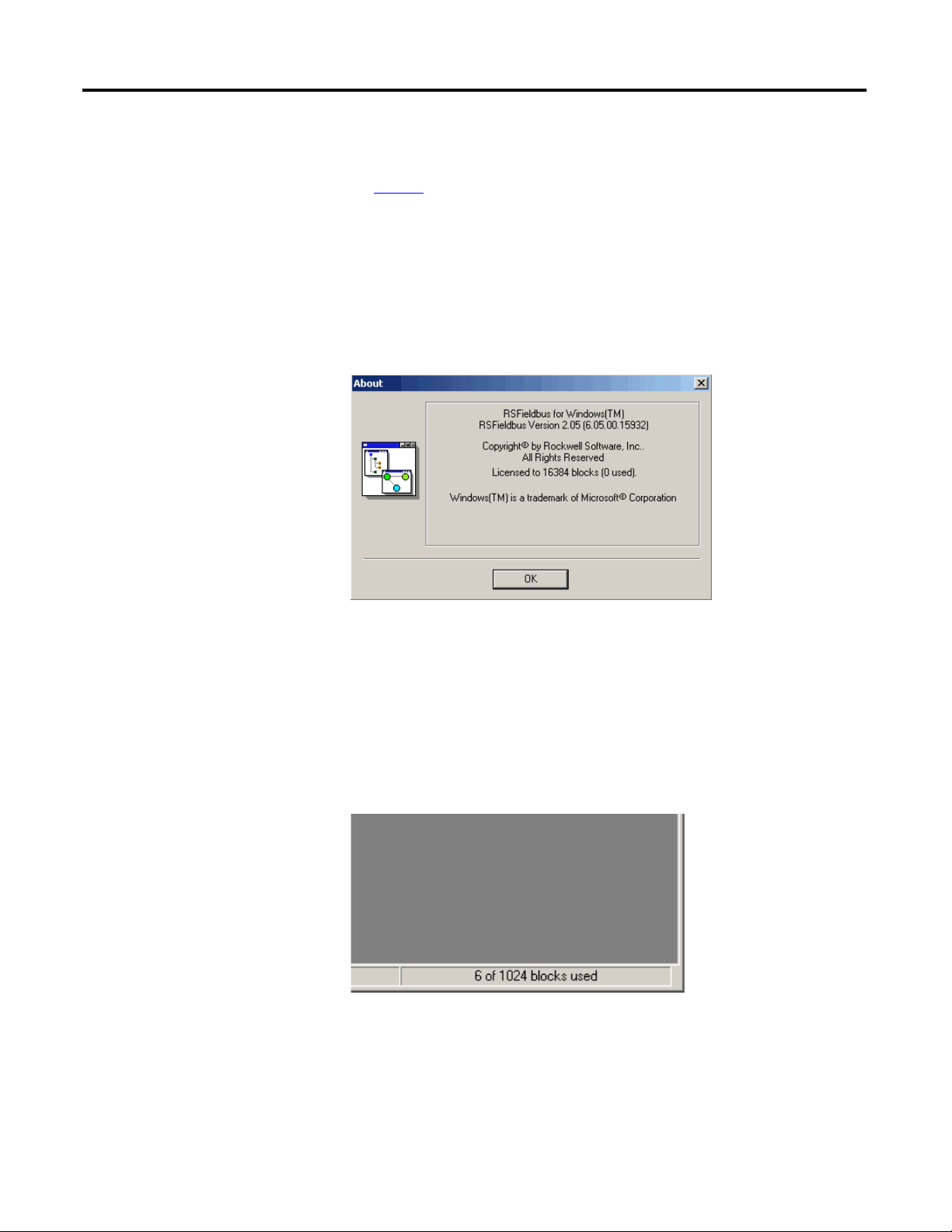
Licensed Blocks
From the Help menu, choose About to determine how many blocks you have
licensed.
The licensed block information appears below the Rockwell Software copyright.
When choosing an RSFieldbus license, keep in mind that a typical device
requires a minimum of three blocks (Resource, Transducer, and process
control) with an average of five blocks used. For example, a 64-block
RSFieldbus license will support approximately 21 devices. Any device
that requires more than three blocks will reduce the number of
supported devices.
The Main window contains a counter in the lower-right corner that lets you see
how many blocks you have in use.
16 Rockwell Automation Publication 1757-UM012A-EN-P - July 2011
Page 17
Main Window Toolbar
IMPORTANT
Toolbars can be moved anywhere on the screen by dragging and dropping
them to the desired location.
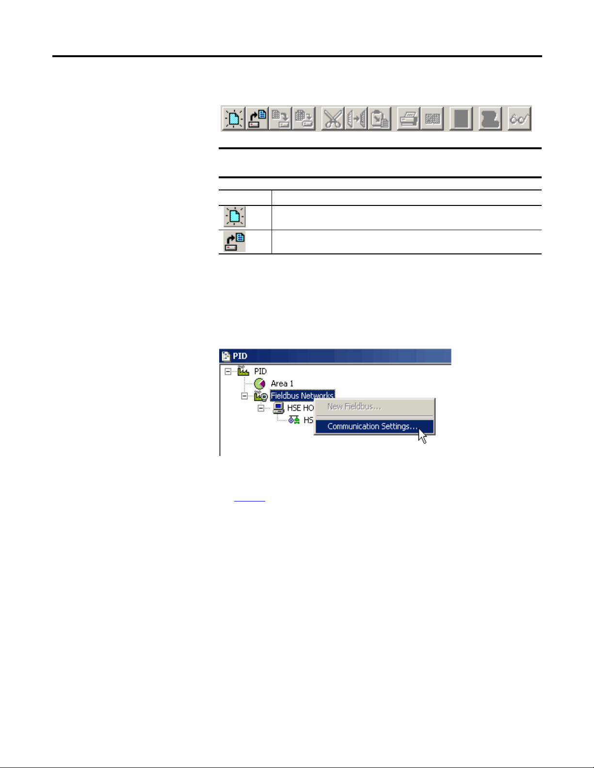
Toolbar Icon Description
Opens a new project or template. You must close all open projects or templates
before you can open another.
Opens an existing project or template. You must close all open projects or
templates before you can open another.
RSFieldbus Software Basics Chapter 2
Project Window
The Project window displays the project configuration, including the process cell
area (logical component), the Fieldbus network, individual fieldbuses, and
bridges. Right-clicking each item in this window opens a corresponding menu.
Figure 4 - Project Window
To open the Project window, you must open a new or existing project.
See page 31
for more information.
Rockwell Automation Publication 1757-UM012A-EN-P - July 2011 17
Page 18
Chapter 2 RSFieldbus Software Basics
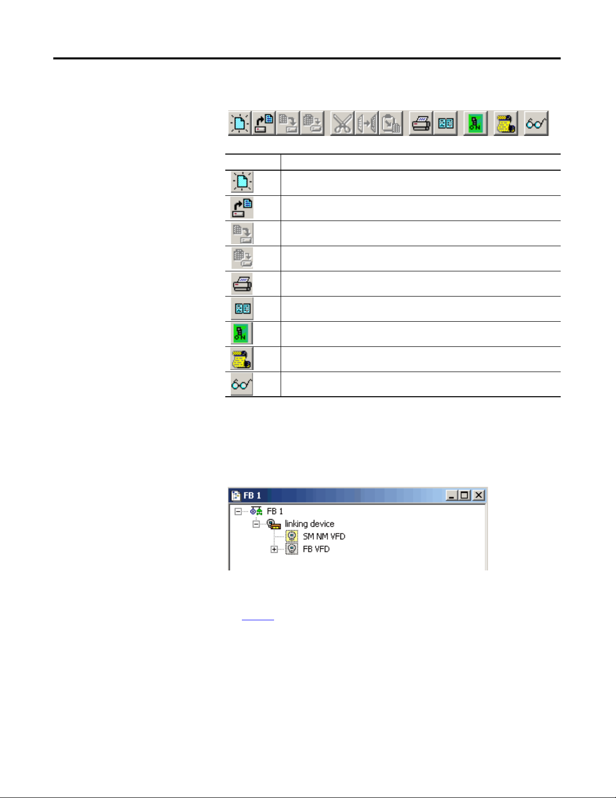
Project Window Toolbar
Toolbar Icon Description
Opens a new template. You must close any open templates before you can open
another.
Opens an existing template.
Saves the currently selected window.
Saves all open windows except template windows.
Prints the selected window.
Displays the print preview of the project.
Toggles the operation mode between online and offline.
Fieldbus Window
Opens the Communication window (Error Log).
Shows/hides detailed information about block types, block parameters, device
types and fieldbus macrocycles.
The Fieldbus window shows an individual fieldbus and all attached bridges,
devices, and blocks. This window serves as your H1 window, where you can
schedule blocks, links, and communication. Right-clicking each item in this
window opens a corresponding menu.
To open a Fieldbus window you must add a fieldbus (H1) and expand it.
See page 40
for more information.
18 Rockwell Automation Publication 1757-UM012A-EN-P - July 2011
Page 19

RSFieldbus Software Basics Chapter 2
Fieldbus Window Toolbar
The Fieldbus window toolbar contains the same buttons as the Project toolbar.
For descriptions of these buttons, see page 18
.
Process Cell Window
The Process Cell window shows an individual process cell and all attached
control modules and blocks. Right-clicking each item in this window opens a
corresponding menu.
To open a Process Cell window, you must add a process cell to the area and
expand it.
See page 43
for procedures.
Process Cell Window Toolbar
The Process Cell window toolbar contains the same buttons as the Project
toolbar. For descriptions of these buttons, see page 19
Rockwell Automation Publication 1757-UM012A-EN-P - July 2011 19
.
Page 20
Chapter 2 RSFieldbus Software Basics
Strategy Window
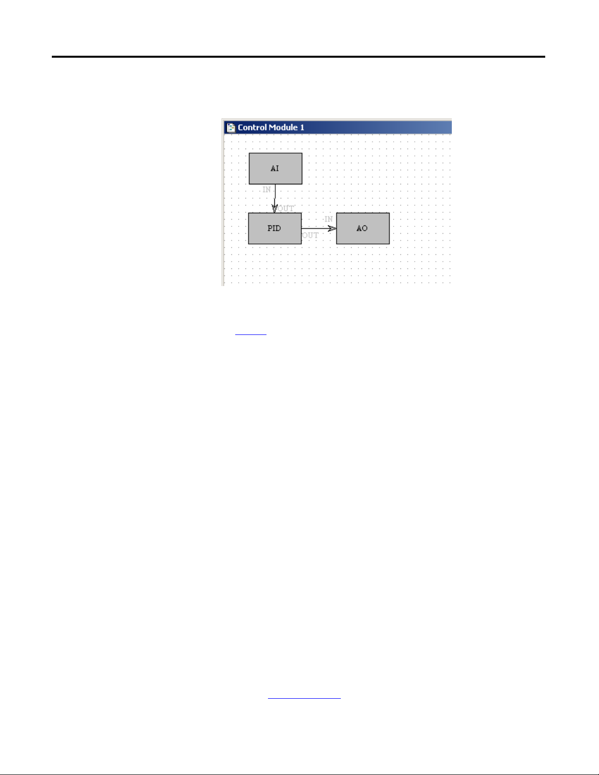
The Strategy window shows a graphic representation of the blocks, parameters,
and links in a control strategy.
To open the Strategy window, you must first create a control module.
See page 48
for more information.
Function Blocks and Parameters
Functions that can be performed by a device are represented as function blocks.
The set of function blocks available is dependent on the types of devices on your
fieldbus network. Function blocks contain algorithms and algorithm-controlling
parameters.
The standard blocks for fieldbus devices include the following:
• Analog Input (AI) • Discrete Output (DO)
• Analog Output (AO) • Proportional Derivative (PD)
• Discrete Input (DI) • Proportional Integral Derivative (PID)
You can change or set the action of a block by changing the settings of its
parameters. A block parameter that is written to the bus is referred to as an output
parameter. A block parameter that is receiving data is referred to as an input
parameter.
Blocks are linked, or connected, inside the devices. These links let you send data
from one block to the other block. Links connect blocks within the same device
and blocks that are in different devices.
For more information on function blocks, see Chapter 2 in the
FOUNDATION Fieldbus Design Considerations Reference Manual,
publication RSFBUS-RM001
.
20 Rockwell Automation Publication 1757-UM012A-EN-P - July 2011
Page 21
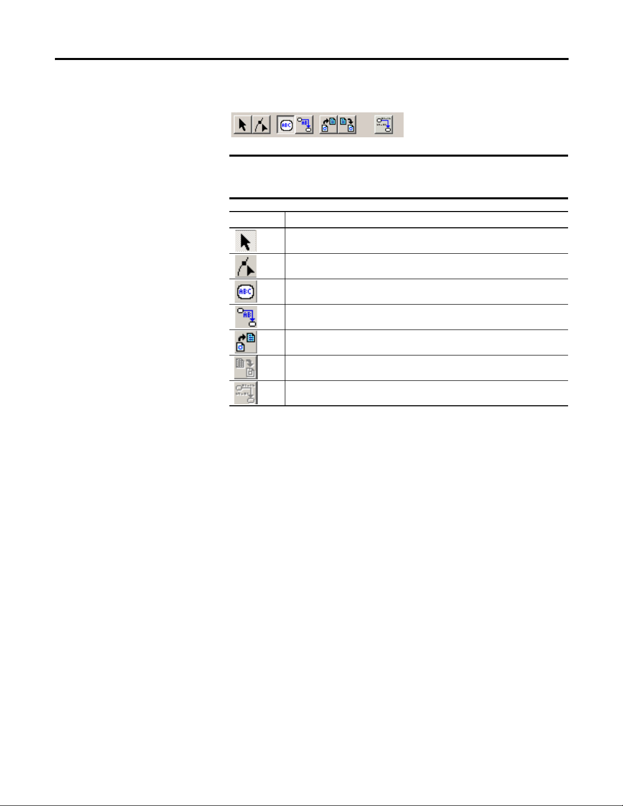
Strategy Toolbar
IMPORTANT
To view or hide any of the toolbars while the Strategy window is
selected, choose Tool Boxes on the Tools menu and select the toolbar
you want to view or hide.
Toolbar Icon Description
Selects items. To select more than one item, press Shift.
Used to modify block tags, links, link drawings and link connections.
Used to add blocks.
Creates links between blocks.
Imports templates into the strategy.
RSFieldbus Software Basics Chapter 2
Exports selected items in the strategy to a template file.
Used for online monitoring.
Rockwell Automation Publication 1757-UM012A-EN-P - July 2011 21
Page 22
Chapter 2 RSFieldbus Software Basics
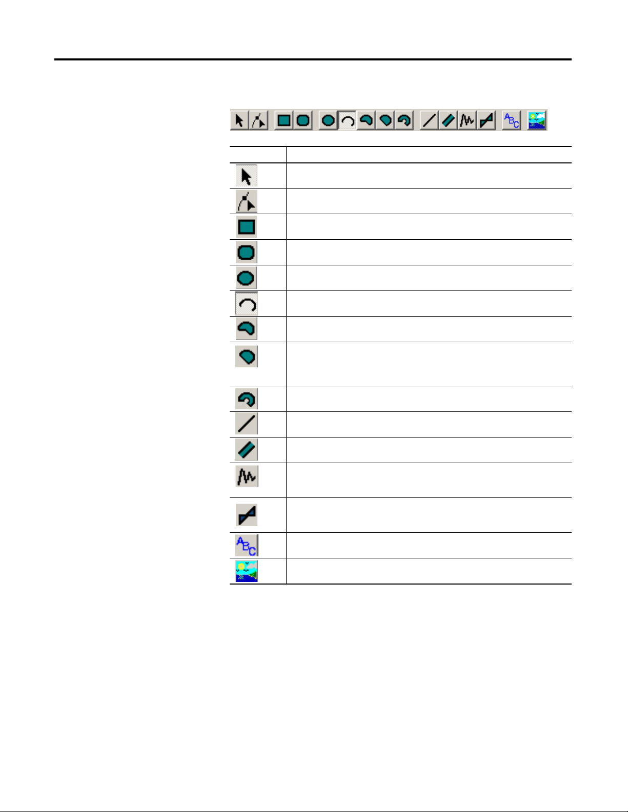
Drawing Toolbar
Toolbar Icon Description
Used to selects items. To select more than one item, press Shift.
Used to modify drawn objects.
Used to draw rectangles. To draw a square, press Shift.
Used to draw rounded rectangles. To draw a rounded square, press Shift.
Used to draw ellipses. To draw a circle, press Shift.
Used to draw arcs. To draw an arc whose height is equal to its width, press Shift.
Used to draw sections of a pie. To draw a section whose height is equal to its
width, press Shift. To expand the section beyond 90°, click Modify.
Used to draw a chord. To draw a section whose height is equal to its width, press
Shift. To draw a chord that is rounded on the top, click and drag to the right. To draw
a chord that is rounded on the bottom, click and drag to the left. To expand the
chord, click Modify.
Used to draw sections of a ring. To draw a section whose height is equal to its
width, press Shift. To expand the section beyond 90°, click Modify.
Used to draw a line. Press Shift to draw lines at 45° and 135°. Press Control to
draw lines at 0° and 90°.
Used to draw a pipe. Press Shift to draw pipes at 45° and 135°. Press Control to
draw pipes at 0° and 90°.
Used to draw a polyline. Left-click to begin the line and change its direction,
right-click to end the line. Press Shift to draw lines at 45° and 135°. Press Control to
draw lines at 0° and 90°.
Used to draw a polygon. Left-click to begin the shape and change its direction,
right-click to end the shape. Press Shift to draw lines at 45° and 135°. Press Control
to draw lines at 0° and 90°.
Used to add text to the drawing.
Lets you add a .bmp file to the drawing.
22 Rockwell Automation Publication 1757-UM012A-EN-P - July 2011
Page 23

RSFieldbus Software Basics Chapter 2
Alignment Toolbar
Do these steps to use the alignment buttons to align objects.
1. Select the object or objects you want to align.
2. Click one of the alignment buttons.
3. Click the anchor object (object to which you want to align the other
objects).
Toolbar Icon Description
Aligns the left side of the objects to the left side of the anchor.
Vertically aligns the center of the objects to the center of the anchor.
Aligns the right side of the objects to the right side of the anchor.
Aligns the top of the objects to the top of the anchor.
Horizontally aligns the center of the objects to the center of the anchor.
Aligns the bottom of the objects to the bottom of the anchor.
Places the center of the objects over the center of the anchor.
Adjusts the horizontal spacing evenly among the selected objects.
Adjusts the vertically spacing evenly among the selected objects.
Rockwell Automation Publication 1757-UM012A-EN-P - July 2011 23
Page 24
Chapter 2 RSFieldbus Software Basics
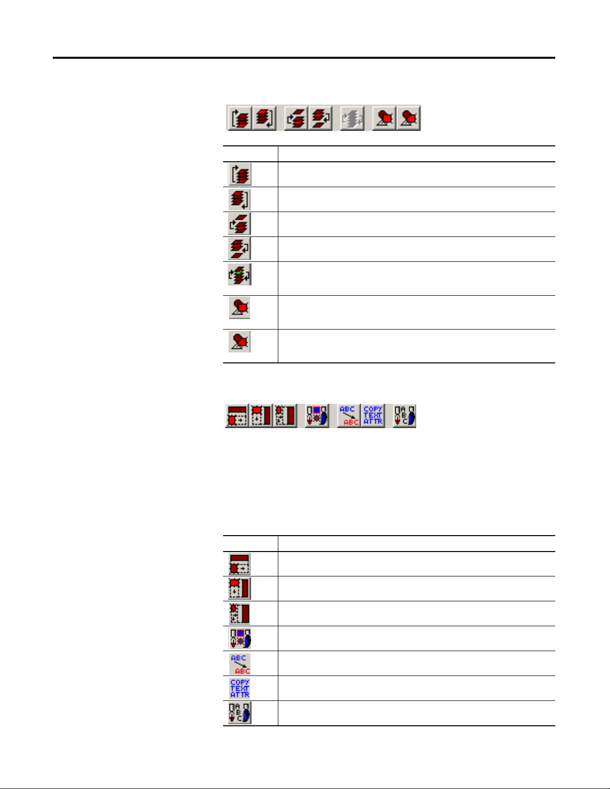
Ordering Toolbar
Toolbar Icon Description
Moves the selected object to the front.
Moves the selected object to the back.
Moves the selected object up one layer.
Moves the selected object down one layer.
Switches two objects in the order. Select the two objects that you want to switch,
then click the icon.
Moves the selected object in front of another. Select the object you want to move,
click the InFrontOf icon, then select the object in front of which you want it placed.
Moves the selected object behind of another. Select the object you want to move,
click the Behind icon, then select the object behind which you want it placed.
Copy Attributes Toolbar
Do these steps to use use the copy attributes buttons.
1. Select the object or objects you want to change.
2. Click one of the copy attributes buttons.
3. Click the anchor object (object whose attributes you want to copy).
Toolbar Icon Description
Copies the anchor’s width.
Copies the anchor’s height.
Copies the anchor’s dimensions (width and height).
Copies the anchor’s line and fill colors.
Copies the anchor’s font and font color.
Copies the anchor’s text attributes (font, size and color).
Sets the selected object’s attributes as default (line and fill color, text font and size).
24 Rockwell Automation Publication 1757-UM012A-EN-P - July 2011
Page 25
RSFieldbus Software Basics Chapter 2
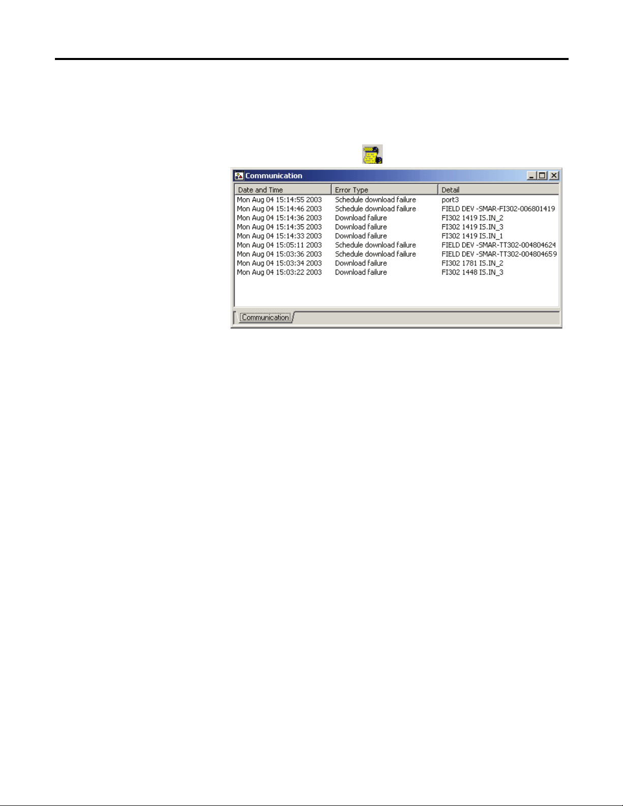
Communication Window
(error log)
The Communication window shows all errors in the current project.
Do these steps.
1. Click the Error Log icon
2. To delete individual entries, right-click the date and time of the desired
entry and choose Delete.
3. To delete all entries, right-click anywhere in the log and choose Clear Log.
to open the Communication window.
Rockwell Automation Publication 1757-UM012A-EN-P - July 2011 25
Page 26

Chapter 2 RSFieldbus Software Basics
Notes:
26 Rockwell Automation Publication 1757-UM012A-EN-P - July 2011
Page 27

Chapter
IMPORTANT
Create an RSFieldbus Software Project
3
Introduction
This section describes procedures for creating a fieldbus project by using the
RSFieldbus configuration software.
Projects contain both a physical and logical component. The physical component
contains the project hardware and the logical component contains the function
blocks and algorithms that are used to control the project. Projects can be started
from either component.
You must have RSFieldbus software installed on the computer that will
be used as the host server.
In addition, you need all the device description (DD) and capabilities files
to configure your fieldbus devices. There is a DD file for each device type
provided by the manufacturer. The capabilities file, which has a
.cff extension, is located within the DD files.
The table lists the main topics described in this section.
Topic Page
Initiate a Fieldbus Project 28
Create the Physical Component 31
Create the Logical Component 43
Create a New Strategy 48
Use Tools for Function Block Characterization 55
Design Templates 59
Use the HSE Network Setup Tool 63
Add Device to the FFLDC ControlNet Setup Tool 63
Rockwell Automation Publication 1757-UM012A-EN-P - July 2011 27
Page 28
Chapter 3 Create an RSFieldbus Software Project
STATUS
WDOG
BATT
NS 1
MODE
H1
H1
H1
H1
H1-1
H1-2
H1-3
H1-4
FOUNDATION Fieldbus
FOUNDATION Fieldbus
Linking Device
TT
HSE Protocol
(through ControlNet
or Ethernet)
1
2
4
3
5
2
H1 Network
43733
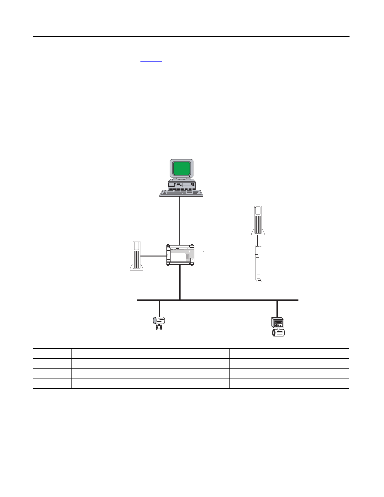
Initiate a Fieldbus Project
Figure 5 shows an example of a typical fieldbus system. The HSE protocol is
established during the initial download of the RSFieldbus software. Data is
transferred and stored to the workstation through the Ethernet or ControlNet
networks depending on your application requirements and the selected
linking device.
The 1757-FFLD linking device connects field devices on H1 segments to Logix
controllers by using an Ethernet transmission. The 1757-FFLDC bridges data
flow between H1 segments on the ControlNet network.
Figure 5 - Fieldbus System Example
Item Description Item Description
1 RSFieldbus workstation 4 Power conditioner
2 24V DC power supply 5 Field devices
3 Linking device - 1757-FFLD or 1757-FFLDC T Network terminator
You must have at least one power conditioner per power supply on the H1 line,
and two terminators; one each at opposite ends of the bus, as shown in
Figure 9.
Refer to the FOUNDATION Fieldbus Design Considerations Reference
Manual, publication RSFBUS-RM001
28 Rockwell Automation Publication 1757-UM012A-EN-P - July 2011
, for additional system requirements.
Page 29
Create an RSFieldbus Software Project Chapter 3
IMPORTANT
TIP
Do these steps to initiate an RSFieldbus project.
1. To start the RSFieldbus software program, choose
Start>Programs>Rockwell Software>RSFieldbus>RSFieldbus.
The RSFieldbus Main window appears.
There is a choice for a demo license that lets you create a limited number of
function blocks. In the non-demo mode, you must activate a license.
To check how many blocks are licensed on your system, choose About on
the Help menu.
When choosing an RSFieldbus license, keep in mind that a typical device
requires a minimum of three blocks (Resource, Transducer, and process
control), with an average of five blocks used. For example, a 64-block
RSFieldbus license will support approximately 21 devices. Any device
that requires more than three blocks will reduce the number of
supported devices.
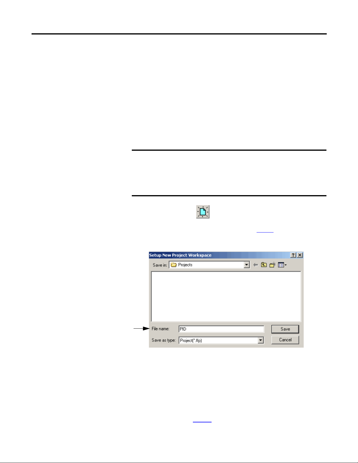
2. Click the New icon and choose Project.
To open an existing project, see page 31 for procedures.
The Setup New Project Workspace dialog box appears.
3. Type a project name for the File name.
Our example shows PID. The ‘.ffp’ extension for saved projects denotes
FOUNDATION Fieldbus project.
4. Click Save.
The Project Window appears.
See an example on page 30
Rockwell Automation Publication 1757-UM012A-EN-P - July 2011 29
.
Page 30
Chapter 3 Create an RSFieldbus Software Project
IMPORTANT
Define the Server
When a new project is created, your computer is defined as the HSE host and the
bridge from the RSFieldbus software to your HSE fieldbus devices. The HSE
host also has been designated as the Link Master.
Do these optional steps to make sure the server path is correct to store the field
device data. Otherwise, proceed to Create a New Bridge (linking device) on
page 31.
1. In the Setup New Project Workspace dialog box, double-click the file name
with the .ffp extension.
In our example, it would be PID.ffp.
You cannot have two computers running RSFieldbus software
with the HSE host defined locally and connected on the same
network.
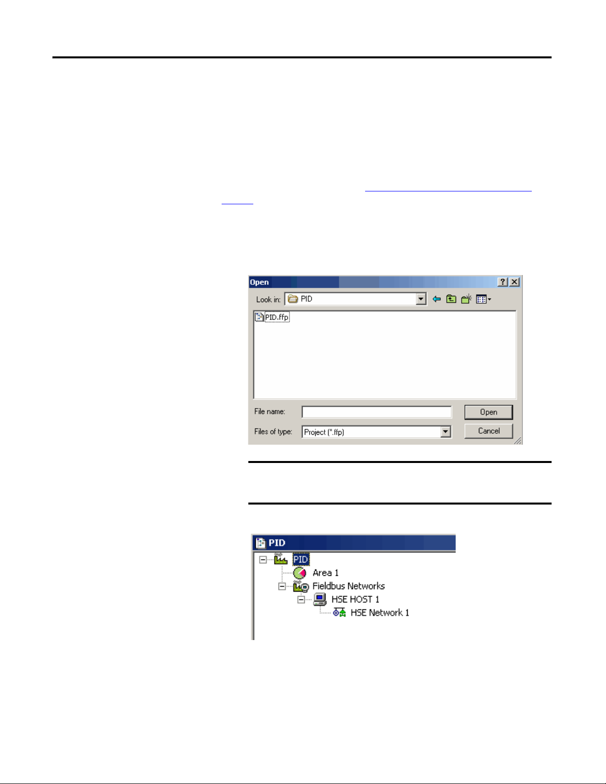
The Project window appears.
• Area 1 contains the process cell that contains the function block logic.
This is where the logical component of the project is created.
• Fieldbus Networks is where the physical bridges and devices are found.
This is where the physical component of the project is created.
30 Rockwell Automation Publication 1757-UM012A-EN-P - July 2011
Page 31
Create an RSFieldbus Software Project Chapter 3
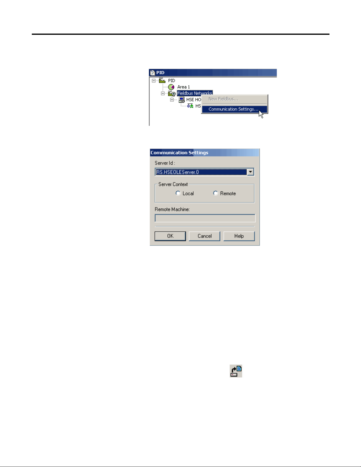
2. In the Project window, right-click Fieldbus Networks and choose
Communication Settings.
The Communication Settings dialog box appears.
Create the Physical
Component
3. Verify the settings are the same as the dialog box shows, and click OK.
Do these steps to add bridges and devices to your project.
Create a New Bridge (linking device)
This section defines the linking device as the bridge from HSE to your H1 field
devices. You can add a bridge in either the Project window or the HSE window,
this example shows the former.
1. To open an existing project, choose Open from the ProjectFile menu.
You also can click the Open icon .
2. In the Open dialog box, select your project by double-clicking it.
Rockwell Automation Publication 1757-UM012A-EN-P - July 2011 31
Page 32
Chapter 3 Create an RSFieldbus Software Project
IMPORTANT
The Project window appears.
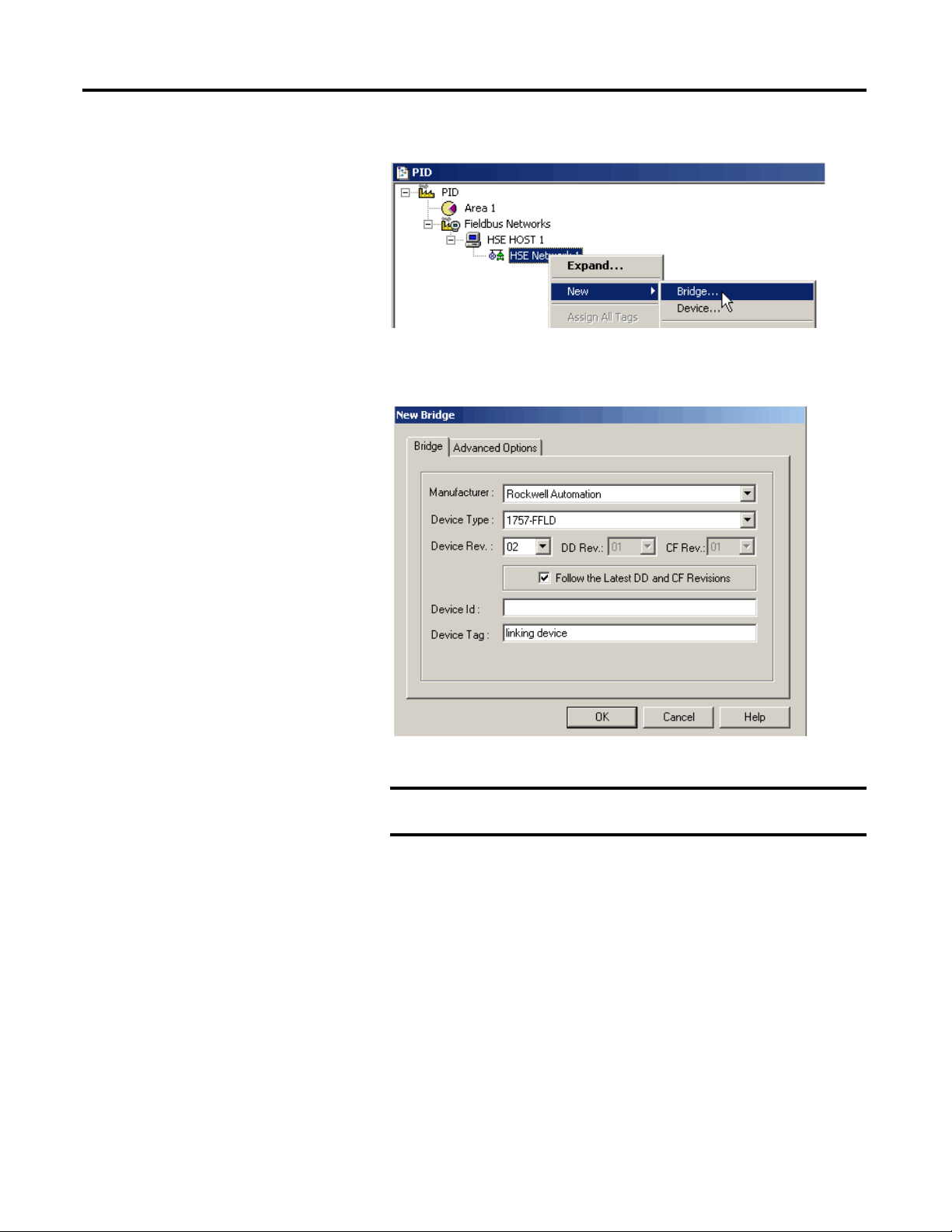
3. Right-click HSE Network 1 and choose New>Bridge.
The New Bridge dialog box appears.
4. Select the settings for the linking device you are using in the application.
Be sure that the Device Rev and DD Rev match the revision of
linking device and revision of firmware that you are using.
5. Type a tag name for the bridge in the Device Tag box.
If you do not enter a tag the default tag is Bridge_#.
You must give each device a tag name to differentiate between devices on
the same H1 segment. Tags cannot include a ‘.’ (period). If a separator is
necessary, we suggest using an ‘_’ (underscore). Spaces are allowed, but
not recommended.
Observe that the ‘Follow the Latest DD and CF Revisions’ box is checked.
You need the device support files to configure a device. A device
description (DD) file contains parameters for each device type. A
capabilities file (CF) contains the resources available for creating function
block applications.
32 Rockwell Automation Publication 1757-UM012A-EN-P - July 2011
Page 33
Create an RSFieldbus Software Project Chapter 3
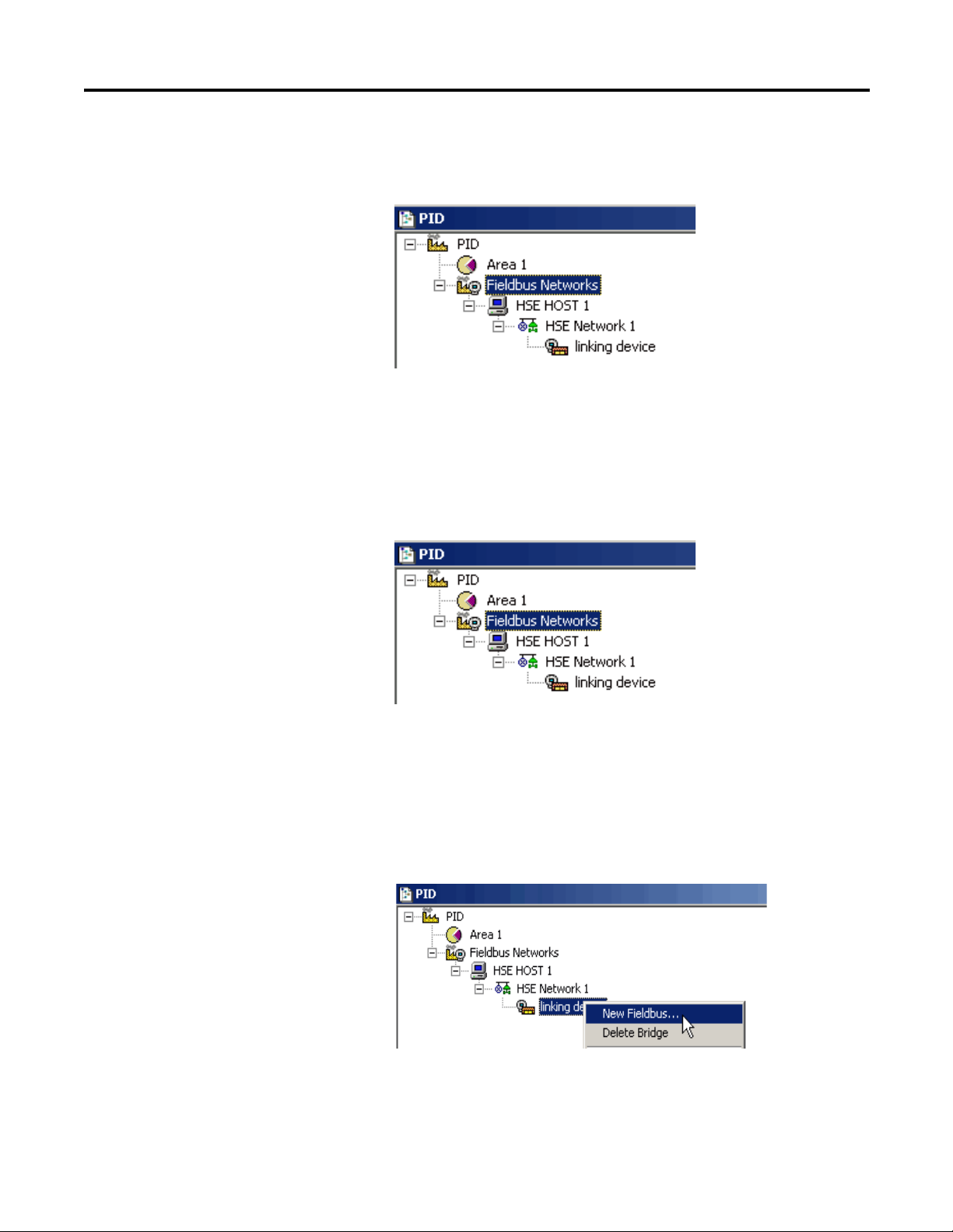
6. Click OK.
The linking device is added to the HSE Host.
7. Click the Advanced Options tab.
Use the default of ‘Creation based on Default Template.’ Clear the box to
make your own selections.
8. Click OK.
The linking device is added to the HSE Host.
Create a New Fieldbus (H1) Link
Do these steps to associate the fieldbus with the H1 segment.
1. In the Project window, right-click the linking device and choose
New Fieldbus.
Rockwell Automation Publication 1757-UM012A-EN-P - July 2011 33
Page 34
Chapter 3 Create an RSFieldbus Software Project
IMPORTANT
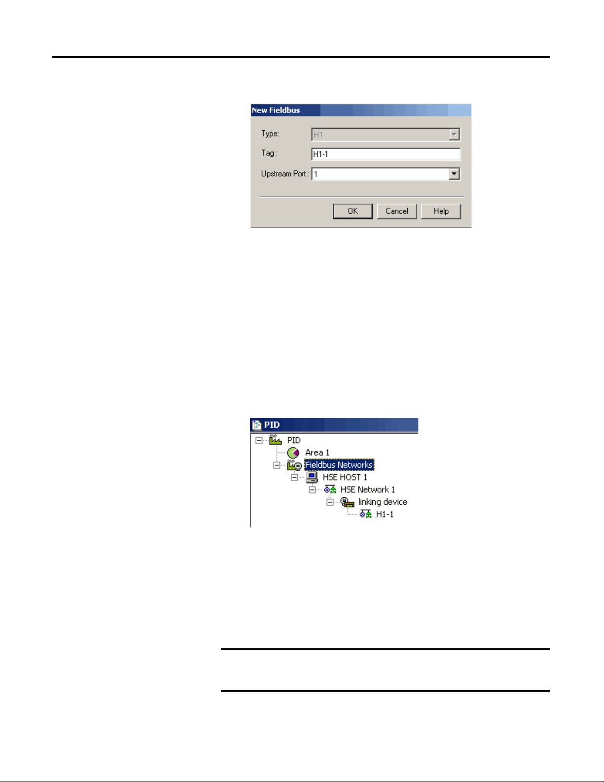
The New Fieldbus dialog box appears.
2. Enter a tag name for the H1.
If you do not enter a tag, the default tag is Fieldbus #.
The 1757-FFLD linking device has two or four H1 ports depending on
your system requirements. We recommend that you name each tag
according to its port number. For example, H1-1 indicates that this is
Upstream Port 1.
3. Select the Upstream Port (H1 port) on the linking device to which the H1
segment is connected.
4. Click OK.
The Fieldbus (H1) is added to the Project.
Set the Macrocycle
RSFieldbus software automatically calculates the macrocyle time for a fieldbus
device to send and receive data. In many cases, you will have to increase the
macrocycle time to provide more time for background traffic, such as
downloading, monitoring, assigning tags, and other commissioning tasks.
If the macrocycle time is too short, you will receive a failure when you
attempt to download and you may not be able to add devices to
the network.
34 Rockwell Automation Publication 1757-UM012A-EN-P - July 2011
Page 35
Create an RSFieldbus Software Project Chapter 3
TIP
To facilitate commissioning activities, the macrocycle can be set to
1000… 2000 ms. After all the devices are commissioned and operating and the
strategy is downloaded, the macrocycle can be reduced.
If more unscheduled time is needed, increase the macrocycle. The unused
scheduled time will be used for the unscheduled activities.
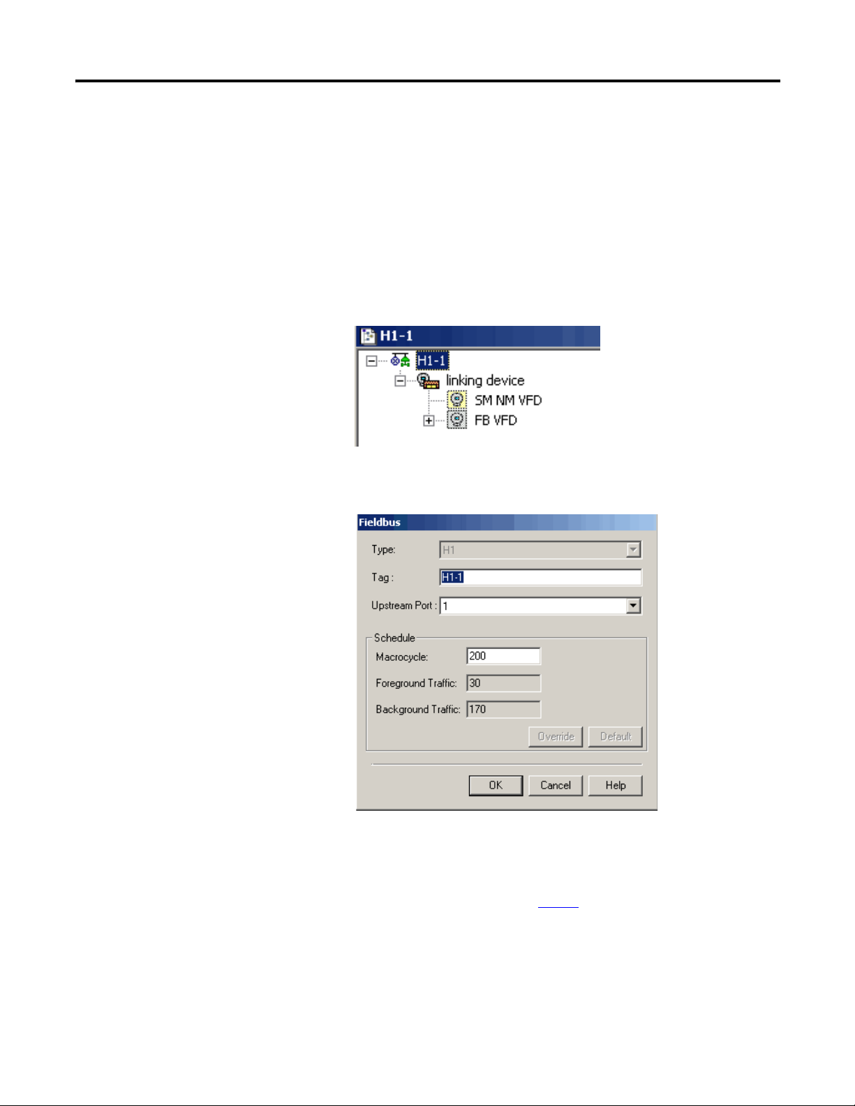
1. In the Project window, double-click H1-1 (or whatever you named
the tag for the H1 link).
The Fieldbus window appears.
2. Right-click H1-1 and choose Attributes.
The Fieldbus attributes dialog box appears.
3. Type a macrocycle time (in milliseconds) and click OK.
The new macrocycle time will not take effect until the H1 segment
is downloaded.
To set a stale count, see page 46
.
Rockwell Automation Publication 1757-UM012A-EN-P - July 2011 35
Page 36
Chapter 3 Create an RSFieldbus Software Project
Create a New Device
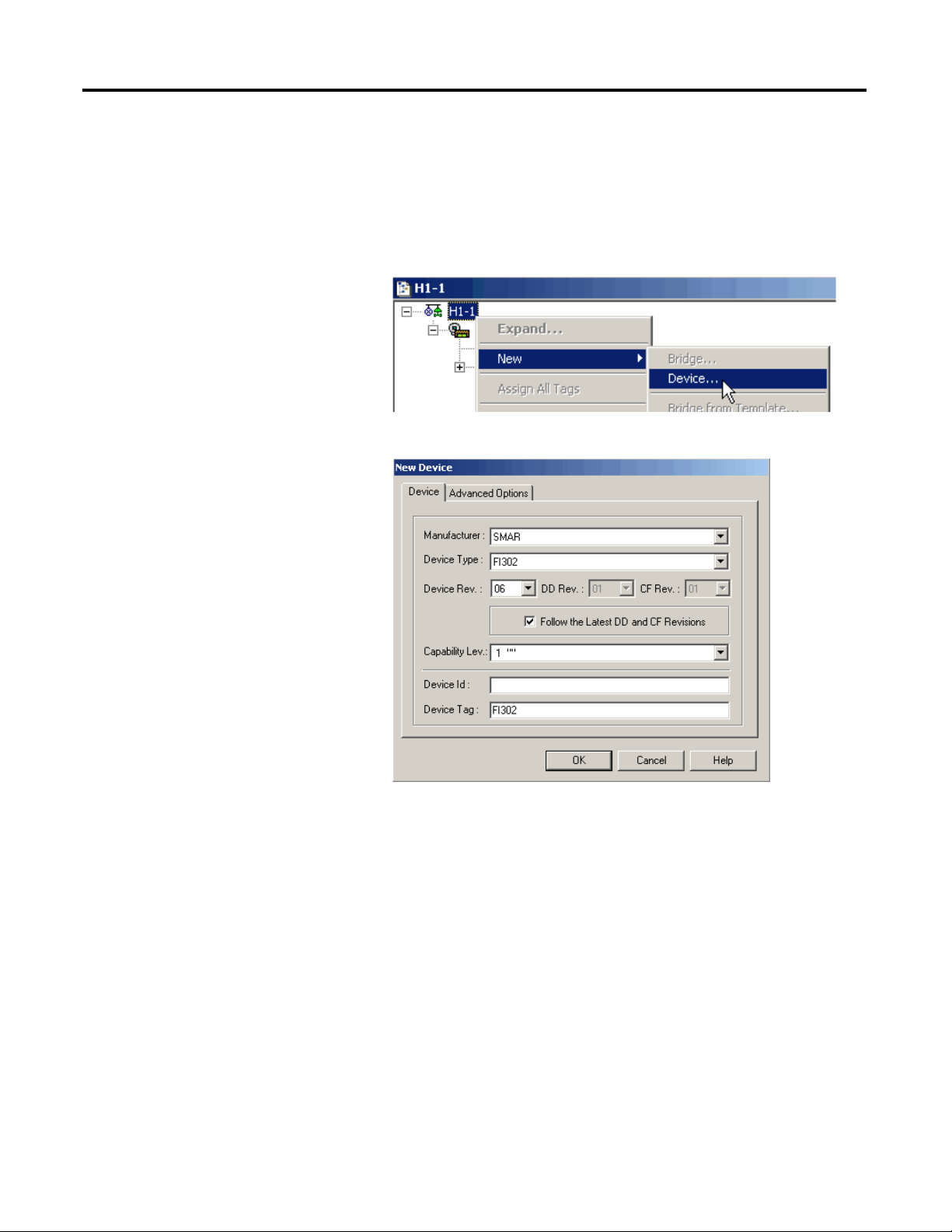
Do these steps to add devices to the H1 network.
1. In the Fieldbus (H1) window, right-click the H1 icon and choose
New>Device.
The New Device dialog box appears.
36 Rockwell Automation Publication 1757-UM012A-EN-P - July 2011
Page 37

Create an RSFieldbus Software Project Chapter 3
IMPORTANT
2. Configure the device by entering information in the New Device
dialog box.
Field Description
Manufacturer Choose a manufacturer from the
Device Type Choose a device type from the
Device Rev Choose the device revision.
Capability Lev Defaults to the capability of the instrument.
Device Tag Type a Device Tag. If you do not enter a tag,
pull-down menu.
pull-down menu.
IMPORTANT: The DD and CF values default
to the latest revisions in the device support
files if the ‘Follow the Latest DD and CF
Revisions’ box is checked.
If the DD and CF revisions do not match your
device firmware, clear the box and choose
the correct revisions.
the default tag is Device_#.
If the correct revisions are not listed, the correct DDs need to be
imported. Refer to Device Support in the appendix.
If you do not match the correct revisions with your device
firmware, you receive a warning on download. Incorrect DD files
will cause download failures, which results in the project
configuration not functioning for that device.
3. Repeat steps 1
and 2 for additional devices.
4. Click the Advanced Options tab.
Use the default of ‘Creation based on Default Template’.
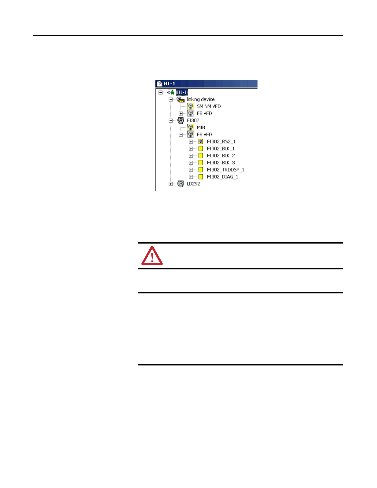
5. Click OK.
Rockwell Automation Publication 1757-UM012A-EN-P - July 2011 37
Page 38
Chapter 3 Create an RSFieldbus Software Project
IMPORTANT
Devices are added to the H1 and a set of function blocks are added as well.
This set includes a Transducer and Resource block, and may include others
depending on the device.
Change Device Class to Link Master
This procedure enables you to configure the device class of all the devices in the
project at the same time. You must be online for this task.
ATTENTION: During this procedure, control of the associated devices
and anything linked to them will be lost.
Do these steps to configure the device class to a Backup LAS.
We recommend that you open the Live List to verify the current device
class of the devices on the network.
If a device is added to the project that is already configured as a Link
Master, you must complete this procedure to keep that configuration. If
you do not add the device to the Backup LAS list it will be returned to
Basic when you complete the device configuration for other devices.
Also, if you do not complete this procedure for preconfigured Link
Masters, there will be a mismatch error during download and the project
will not be downloaded.
38 Rockwell Automation Publication 1757-UM012A-EN-P - July 2011
Page 39
Create an RSFieldbus Software Project Chapter 3
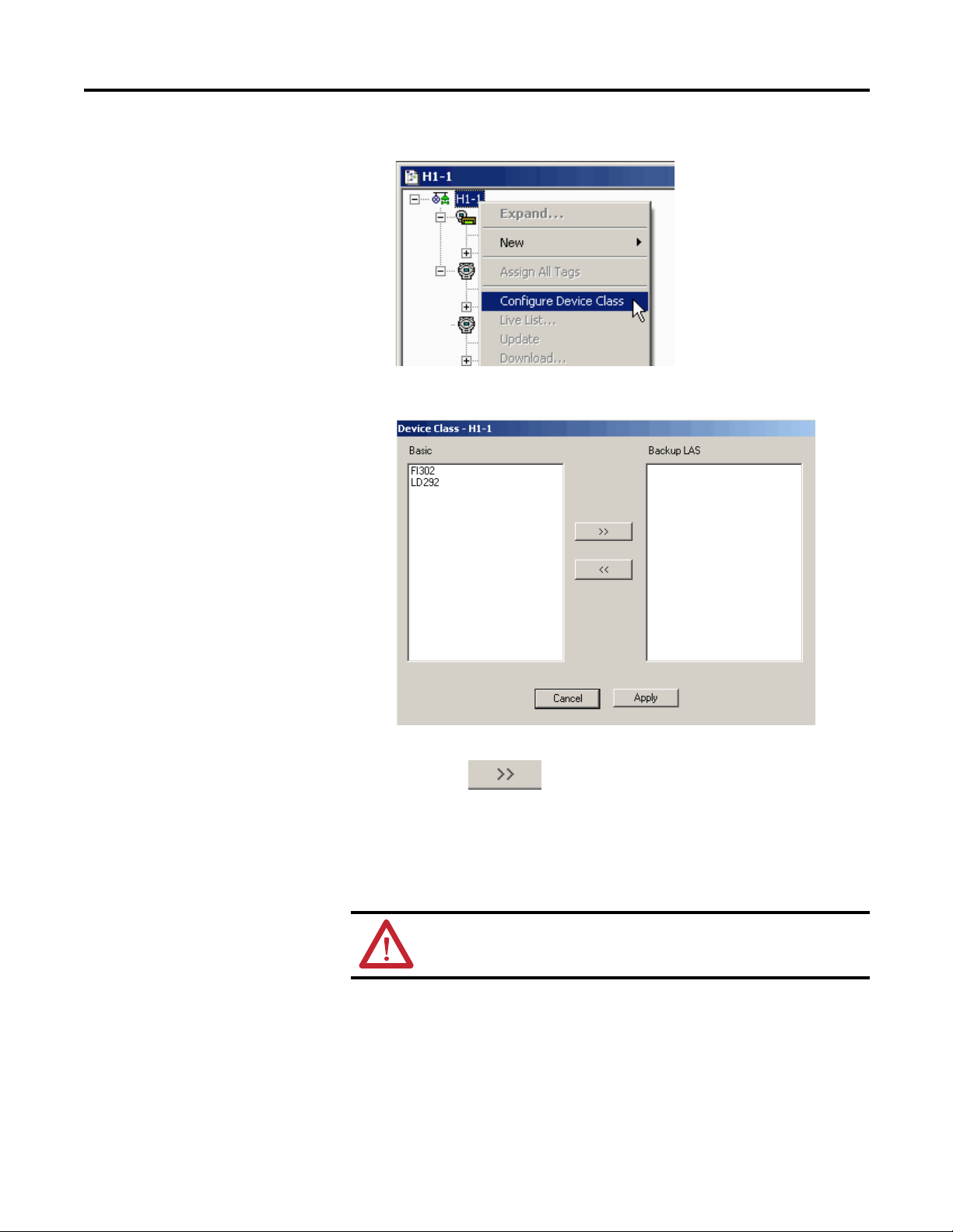
1. Right-click the H1 icon and choose Configure Device Class.
The Device Class dialog box appears.
2. Select the device that you want to change to a Backup LAS and click the
right arrow .
3. Repeat for any other devices that you want to change to a Backup LAS.
4. Click Apply.
Change Device Class to Basic
ATTENTION: During this procedure, control of the associated devices
and anything linked to them will be lost.
Do these steps to change the device class of a device from Backup LAS to Basic.
1. Right-click the H1 icon and choose Configure Device Class.
The Device Class dialog box appears.
Rockwell Automation Publication 1757-UM012A-EN-P - July 2011 39
Page 40
Chapter 3 Create an RSFieldbus Software Project
2. Select the device that you want to change to a Basic and click the left arrow
.
3. Repeat for any other devices that you want to change to a Basic.
4. Click Apply.
Edit Attributes
To change or delete an ID or tag for an H1, device, or bridge, do these steps.
1. To edit a tag, double-click the corresponding icon in the H1 window.
An Attributes dialog box appears.
2. Make the necessary changes, and then click OK.
3. To delete a tag, right-click the corresponding icon and choose
Delete Device.
Create a New Function Block
This section explains how to add function blocks to a device in the
physical component.
See page 47
1. In the Fieldbus (H1) window, expand the device by clicking .
2. Right-click the FB VFD icon and choose New Block.
if you are adding a function block in the logical component.
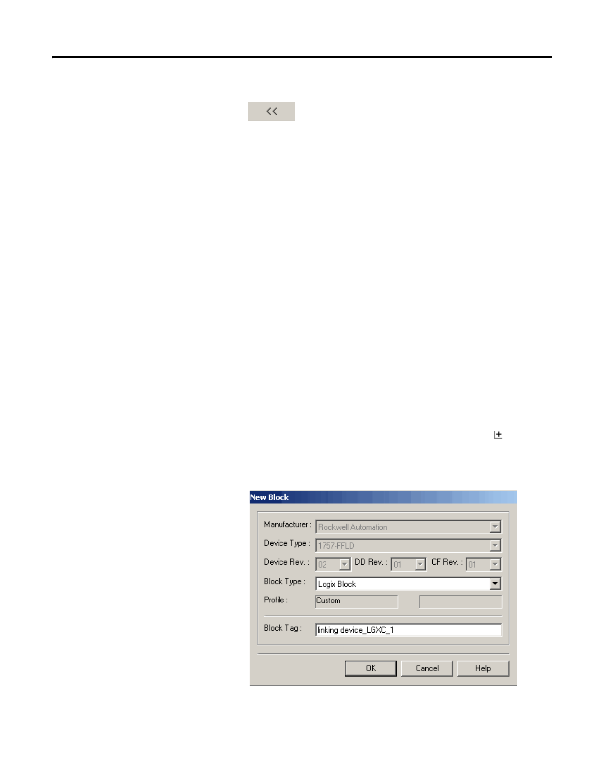
The New Block dialog box appears.
40 Rockwell Automation Publication 1757-UM012A-EN-P - July 2011
Page 41
Create an RSFieldbus Software Project Chapter 3
3. From the Block Type pull-down menu, choose a block type tag.
ATTENTION: Be sure the tags used in your RSFieldbus projects on
the same HSE Server are unique or your project may not function
properly.
Tags cannot include a ’.’ (period). If a separator is needed, use an
’_’ (underscore). Spaces are allowed, but not recommended.
If you do not enter a tag, a tag is generated according to the settings in the
Preference dialog box (Block tab) on the ProjectFile menu.
4. Type a name for the block tag.
5. Click OK.
The block is added to the device.
6. If you need to edit the block tag, right-click the block icon and
choose Attributes.
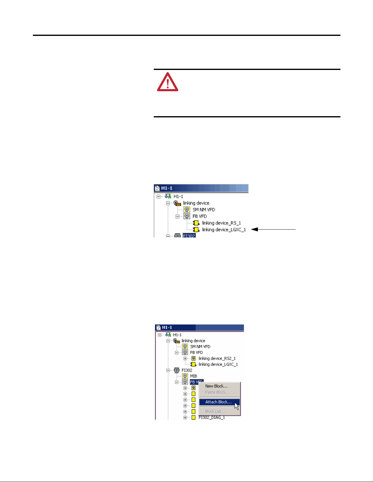
Attach Block to a Device
Function blocks that have been added to the logical component can be attached
to a device in the physical component.
1. In the Fieldbus (H1) window, right-click the FB VFD icon in the device to
which the block is being attached, and choose Attach Block.
The Attach Block dialog box appears.
Rockwell Automation Publication 1757-UM012A-EN-P - July 2011 41
Page 42

Chapter 3 Create an RSFieldbus Software Project
IMPORTANT
2. Choose the desired block and click OK.
The block is added to the physical component.
Detach a Block from a Device
Do these steps to remove a function block from a device.
1. In the Fieldbus (H1) window, right-click the desired block and choose
Detach Block.
2. Click Yes at the warning message.
The function block is removed from the device.
If the block is attached to a control module, it remains attached to
the control module after being detached from a device. The block
can be attached to a different device.
Tag Search
Do these steps to search and locate a tag in your configuration.
1. From the Search menu, choose Find.
The Find Tags dialog box appears.
Use the Device tab to search for a device or bridge tag or use the Block tab
to search for a block.
42 Rockwell Automation Publication 1757-UM012A-EN-P - July 2011
Page 43
Create an RSFieldbus Software Project Chapter 3
2. Enter the tag in the Tag to Find box.
You also can click the tag in the Tags list.
The location of the tag appears in the Fieldbus Networks Location section.
3. Click OK.
The tag is highlighted in your configuration.
Create the Logical
Component
This section describes how to create a logical component to your
fieldbus application.
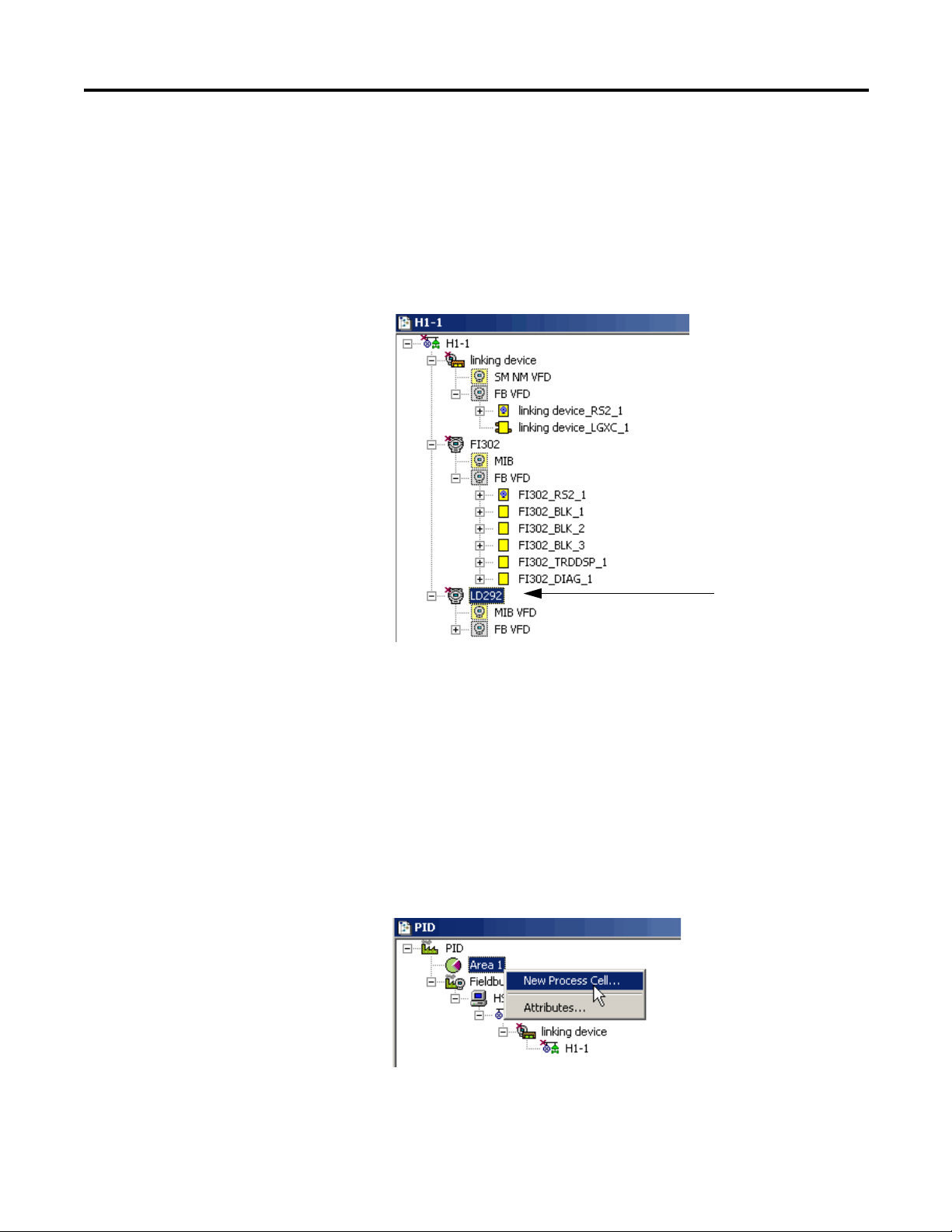
Create a New Process Cell
Do these steps to create a process cell to administer function block logic.
1. In the Project window, right-click the Area 1 icon and choose
New Process Cell.
Rockwell Automation Publication 1757-UM012A-EN-P - July 2011 43
Page 44

Chapter 3 Create an RSFieldbus Software Project
The Process Cell dialog box appears.
2. Typ e a ta g nam e.
Our example is Process Cell 1.
3. Click OK.
The Process Cell is added to the project.
44 Rockwell Automation Publication 1757-UM012A-EN-P - July 2011
Page 45

Create an RSFieldbus Software Project Chapter 3
Create a New Control Module
Do these steps to add a control module to your project.
1. Right-click the Process Cell icon and choose Expand.
The Process Cell window appears.
2. Right-click the Process Cell icon and choose New Control Module.
The Control Module dialog box appears.
3. Typ e a ta g nam e.
Our example is Control Module 1.
4. Click OK.
The new (Pressure) Control Module is added to the Project.
Rockwell Automation Publication 1757-UM012A-EN-P - July 2011 45
Page 46

Chapter 3 Create an RSFieldbus Software Project
Set the Stale Count
Stale count is the number of macrocycles that elapse before a signal is sent to
indicate there has been no update of the link data.
Table 1 - Stale Count Examples
Macrocyle Stale Count Delay Before a Link Failure is Indicated via the Input
200 ms 10 2 s
1000 ms 10
(1) A more appropriate stale count for this example may be 3 or 4 seconds depending on the
application requirements.
(1)
Fault Bit or Quality/Status Data
10 s
Do these steps to change the stale count.
1. In the Process Cell window, right-click the control module icon and
choose Attributes.
The Control Module dialog box appears.
2. Enter a stale count value and click OK.
The Control Module is added to your configuration.
46 Rockwell Automation Publication 1757-UM012A-EN-P - July 2011
Page 47

Create an RSFieldbus Software Project Chapter 3
Create a Function Block in Logical Component
Follow the same procedures as documented on page 40, except make sure you add
the blocks in the Process Cell window.
An attached function block in the Process Cell will have a question mark until the
block is attached to a device.
Do these steps to attach a function block to a control module.
1. In the Process Cell window, right-click the control module to which the
block is being attached and choose Attach Block.
The Attach Block dialog box appears.
2. Select the desired block and click OK.
The block is added to the logical component.
Rockwell Automation Publication 1757-UM012A-EN-P - July 2011 47
Page 48
Chapter 3 Create an RSFieldbus Software Project
IMPORTANT
Create a New Strategy
This section explains how to create and maintain a control strategy. Each control
module has its own Strategy window. You can make change to a strategy in the
H1 and Process Cell windows.
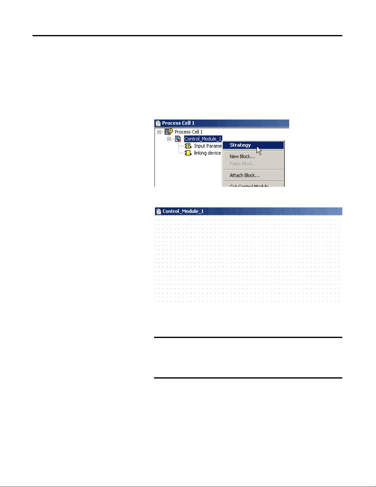
Do these steps to initiate a control strategy.
1. In the Process Cell window, right-click the control module icon and
choose Strategy.
The Strategy window appears.
The Strategy window is similar to graph paper to help you align the blocks
that are connected.
To initially set the default shape for your new strategy blocks
(rectangle, rounded rectangle, ellipse), see the Strategy tab on
the Preferences dialog box under the ProjectFile menu. Once
blocks are added to the strategy, you cannot change them to a
different shape.
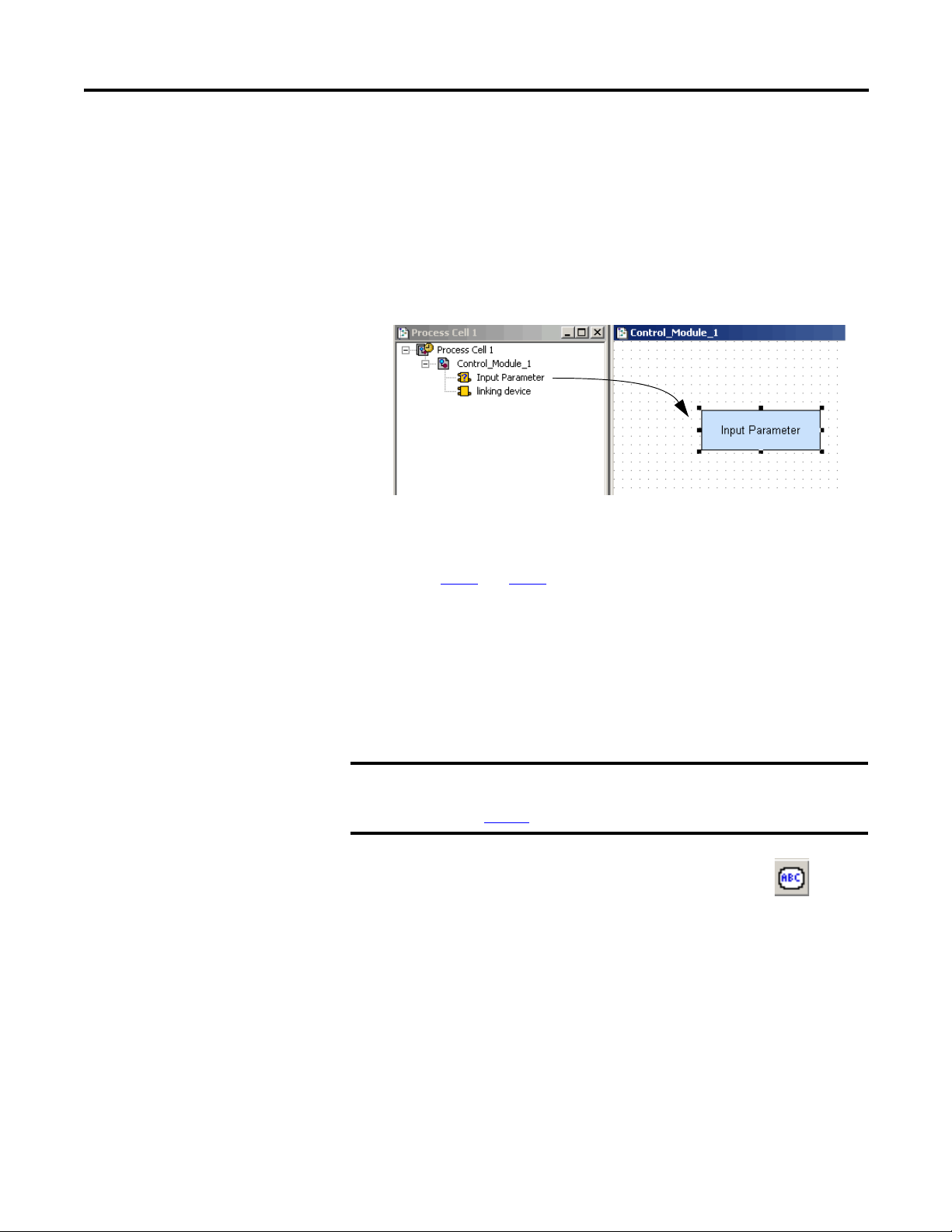
There are three ways to add blocks to the Strategy window:
• Drag blocks to the Strategy window from the Process Cell window or
the Fieldbus (H1) window.
• Create new blocks in the Strategy window.
• Import a template.
48 Rockwell Automation Publication 1757-UM012A-EN-P - July 2011
Page 49
Create an RSFieldbus Software Project Chapter 3
Drag Blocks to a Strategy Window
You can drag blocks to the Strategy window after they have been added to the
control module or the Fieldbus (H1) window.
Do these steps to drag-and-drop blocks into a Strategy window.
1. In the Process Cell window, click a block and drag the icon into the
Strategy window.
TIP
2. Repeat step 1
If you drop the block too close to another block, the selected
block will not be drawn.
and step 2 for all the blocks you want to link for the strategy.
3. Once all the blocks are in the Strategy window, drag-and-drop blocks
within the window to organize your strategy.
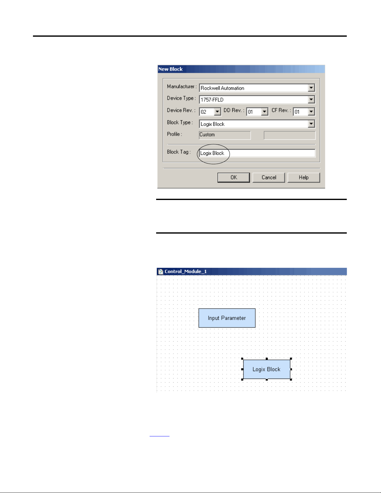
Create New Blocks in a Strategy Window
This option lets you create new blocks that do not already exist in the control
module.
IMPORTANT
1. With the Strategy window selected, click the template icon .
2. Click in the Strategy window area.
From the Tools menu, choose Tool Boxes>Strategy to open the Strategy
toolbar. Strategy should be checked. If not, check it.
e page 21
Se
for descriptions of the Strategy tools.
Rockwell Automation Publication 1757-UM012A-EN-P - July 2011 49
Page 50
Chapter 3 Create an RSFieldbus Software Project
IMPORTANT
The New Block dialog box appears.
The Device Rev, DD Rev and CF Rev values in this dialog box
default to the latest version in the device support files. If the
values do not match your firmware, change them or otherwise
you will receive a warning on download.
3. Enter a tag name for the block and click OK.
The new block appears in the Strategy window.
4. To remove an incorrect block, right-click the block and choose Delete.
Import a Template
See page 61 for procedures.
50 Rockwell Automation Publication 1757-UM012A-EN-P - July 2011
Page 51
Create an RSFieldbus Software Project Chapter 3
TIP
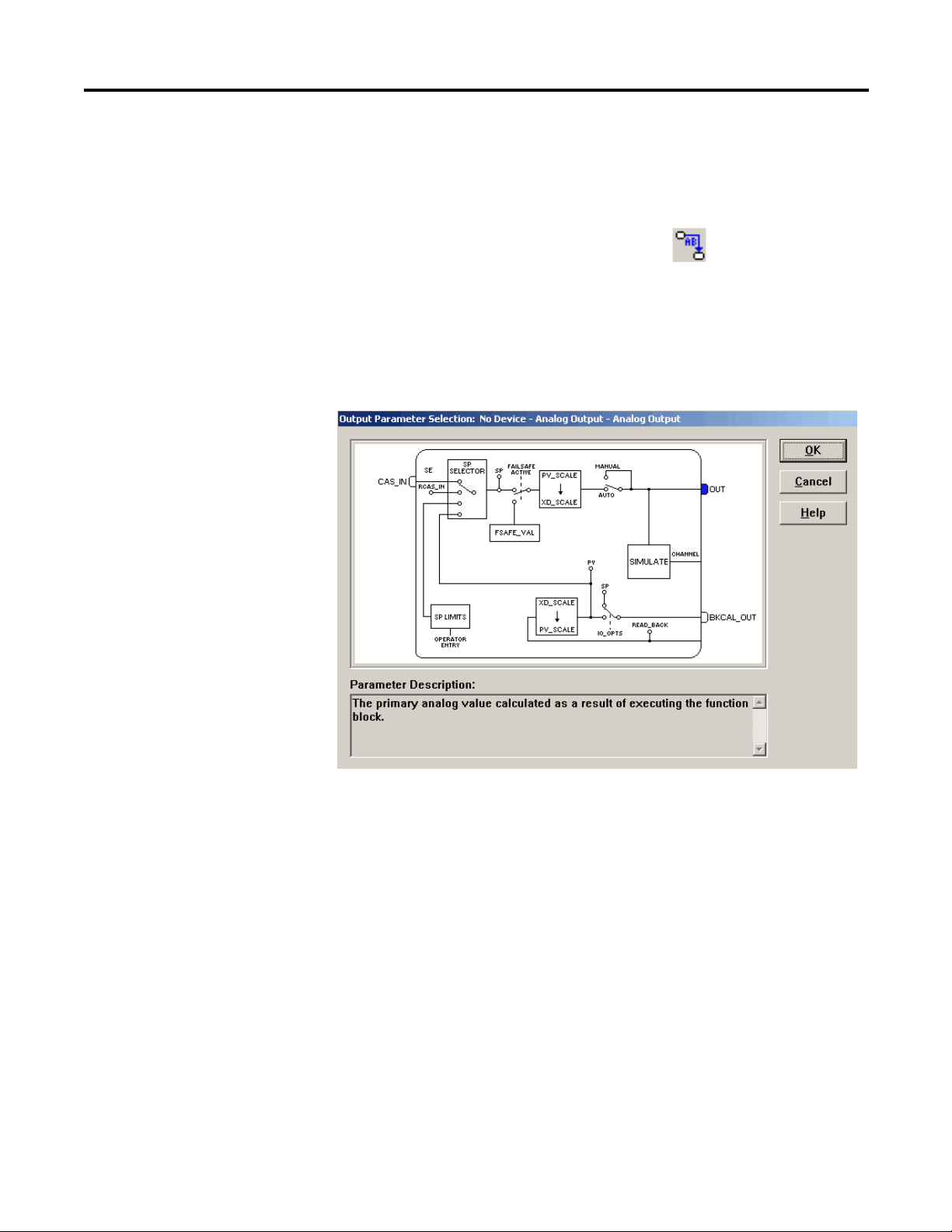
Link Blocks
You can link function blocks only in the Strategy window. Do these steps.
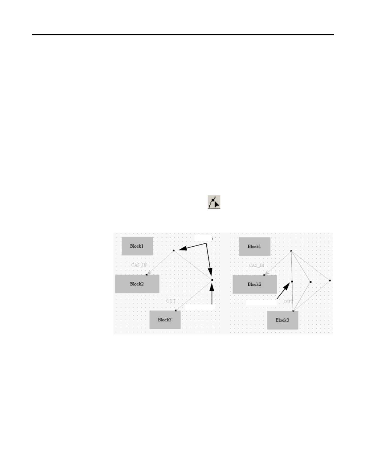
1. In the Strategy window, click the Link icon .
2. Click the first block.
The Output Parameter Selection dialog box appears.
You can mouse over the pins to read their descriptions at the bottom of the
dialog box.
3. Select a parameter, such as the OUT pin (as shown in the example).
The pin fills to show that it is selected.
4. Click OK.
A blue line is added to the block to represent the incomplete link.
5. Click the second block.
6. Select a parameter and click OK.
Press Shift to draw lines at 45° and 135°.
Press Control to draw lines at 0° and 90°.
Rockwell Automation Publication 1757-UM012A-EN-P - July 2011 51
Page 52
Chapter 3 Create an RSFieldbus Software Project
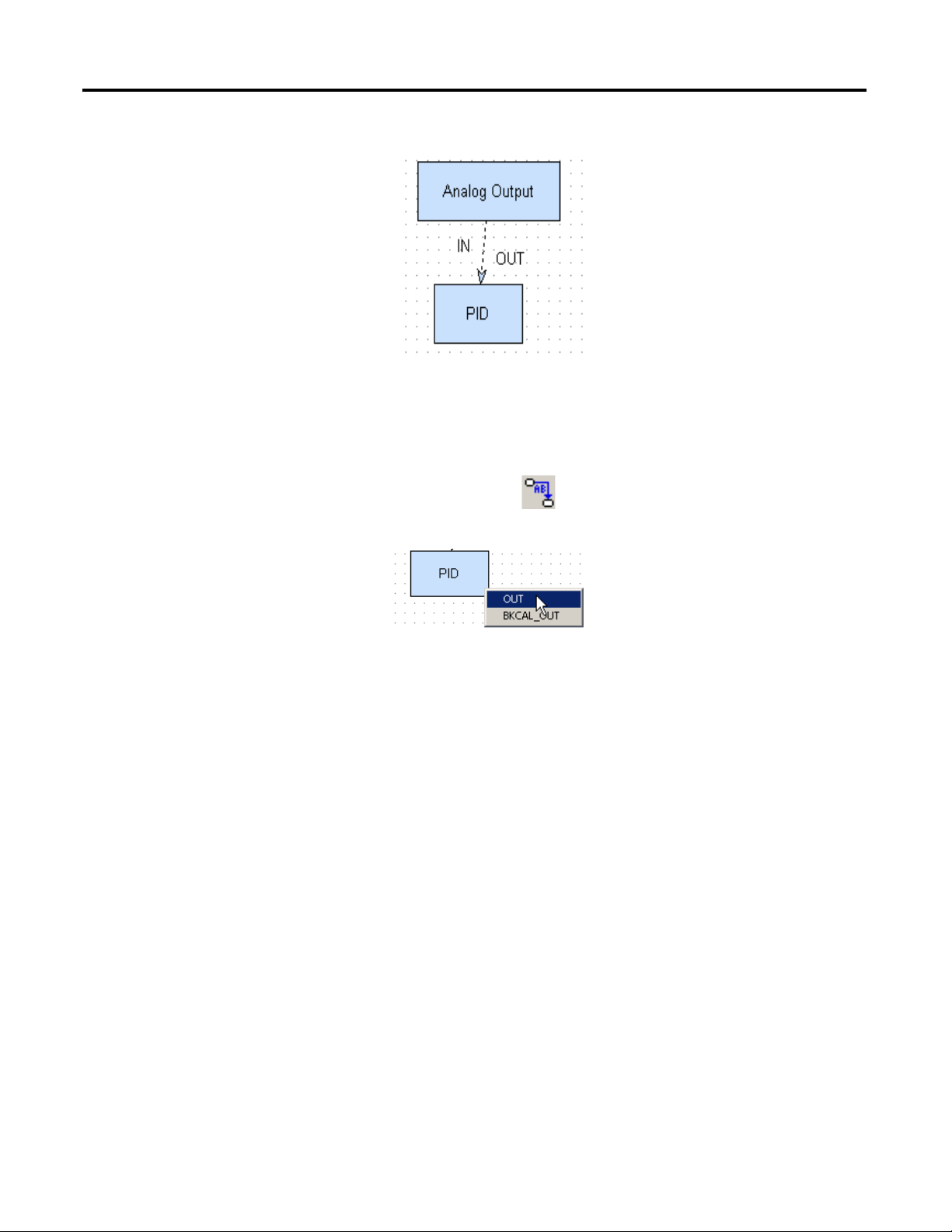
A link is drawn from the first block to the second block.
Fast Link
Do these steps to create links without opening the Parameter Selection window.
1. Click the Link icon .
2. Right-click the first block and choose the desired parameter.
3. Right-click the second block and choose the desired parameter.
The link is drawn.
52 Rockwell Automation Publication 1757-UM012A-EN-P - July 2011
Page 53

Create an RSFieldbus Software Project Chapter 3
Edit Link Attributes
This section describes how to change the attributes of links.
1. To change a link attribute, right-click selected links .
2. Use the block pop-up menu to make modifications as described in Ta b l e 2
Table 2 - Link Attributes
Menu Item Sub-menu item Action
Delete N/A Removes the link
Labels Show Link Label Displays the link label
Show Output Parameter Displays the output parameter
Show Input Parameter Displays the input parameter
Reference Point Ref. on Current Point Selected handle
Ref. on Previous Point Selected handle
the previous handle
Ref. on Next Point Selected handle
the next handle
Properties N/A Changes position, size, line, fill and text attributes
(1)
is the reference point
(1)
is placed based on the position of
(1)
is placed based on the position of
.
(1) See handle examples on page 54.
Delete and Restore Links
Do these steps to delete and restore function block links.
1. To delete a link, use the Select tool and click the link in the Strategy
window.
2. Right-click the link and choose Delete.
A pop-up dialog box appears with a message.
Rockwell Automation Publication 1757-UM012A-EN-P - July 2011 53
Page 54
Chapter 3 Create an RSFieldbus Software Project
Initial Position
Handles
Final Position
TIP
3. Do one of the following:
– To re m o ve th e l in k f ro m t he entire project, click Yes.
This action will also remove the block from the Process Cell window.
– To remove the link from the strategy only, click No.
This action hides the link. You can restore it, if necessary.
– To halt the deletion, click Cancel.
4. To restore links that have been deleted, right-click the block to which the
link was attached and choose Show Hidden Links.
Edit Line Links
Do these steps to change the way a link line is drawn.
1. Select the link.
2. Click the Modify icon .
3. Click a handle, or create a new one by clicking anywhere on the line, and
dragging it to the desired location.
Press Shift to draw lines at 45° and 135°.
Press Control to draw lines at 0° and 90°.
54 Rockwell Automation Publication 1757-UM012A-EN-P - July 2011
Page 55
Create an RSFieldbus Software Project Chapter 3
Use Tools for Function
Block Characterization
You have tools that provide access to the value and status of a block parameter as
well as let you make configurations both offline and online. You must save the
configuration upon closing, especially when online. If you ignore the prompt
warning to save, and do not save the changes, the configuration file will not have
the same values as the changes made in the device.
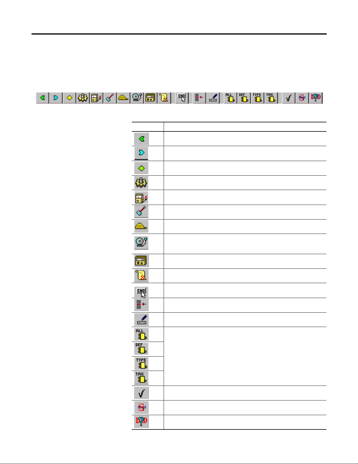
Table 3 - Function Block Characterization Toolbar
Toolbar Icon Description
Displays input parameters. An input parameter obtains its value from a source
external to the block.
Displays output parameters. An output parameter may be linked to an Input
Parameter of another block.
Displays contained parameters. A contained parameter is a parameter whose value
is configured, calculated, or set by an operator or higher level device.
Displays dynamic parameters. Dynamic parameters values are calculated by the
block algorithm and therefore do not need to be restored after a power failure.
Displays diagnostic parameters.
Displays service parameters.
Displays operating parameters.
Displays alarm parameters. Alarms and events (alerts) represent state changes
within block applications.
Displays tune parameters.
Displays the local parameters.
If this icon is pressed, you must click End Edit to complete an edit in this dialog box.
If it is not pressed, you can click another line in the dialog box to complete the edit.
Displays the Relative Index column.
Displays the Handling column, which shows read/write permission.
Displays the parameters for the block filter by the user customization.
Use this icon only in the online dialog box to save changes made in
online mode.
Toggles the Value display between a symbol and a numeric value.
Displays help information from the DD at the bottom of the Characterization
dialog box.
Rockwell Automation Publication 1757-UM012A-EN-P - July 2011 55
Page 56
Chapter 3 Create an RSFieldbus Software Project
Offline Characterization
This section explains how to configure function block parameters offline.
Do these steps.
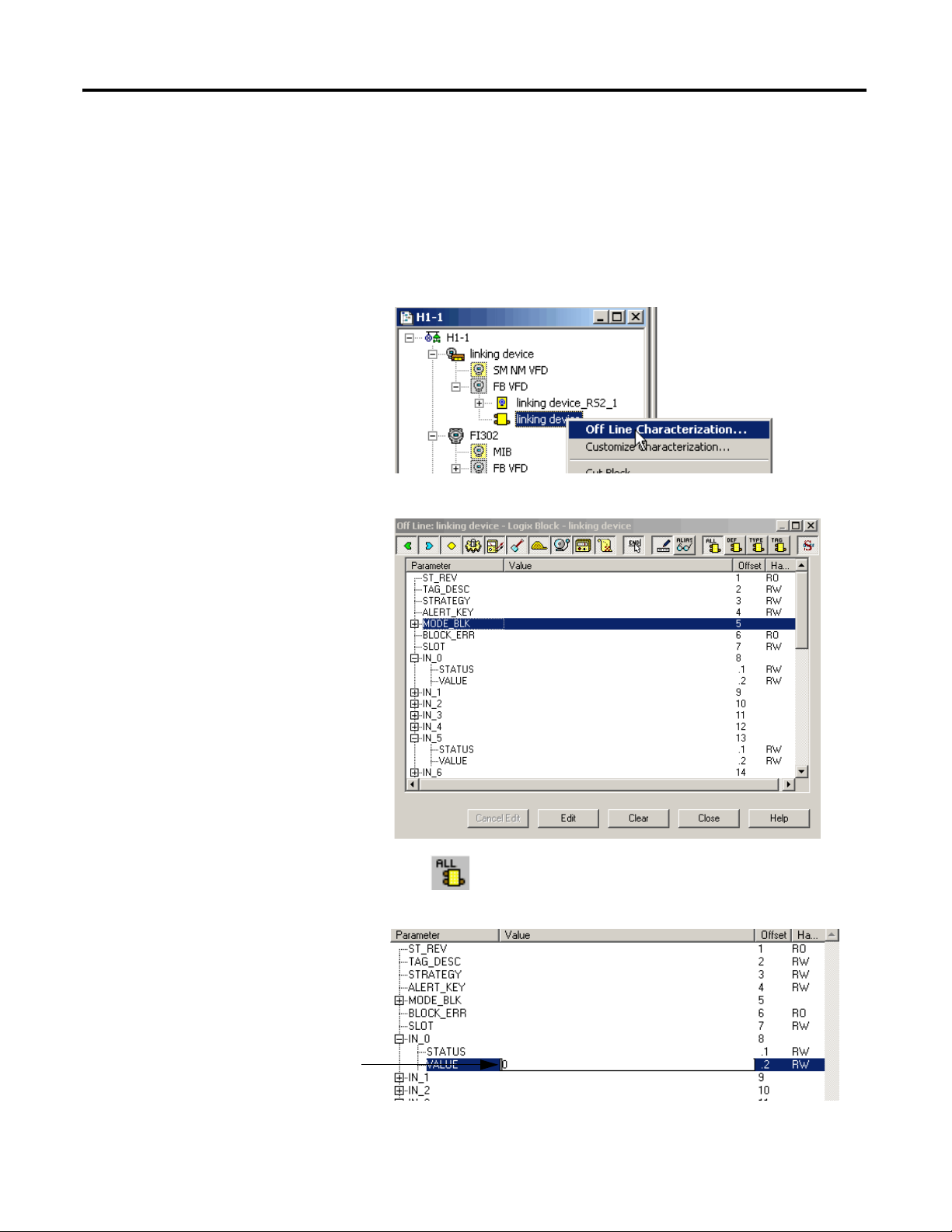
1. In the Fieldbus (H1) window, right-click the desired block and choose
Off Line Characterization.
The Off Line Characterization dialog box appears.
2. Click to view all parameters.
3. Select a desired parameter and click Edit at the bottom of the dialog box.
4. Enter a value and click End Edit.
56 Rockwell Automation Publication 1757-UM012A-EN-P - July 2011
Page 57

Create an RSFieldbus Software Project Chapter 3
5. Repeat step 3and step 4 for all desired parameters.
6. Click Close.
The edited parameters are added to the block.
Online Characterization
Once your project is online, you can edit the device parameters. Changes are
saved to the device, but you must save the project upon closing for the
configuration file to contain the same modifications.
1. In the Fieldbus (H1) window, right-click the desired block and choose
On Line Characterization.
The On Line Characterization dialog box appears.
2. Click to view all parameters.
3. Select a desired parameter and click Edit at the bottom of the dialog box.
4. Enter a value and click End Edit.
5. Repeat step 3
6. Click Close.
The edited parameters are added to the block.
and step 4 for all desired parameters.
Delete a Parameter
To delete a parameter once it has been configured in the Characterization dialog
box, right-click the corresponding icon in the Fieldbus (H1) or Process Cell
window and choose Delete Parameter.
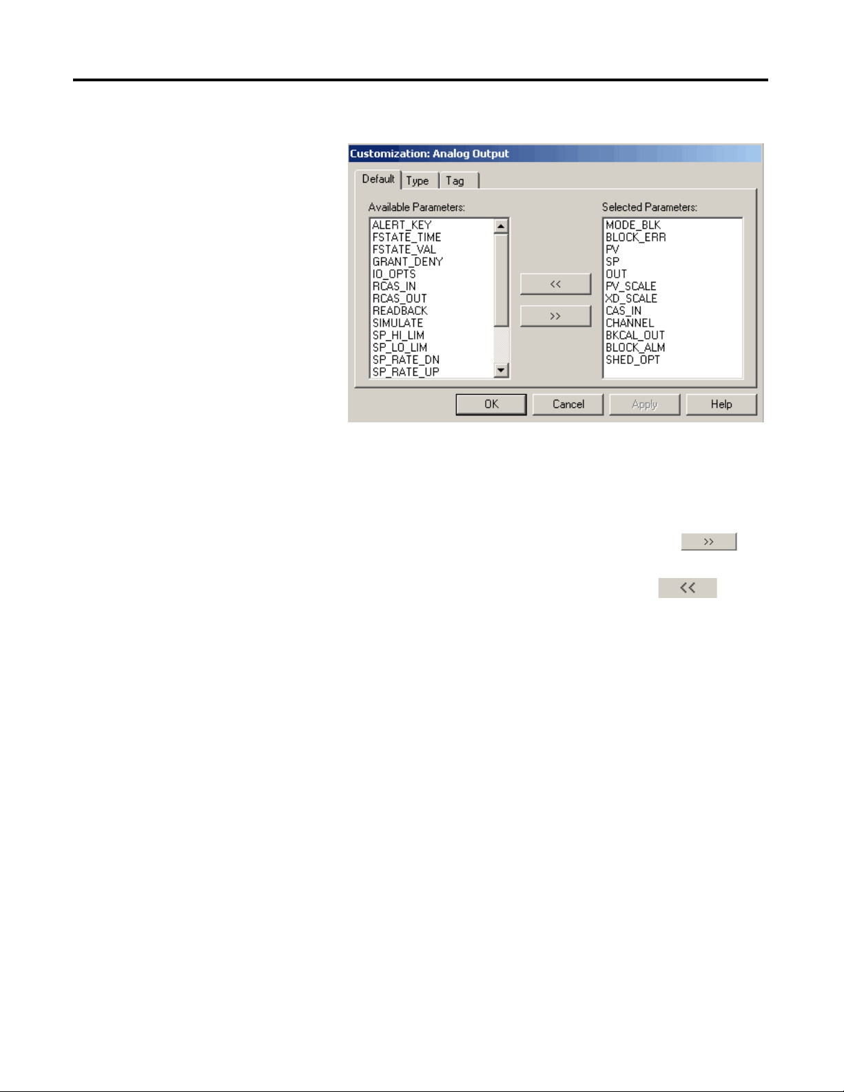
Customize Characterization Parameters
This option lets you customize specific function blocks with parameters listed in
the Characterization dialog box. Do these steps.
1. In the Fieldbus (H1) pr Process Cell window, right-click the desired block
and choose Customize Characterization.
Rockwell Automation Publication 1757-UM012A-EN-P - July 2011 57
Page 58
Chapter 3 Create an RSFieldbus Software Project
TIP
The Customization dialog box appears.
2. Do one of the following to move available parameters to selected
parameters and vice versa:
Procedures are the same for the three tabs—Default, Type, Tag.
– Select an ‘Available’ parameter and click the right arrow to
move the parameter to the ‘Selected’ parameter box.
– Select a ‘Selected’ parameter and click the left arrow to move
the parameter to the ‘Available’ parameter box.
3. Click Apply.
4. Click OK.
58 Rockwell Automation Publication 1757-UM012A-EN-P - July 2011
Page 59
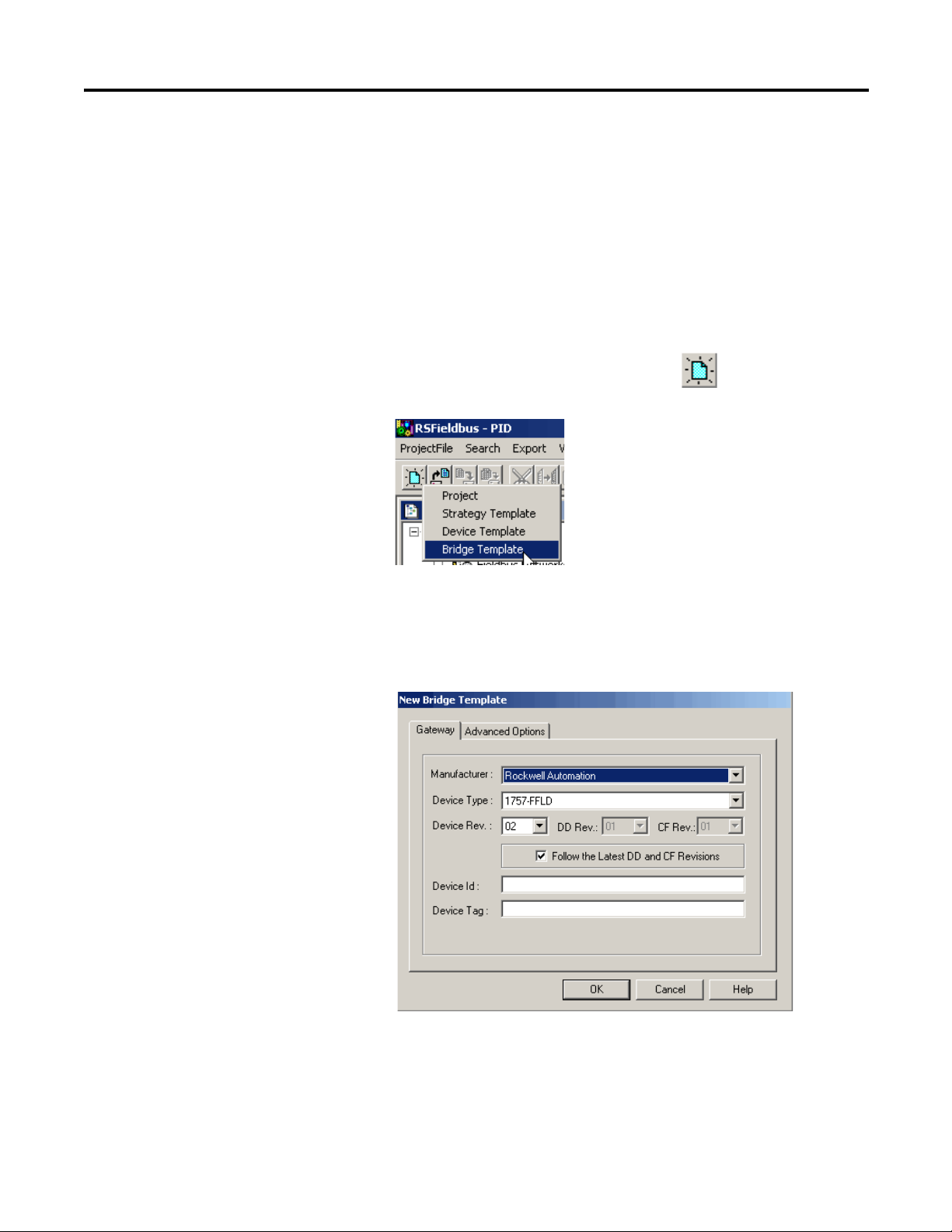
Create an RSFieldbus Software Project Chapter 3
TIP
Design Templates
Templates save time and provide consistency to your projects. This section
describes how to create a base template and how to import and export the
template into projects.
Create a Device or Bridge Template
Do these steps to create a device or bridge template. This base template can be
used for the same block type for other projects.
1. From the RSFieldbus main menu, click New and choose
Bridge Template.
You also can choose Device Template from the New pull-down
menu. For our example, we will create a bridge template.
Procedures are the same for creating a device template.
The New Bridge Template dialog box appears.
2. Choose the Manufacturer, Device Type, and Device Rev.
3. Enter a device tag name.
Rockwell Automation Publication 1757-UM012A-EN-P - July 2011 59
Page 60

Chapter 3 Create an RSFieldbus Software Project
IMPORTANT
4. Click the Advanced Options tab.
5. Make desired selections and click OK.
6. From the RSFieldbus main menu, choose Save As on the ProjectFile menu.
The Save As dialog box appears.
7. Choose a folder in which to save the template.
We recommend that you save all templates in the RSFieldbus
software templates folder. Choose Program Files> Rockwell
Software> RSFieldbus> Fieldbus Manager>Templates.
8. Enter a name for the template and click OK.
9. To save this base as the default template, from the ProjectFile menu, choose
Save as Default Template.
This template will be used as the base of each device or bridge of that type
that you add to your projects.
Edit the Default Template
Do these steps to modify the default base template.
1. From the ProjectFile menu, choose Open Default Template.
The Open Default Template dialog box appears.
2. Choose the Manufacturer, Device Type, and Device Rev.
3. Click OK.
4. Make changes to the template.
5. From the ProjectFile menu, choose Save as Default Template.
6. Close the template.
60 Rockwell Automation Publication 1757-UM012A-EN-P - July 2011
Page 61

Create an RSFieldbus Software Project Chapter 3
Import a Template into a Project
Do these steps to use a template to create a bridge or device for a project.
1. Right-click the HSE Network icon and choose New>Bridge
from Template.
The Open dialog box appears.
2. Browse to the location of your templates.
3. Select the desired template and click Open.
A message dialog box appears to confirm the importing of the template.
4. Click OK.
Rockwell Automation Publication 1757-UM012A-EN-P - July 2011 61
Page 62
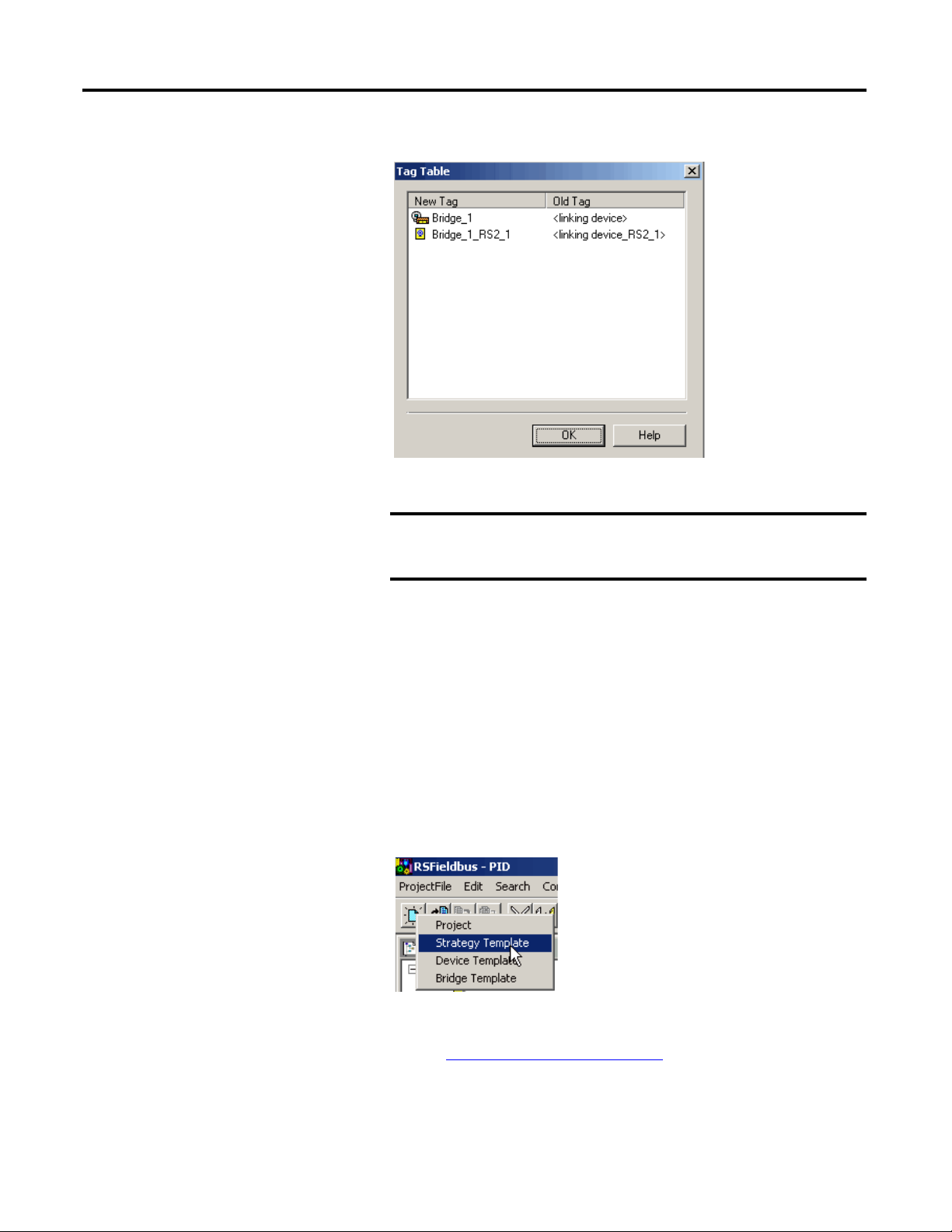
Chapter 3 Create an RSFieldbus Software Project
IMPORTANT
Th e Ta g Tab le ap pea rs .
5. Right-click a tag in the New Tag column to rename the tag name.
Make sure your tag names are different in your RSFieldbus
projects on the same HSE server or your project may not
function properly.
6. Click OK.
The bridge or device is added to your project.
Create and Import a Strategy Template
Do these steps to create a template that you can use to import and export a
strategy into projects.
1. From the RSFieldbus main menu, click New and choose
Strategy Template.
The Template dialog box appears.
2. Refer to Create a New Strategy on page 48
a strategy.
for initiating and saving
62 Rockwell Automation Publication 1757-UM012A-EN-P - July 2011
Page 63

Create an RSFieldbus Software Project Chapter 3
IMPORTANT
3. Open a Strategy window and from the Tools menu, choose Strategy,
Import Strategy Template.
The Open dialog box appears.
4. Browse to the location of your templates.
5. Select the desired template and click Open.
The template and the Importing Template window appear.
Use the HSE Network Setup
Tool
Add Device to the FFLDC
ControlNet Setup Tool
See Appendix F for details on how to use the HSE Network Setup Tool to
activate multiple network cards or an inactive1757-FFLD linking device.
Do these steps to define the CIP path of the 1757-FFLDC linking device to the
IDShell HSE.ini file so the RSFieldbus software can communicate with various
linking devices connected through the ControlNet network.
6. Click OK.
The template is added to the strategy.
7. Attach the added blocks to their respective devices.
8. Save your work.
• RSLinx Classic software must be installed to use the FFLDC
ControlNet Setup Tool.
• The linking device’s EDS file must be installed to use the
FFLDC ControlNet Setup Tool.
1. Configure the proper RSLinx Classic drivers to navigate to the
ControlNet network where your 1757-FFLDC linking device resides.
2. Choose Start>Programs>Rockwell Software>RSFieldbus>
FFLDC ControlNet Setup.
Rockwell Automation Publication 1757-UM012A-EN-P - July 2011 63
Page 64
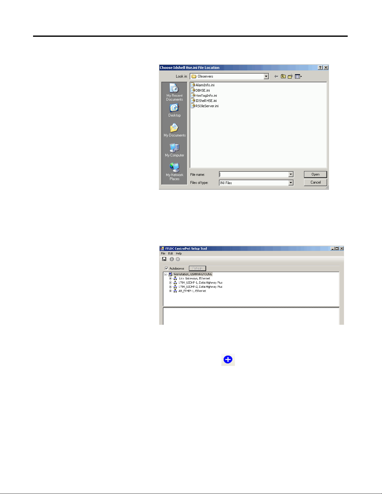
Chapter 3 Create an RSFieldbus Software Project
The Open dialog box appears to the default installation folder.
If RSFieldbus software was not installed to the default folder, you must
browse to the folder where it was installed.
3. Double-click the IDShell HSE.ini file.
The FFLDC ControlNet Setup Tool appears.
4. Browse the network and select the 1757-FFLDC linking device that you
plan to use in your RSFieldbus projects.
5. Click the Add Item icon .
64 Rockwell Automation Publication 1757-UM012A-EN-P - July 2011
Page 65

Create an RSFieldbus Software Project Chapter 3
The FFLDC path is added to the lower window.
6. Complete step 4
and step 5 with all other 1757-FFLDC linking devices
you plan to use in RSFieldbus projects.
7. Click the Save to INI file icon .
The CIP path is saved to the IDShell HSE.ini file.
8. Close the FFLDC ControlNet Setup tool.
Rockwell Automation Publication 1757-UM012A-EN-P - July 2011 65
Page 66

Chapter 3 Create an RSFieldbus Software Project
Notes:
66 Rockwell Automation Publication 1757-UM012A-EN-P - July 2011
Page 67
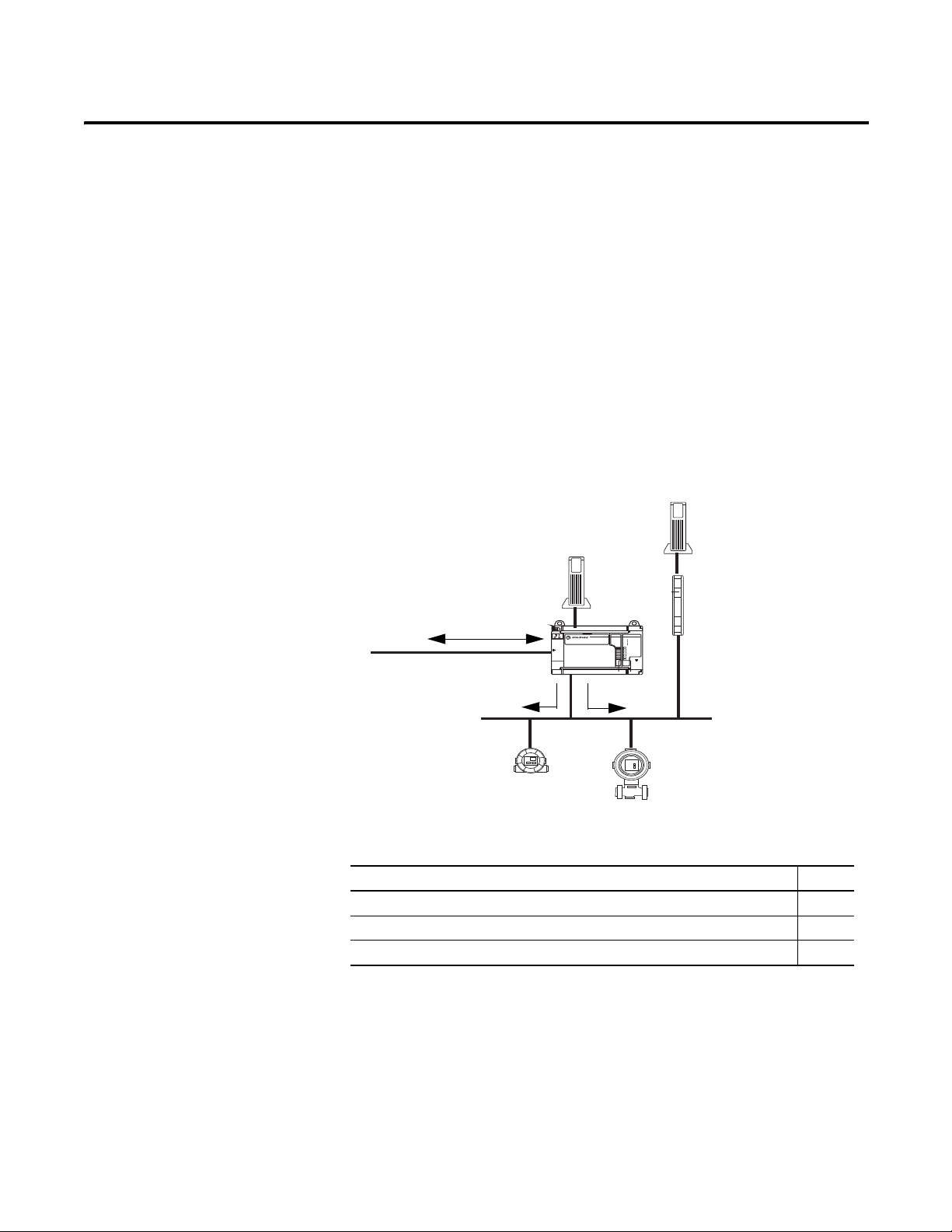
RSFieldbus Communication
STATUS
WD0G
BATT
NS
MODE
H1-1
H1-2
H1-3
H1-4
FOUNDATION Fieldbus
FOUNDATION Fieldbus
Linking Device
A
B
H-1
Ethernet network to
Logix controller and
RSFieldbus workstation.
1757-FFLD
Power Supply
Power Conditioner
Field Devices
45584
H-1
Chapter
4
Introduction
This section describes how to set up an RSFieldbus project to communicate with
field devices. A project must be created and a bridge module (linking device)
must be in the configuration.
The linking device, such as the 1757-FFLD shown in Figure 6, provides
connectivity for fieldbus devices to Logix controllers via H1 networks.
Figure 6 - Linking Device Connectivity Example
Rockwell Automation Publication 1757-UM012A-EN-P - July 2011 67
The table lists the main topics described in this section.
Topic Page
Initialize Communication 68
Assign Tags 71
Download the Configuration 74
Page 68
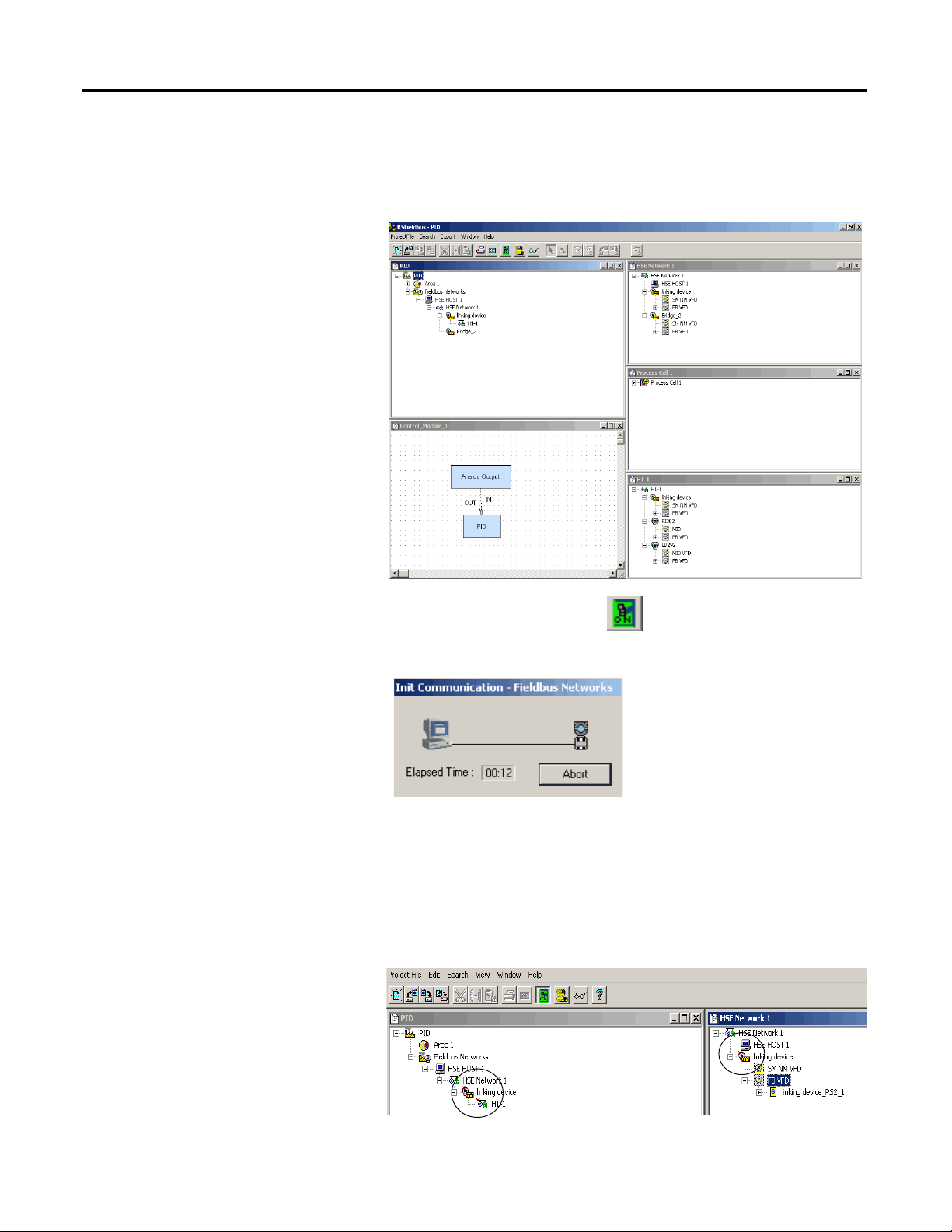
Chapter 4 RSFieldbus Communication
TIP
Initialize Communication
Do these steps to start the communication process with field devices.
1. From the Window menu, choose Tile to make all windows visible at the
same time.
2. Click the RSFieldbus online icon .
The Initialize Communication animation begins.
During this time, all devices are located on the network.
This window may appear for up to 20 seconds while RSFieldbus
software is waiting for the HSE Server to respond.
A red ‘x’ appears next to the H1, linking device, and device icons. This
indicates that they need to be associated with the actual hardware.
68 Rockwell Automation Publication 1757-UM012A-EN-P - July 2011
Page 69
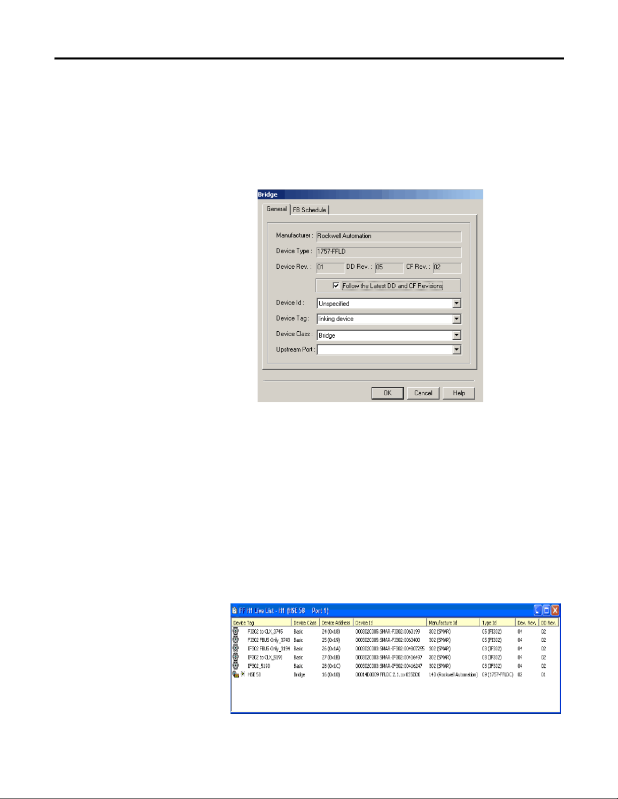
RSFieldbus Communication Chapter 4
There is an order of precedence in associating devices. The bridges on the
HSE network need to be associated prior to the devices on the H1
network, because the linking device is the link between the H1 and the
host computer.
3. Right-click the linking device and choose Attributes.
The Bridge dialog box appears.
4. From the Device Id pull-down menu, choose the corresponding device ID.
5. Click OK.
Note that the red ‘x’ in the HSE window has disappeared once the
association is made. This indicates that communication with the linking
device is established.
The next step requires opening the Live List to verify that you are
connected to the proper devices.
6. Right-click H1-1 network and choose Live List.
The H1-1 Live List appears and shows all of the devices connected
through your linking device.
Rockwell Automation Publication 1757-UM012A-EN-P - July 2011 69
Page 70
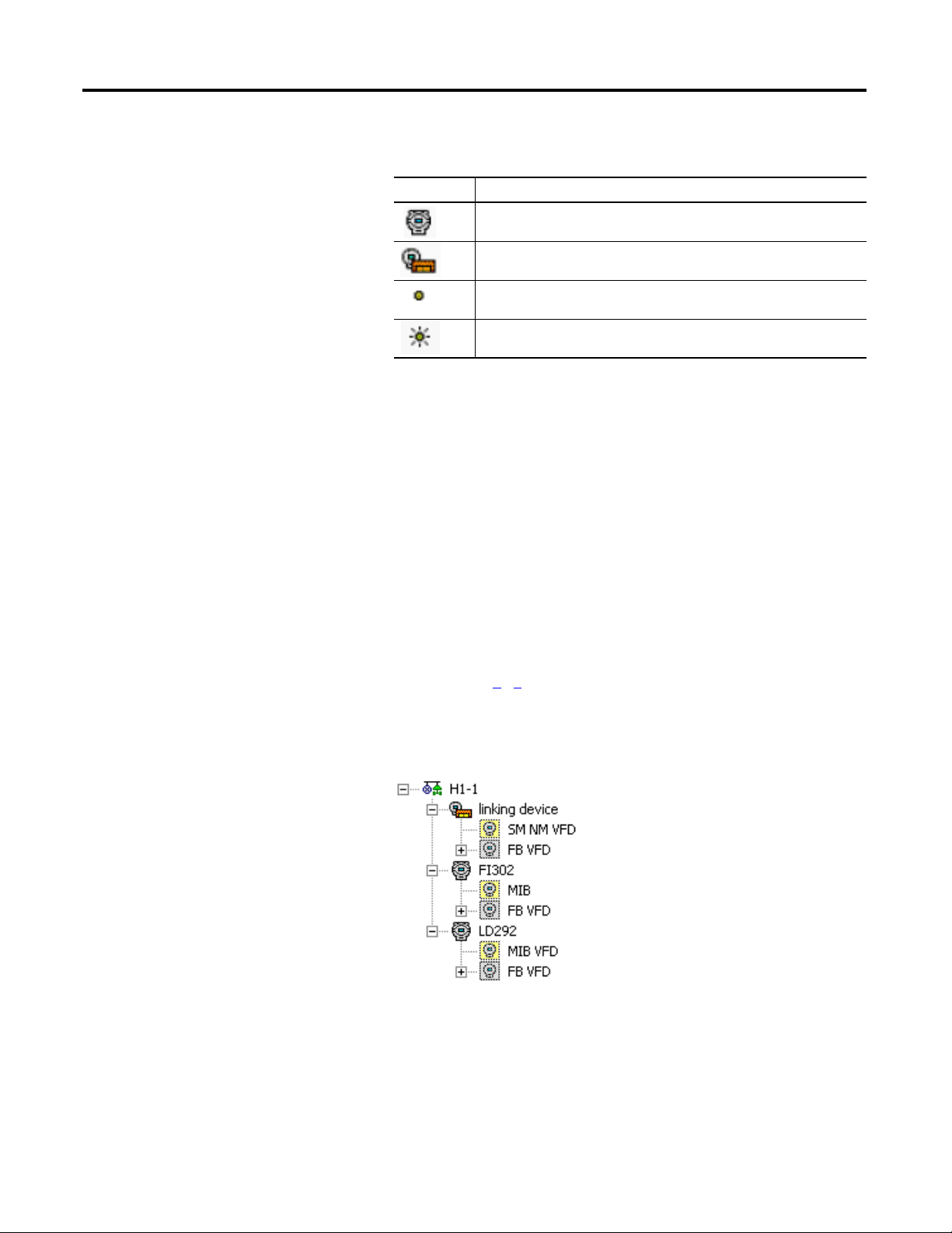
Chapter 4 RSFieldbus Communication
The table describes the symbols used in the Live List.
Symbol Description
Basic device
Bridge
Link master
Link active scheduler
Devices that are ghosted (dimmed) in the H1-1 Live List have not yet
established a connection to RSFieldbus through the HSE Server and
linking device. Prior to continuation, the device must not be in a ghosted
state in the live list.
Associate Devices
If this is the first time you have initialized communication, you must assign the
Device Ids.
1. In the Project window, right-click the device and choose Attributes.
2. Choose the corresponding Device Id from the pull-down menu.
3. Click OK.
4. Complete steps 1
…3 for each device.
Note that the red ‘x’ next to each device in the HSE window has
disappeared once the association is made. This indicates that
communication with the linking device is established.
70 Rockwell Automation Publication 1757-UM012A-EN-P - July 2011
Page 71
RSFieldbus Communication Chapter 4
IMPORTANT
TIP
Assign Tags
This section describes how to assign unique tags to each device to differentiate
between similar devices on the network.
ATTENTION: During this procedure, control of the associated devices
and anything linked to them will be lost.
If this procedure is not done, the device tag in the project and the online
device tag will not match and the project cannot be downloaded.
1. In the H1 window, right-click the linking device and choose Attributes.
The Bridge dialog box appears.
You must give each tag its own unique name so a tag cannot be
duplicated in the same project.
2. Type a device tag name.
ATTENTION: Be sure the tags used in your RSFieldbus projects on
the same HSE Server are unique or your project may not function
properly.
Tags cannot include a ’.’ (period). If a separator is needed, use an
’_’ (underscore). Spaces are allowed, but not recommended.
3. Click OK.
4. Right-click the linking device icon and choose Assign Tags.
5. Click OK when you are asked if you want to assign a new tag.
The Assign Tag dialog box appears and the tag is sent to the device.
6. Repeat step 1
through step 5 in the H1 window for all devices in
the project.
7. You also can assign tags to all the devices at one time rather than
individually by right-clicking HSE Network and choosing Assign All Tags.
Rockwell Automation Publication 1757-UM012A-EN-P - July 2011 71
Page 72
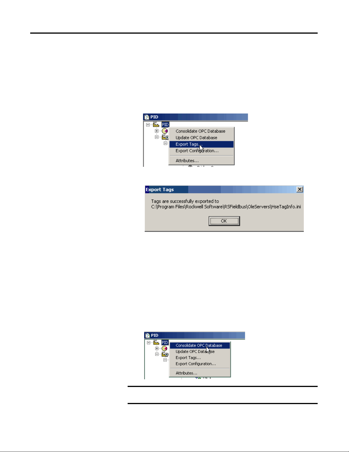
Chapter 4 RSFieldbus Communication
IMPORTANT
Export Tags
A file with all the device and function block tags must be created to enable online
OPC communication with RSFieldbus software and third-party OPC clients.
Each time that you edit or add a device or block, the Export Tags procedure must
be repeated. Otherwise, supervision of the modified tag is not allowed.
1. In the Project window, right-click a project icon and choose Export Tags.
The Export Tag message window appears.
2. Click OK.
Consolidate the OPC Database
If your system has a centralized OPC server and you are using multiple projects at
the same time, you must consolidate the project tags for each project. This
process prevents exported tag information in the HseTagInfo.ini file from being
overwritten when tags are exported in the next project.
1. In the Project window, right-click a project icon and choose Consolidate
OPC Database.
Tags must be exported from at least one project before you can open the
Consolidate OPC Database dialog box.
72 Rockwell Automation Publication 1757-UM012A-EN-P - July 2011
Page 73

RSFieldbus Communication Chapter 4
IMPORTANT
The Consolidate OPC Database dialog box appears.
This dialog box lets you do the following:
• Add a project, see page 73
• Remove a project, see page 74
• Clear the project list, see page 74
.
.
.
Add a Consolidated Project
Do these steps to add a project to the consolidated list.
Only the project that is currently open can be added to the
consolidate list.
1. To add the project that is currently open, click Add This on the
Consolidate OPC Database dialog box.
A message dialog box appears to confirm that you are adding this project.
2. Click Yes.
When Yes, the following configuration occurs:
– Project name is added to the list of configurations and the
HseTagInfo_CONSOLIDATION.ini file is created in the OLE Server
folder.
– The TagInfo.ini and HseTagInfo_CONSOLIDATION.ini files are
updated when you export tags.
If you need to change a tag in a project that already has been added to the
consolidated list, you must update the tag list. The Update This button
replaces Add This on the Consolidate OPC Database dialog box to let you
update the tag.
Rockwell Automation Publication 1757-UM012A-EN-P - July 2011 73
Page 74

Chapter 4 RSFieldbus Communication
Remove a Consolidated Project
Do these steps to remove a project from the consolidated list.
1. In the Consolidate OPC Database dialog box, select a project in the
Configurations section.
2. Click Remove.
A message dialog box appears to confirm you want to remove the project.
3. Click Yes.
A message dialog box appears to confirm the project has been removed.
The tags are removed from the HseTagInfo_CONSOLIDATION.ini file.
4. Click OK.
Clear the Consolidated List
Download the
Configuration
Do these steps to clear the list of consolidated projects and remove all the tag lists
from the OPC server.
1. Open the Consolidated OPC Database dialog box.
Projects are listed in the Configurations section of the dialog box.
2. Click Clear All.
A message dialog box appears to confirm you are clearing the projects.
3. Click Yes.
Before downloading a project, you must complete the Export Tags function. This
lets you view function block parameters online.
See page 72
You also should clear the error log so new errors will be easier to detect.
1. Click the Error Log icon .
for procedures.
2. Right-click within the Communication dialog box, and choose Clear Log.
The dialog box clears.
3. In the HSE Fieldbus dialog box, right-click the HSE icon and
choose Download.
74 Rockwell Automation Publication 1757-UM012A-EN-P - July 2011
Page 75
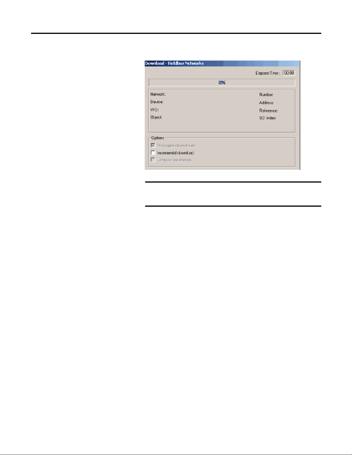
The Download dialog box appears.
IMPORTANT
The Propagate downstream is checked and dimmed by default.
This means that after the HSE is downloaded, all H1 segments in
the project are then downloaded.
RSFieldbus Communication Chapter 4
4. Click Start.
The Download dialog box shows the progress while the
configuration downloads.
After a download, it may take up to two minutes for OPC data to be
available from the OPC server.
Rockwell Automation Publication 1757-UM012A-EN-P - July 2011 75
Page 76

Chapter 4 RSFieldbus Communication
Notes:
76 Rockwell Automation Publication 1757-UM012A-EN-P - July 2011
Page 77

Chapter
ControlLogix Controller with
the 1756-ENBT Module
Ethernet/IP
RSFieldbus
OPC
OPC Client
24V DC
Power
Supply
1757-FFLD
Linking Device
H1
Power
Conditioner
44428
Field
Devices
24V DC
Power
Supply
IMPORTANT
5
Create an RSLogix 5000 Software Project
Introduction
Ethernet - 1757-FFLD
Linking Device Example
This section describes how to set up a linking device with a Logix5000 controller
by using the RSLogix 5000 software. Examples show the 1757-FFLD linking
device but procedures are similar for the 1757-FFLDC linking device, which
bridges H1 field devices to Logix controllers via the ControlNet network.
Topic Page
Create a Project for the Controller 78
Add the Communication Module, Linking Device, and Logix
Blocks
Schedule the ControlNet Network 93
Electronic Keying 94
80
The 1757-FFLD linking device uses the Ethernet/IP network to connect to an
H1 segment so fieldbus devices can communicate with ControlLogix controllers.
Rockwell Automation does not support the 1757-FFLD and
1757-FFLDC linking devices communicating with the same
HSE server in the same RSFieldbus project.
In this illustration, the 1757-FFLD linking device does the following:
• Serves as a bridge between the EtherNet/IP and H1 networks.
• Provides connectivity for Foundation Fieldbus devices to
Rockwell Automation Publication 1757-UM012A-EN-P - July 2011 77
Logix controllers.
Page 78

Chapter 5 Create an RSLogix 5000 Software Project
Create a Project
for the Controller
This section shows how to use the RSLogix 5000 programming software to start
a project and configure a Logix5000 controller.
Do these steps to create a project.
1. Start the RSLogix 5000 software, and click the New icon .
The New Controller dialog box appears.
The example shows information for instructional purposes.
2. Configure the controller by entering information in the New Controller
dialog box.
Field Description Field Description
Vendor Defaults to Allen-Bradley. Description Type an optional
Type Choose the type of
Revision Defaults to the latest
Redundancy
Enabled
Name Type a name for the
controller from the pulldown menu.
revision of the
ControlLogix controller.
You cannot override this
field until you click OK.
Clear the checkbox if you
are not
using redundancy.
controller. See
Conventions for Names
for more information.
Chassis Type Choose a chassis type
Slot Use the Up/Down arrow
Create in Use the default project
description for the
controller.
from the pull-down menu.
to select the appropriate
slot number for the
controller in your chassis.
folder or click Browse to
select another database
location.
3. Click OK.
78 Rockwell Automation Publication 1757-UM012A-EN-P - July 2011
Page 79

Create an RSLogix 5000 Software Project Chapter 5
The RSLogix 5000 window redisplays with the controller project name in
the Controller Organizer.
Conventions for Names
Throughout a Logix5000 project, you define names for the different elements of
the project such as the controller, data addresses (tags), routines, I/O modules,
and so forth. As you enter names, follow these rules:
• Must start with a letter or an underscore
• Only letters, numbers, and underscores (_)
• ≤ 40 characters
• No consecutive or trailing underscores
• Not case sensitive
Rockwell Automation Publication 1757-UM012A-EN-P - July 2011 79
Page 80
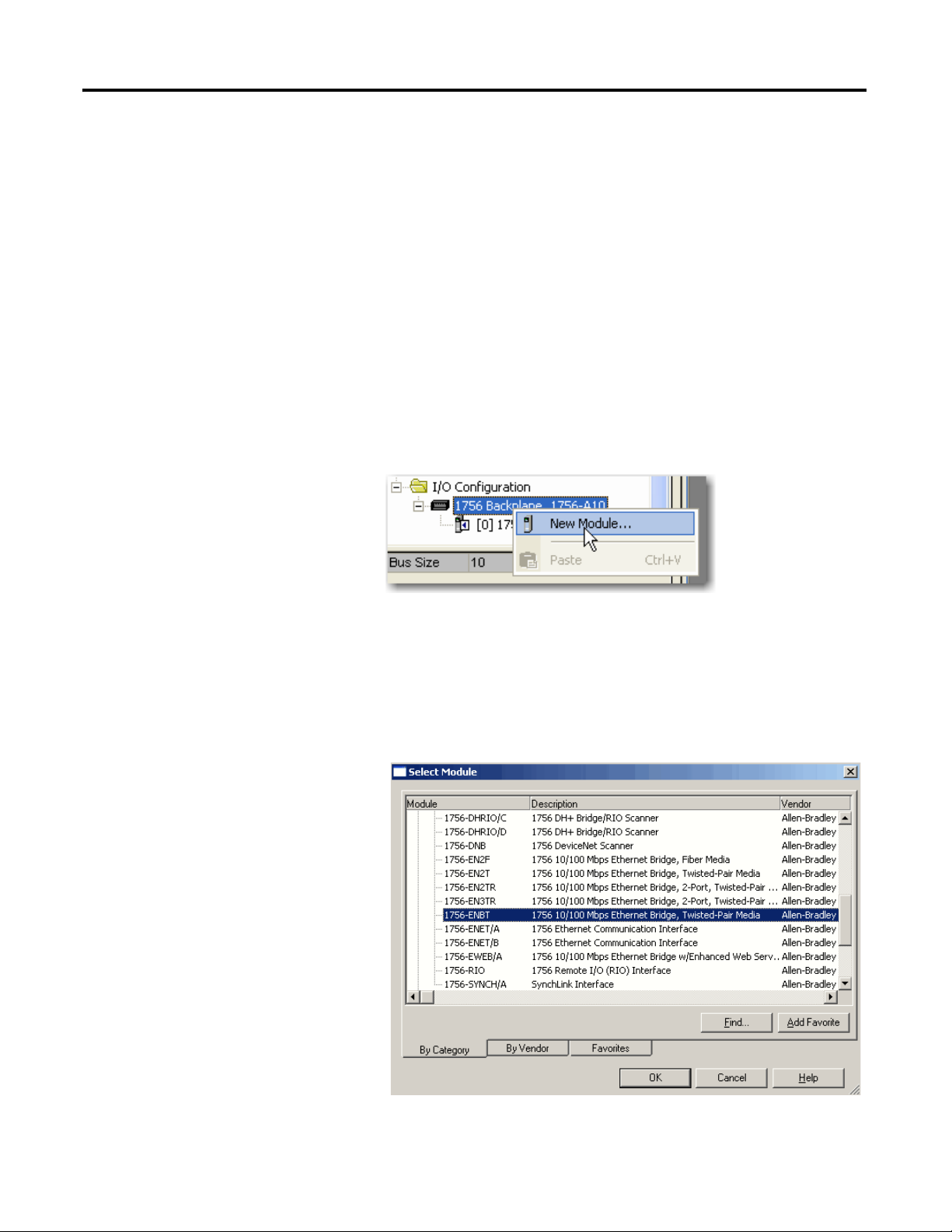
Chapter 5 Create an RSLogix 5000 Software Project
Add the Communication
Module, Linking Device,
and Logix Blocks
To communicate with the controller, you add a local communication module, the
linking device, and then the Logix Blocks. Within the I/O Configuration folder,
organize the modules into a hierarchy (tree/branch, parent/child).
Add the Communication Module
The communication bridge module establishes the EtherNet/IP address to allow
the linking device to communicate with the ControlLogix controller.
If configuring a 1757-FFLDC linking device, you add a ControlNet
communication module, such as a 1756-CNBR module.
Do these steps to create a communication module.
1. Right-click the 1756 Backplane and choose New Module.
The Select Module dialog box appears with a list of module types.
2. Click the ‘+’ sign in front of Communications.
A list of communication modules appears.
3. Select the appropriate communication bridge module, such as the
1756-ENBT module.
4. Click OK.
80 Rockwell Automation Publication 1757-UM012A-EN-P - July 2011
Page 81
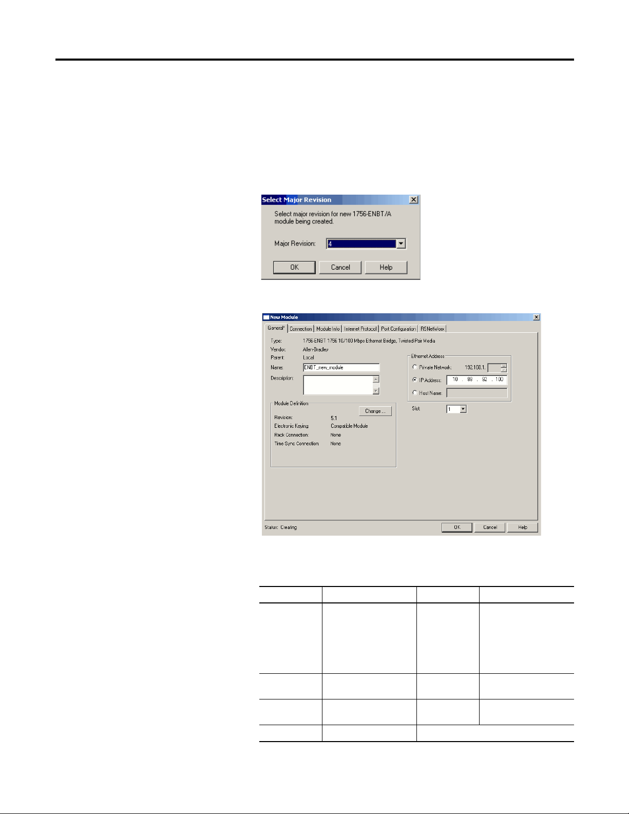
Create an RSLogix 5000 Software Project Chapter 5
TIP
The Select Major Revision pop-up dialog box appears.
The Major Revision number represents the functional capabilities and data
exchange formats of the module. Typically, although not always, a later, that is
higher, Major Revision supports at least all of the data formats supported by
an earlier, that is lower, Major Revision of the same catalog number and,
possibly, additional ones.
5. Choose the module revision and then click OK.
The New Module dialog box appears.
6. Configure the communication module by entering information in the
New Module dialog box.
Field Description Field Description
Type Field defaults the type of
module that you are
initiating.
Vendor Defaults to Allen-Bradley. Description Type a description
Parent Defaults to Local
(chassis).
Name Type a module name.
Rockwell Automation Publication 1757-UM012A-EN-P - July 2011 81
Ethernet
Address
Private Network
IP Address
Host Name
Slot Select a slot number for
Use the default of IP
Address and type the
Ethernet address.
(optional) for the module.
the module in the chassis.
Page 82

Chapter 5 Create an RSLogix 5000 Software Project
7. In the Module Definition box, click Change.
The Module Definition dialog box appears.
8. Complete the module definition dialog box.
Field Description
Revision Defaults both the Major Revision (first field)
and Minor Revision numbers. Choose the
appropriate revisions from the pull-down
menus, if necessary.
Electronic Keying Use the default of Compatible Module or
choose Exact Match or Disable Keying from
the pull-down menu.
See page 94 for details.
Rack Connection Choose the rack connection.
See the ControlLogix Analog I/O Modules
User Manual, publication 1756-UM009
for more information.
Time Sync Connection Choose the time synchronization connection.
See the ControlLogix Analog I/O Modules
User Manual, publication 1756-UM009
for more information.
9. Click OK.
,
,
82 Rockwell Automation Publication 1757-UM012A-EN-P - July 2011
Page 83
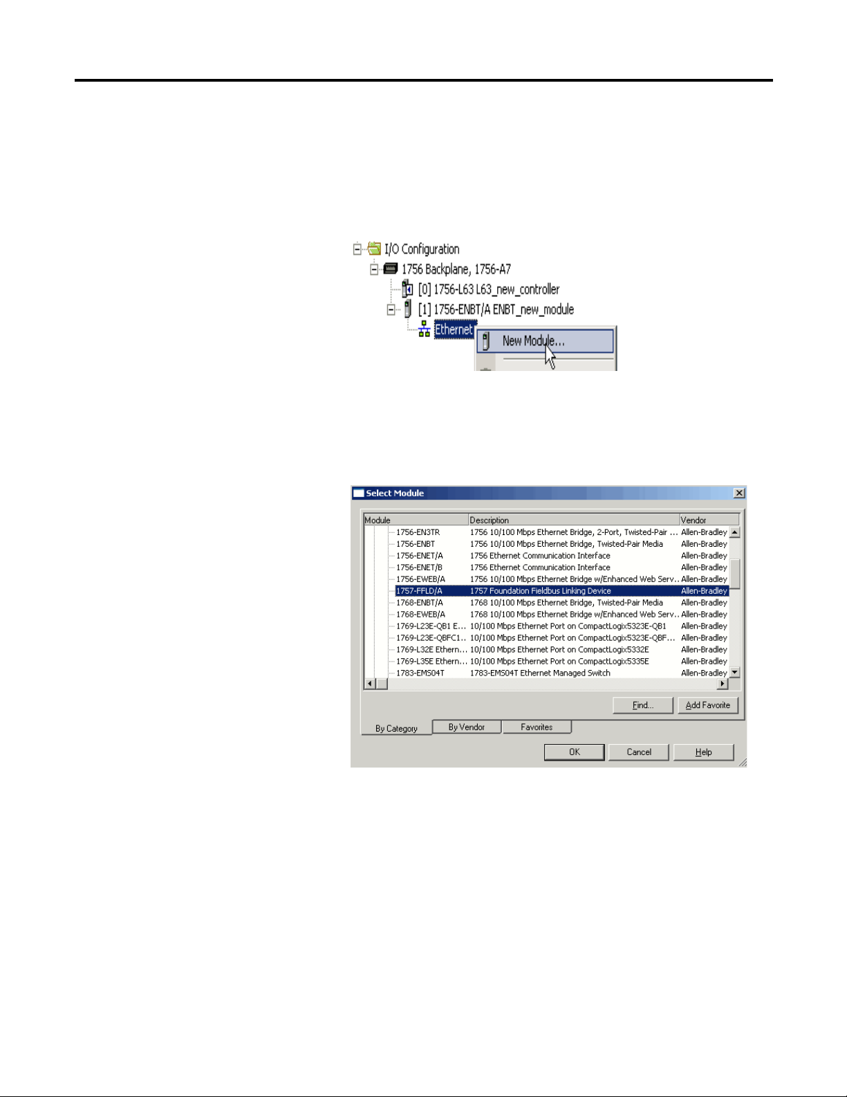
Create an RSLogix 5000 Software Project Chapter 5
Add the Linking Device
Do these steps to add a linking device to communicate to field devices.
1. In the Controller Organizer, right-click Ethernet and choose
New Module.
The Select Module window dialog box appears.
2. Click the ‘+’ sign in front of Communications on the Select Module
dialog box.
3. Select the 1757-FFLD Linking Device.
4. Click OK.
5. Choose a module revision and click OK.
Rockwell Automation Publication 1757-UM012A-EN-P - July 2011 83
Page 84
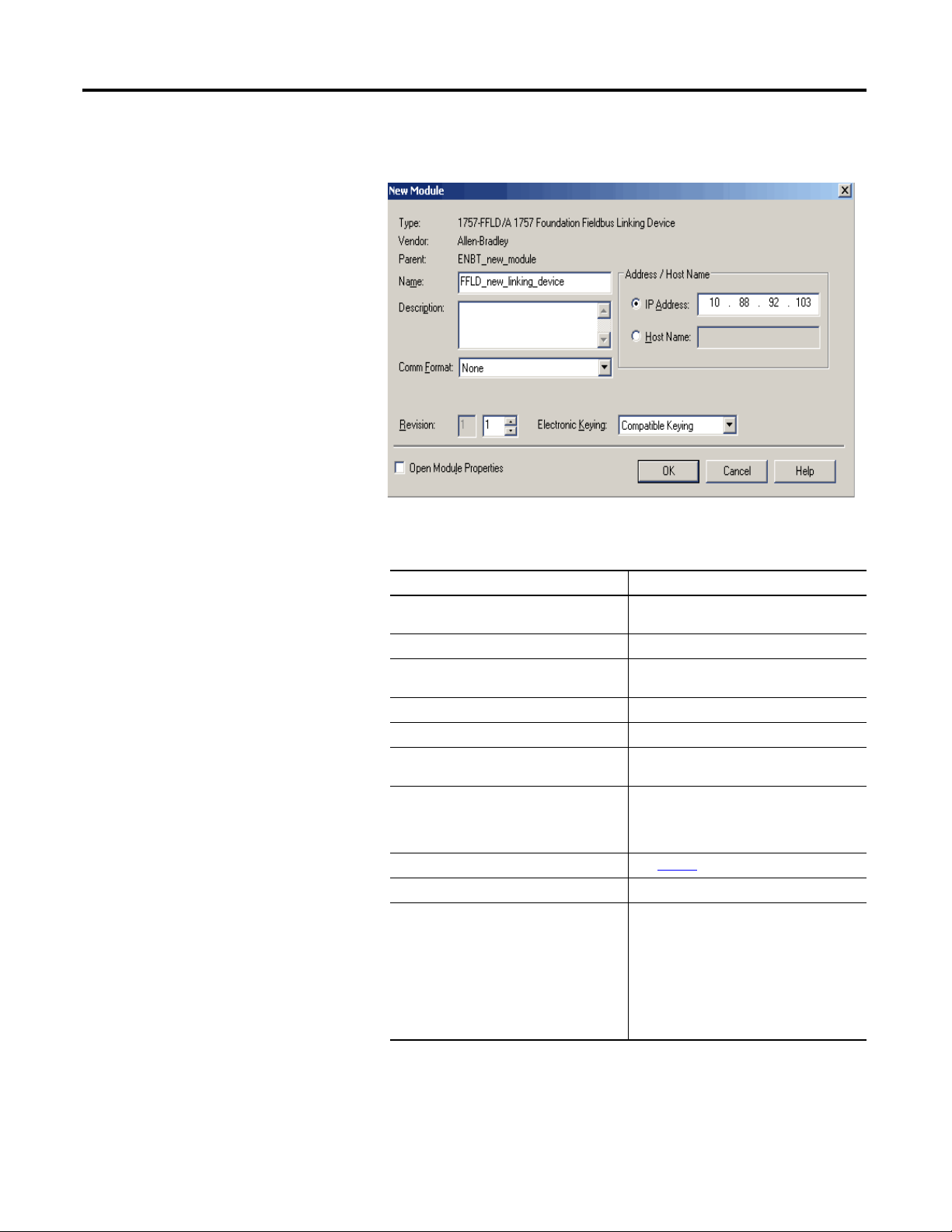
Chapter 5 Create an RSLogix 5000 Software Project
The New Module dialog box appears to let you enter the Name and
EtherNet/IP address for your linking device.
6. Configure the linking device by entering information in the New Module
dialog box.
Field Description
Type Defaults the type of module that you are
Vendor Defaults to Allen-Bradley.
Parent Defaults to the selected communication
Name Type a name for the linking device module.
Description Type a description (optional) for the module.
Comm Format Use the default or choose a communication
Revision Defaults both the Major Revision (first field)
Electronic Keying See page 94
Address/Host Name Type the EtherNet/IP address.
Open Module Properties Do one of the following based on whether
initiating.
module.
format from the pull-down menu.
and Minor Revision numbers. Choose the
appropriate pull-down menus to change the
revision numbers, if necessary.
for details.
you want to accept default configuration
settings or edit configuration data.
• To accept the default configuration
settings, make sure you clear the Open
Module Properties checkbox.
• To set up custom configuration, make sure
there is a checkmark in the Open Module
Properties checkbox.
7. Click OK.
84 Rockwell Automation Publication 1757-UM012A-EN-P - July 2011
Page 85
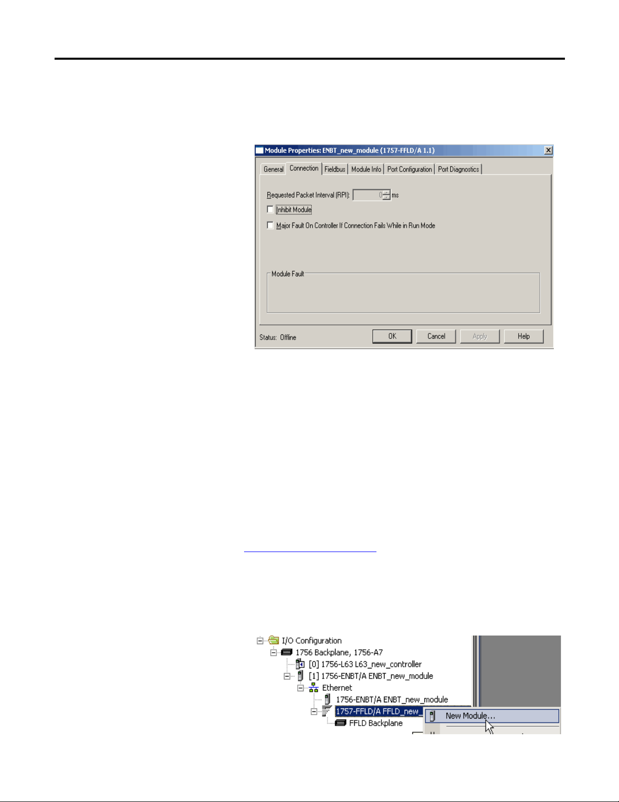
Create an RSLogix 5000 Software Project Chapter 5
The Module Properties dialog box has tabs if you checked Open Module
Properties on the New Module dialog box.
The Connection tab defaults as shown in the example.
8. Click OK.
Add the Logix Blocks
The Logix Block facilitates cascading control between a ControlLogix
environment and a fieldbus environment. The Logic Block takes signals
generated in either environment and sends them to the other.
You can use the Logix Block to send or receive 8 analog or 8 discrete signals per
Logix Block to or from a Logix controller. You can use up to 16 Logix Block
within a single linking device.
See Logix Block Module Operation
how the Logix Block module operates in a ControlLogix system.
Do these steps to add a Logix Block module to the linking device.
1. In the Controller organizer, right-click the 1757-FFLD module and
choose New Module.
in Chapter 6 for more information about
Rockwell Automation Publication 1757-UM012A-EN-P - July 2011 85
Page 86
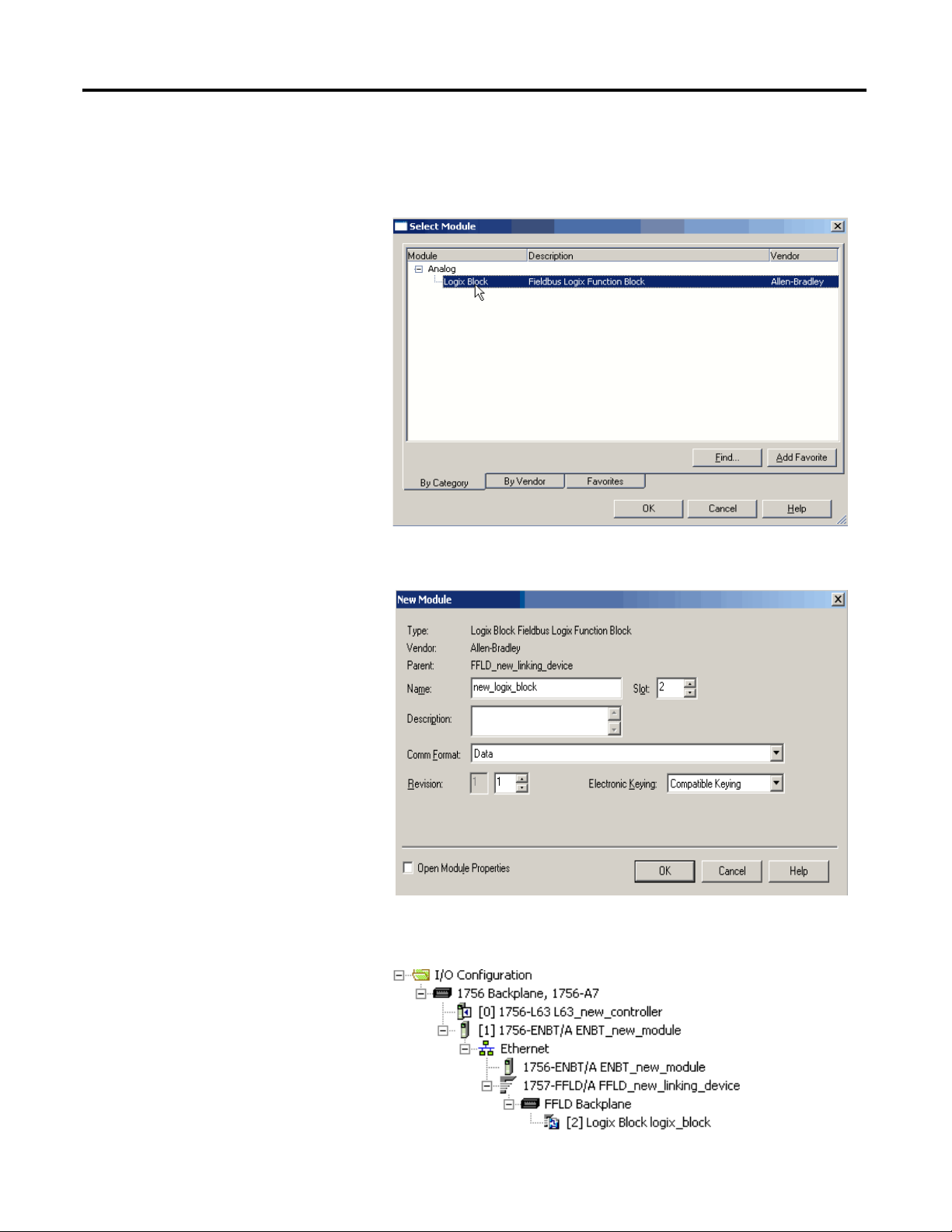
Chapter 5 Create an RSLogix 5000 Software Project
The Select Module dialog box appears.
2. Click the ‘+’ sign in front of Analog on the Select Module dialog box.
3. Select the Logix Block module, and then click OK.
The New Module dialog box appears to let you name the Logix Block and
corresponding slot number.
4. Click OK.
Your I/O Configuration tree should look similar to this example.
86 Rockwell Automation Publication 1757-UM012A-EN-P - July 2011
Page 87

Create an RSLogix 5000 Software Project Chapter 5
Configure the Linking Device and Logix Block Properties
Use the following information to configure the linking device and Logix Block
module properties.
Configure Linking Device Properties
1. In the Controller Organizer, right-click the linking device and
choose Properties.
The Module Properties dialog box appears.
In the General tab, you can rename the linking device, add a description,
set the IP address, and choose the type of electronic keying you prefer.
Rockwell Automation Publication 1757-UM012A-EN-P - July 2011 87
Page 88

Chapter 5 Create an RSLogix 5000 Software Project
2. On the Module Properties dialog box, click the Connection tab.
In this tab, you can inhibit the module and enable a major fault on the
controller if the connection fails in Run mode.
See page 92
for more information.
3. On the Module Properties dialog box, click the Fieldbus tab.
4. Click the icon to launch RSFieldbus software.
You can create a linking device in RSLogix 5000 software or RSFieldbus
software. But, you must associate the linking device with field devices on
the H1 segment in the RSFieldbus software.
See page 33
88 Rockwell Automation Publication 1757-UM012A-EN-P - July 2011
to program your linking device with field devices.
Page 89
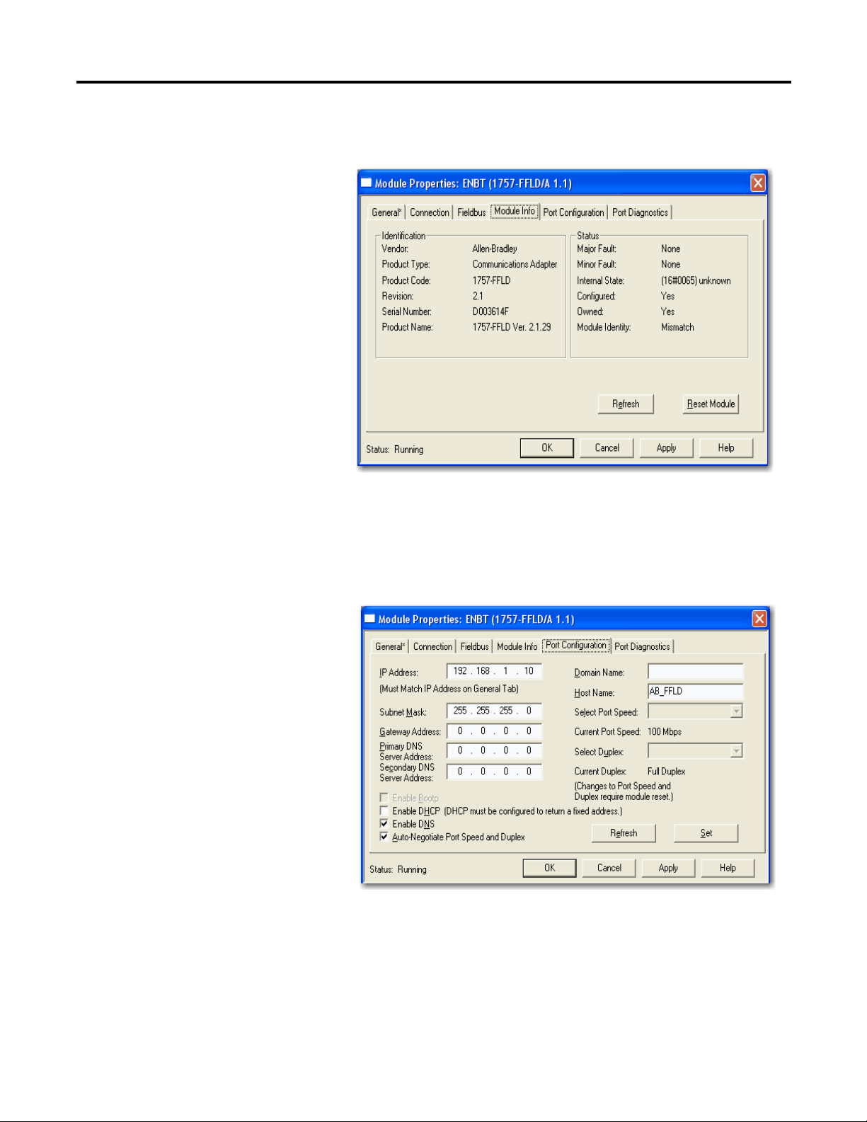
Create an RSLogix 5000 Software Project Chapter 5
5. Return to the Module Properties dialog box and click the
Module Info tab.
In this tab, you can view the module’s identification information and
module’s status.
You must be online for module details to appear.
6. On the Module Properties dialog box, click the Port Configuration tab.
In this tab, you can view or set the module’s port configuration. You must
be online for these details to appear.
If you make any changes in this tab, you must reset the module to activate
the changes.
Rockwell Automation Publication 1757-UM012A-EN-P - July 2011 89
Page 90
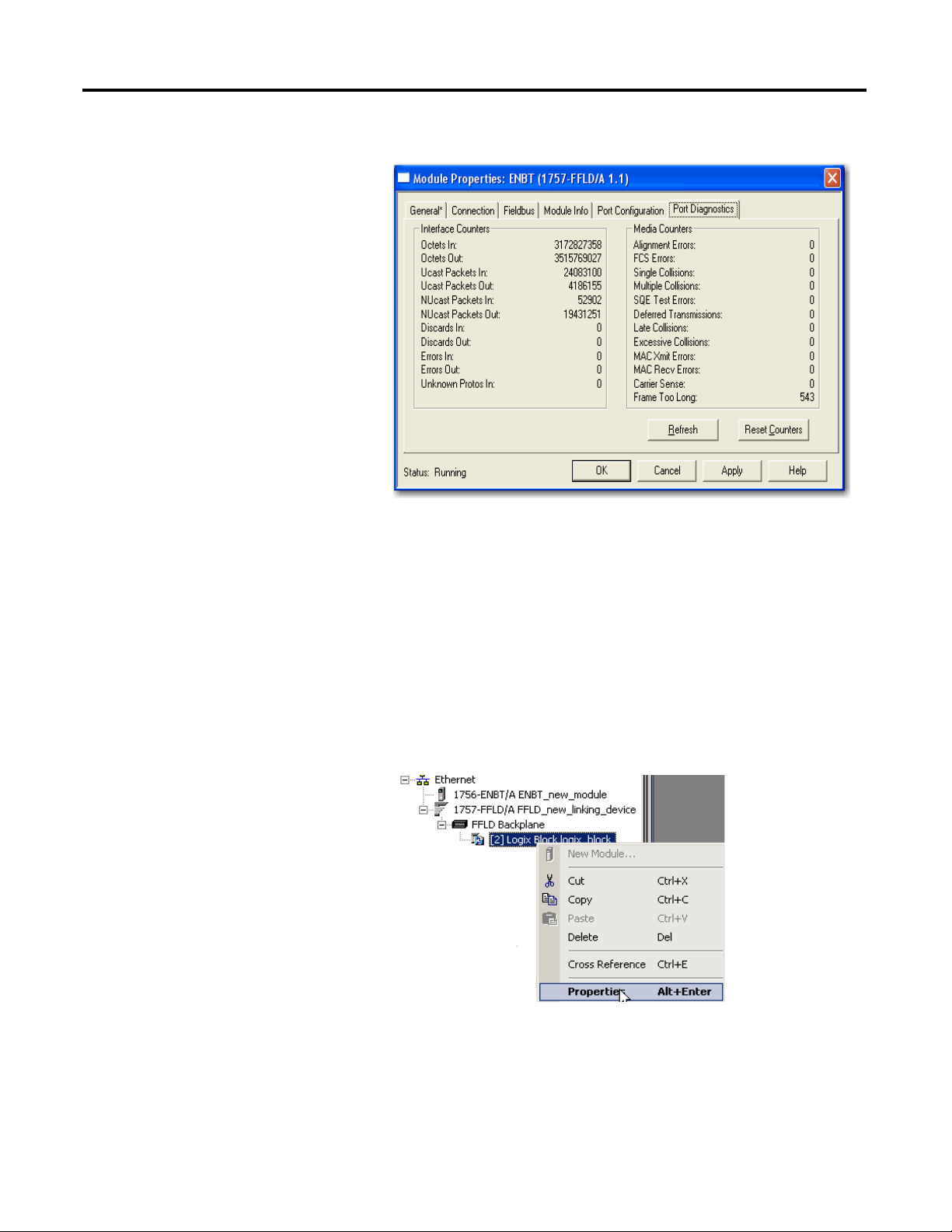
Chapter 5 Create an RSLogix 5000 Software Project
7. On the Module Properties dialog box, click the Port Diagnostics tab.
In this tab, you can view, refresh, and reset the module’s interface counters
and media counters.
You must be online for these details to appear.
Maintain Logix Block Data
Do these steps to rename your Logix Block and choose the type of electronic
keying for an existing module.
1. On the Controller Organizer, right-click the Logix Block module and
choose Properties.
90 Rockwell Automation Publication 1757-UM012A-EN-P - July 2011
Page 91
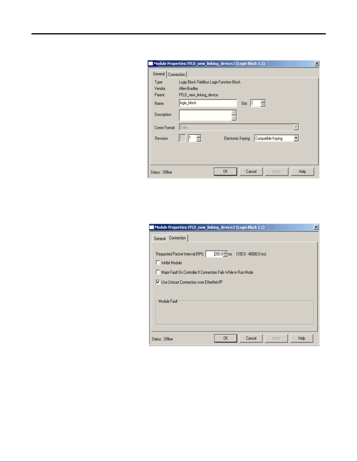
Create an RSLogix 5000 Software Project Chapter 5
The Module Properties dialog box appears.
In the General tab, you can rename the Logix Block module, change the
slot number, add a description and choose the type of electronic keying
you need.
2. On the Module Properties dialog box, click the Connection tab.
Rockwell Automation Publication 1757-UM012A-EN-P - July 2011 91
Page 92

Chapter 5 Create an RSLogix 5000 Software Project
IMPORTANT
3. Review the checkboxes on this dialog box.
Field Description
Requested Packet Interval (RPI) Choose the RPI to determine the rate at
Inhibit Module Check the box to prevent communication
Major Fault On Controller If Connection Fails
While in Run Mode
Use Unicast Connection on EtherNet/IP Displays only for analog modules using
which a communication module, such as a
1756-ENBT module, queries the block.
between the owner-controller and the
module. This option allows for maintenance
of the module without faults being reported
to the controller.
See Module Inhibiting in the ControlLogix
Analog I/O Modules User Manual,
publication 1756-UM009, for more
information.
Check the box to create a major fault if there
is a connection failure with the module while
in Run mode.
For important information on this checkbox,
see ‘Configure a Major Fault to Occur’ in the
Logix5000 Controllers Information and
Status Programming Manual,
publication 1756-PM015.
RSLogix 5000 software version 18 or later in
a remote EtherNet/IP chassis.
Use the default checkbox if there are no
other controllers in ’Listen’ mode and data is
to be sent to a specific owner-controller.
Clear the box if there are other ’listening’
controllers in the system.
Module Fault If a fault occurs, its details appear in this
section of the tab.
Adding Logix Blocks online in RSLogix 5000 software with ‘Major
Fault on Controller If Connection Fails While in Run Mode’
checked may result in faulting the controller if the Logix Block has
not been already downloaded via RSFieldbus software or the
Logix Block is configured to use a scheduled connection.
4. Click OK.
92 Rockwell Automation Publication 1757-UM012A-EN-P - July 2011
Page 93

Create an RSLogix 5000 Software Project Chapter 5
IMPORTANT
Schedule the ControlNet
Network
This section is only for the 1757-FFLDC linking device that can be set up for
scheduling data transmissions on the ControlNet network.
To select a scheduled connection for communication to the Logix Block you
must run RSNetWorx for ControlNet software to schedule the network for the
connection to begin running.
You must be offline in RSLogix 5000 software when creating your
RSNetWorx for ControlNet file for the Logix Blocks to display correctly
in RSNetWorx software.
On the Connection tab of the Module Properties dialog box, the ‘Use Scheduled
Connection over ControlNet’ box defaults with a checkmark. This parameter
works in conjunction with the RSNetWorx for ControlNet software to program
the 1757-FFLDC linking device for scheduling.
When using unscheduled connections, the ControlNet network needs to be
scheduled initially to set the network parameters (NUT, SMAX, and UMAX),
but not with the addition of each unscheduled Logix Block. Clear ‘Use
Scheduled Connection over ControlNet’ to select an unscheduled connection
for communication to the Logix Block.
There is time allotted in every network update time (NUT) for scheduled and
unscheduled communication. But, how your system is configured depends on
what information gets communicated.
A device’s critical information is guaranteed to be transmitted in the predefined
time interval (chunk) of the scheduled bandwidth. However, the unscheduled
time interval is shared by all of the nodes on the ControlNet network and
transmits messages and other non-critical information on a round-robin basis.
See the ControlNet Modules in Logix5000 Control Systems User Manual,
publication CNET-UM001
Rockwell Automation Publication 1757-UM012A-EN-P - July 2011 93
, for more information.
Page 94

Chapter 5 Create an RSLogix 5000 Software Project
Electronic Keying
The electronic keying feature automatically compares the expected module, as
shown in the RSLogix 5000 I/O Configuration tree, to the physical module
before I/O communication begins. You can use electronic keying to help prevent
communication to a module that does not match the type and revision expected.
For each module in the I/O Configuration tree, the user-selected keying option
determines if, and how, an electronic keying check is performed. Typically, three
keying options are available:
• Exact Match
• Compatible Keying
• Disable Keying
You must carefully consider the benefits and implications of each keying option
when selecting between them. For some specific module types, fewer options are
available.
Electronic keying is based on a set of attributes unique to each product revision.
When a Logix5000 controller begins communicating with a module, this set of
keying attributes is considered.
Table 4 - Keying Attributes
Attribute Description
Vendor The manufacturer of the module, for example, Rockwell Automation/Allen-Bradley.
Product Type The general type of the module, for example, communication adapter, AC drive, or digital I/O.
Product Code The specific type of module, generally represented by its catalog number, for example, 1756-IB16I.
Major Revision A number that represents the functional capabilities and data exchange formats of the module. Typically, although not always, a later,
Minor Revision A number that indicates the module’s specific firmware revision. Minor Revisions typically do not impact data compatibility but may
that is higher, Major Revision supports at least all of the data formats supported by an earlier, that is lower, Major Revision of the same
catalog number and, possibly, additional ones.
indicate performance or behavior improvement.
You can find revision information on the General tab of a module’s Properties
dialog box.
94 Rockwell Automation Publication 1757-UM012A-EN-P - July 2011
Page 95
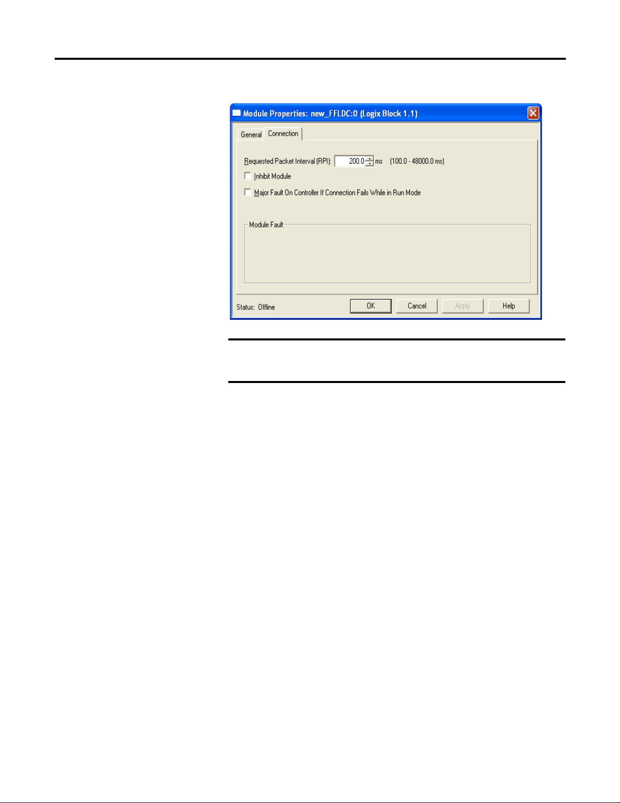
Figure 7 - General Tab
IMPORTANT
Create an RSLogix 5000 Software Project Chapter 5
Changing electronic keying selections online may cause the I/O
communication connection to the module to be disrupted and may
result in a loss of data.
Exact Match
Exact Match keying requires all keying attributes, that is, Vendor, Product Type,
Product Code (catalog number), Major Revision, and Minor Revision, of the
physical module and the module created in the software to match precisely to
establish communication. If any attribute does not match precisely, I/O
communication is not permitted with the module or with modules connected
through it, as in the case of a communication module.
Use Exact Match keying when you need the system to verify that the module
revisions in use are exactly as specified in the project, such as for use in highlyregulated industries. Exact Match keying is also necessary to enable Automatic
Firmware Update for the module via the Firmware Supervisor feature from a
Logix5000 controller.
Rockwell Automation Publication 1757-UM012A-EN-P - July 2011 95
Page 96
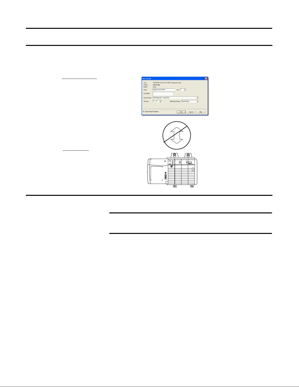
Chapter 5 Create an RSLogix 5000 Software Project
EXAMPLE
Module Configuration
Vendor = Allen-Bradley
Product Type = Digital Input
Module
Catalog Number = 1756-IB16D
Major Revision = 3
Minor Revision = 1
Communication is prevented.
Physical Module
Vendor = Allen-Bradley
Product Type = Digital Input
Module
Catalog Number = 1756-IB16D
Major Revision = 3
Minor Revision = 2
IMPORTANT
In the following scenario, Exact Match keying prevents I/O communication.
The module configuration is for a 1756-IB16D module with module revision 3.1. The physical module is a 1756-IB16D
module with module revision 3.2. In this case, communication is prevented because the Minor Revision of the module
does not match precisely.
96 Rockwell Automation Publication 1757-UM012A-EN-P - July 2011
Changing electronic keying selections online may cause the I/O
Communication connection to the module to be disrupted and may
result in a loss of data.
Compatible Keying
Compatible keying indicates that the module determines whether to accept or
reject communication. Different module families, communication adapters, and
module types implement the compatibility check differently based on the family
capabilities and on prior knowledge of compatible products.
Compatible keying is the default setting. Compatible keying allows the physical
module to accept the key of the module configured in the software, provided that
the configured module is one the physical module is capable of emulating. The
exact level of emulation required is product and revision specific.
With Compatible keying, you can replace a module of a certain Major Revision
with one of the same catalog number and the same or later, that is higher, Major
Revision. In some cases, the selection makes it possible to use a replacement that is
a different catalog number than the original. For example, you can replace a
1756-CNBR module with a 1756-CN2R module.
Page 97
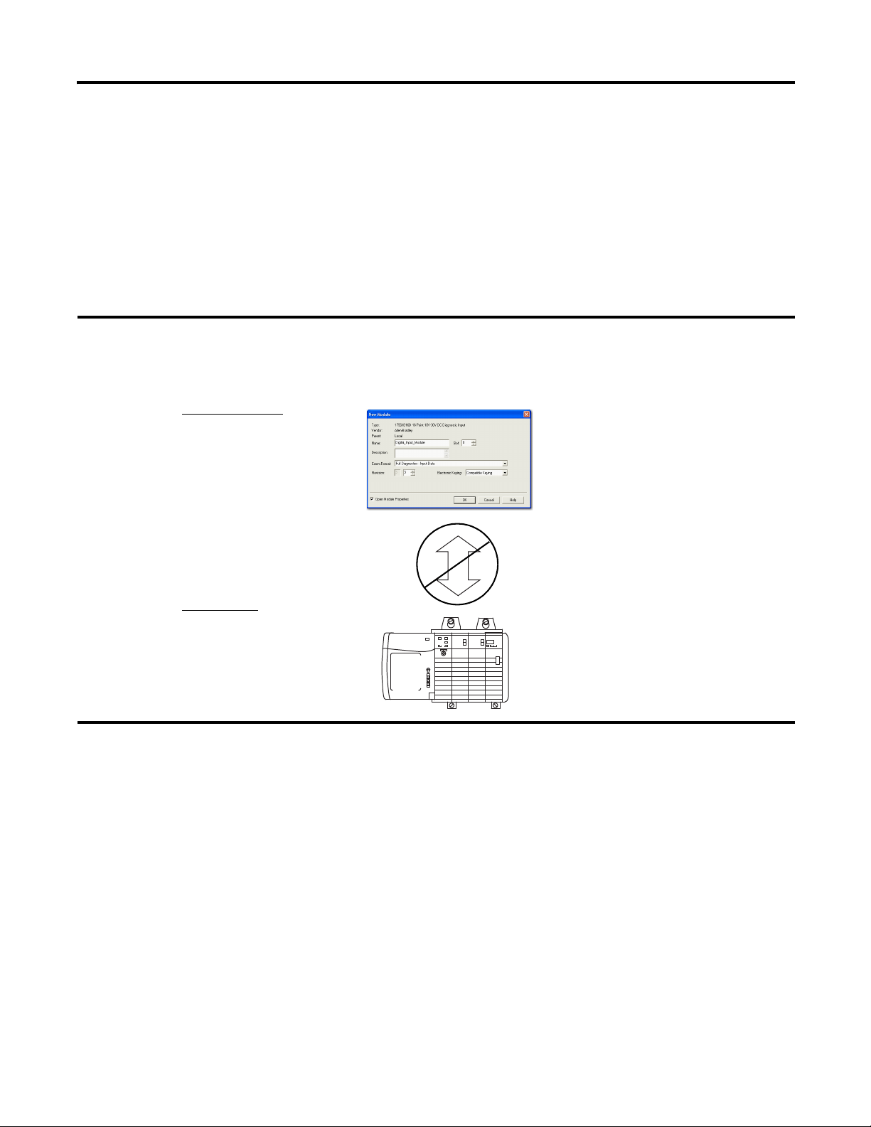
Create an RSLogix 5000 Software Project Chapter 5
EXAMPLE
Module Configuration
Vendor = Allen-Bradley
Product Type = Digital Input
Module
Catalog Number = 1756-IB16D
Major Revision = 3
Minor Revision = 3
Physical Module
Vendor = Allen-Bradley
Product Type = Digital Input
Module
Catalog Number = 1756-IB16D
Major Revision = 3
Minor Revision = 2
Communication is prevented.
Release notes for individual modules indicate the specific compatibility details.
When a module is created, the module developers consider the module’s
development history to implement capabilities that emulate those of the previous
module. However, the developers cannot know future developments. Because of
this, when a system is configured, we recommend that you configure the module
by using the earliest, that is, lowest, revision of the physical module that you
believe will be used in the system. By doing this, you can avoid the case of a
physical module rejecting the keying request because it is an earlier revision than
the one configured in the software.
In the following scenario, Compatible keying prevents I/O communication:
The module configuration is for a 1756-IB16D module with module revision 3.3. The physical module is a 1756-IB16D
module with module revision 3.2. In this case, communication is prevented because the minor revision of the module is
lower than expected and may not be compatible with 3.3.
Rockwell Automation Publication 1757-UM012A-EN-P - July 2011 97
Page 98
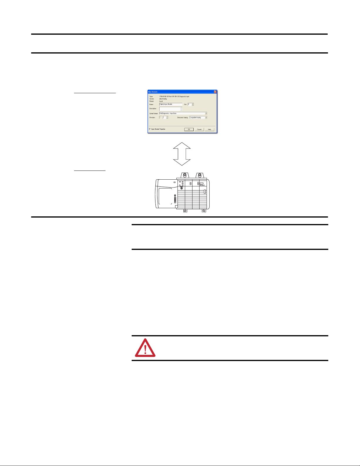
Chapter 5 Create an RSLogix 5000 Software Project
EXAMPLE
Module Configuration
Vendor = Allen-Bradley
Product Type = Digital Input
Module
Catalog Number = 1756-IB16D
Major Revision = 2
Minor Revision = 1
Physical Module
Vendor = Allen-Bradley
Product Type = Digital Input
Module
Catalog Number = 1756-IB16D
Major Revision = 3
Minor Revision = 2
Communication is allowed.
IMPORTANT
In the following scenario, Compatible keying allows I/O communication:
The module configuration is for a 1756-IB16D module with module revision 2.1. The physical module is a 1756-IB16D
module with module revision 3.2. In this case, communication is allowed because the major revision of the physical
module is higher than expected and the module determines that it is compatible with the prior major revision.
Changing electronic keying selections online may cause the I/O
communication connection to the module to be disrupted and may result
in a loss of data.
Disabled Keying
Disabled keying indicates the keying attributes are not considered when
attempting to communicate with a module. Other attributes, such as data size and
format, are considered and must be acceptable before I/O communication is
established. With Disabled keying, I/O communication may occur with a
module other than the type specified in the I/O Configuration tree with
unpredictable results. We generally do not recommend using Disabled keying.
ATTENTION: Be extremely cautious when using Disabled keying; if used
incorrectly, this option can lead to personal injury or death, property
damage, or economic loss.
If you use Disabled keying, you must take full responsibility for understanding
whether the module that is being used can fulfill the functional requirements of
the application.
98 Rockwell Automation Publication 1757-UM012A-EN-P - July 2011
Page 99
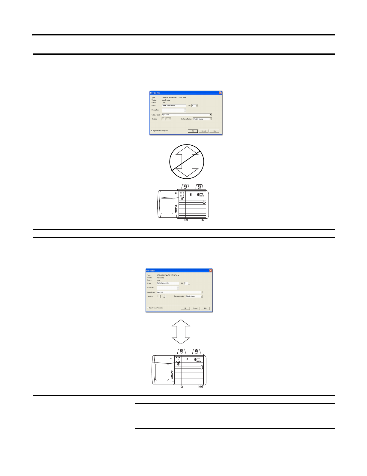
Create an RSLogix 5000 Software Project Chapter 5
EXAMPLE
EXAMPLE
Module Configuration
Vendor = Allen-Bradley
Product Type = Digital Input
Module
Catalog Number = 1756-IA16
Major Revision = 3
Minor Revision = 1
Physical Module
Vendor = Allen-Bradley
Product Type = Analog Input
Module
Catalog Number = 1756-IF16
Major Revision = 3
Minor Revision = 2
Communication is prevented.
Module Configuration
Vendor = Allen-Bradley
Product Type = Digital Input
Module
Catalog Number = 1756-IA16
Major Revision = 2
Minor Revision = 1
Physical Module
Vendor = Allen-Bradley
Product Type = Digital Input
Module
Catalog Number = 1756-IB16
Major Revision = 3
Minor Revision = 2
Communication is allowed.
IMPORTANT
In the following scenario, Disable keying prevents I/O communication:
The module configuration is for a 1756-IA16 digital input module. The physical module is a 1756-IF16 analog input
module. In this case, communication is prevented because the analog module rejects the data formats that the
digital module configuration requests.
In the following scenario, Disable keying allows I/O communication:
The module configuration is for a 1756-IA16 digital input module. The physical module is a 1756-IB16 digital input
module. In this case, communication is allowed because the two digital modules share common data formats.
Changing electronic keying selections online may cause the I/O
communication connection to the module to be disrupted and may
result in a loss of data.
Rockwell Automation Publication 1757-UM012A-EN-P - July 2011 99
Page 100

Chapter 5 Create an RSLogix 5000 Software Project
Notes:
100 Rockwell Automation Publication 1757-UM012A-EN-P - July 2011
 Loading...