

Rockwell Automation 1756-HYD02, 1756-M02AE, 1756-M02AS, 1756-M03SE, 1756- M08SE User Manual
...
User Manual
Motion Coordinate System
1756-HYD02, 1756-M02AE, 1756-M02AS, 1756-M03SE, 1756M08SE, 1756-M16SE, 1768-M04SE
Original Instructions
Motion Coordinate System
personal injury or death, property damage, or economic loss.
Attentions help you identify a hazard, avoid a hazard, and recognize the consequence.
IMPORTANT
SHOCK HAZARD: Labels may be on or inside the equipment, for example, a drive or motor, to alert people that dangerous voltage may be present.
temperatures.
for Personal Protective Equipment (PPE).
Important User Information
Read this document and the documents listed in the additional resources section about installation, configuration, and
operation of this equipment before you install, configure, operate, or maintain this product. Users are required to familiarize
themselves with installation and wiring instructions in addition to requirements of all applicable codes, laws, and standards.
Activities including installation, adjustments, putting into service, use, assembly, disassembly, and maintenance are required to
be carried out by suitably trained personnel in accordance with applicable code of practice.
If this equipment is used in a manner not specified by the manufacturer, the protection provided by the equipment may be
impaired.
In no event will Rockwell Automation, Inc. be responsible or liable for indirect or consequential damages resulting from the use
or application of this equipment.
The examples and diagrams in this manual are included solely for illustrative purposes. Because of the many variables and
requirements associated with any particular installation, Rockwell Automation, Inc. cannot assume responsibility or liability for
actual use based on the examples and diagrams.
No patent liability is assumed by Rockwell Automation, Inc. with respect to use of information, circuits, equipment, or software
described in this manual.
Reproduction of the contents of this manual, in whole or in part, without written permission of Rockwell Automation, Inc., is
prohibited.
Throughout this manual, when necessary, we use notes to make you aware of safety considerations.
WARNING: Identifies information about practices or circumstances that can cause an explosion in a hazardous environment, which may lead to
ATTENTION: Identifies information about practices or circumstances that can lead to personal injury or death, property damage, or economic loss.
Identifies information that is critical for successful application and understanding of the product.
Labels may also be on or inside the equipment to provide specific precautions.
BURN HAZARD: Labels may be on or inside the equipment, for example, a drive or motor, to alert people that surfaces may reach dangerous
ARC FLASH HAZARD:
will cause severe injury or death. Wear proper Personal Protective Equipment (PPE). Follow ALL Regulatory requirements for safe work practices and
Labels may be on or inside the equipment, for example, a motor control center, to alert people to potential Arc Flash. Arc Flash
2 Rockwell Automation Publication MOTION-UM002G-EN-P - October 2020

Summary of changes
Topic Name
Reason
J1J2J3J6 Coordinate System.
This manual contains new and updated information. Use these reference
tables to locate new or changed information.
Grammatical and editorial style changes are not included in this summary.
Global changes
This table contains a list of topics changed in this version, the reason for the
change, and a link to the topic that contains the changed information.
New or enhanced features
Configure the SCARA Independent J1J2J3J6 Coordinate System on page 67 Added section to configure a SCARA Indepent
Rockwell Automation Publication MOTION-UM002G-EN-P - October 2020 3


Table of Contents
Summary of changes
Create and configure a
coordinate system
Cartesian coordinate system
Cartesian coordinate
system examples
Preface
Before you begin ......................................................................................... 9
Sample projects ........................................................................................... 9
Additional resources ..................................................................................10
Chapter 1
Create a Coordinate System...................................................................... 11
Coordinate System Properties dialog box ............................................... 13
Edit Coordinate System properties .......................................................... 13
Geometry tab ........................................................................................ 14
Chapter 2
Program coordinate system with no orientation .................................... 17
Blended moves and termination types with MCLM or MCCM .............. 17
Example ladder diagram for blended instructions ........................... 18
Bit States at transition points of blended move by using actual
tolerance or no settle ............................................................................ 19
Bit States at transition points of blended move by using no decel . 20
Bit states at transition points of blended move by using command
tolerance ............................................................................................... 21
Bit states at transition points of blended move by using follow
contour velocity constrained or unconstrained ............................... 22
Choose a termination type ................................................................. 22
Chapter 3
Configure an Articulated Independent robot .......................................... 33
Establish reference frame for an articulated independent robot .......... 33
Methods to establish a reference frame for an articulated independent
robot ............................................................................................................ 35
Method 1 - Establish a reference frame .............................................. 36
Method 2 - Establish a reference frame using a MRP instruction ... 36
Configuration parameters for Articulated Independent robot .............. 37
Link lengths for Articulated Independent robot .............................. 38
Base Offsets .......................................................................................... 39
End-Effector Offsets for Articulated Independent robot ................. 39
Configure Delta robot geometries ........................................................... 40
Configure a Delta Three-dimensional robot ...................................... 41
Establish the reference frame for a Delta Three-dimensional robot
robot..................................................................................................... 42
Calibrate a Delta Three-dimensional robot ...................................... 42
Alternate method for calibrating a Delta Three-dimensional robot 43
Rockwell Automation Publication MOTION-UM002G-EN-P - October 2020 5

Table of Contents
Configure Zero Angle Orientations for Delta Three-dimensional
robot ...................................................................................................... 43
Identify the work envelope for a Delta Three-dimensional robot ....44
Define configuration parameters for a Delta Three-dimensional
robot ...................................................................................................... 45
Configure a Delta Two-dimensional robot ....................................... 46
Establish the reference frame for a Delta Two-dimensional robot .. 47
Calibrate a Delta Two-dimensional robot .......................................... 47
Identify the work envelope for a Delta Two-Dimensional robot ..... 48
Define configuration parameters for a Delta Two-dimensional
robot ..................................................................................................... 48
Configure a SCARA Delta robot ............................................................... 49
Establish the reference frame for a SCARA Delta robot .................. 49
Calibrate a SCARA Delta robot ........................................................... 50
Identify the work envelope for a SCARA Delta robot ....................... 50
Define configuration parameters for a SCARA Delta robot ............. 51
Configure a Delta robot with a Negative X1b offset .......................... 51
Arm solutions ............................................................................................. 52
Left-arm and right-arm solutions for two-axes robots ..................... 53
Solution mirroring for three-dimensional robots ................................... 53
Change the robot arm solution ................................................................. 54
Plan for singularity ..................................................................................... 55
Encounter a no-solution position ............................................................. 55
Error conditions ......................................................................................... 55
Configure an Articulated Dependent robot .............................................56
Reference frame for Articulated Dependent robots ................................56
Methods to establish a reference frame for an articulated independent
robot ........................................................................................................... 58
Method 1 - Establish a reference frame using zero angle
orientation............................................................................................59
Method 2 - Establish a reference frame ............................................. 60
Work envelope for articulated independent robot ................................. 60
Configuration parameters for Articulated Dependent robot ................. 61
Link lengths for Articulated Dependent robot ................................. 62
Base offsets for Articulated Independent robot ............................... 62
Configure a Cartesian Gantry robot ......................................................... 63
Introduction ............................................................................................... 63
Establish the reference frame for a Cartesian Gantry robot ............ 63
Identify the work envelope for a Cartesian Gantry robot ................ 64
Define configuration parameters for a Cartesian Gantry robot ..... 64
6 Rockwell Automation Publication MOTION-UM002G-EN-P - October 2020

Table of Contents
Configure a Cartesian H-bot
Coordinate system attributes
Arm solutions
Index
Chapter 4
Configure a Cartesian H-bot robot ..........................................................65
Establish the reference frame for a Cartesian H-bot ....................... 66
Identify the work envelope for a Cartesian H-bot ............................ 66
Define configuration parameters for a Cartesian H-bot robot ....... 66
Configure a SCARA Independent Robot ................................................. 66
Configure the SCARA Independent J1J2J3J6 Coordinate System ........... 67
Configuration Parameters for the Robot ................................................. 67
Link Lengths for SCARA Independent J1J2J3J6 Robot ...................... 68
Zero Angle Orientations for SCARA Independent J1J2J3J6 Robot ... 68
Ball Screw Coupling for SCARA Independent J1J2J3J6 Robot .......... 70
Robot Configuration for SCARA Independent J1J2J3J6 Robot ......... 74
Robot Configuration in MCPM instruction ................................ 75
Robot Configuration in MCTPO instruction ............................... 75
Robot Configuration Example ...................................................... 76
Identify the Work Envelope for the Robot ........................................ 78
Maximum Joint Limits condition for SCARA Independent J1J2J3J6
robot ...................................................................................................... 79
Configure the Joint Limits ............................................................ 79
Work and Tool Frame offset limits for SCARA Independent J1J2J3J6
robot ...................................................................................................... 79
Sample Project for SCARA Independent J1J2J3J6 Robot .................. 80
Appendix A
Coordinate system attributes ................................................................... 81
Appendix B
Solution mirroring for three-dimensional robots ................................. 87
Change arm solution ................................................................................ 88
Change arm solution example ........................................................... 88
Singularity ................................................................................................. 88
Rockwell Automation Publication MOTION-UM002G-EN-P - October 2020 7


If you want to
Use this instruction
within a Cartesian coordinate system.
within a Cartesian coordinate system.
Stop the axes of a coordinate system or cancel a transform.
Motion Coordinated Stop (MCS)
Initiate a controlled shutdown of all of the axes of the specified coordinate system.
Motion Coordinated Shutdown (MCSD)
Start a transform that links two coordinate systems together.
Motion Coordinated Transform (MCT)
incorporates translation and orientation in its position transformation.
system.
second coordinate system.
state to the axis ready state and clear the axis faults.
axes within a Cartesian coordinate system.
Before you begin
Sample projects
Preface
This manual provides information on how to configure various coordinated
motion applications. Use the following table to choose a motion coordinated
instruction. Information about the coordinate instructions can be found in
the Logix5000™ Controllers Motion Instruction Reference Manual,
publication MOTION-RM002.
Initiate a single or multi-dimensional linear coordinated move for the specified axes
Initiate a two- or three-dimensional circular coordinated move for the specified axes
Initiate a change in path dynamics for coordinate motion active on the specified
coordinate system.
Start a transform that links to coordinate systems together. The MCTO instruction
Calculate the position of one coordinate system with respect to another coordinate
Calculate the position of a point in one coordinate system to the equivalent point in a
Initiate a reset of all of the axes of the specified coordinate system from the shutdown
Start a single or multi-dimensional linear coordinated path move (CP) for the specified
(1) Instruction cannot be used with SoftLogix™ controllers.
(2) Instruction only available for Compact GuardLogix 5380, CompactLogix
5380, CompactLogix 5480, ControlLogix 5580, and GuardLogix 5580
controllers.
Motion Coordinated Linear Move (MCLM)
Motion Coordinated Circular Move (MCCM)
Motion Coordinated Change Dynamics (MCCD)
(1)
Motion Coordinated Transform with Orientation (MCTO)
Motion Calculate Transform Position (MCTP)
Motion Coordinated Transform Position with Orientation (MCTPO)
Motion Coordinated Shutdown Reset (MCSR)
Motion Coordinated Path Move (MCPM)
(1)
(2)
(2)
(2)
This manual is a redesigned manual from publication LOGIX-UM002. A
companion manual is available called the SERCOS and Analog Motion
Configuration and Start-Up User Manual, publication MOTION-UM001. For
CIP motion configuration information, see the CIP Motion Configuration and
Startup User Manual, publication MOTION-UM003. If you have any
comments or suggestions, please see the back cover of this manual.
The Rockwell Automation sample project's default location is:
c:\Users\Public\Public Documents\Studio
5000\Sample\ENU\v<current_release>\Rockwell Automation
There is a PDF file name Vendor Sample Projects that explains how to work
with the sample projects. Free sample code is available
at http://samplecode.rockwellautomation.com/
The Vendor Sample Projects.pdf default location is:
Rockwell Automation Publication MOTION-UM002G-EN-P - October 2020 9
.
Preface
Sample Projects from the Help menu.
Resource
Description
Logix5000 controller.
publication 1756-RM003
controller.
5580 and GuardLogix 5580 controllers.
CompactLogix™ system.
5000 Logix Designer application.
Safety Reference Manual, publication 1756-RM012
Compact GuardLogix 5380 controllers in Studio 5000 Logix Designer® applications.
4.1
ge
Additional resources
c:\Users\Public\Public Documents\Studio
5000\Sample\ENU\v<current_release>\Third Party Products
Tip: To access the Vendor Sample Projects.pdf file from Logix Designer application, click
These documents contain additional information concerning related
Rockwell Automation products. You can view or download publications
at http://literature.rockwellautomation.com
.
Sercos and Analog Motion Configuration and Startup User Manual,
publication MOTION -UM001
>l5k> Controllers Motion Instructions Reference Manual,
publication MOTION-RM002
Integrated Motion on the Ethernet/IP Network: Configuration and Startup
User Manual, publication MOTION-UM003
Logix5000 Controllers Common Procedures, publication 1756-PM001 Provides detailed and comprehensive information about how to program a
Logix5000 Controllers General Instructions Reference Manual,
Describes how to configure a motion application and to start up your motion
solution by using Logix5000 motion modules.
Provides a programmer with details about motion instructions for a Logix-based
controller.
Describes how to configure an integrated motion application and to start up your
motion solution by using Studio 5000 Logix Designer® application.
Provides a programmer with details about general instructions for a Logix-based
Vendor
Logix5000 Controllers Process and Drives Instructions Reference
Manual, publication 1756-RM006.
ControlLogix System User Manual, publication 1756-UM001 Describes the necessary tasks to install, configure, program, and operate a
ControlLogix 5580 and GuardLogix 5580 Controllers User Manual,
publication 1756-UM543
CompactLogix 5370 Controllers User Manual, publication 1769-UM021 Describes the necessary tasks to install, configure, program, and operate a
GuardLogix Controllers User Manual, publication 1756-UM020 Describes the GuardLogix®-specific procedures you use to configure, operate, and
GuardLogix 5570 and Compact GuardLogix 5370 Controller Systems
Safety Reference Manual, publication 1756-RM099
GuardLogix 5580 and Compact GuardLogix 5380 Controller Systems
Industrial Automation Wiring and Grounding Guidelines, publication 1770-
Product Certifications
www.rockwellautomation.com/global/certification/overview.pa
website,
Provides a programmer with details about process and drives instructions for a
Logix-based controller.
ControlLogix® system.
Provides complete information on how to install, configure, select I/O modules,
manage communication, develop applications, and troubleshoot the ControlLogix
troubleshoot the controller.
Contains detailed requirements for achieving and maintaining SIL 3/PLe with the
GuardLogix 5570 or CompactLogix 5370 controller safety system, using the Studio
Provides information on safety application requirements for GuardLogix 5580 and
Provides general guidelines for installing a Rockwell Automation industrial system.
Provides declarations of conformity, certificates, and other certification details.
10 Rockwell Automation Publication MOTION-UM002G-EN-P - October 2020
Create a Coordinate System
Chapter 1
Create and configure a coordinate system
Use the Coordinate System tag to set the attribute values used by the Multi-
Axis Coordinated Motion instructions in motion applications. Create the
Coordinate System tag before executing any of the Multi-Axis Coordinated
Motion instructions.
The Coordinate System tag:
• Defines the COORDINATE_SYSTEM data type
• Associates the Coordinate System to a Motion Group
• Associates the axes to the Coordinate System
• Sets the dimension
• Defines the values used by the operands of the Multi-Axis Motion
Instructions
Configuring the Coordinate System tag defines the values for Coordination
Units, Maximum Speed, Maximum Acceleration, Maximum Deceleration,
Actual Position Tolerance, and Command Position Tolerance.
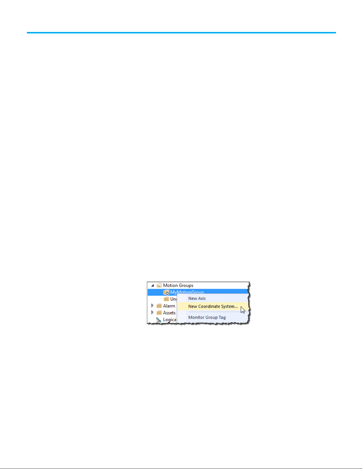
To create a coordinate system:
1. In the Controller Organizer, right-click the motion group and select
New Coordinate System.
Rockwell Automation Publication MOTION-UM002G-EN-P - October 2020 11
Chapter 1 Create and configure a coordinate system
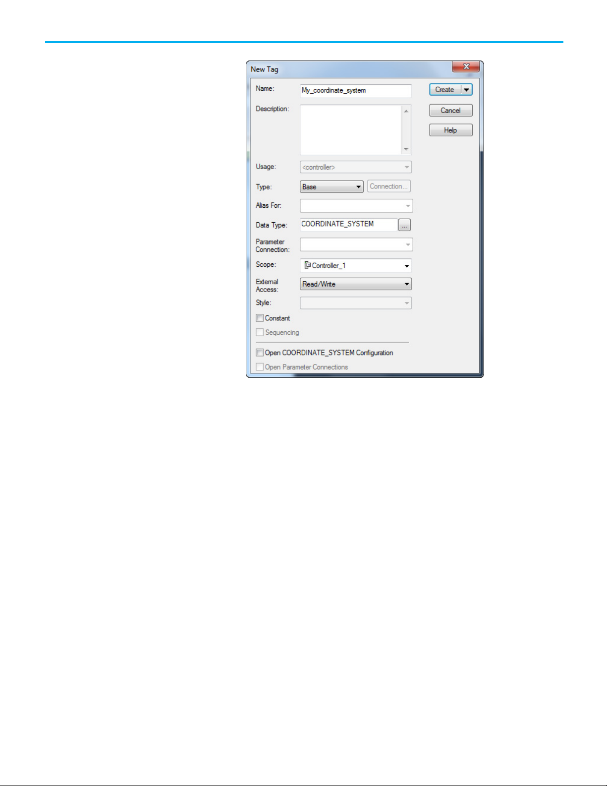
The New Tag dialog box opens.
2. In Name, enter the name of the coordinate system.
3. [optional] In Description, type a description of the coordinate system.
4. In Type, select the type of tag to create. For a coordinate system, the
only valid choices are:
• Base - Refers to a normal tag and is the default
• Alias - Refers to a tag that references another tag with the same
definition
5. In Data Type, select COORDINATE_SYSTEM.
6. In External Access, select whether the tag has None, Read/Write, or
Read Only access from external applications such as HMIs.
7. Select Constant to prevent executing logic from writing values to the
tag. Refer to the online help for more information about the Constant
check box.
8. Select Open COORDINATE_SYSTEM to open the Coordinate System
Wizard after creating the tag.
Once the tag is created, double-click the coordinate system to open the
Coordinate System Properties dialog box to edit the coordinate system
tag.
9. Select Create to create the tag.
12 Rockwell Automation Publication MOTION-UM002G-EN-P - October 2020

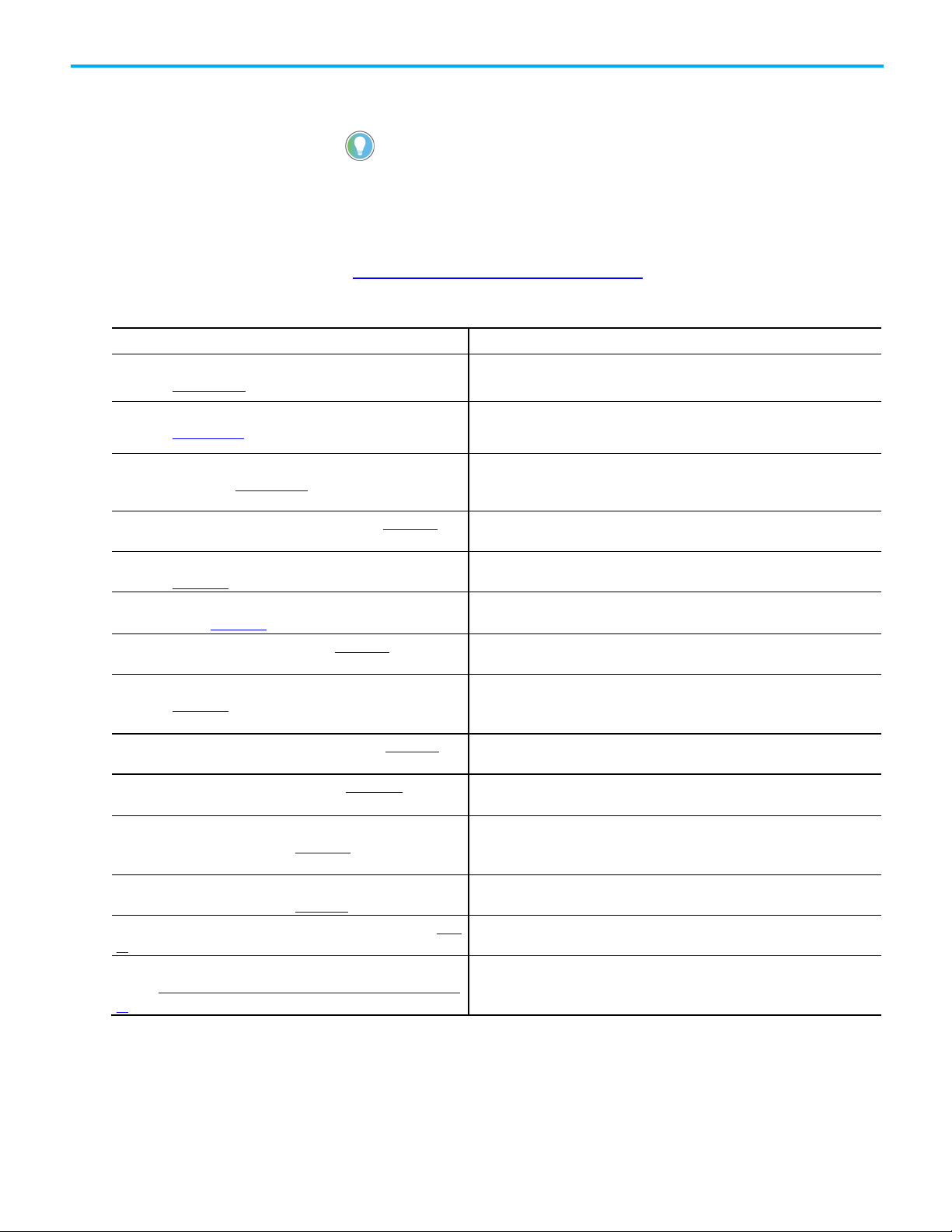
Wizard/Coordinate System
Description
geometry.
the geometry.
Dynamics
The
tab configures the Vector, Actual and Command Position Tolerance, and Orientation values for a Cartesian
coordinate system.
Tag
The
tab is used to rename the tag, edit the description, and review the
, and
information.
Coordinate System
Chapter 1 Create and configure a coordinate system
See also
Coordinate System Properties dialog box on page 13
Use the Coordinate System Wizard or Coordinate System Properties dialog
box to configure the Coordinate System tag. The dialog box contains tabs for
Properties dialog box
Properties tab
General The General tab is used to:
• Associate the tag to a Motion Group.
• Select the coordinate system type.
• Select the coordinate definition for the geometry type.
• If applicable, specify the number of dimensions and transform dimensions for the geometry type.
• Enter the associated axis information.
• Select whether to update Actual Position values of the coordinate system automatically during operation.
Geometry The Geometry tab configures key attributes related to non-Cartesian geometry and shows the bitmap of the associated
Offset The Offset tab configures the offsets for the base and end effector. This tab shows the bitmaps for the offsets related to
configuring different facets of the Coordinate System.
Units The Units tab defines the Coordination Units and the Conversion Ratios.
Dynamics
Joints The Joints tab defines the Joints Conversion ratios.
Motion Planner The Motion Planner tab enables or disables Master Delay Compensation or Master Position Filter.
Tag
Tag Type, Data Type
Edit Coordinate System
Use the Coordinate System Properties dialog box to modify an existing
Coordinate System or configure the Coordinate System.
properties
To edit the Coordinate System properties:
1. In the Controller Organizer, expand the Motion Group folder, and
double-click the Coordinate System, or right-click the Coordinate
System and select Properties.
2. Use the tabs in the Coordinate System Properties dialog box to make
the appropriate changes. An asterisk appears on the tab to indicate
that changes have been made but not implemented.
3. Click Apply to save the changes. To exit without saving any changes,
click Cancel.
Scope
Rockwell Automation Publication MOTION-UM002G-EN-P - October 2020 13
See also
Coordinate System Properties dialog box on page 13
Chapter 1 Create and configure a coordinate system
IMPORTANT
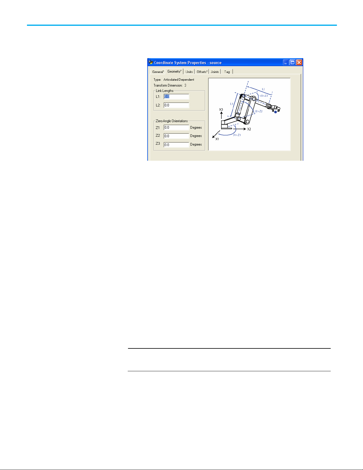
Geometry tab
The Geometry tab of the Coordinate System Properties is where you can
specify the link lengths and zero angle orientation values for articulated
robotic arms.
The graphic displayed on this tab shows a typical representation of the type of
coordinate system you selected on the General tab. Your robot should look
similar to the one shown in the graphic, but may be somewhat different
depending on your application.
Link Lengths box
The Link Lengths box displays boxes to let you specify a value for the length of
each link in an articulated robotic arm (coordinate system). The measurement
units for the articulated coordinate system are defined by the measurement
units configured for the affiliated Cartesian coordinate system. The two
coordinate systems are linked or affiliated with each other by an MCT
instruction.
When specifying the link length values, be sure that the values are calculated
by using the same measurement units as the linked Cartesian coordinate
system. For example, if the manufacturer specifies the robot link lengths by
using millimeter units and you want to configure the robot by using inches,
then you must convert the millimeter link measurements to inches and enter
the values in the appropriate Link Length boxes.
Be sure that the link lengths specified for an articulated coordinate system are in the
same measurement units as the affiliated Cartesian coordinate system. Your system
will not work properly if you are using different measurement units.
The number of boxes available for configuration in the Link Lengths box is
determined by values entered on the General tab for the type of coordinate
system, total coordinate system dimensions, and transform dimensions. The
link identifiers are L1 and L2 in the corresponding graphic. These boxes are
not configurable for a Cartesian coordinate system.
14 Rockwell Automation Publication MOTION-UM002G-EN-P - October 2020

Chapter 1 Create and configure a coordinate system
Zero Angle Orientations box
The Zero Angle Orientation box is the rotational offset of the individual joint
axes. If applicable, enter the offset value in degrees for each joint axis. The
number of available boxes is determined by the coordinate dimension value
entered on the General tab. The angle identifiers are Z1, Z2, and Z3 in the
corresponding graphic.
Rockwell Automation Publication MOTION-UM002G-EN-P - October 2020 15


Instruction
Description
axes within a Cartesian coordinate system.
axes within a Cartesian coordinate system.
two coordinate systems together.
Program coordinate system
with no orientation
Blended moves and
Chapter 2
Cartesian coordinate system
Use this information to configure a Cartesian coordinate system.
See also
Program coordinate system with no orientation on page 17
Use these multi-axis coordinated motion instructions to perform linear and
circular moves in single and multidimensional spaces. A Cartesian coordinate
system with no orientation in the Logix Designer application can include one,
two, or three axes.
termination types with
MCLM or MCCM
Motion Coordinated Linear Move (MCLM) Use the MCLM instruction to start a single or multi-
dimensional linear coordinated move for the specified
Motion Coordinated Circular Move (MCCM) Use the MCCM instruction to initiate a two or three-
dimensional circular coordinated move for the specified
Motion Coordinated Transform (MCT) Use the MCT instruction to start a transform that links
Motion Calculate Transform Position (MCTP) Use the MCTP instruction to calculate the position of a
point in one coordinate system to the equivalent point in
a second coordinate system.
See the Logix 5000 Motion Controllers Instructions Reference Manual,
publication MOTION-RM002, for more information about the MCLM,
MCCM, MCT, and MCTP instructions.
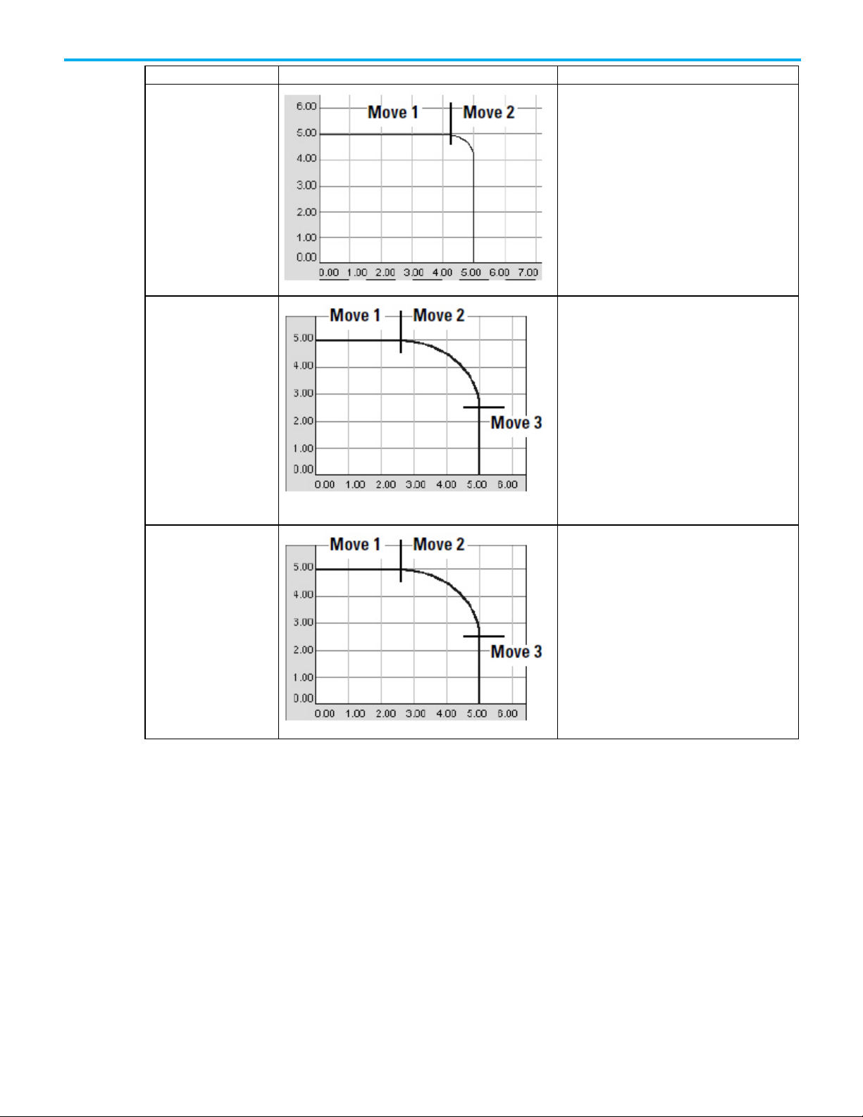
To blend two MCLM or MCCM instructions, start the first one and queue the
second one. The tag for the coordinate system gives two bits for queuing
instructions.
• MovePendingStatus
• MovePendingQueueFullStatus
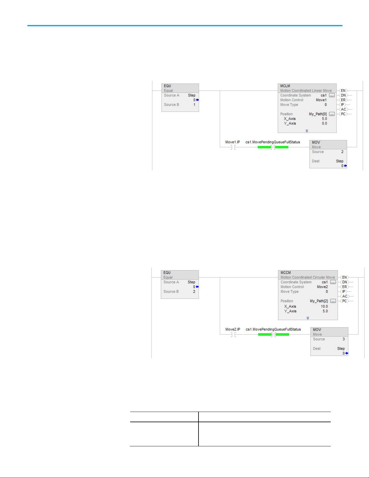
For example, the following ladder diagram uses coordinate system cs1 to
blend Move1 into Move2.
Rockwell Automation Publication MOTION-UM002G-EN-P - October 2020 17
See also
Example ladder diagram for blended instructions on page 18
Chapter 2 Cartesian coordinate system
When
Then
Example ladder diagram for
If Step = 1, then:
blended instructions
Move1 starts and moves the axes to a position of 5, 0.
and once Move1 is in process, and there is room to queue another move, then:
Step = 2.
If Step = 2, then:
Move1 is already happening.
Move2 goes into the queue and waits for Move1 to complete.
When Move1 is complete:
Move2 moves the axes to a position of 10, 5.
And once Move2 is in process and there is room in the queue:
Step = 3.
When an instruction completes, it is removed from the queue and there is
space for another instruction to enter the queue. Both bits always have the
same value because you can queue only one pending instruction at a time. If
the application requires several instructions to be executed in sequence, the
bits are set by using these parameters.
18 Rockwell Automation Publication MOTION-UM002G-EN-P - October 2020
One instruction is active and a
second instruction is pending in
the queue
• MovePendingStatus bit = 1
• MovePendingQueueFullStatus bit = 1
•
You cannot queue another instruction
When
Then
Bit States at transition
Chapter 2 Cartesian coordinate system
An active instruction completes
and leaves the queue
• MovePendingStatus bit = 0
• MovePendingQueueFullStatus bit = 0
•
You can queue another instruction
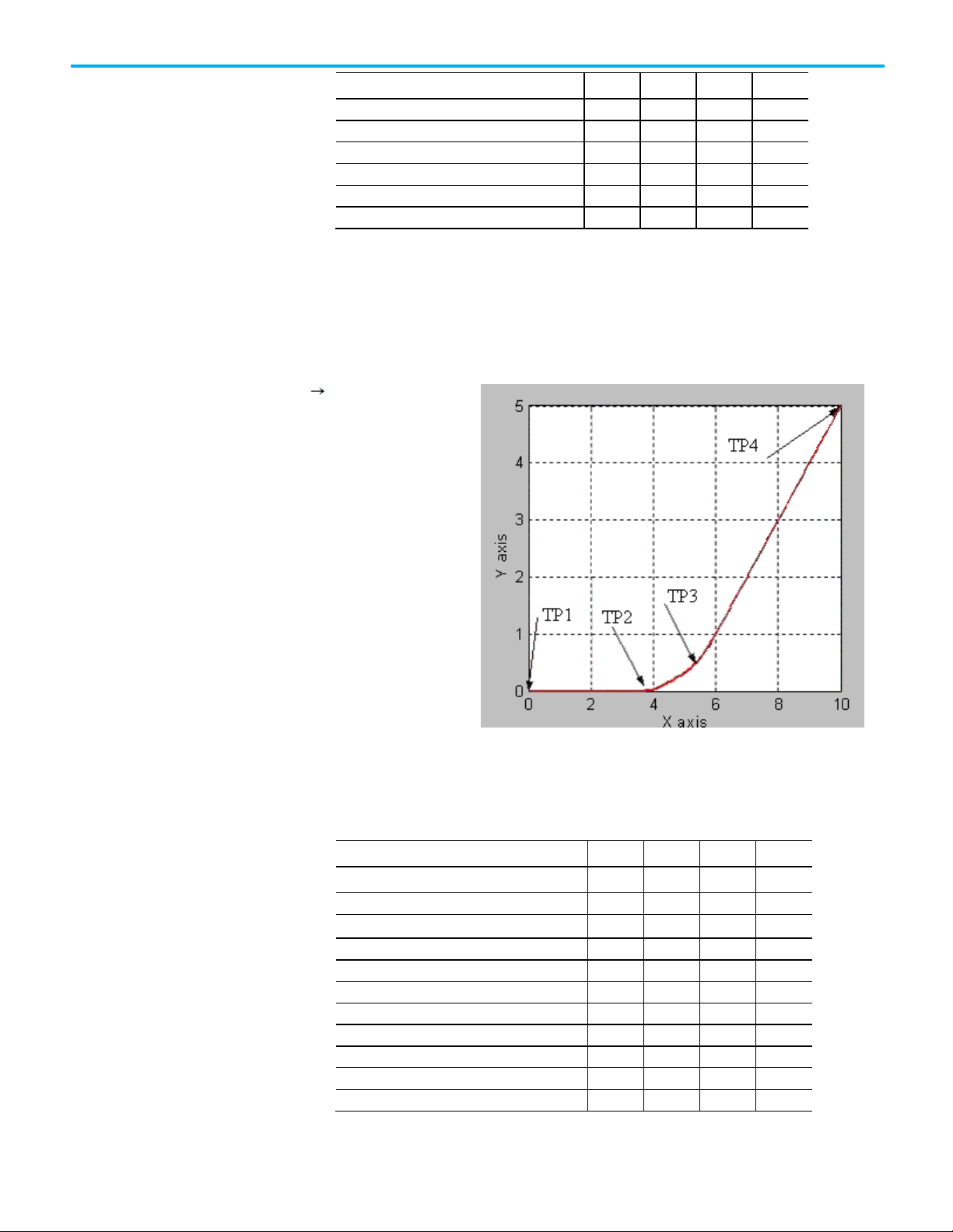
The termination type operand for the MCLM or MCCM instruction specifies
how the currently executing move gets terminated. These illustrations show
the states of instruction bits and coordinate system bits that get affected at
various transition points (TP).
The termination types are:
• 0 - Actual tolerance
• 1 - No Settle
• 2 - Command Tolerance
• 3 - No Decel
• 4 - Follow Contour Velocity Constrained
• 5 - Follow Contour Velocity Unconstrained
• 6 - Command Tolerance Programmed
See also
points of blended move by
using actual tolerance or no
settle
linear linear move
Termination types on page 22
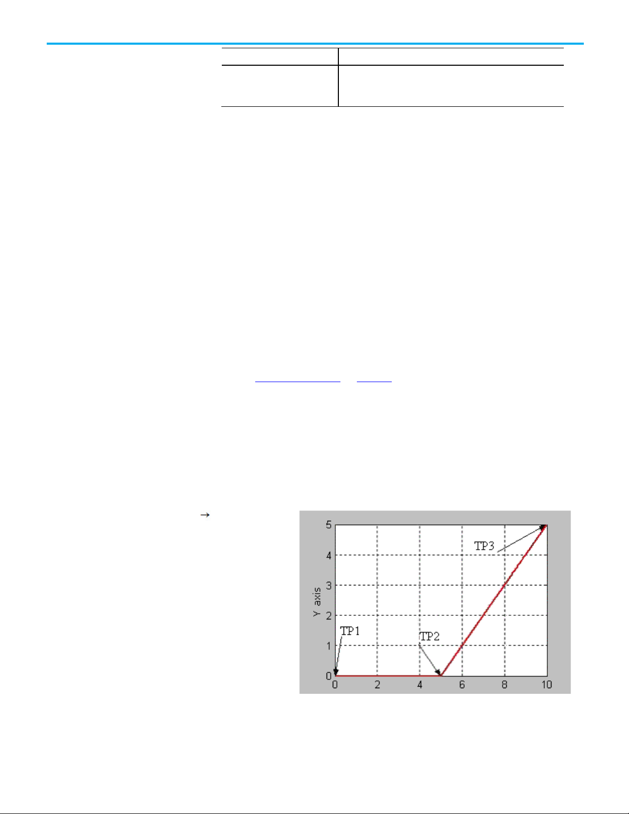
This topic lists the bit states at transition points of Blended Move by using
Actual Tolerance or No Settle.
Rockwell Automation Publication MOTION-UM002G-EN-P - October 2020 19
This table shows the bit status at the various transition points shown in the
preceding graph with termination type of Actual Tolerance or No Settle.
Chapter 2 Cartesian coordinate system
Bit
TP1
TP2
TP3
Move1.IP
T F F
Move1.AC
T F F
Move2.DN
T T T
Move2.IP
T T F
Move2.AC
F T F
Move2.PC
F F T
cs1.MoveTransitionStatus
F F F
Bit
TP1
TP2
TP3
TP4
Move1.IP
T F F
F
Move2.DN
T T T
T
Bit States at transition
points of blended move by
Move1.DN T T T
Move1.PC F T T
cs1.MovePendingStatus T F F
cs1.MovePendingQueueFullStatus T F F
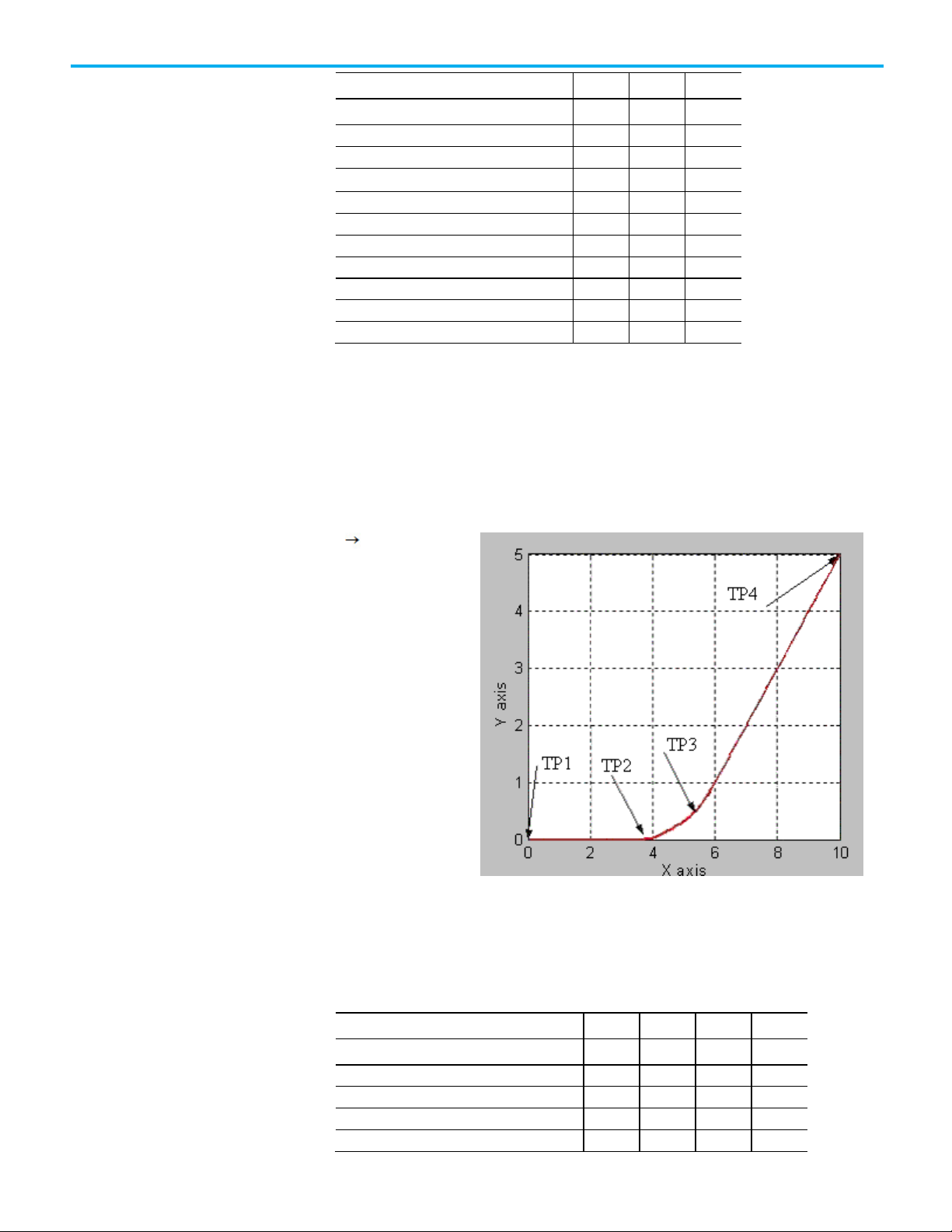
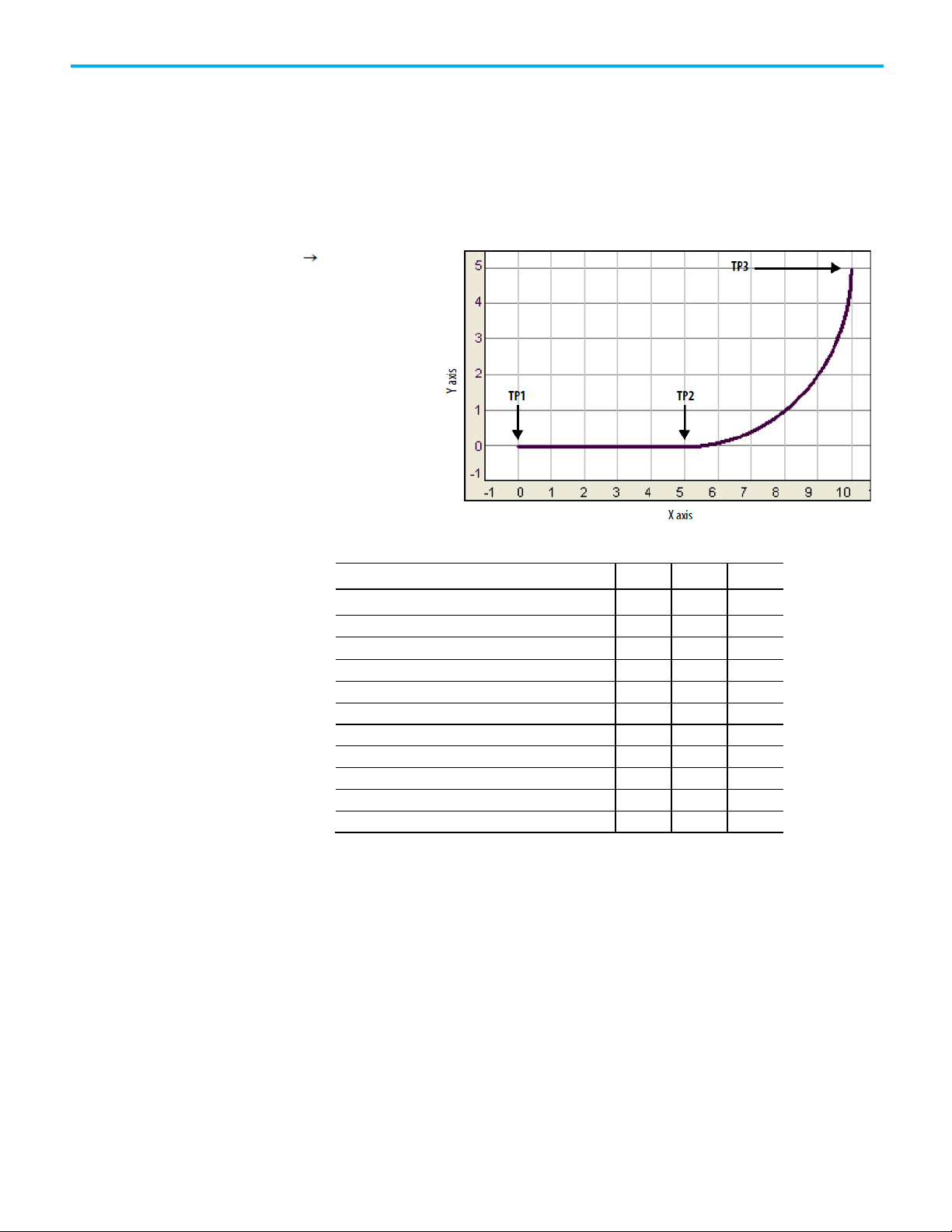
This lists the bit states at transition points of blended move by using no decel.
using no decel
linear linear move
This table shows the bit status at the various transition points shown in the
preceding graph with termination type of No Decel. For No Decel termination
type distance-to-go for transition point TP2 is equal to deceleration distance
for the Move1 instruction. If Move 1 and Move 2 are collinear, then Move1.PC
will be true at TP3, which is the programmed end-point of first move.
20 Rockwell Automation Publication MOTION-UM002G-EN-P - October 2020
Move1.DN T T T T
Move1.AC T F F F
Move1.PC F T T T
Bit
TP1
TP2
TP3
TP4
Move2.AC
F T T F Move2.PC
F F F
T
cs1.MoveTransitionStatus
F T F F cs1.MovePendingStatus
T F F
F
cs1.MovePendingQueueFullStatus
T F F
F
Bit
TP1
TP2
TP3
TP4
Move1.DN
T T T
T
Move1.IP
T F F
F
Move2.DN
T T T T Move2.IP
T T T
F
Move2.AC
F T T F Move2.PC
F F F
T
cs1.MoveTransitionStatus
F T F
F
Bit states at transition
points of blended move by
using command tolerance
linear linear move
Move2.IP T T T F
Chapter 2 Cartesian coordinate system
This lists the bit states at transition points of Blended Move by using
Command Tolerance.
Rockwell Automation Publication MOTION-UM002G-EN-P - October 2020 21
This table shows the bit status at the various transition points shown in the
preceding graph with termination type of Command Tolerance. For
Command Tolerance termination type distance-to-go for transition point TP2
is equal to Command Tolerance for the coordinate system cs1.
Move1.AC T F F F
Move1.PC F T T T
cs1.MovePendingStatus T F F F
cs1.MovePendingQueueFullStatus T F F F
Chapter 2 Cartesian coordinate system
Bit
TP1
TP2
TP3
Move1.AC
T F F
Move1.PC
F T T
Move2.DN
T T T
Move2.IP
T T F
Move2.AC
F T F
Move2.PC
F F T
cs1.MovePendingStatus
T F F
cs1.MovePendingQueueFullStatus
T F F
Bit states at transition
Choose a termination type
points of blended move by
using follow contour
velocity constrained or
unconstrained
linear circular move
This lists the bit states at transition points of blended move by using follow
contour velocity constrained or unconstrained.
This table shows the bits status at the transition points.
Move1.DN T T T
Move1.IP T F F
cs1.MoveTransitionStatus F F F
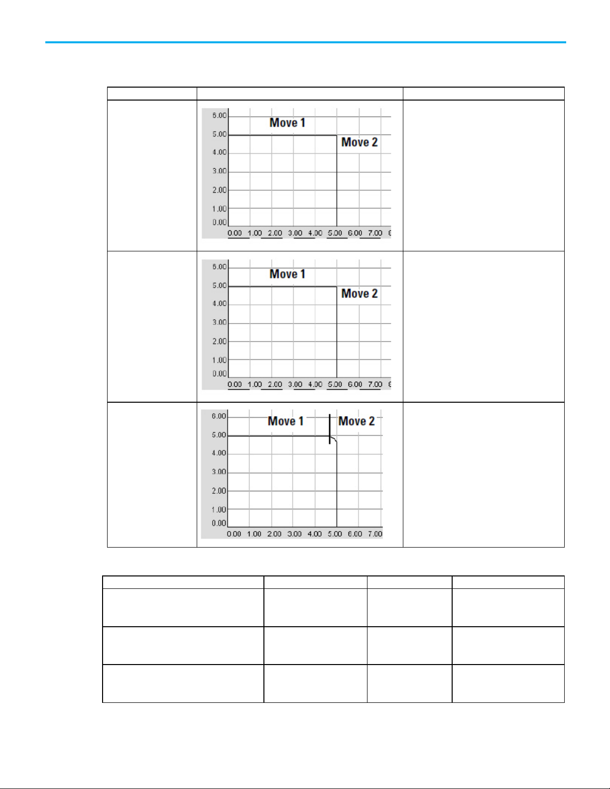
The termination type determines when the instruction is complete. It also
determines how the instruction blends its path into the queued MCLM or
MCCM instruction, if there is one.
22 Rockwell Automation Publication MOTION-UM002G-EN-P - October 2020
If you want the axes to (vector speeds)
And you want the instruction to complete
Then use this Termination
Coordinate System.
position.
coordinate system.
To choose a termination type:
Chapter 2 Cartesian coordinate system
stop between moves.
keep the speed constant except between moves.
transition into or out of a circle without stopping.
when
The following occurs:
• Command position equals target position.
• The vector distance between the target
and actual positions is less than or equal
to the Actual Position Tolerance of the
The command position equals the target
The command position gets within the
Command Position Tolerance of the
The axes get to the point at which they must
decelerate at the deceleration rate.
Type
0 - Actual Tolerance
1 - No Settle
2 - Command Tolerance
3 - No Decel
4 - Follow Contour Velocity
Constrained
accelerate or decelerate across multiple moves.
use a specified Command Tolerance
The command position gets within the
Command Position Tolerance of the
coordinate system.
5 - Follow Contour Velocity
Unconstrained
6 - Command Tolerance
Programmed
Rockwell Automation Publication MOTION-UM002G-EN-P - October 2020 23
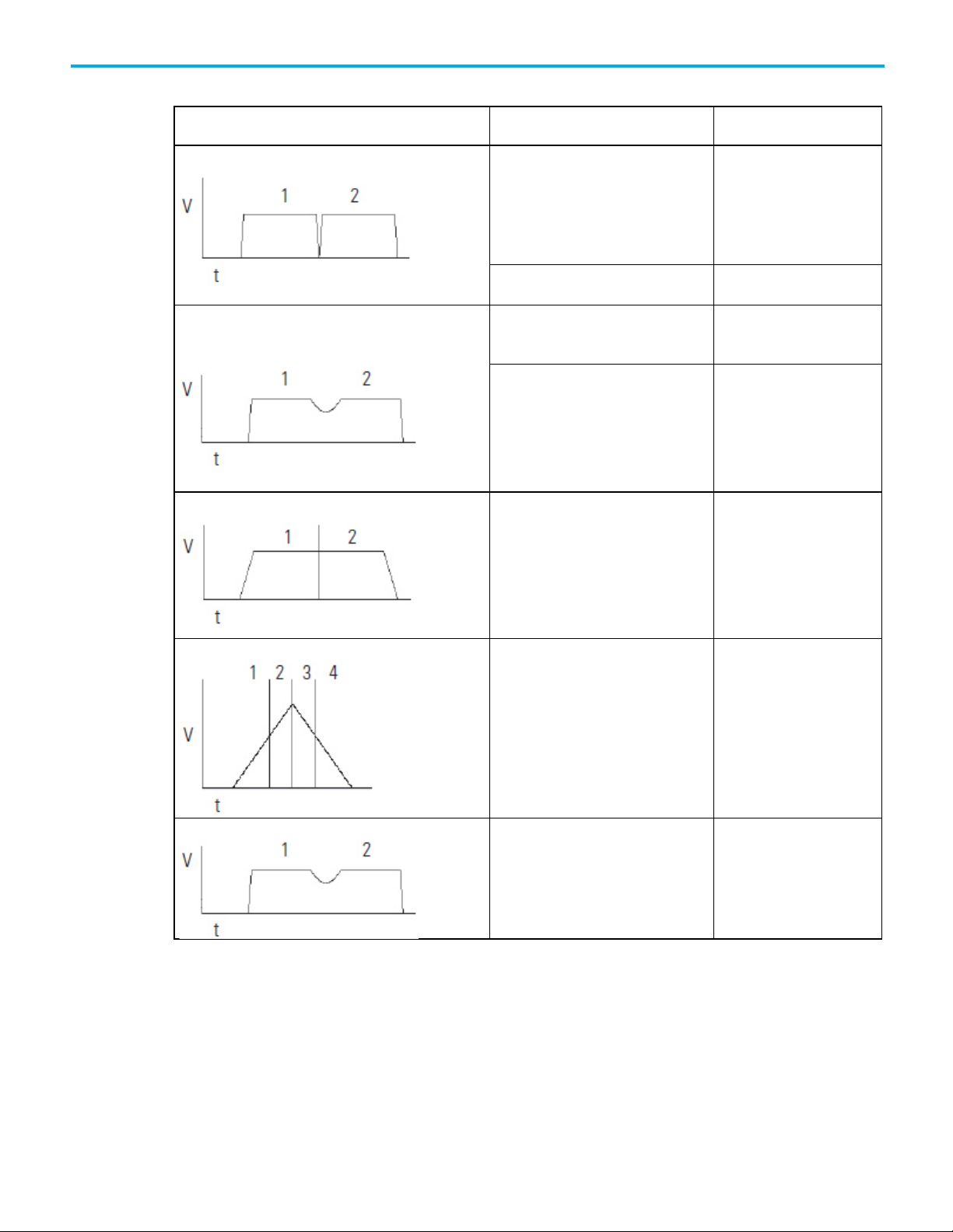
Chapter 2 Cartesian coordinate system
Termination Type
Example Path
Description
Otherwise the instruction stays in process.
The Logix Designer application compares
To the
And uses the
For the
50% of each of the lengths of all other move
configured Command
shorter of the two lengths
command Tolerance length used
To make sure that this is the right choice for you:
• Review the tables below.
0 - Actual Tolerance
1 - No Settle
The instruction stays active until both of these
happen:
• Command position equals target position.
• The vector distance between the target and
actual positions is less than or equal to the
Actual Position Tolerance of the coordinate
system.
At that point, the instruction is complete and a
queued MCLM or MCCM instruction can start.
Important:
Tolerance to a value that your axes can reach.
Make sure that you set the Actual
The instruction stays active until the command
position equals the target position. At that point,
the instruction is complete and a queued MCLM or
MCCM instruction can start.
2, 6 - Command Tolerance
100% of the configured length of the first
instruction using a Command Tolerance
termination type
100% of the configured length of the last move
instruction using a Command Tolerance
termination type
instructions
configured Command
Tolerance for the Coordinate
System
configured Command
Tolerance for the Coordinate
System
Tolerance for the Coordinate
System
The instruction stays active until the command
position gets within the Command Tolerance of
the Coordinate System. At that point, the
instruction is complete and a queued MCLM or
MCCM instruction can start.
If you don’t have a queued MCLM or MCCM
instruction, the axes stop at the target position.
shorter of the two lengths command Tolerance length used
for the first instruction
shorter of the two lengths command Tolerance length used
for the next to last instruction
for each individual instruction
24 Rockwell Automation Publication MOTION-UM002G-EN-P - October 2020
Termination Type
Example Path
Description
Chapter 2 Cartesian coordinate system
3 - No Decel
4 - Follow Contour Velocity
Constrained
5 - Follow Contour Velocity
Unconstrained
The instruction stays active until the axes get to the
deceleration point. At that point, the instruction is
complete and a queued MCLM or MCCM instruction
can start.
• The deceleration point depends on whether you
use a trapezoidal or S-curve profile.
• If you don’t have a queued MCLM or MCCM
instruction, the axes stop at the target position.
The instruction stays active until the axes get to the
target position. At that point, the instruction is
complete and a queued MCLM or MCCM instruction
can start.
• This termination type works best with tangential
transitions. For example, use it to go from a line to
a circle, a circle to a line, or a circle to a circle.
• The axes follow the path.
• The length of the move determines the maximum
speed of the axes. If the moves are long enough,
the axes will not decelerate between moves. If the
moves are too short, the axes decelerate between
moves.
This termination type is similar to the contour
velocity constrained. It has these differences:
• Use this termination type to get a triangular
velocity profile across several moves. This reduces
jerk.
• To avoid position overshoot at the end of the last
move, you must calculate the deceleration speed at
each transition point during the deceleration-half
of the profile.
• You must also calculate the starting speed for each
move in the deceleration half of the profile.
Important Considerations
If you stop a move (that is, using an MCS or by changing the speed to zero
with an MCCD) during a blend and then resume the move (that is, by
reprogramming the move or by using an another MCCD), it will deviate from
the path that you would have seen if the move had not been stopped and
resumed. The same phenomenon can occur if the move is within the decel
point of the start of the blend. In either case, the deviation will most likely be a
slight deviation.
Rockwell Automation Publication MOTION-UM002G-EN-P - October 2020 25
Chapter 2 Cartesian coordinate system
Velocity Profiles for Collinear Moves
Collinear moves are those that lie on the same line in space. Their direction
can be the same or opposite. The velocity profiles for collinear moves can be
complex. This section provides you with examples and illustrations to help
you understand the velocity profiles for collinear moves programmed with
MCLM instructions.
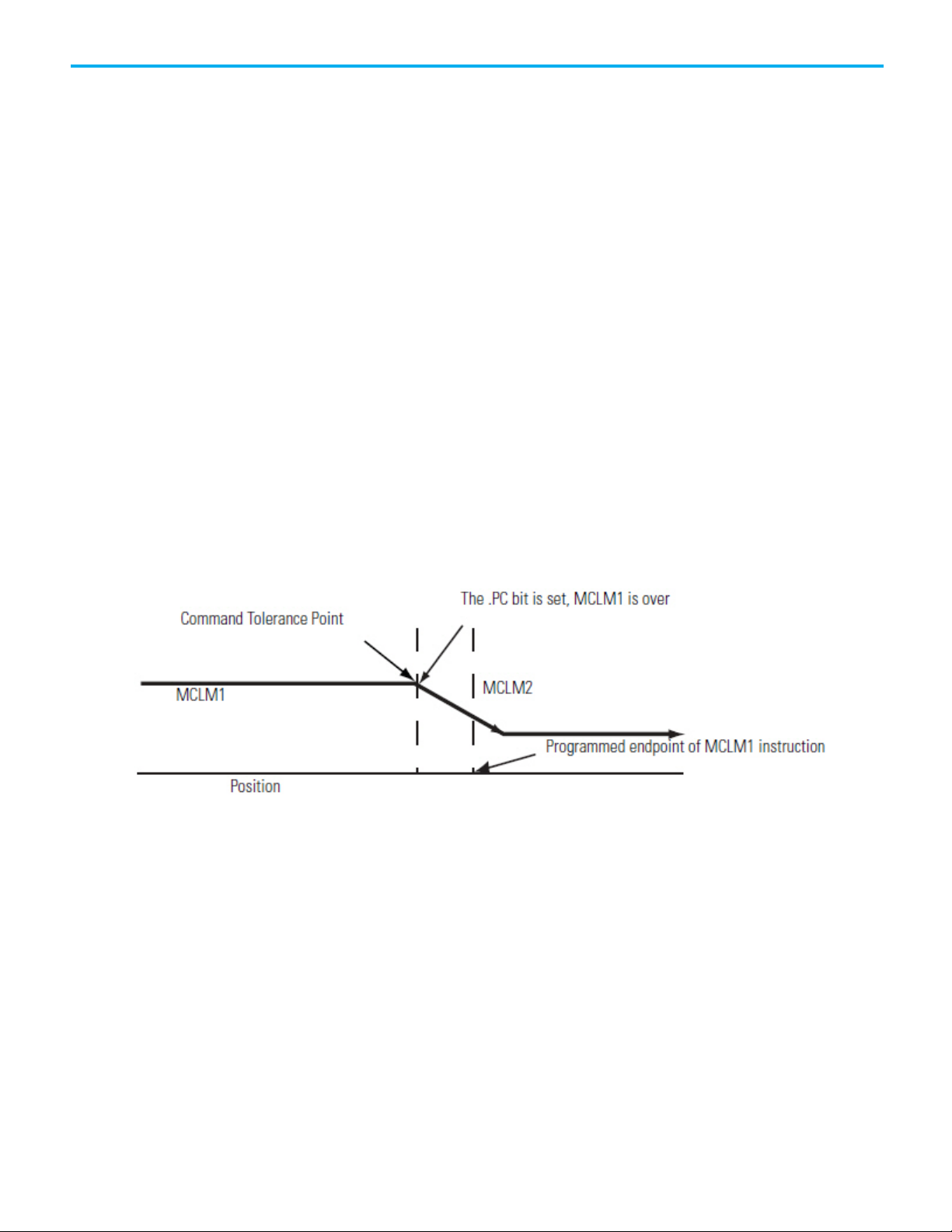
Velocity Profiles for Collinear Moves with Termination Type 2 or 6
This illustration shows the velocity profile of two collinear moves using a
Command Tolerance (2) termination type. The second MCLM instruction has
a lower velocity than the first MCLM instruction. When the first MCLM
instruction reaches its Command Tolerance point, the move is over and the
.PC bit is set.
Velocity Profile of Two Collinear Moves When the Second Move has a
Lower Velocity than the First Move and Termination Type 2 or 6 is
Used
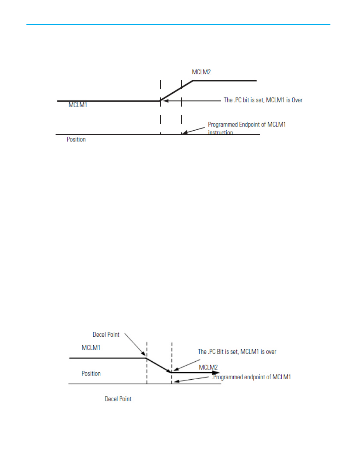
This illustration shows the velocity profile of two collinear moves using a
Command Tolerance (2) termination type. The second MCLM instruction has
a higher velocity than the first MCLM instruction. When the first MCLM
instruction reaches its Command Tolerance point, the move is over and the
.PC bit is set.
26 Rockwell Automation Publication MOTION-UM002G-EN-P - October 2020
Chapter 2 Cartesian coordinate system
Velocity Profile of Two Collinear Moves When the Second Move has a
Higher Velocity than the First Move and Termination Type 2 or 6 is
Used
Velocity Profiles for Collinear Moves with Termination Types 3, 4, or
5
This illustration shows a velocity profile of two collinear moves. The second
MCLM instruction has a lower velocity than the first MCLM instruction and
one of these termination types are used:
• No Decel (3)
• Follow Contour Velocity Constrained (4)
• Follow Contour Velocity Unconstrained (5)
When the first MCLM instruction reaches the deceleration point, it
decelerates to the programmed velocity of the second move. The first move is
over and the .PC bit is set.
Velocity Profile of Two Collinear Moves When the Second Move has a
Lower Velocity than the First Move and Termination Type 3, 4, or 5 is
Used
Rockwell Automation Publication MOTION-UM002G-EN-P - October 2020 27
Chapter 2 Cartesian coordinate system
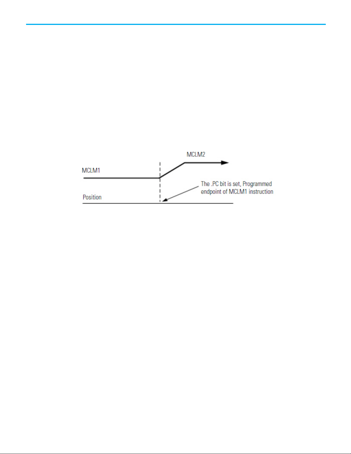
This illustration shows a velocity profile of two collinear moves. The second
MCLM instruction has a higher velocity than the first MCLM instruction and
one of these termination types are used:
• No Decel (3)
• Follow Contour Velocity Constrained (4)
• Follow Contour Velocity Unconstrained (5)
The .PC bit is set when the first move reaches its programmed endpoint.
Velocity Profile of Two Collinear Moves When the Second Move has a
Higher Velocity than the First Move and Termination Type 3, 4, or 5 is
Used
Symmetric Profiles
Profile paths are symmetric for all motion profiles.
Programming the velocity, acceleration, and deceleration values
symmetrically in the forward and reverse directions generates the same path
from point A to point C in the forward direction, as from point C to point A in
the reverse direction.
While this concept is most easily shown in a two-instruction sequence, it
applies to instruction sequences of any length provided that they are
programmed symmetrically.
28 Rockwell Automation Publication MOTION-UM002G-EN-P - October 2020

IMPORTANT
Chapter 2 Cartesian coordinate system
Refer to this Example of a Symmetric Profile for more details.
We recommend that you terminate any sequence of moves by either Termination
Type 0 or 1, that is, TT0 or TT1.
To guarantee that your trajectory is symmetric, you must terminate any
sequence of moves by either Termination Types 0 or 1. You should also use a
Termination Type of 0 or 1 at the Reversal Point of a profile that moves back
on itself.
Using a TT2, TT3, TT4, TT5, ot TT6 as the last move in a profile (or the reversal
point) is safe. However, the resulting trajectory from A to B may not always be
the same as that from B to A. Explicit termination of the sequence of moves
helps the controller to optimize the velocity profile, reduce the CPU load, and
guarantee a symmetric profile.
Rockwell Automation Publication MOTION-UM002G-EN-P - October 2020 29

Chapter 2 Cartesian coordinate system
Termination Types 2, 3, 4, or 6
speed that causes them to overshoot the target position during deceleration.
How To Get a Triangular Velocity Profile
If you want to program a pick and place action in four moves, minimize the
Jerk rate, and use a triangular velocity profile.
Then, use termination type 5. The other termination types may not let you get
to the speed you want.
The length of each move determines its maximum speed. As a result, the axes will not reach a
30 Rockwell Automation Publication MOTION-UM002G-EN-P - October 2020

Termination Type 5
If the next
move is
And the Termination Type of the first
move is
Then
Chapter 2 Cartesian coordinate system
The axes accelerate to the speed that you want. You must calculate the starting speed for each
move in the deceleration-half of the profile.
Slower 2 - Command Tolerance
3 - No Decel
4 - Contour Velocity Constrained
5 - Contour Velocity Unconstrained
6 - Command Tolerance Programmed
Blending Moves at Different Speeds
You can blend MCLM and MCCM instructions where the vector speed of the
second instruction is different from the vector speed of the first instruction.
Rockwell Automation Publication MOTION-UM002G-EN-P - October 2020 31

Chapter 2 Cartesian coordinate system
Faster 2 - Command Tolerance
3 - No Decel
6 - Command Tolerance Programmed
4 - Contour Velocity Constrained
5 - Contour Velocity Unconstrained
32 Rockwell Automation Publication MOTION-UM002G-EN-P - October 2020

death to personnel.
Establish reference frame
Chapter 3
Cartesian coordinate system examples
Configure an Articulated Independent robot
Use these guidelines when configuring an Articulated Independent robot.
WARNING: Before turning ON the Transform and/or establishing the reference frame, be sure
to do the following for the joints of the target coordinate system.
• Set and enable the soft travel limits.
• Enable the hard travel limits.
Failure to do this can allow the robot to move outside of the work envelope causing machine
damage and/or serious injury or death to personnel.
for an articulated
independent robot
See also
Establish reference frame for an Articulated Independent robot
on page 33
Methods to establish a reference frame for Articulated Independent
robot on page 35
Work envelope for Articulated Independent robot on page 60
Define configuration parameters for Articulated Independent robot
on page 37
The reference frame is the Cartesian coordinate frame that defines the origin
and the three primary axes (X1, X2, and X3). These axes measure the real
Cartesian positions.
WARNING:
the robotic arm to move to unexpected positions causing machine damage and/or injury or
Failure to properly establish the correct reference frame for your robot can cause
Rockwell Automation Publication MOTION-UM002G-EN-P - October 2020 33
The reference frame for an Articulated Independent robot is located at the
base of the robot as shown in this figure.

Chapter 3 Cartesian coordinate system examples
Illustration 1
Before establishing the Joint-to-Cartesian reference frame relationship, it is
important to know some information about the Kinematic mathematical
equations used in the Logix controllers. The equations are written as if the
Articulated Independent robot joints are positioned as shown in the following
illustration.
Illustration 2 - Side view
• +J1 is measured counterclockwise around the +X3 axis starting at an
angle of J1=0 when L1 and L2 are both in the X1-X2 plane.
• +J2 is measured counterclockwise starting with J2=0 when L1 is parallel
to X1-X2 plane.
• +J3 is measured counterclockwise with J3=0 when L2 is aligned with
link L1.
When the robot is physically in this position, the Logix Designer application
Actual Position tags for the axes must be:
• J1 = 0.
• J2 = 0.
• J3 = 0.
34 Rockwell Automation Publication MOTION-UM002G-EN-P - October 2020

For each:
Use one of these methods to establish the reference frame:
Illustration 3 - Side view
Chapter 3 Cartesian coordinate system examples
When the robot is physically in the above position, the Logix Designer
application Actual Position tags for the axes must be:
• J1 = 0.
• J2 = 90.
• J3 = -90.
If the physical position and joint angle values of the robot cannot match those
shown in the preceding illustrations, use one of the Alternate Methods for
Establishing the Joint-to-Cartesian reference frame relationship.
Methods to establish a reference frame for an articulated independent robot
See also
Methods for establishing a reference frame for an articulated
independent robot on page 35
Use the following methods to establish a reference frame for the robot.
Incremental axis Each time the power for the robot is cycled.
Absolute axis Only to establish absolute home.
• Method 1 - Establishes a Zero Angle Orientation and allows the
configured travel limits and home position on the joint axes to remain
operational. Use this method when operating the axes between the
travel limits determined prior to programming a Motion Redefine
Position (MRP) instruction and want these travel limits to stay
operational.
• Method 2 - Uses a MRP instruction to redefine the axes position to
align with the joint reference frame. This method may require the soft
travel limits to be adjusted to the new reference frame.
Rockwell Automation Publication MOTION-UM002G-EN-P - October 2020 35
See also
Method 1 for an incremental axis on page 59

Chapter 3 Cartesian coordinate system examples
If the Logix Designer application read-out values
Set the Zero Angle Orientations on the
J3 = 5
Z3 = -5
Method 1 - Establish a
Method 2 - Establish a
Each axis for the robot has the mechanical hard stop in each of the positive
and negative directions. Manually move or press each axes of the robot
reference frame
against its associated mechanical hard stop and redefine it to the hard limit
actual position provided by the robot manufacturer. J1 is the axis at the base
of the robot that rotates around X3.
When the robot is moved so that Link1 is parallel to the X3 axis and Link2 is
parallel to X1 axis as shown in Articulated Dependent 3, the Logix Designer
application values for the Actual Position tags should be:
• J1 = 0.
• J2 = 90 .
• J3 = 0 .
If the Logix Designer application Actual Position tags do not show these
values, configure the Zero Angle Orientation for the joint or joints that do not
correspond.
Method 2 for an absolute axis on page 36
are:
J1 = 10
J2 = 80
Setting the Zero Angle Orientations
Coordinate System Properties dialog box to:
Z1 = -10
Z2 = 10
reference frame using a
MRP instruction
36 Rockwell Automation Publication MOTION-UM002G-EN-P - October 2020
Position the robot so that:
• L1 is parallel to the X3 axis.
• L2 is parallel to X1 axis.

IMPORTANT
measurement units.
Chapter 3 Cartesian coordinate system examples
Program a Motion Redefine Position (MRP) instruction for all three axes with
the following values:
• J1 = 0
• J2 = 90°
• J3 = -90°
The Joint-to-Cartesian reference frame relationship is automatically
established by the Logix controller after the Joint coordinate system
parameters, which are the link lengths, base offsets, and end-effector offsets,
are configured and the MCT instruction is enabled.
See also
Method 1 - Establish a reference frame using zero angle orientation
on page 35
Configuration parameters for Articulated Independent robot
Configure the Logix Designer application to control robots with varying reach
and payload capacities. The configuration parameter values for the robot
include:
• Link lengths
• Base offset
• End effector offsets
The configuration parameter information is available from the robot
manufacturer.
Verify that the values for the Link Lengths, Base Offsets, and End-Effector Offsets
are entered in the Coordinate System Properties dialog box using the same
This example illustrates the typical configuration parameters for an
Articulated Independent robot.
Rockwell Automation Publication MOTION-UM002G-EN-P - October 2020 37

Chapter 3 Cartesian coordinate system examples
For an articulated independent robot
The length of
Is equal to the value of the distance between
Link lengths for Articulated
If the robot is two-dimensional, then X3b and X3e are X2b and X2e.
See also
Link lengths for Articulated Independent robot on page 38
Base offsets for Articulated Independent robot on page 62
End effector offsets for Articulated Independent robot on page 39
Link lengths are the rigid mechanical bodies attached at joints.
Independent robot
with
2 dimensions L1
L2
3 dimensions L1
L2
J1 and J2
J2 and the end-effector
J2 and J3
J3 and the end-effector
Enter the link lengths on the Geometry tab in the Coordinate System
Properties dialog box.
38 Rockwell Automation Publication MOTION-UM002G-EN-P - October 2020
See also
Base offset for Articulated Independent robot on page 62
End effector offsets for Articulated Independent robot on page 39

Type the Base Offset values.
Base Offsets
End-Effector Offsets for
For the robot shown in our
example, the Base Offset values
are:
• X1b = 3.0
• X3b = 4.0
Chapter 3 Cartesian coordinate system examples
Configuration parameters for Articulated Independent robot on page
37
The Base Offset is a set of coordinate values that redefines the origin of the
robot. The correct base offset values are typically available from the robot
manufacturer. Type the values for the base offsets in the X1b and X3b boxes of
the Coordinate System Properties dialog box.
Figure 59 - Example of Base Offsets for an Articulated Independent robot
Articulated Independent
robot
The robot can have an end effector attached to the end of robot link L2. If
there is an attached end effector, configure the End-Effector Offset value on
the Offsets tab in the Coordinate System Properties dialog box. The EndEffector Offsets are defined with respect to the tool reference frame at the
tool tip.
Some robots also have an offset defined for the J3 joint. Account for this value
when computing the X3e end effector offset value. If the value for X3e offset is
Rockwell Automation Publication MOTION-UM002G-EN-P - October 2020 39

Chapter 3 Cartesian coordinate system examples
Configure Delta robot
entered as the sum of X3e1+X3e2 (-3+1.5 = -1.5), the configured value for X3e
is -1.5.
geometries
See also
Configuration parameters for Articulated Independent robot on page
37
Link Lengths for Articulated Independent robot on page 38
Base Offsets for Articulated Independent robot on page 62
The Logix Designer application supports three types of geometries that are
often called parallel manipulators.
• Three-dimensional Delta
• Two-dimensional Delta
• SCARA Delta
In these geometries, the number of joints is greater than the degrees of
freedom, and not all the joints are actuated (motor driven). These un-actuated
joints are typically spherical joints.
40 Rockwell Automation Publication MOTION-UM002G-EN-P - October 2020

Configure a Delta Three-
dimensional robot
Chapter 3 Cartesian coordinate system examples
This illustration shows a four axes Delta robot that moves in threedimensional Cartesian (X1, X2, X3) space. This type of robot is often called a
spider or umbrella robot.
The Delta robot in this illustration is a three-degree of freedom robot with an
optional fourth degree of freedom used to rotate a part at the tool tip. In the
Logix Designer application, the first three-degrees of freedom are configured
as three joint axes (J1, J2, J3) in the robots coordinate system. The three joint
axes are:
• Directly programmed in joint space.
• Automatically controlled by the embedded Kinematics software in the
Logix Designer application from instructions programmed in a virtual
Cartesian coordinate system.
This robot contains a fixed top plate and a moving bottom plate. The fixed top
plate is attached to the moving bottom plate by three link-arm assemblies. All
three of the link-arm assemblies have a single top link arm (L1) and a
parallelogram two-bar link assembly (L2).
As each axis (J1, J2, J3) is rotated, the TCP of the gripper moves
correspondingly in (X1, X2, X3) direction. The gripper remains vertical along
the X3 axis while its position is translated to (X1, X2, X3) space by the
mechanical action of the parallelograms in each of the forearm assemblies.
The mechanical connections of the parallelograms via spherical joints ensures
that the top and bottom plates remain parallel to each other.
Program the TCP to an (X1, X2, X3) coordinate, then the Logix Designer
application computes the commands necessary for each of the joints (J1, J2 ,J3)
to move the gripper linearly from the current (X1, X2, X3) position to the
programmed (X1, X2, X3) position, at the programmed vector dynamics.
Rockwell Automation Publication MOTION-UM002G-EN-P - October 2020 41
When each top link (L1) moves downward, its corresponding joint axis (J1, J2,
or J3) is assumed to be rotating in the positive direction. The three joint axes
of the robot are configured as linear axes.
To rotate the gripper, configure a fourth axis as a linear or rotary,
independent axis.

Chapter 3 Cartesian coordinate system examples
Calibrate a Delta Three-
See also
Establish the reference frame for a Delta Three-dimensional robot
on page 42
Calibrate a Delta Three-dimensional robot on page 42
Configure Zero Angle Orientation for Delta Three-dimensional robot
on page 43
Identify the Work Envelope for Delta Three-dimensional robot on page
44
Define Configuration Parameters for Delta Three-dimensional robot
on page 45
Establish the reference
frame for a Delta Threedimensional robot
The reference frame for the Delta geometries is located at the center of the
top fixed plate. Joint 1, Joint 2, and Joint 3 are actuated joints. If the Delta
coordinate system in the Logix Designer application is configured with the
joints homed at 0 in the horizontal position, then L1 of one of the link pairs
will be aligned along the X1 positive axis as shown. Moving in the counterclockwise direction from Joint 1 to Joint 2, the X2 axis will be orthogonal to the
X1 axis. Based on the right hand rule, X3 positive will be the axis pointing up
(out of the paper).
dimensional robot
42 Rockwell Automation Publication MOTION-UM002G-EN-P - October 2020
See also
Calibrate a Delta Three-dimensional robot on page 42
Use these steps to calibrate the robot.
To calibrate a Delta Three-dimensional robot:
1. Obtain the angle values from the robot manufacturer for J1, J2, and J3
at the calibration position. Use these values to establish the referenc
p
osition.
e

Alternate method for
Configure Zero Angle
2. Move all joints to the calibration position by jogging the robot under
programmed control or manually moving the robot when the joint
axes are in an open loop state.
3. Do one of the following:
a. Use the Motion Redefine Position (MRP) instruction to set the
positions of the joint axes to the calibration values obtained in step
1.
b. Set the configuration value for the joint axes home position to the
calibration values obtained in step 1 and execute a Motion Axis
Home (MAH) instruction for each joint axis.
4. Move each joint to an absolute position of 0.0. Verify that each joint
position reads 0 degrees and the respective L1 is in a horizontal
position.
If L1 is not in a horizontal position, see the alternate method for
calibrating a Delta three-dimensional robot.
Chapter 3 Cartesian coordinate system examples
calibrating a Delta Threedimensional robot
Orientations for Delta
Three-dimensional robot
See also
Alternate method for calibrating a Delta Three-dimensional robot
on page 43
Rotate each joint to a position so that the respective link is at a horizontal
position. Perform one of the following:
• Use an MRP instruction to set all the joint angles to 0 at this
position.
• Configure the values for the Zero Angle Offsets on the Geometry tab in
the Coordinate System Properties dialog box equal to the values of the
joints in a horizontal position.
For Delta robot geometries, the internal transformation equations in the
Logix Designer application are written assuming that:
• Joints are at 0 when link L1 is horizontal.
• As each top link (L1) moves downward, its corresponding joint axis (J1,
J2, or J3) is rotating in the positive direction.
Rockwell Automation Publication MOTION-UM002G-EN-P - October 2020 43
If you want the joint angular position when L1 is horizontal to be at any other
value than 0 , then configure the zero angle orientation values on
the Geometry tab on Coordinate System Properties dialog box to align the
joint angle positions with the internal equations.
For example, if the Delta robot is mounted so that the joints attached at the
top plate are homed at 30 in the positive direction below horizontal and you

Chapter 3 Cartesian coordinate system examples
Identify the work envelope
want the Logix Designer application readout values to be zero in this position,
then configure the Zero Angle Orientation values to -30 on the Geometry
tab on the Coordinate System Properties dialog box.
Delta Robot with Joints Homed at 30
Configuring Delta robot Zero Angle orientation
for a Delta Threedimensional robot
44 Rockwell Automation Publication MOTION-UM002G-EN-P - October 2020
The work envelope is the three-dimensional region of space that defines the
reaching boundaries for the robot arm. The typical work envelope for a Delta
robot looks similar to plane in the upper region, with sides similar to a
hexagonal prism and the lower portion similar to a sphere. For more
information regarding the work envelope of Delta three-dimensional robots,
see the documentation provided by the robot manufacturer.
Program the robot within a rectangular solid defined inside the robot's work
zone. The rectangular solid is defined by the positive and negative dimensions

Define configuration
Chapter 3 Cartesian coordinate system examples
of the X1, X2, X3 virtual source axes. Be sure that the robot position does not
go outside the rectangular solid. Check the position in the event task.
To avoid issues with singularity positions, the MCT instruction internally
calculates the joint limits for the Delta robot geometries. When an MCT
instruction is invoked for the first time, the maximum positive and maximum
negative joint limits are internally calculated based upon the link lengths and
offset values entered on the Geometry and Offsets tabs in the Coordinate
System Properties dialog box.
Delta three-dimensional Configuration Systems Properties dialog box
- Geometry and Offsets tabs
parameters for a Delta
Three-dimensional robot
Rockwell Automation Publication MOTION-UM002G-EN-P - October 2020 45
During each scan, the joint positions in the forward and inverse kinematics
routines are checked to ensure that they are within the maximum and
minimum negative joint limits.
Homing or moving a joint axis to a position beyond a computed joint limit
and invoking a MCT instruction results in an error 67 (Invalid Transform
position). For more information regarding error codes, see
Logix 5000
Controllers Motion Instructions Reference Manual, publication MOTIONRM002.
Configure the Logix Designer application to control robots with varying reach
and payload capacities. The configuration parameter values for the robot
include:
• Link lengths
• Base offsets
• End-effector offsets
The configuration parameter information is available from the robot
manufacturer.

Chapter 3 Cartesian coordinate system examples
IMPORTANT
measurement units.
Configure a Delta Two-
This illustration shows a two-dimensional Delta robot that moves in two-
dimensional robot
dimensional Cartesian space.
This robot has two rotary joints that move the gripper in the (X1, X2) plane.
Two forearm assemblies attach a fixed top plate to a movable bottom plate. A
gripper is attached to the movable bottom plate. The bottom plate is always
orthogonal to the X2 axis and its position is translated in Cartesian space (X1,
X2) by mechanical parallelograms in each forearm assembly. The two joints,
J1, and J2, are actuated joints. The joints between links L1 and L2 and between
L2 and the base plate are unactuated joints.
Verify that the values for the Link Lengths, Base Offsets, and End-Effector Offsets
are entered in the Coordinate System Properties dialog box using the same
Each joint is rotated independently to move the gripper to a programmed (X1,
X2) position. As each joint axis (J1 or J2 or J1 and J2) is rotated, the TCP of the
gripper moves correspondingly in the X1 or X2 direction or X1 and X2
direction. Program the TCP to a (X1, X2) coordinate, then the Logix Designer
application uses internal vector dynamic calculations to compute the proper
commands needed for each joint to move the gripper linearly from the current
(X1, X2) position to the programmed (X1, X2) position.
The two joint axes (J1 and J2) of the robot are configured as linear axes.
To rotate the gripper, configure a third axis as a linear or rotary, independent
axis.
See also
Establish the reference frame for a Delta Two-dimensional robot
on page 47
Calibrate a Delta Two-dimensional robot on page 47
Identify the work envelope for a Delta Two-dimensional robot on page
47
46 Rockwell Automation Publication MOTION-UM002G-EN-P - October 2020

Establish the reference
frame for a Delta Two-
Calibrate a Delta Two-
dimensional robot
Define configuration parameters for a Delta Two-dimensional robot
on page 48
The reference frame for the two-dimensional Delta geometry is located at the
center of the fixed top plate. When the angles of joints J1 and J2 are both at 0
, each of the two L1 links is along the X1 axis. One L1 link is pointing in the
positive X1 direction, the other in the negative X1 direction.
When the right-hand link L1 moves downward, joint J1 is assumed to be
rotating in the positive direction and when L1 moves upward, the J1 is
assumed to be moving in the negative direction. When the left-hand link L1
moves downward, joint J2 is assumed to be rotating in the positive direction
and when left-hand L1 moves upward, the J2 is assumed to be moving in the
negative direction.
Chapter 3 Cartesian coordinate system examples
dimensional robot
See also
Calibrate a Delta Two-dimensional robot on page 47
Calibrate a Delta two-dimensional robot using the same method for
calibrating a Delta three-dimensional robot. Obtain the angle values from the
robot manufacturer for J1 and J2 at the calibration position. Use these values
to establish the reference position.
See also
Calibrate a Delta Three-dimensional robot on page 42
Rockwell Automation Publication MOTION-UM002G-EN-P - October 2020 47

Chapter 3 Cartesian coordinate system examples
Identify the work envelope
Define configuration
for a Delta Two-
The work envelope is the two-dimensional region of space that defines the
reaching boundaries for the robot arm. The typical working envelope for a
two-dimensional Delta robot is a boundary composed of circular arcs.
Dimensional robot
Program the parameters for the two-dimensional Delta robot within a
rectangle, dotted lines in the illustration, inside the robots work zone. Define
the rectangle by the positive and negative dimensions of the X1, X2 virtual
source axes. Be sure that the robot position does not go outside the rectangle.
Check the position in the event task.
parameters for a Delta
Two-dimensional robot
To avoid problems with singularity positions, the Logix Designer application
internally calculates the joint limits for the Delta robot geometries. When an
MCT instruction is invoked for the first time, the maximum positive and
maximum negative joint limits are internally calculated based upon the link
lengths and offset values entered on the Geometry and Offsets tabs of
the Coordinate System Properties dialog box.
For more information about maximum positive and negative joint limits, see
Maximum positive joint limit condition and Maximum negative joint limit
condition.
Homing or moving a joint axis to a position beyond a computed joint limit
and then invoking an MCT instruction, results in an error 67 (Invalid
Transform position). For more information regarding error codes see
the Logix 5000 Controllers Motion Instructions Reference Manual
publication MOTION-RM002.
Configure the Logix Designer application to control robots with varying reach
and payload capacities. The configuration parameter values for the robot
include:
• Link lengths
• Base offsets
• End-effector offsets
,
48 Rockwell Automation Publication MOTION-UM002G-EN-P - October 2020
The configuration parameter information is available from the robot
manufacturer.

IMPORTANT
measurement units.
Configure a SCARA Delta
robot
Establish the reference
Verify that the values for the Link Lengths, Base Offsets, and End-Effector Offsets
are entered in the Coordinate System Properties dialog box using the same
Chapter 3 Cartesian coordinate system examples
The SCARA Delta robot geometry is similar to a two-dimensional Delta robot
geometry except that the X1-X2 plane is tilted horizontally with the third
linear axis in the vertical direction (X3).
See also
frame for a SCARA Delta
robot
Establish the reference frame for a SCARA Delta robot on page 49
Calibrate a SCARA Delta robot on page 50
Identify the work envelope for a SCARA Delta robot on page 50
Define configuration parameters for a SCARA Delta robot on page 51
Configure a Delta robot with a Negative X1b offset on page 51
The reference frame for the SCARA Delta robot is located at the center of the
base plate.
When the angles of joints J1 and J2 are both at 0 , the two L1 links is along the
X1 axis. One L1 link is pointing in the positive X1 direction, the other in the
negative X1 direction.
When the right-hand link L1 moves in the clockwise direction (looking down
on the robot), joint J1 is assumed to be rotating in the positive direction. When
the right-hand link L1 moves counterclockwise, joint J1 is assumed to be
moving in the negative direction.
When left-hand link L1 moves in the clockwise direction, joint J2 is assumed to
be moving in the negative direction. When the left-hand link L1 moves in the
counterclockwise direction, joint J2 is assumed to be rotating in the positive
direction.
Rockwell Automation Publication MOTION-UM002G-EN-P - October 2020 49
Based on the right hand rule, X3 positive will be orthogonal to the X1-X2 plane
pointing up. The linear axis will always move in the X3 direction.
When configuring a SCARA Delta robot in the Logix Designer application,
observe these guidelines:

Chapter 3 Cartesian coordinate system examples
Calibrate a SCARA Delta
Identify the work envelope
• Configure the source and the target coordinate system with a
• The linear axis configured as a third axis must be the same for both the
transform dimension of two.
source and target coordinate systems.
robot
for a SCARA Delta robot
Calibrate a SCARA Delta robot using the same method for calibrating a Delta
three-dimensional robot. For more information about calibration, see
Calibrate a Delta Three-dimensional Robot.
See also
Calibrate a Delta Three-dimensional Robot on page 42
The work envelope for a SCARA Delta robot is similar to the two-dimensional
Delta robot in the X1-X2 plane. The third linear axis extends the work region
making it a solid region. The maximum positive and negative limits of the
linear axis defines the height of the solid region.
It is recommended to program the SCARA Delta robot within a rectangular
solid defined inside the work zone of the robot. Define the rectangular solid
by the positive and negative dimensions of the X1, X2, X3 virtual source axes.
Be sure that the robot position does not go outside the rectangular solid.
Check the position in the event task.
50 Rockwell Automation Publication MOTION-UM002G-EN-P - October 2020
To avoid problems with singularity positions, the Logix Designer application
internally calculates the joint limits for the Delta robot geometries. For more
information about maximum positive and negative joint limits, see Maximum
positive joint limit condition and Maximum negative joint limit condition.
Homing or moving a joint axis to a position beyond a computed joint limit,
and invoking an MCT instruction, results in an error 67 Invalid Transform
position. For more information regarding error codes, see
Logix 5000

IMPORTANT
measurement units.
Define configuration
parameters for a SCARA
Configure a Delta robot with
Controllers Motion Instructions Reference Manual, publication MOTIONRM002.
Chapter 3 Cartesian coordinate system examples
See also
Maximum positive joint limit condition
Maximum negative joint limit condition
The Logix Designer application can be configured for control of robots with
varying reach and payload capacities. The configuration parameter values for
the robot include:
Delta robot
a Negative X1b offset
• Link lengths
• Base offset
• End-effector offset
The configuration parameter information is available from the robot
manufacturer.
Verify that the values for the Link Lengths, Base Offsets, and End-Effector Offsets
are entered in the Coordinate System Properties dialog box using the same
See also
Link length for SCARA Delta robot
Base Offset for SCARA Delta robot
End Effector Offset for SCARA Delta robot
Beginning with version 17 of the application, you can use negative offsets for
the X1b base offset on 2D and 3D delta geometries. For example, a mechanical
2D delta robot using a negative X1b offset has a mechanical configuration as
shown in the diagram.
Rockwell Automation Publication MOTION-UM002G-EN-P - October 2020 51

Chapter 3 Cartesian coordinate system examples
Arm solutions
The base offset X1b is the value equal to the distance from the origin of the
robot coordinate system to one of the actuator joints. In the previous figure,
one of the actuator joints (P1), is on the negative side of X1. The base offset X1b
is -10 units from the origin of the coordinate system (X1 - X2 intersection) to
P1.
The Logix Designer application coordinate system configuration for the offset
tab used with the preceding example is shown in the following example.
This negative offset description also applies for Delta 3D and SCARA-Delta
configurations.
A kinematic arm solution is the position of all joints on the robot that
correspond to a Cartesian position. When the Cartesian position is inside the
workspace of the robot, then at least one solution always exists. Many of the
geometries have multiple joint solutions for a single Cartesian position.
• Two axis robots - two joint solutions typically exist for a Cartesian
position.
• Three axis robots - four joint solutions typically exist for a Cartesian
position.
See also
Left-arm and right-arm solutions for two-axes robots on page 53
Solution mirroring for three-dimensional robots on page 53
Change the robot arm solution on page 54
52 Rockwell Automation Publication MOTION-UM002G-EN-P - October 2020
Plan for singularity on page 55
Encounter a no-solution position on page 55

Right-arm
Right-arm mirror
Left-arm and right-arm
solutions for two-axes
Solution mirroring for
robots
Chapter 3 Cartesian coordinate system examples
A robot having an arm configuration has two kinematics solutions when
attempting to reach a given position. Point A is shown in the following
illustration. One solution satisfies the equations for a right-armed robot, the
other solution satisfies the equations for a left-armed robot.
See also
three-dimensional robots
Arm solutions on page 52
For a three-dimensional Articulated Independent robot, there are four
solutions for the same point:
• Left-arm
• Right-arm
• Left-arm mirror
• Right-arm mirror
For example, consider the Cartesian point XYZ (10,0,15). The joint position
corresponding to this point has four joint solutions. Two of the solutions are
the same as the solutions for the two-dimensional case. The other solutions
are mirror image solutions where J1 is rotated 180 .
Rockwell Automation Publication MOTION-UM002G-EN-P - October 2020 53

Chapter 3 Cartesian coordinate system examples
Left-arm
Left-arm mirror
Change the robot arm
See also
Arm solutions on page 52
solution
You can switch the robot from a left-arm solution to a right-arm solution or
vice versa. This is done automatically when a joint move is programmed
forcing a left/right change to occur. After the change is performed, the robot
stays in the new arm solution when Cartesian moves are made. If required,
the robot arm solution changes again when another joint move is made.
Example: Suppose, you want to move the robot from position A (x1,y1) to
position B (X2,Y2) as shown in th following figure . At position A, the system is
in a left arm solution. When programming a Cartesian move from A (X1,Y1) to
B (X2,Y2), the system moves along the straight line from A to B while
maintaining a left arm solution. If you want to be at position B in a right-arm
solution, you must make a joint move in J1 from θ1 to θ2 and a joint move in
J2 from α1 to α2.
54 Rockwell Automation Publication MOTION-UM002G-EN-P - October 2020
See also
Arm solutions on page 52

can result in injury or death to personnel.
Plan for singularity
Encounter a no-solution
Error conditions
Chapter 3 Cartesian coordinate system examples
A singularity occurs when an infinite number of joint positions
(mathematical solutions) exist for a given Cartesian position. The Cartesian
position of a singularity is dependent on the type of the robot geometry and
the size of the link lengths for the robot. Not all robot geometries have
singularity positions.
For example, singularities for an Articulated Independent robot occur when:
• The robot manipulator folds its arm back onto itself and the Cartesian
position is at the origin.
• The robot is fully stretched at or very near the boundary of its
workspace.
An error condition is generated when a singularity position is reached.
WARNING: Avoid programming the robot towards a singularity position when programming in
Cartesian mode. The velocity of the robot increases rapidly as it approaches a singularity
position and can result in injury or death to personnel.
position
See also
Arm solutions on page 52
When a robot is programmed to move beyond its work envelope, there is no
mathematical joint position for the programmed Cartesian position. The
system forces an error condition.
For example, if an Articulated Independent robot has two 10-inch arms, the
maximum reach is 20 inches. Programming to a Cartesian position beyond 20
inches produces a condition where no mathematical joint position exists.
WARNING:
Cartesian mode. The velocity of the robot increases rapidly as it approaches this position and
Avoid programming the robot towards a no-solution position when programming in
See also
Arm solutions on page 52
Kinematics error conditions are detected:
• Upon activation of a transformation by executing an MCT instruction.
• In some movement conditions.
Rockwell Automation Publication MOTION-UM002G-EN-P - October 2020 55
Errors can occur for certain movement conditions for either the source
or target coordinate system after a transformation has been
established. These types of errors are reported in the MCT instruction
error codes. Singularity and other movement error conditions are also
reported in the MCT error codes.

Chapter 3 Cartesian coordinate system examples
death to personnel.
Reference frame for
• Computing an invalid position via an MCTP instruction.
For a list and description of error codes, see Logix5000 Controllers Motion
Instructions Reference Manual, publication MOTION-RM002
Configure an Articulated Dependent robot
The Articulated dependent robot contains motors for the elbow and the
shoulder at the base of the robot. The dependent link controls J3 at the elbow.
Follow these guidelines when configuring an Articulated Dependent robot.
.
WARNING: Before turning ON the Transform and/or establishing the reference frame, do the
following for the joints of the target coordinate system:
• Set and enable the soft travel limits.
• Enable the hard travel limits.
Failure to perform these steps can cause robotic arm to move to unexpected positions causing
machine damage and/or injury or death to personnel.
Articulated Dependent
robots
See also
Reference frame for Articulated Dependent robots on page 56
Methods to establish a reference frame for an articulated dependent
robot
Work envelope for Articulated Dependent robot
Define configuration parameters for Articulated Dependent robot
on page 61
The reference frame is the Cartesian (typically the source) coordinate frame
that defines the origin and the primary axes, X1, X2, and X3. These are used to
measure the real Cartesian positions.
WARNING:
the robotic arm to move to unexpected positions causing machine damage and/or injury or
Failure to properly establish the correct reference frame for the robot can cause
56 Rockwell Automation Publication MOTION-UM002G-EN-P - October 2020

Chapter 3 Cartesian coordinate system examples
Example 1: Articulated Dependent robot 1
This diagram illustrates the reference frame for an Articulated Dependent
robot at the base of the robot.
These equations represent the Articulated Dependent robot joint positioning
shown in Articulated Dependent robot 1 diagram.
• +J1 is measured counterclockwise around the +X3 axis starting at an
angle of J1=0 when L1 and L2 are both in the X1-X2 plane.
• +J2 is measured counterclockwise starting with J2=0 when L1 is parallel
to X1-X2 plane.
• +J3 is measured counterclockwise with J3=0 when L2 is parallel to the
X1-X2 plane.
When the robot is in this position, the Logix Designer application Actual
Position tags for the axes must be:
• J1 = 0.
• J2 = 0.
• J3 = 0.
Example 2: Figure 79 - Articulated Dependent 2
When the robot is in this position, the Logix Designer application Actual
Position tags for the axes must be:
• J1 = 0.
• J2 = 90.
• J3 = -90.
Rockwell Automation Publication MOTION-UM002G-EN-P - October 2020 57

Chapter 3 Cartesian coordinate system examples
For each:
Use one of these methods to establish the reference frame:
Absolute axis
Only to establish absolute home.
Methods to establish a
Example 3: Articulated Dependent 3
If the position and joint angle values of the robot are unable to match the
Articulated Dependent 2 or in Articulated Dependent 3 examples, use a
methods outlined in the Method to Establish a Reference Frame for an
articulated dependent robot topic to establish the Joint-to-Cartesian reference
frame relationship.
reference frame for an
articulated independent
robot
Use the following methods to establish a reference frame for the robot.
Incremental axis Each time the power for the robot is cycled.
• Method 1 - Establishes a Zero Angle Orientation and allows the
configured travel limits and home position on the joint axes to remain
operational. Use this method when operating the axes between the
travel limits determined prior to programming a Motion Redefine
Position (MRP) instruction and want these travel limits to stay
operational.
• Method 2 - Uses a MRP instruction to redefine the axes position to
align with the joint reference frame. This method may require the soft
travel limits to be adjusted to the new reference frame.
See also
Method 1 for an incremental axis on page 59
58 Rockwell Automation Publication MOTION-UM002G-EN-P - October 2020
Method 2 for an absolute axis on page 36

If the Logix Designer application read-out values
Set the Zero Angle Orientations on the
J3 = 5
Z3 = -5
Method 1 - Establish a
reference frame using zero
angle orientation
Chapter 3 Cartesian coordinate system examples
Each axis for the robot has the mechanical hard stop in each of the positive
and negative directions. Manually move or press each axes of the robot
against its associated mechanical hard stop and redefine it to the hard limit
actual position provided by the robot manufacturer. J1 is the axis at the base
of the robot that rotates around X3.
When the robot is moved so that Link1 is parallel to the X3 axis and Link2 is
parallel to X1 axis, the values for the Actual Position tags for the axes in the
Logix Designer application should be:
• J1 = 0
• J2 = 90
• J3 = 0
If the Actual Position tags do not show these values, configure the Zero Angle
Orientation parameters in the Coordinate System Properties dialog box for
the joint or joints that do not correspond.
are:
J1 = 10
J2 = 80
Coordinate System Properties dialog box to:
Z1 = -10
Z2 = 10
The Joint-to-Cartesian reference frame relationship is automatically
established by the Logix controller after the Joint coordinate system
parameters (link lengths, base offsets, and end effector offsets) are configured
and the MCT instruction is enabled.
Rockwell Automation Publication MOTION-UM002G-EN-P - October 2020 59

Chapter 3 Cartesian coordinate system examples
If the range-of-motion values for the articulated
robot are:
Typically, the work envelope is:
Top view - Depicts the envelope of the tool center point sweep in J1 and J3 while J2 remains at a fixed
position of 0 .
Method 2 - Establish a
Work envelope for
See also
Position the robot so that:
Methods to establish a reference frame on page 35
reference frame
articulated independent
robot
J1 = ± 170
J2 = 0 to 180
J3 = ± 60
L1 = 10
L2 = 12
• L1 is parallel to the X3 axis.
• L2 is parallel to X1 axis.
Program a Motion Redefine Position (MRP) instruction for all the three axis to
with the following values 0, 90, and 0°.
The Joint-to-Cartesian reference frame relationship is automatically
established by the 1756-L6xx controller after the Joint coordinate system
parameters, which are link lengths, base offsets, and end-effector offsets, are
configured and the MCT instruction is enabled.
The work envelope is the three-dimensional region of space that defines the
reaching boundaries for the robot arm. The work envelope for an articulated
robot is ideally a complete sphere with an inner radius equal to L1- L2 and
outer radius equal to L1+L2. Due to the range of motion limitations on
individual joints, the work envelope may not be a complete sphere.
position of 0 .
Side view - Depicts the envelope of the tool center point sweep in J2 and J3 while J1 remains at a fixed
60 Rockwell Automation Publication MOTION-UM002G-EN-P - October 2020

IMPORTANT
Configuration parameters
for Articulated Dependent
Chapter 3 Cartesian coordinate system examples
See also
Configuration parameters for articulated independent robot on page
37
Configure an articulated independent robot on page 33
Configure the Logix Designer application to control robots with varying reach
and payload capacities. Be sure to have these configuration parameter values
for the robot:
robot
• Link lengths
• Base offsets
• End-effector offsets
The configuration parameter information is available from the robot
manufacturer.
Verify that the values for the link lengths, base offsets, and end-effector offsets are
entered into the Configuration Parameters dialog box using the same measurement
units.
This example illustrates the typical configuration parameters for an
Articulated Dependent robot.
If the robot is two-dimensional, the X3b and X3e are X2b and X2e.
Rockwell Automation Publication MOTION-UM002G-EN-P - October 2020 61
See also
Link lengths for Articulated Dependent robot on page 62

Chapter 3 Cartesian coordinate system examples
For an articulated dependent robot with
The length of
Is equal to the value of the distance between
Link lengths for Articulated
Base offsets for Articulated
Link lengths are the rigid mechanical bodies attached at joints.
Dependent robot
2 dimensions L1
3 dimensions L1
Enter the link lengths on the Geometry tab in the Coordinate System
Properties dialog box.
Type the Link Length values.
The Link Length values in this example are:
• L1 = 10.0
• L2 = 12.0
L2
L2
J1 and J2
J2 and the end-effector
J2 and J3
J3 and the end-effector
Independent robot
See also
Configuration parameters for Articulated Dependent robot on page 61
The base offset is a set of coordinate values that redefines the origin of the
robot. The correct base-offset values are typically available from the robot
62 Rockwell Automation Publication MOTION-UM002G-EN-P - October 2020

Introduction
Establish the reference
manufacturer. Type the values for the Base Offsets in the X1b and X3b boxes
on the Geometry tab in the Coordinate System Properties dialog box.
Chapter 3 Cartesian coordinate system examples
See also
Link Lengths on page 38
End Effector Offsets on page 39
Configuration parameters for Articulated Independent robots on page
37
Configure a Cartesian Gantry robot
Use these guidelines when configuring a Cartesian Gantry robot.
See also
Establish the reference frame for a Cartesian Gantry robot on page 63
Identify the work envelope for a Cartesian Gantry robot on page 64
Define configuration parameters for a Cartesian Gantry robot on page
64
frame for a Cartesian
Gantry robot
Rockwell Automation Publication MOTION-UM002G-EN-P - October 2020 63
Use these guidelines when configuring a Cartesian Gantry robot.
For a Cartesian Gantry robot, the reference frame is an orthogonal set of X1,
X2, and X3 axes positioned anywhere on the Cartesian robot. All global
coordinate measurements (points) are relative to this reference frame.

Chapter 3 Cartesian coordinate system examples
Identify the work envelope
Define configuration
Typically, the reference frame is aligned with the X1, X2, and X3 axes of the
machine.
To establish a Local coordinate system with axes positions different from the
reference frame, use the Motion Redefine Position (MRP) instruction to reset
the position register. Also use the Offset Vector in the MCT transform
instruction to establish an offset between the Local coordinate system and the
reference frame.
for a Cartesian Gantry robot
parameters for a Cartesian
Gantry robot
For more information about Motion Instructions, see
Motion Instructions Reference Manual, publication MOTION-RM002.
The work envelope for a Cartesian Gantry robot is typically a solid rectangle of
length, width, and height that is equal to the axis travel limits.
Defining the link lengths, base offset, or end-effector offset configuration
parameters is not required for a Cartesian Gantry robot.
Logix 5000 Controllers
64 Rockwell Automation Publication MOTION-UM002G-EN-P - October 2020

Configure a Cartesian H-bot
robot
Chapter 4
Configure a Cartesian H-bot
The H-bot is a special type of Cartesian two-axis gantry robot. This type of
machine has three rails positioned in the form of a letter H. Two motors are
positioned at the end of each leg of the robot. Unlike a standard gantry robot,
neither motor is riding on top of the moving rails. Use these guidelines when
configuring a Cartesian H-bot.
In the Cartesian H-bot illustration, the X1 and X2 axes are the real axes on the
robot. X1 Virt and X2 Virt are configured as the virtual axes.
The configuration of the H-bot mechanical linkages enable it to move at a 45
angle to the axes when motor A or motor B is rotated.
For example, when:
• Motor A (X1 axis) is rotated, the robot moves along a straight line at
+ 45 angle.
• Motor B (X2 axis) is rotated, the machine moves at an angle of -45 .
• Motors A and B are rotated clockwise at the same speed, then the
machine moves along a horizontal line.
• Motors A and B are rotated counterclockwise at the same speed then,
the machine moves along a vertical line.
Any X,Y position can be reached by properly programming the two motors.
For example, a move of (X1 = 10, X2 = 0) causes the X1X2 axes to move to a
position of (X1=7.0711, X2=7.0711). A move to (X1=10, X2 =10) causes the robot
to move to a position of (X1=0, X2=14.142).
Rockwell Automation Publication MOTION-UM002G-EN-P - October 2020 65
Utilizing the Logix Designer application Kinematics function configured with
two Cartesian coordinate systems and a -45 rotation performs the function.

Chapter 4 Configure a Cartesian H-bot
Establish the reference
Identify the work envelope
Define configuration
To configure two Cartesian coordinate systems:
Coordinate System 1 (CS1) and Coordinate System 2 (CS2) each contain two
linear axes.
1. Configure CS1 to contain the virtual X1 and X2 axes.
2. Configure CS2 to contain the real X1 and X2 axes.
3. Configure the Orientation vector of the MCT instruction as (0,0, -45), a
negative degree rotation around the X3 axis.
4. Configure the Translation vector as (0, 0, 0).
5. Link the CS1 and CS2 by using a MCT instruction.
6. Home the H-bot and then program all moves in CS1.
The machine moves the tool center point (TCP) to the programmed
coordinates in CS2. The -45 rotation introduced by the Kinematics,
counteracts the 45 rotation introduced by the mechanics of the machine
and the H-bot moves to the CS1 configured coordinates. As a result, a
programmed move of X1virt=10, X2virt=5 moves to a real mechanical position
of X1=10, X2=5.
frame for a Cartesian H-bot
for a Cartesian H-bot
parameters for a Cartesian
H-bot robot
See also
Establish the reference frame for a Cartesian H-bot robot on page 66
Identify the work envelope for a Cartesian H-bot robot on page 66
Define configuration parameters for a Cartesian H-bot robot on page 66
For a Cartesian H-bot, the Base coordinate system is an orthogonal set of X1,
X2 axes postponed anywhere on the Cartesian H-bot. The angular rotation of
the reference frame may not be rotated for this robot since the angular
rotation vector is used to achieve the 45 rotation required for the
mechanical operation.
The work envelope for a Cartesian H-bot is a rectangle of length and width
equal to the axis soft travel limits.
Defining the link lengths, base offset, or end-effector offset configuration
parameters is not required for a Cartesian H-bot robot.
Configure a SCARA Independent Robot
66 Rockwell Automation Publication MOTION-UM002G-EN-P - October 2020
The typical SCARA Independent robot has two revolute joints and a single
prismatic joint. This robot is identical to the Articulated Independent two
dimensional robot except that the X1-X2 plane is tilted horizontally with a
third linear axis in the vertical direction. Use these guidelines when
configuring a SCARA Independent robot.

Configuration Parameters
Chapter 4 Configure a Cartesian H-bot
Configure the SCARA Independent J1J2J3J6 Coordinate System
This illustration shows a SCARA Independent J1J2J3J6 coordinate system
robot. The typical SCARA Independent J1J2J3J6 robot has three revolute joints
and one prismatic joint. From base frame, Link 1 (L1) is rigid arm which
connects Joint J1/J2 and Link 2 (L2) is also a rigid arm connecting J2/J3/J6. Two
independent motors producing coordinated motion at Joint 1 (J1) and Joint 2
(J2) respectively to control the SCARA’s X-Y motion. Joint 3 (J3) and Joint 6 (J6)
produce Z-Rz motion at the end of arm.
Some of the SCARA geometries have ball screw spline assembly. This assembly
can provide linear and rotary motion as well as combined spiral motion,
where J3 controls the linear motion in the Z axis and J6 controls the rotational
motion.
Use these guidelines when configuring a SCARA Independent J1J2J3J6 robot.
for the Robot
Rockwell Automation Publication MOTION-UM002G-EN-P - October 2020 67
See also
Configuration Parameters for the Robot on page 67
Robot Configuration for SCARA Independent J1J2J3J6 Robot on page 74
Maximum Joint Limits condition for SCARA Independent J1J2J3J6
robot on page 79
Sample Project for SCARA Independent J1J2J3J6 Robot on page 80
Configure the Logix Designer application, to control robots with varying
reach and payload capacities. The configuration parameter values for the
robot includes:
• Link Lengths
• Zero Angle Orientations

Chapter 4 Configure a Cartesian H-bot
Link Lengths for SCARA
Zero Angle Orientations for
Independent J1J2J3J6
Robot
• Ball Screw Lead
The configuration parameter information is available from the robot
manufacturer.
Tip: Base offsets and end-effector offsets do not apply to a SCARA Independent J1J2J3J6 robot.
Link lengths are the rigid mechanical bodies attached to the joints.
Configure Link Lengths L1 and L2 in the Geometry tab of Coordinate System
Properties dialog box.
SCARA Independent
J1J2J3J6 Robot
For SCARA robot geometries, the internal transformation equations in the
Logix Designer application assume:
• J1 and J2 are at 0° when link L1 is aligned to L2 along with X axis of the
base frame.
• J6 axis of rotation is aligned with Z axis of End of Arm frame (Z axis of
End of Arm frame pointing down with respect to base frame) or in
parallel with Z axis of base frame when J6 is at 0.
To have joints J1, J2, and J6 angular positions be any value other than 0,
configure the Zero Angle Orientation values on the Geometry tab in
the Coordinate System Properties dialog box to align the joint angle positions
with the internal equations.
For example:
• Joint J1 is moved by 30° and J2 is moved by 15° from their default home
positions and this is the new Home position for J1 and J2. If you need
the readout values in the application to be zero in this new position,
enter -30° in Z1 and -15° in Z2 parameter on the Geometry tab.
68 Rockwell Automation Publication MOTION-UM002G-EN-P - October 2020

Chapter 4 Configure a Cartesian H-bot
• The Z6 offset is used to set J6 axis home position other than the default
0 position. In this example, the Joint J6 is moved by -90° from its
default home position. To get the new home position for J6, we need to
set Z6 to -90°.
The first diagram shows the top view with Zero Angle orientation. The second
diagram shows the side view of J6 with Zero Angle Offset before and after -90°
rotation.
Rockwell Automation Publication MOTION-UM002G-EN-P - October 2020 69

Chapter 4 Configure a Cartesian H-bot
Ball Screw Coupling for SCARA Independent J1J2J3J6 Robot
In Some SCARA robots Ball screw and spline mechanism is used to get
rotation and linear movement using a single shaft setup.
In general, as shown in this image, to control the position and orientation of
the Shaft, the Ball Screw Nut and Ball Spline Nut need to work together.
The Ball Screw Nut only introduces linear motion of the shaft (up and down,
no rotation), the direction of the movement depends on the thread types of
the ball screws. The J3 motor is producing the linear motion by rotating the
ball screw nut.
For the Ball Spline Nut, it introduces the rotation of the shaft, and the linear
position of the shaft also changes The Ball Spline Nut is rotated by the J6
motor.
70 Rockwell Automation Publication MOTION-UM002G-EN-P - October 2020

Chapter 4 Configure a Cartesian H-bot
In many cases, you would use Ball Screw Nut and Ball Spline Nut together to
compensate the linear movement for each other, to introduce the rotation
only movement of the Shaft.
For the SCARA robot, in the Logix firmware, J3 is associated with the Ball
Screw Nut; and J6 is associated with the Ball Spline Nut.
As shown in the image above, J3 performs linear movement to change the
Cartesian Z position of Shaft. To change the linear position of the Shaft only,
J3 is used.
In the image above, J6 rotation introduces the rotation of the shaft, which also
causes the linear movement.
The distance of the linear movement caused by the rotation of the shaft is
calculated by the Lead parameter, the formula is
Lead = Linear Movement Distance / One Revolution of the rotation.
Rockwell Automation Publication MOTION-UM002G-EN-P - October 2020 71

Chapter 4 Configure a Cartesian H-bot
As shown in the image above, J3 can perform linear movement to change the
Cartesian Z position of Shaft. To change the linear position of the shaft only,
J3 is used.
As shown in the image above, to rotate the shaft only without the linear
movement. Move both J3 and J6.
In Studio 5000 Logix Designer application, when only the Rz move is
programmed and Z remains the same, the Kinematics transformations in the
controller compensate the upward or downward motion caused by the
mechanical coupling of the J6 axis by generating opposite movement for J3
axis. The net effect is that you observe only the rotational Rz movement.
These examples address the three scenarios shown in the images.
Assuming Lead is 36 mm/revolution, and J3, J6, Z and Rz are all set to 0.
Example 1: Moving J3 only:
If J3 moves up 3 mm, J3 = -3 mm
Z = -J3
= 3 mm
Example 2: Moving J6 only:
If J6 is rotated 30 degree in clockwise.
Rz = -J6 = -30
Z = -J6 * Lead
= -30 * 36/360
= -3 mm
Example 3: Moving Rz only:
If Rz is rotated by 30 deg in clockwise direction.
Rz = -30
72 Rockwell Automation Publication MOTION-UM002G-EN-P - October 2020

Joint Configuration (Lead=36
X Y Z
Rx
Ry
Rz
Example 1: J3 = -3
0 0 3 0 0 0 Example 2: J6 = 30
0 0 -3 0 0
-30
Example 3: J3 = -3, J6 = 30
0 0 0 0 0
-30
Chapter 4 Configure a Cartesian H-bot
then
J6 = -Rz = 30
Since J6 is moved by 30 degree it produces linear movement on Z axis. To
compensate this linear move effect J3 needs to move in the opposite direction.
J3 = -J6 * Lead
= - 30 * 36/360
= -3 mm
so
Z = 0
Means there is no linear movement.
These three examples are included in the table.
mm/rev)
Original Setting, J3 = 0, J6 =0 0 0 0 0 0 0
The three examples are shown in Studio 5000 Logix Designer.
A SCARA 4 Axis example is shown here.
First, the Lead parameter is set to 36.0 Coordination Unit per Revolution.
Rockwell Automation Publication MOTION-UM002G-EN-P - October 2020 73
And currently as shown in the figure above, in Joint space, J3 = 0 and J6 = 0.
And in cartesian space, Z = 0 and Rz = 0.

Chapter 4 Configure a Cartesian H-bot
Robot Configuration for
First we move J3 to -3 position.
Now Z = -J3 =3, shown in the figure above.
Then, reset all the parameters to 0 and move J6 to 30.
Now in the figure above, Rz = -30 and Z = -3, which is consistent with the
results of Example 2.
Reset all the parameters again and move J3 to 3 and J6 to 30.
SCARA Independent
J1J2J3J6 Robot
Now in the figure above, Z = 0 and Rz = -30, which is consistent to the
Example 3.
The SCARA robot has two kinematics solutions when attempting to reach a
given position.
While achieving a given target position, if J2 is moving in the negative
direction with respect to the frame at the end of link L1 (J2 angle is negative),
the configuration is considered Lefty Configuration. If J2 is moving in a
positive direction with respect to the frame at the end of the link L1 (J2 angle is
positive), the configuration is considered Righty Configuration.
74 Rockwell Automation Publication MOTION-UM002G-EN-P - October 2020

Bit Position
3 2 1
0
Robot Configuration in
Chapter 4 Configure a Cartesian H-bot
The illustration below shows the same cartesian position achieved by Righty
and Lefty configuration.
Robot Configuration in MCPM instruction
MCTPO instruction
• When looking at the EOA:
• If the elbow is to the right, the configuration is Righty.
• If the elbow is to the left, the configuration is Lefty.
• When MCTO is initiated, it sets Robot Configuration based on current
J2 position and while MCTO is active, it remains in the same
configuration.
• If MCPM continuous path (CP) move is programmed with a robot
configuration parameter that is different from the robot configuration
set by the MCTO instruction, it gives error 136.
For Error codes and instruction details refer to the MCPM instruction section.
In MCTPO, Bit 0 of the Robot Configuration is ignored. Robot Configuration
parameter is input and output parameter for MCTPO instruction which
depends on Transform Direction used.
• If MCTPO Transform direction is set to "Forward Transform", then the
system computes the Robot Configuration for the user and updates to
tag data.
• If MCTPO Transform direction is set to "Inverse Transform" then the
user provides Robot Configuration as an input tag.
Rockwell Automation Publication MOTION-UM002G-EN-P - October 2020 75
Robot Configuration is DINT datatype tag and its definition is shown in this
table:
Description Flip (1)/
No Flip (0)
Robot configured as Right N/A N/A 0 x
Above (1)/
Below (0)
Left (1)/
Right (0)
Change (1)/
Same (0)

Chapter 4 Configure a Cartesian H-bot
Bit Position
3 2 1
0
Robot Configuration
Example
Robot configured as Left N/A N/A 1 x
Notations:
N/A: Not applicable for SCARA J1J2J3J6 Robot.
×: Value is ignored.
For more Error codes and instruction details refer to the MCTPO instruction
section.
For an example, suppose we have L1 and L2 of length 350 units each. The
SCARA robot needs to move to the EOA at cartesian coordinates x=450, y=130.
The two solutions are shown in this image.
The Studio 5000 Logix Designer application detects a certain Cartesian
Position and needs to know the Joint positions with respect to a certain Robot
configuration.
This example illustrates an MCTPO instruction with Transform Direction as
Inverse, where the user feeds Cartesian Position and Robot Configuration for
Left Configuration as input. The instruction computes the corresponding
target joint angle positions and writes the value to the Transform Position
parameter as the output.
MCPTO1
This example illustrates an MCTPO instruction with Transform Direction as
Inverse, where the user feeds Cartesian Position and Robot Configuration for
Right Configuration as input. The instruction computes the corresponding
76 Rockwell Automation Publication MOTION-UM002G-EN-P - October 2020

Chapter 4 Configure a Cartesian H-bot
target joint angle positions and writes the value to the Transform Position
parameter as the output.
The application knows the Joint Positions and would like to know the
Cartesian Position and Robot configuration associated to that Robot position.
This example illustrates the MCTPO instruction with Transform Direction as
Forward. The target positions configured are guided into the Reference
position operand as input. The instruction computes the corresponding
Cartesian positions and Robot Configuration as the output. In this example
target positions are evaluated as Left configuration. The target positions
configured are guided into the Reference position operand as input. The
instruction computes the corresponding Cartesian positions and Robot
Configuration as the output. In this example target positions are evaluated as
Right configuration.
The Studio 5000 Logix Designer application knows the Joint Positions and
would like to know the Cartesian Position and Robot configuration associated
to that Robot position.
This example illustrates the MCTPO instruction with Transform Direction as
Forward. The target positions configured are guided into the Reference
position operand as input. The instruction computes the corresponding
Rockwell Automation Publication MOTION-UM002G-EN-P - October 2020 77

Chapter 4 Configure a Cartesian H-bot
Identify the Work Envelope
for the Robot
Cartesian positions and Robot Configuration as the output. In given example
target positions are evaluated as Left configuration.
This example illustrates the MCTPO instruction with Transform Direction as
Forward. The target positions configured are guided into the Reference
position operand as input. The instruction computes the corresponding
Cartesian positions and Robot Configuration as the output. In given example
target positions are evaluated as Right configuration.
The work envelope is the three-dimensional region of space that defines the
reaching boundaries for the SCARA Independent J1J2J3J6 robot arm. The work
envelope for the SCARA Independent J1J2J3J6 Robot is a hollow cylinder with:
• A height (H) equal to the travel limit of the J3 axis.
• An inner radius (R1) equal to |L1-L2|.
• An outer radius (R2) equal to |L1+L2|.
Due to the limited range of motion on individual joints J1 and J2, the work
envelope may not be a complete cylinder.
The work envelope for the SCARA Independent J1J2J3J6 robot varies if the tool
is attached to the robot. The tool shape and dimensions may modify the work
envelope.
78 Rockwell Automation Publication MOTION-UM002G-EN-P - October 2020

Maximum Joint Limits
condition for SCARA
Configure the Joint Limits
Work and Tool Frame offset
Independent J1J2J3J6
robot
• The maximum joint limits for configuring Joint 1(J1) and Joint 2(J2)
axes is +/-179°.
• The Joint 3(J3) is a linear axis and does not have any kinematics limits.
J3 range depends on the stroke length value provided by
manufacturers.
• The Joint 6(J6) axis is the rotational axis that can have multiple turns.
The maximum number of turns supported is +/-127. Maximum positive
and negative range is checked based on number of turns supported on
J6.
These limits are set as a Soft Travel Limit on the Scaling tab in the Axis
Properties dialog box.
Homing or moving a joint axis to a position beyond a computed joint limit
and invoking a MCTO instruction results in an error 151 ("Joint Angle beyond
limit"). For more information regarding error codes, see Logix 5000
Controllers Motion Instructions Reference Manual, publication
RM002
Chapter 4 Configure a Cartesian H-bot
MOTION-
limits for SCARA
Independent J1J2J3J6
robot
Rockwell Automation Publication MOTION-UM002G-EN-P - October 2020 79
The Work and Tool Frame offset values defined in the MCTO and MCTPO
instruction. SCARA Independent J1J2J3J6 Robot geometry has orientation
limitations at the end of the arm, so Work and Tool frame offset values are
limited up to reachable work envelope.
These offset values are allowed for Work and Tool frames. The MCTO and
MCTPO instructions generates error 148 for invalid offset values.
• Offset values on X, Y, Z and Rz axis are allowed for the Work Frame
offsets. Rx and Ry offsets are restricted and must be set to 0. Specify
these offsets through the Work Frame parameter in the MCTO and
MCTPO instructions.
• Offset values on X, Y, Z and Rz axis are allowed for the Tool Frame
offsets. Rx and Ry offsets are restricted and must be set to 0. Specify
these offsets through the Tool Frame parameter in the MCTO and
MCTPO instructions

Chapter 4 Configure a Cartesian H-bot
Sample Project for SCARA
Independent J1J2J3J6
To use the Kinematic sample project on configuring a SCARA Independent
J1J2J3J6 Robot, on the Help menu, select Vendor Sample Projects and then
select the Motion category.
Robot
The Rockwell Automation sample project's default location is:
c:\Users\Public\Public Documents\Studio
5000\Sample\ENU\v<current_release>\Rockwell Automation
80 Rockwell Automation Publication MOTION-UM002G-EN-P - October 2020

Attribute
Data
Type
Access
Description
decelerating phase.
value
and MCCM, specify a Termination Type of Actual Position.
If this bit is on
Then this axis has a
1
1
If this bit is on
Then this axis is on
If this bit is on
Then this axis is shutdown
Coordinate system
Appendix A
Coordinate system attributes
attributes
Accel Status BOOL Tag Use the Accel Status bit to determine if the coordinated (vectored) motion is currently being
commanded to accelerate.
The acceleration bit is set when a coordinated move is in the accelerating phase due to the current
coordinated move. It clears when the coordinated move stops or the coordinated move is in the
Actual Pos Tolerance Status BOOL Tag Use the Actual Pos Tolerance Status bit to determine when a coordinate move is within the Actual
Position Tolerance.
The Actual Pos Tolerance Status bit is set for AT term type only. The bit is set when interpolation is
complete and the actual distance to programmed endpoint is less than the configured AT value.
The bit remains set after an instruction completes. The bit is reset if a new instruction is started or
the axis moves so that the actual distance to programmed endpoint is greater than the configured AT
Actual Position REAL[8] Tag Array of actual position of each axis associated to this motion coordinate system in Coordinate Units.
Actual Position Tolerance REAL GSV
SSV
Axes Configuration Faulted
Axes Inhibited Status
Axes Servo On Status
DINT
DINT
DINT
Tag
Tag
Tag
Coordination Units
The Actual Position Tolerance attribute value is a distance unit used when instructions, such as MCLM
Shows which axes in this coordinate system have a configuration fault.
configuration fault
0 0
2 2
Shows which axes in this coordinate system are inhibited.
0 0
1 1
2 2
Shows which axes in this coordinate system are on (via MSO).
Rockwell Automation Publication MOTION-UM002G-EN-P - October 2020 81
0 0
1 1
2 2

Appendix A Coordinate system attributes
Attribute
Data
Type
Access
Description
decelerating phase.
Type
Bit
1
1
Type
Bit
completes. The bit is reset when a new instruction is started.
MCLM and MCCM, specify a Termination Type of Command Position.
module.
Status
Bit
Actual Pos Tolerance Status
2
Transition Status
7
Accel Status BOOL Tag Use the Accel Status bit to determine if the coordinated (vectored) motion is currently being
commanded to accelerate.
The acceleration bit is set when a coordinated move is in the accelerating phase due to the current
coordinated move. It clears when the coordinated move stops or the coordinated move is in the
Axes Shutdown Status
DINT
Tag
Shows which axes in this coordinate system are shutdown.
0 0
2 2
Axis Fault
DINT
Tag
The Axis Fault Bits attribute is a roll-up of all of the axes associated to this motion coordinate system.
A bit being set indicates that one of the associated axes has that fault.
Physical Axis Fault 0
Module Fault 1
Config Fault 2
Axis Inhibit Status BOOL Tag If this bit is:
• ON — An axis in the coordinate system is inhibited.
•
OFF — None of the axis in the coordinate system are inhibited.
Command Pos Tolerance Status BOOL Tag Use the Command Position Tolerance Status bit to determine when a coordinate move is within the
Command Position Tolerance.
The Command Position Tolerance Status bit is set for all term types whenever the distance to
programmed endpoint is less than the configured CT value. The bit will remain set after an instruction
Command Position Tolerance REAL GSV
SSV
Coordination Units
The Command Position Tolerance attribute value is a distance unit used when instructions, such as
Config Fault BOOL Tag The Configuration Fault bit is set when an update operation targeting an axis configuration attribute
of an associated motion module has failed. Specific information concerning the Configuration Fault
may be found in the Attribute Error Code and Attribute Error ID attributes associated with the motion
Coordinate Motion Status
DINT
Tag
Lets you access the motion status bits for the coordinate system in one 32-bit word.
Accel Status 0
Decel Status 1
Command Pos Tolerance Status 3
Stopping Status 4
Reserved 5
Move Status 6
82 Rockwell Automation Publication MOTION-UM002G-EN-P - October 2020

Attribute
Data
Type
Access
Description
decelerating phase.
1 – Auto update enabled (default)
Status
Bit
To turn off this change
Turn off this bit
prevents the coordinate system from reversing in those situations.
Appendix A Coordinate system attributes
Accel Status BOOL Tag Use the Accel Status bit to determine if the coordinated (vectored) motion is currently being
commanded to accelerate.
The acceleration bit is set when a coordinated move is in the accelerating phase due to the current
coordinated move. It clears when the coordinated move stops or the coordinated move is in the
Move Pending Status 8
Move Pending Queue Full Status 9
Coordinate System Auto Tag
Update
SINT GSV
SSV
The Coordinate System Auto Tag Update attribute configures whether the Actual Position attribute is
automatically updated each motion task scan. This is similar to, but separate from, the Auto Tag
Update attribute of the Motion Group.
0 – Auto update disabled
Coordinate System Status
DINT
Tag
Lets you access the status bits for the coordinate system in one 32-bit word.
Shutdown Status 0
Ready Status 1
MotionStatus 2
Axis Inhibit Status 3
Decel Status BOOL Tag Use the Decel Status bit to determine if the coordinated (vectored) motion is currently being
commanded to decelerate.
The deceleration bit is set when a coordinated move is in the
decelerating phase due to the current coordinated move. It is cleared
when the coordinated move has been stopped or the coordinated
move is complete.
Dynamics Configuration Bits DINT
GSV
SSV
Revision 16 improved how the controller handles changes to an S-Curve profile.
Do you want to return to revision 15 or earlier behavior for S-Curves?
• NO — Leave these bits ON (default).
• YES — Turn OFF one or more of these bits.
Rockwell Automation Publication MOTION-UM002G-EN-P - October 2020 83
Reduced S-Curve Stop Delay
0
This change applies to the Motion Coordinated Stop (MCS)
instruction. It lets you use a higher deceleration jerk to stop an
accelerating coordinate system more quickly.
The controller uses the deceleration jerk of the stopping
instruction if it is more than the current acceleration jerk.
Reduced S-Curve Velocity Reversals
1
Before revision 16, you could cause a coordinate system to
momentarily reverse direction if you decreased the deceleration
jerk while the coordinate system was decelerating. This typically
happens when you try to restart a move with a lower deceleration
rate while the coordinate system was stopped. This change

Appendix A Coordinate system attributes
Attribute
Data
Type
Access
Description
decelerating phase.
specified as a percent of the maximum.
motion module is required to recover from a module fault condition.
If this bit is on
Then this axis has a module fault
active and the Coordinate System is connected to its associated axes.
coordinated move instruction. Once there is room in the queue, the bit is cleared.
Accel Status BOOL Tag Use the Accel Status bit to determine if the coordinated (vectored) motion is currently being
commanded to accelerate.
The acceleration bit is set when a coordinated move is in the accelerating phase due to the current
coordinated move. It clears when the coordinated move stops or the coordinated move is in the
Reduced S-Curve Velocity Overshoots
2
You can cause a coordinate system to overshoot its programmed
speed if you decrease the acceleration jerk while the coordinate
system is accelerating. This change keeps to overshoot to no more
than 50% of the programmed speed.
Maximum Acceleration REAL GSV
SSV
Coordination Units / Sec2
The Maximum Acceleration attribute value is used by motion instructions, such as MCLM and MCCM, to
determine the acceleration rate to apply to the coordinate system vector when the acceleration is
Maximum Deceleration REAL GSV
SSV
Coordination Units / Sec2
The Maximum Deceleration attribute value is used by motion instructions, such as MCLM and MCCM, to
determine the deceleration rate to apply to the coordinate system vector when the deceleration is
specified as a percent of the maximum.
Maximum Pending Moves DINT GSV The Maximum Pending Moves attribute is used to determine how many Move Pending queue slots
should be created as part of the create service for the coordinate system.
Limited to a queue of one.
Maximum Speed REAL GSV
SSV
Coordination Units / Sec
The value of the Maximum Speed attribute is used by various motion
instructions, such as MCLM and MCCM, to determine the steadystate speed of the coordinate system vector when the speed is
specified as a percent of the Maximum.
Module Fault BOOL Tag The Module Fault bit attribute is set when a serious fault has occurred with the motion module
associated with the selected axis. Usually a module fault affects all axes associated with the motion
module. A module fault generally results in the shutdown of all associated axes. Reconfiguration of the
Modules Faulted
DINT
Tag Shows which axes in this coordinate system have a module fault.
0 0
1 1
2 2
Motion Status BOOL Tag The Motion Status bit attribute is set indicating that at least one Coordinate Motion instruction is
Move Pending Queue Full Status BOOL Tag The move pending queue full bit is set when there is no room in the instruction queue for the next
84 Rockwell Automation Publication MOTION-UM002G-EN-P - October 2020

Attribute
Data
Type
Access
Description
decelerating phase.
instruction can be executed (that is, setup in the queue).
coordinated motion is no longer being commanded, the move bit is cleared.
blend is complete, the move transition bit is cleared.
If this bit is on
Then this axis has a servo axis fault
on any of the associated axes.
cannot be initiated while this bit is set.
Appendix A Coordinate system attributes
Accel Status BOOL Tag Use the Accel Status bit to determine if the coordinated (vectored) motion is currently being
commanded to accelerate.
The acceleration bit is set when a coordinated move is in the accelerating phase due to the current
coordinated move. It clears when the coordinated move stops or the coordinated move is in the
Move Pending Status BOOL Tag The move pending bit is set once a coordinated motion instruction is queued. Once the instruction has
begun executing, the bit will be cleared, provided no subsequent coordinated motion instructions have
been queued in the mean time.
In the case of a single coordinated motion instruction, the status bit may not be detected in Logix
Designer application since the transition from queued to executing is faster than the coarse update.
The real value of the bit comes in the case of multiple instructions. As long as an instruction is in the
instruction queue, the pending bit will be set.
This provides the Logix Designer programmer a means of stream-lining the execution of multiple
coordinated motion instructions. Ladder logic containing coordinated motion instructions can be
made to execute faster when the programmer allows instructions to be queued while a preceding
instruction is executing. When the MovePendingStatus bit is clear, the next coordinated motion
Move Status BOOL Tag The move bit is set when coordinated motion is generating motion for any associated axes. Once
Move Transition Status BOOL Tag The move transition bit is set once the blend point between two successive coordinated moves has
been reach. The bit remains set while the blend of the two moves into one is in process. Once the
Physical Axes Faulted
DINT
Tag
Shows which axes in this coordinate system have a servo axis fault.
0 0
1 1
2 2
Physical Axis Fault BOOL Tag If the Physical Axis Fault bit is set, it indicates that there is one or more fault conditions that have
been reported by the physical axis. The specific fault conditions can then be determined through
access to the fault attributes of the associated physical axis.
Ready Status BOOL Tag The Ready bit is set when all associated axes are enabled. It is cleared after an MCSD, MGSD or a fault
Shutdown Status BOOL Tag The Coordinate System bit will be set after an MCSD or MGSD is executed and all associated axes have
stopped. An MCSR or a MGSR will reset the coordinate system and clear the bit. Coordinated moves
Stopping Status BOOL Tag The stopping bit is set when an MCS instruction is executed. The bit will remain set until all
coordinated motion is stopped. The bit is cleared when all coordinated motion has stopped.
Transform Source Status BOOL Tag If the bit is:
• ON — The coordinate system is the source of an active transform.
•
OFF — The coordinate system isn’t the source of an active transform.
Transform Target Status BOOL Tag If the bit is:
• ON — The coordinate system is the target of an active transform.
•
OFF — The coordinate system is not the target of an active transform.
Rockwell Automation Publication MOTION-UM002G-EN-P - October 2020 85


Right-arm
Right-arm mirror
Left-arm
Left-arm mirror
Solution mirroring for
three-dimensional robots
Appendix B
Arm solutions
For a three-dimensional Articulated Independent robot, there are four
solutions for the same point:
• Left-arm
• Right-arm
• Left-arm mirror
• Right-arm mirror
For example, consider the Cartesian point XYZ (10,0,15). The joint position
corresponding to this point has four joint solutions. Two of the solutions are
the same as the solutions for the two-dimensional case. The other solutions
are mirror image solutions where J1 is rotated 180 .
Rockwell Automation Publication MOTION-UM002G-EN-P - October 2020 87

Appendix B Arm solutions
Change arm solution
Change arm solution
Singularity
example
See also
Arm solutions on page 52
You can switch the robot from a left-arm solution to a right-arm solution or
vice versa. This is done automatically when a joint move is programmed
forcing a left/right change to occur. After the change is performed, the robot
stays in the new arm solution when Cartesian moves are made. If required,
the robot arm solution changes again when another joint move is made.
See also
Change arm solution example on page 88
Use this example to move the robot from position A (x1,y1) to position B
(X2,Y2). At position A, the system is in a left arm solution. When
programming a Cartesian move from A (X1,Y1) to B (X2,Y2), the system moves
along the straight line from A to B while maintaining a left arm solution. If
you want to be at position B in a right-arm solution, move joint J1 from θ
and move joint J2 from α1 to α2.
to θ
2
1
88 Rockwell Automation Publication MOTION-UM002G-EN-P - October 2020
A singularity occurs when an infinite number of joint positions and
mathematical solutions exist for a given Cartesian position. The Cartesian
position of a singularity is dependent on the type of the robot geometry, and
the size of the link lengths for the robot. Not all robot geometries have
singularity positions.
For example, singularities for an Articulated Independent robot occur when:
• The robot manipulator folds its arm back onto itself, and the Cartesian
position is at the origin.
• The robot is fully stretched at or very near the boundary of its
workspace.
An error condition is generated when a singularity position is reached.

position and can result in injury or death to personnel.
WARNING:
Cartesian mode. The velocity of the robot increases rapidly as it approaches a singularity
Avoid programming your robot towards a singularity position when programming in
Appendix B Arm solutions
Rockwell Automation Publication MOTION-UM002G-EN-P - October 2020 89


Index
A
Arm Solution
definition of
configure 52
Articulated Dependent 56
define configuration parameters 61
link lengths 62
reference frame 56
Articulated Independent 33
configuration parameters 37
end effector offsets 39
establish reference frame 33
link lengths 38
work envelope 60
C
Cartesian coordinate system
program with no orientation 17
Cartesian Gantry 63
configuration parameters 64
establish reference frame 63
identify the work envelope 64
Cartesian H-bot 65
configuration parameters 66
establish reference frame 66
identify the work envelope 66
Collinear Moves
velocity profiles
termination types 22
Coordinate System Properties
Editing 13
Coordinate System Properties dialog box
13
D
Index
Delta three-dimensional 41
calibrate 42
configuration parameters 45
maximum negative joint limit condition
44
maximum positive joint limit condition
44
reference frame 42
work envelope 44
Delta two-dimensional 46
calibrate 47
configuration parameters 48
establish the reference frame 47
work envelope 48
G
Geometries with no orientation support
Articulated Dependent 56
Articulated Independent 33
Cartesian Gantry 63
Cartesian H-bot 65
configure 52
Delta three-dimensional 41
Delta two-dimensional 46
SCARA Delta 49
SCARA Independent 66
M
Motion Calculate Transform Position
(MCTP) 17
Motion Coordinated Transform (MCT) 17
Multi-Axis Coordinated Motion Instructions
17
Motion Calculate Transform Position
(MCTP) 17
Motion Coordinated Change Dynamics
(MCCD) 22
Motion Coordinated Circular Move (MCCM)
17, 18, 22
Motion Coordinated Linear Move (MCLM)
17, 22
Motion Coordinated Stop (MCS) 22
Motion Coordinated Transform (MCT) 17
Delta Robot
Maximum Negative Joint Limit Condition
44
Maximum Positive Joint Limit Condition
44, 45, 46, 47, 48, 49, 50, 51
Rockwell Automation Publication MOTION-UM002G-EN-P - October 2020 91
program with no orientation 17
P
blended moves with MCLM and MCCM 17
example ladder diagram 18

Index
S
sample projects 9
SCARA Delta 49
configuation parameters 51
establish the reference frame 49
identify the work envelope 50
negative X1b offset 51
SCARA Independent 66
Singularity
planning for
definition of 88
T
termination type 22
92 Rockwell Automation Publication MOTION-UM002G-EN-P - October 2020

Technical Support Center
Find help with how-to videos, FAQs, chat, user forums, and product notification
rok.auto/support
Knowledgebase
Access Knowledgebase articles.
rok.auto/knowledgebase
Local Technical Support Phone Numbers
Literature Library
Product Compatibility and Download Center
Rockwell Automation support
Use these resources to access support information.
updates.
Locate the telephone number for your country. rok.auto/phonesupport
Find installation instructions, manuals, brochures, and technical data publications. rok.auto/literature
(PCDC)
Get help determining how products interact, check features and capabilities, and
find associated firmware.
rok.auto/pcdc
Documentation feedback
Your comments help us serve your documentation needs better. If you have any suggestions on how to improve our content, complete the form
at rok.auto/docfeedback
.
Waste Electrical and Electronic Equipment (WEEE)
At the end of life, this equipment should be collected separately from any unsorted municipal waste.
Rockwell Automation maintains current product environmental information on its website at rok.auto/pec.
Allen-Bradley, expanding human possibility, Logix, Rockwell Automation, and Rockwell Software are trademarks of Rockwell Automation, Inc.
EtherNet/IP is a trademark of ODVA, Inc.
Trademarks not belonging to Rockwell Automation are property of their respective companies.
Rockwell Otomayson Ticaret A.Ş. Kar Plaza İş Merkezi E Blok Kat:6 34752, İçerenkÖy, İstanbul, Tel: +90 (216) 5698400 EEE YÖnetmeliğine Uygundur
Rockwell Automation Publication MOTION-UM002G-EN-P - October 2020
Supersedes Publication MOTION-UM002F-EN-P - February 2018 C opyright © 2020 Rockwell Automation Technol ogies, Inc. All Rights Reserved. Printed i n the U.S.A.
 Loading...