

Page 1

User Manual
ControlLogix Low-speed Counter Module
Catalog Number 1756-LSC8XIB8I
Page 2
Important User Information
IMPORTANT
Solid-state equipment has operational characteristics differing from those of electromechanical equipment. Safety
Guidelines for the Application, Installation and Maintenance of Solid State Controls (publication SGI-1.1
your local Rockwell Automation® sales office or online at http://www.rockwellautomation.com/literature/
important differences between solid-state equipment and hard-wired electromechanical devices. Because of this difference,
and also because of the wide variety of uses for solid-state equipment, all persons responsible for applying this equipment
must satisfy themselves that each intended application of this equipment is acceptable.
In no event will Rockwell Automation, Inc. be responsible or liable for indirect or consequential damages resulting from the
use or application of this equipment.
The examples and diagrams in this manual are included solely for illustrative purposes. Because of the many variables and
requirements associated with any particular installation, Rockwell Automation, Inc. cannot assume responsibility or
liability for actual use based on the examples and diagrams.
No patent liability is assumed by Rockwell Automation, Inc. with respect to use of information, circuits, equipment, or
software described in this manual.
Reproduction of the contents of this manual, in whole or in part, without written permission of Rockwell Automation,
Inc., is prohibited.
Throughout this manual, when necessary, we use notes to make you aware of safety considerations.
available from
) describes some
WARNING: Identifies information about practices or circumstances that can cause an explosion in a hazardous environment,
which may lead to personal injury or death, property damage, or economic loss.
ATTENTION: Identifies information about practices or circumstances that can lead to personal injury or death, property
damage, or economic loss. Attentions help you identify a hazard, avoid a hazard, and recognize the consequence.
SHOCK HAZARD: Labels may be on or inside the equipment, for example, a drive or motor, to alert people that dangerous
voltage may be present.
BURN HAZARD: Labels may be on or inside the equipment, for example, a drive or motor, to alert people that surfaces may
reach dangerous temperatures.
Identifies information that is critical for successful application and understanding of the product.
Allen-Bradley, ControlLogix, Logix5000, Rockwell Software, Rockwell Automation, RSLogix 5000, RSNetWorx, and TechConnect are trademarks of Rockwell Automation, Inc.
Trademarks not belonging to Rockwell Automation are property of their respective companies.
Page 3

Table of Contents
Preface
Module Features
Module Operation
Additional Resources . . . . . . . . . . . . . . . . . . . . . . . . . . . . . . . . . . . . . . . . . . . . . . 5
Chapter 1
About the Counter Module . . . . . . . . . . . . . . . . . . . . . . . . . . . . . . . . . . . . . . . . 7
Proximity Sensor Compatibility . . . . . . . . . . . . . . . . . . . . . . . . . . . . . . . . . . . . 7
Module Features . . . . . . . . . . . . . . . . . . . . . . . . . . . . . . . . . . . . . . . . . . . . . . . . . . 8
Additional I/O Module Features. . . . . . . . . . . . . . . . . . . . . . . . . . . . . . . . 8
Parts Illustration . . . . . . . . . . . . . . . . . . . . . . . . . . . . . . . . . . . . . . . . . . . . . . . . . 10
Chapter 2
Counters 0…7. . . . . . . . . . . . . . . . . . . . . . . . . . . . . . . . . . . . . . . . . . . . . . . . . . . . 11
On/Off Windows . . . . . . . . . . . . . . . . . . . . . . . . . . . . . . . . . . . . . . . . . . . . 13
Rollover Values. . . . . . . . . . . . . . . . . . . . . . . . . . . . . . . . . . . . . . . . . . . . . . . 14
Counter Control Functions. . . . . . . . . . . . . . . . . . . . . . . . . . . . . . . . . . . . . . . 15
Up/Down Count Function . . . . . . . . . . . . . . . . . . . . . . . . . . . . . . . . . . . 16
Count Enable Function . . . . . . . . . . . . . . . . . . . . . . . . . . . . . . . . . . . . . . . 19
Reset Count Function . . . . . . . . . . . . . . . . . . . . . . . . . . . . . . . . . . . . . . . . 20
Preset Count Function. . . . . . . . . . . . . . . . . . . . . . . . . . . . . . . . . . . . . . . . 21
Output Control. . . . . . . . . . . . . . . . . . . . . . . . . . . . . . . . . . . . . . . . . . . . . . . . . . 23
Install the Counter Module
Configure the Module
Chapter 3
Install the Module. . . . . . . . . . . . . . . . . . . . . . . . . . . . . . . . . . . . . . . . . . . . . . . . 27
Key the Removable Terminal Block. . . . . . . . . . . . . . . . . . . . . . . . . . . . . . . . 29
Connect the Wires . . . . . . . . . . . . . . . . . . . . . . . . . . . . . . . . . . . . . . . . . . . . . . . 30
RTB Types. . . . . . . . . . . . . . . . . . . . . . . . . . . . . . . . . . . . . . . . . . . . . . . . . . . 31
RTB Wiring Recommendations . . . . . . . . . . . . . . . . . . . . . . . . . . . . . . . 32
Wire Terminations. . . . . . . . . . . . . . . . . . . . . . . . . . . . . . . . . . . . . . . . . . . . . . . 33
Assemble the Removable Terminal Block and Housing. . . . . . . . . . . . . . 35
Install the Removable Terminal Block . . . . . . . . . . . . . . . . . . . . . . . . . . . . . 36
Remove the Removable Terminal Block. . . . . . . . . . . . . . . . . . . . . . . . . . . . 38
Remove the Module from the Chassis. . . . . . . . . . . . . . . . . . . . . . . . . . . . . . 39
Chapter 4
ControlLogix Overview. . . . . . . . . . . . . . . . . . . . . . . . . . . . . . . . . . . . . . . . . . . 41
Direct Connections. . . . . . . . . . . . . . . . . . . . . . . . . . . . . . . . . . . . . . . . . . . 43
Local Chassis Operation . . . . . . . . . . . . . . . . . . . . . . . . . . . . . . . . . . . . . . 43
Remote Chassis Operation . . . . . . . . . . . . . . . . . . . . . . . . . . . . . . . . . . . . 44
Create a New Module . . . . . . . . . . . . . . . . . . . . . . . . . . . . . . . . . . . . . . . . . . . . 46
Connection Formats. . . . . . . . . . . . . . . . . . . . . . . . . . . . . . . . . . . . . . . . . . 48
Configure Connection Properties . . . . . . . . . . . . . . . . . . . . . . . . . . . . . . . . . 48
Configure Counters 0…7 . . . . . . . . . . . . . . . . . . . . . . . . . . . . . . . . . . . . . . . . . 50
Configure Hardware Inputs 0…7 . . . . . . . . . . . . . . . . . . . . . . . . . . . . . . . . . . 53
Download the Configuration . . . . . . . . . . . . . . . . . . . . . . . . . . . . . . . . . . . . . 56
Rockwell Automation Publication 1756-UM536A-EN-P - April 2012 3
Page 4

Table of Contents
Chapter 5
Troubleshoot the Module
Electronic Keying
Tag Definitions
Alternate Wiring for
Non-IEC Type 3 Sensors
Index
Status Indicators . . . . . . . . . . . . . . . . . . . . . . . . . . . . . . . . . . . . . . . . . . . . . . . . . 57
Software Diagnostics . . . . . . . . . . . . . . . . . . . . . . . . . . . . . . . . . . . . . . . . . . . . . 58
Fault Type Determination . . . . . . . . . . . . . . . . . . . . . . . . . . . . . . . . . . . . 59
Module Error Codes. . . . . . . . . . . . . . . . . . . . . . . . . . . . . . . . . . . . . . . . . . . . . . 60
Appendix A
Electronic Keying . . . . . . . . . . . . . . . . . . . . . . . . . . . . . . . . . . . . . . . . . . . . . . . . 61
Exact Match . . . . . . . . . . . . . . . . . . . . . . . . . . . . . . . . . . . . . . . . . . . . . . . . . 62
Compatible Keying . . . . . . . . . . . . . . . . . . . . . . . . . . . . . . . . . . . . . . . . . . . 63
Disabled Keying . . . . . . . . . . . . . . . . . . . . . . . . . . . . . . . . . . . . . . . . . . . . . . 65
Appendix B
Configuration Tags. . . . . . . . . . . . . . . . . . . . . . . . . . . . . . . . . . . . . . . . . . . . . . . 70
Input Tags. . . . . . . . . . . . . . . . . . . . . . . . . . . . . . . . . . . . . . . . . . . . . . . . . . . . . . . 73
Output Tags . . . . . . . . . . . . . . . . . . . . . . . . . . . . . . . . . . . . . . . . . . . . . . . . . . . . . 74
Appendix C
Module Input Circuit . . . . . . . . . . . . . . . . . . . . . . . . . . . . . . . . . . . . . . . . . . . . 77
Input Specifications . . . . . . . . . . . . . . . . . . . . . . . . . . . . . . . . . . . . . . . . . . . . . . 77
Choose a Pull-up Resistor for an Open Collector Sensor. . . . . . . . . . . . . 78
Open Collector Wiring without a Resistor . . . . . . . . . . . . . . . . . . . . . . . . . 78
4 Rockwell Automation Publication 1756-UM536A-EN-P - April 2012
Page 5
Preface
The ControlLogix® counter module counts incoming pulses and returns
accumulated count, instantaneous and average frequencies, and instantaneous
and average pulse width values. The module has two configurable On/Off
windows per counter that can be used to affect outputs on a 1756-OB16IEF
module in the same chassis.
The counter module requires the following:
• RSLogix™ 5000 software, version 18.02.00 or later
• The Add-on Profile (AOP) for the module available for download at
http://support.rockwellautomation.com/controlflash/LogixProfiler.asp
• Ability to program and operate an Allen-Bradley® ControlLogix controller
Additional Resources
These documents contain additional information concerning related products
from Rockwell Automation.
Resource Description
1756 ControlLogix I/O Modules Specifications
Technical Data, publication 1756-TD002
ControlLogix System User Manual,
publication 1756-UM001
ControlLogix Digital I/O Modules User Manual,
publication 1756-UM058
ControlLogix Analog I/O Modules User Manual,
publication 1756-UM009
ControlLogix Peer I/O Control Application Technique,
publication 1756-AT016
Industrial Automation Wiring and Grounding
Guidelines, publication 1770-4.1
Product Certifications website, http://www.ab.com Provides declarations of conformity, certificates, and other
Provides specifications for ControlLogix I/O modules.
Describes how to install and use traditional and extreme
environment ControlLogix controllers.
Describes how to install and use ControlLogix digital I/O
modules.
Describes how to install and use ControlLogix analog I/O
modules.
Describes typical peer control applications and provides details
about how to configure I/O modules for peer control operation.
Provides general guidelines for installing a Rockwell
Automation industrial system.
certification details.
You can view or download publications at
http:/www.rockwellautomation.com/literature/
. To order paper copies of
technical documentation, contact your local Allen-Bradley distributor or
Rockwell Automation sales representative.
Rockwell Automation Publication 1756-UM536A-EN-P - April 2012 5
Page 6

Preface
Notes:
6 Rockwell Automation Publication 1756-UM536A-EN-P - April 2012
Page 7

Chapter 1
Module Features
Top ic Pa ge
About the Counter Module 7
Proximity Sensor Compatibility 7
Module Features 8
Parts Illustration 10
About the Counter Module
Proximity Sensor Compatibility
The counter module is an eight counter, eight input point, 24V high-speed DC
isolated, sink/source input module. The counter module has eight dedicated,
40 kHz counters. Each counter returns accumulated count, instantaneous
frequency, average frequency, instantaneous pulse width, and average pulse
width. The module provides an additional eight inputs that you can assign to
counter control functions, including Up/Down Count, Count Enable, Reset
Count, and Preset Count, or use as standard hardware inputs.
Based on onboard comparisons of count or frequency values, each counter has
two configurable On/Off windows that are capable of controlling the On/Off
behavior of outputs on a 1756-OB16IEF module. The counter module is capable
of evaluating count values and activating outputs independent of the controller
for fast response time.
Inputs comply with the IEC 61131-2 directive for Type 3 sensors. Compatible
products include Allen-Bradley Bulletin 871, 872, and 875 proximity sensors.
To use the counter module with non-IEC Type 3 sensors, refer to Appendix
alternate wiring and recommendations.
C for
Rockwell Automation Publication 1756-UM536A-EN-P - April 2012 7
Page 8
Chapter 1 Module Features
Module Features
The counter module provides the following features.
Table 1 - Counter Module Features
Feature Description
Dedicated counters Counters 0…7 on the module are dedicated to counting incoming
Configurable On/Off windows The module provides two configurable On/Off windows per counter
Real-time control over preset and rollover values Preset and rollover values for each counter are configurable via
Control of counter functionality via
hardware i nputs or outp ut tags
Peer-to-peer I/O control The module can be used in peer control applications in which input
pulses from a proximity sensor. Each counter returns these values:
• Accumulated count
• Instantaneous and average frequencies
• Instantaneous and average pulse width
For descriptions of each value, see Table 3 on page 12
for output control:
• Configure each window to use accumulated count,
instantaneous frequency, or average frequency.
• Define On/Off values via output tags.
For more about On/Off windows, see page 13
output tags for real-time control:
• For more about preset values, see page 21.
• For more about rollover values, see page 14
Counter control functions can be invoked by either of the following:
• The state of external input devices connected to the eight
standa rd hardware inpu ts on the mod ule.
• Output tags.
Counter control functions include Up/Down Count, Count Enable,
Preset Count, and Reset Count. For more information, see Counter
Control Func tions on page 15.
data is consumed by a1756-OB16IEF output module and used to
control outputs. For more information, see Output Control on
page 23 and the Peer I/O Control Application Technique, publication
1756-AT016.
.
.
.
Additional I/O Module Features
Ta b l e 2 lists additional features of all ControlLogix I/O modules, including the
counter module.
Table 2 - Digital I/O Module Features
Featu re Des cripti on
Configuration software RSLogix 5000 software has a custom interface to configure your module. All module features
Software configurable
filter times
Module fault reporting I/O modules provide both hardware and software indications when a module fault occurs.
Status indicators Status indicators on the front of the module report the operational status of the module.
8 Rockwell Automation Publication 1756-UM536A-EN-P - April 2012
can be enabled and disabled through the s oftware.
On to Off and Off to On filter times can be adjusted through RSLogix 5000 software for
ControlLogix input modules. These filters improve noise immunity within a signal. A larger
filter value affects the length of delay times for signals from input modules.
You can configure filter values for the eight hardware inputs and eight counters separately or
use no filtering.
Status indicators signal fault conditions. RSLogix 5000 software describes the fault message
so you know what action to take to resume normal operation.
Status indicators for counters 0…7 and counter control hard ware inputs 0…7 signal the
presence of voltage at each terminal.
Page 9
Module Features Chapter 1
Table 2 - Digital I/O Module Features (continued)
Featu re Des cripti on
Producer/consumer
model
Electronic Keying Electronic keying prevents communication to a module that does not match the type and
RIUP RIUP is an abbreviation for removal and insertion under power. The module can be inserted
Logix5000 controllers let you produce (broadcast) and consume (receive) system-shared
tags. The module can produce data without having to be polled first by a controller. The
module produces the data, and any owner-controller device or 1756-OB16IEF peer output
module can consume it.
The module produces count, frequency, and pulse width values at the RPI. In addition to the
RPI, the module also produces data whenever a Change of State (COS) occurs. A COS causes
an immediate production of data and is triggered by a change in value for these input tags:
• Pt[x].Data—Hardware input transitions On or Off.
• Counte r[x].InWindow0—Count or frequency value enters or exits window 0 parameters.
• Counte r[x].InWindow1—Count or frequency value enters or exits window 1 parameters.
revision expected. For more information, see Appendix
and removed from the chassis while power is applied. This flexibility allows you to maintain
the module, either removing or inserting, without disrupting the rest of the controlled
process.
A.
WARNING: When you insert or remove a module while backplane power is
applied, an electrical arc may occur. An electrical arc can cause personal injury
or property damage as a result of the following:
• Sending an erroneous signal to your system’s field devices causing unintended
machine motion or loss of process control.
• Causing an explosion in a hazardous environment.
Repeated electrical arcing causes excessive wear to contacts on both the module
and its mating connectors. Worn contacts may create electrical resistance that can
affect module operation.
Rockwell Automation Publication 1756-UM536A-EN-P - April 2012 9
Page 10
Chapter 1 Module Features
7
4
5
6
3
2
1
41623
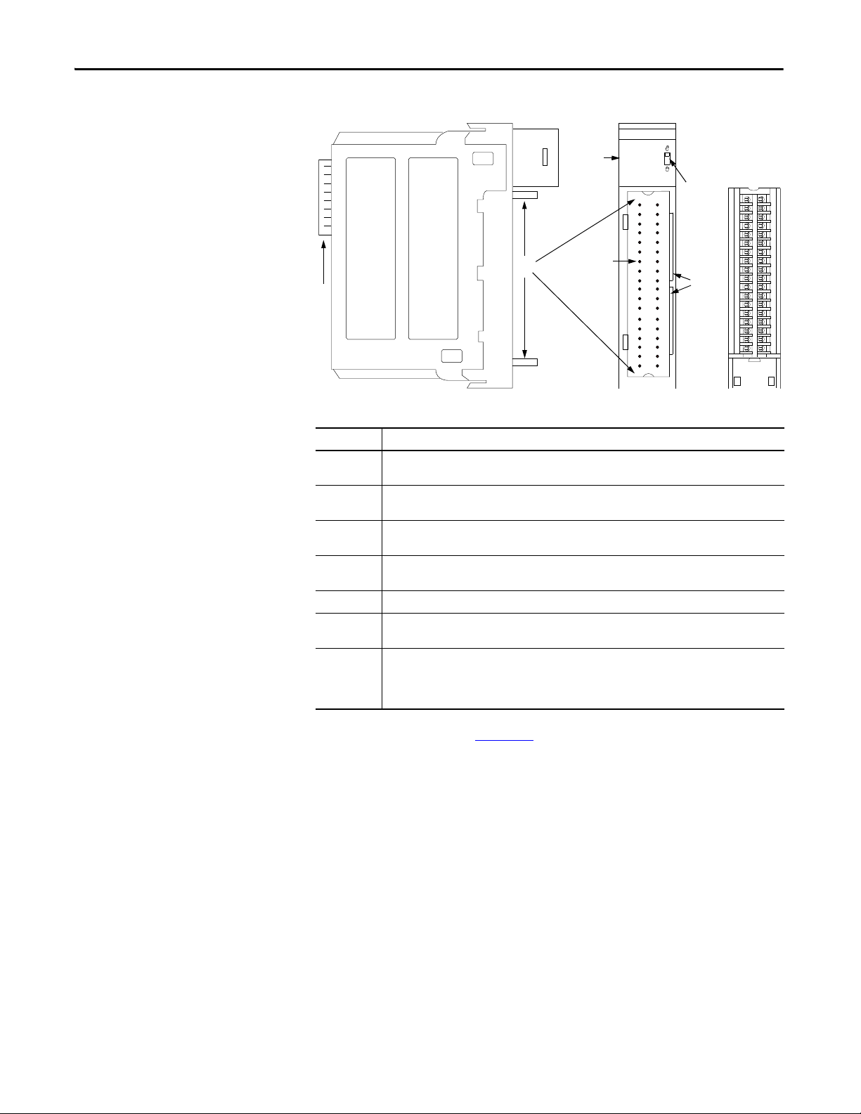
Parts Illustration
Item Description
1 Backplane connector—The backplane interface for the ControlLogix system connects the module to
the backplane.
2 Top and bottom guides—Guides provide assistance in seating the removable terminal block (RTB)
onto the module.
3 Connector pins—Input/output, power, and grounding connections are made to the module through
these pins with the use of an RTB.
4 Status indicators—Indicators display the status of communication, module health, and presence of
input/output devices. Use these indicators to help in troubleshooting.
5 Locking tab—The locking tab anchors the RTB on the module and maintains wiring connections.
6 Slots for keying—The slots let you mechanically key the RTB to prevent inadvertently making the
wrong wire connections to your module.
7 Removable terminal block—The RTB lets you connect and house the wiring. The counter module
supports two types of RTBs:
• Cage clamp, catalog number 1756-TBCH
• Spring clamp, catalog number 1756-TBS6H
For wiring instructions, see Chapter 3.
10 Rockwell Automation Publication 1756-UM536A-EN-P - April 2012
Page 11
Chapter 2
11 µs
25 µs
Module Operation
Top ic Pa ge
Counters 0…7 11
Counter Control Functions 15
Output Control 23
Counters 0…7
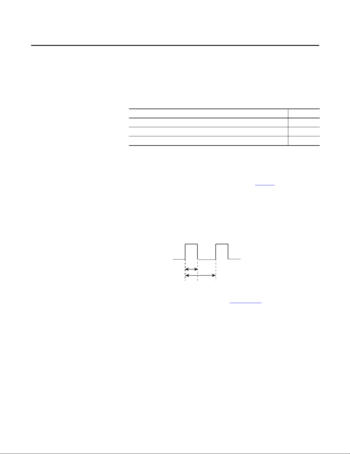
Counters 0…7 on the module are dedicated to up and down counting of
incoming pulses. The module counts rising pulse edges at a maximum of 40 kHz.
However, the following limitations apply as shown in Figure 1
• The duration of a pulse cannot be less than 11 μs, which is the minimum
hardware delay time for a transition to be detected by an input.
• For repetitive counting, the total cycle time cannot be less than 25 μs.
Figure 1 - Pulse Cycle Limits
For complete specifications, refer to the 1756 ControlLogix I/O Modules
Specifications Technical Data, publication 1756-TD002
:
.
Rockwell Automation Publication 1756-UM536A-EN-P - April 2012 11
Page 12

Chapter 2 Module Operation
Each of the eight counters automatically returns the values described in Ta b l e 3 .
Table 3 - Counter Values
Value Data Type Description
Accumulated count DINT The total number of pulses. The module counts pulses on their rising edge. The module stores accumulated count in the Counter[x].Count
Instantaneous frequency REAL The frequency of the last pulse detected by a counter. The module calculates frequency by timing from rising edge to rising edge of the
Average frequency
(1)(2)
REAL The average frequency of pulses. The module calculates average frequency over the number of pulses defined in the
Instantaneous pulse width REAL The duration in microseconds of the last rising pulse edge to falling pulse edge. The accuracy of the instantaneous pulse width is always
(1)
Average pulse width
REAL The average width of pulses. The module calculates average pulse width over the number of pulses specified in the
input tag.
last two pulses (cycle time):
• If the cycle time is less than the frequency timeout (Counter[x].FreqTimeout) value, then instantaneous frequency = 1/cycle time.
• If the cycle time is greater than the frequency timeout (Counter[x].FreqTimeout) value, then instantaneous frequency = 0.
In instantaneous frequency calculations, the rising edge of the pulse that completes a cycle time is also the rising edge of the pulse that
starts the next cycle time.
To determine the accuracy of the instantaneous frequency value, use this formula:
0.0011 x Counter[x].Frequency value
For example, a 1 kHz input frequency has a worst case instantaneous frequenc y value of ±1.1%.
The module stores instantaneous frequency in the Counter[x].Frequency input tag.
Counte r[x].FreqAveragePulseCount configuration tag. You can configure this number of pulses on the Counter Configuration tab of the
Module Properties dialog box.
The module calculates average frequency as follows.
1. Starts timing on the first rising pulse edge and stops timing on the Counter[x].FreqAveragePulseCount rising pulse edge.
2. Calculates frequency based on the total time from step 1 and multiplies the Counter[x].FreqAveragePulseCount value by the pulse
count.
For example, if Counter[x].FreqAveragePulseCount = 10 and the calculated frequency = 1 Hz, the average frequency = 10 Hz (10 pulses/
1 second).
If Counter[x].FreqAveragePulseCount = 10, the module updates average frequency values as follows:
• From pulses 0…9, the module does not calculate average frequency and returns a value of zero.
• From pulses 10…19, the module calculates and updates the average frequency for pulses 0…9 at pulse 10.
• From pulses 20…29, the module calculates and updates the average frequency for pulses 10…19 at pulse 20, and so on.
The module stores the average frequency in the Counter[x].FreqAverage input tag.
± -11s regardless of the actual pulse width. The module stores instantaneous pulse width in the Counter[x].PulseWidth input tag.
Counte r[x].FreqAveragePulseCount configuration tag. Frequency timeouts do not affect the pulse width average. If the input is high or
low for a long period of time, the average pulse width is not updated until the number of pulses in the
Counte r[x].FreqAveragePulseCount tag occurs.
The module calculates average pulse width as follows.
1. Stores each instantaneous pulse width for the number of pulses in the Counter[x].FreqAveragePulseCount tag.
2. Calculates the total of all pulse widths stored in step 1 and divides the total by the value in the Counter[x].FreqAveragePulseCount
tag.
If Counter[x].FreqAveragePulseCount = 10, the module calculates average pulse width as follows:
• From pulses 0…9, the module does not calculate average pulse width and returns a value of zero.
• From pulses 10…19, the module calculates average pulse width for pulses 0…9 at pulse 10.
• From pulses 20…29, the module calculates average pulse width for pulses 10…19 at pulse 20, and so on.
The accuracy of the average pulse width is always ± - 11 s/Counter[x].FreqAveragePulseCount regardless of the actual pulse width.
The module stores average pulse width in the Counter[x].PulseWidthAverage input tag.
(1) The average frequency and average pulse width may not be calculated on the same pulse due to frequency timeouts.
(2) Frequency timeouts may cause the accuracy of average frequency calculations to vary.
12 Rockwell Automation Publication 1756-UM536A-EN-P - April 2012
Page 13

Module Operation Chapter 2
IMPORTANT
On/Off Windows
Each counter has two configurable On/Off windows that compare the
accumulated count or frequency of incoming pulses to user-defined On/Off
values. When the count or frequency values are within the user-defined window
parameters, the module sets the corresponding bit in the Counter[x].InWindow0
or Counter[x].InWindow1 input tag.
The module produces data to the system on the rising and falling edge of each
On/Off window. A rising edge occurs when a count or frequency value enters the
window, and a falling edge occurs when a count or frequency value exits a
window.
You define each On/Off window by using these parameters:
• Comparison method—Defines whether the On/Off window uses
accumulated count, instantaneous frequency, or average frequency. You
define the comparison method for a window on the Counter
Configuration tab of the Module Properties dialog box.
• On and Off values—Defines the count or frequency value that results in
an On/Off status for the window. On and Off values represent counts or
frequency depending on the window’s comparison method. You define
these values in a set of output tags for each window:
– Counter[x].Window0On and Counter[x].Window0Off
– Counter[x].Window1On and Counter[x].Window1Off
Keep in mind the following when using frequency as a window comparison
method:
• When configured to compare frequency values, window On/Off values are
still DINT (32-bit signed integers) while the returned frequency values are
REAL (32-bit IEEE float). As a result, the frequency triggers for On/Off
windows can only be defined in 1 Hz increments.
• Fluctuations in high frequency values across window parameters could
cause the window to transition on each pulse if the input frequency is at a
window parameter and you are using instantaneous frequency as the
comparison method. In this case, the module will produce a COS message
on the backplane with each input. This high traffic could result in system
communication issues.
• For example, if you set a window Off value at 18 kHz, and the input is at
18 kHz, the instantaneous frequency calculation could result in frequency
fluctuations for each pulse between 17998.0 Hz and 18002.0 Hz. This
fluctuation would cause a COS message to be sent every 55 µs. If this
situation occurs for all eight counters, the module can generate a large
amount of backplane traffic possibly resulting in system communication
issues.
Rockwell Automation Publication 1756-UM536A-EN-P - April 2012 13
Page 14
Chapter 2 Module Operation
Counte r[x].Window0On tag = 2000
Counte r[x].Window0Off tag = 5000
Counte r[x].InWindow0
turns On at count 2000.
Counte r[x].InWindow0
remains On for 3000 counts.
Counte r[x].InWindow0
turns Off at count 5000.
On Value < Off Value
Counte r[x].Window1On = 5000
Counte r[x].Window1Off = 2000
Counte r[x].InWindow1
remains Off for 3000 counts.
Counter[x].InWindow1
turns Off at count 2000.
Counte r[x].InWindow1
turns On at count 5000.
On Value > O ff Value
EXAMPLE
Figure 2 compares two On/Off windows by using the Accumulated Count
comparison method. In the first window, the On value is less than the Off value.
In the second window, the On value is greater than the Off value.
Figure 2 - Window States Based on Accumulated Count
The Counter[x].InWindow0 and Counter[x].InWindow1 input tags can be
consumed by a controller or a 1756-OB16IEF peer output module and used to
affect outputs. For more information about using peer modules, see the
ControlLogix Peer I/O Control Application Technique, publication
1756-AT016
.
Rollover Values
A rollover value determines how many counts accumulate before the count rolls
over to zero. The count rolls over to zero on the rollover value. Each counter can
have one rollover value.
A rollover value of 100 produces the following count sequences:
• Increasing count sequence: 98, 99, 0, 1, 2…
• Decreasing count sequence: 2, 1, 0, 99, 98…
For real-time control, you define a rollover value in the Counter[x].Rollover
output tag. The following criteria applies to a rollover value:
31
• The default rollover value is a maximum count of 2
• A rollover value must be a positive DINT value. If an invalid rollover value
31
is defined, the module will use a value of 2
.
.
14 Rockwell Automation Publication 1756-UM536A-EN-P - April 2012
Page 15

Module Operation Chapter 2
Counter Control Functions
The counter module provides four counter control functions:
• Up/Down Count
• Count Enable
• Reset Count
• Preset Count
The module provides two methods to invoke counter control functions:
• Hardware inputs—You can tie counter control functions to standard
hardware inputs 0…7 to let the state of external input devices directly
control the functionality of a designated counter. To configure this
method, you use the Input Configuration tab within the module’s
properties to set up ties as shown in Figure 3 on page 16
• Output tags—The output tag method enables you to programmatically
control the counter functions via the module’s output tags. This method
offers the most flexibility in invoking counter control functions. However,
the response time is limited due to the time required for the controller to
process your application routine.
Keep in mind the following when tying hardware inputs to counter control
functions:
.
• A single input can control functionality for multiple counters. For
example, you can tie input 3 to the Up/Down Count function for all eight
counters.
• Only one type of counter control function can be tied to a single input. For
example, you cannot tie both the Count Enable and Reset Count
functions to the same input.
• If you do not require hardware inputs 0…7 to support counter control
functionality, you can use the inputs as general purpose On/Off inputs
without timestamping.
Rockwell Automation Publication 1756-UM536A-EN-P - April 2012 15
Page 16
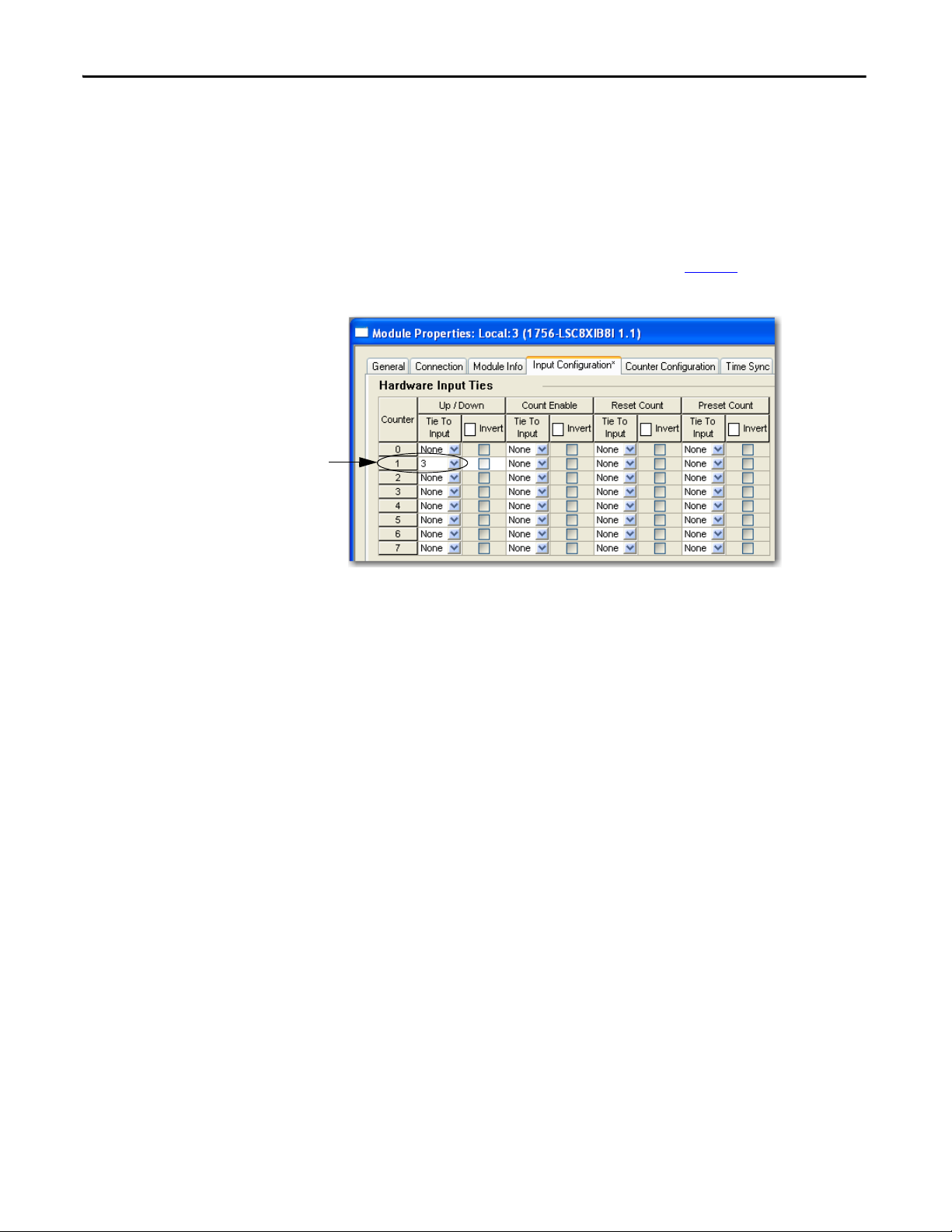
Chapter 2 Module Operation
Up/Down Count function for counter 1
is tied to hardware inp ut 3.
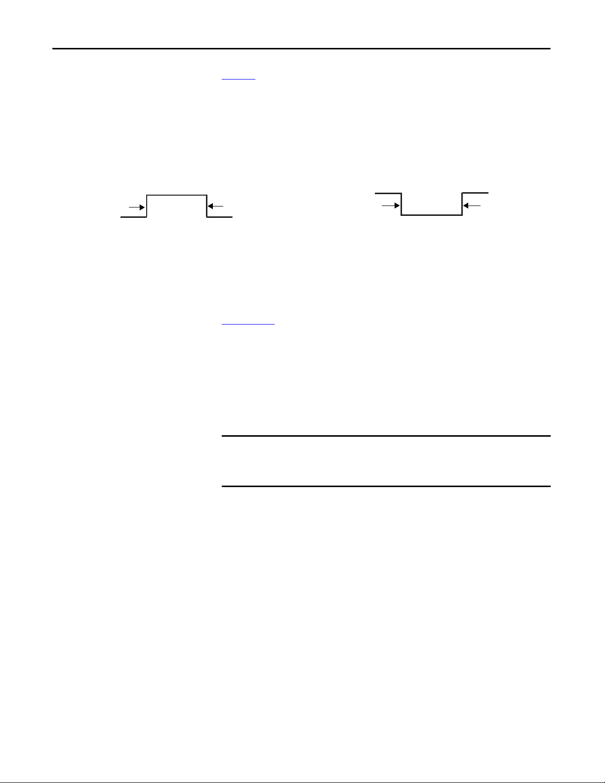
Up/Down Count Function
The Up/Down Count function causes a counter to increment or decrement
accumulated count or changes the direction bit for frequency values.
To invoke the Up/Down Count function for a counter by using the hardware
input method, tie the function to a hardware input on the Input Configuration
tab of the Module Properties dialog box as shown in Figure 3
Figure 3 - Up/Down Count Function Controlled by Hardware Input
.
When tied to a hardware input, this function is level-sensitive resulting in a
change of status when the input is either low or high:
• By default, the count direction goes up when the input is low and down
when the input is high.
• When the function is inverted, the count direction goes up when an input
is high and down when the input is low.
16 Rockwell Automation Publication 1756-UM536A-EN-P - April 2012
Page 17
Module Operation Chapter 2
IMPORTANT
0 = Count direction is up,
level-sensitive.
1 = Count direction is down,
level-sensitive.
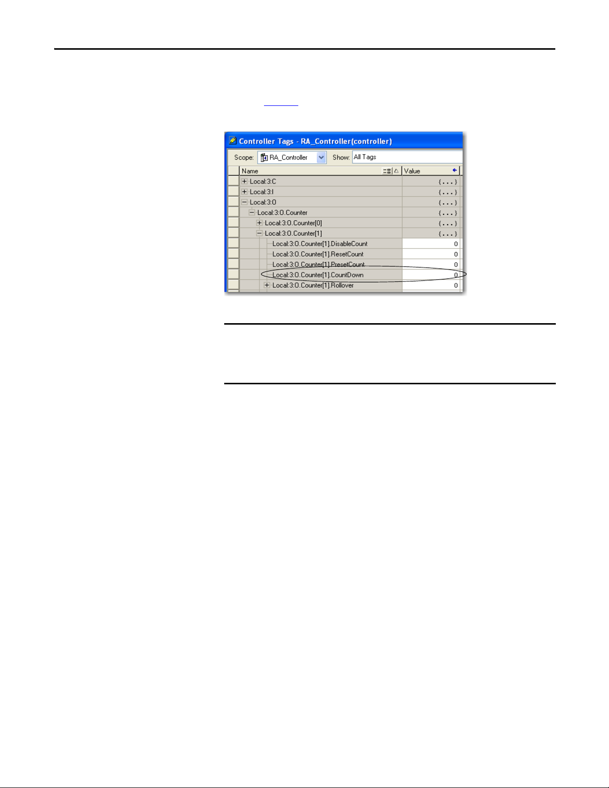
To invoke the Up/Down Count function by using the output tag method, use the
Counter[x]CountDown output tag to define the direction of Counter[x] as
shown in Figure 4
Figure 4 - Counter[x]CountDown Output Tag
. By default, the count direction is up.
The Counter[x].CountDown output tag is active only if the Up/Down Count
function is not tied to Counter[x] via a hardware input. If a hardware input is
tied to Counter[x], the hardware input overrides the value of the
Counter[x].CountDown output tag.
Rockwell Automation Publication 1756-UM536A-EN-P - April 2012 17
Page 18
Chapter 2 Module Operation
Up/Down Control Sensor
Count U p
Count Dow n
1756-LSC8XIB8I
Counte r x
Counter Control
Hardware Input x
Counti ng Senso r
Counter Control Hardware In put
+
–
3
0
1
2
Counti ng Senso r
1
2
Count Total in Counter[x].Count Tag
Frequency in Counter[x].Frequency Tag
Count Direction in Counter[x].Direction Tag
Pulse Width in Counter[x].PulseWidth Tag
New Frequency
Valu e
New Frequency
Valu e
New Frequency
Valu e
New Frequency
Valu e
New Frequency
Valu e
New Frequency
Valu e
1 1 0
0
0
1
New Pulse
Width Valu e
New Pulse
Width Valu e
New Pulse
Width Valu e
New Pulse
Width Valu e
New Pulse
Width Valu e
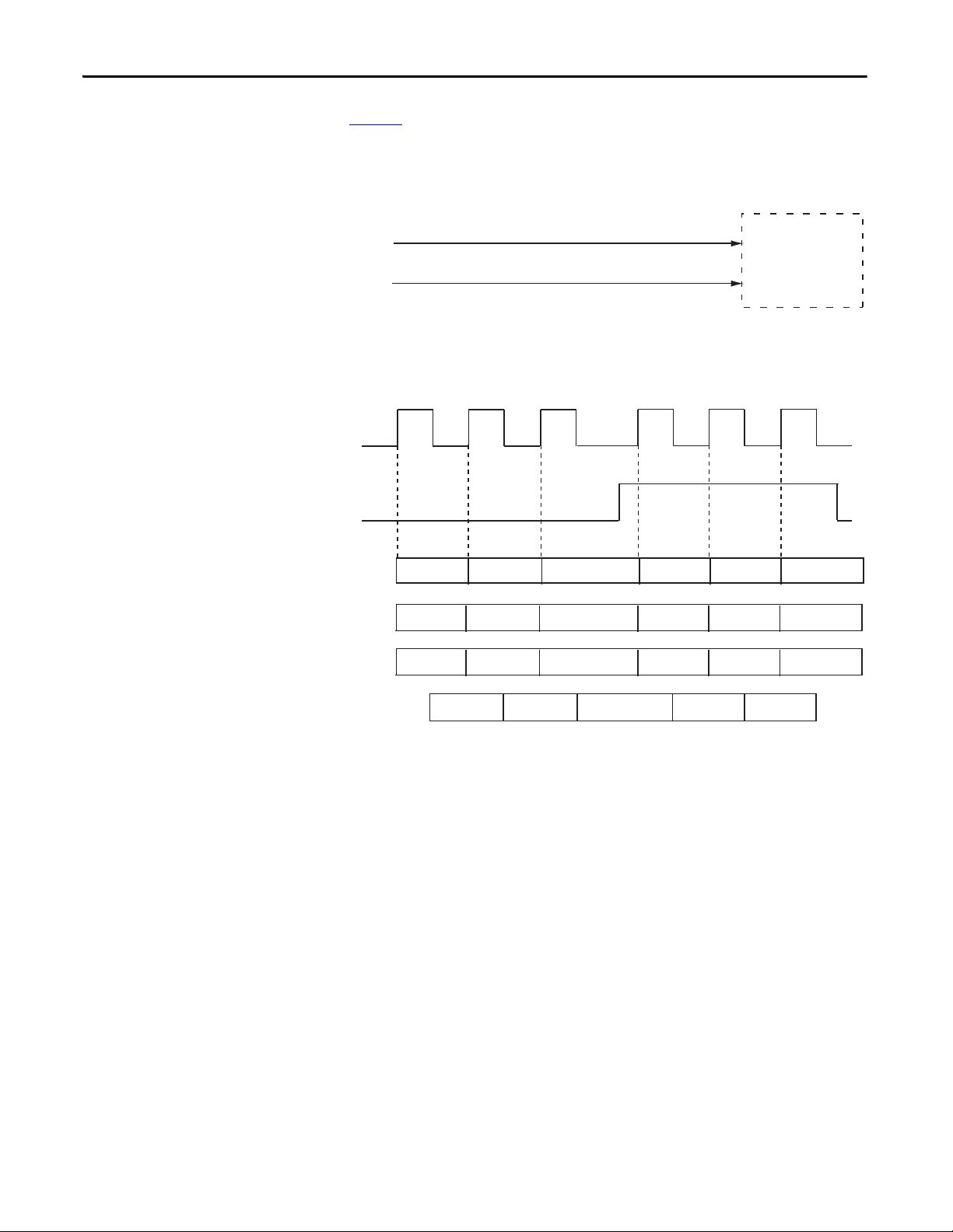
Figure 5 illustrates the input tag values returned when the Up/Down Count
function is tied to an input via a hardware input.
Figure 5 - Example of Up/Down Count Function
18 Rockwell Automation Publication 1756-UM536A-EN-P - April 2012
Page 19
Module Operation Chapter 2
Count Enable function for counter 2
is tied to hardware input 4.
0 = Counting occurs,
level-sensitive.
1 = Counting is disabled,
level-sensitive.
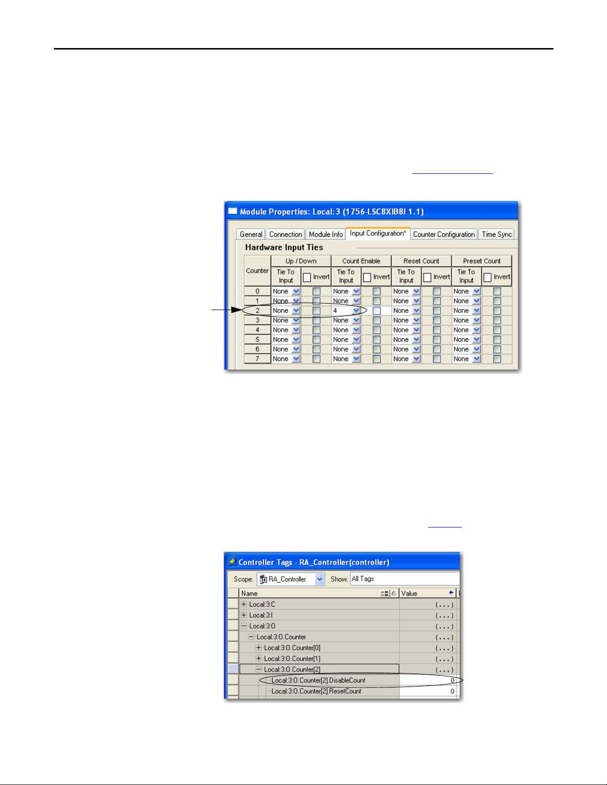
Count Enable Function
The Count Enable function serves as a gate input that controls when counting
starts and stops.
To invoke the Count Enable function for a counter by using the hardware input
method, tie the function to a hardware input on the Input Configuration tab of
the Module Properties dialog box as shown in Figure 6 on page 19
Figure 6 - Count Enable Function Controlled by Hardware Input
.
When tied to a hardware input, this function is level-sensitive resulting in a
change of status when the input is either low or high:
• By default, counting starts only when the input is high and stops when the
input is low.
• When the function is inverted, counting starts only when the input is low
and stops when the input is high.
To invoke the Count Enable function by using the output tag method, use the
Counter[x].DisableCount output tag as shown in Figure 7
Figure 7 - Counter[x]DisableCount Output Tag
.
Rockwell Automation Publication 1756-UM536A-EN-P - April 2012 19
Page 20
Chapter 2 Module Operation
IMPORTANT
Reset Count function for counter 3
is tied to hardware input 5.
Note that the module continues to calculate frequency and pulse width values
even if you disable counting via the Count Enable function.
Either the Count Enable hardware input or the corresponding bit in the
Counter[x]DisableCount output tag can determine whether counting is
enabled or disabled.
Counting is enabled under the following conditions:
• Counter[x].CountEnTieToPt configuration tag = -1 (no tie) or 0…7 and the
corresponding hardware input is non-inverted and high or inverted and
low (level-sensitive)
and
• Counter[x]DisableCount output tag = 0 (level-sensitive)
Counting is disabled under these conditions:
• Counter[x].CountEnTieToPt configuration tag = 0…7 and the
corresponding hardware input is non-inverted and low or inverted and
high (level-sensitive)
or
• Counter[x]DisableCount output tag = 1 (level-sensitive)
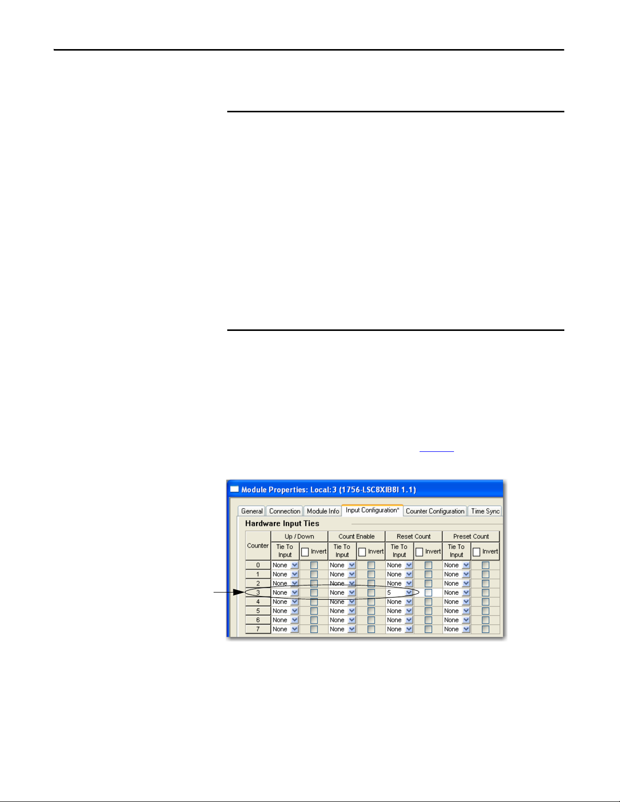
Reset Count Function
The Reset Count function resets the count to zero.
To invoke the Reset Count function for a counter by using the hardware input
method, tie the function to a hardware input on the Input Configuration tab of
the Module Properties dialog box as shown in Figure 8
Figure 8 - Reset Count Function Controlled by Hardware Input
.
When tied to a hardware input, this function is edge-sensitive resulting in a reset
when the designated input transitions low or high:
• By default, counting resets to zero on a rising pulse edge.
• When the function is inverted, counting resets to zero on a falling pulse
edge.
20 Rockwell Automation Publication 1756-UM536A-EN-P - April 2012
Page 21
Module Operation Chapter 2
IMPORTANT
EXAMPLE
0 = Tag-based reset is not
active.
1 = Count transitions to zero
on a rising edge.
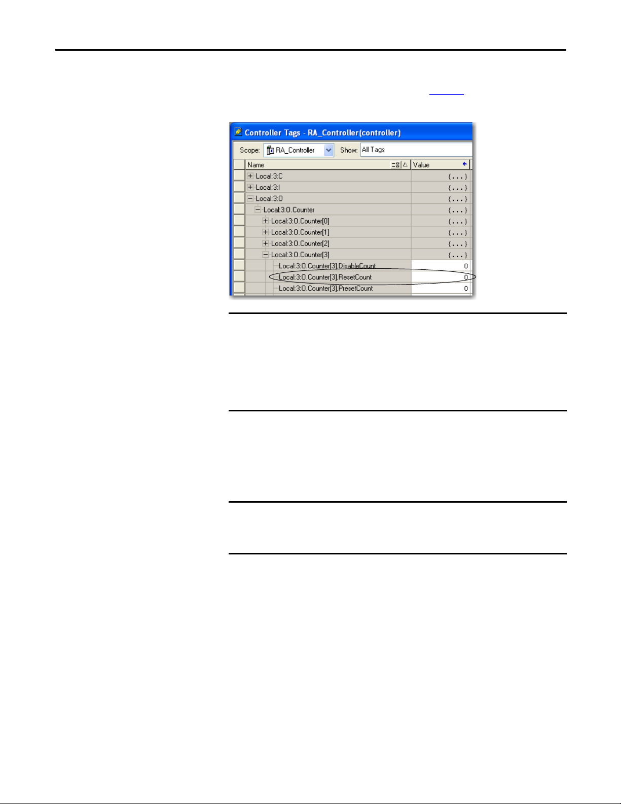
To invoke the Reset Count function by using the output tag method, use the
Counter[x].ResetCount output tag as shown in Figure 9
Figure 9 - Counter[x]ResetCount Output Tag
.
Either the Reset Count hardware input or the corresponding bit in the
Counter[x]ResetCount output tag can determine whether the count is reset.
Counting is reset to zero under the following conditions:
• Counter[x].ResetTieToPt configuration tag = 0…7 (rising edge-sensitive)
or
• Counter[x]ResetCount output tag = 1 (rising edge-sensitive)
Preset Count Function
A preset value determines the starting value for a count. Each counter can have
one preset value defined in the Counter[x].Preset output tag.
A preset value of 99 produces the following count sequences:
• Increasing count sequence: 99, 100, 101, …
• Decreasing count sequence: 99, 98, 97, …
The following criteria applies to a preset value:
• The default preset value is zero.
• A preset value must be a non-negative DINT value.
• A preset value must be less than the rollover value. If the preset value is
greater than or equal to the rollover value, then the module uses the
requested rollover value and the default preset value of zero rather than the
invalid preset value.
Rockwell Automation Publication 1756-UM536A-EN-P - April 2012 21
Page 22
Chapter 2 Module Operation
Preset Count function for counter 4
is tied to hardware input 7.
0 = Tag-based preset not
active.
1 = Count transitions to the
preset value on a rising edge.
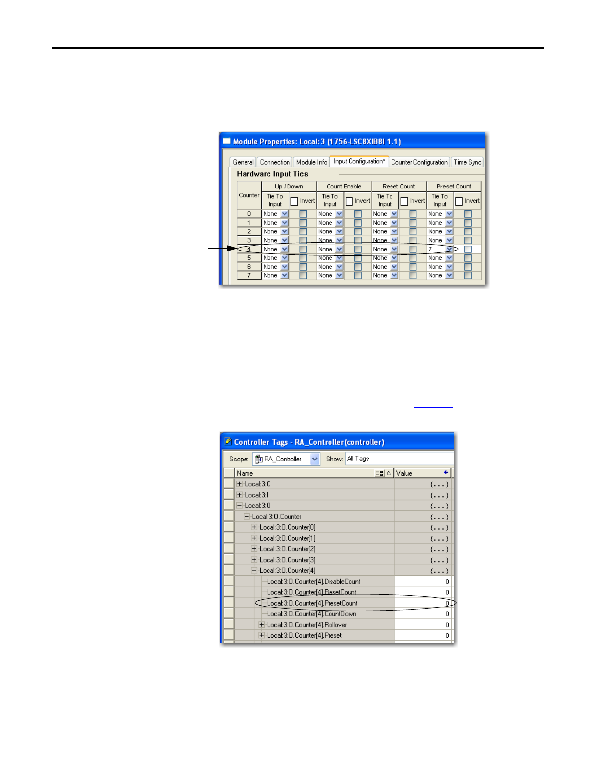
To invoke the Preset Count function for a counter by using the hardware input
method, tie the function to a hardware input on the Input Configuration tab of
the Module Properties dialog box as shown in Figure 10
Figure 10 - Preset Count Function Controlled by Hardware Input
.
When tied to a hardware input, this function is edge-sensitive resulting in a preset
when the designated input transitions low or high:
• By default, the count is set to the preset value on a rising pulse edge.
• When the function is inverted, the count is set to the preset value on a
falling pulse edge.
To invoke the Preset Count function by using the output tag method, use the
Counter[x].PresetCount output tag as shown in Figure 11
Figure 11 - Counter[x]PresetCount Output Tag
.
22 Rockwell Automation Publication 1756-UM536A-EN-P - April 2012
Page 23

Module Operation Chapter 2
IMPORTANT
Either the Preset Count hardware input or the corresponding bit in the
Counter[x]PresetCount output tag can determine whether the count is preset.
The count is preset to the Counter[x].Preset value under the following
conditions:
• Counter[x].PresetTieToPt configuration tag = 0…7 (rising edge-sensitive)
or
• Counter[x]PresetCount output tag = 1 (rising edge-sensitive)
Output Control
Inputs from the counter module can affect outputs on a 1756-OB16IEF module.
The output module consumes data from these input tags on a peer module:
• Pt[x]Data—Indicates the current On/Off value of the corresponding
hardware input.
• Counter[x]InWindow0—Indicates whether the accumulated count or
frequency value of Counter[x] is within the parameters defined by the
Counter[x].Window0On and Counter[x].Window0Off output tags. A
change in window status triggers a Change of State (COS) message to be
sent to the owner-controller or peer module.
• Counter[x]InWindow1—Indicates whether the accumulated count or
frequency value of Counter[x] is within the parameters defined by the
Counter[x].Window1On and Counter[x].Window1Off output tags. A
change in window status triggers a Change of State (COS) message to be
sent to the owner-controller or peer module.
You can define the output behavior on the 1756-OB16IEF module by applying
Boolean logic to the On/Off windows, inputs, and any bits from the controller.
To establish communication with an input module, the output module sends a
Listen-only connection request to the input module. Once the connection is
established, the output module can consume data directly from the input
module.
For more information about peer control, refer to the Peer I/O Control
Application Technique, publication 1756-AT016
Rockwell Automation Publication 1756-UM536A-EN-P - April 2012 23
.
Page 24

Chapter 2 Module Operation
Notes:
24 Rockwell Automation Publication 1756-UM536A-EN-P - April 2012
Page 25
Chapter 3
Install the Counter Module
Top ic Pa ge
Install the Module 27
Key the Removable Terminal Block 29
Connec t the Wires 30
Wire Terminations 33
Assemble the Removable Terminal Block and Housing 35
Install the Removable Terminal Block 36
Remove the Removable Terminal Block 38
Remove the Module from the Chassis 39
ATTENTION: Environment and Enclosure
This equipment is intended for use in a Pollution Degree 2 industrial environment, in overvoltage Category II applications (as
defined in IEC 60664-1), at altitudes up to 2000 m (6562 ft) without derating.
This equipment is considered Group 1, Class A industrial equipment according to IEC/CISPR 11. Without appropriate
precautions, there may be difficulties with electromagnetic compatibility in residential and other environments due to
conducted and radiated disturbances.
This equipment is supplied as open-type equipment. It must be mounted within an enclosure that is suitably designed for those
specific environmental conditions that will be present and appropriately designed to prevent personal injury resulting from
accessibility to live parts. The enclosure must have suitable flame-retardant properties to prevent or minimize the spread of
flame, complying with a flame spread rating of 5VA or be approved for the application if nonmetallic. The interior of the
enclosure must be accessible only by the use of a tool. Subsequent sections of this publication may contain additional
information regarding specific enclosure type ratings that are required to comply with certain product safety certifications.
In addition to this publication, see the following:
• Industrial Automation Wiring and Grounding Guidelines, publication 1770-4.1
, for additional installation requirements.
• NEMA Standard 250 and IEC 60529, as applicable, for explanations of the degrees of protection provided by enclosures.
Rockwell Automation Publication 1756-UM536A-EN-P - April 2012 25
Page 26
Chapter 3 Install the Counter Module
North American Hazardous Location Approval
The following information applies when operating this equipment in
hazardous locations.
Products marked "CL I, DIV 2, GP A, B, C, D" are suitable for use in Class I Division 2 Groups
A, B, C, D, Hazardous Locations and nonhazardous locations only. Each product is supplied
with markings on the rating nameplate indicating the hazardous location temperature
code. When combining products within a system, the most adverse temperature code
(lowest "T" number) may be used to help determine the overall temperature code of the
system. Combinations of equipment in your system are subject to investigation by the
local Authority Having Jurisdiction at the time of installation.
Informations sur l’utilisation de cet équipement en environnements
dangereux.
Les produits marqués "CL I, DIV 2, GP A, B, C, D" ne conviennent qu'à une utilisation en
environnements de Classe I Division 2 Groupes A, B, C, D dangereux et non dangereux.
Chaque produit est livré avec des marquages sur sa plaque d'identification qui indiquent
le code de température pour les environnements dangereux. Lorsque plusieurs produits
sont combinés dans un système, le code de température le plus défavorable (code de
température le plus faible) peut être utilisé pour déterminer le code de température
global du système. Les combinaisons d'équipements dans le système sont sujettes à
inspection par les autorités locales qualifiées au moment de l'installation.
WARNING: EXPLOSION HAZARD
• Do not disconnect equipment unless power has
been removed or the area is known to be
nonhazardous.
• Do not disconnect connections to this
equipment unless power has been removed or
the area is known to be nonhazardous. Secure
any external connections that mate to this
equipment by using screws, sliding latches,
threaded connectors, or other means provided
with this product.
• Substitution of components may impair
suitability for Class I, Division 2.
• If this product contains batteries, they must only
be changed in an area known to be
nonhazardous.
European Hazardous Location Approval
The following applies when the product bears the Ex Marking.
This equipment is intended for use in potentially explosive atmospheres as defined by European Union Directive 94/9/EC and has been found to comply with the Essential Health and
Safety Requirements relating to the design and construction of Category 3 equipment intended for use in Zone 2 potentially explosive atmospheres, given in Annex II to this Directive.
Compliance with the Essential Health and Safety Requirements has been assured by compliance with EN 60079-15 and EN 60079-0.
WARNING: RISQUE D’EXPLOSION
• Couper le courant ou s'assurer que
l'environnement est classé non dangereux avant
de débrancher l'équipement.
• Couper le courant ou s'assurer que
l'environnement est classé non dangereux avant
de débrancher les connecteurs. Fixer tous les
connecteurs externes reliés à cet équipement à
l'aide de vis, loquets coulissants, connecteurs
filetés ou autres moyens fournis avec ce produit.
• La substitution de composants peut rendre cet
équipement inadapté à une utilisation en
environnement de Classe I, Division 2.
• S'assurer que l'environnement est classé non
dangereux avant de changer les piles.
ATTENTION: This equipment is not resistant to sunlight or other sources of UV radiation.
WARNING:
• This equipment must be installed in an enclosure providing at least IP54 protection when applied in Zone 2 environments.
• This equipment shall be used within its specified ratings defined by Rockwell Automation.
• Provision shall be made to prevent the rated voltage from being exceeded by transient disturbances of more than 40%
when applied in Zone 2 environments.
• This equipment must be used only with ATEX certified Rockwell Automation backplanes.
• Secure any external connections that mate to this equipment by using screws, sliding latches, threaded connectors, or other
means provided with this product.
• Do not disconnect equipment unless power has been removed or the area is known to be nonhazardous.
26 Rockwell Automation Publication 1756-UM536A-EN-P - April 2012
Page 27

Install the Counter Module Chapter 3
Install the Module
You can install or remove the module while chassis power is applied.
WARNING: When you insert or remove the module while backplane power is
on, an electrical arc can occur. This could cause an explosion in hazardous
location installations.
Be sure that power is removed or the area is nonhazardous before proceeding.
Repeated electrical arcing causes excessive wear to contacts on both the module
and its mating connector. Worn contacts may create electrical resistance that can
affect module operation.
The module is sensitive to electrostatic discharge when handled outside of the
chassis. The module has been tested to withstand an electrostatic discharge while
operating within the chassis.
ATTENTION: Prevent Electrostatic Discharge
This equipment is sensitive to electrostatic discharge, which can cause internal
damage and affect normal operation. Follow these guidelines when you handle
this equipment:
• Touch a grounded object to discharge potential static.
• Wear an approved grounding wriststrap.
• Do not touch connectors or pins on component boards.
• Do not touch circuit components inside the equipment.
• Use a static-safe workstation, if available.
• Store the equipment in appropriate static-safe packaging when not in use.
Rockwell Automation Publication 1756-UM536A-EN-P - April 2012 27
Page 28

Chapter 3 Install the Counter Module
Top Gu ide
Bottom Guide
20861-M
Locking Tab
20862-M
Follow these steps to insert the module into the chassis.
1. Align the circuit board with the top and bottom chassis guides.
2. Slide the module into the chassis until the locking tabs click.
28 Rockwell Automation Publication 1756-UM536A-EN-P - April 2012
Page 29

Install the Counter Module Chapter 3
20850-M
Key the Removable Termina l Bl ock
Key the removable terminal block (RTB) to prevent inadvertently connecting the
wrong wiring in the RTB to your module. Wedge- and U-shaped bands are
manually inserted into the RTB and module. This process hinders a wired RTB
from being accidentally inserted into a module that does not match the
positioning of the respective tabs.
Key positions on the module that correspond to unkeyed positions on the RTB.
For example, if you place a U-shaped keying band in slot 4 on the module, do not
insert a wedge-shaped tab in slot 4 on the RTB, or your RTB will not mount on
the module. We recommend that you use a unique keying pattern for each slot in
the chassis.
Follow these steps to key the RTB.
1. To key the module, insert the U-shaped band with the longer side near the
terminals.
2. Push the band onto the module until it snaps into place.
Rockwell Automation Publication 1756-UM536A-EN-P - April 2012 29
Page 30

Chapter 3 Install the Counter Module
Module Side of RTB
20851-M
0
1
2
3
4
5
6
7
3. To key the RTB in positions that correspond to unkeyed module positions,
insert the straight, wedge-shaped tab on the RTB with the rounded edge
first.
4. Push the tab onto the RTB until it stops.
Connect the Wires
5. Repeat step 1
…step 4 by using additional U-shaped and straight tabs until
the module and RTB lock into each other properly.
Before wiring the module, adhere to these wiring guidelines.
WARNING: If you connect or disconnect wiring while the field-side power is on,
an electrical arc can occur. This could cause an explosion in hazardous location
installations. Be sure that power is removed or the area is nonhazardous before
proceeding.
ATT EN TI ON : If multiple power sources are used, do not exceed the specified
isolation voltage.
ATT EN TI ON : When using the 1756-TBCH, do not wire more than two
0.33…1.3 mm
2
(22…16 AWG) conductors on any single terminal. Use only
the same size wires with no intermixing of solid and stranded wire types.
When using the 1756-TBS6H, do not wire more than one conductor on any single
terminal.
30 Rockwell Automation Publication 1756-UM536A-EN-P - April 2012
Page 31

Install the Counter Module Chapter 3
20859-M
Strain Relief Area
Use an RTB
(1)
or interface module (IFM) to connect wires to your module. To
use an RTB, follow the directions below to connect wires to the RTB. IFMs are
prewired prior to shipping. The counter module supports IFM catalog numbers
1492-IFM40F, 1492-IFM40DS24A-4, 1492-IFM40F-FS24A-4, and
1492-IFM40F-FSA-4.
RTB Types
Use one of these types of RTBs with your counter module:
• Cage clamp, catalog number 1756-TBCH
• Spring clamp, catalog number 1756-TBS6H
ATT EN TI ON : The ControlLogix system has been agency certified using only the
ControlLogix RTBs 1756-TBCH, 1756-TBNH, 1756-TBSH, and 1756-TBS6H). Any
application that requires agency certification of the ControlLogix system using
other wiring termination methods may require application specific approval by
the certifying agency.
Each RTP comes with housing. Wire the RTB with a 3.2 mm (1/8 in.) maximum
screwdriver before installing it onto the module.
Cage Clamp
Follow these steps to wire a cage clamp.
1. Strip 9.5 mm (3/8 in.) maximum length of wire.
2. Insert the wire into the open terminal on the side.
3. Turn the screw clockwise to close the terminal on the wire.
The open section at the bottom of the RTB is called the strain relief area. The
wiring from the connections can be grouped with a plastic tie.
(1) The ControlLogix system has been agency certified using only the ControlLogix RTBs (1756-TBCH, 1756-TBNH, 1756-TBSH, and
1756-TBS6H). Any application that requires agency certification of the ControlLogix system using other wiring termination methods
may require application specific approval by the certifying age ncy.
Rockwell Automation Publication 1756-UM536A-EN-P - April 2012 31
Page 32

Chapter 3 Install the Counter Module
IMPORTANT
20860-M
Strain Relief Area
Spring Clamp
Follow these steps to wire a spring clamp.
1. Strip 11 mm (7/16 in.) maximum length of wire.
2. Insert the screwdriver into the outer hole of the RTB to depress the spring-
loaded clamp.
3. Insert the wire into the open terminal and remove the screwdriver.
Make sure the wire, and not the screwdriver, is inserted into the open terminal
to prevent damage to the module.
The open section at the bottom of the RTB is called the strain relief area. The
wiring from the connections can be grouped with a plastic tie.
RTB Wiring Recommendations
Consider these guidelines when wiring your RTB:
• Begin wiring the RTB at the bottom terminals and move up.
• Use a tie to secure the wires in the strain relief area of the RTB.
• A jumper bar is shipped with certain I/O modules to assist in installation.
Additional jumper bars can be purchased in packages of 25 by ordering
catalog number 1756-JMPR.
• For applications that require heavy gauge wiring, order and use an
extended-depth housing, catalog number 1756-TBE.
32 Rockwell Automation Publication 1756-UM536A-EN-P - April 2012
Page 33

Install the Counter Module Chapter 3
Simplified Schematic
ControlLogix Backplane Interface
Module Display
GND-x or CTR GND-x
IN-x or CTR-x
1756-LSC8XIB8I
Current Limiter
Daisy Chain to Other RTBs
Module Source Input Wiring
Jumper Bar Cut to Length
Nonisolated Wiring
Isolated Wiring
Module Sink Input Wiring
See Figure 13
for
proximity sensor wiring.
Wire Terminations
The following diagrams provide wiring examples for the eight counter, eight
input point, 24V high-speed DC isolated, sink/source input module. For
alternate wiring for use with non-IEC Type 3 sensors, refer to Appendix
Figure 12 - Device Wiring
DC-5(-)
DC-6(-)
DC (-)
DC-1(-)
DC-2(-)
GND-0
GND-1
GND-2
GND-3
GND-4
GND-5
GND-6
GND-7
CTR-GND-0
CTR GND-1
CTR GND-2
CTR GND- 3
CTR GND-4
CTR GNDCTR GNDCTR GNDCTR GND-
Not Used
5
6
7
7
2
4
6
8
019
2111
4131
6151
8171
0291
2212
4232
6252
8272
0392
2313
4333
6353
1
3
5
7
IN-0
IN-1
IN-2
IN-3
IN-4
IN-5
IN-6
IN-7
CTR-0
CTR-1
CTR-2
CTR-3
CTR-4
CTR-5
CTR-6
CTR-7
Not Used
Not Used
DC-1(+)
DC-2(+)
(+)
(+)
DC-5(+)
DC-6(+)
D.
DC (+)
Rockwell Automation Publication 1756-UM536A-EN-P - April 2012 33
Page 34

Chapter 3 Install the Counter Module
1
3
5
7
019
2111
4131
6151
8171
0291
2212
4232
6252
8272
0392
2313
4333
6353
GND-0
GND-1
GND-2
GND-3
CTR-GND-0
GND-4
GND-5
GND-6
GND-7
Not Used
CTR GND-1
CTR GND-2
CTR GND- 3
CTR GND-4
5
6
7
7
IN-0
IN-1
IN-2
IN-3
CTR-0
IN-4
IN-5
IN-6
IN-7
Not Used
Not Used
CTR GNDCTR GNDCTR GNDCTR GND-
CTR-1
CTR-2
CTR-3
CTR-4
CTR-5
CTR-6
CTR-7
2
4
6
8
Black
Blue
12…24V DC
12…24V DC Return
Brown
1756-LSC8XIB8I
Counter Control
Hardware Inputs 0…7
Counters 0…7
Allen-Bradley Bulletin 872 3-wire DC
Proximity Sensor—Normally Open NPN
Allen-Bradley Bulletin 872 3-wire DC
Proximity Sensor—Normally Open PNP
Black
Blue
12…24V DC Return
Brown
Module Sink Input Wiring
Module Source Input Wiring
12…24V DC
Figure 13 - Electronic Device Wiring
34 Rockwell Automation Publication 1756-UM536A-EN-P - April 2012
Page 35

Install the Counter Module Chapter 3
1
4
2
2
3
3
5
20858-M
IMPORTANT
Assemble the Removable Terminal Block and Housing
Removable housing covers the wired RTB to protect wiring connections when
the RTB is seated on the module. Parts of the 1756-TBCH RTB are identified in
the table.
Item Description
1 Housing cover
2 Groove
3 Side edge of RTB
4RTB
5 Strain relief area
Follow these steps to attach the RTB to the housing.
1. Align the grooves at the bottom of each side of the housing with the side
edges of the RTB.
2. Slide the RTB into the housing until it snaps into place.
If additional wire routing space is required for your application, use the
extended-depth housing, catalog number 1756-TBE.
Rockwell Automation Publication 1756-UM536A-EN-P - April 2012 35
Page 36

Chapter 3 Install the Counter Module
Top Gu ide
Bottom Guide
20853-M
Install the Removable Terminal Block
This section shows how to install the RTB onto the module to connect the
wiring.
WARNING: When you connect or disconnect the removable terminal block
(RTB) with field side power applied, an electrical arc can occur. This could cause
an explosion in hazardous location installations.
Be sure that power is removed or the area is nonhazardous before proceeding.
Before installing the RTB, make sure of the following:
• Field-side wiring of the RTB has been completed.
• The RTB housing is snapped into place on the RTB.
• The RTB housing door is closed.
• The locking tab at the top of the module is unlocked.
1. Align the top, bottom, and left side guides of the RTB with the guides on
the module.
36 Rockwell Automation Publication 1756-UM536A-EN-P - April 2012
Page 37

Install the Counter Module Chapter 3
20854-M
2. Press quickly and evenly to seat the RTB on the module until the latches
snap into place.
3. Slide the locking tab down to lock the RTB onto the module.
Rockwell Automation Publication 1756-UM536A-EN-P - April 2012 37
Page 38

Chapter 3 Install the Counter Module
20855-M
Remove the Removable Terminal Block
If you need to remove the module from the chassis, you must first remove the
RTB from the module.
1. Unlock the locking tab at the top of the module.
2. Open the RTB door by using the bottom tab.
3. Hold the spot marked PULL HERE and pull the RTB off the module.
38 Rockwell Automation Publication 1756-UM536A-EN-P - April 2012
Page 39

Install the Counter Module Chapter 3
20856-M
20857-M
Remove the Module from the Chassis
Follow these steps to remove a module from its chassis.
1. Push in the top and bottom locking tabs.
2. Pull the module out of the chassis.
Rockwell Automation Publication 1756-UM536A-EN-P - April 2012 39
Page 40

Chapter 3 Install the Counter Module
Notes:
40 Rockwell Automation Publication 1756-UM536A-EN-P - April 2012
Page 41

Chapter 4
Configure the Module
Top ic Pag e
ControlLogix Overview 41
Create a New Module 46
Configure Connection Properties 48
Configure Counters 0…7 50
Configure Hardware Inputs 0…7 53
Download the Configuration 56
ControlLogix Overview
Before configuring your module in a local or remote chassis, you must have an
understanding of how the module operates with the controller in the
ControlLogix system. Every module must be owned by a Logix5000 controller.
This owner-controller stores configuration data for every module that it owns.
The owner-controller sends configuration data to the modules it owns when the
module powers up or during a controller-initiated reconfiguration. Adding the
module to the I/O configuration tree in the RSLogix 5000 software creates
configuration and I/O data structures and tags for the module.
Figure 14 on page 42
controller.
shows how the module communicates with its owner-
Rockwell Automation Publication 1756-UM536A-EN-P - April 2012 41
Page 42

Chapter 4 Configure the Module
ST
O
K
COUNTER
CTR
PEER DEVICE
0 1 2 3 4 5 6 7
0 1 2 3 4 5 6 7
Logix Co ntroller Counter Module
1
2
3
4
5
Tag s
Program Logic
Figure 14 - Module Communication with Owner-controller
Path No. Description
1 Controller transfers configuration data and commands to the module.
2 External devices generate input signals that are transmitted to the module.
3 Module converts signals, counts incoming pulses, calculates frequency and pulse width values, and then
stores the values.
4 Counter module transfers data, including accumulated count and frequency values, to the controller. The
controller stores the data in descriptive tags.
If configured, a 1756-OB16IEF peer module also consumes the data via a Listen-only connection to the
counter module. The peer output module evaluates the input data and applies the data to its outputs by
using program logic from the controller.
5 Program logic can store and move data before new input data is broadcast over the backplane and
overwrites the current input data in the controller’s tags. Program logic also updates values in output tags
that are sent to the counter module, such as preset and rollover values.
IMPORTANT: In RSLogix 5000 software, versions 18.02.00 and later, output tag information is sent to the
counter module only at the RPI rate defined during configuration. For optimal performance, use an
Immediate Output (IOT) instruction.
For example, the rung shown below contains an IOT instruction for a counter module in slot 3. Add a
similar rung to your last routine within the Main Task to mimic normal output tag processing.
A module’s communication, or multicasting, behavior varies depending upon
whether it operates in the local chassis or in a remote chassis.
42 Rockwell Automation Publication 1756-UM536A-EN-P - April 2012
Page 43

Configure the Module Chapter 4
IMPORTANT
Direct Connections
A direct connection is a real-time data transfer link between the controller and
the device that occupies the slot that the configuration data references. When
module configuration data is downloaded to an owner-controller, the controller
attempts to establish a direct connection to each of the modules referenced by the
data.
One of the following occurs:
• If the data is appropriate to the module found in the slot, a connection is
made and operation begins.
• If the configuration data is not appropriate, the data is rejected and an
error message appears in the software. In this case, the configuration data
can be inappropriate for any of a number of reasons. For example, a
module’s configuration data may be appropriate except for a mismatch in
electronic keying that prevents normal operation.
The controller maintains and monitors its connection with a module. Any break
in the connection, such as removal of the module from the chassis while under
power, causes the controller to set faults in the data area associated with the
module. The RSLogix 5000 software may monitor this data area to signal the
module’s failures.
The time frame in which a module produces its data depends on the options
chosen during configuration and where in the control system the module
physically resides, such as locally or remotely.
Local Chassis Operation
A local chassis contains the module and its owner-controller. If a module resides
in a local chassis, the requested packet interval (RPI) instructs the module to send
its channel and status data to the local chassis backplane at specific time intervals.
The RPI value is set during the initial module configuration by using
RSLogix 5000 software as described in Configure Connection Properties
page 48. The RPI value can be adjusted when the controller is in Program
mode.
In addition to producing data at the RPI, the module also produces data when a
change in status occurs for the following input tags:
• Counter[x].InWindow0 or Counter[x].InWindow1—Indicates whether the
accumulated count or frequency value of Counter[x] is within the defined
window parameters.
• Pt[x].Data—Indicates the current On/Off value of the corresponding
hardware input.
on
Rockwell Automation Publication 1756-UM536A-EN-P - April 2012 43
Page 44

Chapter 4 Configure the Module
IMPORTANT
ControlNet Network
Data Sent at RPI
Counter Modu le
Local Chassis
Remote Chassis
40947
In a peer control operation where the counter module provides peer input data
directly to a 1756-OB16IEF module, both the counter module and
1756-OB16IEF module must reside in the same physical chassis. For more
information about peer control, refer to the Peer I/O Control Application
Technique, publication 1756-AT016
.
Remote Chassis Operation
A remote chassis contains the module but not the module’s owner-controller. If a
module resides in a remote chassis, the role of the RPI changes slightly with
respect to getting data to the owner-controller. The RPI not only defines when
the module produces data within its own chassis, but also determines how often
the owner-controller receives it over the network.
When an RPI value is specified for a module in a remote chassis, in addition to
instructing the module to produce data within its own chassis, the RPI also
reserves a spot in the stream of data flowing across the network.
The timing of this reserved spot may not coincide with the exact value of the RPI,
but the control system guarantees that the owner-controller receives data at least
as often as the specified RPI. As shown in Figure 15
, data from the remote chassis
is sent to the ControlNet communication module at a rate no slower than the
configured RPI.
Figure 15 - Data from Remote Chassis Sent to ControlNet Communication Module
44 Rockwell Automation Publication 1756-UM536A-EN-P - April 2012
Page 45

Configure the Module Chapter 4
IMPORTANT
IMPORTANT
You must run RSNetWorx software to enable modules in a remote ControlNet
chassis. Running RSNetWorx software transfers configuration data to remote
modules and establishes a network update time (NUT) for the ControlNet
network that is compliant with the desired communication options specified for
each module during configuration.
If you are not using the modules in a remote ControlNet chassis, running
RSNetWorx software is not necessary. However, anytime a controller references a
module in a remote chassis, RSNetWorx software must be run to configure the
ControlNet network.
In an ControlNet network, scheduled data is sent at the RPI regardless of any
COS activity occurring on the backplane of the remote chassis.
Do not use unscheduled communication to the counter module in a remote
chassis over a ControlNet network.
In an EtherNet/IP network with a multicast connection, data may be sent over
the network as fast as one quarter of the RPI. For example, if an I/O module is
sending data every 10 ms and the RPI is set at 100 ms, the data transfer rate over
the EtherNet/IP network will be every 30 ms.
In a peer control operation where the counter module provides peer input data
directly to a 1756-OB16IEF module, both the counter module and
1756-OB16IEF module can reside in a remote chassis as long as they are both
located in the same physical chassis. For more information about peer control,
refer to the Peer I/O Control Application Technique, publication 1756-AT016
.
Rockwell Automation Publication 1756-UM536A-EN-P - April 2012 45
Page 46

Chapter 4 Configure the Module
IMPORTANT
Create a New Module
Before configuring a module, make sure you complete these procedures in
RSLogix 5000 software:
• Create a controller project.
• If you plan to add the module to a remote chassis, add ControlNet or
EtherNet/IP communication modules to both the local and remote chassis
in the I/O Configuration tree.
– For more information on ControlLogix ControlNet modules, see
ControlNet Modules in Logix5000 Control Systems, publication
CNET-UM001
– For more information on ControlLogix EtherNet/IP modules, see
EtherNet/IP Modules in Logix5000 Control Systems User Manual,
publication ENET-UM001
To configure the module, you must have the following:
• RSLogix 5000 software, version 18.02.00 or later
• The Add-on Profile (AOP) for the module available for download at
Follow these steps to add the module to a local or remote chassis.
.
.
http://support.rockwellautomation.com/controlflash/LogixProfiler.asp
1. To add the module to a local chassis, right-click the backplane and choose
New Module.
or
To add the module to a remote chassis, right-click the remote
communication module, and choose New Module.
2. On the Select Module Type dialog box, select 1756-LSC8XIB8I and click
Create.
46 Rockwell Automation Publication 1756-UM536A-EN-P - April 2012
Page 47

Configure the Module Chapter 4
3. On the New Module dialog box, type a name and description for the
module and enter the module’s slot number.
4. Click Change.
5. On the Module Definition dialog box, define options for how the module
will operate and click OK:
• For information about choosing an electronic keying method, see
Appendix A
.
• For information about choosing a connection format, see Connection
Formats on page 48.
6. On the New Module dialog box, click OK.
Rockwell Automation Publication 1756-UM536A-EN-P - April 2012 47
Page 48

Chapter 4 Configure the Module
Connection Formats
The initial configuration of a module requires you to choose a connection
format. If needed, you can change the connection format when offline after the
configuration is downloaded to the controller.
Multiple controllers can receive data being produced by a module. The
connection format determines the following :
• Whether a controller configures or just listens to data
• The type of configuration options that are available
• The tags that are generated during the initial configuration
Configure Connection Properties
Ta b l e 4
Table 4 - Counter Module Connection Formats
describes the connection formats available for the counter module.
Connection Format Description
Data Results in two types of input data:
• Count or frequency values from counters 0…7
• Counter control input data or general purpose input data from standard hardware
inputs 0…7
Results in two types of output data:
• Configuration data sent to the module from the owner-controller upon powerup
reconfig uration
• Output data for counter operation
Listen Only Allows a controller to establish a Listen-only connec tion with the counter module.
Results in two types of input data:
• Count or frequency values from counters 0…7
• Counter control input data or general purpose input data from standard hardware
inputs 0…7
Connection properties define controller-to-module behavior. When defining
connection properties, you can do the following:
• Select an RPI. The RPI guarantees the slowest rate at which input tag data,
including pulse count, pulse width, and pulse frequency values, are
produced to the system. The module’s actual data transfer rate may be
faster than the RPI setting, but the RPI provides a defined, maximum
period of time at which data is produced.
• Inhibit the module.
• Configure the controller so that a loss of connection to this module causes
a major fault.
• View information about the condition of the connection between the
module and the controller.
48 Rockwell Automation Publication 1756-UM536A-EN-P - April 2012
Page 49

Configure the Module Chapter 4
Follow these steps to configure connection properties.
1. On the Module Properties dialog box, click the Connection tab.
2. Complete the fields as described below and click Apply.
Field Description
Requested Packet Interval (RPI) Enter an RPI value or use the default value.
Inhibit Module Check the checkbox to prevent communication between the owner-controller
Major Fault On Controller If
Connection Fails While in Run Mode
Module Fault If a fault occurs when the module is online, the type of connection fault appears
and the module. This option allows for maintenance of the module without
faults being reported to the controller.
Check the checkbox to create a major fault if there is a connection failure with
the module while in Run mode.
For more information on this checkbox, see the Logix5000 Controllers
Information and Status Programming Manual, publication 1756-PM015
in the Module Fault area. The Module Fault area is blank if you are offline.
.
Rockwell Automation Publication 1756-UM536A-EN-P - April 2012 49
Page 50

Chapter 4 Configure the Module
Configure Counters 0…7
The configuration of counters 0…7 defines the following:
• The number of pulses over which to calculate average frequency
• The frequency time-out value
• Whether the On/Off windows use accumulated count, instantaneous
frequency, or average frequency for output control
• Window On/Off, preset, and rollover values
• Whether to enable filtering for a counter
You can configure most of the above values on the Counter Configuration tab of
the Module Properties dialog box. However, window On/Off, rollover, and
preset values must be defined in the module’s output tags.
For more information about the operation of counters, refer to Counters 0…7
page 11.
Follow these steps to configure counters.
1. On the Modules Properties dialog box, click the Counter Configuration
tab.
on
2. Click a numbered button to configure the corresponding counter.
50 Rockwell Automation Publication 1756-UM536A-EN-P - April 2012
Page 51

3. Complete the fields as described in the table below and click Apply.
Field Description Configuration Tag
Calculate Average Frequency Over Type the number of pulses to use to calculate average frequency. This value is also
Frequency Calculate Timeout Type the amount of time in milliseconds the counter will wait between pulses before
Enable Filter for this Counter Check the checkbox to enable filtering. When filtering is enabled, transitions at a
Window 0 Defined In From the pull-down menu, choose the method window 0 will use to evaluate
Window 1 Defined In From the pull-down menu, choose the method window1 will use to evaluate
used to calculate average pulse width. For more information about how average
frequency and average pulse width are calculated, see page 12
Valid values = 0…1, 000
Default = 10
it sets the input frequency to zero.
Valid values = 0…10, 000 ms
Default = 1,000 ms
counter must remain in the new state for a configured length of time before the
module begins counting. You can configure the filter time on the Input Configuration
tab.
incoming pulses.
Val id va lues :
• Counts (default)
• Frequenc y
• Average Frequency
incoming pulses.
Val id va lues :
• Counts (default)
• Frequenc y
• Average Frequency
.
Counte r[x].FreqAveragePulseCount
Counte r[x].FreqTimeout
Counte r[x]FilterEn
Counts:
Counte r[x].Window0UsesFreq = 0
and
Counte r[x].Window0FreqAverage = 0
Frequency:
Counte r[x].Window0UsesFeq = 1
and
Counte r[x].WindowFreqAverage = 0
Average frequency:
Counte r[x].Window0UsesFeq = 1
and
Counte r[x].WindowFreqAverage=1
Counts:
Counte r[x].Window1UsesFreq = 0
and
Counte r[x].Window1FreqAverage = 0
Frequency:
Counte r[x].Window1UsesFeq = 1
and
Counte r[x].WindowFreqAverage = 0
Average frequency:
Counte r[x].Window0UsesFeq = 1
and
Counte r[x].WindowFreqAverage=1
Configure the Module Chapter 4
Rockwell Automation Publication 1756-UM536A-EN-P - April 2012 51
Page 52

Chapter 4 Configure the Module
IMPORTANT
4. Use program logic or the RSLogix 5000 tag editor to define the following
values or counter control functions in the module’s output tags.
Value or Counter Control Function Output Tag
Window On/Off Counter[x].Window0On, Counter[x].Window0Off
Counte r[x].Window1On, Counter[x].Window1Off
Preset Counter[x].Preset
Rollover Counter[x].Rollover
Count Enabl e Counter[x].Dis ableCount
Reset Count Counter[x].ResetCount
Preset Count Counter[x].PresetCount
Up/Down Count Counter[x].CountDown
In RSLogix 5000 software, versions 18.02.00 and later, output tag
information is sent to the counter module only at the RPI rate defined
during configuration. For optimal performance, use an Immediate
Output (IOT) instruction.
For example, the rung shown below contains an IOT instruction for a
counter module in slot 3. Add a similar rung to your last routine within
the Main Task to mimic normal output tag processing.
For more information about module tags, refer to Appendix
B.
52 Rockwell Automation Publication 1756-UM536A-EN-P - April 2012
Page 53

Configure the Module Chapter 4
IMPORTANT
Configure Hardware Inputs 0…7
You can tie a counter control function for a designated counter to standard
hardware inputs 0…7. This enables the state of an external input device to invoke
a specific counter function. For more information about counter control
functions, refer to Counter Control Functions
Each of the counter control functions can also be invoked via the output tags
for real-time control. For more information about output tags, see Appendix
Follow these steps to configure the module’s standard hardware inputs to invoke
counter control functions.
1. On the Modules Properties dialog box, click the Input Configuration tab.
on page 15.
B.
Rockwell Automation Publication 1756-UM536A-EN-P - April 2012 53
Page 54

Chapter 4 Configure the Module
IMPORTANT
2. In the Hardware Input Ties area, assign counter control functions for
individual counters to hardware inputs as described in the table below.
A single input can control functionality for multiple counters. For example,
you can tie input 3 to the Up/Down Count function for all 8 counters.
Only one type of counter control function can be assigned to a single input.
For example, you cannot tie both the Count Enable and Reset Count functions
to the same input.
Field Description Configuration Tag
Up/Down Column
Tie to Input Choose the hardware input to control the up and down counting or frequency direction for the corresponding counter.
IMPORTANT: The Counter[x].CountDown output tag is active only if the Up/Down Count function is not tied to Counter[x]
via a hardware input. If a hardware input is tied to Counter[x], the hardware input overrides the value of the
Counte r[x].CountDown output tag.
Invert Check the checkbox to invert the hardware input so that the corresponding counter counts up when the input is high and
Tie to Input Choose the hardware input to control when counting starts and stops for the corresponding counter.
Invert Check the checkbox to invert the hardware input so that the corresponding counter starts counting only when the input is
Tie to In put Choose the ha rdware input to co ntrol when the count is reset to zero for the corresponding counter.
Invert Check the checkbox to invert the hardware input so that the corresponding counter resets the count to zero only when the
Tie to In put Choose the ha rdware input to co ntrol when the count is preset to the value defined in the Counter[x].Preset output tag.
Invert Che ck the checkbox to inve rt the hardware in put so that the corresponding counter presets the value only when the input
counts down when the input is low.
Count Enable Column
IMPORTANT: Either the Count Enable hardware input or the corresponding bit in the Counter[x]DisableCount output tag
can determine whether counting is enabled or disabled.
Counting is enabled under the following conditions:
• Counte r[x].CountEnTieToPt configuration tag = -1 (no tie) or 0…7 and the corresponding hardware input is non-
inverted and high or inverted and low (level-sensitive)
and
• Counte r[x]DisableCount output tag = 0 (level-sensitive)
Counting is disabled under these conditions:
• Counte r[x].CountEnTieToPt configuration tag = 0…7 and the corresponding hardware input is non-inverted and low
or inverted and high (level-sensitive)
or
• Counte r[x]DisableCount output tag = 1 (level-sensitive)
low and stops counting when the input is high.
Reset Count Column
IMPORTANT: Either the Reset Count hardware input or the corresponding bit in the Counter[x]ResetCount output tag can
determine whether the count is reset.
Counting is reset to zero under the following conditions:
• Counte r[x].ResetTieToPt configuration tag = 0…7 (rising edge-sensitive)
or
• Counte r[x]ResetCount output tag = 1 (rising edge-sensitive)
input transitions low.
ount Column
eset C
Pr
IMPORTANT: Either the Preset Count hardware input and the corresponding bit in the Counter[x]PresetCount output tag
can determine whether the count is preset.
The count is preset to the Counter[x].Preset value under the following conditions:
• Counter[x].PresetTieToPt configuration tag = 0…7 (rising edge-sensitive)
or
• Counter[x]PresetCount output tag = 1 (rising edge-sensitive)
transitions low.
Counte r[x].UpDownTieToPt
Counte r[x].InvertUpDown
Counte r[x].CountEnTieToPt
Counte r[x].InvertCountEn
Counte r[x].ResetTieToPt
Counte r[x].InvertReset
Counte r[x].PresetTieToP t
Counte r[x].InvertPreset
54 Rockwell Automation Publication 1756-UM536A-EN-P - April 2012
Page 55

Configure the Module Chapter 4
3. If you enabled filtering for one or more counters on the Counter
Configuration tab, configure the filter times under Counter Input Filter
Time.
Field Description Configuration Tag
Off –>On Enter how long an Off to On transition at a counter must remain
in the On state before the module counts the transition.
Valid filter time = 0…30,000 s
Default = 0
On –>Of f Enter how l ong an On to Off tra nsition at a counter mu st remain
in the Off state before the module counts the transition.
Valid filter time = 0…30,000 s
Default = 0
CounterFilterOffOn
CounterFilterOnOff
4. In the Hardware Input Filters area, enable filtering for one or more
hardware inputs.
Field Description Configuration Tag
Enable Filter
(all input points)
Enable Filter
(points 0…7)
Check the checkbox to enable filtering for hardware input
points 0…7.
Check the checkbox next to one or more input point
numbers to enable filtering on an individual point basis.
Not applicable
PtXFilterEn
5. If you enabled filtering for one or more hardware inputs, configure the
filter times under Input Filter Time.
Field Description Configuration Tag
Off –>On Enter how long an Off to On input transition must remain in the
On state before the module recognizes the transition.
Valid filter time = 0…30,000 s
Default = 0
On –>Off Enter how long an On to Off input transition must remain in the
Off state before the module recognizes the transition.
Valid filter time = 0…30,000 s
Default = 0
PtFilterOffOn
PtFilterOnOff
6. Click Apply.
Rockwell Automation Publication 1756-UM536A-EN-P - April 2012 55
Page 56

Chapter 4 Configure the Module
Download the Configuration
After you have changed the configuration for a module, the change does not take
effect until you download the new configuration. The software downloads the
entire program to the controller and overwrites any existing programs.
Follow these steps in RSLogix 5000 software to download a configuration.
1. In the upper-left corner of the RSLogix 5000 window, click the controller
status icon and choose Download.
2. On the Download dialog box, click Download.
56 Rockwell Automation Publication 1756-UM536A-EN-P - April 2012
Page 57

Chapter 5
COUNTER
PEER DEVICE
O
K
0 1 2 3 4 5 6 7
Counter Input Status Indicators
Standard Hardware Input
Status Indicators
OK Status Indicator
ST
CTR
0 1 2 3 4 5 6 7
Troubleshoot the Module
Top ic Pa ge
Status Indicators 57
Software Diagnostics 58
Module Error Codes 60
Status Indicators
The module uses the status indicators shown below.
Indicator Status Description
OK Status Steady green The module is broadcasting inputs in a normal operating state.
Flashing green The module has passed internal diagnostics, but is not broadcasting
Steady red The module must be replaced.
Flashing red Previously established communication has timed out.
Standard Hardware
Input Status
Counter Input Status Yellow The counter input is On.
Yellow The hardware input is On.
inputs because a valid connection is not established, the controller is
in Program mode, or the module is inhibited.
Uninhibit the connection, transition the controller to Run mode, or
establish a connection to enable communication to the module.
Check the controller and chassis communication.
Rockwell Automation Publication 1756-UM536A-EN-P - April 2012 57
Page 58

Chapter 5 Troubleshoot the Module
Software Diagnostics
In addition to the status indicators on the module, RSLogix 5000 software alerts
you to fault conditions. The software reports fault conditions in these ways:
• A warning icon appears next to the module in the I/O Configuration
tree (Figure 16
) when the controller-to-module connection is lost. If the
connection between the counter module and a peer output module is lost,
the counter module continues to communicate with the controller, and no
fault indication appears.
Figure 16 - Fault Notification in I/O Configuration Tree
• The Module Info tab on the Module Properties dialog box displays the
module’s status along with major and minor faults (Figure 17
Figure 17 - Module Status and Faults on Module Info Tab
).
58 Rockwell Automation Publication 1756-UM536A-EN-P - April 2012
Page 59

Troubleshoot the Module Chapter 5
• The Fault tag (Figure 18) shows all 32 bits as set when the connection to
the module is lost.
Figure 18 - Fault Tag
Fault Type Determination
When you are monitoring a module’s configuration properties in RSLogix 5000
software and receive a Communication fault message, the Connection tab lists
the type of fault in the Module Fault area (Figure 19
possible faults, see Module Error Codes
on page 60.
). For a description of
Figure 19 - Faults on Connection Tab
Rockwell Automation Publication 1756-UM536A-EN-P - April 2012 59
Page 60

Chapter 5 Troubleshoot the Module
Module Error Codes
In RSLogix 5000 software, errors appear in the Module Fault area on the
Connection tab of the Module Properties dialog box (Figure 19
). The table
below lists possible errors.
Error Code Description
0x100 Connection in Use—Typically occurs when the module detects a connection attempt, but never
0x106 Ownership Conflict—The controller-to-module connection is already in use by another
0x108 Invalid Connection Type—The module’s owner-controller is not using multicast communication,
0x111 RPI Not Supported—The RPI is not within a valid range of 200 s…750 ms.
0x114 Product Code Mismatch—Electron ic keying error. The module catalog number, such as
0x115 Product Type Mismatch—Electronic keying error. The module product type, such as Multi-
0x116 Revision Mismatch—Electronic keying error. The cause of the error depends on which electronic
0x119 Controlling Connection Not Open—The module cannot establish a Listen- only connection
0x02 Resources Unavailable—The module cannot establish a connection due to lack of resources.
0x25 Key Failure—The physical module does not match the electronic keying information.
receives data resulting in a 60 second timeout. This scenario can be caused by an error with the
communication module.
controller. Only one controller can own the connection to the counter module. All other controllers
must use a Listen-only connection.
so the module cannot establish a Listen-only multicast connection.
1756-LSC8XIB8I, in the I/O Configuration tree does not match the catalog number of the
corresponding physical module. For more information about electronic keying, see Appendix A
channel Digital, in the I/O Configuration tree does not match the product type of the corresponding
physical module. For more information about electronic keying, see Appendix A
keying option is specified on the General tab of the Module Properties dialog box:
• If the Compatible Keying option is specified, the module revision number is incompatible with
the revision number of the corresponding physical module.
• If the Exact Match option is specified, the module revision number is not an exact match with the
revision number of the corresponding physical module.
For more information about electronic keying, see Appendix A
because there is currently no connection with the owner-controller.
For more information about electronic keying, see Appendix A
.
.
.
.
60 Rockwell Automation Publication 1756-UM536A-EN-P - April 2012
Page 61

Electronic Keying
Appendix A
Electronic Keying
The electronic keying feature automatically compares the expected module, as
shown in the RSLogix 5000 I/O Configuration tree, to the physical module
before I/O communication begins. You can use electronic keying to help prevent
communication to a module that does not match the type and revision expected.
For each module in the I/O Configuration tree, the user-selected keying option
determines if, and how, an electronic keying check is performed. Typically, three
keying options are available:
• Exact Match
• Compatible Keying
• Disable Keying
You must carefully consider the benefits and implications of each keying option
when selecting between them. For some specific module types, fewer options are
available.
Electronic keying is based on a set of attributes unique to each product revision.
When a Logix5000 controller begins communicating with a module, this set of
keying attributes is considered.
Attribute Description
Vendor The manufacturer of the module, for example, Rockwell Automation/Allen-Bradley.
Product Type The general type of the module, for example, communication adapter, AC drive, or
digital I/O.
Product Code The specific type of module, generally represented by its catalog number, for example,
1756-LSC8XIB8I.
Major Revision A numbe r that represents the functional capabilities and data exchange formats of the
module. Typically, although not always, a later, that is higher, Major Revision supports
at least all of the data formats supported by an earlier, that is lower, Major Revision of
the same catalog number and, possibly, additional ones.
Minor Revision A number that indicates the module’s specific firmware revision. Minor Revisions
typically do not impact data compatibility but may indicate performance or behavior
improvement.
Rockwell Automation Publication 1756-UM536A-EN-P - April 2012 61
Page 62

Appendix A Electronic Keying
IMPORTANT
You can find revision information on the General tab of a module’s Properties
dialog box.
Figure 20 - General Tab
Changing electronic keying selections online may cause the I/O
communication connection to the module to be disrupted and may result in a
loss of data.
Exact Match
Exact Match keying requires all keying attributes, that is, Vendor, Product Type,
Product Code (catalog number), Major Revision, and Minor Revision, of the
physical module and the module created in the software to match precisely to
establish communication. If any attribute does not match precisely, I/O
communication is not permitted with the module or with modules connected
through it, as in the case of a communication module.
Use Exact Match keying when you need the system to verify that the module
revisions are exactly as specified in the project, such as for use in highly-regulated
industries.
62 Rockwell Automation Publication 1756-UM536A-EN-P - April 2012
Page 63

Electronic Keying Appendix A
EXAMPLE
IMPORTANT
Module Configuration
Vendor = Allen-Bradley
Product Type = Digital Input Module
Catalog Number = 1756-IB16D
Major Revision = 3
Minor Revision = 1
Physical Module
Vendor = Allen-Bradley
Product Type = Digital Input Module
Catalog Number = 1756-IB16D
Major Revision = 3
Minor Revision = 2
Communication is prevented.
Exact Match keying is also necessary to enable Automatic Firmware Update for
the module via the Firmware Supervisor feature from a Logix5000 controller.
In the following scenario, Exact Match keying prevents I/O
communication.
The module configuration is for a 1756-IB16D module with module revision
3.1. The physical module is a 1756-IB16D module with module revision 3.2.
In this case, communication is prevented because the Minor Revision of the
module does not match precisely.
Changing electronic keying selections online may cause the I/O
Communication connection to the module to be disrupted and may result in a
loss of data.
Compatible Keying
Compatible Keying indicates that the module determines whether to accept or
reject communication. Different module families, communication adapters, and
module types implement the compatibility check differently based on the family
capabilities and on prior knowledge of compatible products.
Compatible Keying is the default setting. Compatible Keying allows the physical
module to accept the key of the module configured in the software, provided that
the configured module is one the physical module is capable of emulating. The
exact level of emulation required is product and revision specific.
Rockwell Automation Publication 1756-UM536A-EN-P - April 2012 63
Page 64

Appendix A Electronic Keying
EXAMPLE
Module Configuration
Vendor = Allen-Bradley
Product Type = Digital Input Module
Catalog Number = 1756-IB16D
Major Revision = 3
Minor Revision = 3
Physical Module
Vendor = Allen-Bradley
Product Type = Digital Input Module
Catalog Number = 1756-IB16D
Major Revision = 3
Minor Revision = 2
Communication is prevented.
With Compatible Keying, you can replace a module of a certain Major Revision
with one of the same catalog number and the same or later, that is higher, Major
Revision. In some cases, the selection makes it possible to use a replacement that
is a different catalog number than the original. For example, you can replace a
1756-CNBR module with a 1756-CN2R module.
Release notes for individual modules indicate the specific compatibility details.
When a module is created, the module developers consider the module’s
development history to implement capabilities that emulate those of the previous
module. However, the developers cannot know future developments. Because of
this, when a system is config ured, we recommend that you configure your module
by using the earliest, that is, lowest, revision of the physical module that you
believe will be used in the system. By doing this, you can avoid the case of a
physical module rejecting the keying request because it is an earlier revision than
the one configured in the software.
In the following scenario, Compatible Keying prevents I/O
communication.
The module configuration is for a 1756-IB16D module with module revision
3.3. The physical module is a 1756-IB16D module with module revision 3.2.
In this case, communication is prevented because the minor revision of the
module is lower than expected and may not be compatible with 3.3.
64 Rockwell Automation Publication 1756-UM536A-EN-P - April 2012
Page 65

Electronic Keying Appendix A
EXAMPLE
IMPORTANT
Module Configuration
Vendor = Allen-Bradley
Product Type = Digital Input Module
Catalog Number = 1756-IB16D
Major Revision = 2
Minor Revision = 1
Physical Module
Vendor = Allen-Bradley
Product Type = Digital Input Module
Catalog Number = 1756-IB16D
Major Revision = 3
Minor Revision = 2
Communication is allowed.
In the following scenario, Compatible Keying allows I/O
communication.
The module configuration is for a 1756-IB16D module with module revision
2.1. The physical module is a 1756-IB16D module with module revision 3.2.
In this case, communication is allowed because the major revision of the
physical module is higher than expected and the module determines that it
is compatible with the prior major revision.
Changing electronic keying selections online may cause the I/O
communication connection to the module to be disrupted and may result in a
loss of data.
Disabled Keying
Disabled Keying indicates the keying attributes are not considered when
attempting to communicate with a module. Other attributes, such as data size
and format, are considered and must be acceptable before I/O communication is
established. With Disabled Keying, I/O communication may occur with a
module other than the type specified in the I/O Configuration tree with
unpredictable results. We generally do not recommend using Disabled Keying.
ATT EN TI ON : Be extremely cautious when using Disabled Keying; if used
incorrectly, this option can lead to personal injury or death, property damage,
or economic loss.
Rockwell Automation Publication 1756-UM536A-EN-P - April 2012 65
Page 66

Appendix A Electronic Keying
EXAMPLE
Module Configuration
Vendor = Allen-Bradley
Product Type = Digital Input Module
Catalog Number = 1756-IA16
Major Revision = 3
Minor Revision = 1
Physical Module
Vendor = Allen-Bradley
Product Type = Analog Input Module
Catalog Number = 1756-IF16
Major Revision = 3
Minor Revision = 2
Communication is prevented.
If you use Disabled Keying, you must take full responsibility for understanding
whether the module being used can fulfill the functional requirements of the
application.
In the following scenario, Disable Keying prevents I/O
communication.
The module configuration is for a 1756-IA16 digital input module. The
physical module is a 1756-IF16 analog input module. In this case,
communication is prevented because the analog module rejects
the data formats that the digital module configuration requests.
66 Rockwell Automation Publication 1756-UM536A-EN-P - April 2012
Page 67

Electronic Keying Appendix A
EXAMPLE
Module Configuration
Vendor = Allen-Bradley
Product Type = Digital Input Module
Catalog Number = 1756-IA16
Major Revision = 2
Minor Revision = 1
Physical Module
Vendor = Allen-Bradley
Product Type = Digital Input Module
Catalog Number = 1756-IB16
Major Revision = 3
Minor Revision = 2
Communication is allowed.
In the following scenario, Disable Keying allows I/O communication.
The module configuration is for a 1756-IA16 digital input module. The
physical module is a 1756-IB16 digital input module. In this case,
communication is allowed because the two digital modules share common
data formats.
Rockwell Automation Publication 1756-UM536A-EN-P - April 2012 67
Page 68

Appendix A Electronic Keying
Notes:
68 Rockwell Automation Publication 1756-UM536A-EN-P - April 2012
Page 69

Appendix B
Tag Definitions
Top ic Pa ge
Configuration Tags 70
Input Tags 73
Output Tags 74
Module-specific tags and data types are created when you define a module in
RSLogix 5000 software.
The counter module has three types of tags:
• Configuration—Defines the data structure sent from the controller to the
module upon powerup.
• Output—Defines the data structure continually sent from the controller
to the module that can modify the module’s behavior during operation.
• Input—Defines the data structure continually sent from the module to the
controller or peer output module containing the current operational state
of the module’s input points.
Rockwell Automation Publication 1756-UM536A-EN-P - April 2012 69
Page 70

Appendix B Ta g D efi nit ion s
IMPORTANT
IMPORTANT
IMPORTANT
IMPORTANT
Configuration Tags
The configuration tags in Ta ble 5 on pa ge 71 define the module’s configuration.
The Counter[x].CountDown output tag is active only if the Up/Down Count
function is not tied to Counter[x] via a hardware input. If a hardware input is
tied to Counter[x], the hardware input overrides the value of the
Counter[x].CountDown output tag.
Either the Count Enable hardware input or the corresponding bit in the
Counter[x]DisableCount output tag can determine whether counting is
enabled or disabled.
Counting is enabled under the following conditions:
• Counter[x].CountEnTieToPt configuration tag = -1 (no tie) or 0…7 and the
corresponding hardware input is non-inverted and high or inverted and
low (level-sensitive)
and
• Counter[x]DisableCount output tag = 0 (level-sensitive)
Counting is disabled under these conditions:
• Counter[x].CountEnTieToPt configuration tag = 0…7 and the
corresponding hardware input is non-inverted and low or inverted and
high (level-sensitive)
or
• Counter[x]DisableCount output tag = 1 (level-sensitive)
Either the Reset Count hardware input or the corresponding bit in the
Counter[x]ResetCount output tag can determine whether the count is reset.
Counting is reset to zero under the following conditions:
• Counter[x].ResetTieToPt configuration tag = 0…7 (rising edge-sensitive)
or
• Counter[x]ResetCount output tag = 1 (rising edge-sensitive)
Either the Preset Count hardware input or the corresponding bit in the
Counter[x]PresetCount output tag can determine whether the count is preset.
The count is preset to the Counter[x].Preset value under the following
conditions:
• Counter[x].PresetTieToPt configuration tag = 0…7 (rising edge-sensitive)
or
• Counter[x]PresetCount output tag = 1 (rising edge-sensitive)
70 Rockwell Automation Publication 1756-UM536A-EN-P - April 2012
Page 71

Tag Def init ion s Appendix B
Table 5 - Counter Module Configuration Tags
Name Data Type Definition
PtFilterOffOn INT Filter Time Off to On—(Inputs 0…7 only). Defines how long an Off to On input transition must remain in the On state
PtFilterOnOff INT Filter Time On to Off—(Inputs 0…7 only). Defines how long an On to Off input transition must remain in the Off state
PtXFilterEn [X = 0…7] BOOL Filter—(Inputs 0…7 only). Indicates whether filtering is enabled for the standard hardware inputs. When filtering is
CounterFilterOffOn INT Filter Time Off to On—(Counte rs 0…7 only). Def ines how long an Off to On transition at a counter mus t remain in the On
CounterFilterOnOff INT Fi lter Time On to O ff—(Counters 0…7 only). Defines how long an On to Off transition at a counter must remain in the Off
Counter[x].Window0UsesFreq BOOL Window 0 Uses Frequency—Indicates whether window 0 evaluates incoming pulses in terms of frequency rather than
Counter[x].Window0FreqAverage BOOL Window 0 Uses Average Frequency—If window 0 is set to operate in terms of frequency via the Window0UsesFreq tag,
Counter[x].Window1UsesFreq BOOL Window 1 Uses Frequency—Indicates whether window 1 evaluates incoming pulses in terms of frequency rather than
Counter[x].Window1FreqAverage BOOL Window 1 Uses Average Frequency—If window 1 is set to operate in terms of frequency via the Window1UsesFreq tag,
Counter[x].InvertUpDown BOOL Invert Up/Down Function—When set, inverts the hardware input defined in the Counter[x].UpDownTieToPt tag, so that
Counter[x].InvertCountEn BOOL Invert Count Enable Function—When set, inverts the hardware input defined in the Counter[x].C
Counter[x].InvertReset BOOL Invert Reset Count Function—When set, inverts the hardware input defined in the Counter[x].ResetTieToPt tag, so that
before the module recognizes the transition.
Valid filter time = 0…30,000 s
Default = 0
before the module recognizes the transition.
Valid filter time = 0…30,000 s
Default = 0
enabled, transitions at the input point must remain in the new state for a configured length of time before the module
recognizes the transition. The filter time is defined in the PtFilterOffOn and PtFilterOnO ff tags.
0 = Disable (default)
1 = Enable
state before the module counts that transition. Requires that the Counter[x].FilterEn configuration tag enables filtering on a
per counter basis.
Valid filter time = 0…30,000 s
Default = 0
state before the module counts that transition. Requires that the Counter[x].FilterEn configuration tag enables filtering on a
per counter basis.
Valid filter time = 0…30,000 s
Default = 0
accumulated count.
0 = The window evaluates incoming pulses in terms of accumulated count (default).
1 = The window evaluates incoming pulses in terms of frequency.
this tag determines whether to use instantaneous frequency or average frequency.
0 = The window uses instantaneous frequency (default).
1 = The window uses average frequency.
Counte r[x] counts up when the input is high and counts down when the input is low.
0 = Not inverted. Counter[x] counts up when the input is low and down when the input is high (default).
1 = Inverted. Counter[x] counts up when the input is high and down when the input is low.
t Counter[x] counts only when the input is low.
tha
0 = Not inverted. Counter[x] counts when the input is high (default).
1 = Inverted. Counter[x] counts when the input is low.
Counte r[x] resets only when the input transitions low.
0 = Not inverted. Counter[x] resets when the input transitions high (default).
1 = Inverted. Counter[x] resets when the input transitions low.
ountEnTieToPt tag, so
Rockwell Automation Publication 1756-UM536A-EN-P - April 2012 71
Page 72

Appendix B Ta g D efi nit ion s
Table 5 - Counter Module Configuration Tags (continued)
Name Data Type Definition
Counter[x].InvertPreset BOOL Invert Preset Count Function—When set, inverts the hardware input defined in the Counter[x].PresetTieToPt tag, so that
Counter[x].FilterEn BOOL Filter—(Counters 0…7 only). Enables filtering on the counter. When filtering is enabled, transitions at a counter must
Counter[x].UpDownTieToPt SINT Tie Up/Down Function to a Counter—Defines which standard hardware input (0…7), if any, will control up and down
Counter[x].CountEnTieToPt SINT Tie Count Enable Function to a Counter—Defines which standard hardware input (0…7), if any, will control when
Counter[x].ResetTieToPt SINT Tie Reset Count Function to a Counter—De fines which s tandard hardware input (0…7), if any, wi ll control when
Counter[x].PresetTieToPt SINT Tie Preset Count Function to a Counter—Defines which standard hardware input (0…7), if any, will co ntrol when
Counter[x].FreqAveragePulseCount INT Pulse Count for Average Frequency—Defines the number of pulses to use for calculating average frequency by using
Counter[x].FreqTimeout INT Frequency Timeout—Defines the maximum amount of time in milliseconds the counter waits before calculating
Counte r[x] is preset only when the input transitions low.
0 = Not inverted. Counter[x] sets the count to the value stored in the Counter[x].Preset output tag when the input transitions
high (default).
1 = Inverted. Counter[x] sets the count to the value stored in the Counter[x].Preset output tag when the input transitions
low.
remain in the new state for a configured length of time before the module recognizes the transition. The filter time is defined
in the CounterFilterOffOn and CounterFilterOnOff tags.
0 = Disable (default)
1 = Enable
counting for Counter[x]. Counter[x] counts up when the designated standard hardware input is low and co unts down when
the designated standard hardware input is high. If disabled, the Counter[x].CountDown output tag determines the count
direction.
Val id va lues :
• 0…7 = The standard hardware input number to perform the Up/Down control function for Counter[x].
• -1 = Disabled. The Counter[x].CountDown output tag determines the count direction (default).
Counte r[x] starts and stops counting. Counter[x] starts counting when the designated standard hardware input is high and
stops counting when the designated standard hardware input is low. Both the Counter[x].CountEnTieToPt configuration tag
and the Counter[x].DisableCount output tag can inhibit counting.
Val id va lues :
• 0…7 = The standard hardware input number to perform the Count Enable co ntrol function for Counter[x].
• -1 = Disabled. Only the Counter[x].DisableCount output tag can disable counting (default).
Counte r[x] resets the count to zero. Counter[x] will reset w hen the desi gnated stand ard hardware inp ut detects a rising pul se
edge.
Val id va lues :
• 0…7 = The standard hardwa re input number to per form the Reset control func tion for Counter[x].
• -1 = Disabled. Only the Counter[x].ResetCount output tag can reset the count (default).
Counte r[x] sets the count to the preset value stored in the Counter[x].Preset output tag. Counter[x] sets the count to the
preset value on a rising pulse edge.
Val id va lues :
• 0…7 = The standard hardware input number to per form the Preset control function fo r Counter[x].
• -1 = Disabled. Only the Counter[x].PresetCount output tag can trigger a preset (default).
the formula (Number of Pulses defined Counter[x].FreqAveragePulseCount)/(Time required to count the number of pulses
defined in Counter[x].FreqAveragePulseCount).
Valid values = 0…1, 000
Default = 10
frequency if the number of pulses specified in the Counter[x].FreqAveragePulseCount tag have not been received.
Valid values = 0…10, 000 ms
Default = 1,000 ms
72 Rockwell Automation Publication 1756-UM536A-EN-P - April 2012
Page 73

Tag Def init ion s Appendix B
Input Tags
The input tags in Ta b l e 6 indicate the current status of input points. The input
module sends this data to the controller or peer output module for processing.
Table 6 - Counter Module Input Tags
Name Data Type Definition
Faul t DIN T Faul t—Indicates whether a fault has occurred. The controller sets all 32 bits upon a connection loss.
Fault bits 8…15 are also set by these conditions:
• Negative values in one or more of the Counter[x].Rollover, Counter[x].Preset, Counter[x].Window0On,
Counte r[x].Window0Off, Counter[x].Window1On, or Counter[x].Window1Off output tags
• Preset value >rollover value
Pt[x].Data BOOL Data—Indicates the current On/Off value of the corresponding hardware input.
0= Off
1 = On
Counter[x].Count DINT Accumulated Count—Indicates the accumulated count value currently detected by Counter[x].
Valid values are 0…2
Counter[x].Frequency REAL Instantaneous Frequency—Indicates the frequency of the last pulse detected by a counter.
Valid values are ≥ 0.0
For details about how the module calculates instantaneous frequency, see Table 3 on page 12
Counter[x].FreqAverage
Counter[x].PulseWidth REAL Instantaneous Pulse Width—Indicates the duration in microseconds of the last rising pulse edge to falling pulse
Counter[x].PulseWidthAverage
Counter[x].CountSequence SINT Count Sequence —Stores a rolling sequence number for each new count. The value increments each time a new count
Counter[x].FrequencySequence SINT Frequenc y Sequence —Stores a rolling sequence number for each new average frequency. The value increments each
Counter[x].PulseWidthSequence SINT Pulse Width Sequence—Stores a rolling sequence number for each new average pulse width. The value increments
Counter[x].Data BOOL Data—Indicates the current On/Off value of the corresponding counter input.
(1)
(1)
REAL Average Frequency—Indicates the average frequency of pulses detected by Counter[x]. The modules calculates
average frequency over the number of pulses defined in the Counter[x].FreqAveragePulseCount configuration tag.
Valid values are
For details about how the module calculates average frequency, see Table 3 on page 12.
edge. The accuracy of the instantaneous pulse width is always ± -11 s regardless of the actual pulse width.
Valid values are ≥ 0.0
REAL Average Pulse Width—Indicates the average width of pulses. The module calculates average pulse width over the
same number of pulses used to calc ulate the average frequency of pulses.
Valid values are ≥ 0.0
For details about how the module calculates average pulse width, see Table 3 on page 12.
is broadcast to the backplane.
Valid values are -128…127
time a new average frequency is calculated.
Valid values are -128…127
each time a new average pulse width is calculated.
Valid values are -128…127
0= Off
1 = On
31
.
≥ 0.0
Rockwell Automation Publication 1756-UM536A-EN-P - April 2012 73
Page 74

Appendix B Ta g D efi nit ion s
IMPORTANT
Table 6 - Counter Module Input Tags (continued)
Name Data Type Definition
Counter[x].InWindow0 BOOL Window 0 Input—Indicates whether the accumulated count or frequency value of Counter[x] is within the
Counter[x].InWindow1 BOOL Window 1 Input—Indicates whether the accumulated count or frequency value of Counter[x] is within the
Counter[x].Direction BOOL Direction—Indicates the direction of the last count or instantaneous frequency.
(1) The average frequency and average pulse width cannot be calculated on the same pulse due to frequency timeouts.
parameters defined by the Counter[x].Window0On and Counter[x].Window0Off output tags. A change in window status
triggers a Change of State (COS) message to be sent to the owner-controller or peer module.
0 = Counter[x] value is not within window 0.
1 = Counter[x] value is within window 0.
parameters defined by the Counter[x].Window1On and Counter[x].Window1Off output tags. A change in window status
triggers a Change of State (COS) message to be sent to the owner-controller or peer module.
0 = Counter[x] value is not within window 1.
1 = Counter[x] value is within window 1.
0 = Direction of the last count was down.
1 = Direction of the last count was up.
Output Tags
The output tags in Table 7 on page 75 provide real-time control over the
module’s operation.
In RSLogix 5000 software, versions 18.02.00 and later, output tag information
is sent to the counter module only at the RPI rate defined during configuration.
For optimal performance, use an Immediate Output (IOT) instruction.
For example, the rung shown below contains an IOT instruction for a counter
module in slot 3. Add a similar rung to your last routine within the Main Task to
mimic normal output tag processing.
74 Rockwell Automation Publication 1756-UM536A-EN-P - April 2012
Page 75

Tag Def init ion s Appendix B
IMPORTANT
Keep in mind the following when using frequency as a window comparison
method:
• When configured to compare frequency values, window On/Off values are
still DINT (32-bit signed integers) while the returned frequency values are
REAL (32-bit IEEE float). As a result, the frequency triggers for On/Off
windows can only be defined in 1 Hz increments.
• Fluctuations in high frequency values across window parameters could
cause the window to transition on each pulse if the input frequency is at a
window parameter and you are using instantaneous frequency as the
comparison method. In this case, the module will produce a COS message
on the backplane with each input. This high traffic could result in system
communication issues.
• For example, if you set a window Off value at 18 kHz, and the input is at
18 kHz, the instantaneous frequency calculation could result in frequency
fluctuations for each pulse between 17998.0 Hz and 18002.0 Hz. This
fluctuation would cause a COS message to be sent every 55 µs. If this
situation occurs for all eight counters, the module can generate a large
amount of backplane traffic possibly resulting in system communication
issues.
Table 7 - Counter Module Output Tags
Name Data Type Definition
Counter[x].DisableCount BOOL Disable Count—When set, Counter[x] will not count.
0 = Counting occurs unless the Counter[x].CountEnTieToPt configuration tag prevents counting.
1 = Counting is disabled.
Counter[x].ResetCount BOOL Reset Count—Resets the count back to zero on a rising edge. The Counter[x].ResetTieToPt configuration tag can also
Counter[x].PresetCount BOOL Preset Count—Sets the count to the preset value stored in the Counter[x].Preset output tag on a rising edge. The
Counter[x].CountDown BOOL Count Down—Controls the direction of a count if the Counter[x].UpDownTieToPt input tag is not enabled for the
Counter[x].Rollover DINT Rollover—Defines how many count s accumulate before the count rolls over to zero. The count rolls over to zero on the
Counter[x].Preset DINT Preset—Defines the starting value for a count. The preset value must be less than the rollover value. If the preset value is
Counter[x].Window0On DINT Window 0 On—Defines the count or frequency value that results in an On status for window 0. The status for window 0
trigger a count reset on a rising edge.
0 = Disabled
1 = Enabled
Counte r[x].PresetTieToPt configuration tag can also transition the count to the preset value on a rising edge.
0 = Disabled
1 = Enabled. The count transitions to the preset value on a rising edge.
corresponding counter.
0 = The count direction is up (default).
1 = The count direction is down.
rollover value.
The default rollover value is a maximum count of 2
greater than or equal to the rollover value, the default preset value is used.
The default preset value is zero.
is stored in the Counter[x].InWindow0 input tag.
This tag is used in conjunction with the Counter[x].Window0Off tag to create an On/Off window. If the values in the
Counte r[x].Window0On and Counter[x].Window0Off tags are the same, the window is disabled.
31
.
Rockwell Automation Publication 1756-UM536A-EN-P - April 2012 75
Page 76

Appendix B Ta g D efi nit ion s
Table 7 - Counter Module Output Tags (continued)
Name Data Type Definition
Counter[x].Window0Off DINT Window 0 Off—Defines the count or frequency value that results in an O ff status for window 0. The status for window 0
Counter[x].Window1On DINT Window 1 On—Defines the count or frequency value that results in an On status for window 1. The status for window 1
Counter[x].Window1Off DINT Window 1 Off—Defines the count or frequenc y value that results in an Off status for window 1. The status for window 1
is stored in the Counter[x].InWindow0 input tag.
This tag is used in conjunction with the Counter[x].Window0On tag to create an On/Off window. If the values in the
Counte r[x].Window0On and Counter[x].Window0Off tags are the same, the window is disabled.
is stored in the Counter[x].InWindow1 input tag.
This tag is used in conjunction with the Counter[x].Window1Off tag to create an On/Off window. If the values in the
Counte r[x].Window1On and Counter[x].Window1Off tags are the same, the window is disabled.
is stored in the Counter[x].InWindow1 input tag.
This tag is used in conjunction with the Counter[x].Window1On tag to create On/Off window. If the values in the
Counte r[x].Window1On and Counter[x].Window1Off tags are the same, the window is disabled.
76 Rockwell Automation Publication 1756-UM536A-EN-P - April 2012
Page 77

Appendix C
V_Supply
R_Pullup
IN-x or CTR-x
Curren t
Limit
HiSpeed Logic
Opto Coupler
GND-x or CTR GND-x
Module
Display
Alternate Wiring for Non-IEC Type 3 Sensors
Top ic Pa ge
Module Input Circuit 77
Input Specifications 77
Choose a Pull-up Resistor for an Open Collector Sensor 78
Open Collector Wiring without a Resistor 78
The following sections provide recommendations on how to use your counter
module with an open collector sensor that is not IEC compliant.
Module Input Circuit
Input Specifications
Refer to the input circuit shown below to wire a counter module to an open
collector sensor that requires an external pull-up resistor.
Refer to the module’s input specifications in Ta b l e 8 to choose an appropriate a
pull-up resistor as described on page 78
Table 8 - Counter Module without External Resistor
Voltage across Terminals Input Current @ 25 °C (77 °F)
(1)
5V
Off ≤
Turn-on at 8.9V 2.5 mA
(2)
10V
24V 4.8 mA
30V 5.0 mA
.
< 1.5 mA
3.8 mA
(1) 5V or less across the input terminals for a module Off state.
(2) 10V minimum required across input terminals for a module On state.
Rockwell Automation Publication 1756-UM536A-EN-P - April 2012 77
Page 78

Appendix C Alternate Wiring for Non-IEC Type 3 Sensors
1
3
5
7
019
2111
4131
6151
8171
0291
2212
4232
6252
8272
0392
2313
4333
6353
GND-0
GND-1
GND-2
GND-3
CTR-GND-0
GND-4
GND-5
GND-6
GND-7
Not Used
CTR GND-1
CTR GND-2
CTR GND- 3
CTR GND-4
5
6
7
7
IN-0
IN-1
IN-2
IN-3
CTR-0
IN-4
IN-5
IN-6
IN-7
Not Used
Not Used
CTR GNDCTR GNDCTR GNDCTR GND-
CTR-1
CTR-2
CTR-3
CTR-4
CTR-5
CTR-6
CTR-7
2
4
6
8
1756-LSC8XIB8I
12…24V DC
+
-
Choose a Pull-up Resistor for an Open Collector Sensor
To choose a pull-up resistor for an open collector sensor, use the module’s
nominal input current specifications in Ta b l e 8
and the transistor’s current rating
to calculate the voltage drop across the pull-up resistor when the transistor is Off
and On:
– Choose a pull-up resistor that provides a minimum of 10V at the
module terminals when the transistor is Off (input module is On).
– Choose a pull-up resistor that provides a maximum of 5V at the module
terminals when the transistor is On (input module is Off ).
Ta b l e 9
shows examples of two pullup resistor values with various power supply
voltages and their actual measured values.
Table 9 - Pull-up Resistor Examples for Open Collector Sensors (actual measured values)
R_Pullup
(Ohm s)
499 12 10.1 1.9 3.8 0.00722
499 24 21.6 2.4 4.8 0.01152
499 30 27.5 2.5 5 0.0125
1000 12 9.2
1000 24 19.3 4.7 4.7 0.02209
1000 30 25.1 4.9 4.9 0.02401
V_Supply
(Volts)
V_Terminals
(Volts)
(1)
V_R_Pullup
(Volts)
I_R_Pullup
(mA)
P_R_Pullup
(Watts)
2.8 2.8 0.00784
Open Collector Wiring without a Resistor
(1) A 1000 ohm pull-up resistor is not recommended for 12V applications because it does not provide a minimum of 10V at the
terminals.
If the off-state current of your open collector device complies with the module's
off-state current specification of <1.5 mA max, the device may be wired as shown
below. The module's input impedance will function as the pull-up resistor.
78 Rockwell Automation Publication 1756-UM536A-EN-P - April 2012
Page 79

Index
Numerics
1756-OB16IEF module 7, 8, 14, 23, 44, 45
1756-TBCH cage clamp
1756-TBE extended-depth housing
1756-TBS6H spring clamp
31
32
31
A
accumulated count 12
alternate wiring
assemble removable terminal block
average frequency
average pulse width
77
35
12
12
C
cage clamp 31
calculation
average frequency
average pulse width 12, 73
timeout
51
change of state
chassis
data transfer
local 43
module insertion
module removal
peer control requirements 44, 45
power hazard
remote
41, 44
choose pull-up resistor
circuit, input
clamp
code
compatibility, sensor
compatible keying
configuration download
configuration tags
configure
connect wires
33, 77
31
cage
spring 31
60
error
fault
59
57
status
configuration tags
connection format
connection properties
counter
50
filter time
hardware input
input tags
module properties
output tags
requested packet interval
12, 51
9, 23, 74
44
28
38-39
27
78
7, 77
63
56
70
70
48
48
55
53
73
48-55
74
48
30
connection
direct
43
Listen-only
peer module 23
removable terminal block
connection format
connection properties
control, peer
ControlLogix system
COS. See change of state
Count Enable function
count value
accumulated count
average frequency 12
average pulse width
instantaneous frequency
instantaneous pulse width
counter
about
comparison method
configure 50
control functions
Count Enable function
disable 20, 70
limitations
On/Off values
On/Off windows 13
Preset Count function
Reset Count function
rollover value 14
Up/Down Count function
values
create
data structure
major fault 49
module
cycle limit
23
48
23
41-45
11
15
11
13
12
41
46
11
D
data structure
configuration
create
input
output 69
diagnostics
diagram
electronic device wiring
mechanical device wiring
module operation
direct connection
disable
count function
filter
keying
disabled keying
download configuration
69
41
69
57-60
18
43
20, 70, 75
55
65
65
30
48
19
12
12
12
12
13
19
21
20
16-18
34
33
56
Rockwell Automation Publication 1756-UM536A-EN-P - April 2012 79
Page 80

Index
E
edge sensitive 20, 22
electronic device wiring
electronic keying
electrostatic discharge
enable
count function
filter
error code
exact match keying
61
19, 75
55
60
62
F
fault reporting 8, 58, 59
features, module
filter
about
configuration tags
configure
disable 55
enable
firmware revision
format, connection
frequency
average
instantaneous 12
sequence
timeout
function
Count Enable
counter control
Preset Count
Reset Count 20
Up/Down Count
8
8
71
55
51, 55
5
48
12
73
72
19
15
21
16-18
H
hardware input
53
configure
tie to counter control function
use for general purpose
housing
35
assemble
extended-depth
removable terminal block
32
I
illustration
module operation
wiring
33, 34
indicators, status
inhibit module
input circuit
input configuration
input tags
33, 77
73
18
57
48
16, 19, 20, 22, 53
27
34
15
31
15
input, counter
11
about
comparison method
configure 50
control functions
Count Enable function
limitations
On/Off values
On/Off windows
Preset Count function 21
Reset Count function
rollover value
Up/Down Count function 16-18
values
12
input, hardware
53
configure
tie to counter control function 15
use for general purpose
install
counter module
removable terminal block
instantaneous frequency
instantaneous pulse width
invert
Count Enable function
counter control functions
Preset Count function 22, 72
Reset Count function
Up/Down Count function
invoke
Count Enable function
counter control functions
Preset Count function
Reset Count function 21
Up/Down Count function
13
15
19
11
13
13
20
14
15
27-28
36-37
12
12
19, 71
54
20, 71
16, 71
19
15
22
16
K
key removable terminal block 29
keying, electronic
61
L
level sensitive 16, 19
limit, pulse cycle
limitations, counter
Listen-only connection
local chassis operation
11
11
23
43
M
mechanical device wiring 33
model, producer/consumer
module
7
about
configure
48-55
46
create
diagnostics
features
inhibit
overview
wiring diagram
57-60
8
48
7
9
33, 34
80 Rockwell Automation Publication 1756-UM536A-EN-P - April 2012
Page 81

Index
O
On/Off window 13
open collector sensor
IEC compliant
non-IEC compliant
output control
output tags
7
77
23
15, 74
P
peer connection 23
peer control
Preset Count function
preset value
producer/consumer model
properties
proximity sensor compatibility
pull-up resistor
pulse cycle limit
pulse width
5, 14, 23, 44, 45
21
connection
module
48
48-55
78
11
12
12
average
instantaneous 12
sequence
73
21
9
7
R
remote chassis operation 43, 44
removable terminal block
35
assemble
catalog numbers
connect wires
install 36
key
29
remove
types 31
wiring recommendations
remove
counter module
removable terminal block
requested packet interval
43
about
configure
Reset Count function
resistor, pull-up
revision, firmware
rollover value
RPI. See requested packet interval
RSLogix 5000 software
configuration tags
diagnostics 58
download configuration
fault reporting
input tags
output tags
version
RTB. See removable terminal block
31
30
38
32
39
38
48
20
78
5
14
69
56
58
69, 73
69, 74
5
S
sensor compatibility 7, 77
sensor, open collector
IEC compliant
non-IEC compliant
sequence
frequency
pulse width 73
software
diagnostics
version
specifications 5, 77
spring clamp
status indicators
system, ControlLogix
7
77
73
58
5
32
8, 57
41-45
T
tags
configuration
input
output 15, 74
terminations, wire
tie
Count Enable function
hardware inputs
Preset Count function 22
Reset Count function
Up/Down Count function
time, cycle 11
timeout frequency
70
73
33, 34
19
15, 54
20
16
72
U
Up/Down Count function 16-18
V
value
accumulated count
average frequency
average pulse width
instantaneous frequency
instantaneous pulse width
21
preset
rollover
14
version, software
12
12
12
12
5
W
width, pulse 12
window, On/Off
wire
cage clamp
module terminations
non-IEC open collector sensor
spring clamp
wiring recommendations
13
31
33, 34
32
30, 32
12
77
Rockwell Automation Publication 1756-UM536A-EN-P - April 2012 81
Page 82

Index
Notes:
82 Rockwell Automation Publication 1756-UM536A-EN-P - April 2012
Page 83

Page 84

Rockwell Automation Support
Rockwell Otomasyon Ticaret A.Ş., Kar Plaza İş Merkezi E Blok Kat:6 34752 İçerenköy, İstanbul, Tel: +90 (216) 5698400
Rockwell Automation provides technical information on the Web to assist you in using its products.
At http://www.rockwellautomation.com/support
code and links to software service packs, and a MySupport feature that you can customize to make the best use of these
tools. You can also visit our Knowledgebase at http://www.rockwellautomation.com/knowledgebase
information, support chat and forums, software updates, and to sign up for product notification updates.
, you can find technical manuals, technical and application notes, sample
for FAQs, technical
For an additional level of technical phone support for installation, configuration, and troubleshooting, we offer
SM
Te c h Co n n e c t
representative, or visit http://www.rockwellautomation.com/support/
support programs. For more information, contact your local distributor or Rockwell Automation
.
Installation Assistance
If you experience a problem within the first 24 hours of installation, review the information that is contained in this
manual. You can contact Customer Support for initial help in getting your product up and running.
United States or Canada 1.440.646.3434
Outside United States or Canada Use the Wor ldwi de Lo cato r at http://www.rockwellautomation.com/support/americas/phone_en.html, or contact your local Rockwell
Automation representative.
New Product Satisfaction Return
Rockwell Automation tests all of its products to ensure that they are fully operational when shipped from the
manufacturing facility. However, if your product is not functioning and needs to be returned, follow these procedures.
United States Contact your distributor. You must provide a Customer Support case number (call the phone number above to obtain one) to your
Outside United States Please contact your local Rockwell Automation representative for the return procedure.
distributor to complete the return process.
Documentation Feedback
Your comments will help us serve your documentation needs better. If you have any suggestions on how to improve this
document, complete this form, publication RA-DU002
Publication 1756-UM536A-EN-P - April 2012
, available at http://www.rockwellautomation.com/literature/.
Copyright © 2012 Rockwell Auto mation, Inc. All rights reserved. Pr inted in the U.S.A.
 Loading...