

Page 1

User Manual
GuardLogix 5570 Controllers
Catalog Numbers 1756-L71S, 1756-L72S, 1756-L73S, 1756-L7SP, 1756-L73SXT, 1756-L7SPXT
Studio 5000 Environment, version 21 or later
Page 2
Important User Information
IMPORTANT
Solid-state equipment has operational characteristics differing from those of electromechanical equipment. Safety
Guidelines for the Application, Installation and Maintenance of Solid State Controls (publication SGI-1.1
your local Rockwell Automation sales office or online at http://www.rockwellautomation.com/literature/
important differences between solid-state equipment and hard-wired electromechanical devices. Because of this difference,
and also because of the wide variety of uses for solid-state equipment, all persons responsible for applying this equipment
must satisfy themselves that each intended application of this equipment is acceptable.
In no event will Rockwell Automation, Inc. be responsible or liable for indirect or consequential damages resulting from the
use or application of this equipment.
The examples and diagrams in this manual are included solely for illustrative purposes. Because of the many variables and
requirements associated with any particular installation, Rockwell Automation, Inc. cannot assume responsibility or
liability for actual use based on the examples and diagrams.
No patent liability is assumed by Rockwell Automation, Inc. with respect to use of information, circuits, equipment, or
software described in this manual.
Reproduction of the contents of this manual, in whole or in part, without written permission of Rockwell Automation,
Inc., is prohibited.
Throughout this manual, when necessary, we use notes to make you aware of safety considerations.
available from
) describes some
WARNING: Identifies information about practices or circumstances that can cause an explosion in a hazardous environment,
which may lead to personal injury or death, property damage, or economic loss.
ATTENTION: Identifies information about practices or circumstances that can lead to personal injury or death, property
damage, or economic loss. Attentions help you identify a hazard, avoid a hazard, and recognize the consequence.
SHOCK HAZARD: Labels may be on or inside the equipment, for example, a drive or motor, to alert people that dangerous
voltage may be present.
BURN HAZARD: Labels may be on or inside the equipment, for example, a drive or motor, to alert people that surfaces may
reach dangerous temperatures.
Identifies information that is critical for successful application and understanding of the product.
Rockwell Automation, Allen-Bradley, Rockwell Software, TechConnect, Integrated Architecture, ControlLogix, GuardLogix , Guard I/O, POINT Guard I/O, PowerFlex, PanelView, SmartGuard, Studio 5000, PLC-5,
DriveLogix, FlexLogix, PhaseManager, ControlFLASH, Logix5000, RSLogix, RSNetWorx, and RSLinx are trademarks of Rockwell Automation, Inc.
Trademarks not belonging to Rockwell Automation are property of their respective companies.
Page 3

System Overview
Table of Contents
Preface
About GuardLogix Controllers. . . . . . . . . . . . . . . . . . . . . . . . . . . . . . . . . . . . . . 7
Studio 5000 Environment . . . . . . . . . . . . . . . . . . . . . . . . . . . . . . . . . . . . . . . . . . 8
Understanding Terminology . . . . . . . . . . . . . . . . . . . . . . . . . . . . . . . . . . . . . . . . 9
Additional Resources . . . . . . . . . . . . . . . . . . . . . . . . . . . . . . . . . . . . . . . . . . . . . 10
Chapter 1
Safety Application Requirements . . . . . . . . . . . . . . . . . . . . . . . . . . . . . . . . . . 11
Safety Network Number . . . . . . . . . . . . . . . . . . . . . . . . . . . . . . . . . . . . . . 11
Safety Task Signature . . . . . . . . . . . . . . . . . . . . . . . . . . . . . . . . . . . . . . . . . 12
Distinguishing between Standard and Safety Components. . . . . . . . . . . 12
HMI Devices . . . . . . . . . . . . . . . . . . . . . . . . . . . . . . . . . . . . . . . . . . . . . . . . 12
Controller Data Flow Capabilities. . . . . . . . . . . . . . . . . . . . . . . . . . . . . . . . . 13
Selecting System Hardware . . . . . . . . . . . . . . . . . . . . . . . . . . . . . . . . . . . . . . . 14
Primary Controller . . . . . . . . . . . . . . . . . . . . . . . . . . . . . . . . . . . . . . . . . . . 14
Safety Partner . . . . . . . . . . . . . . . . . . . . . . . . . . . . . . . . . . . . . . . . . . . . . . . . 15
Chassis . . . . . . . . . . . . . . . . . . . . . . . . . . . . . . . . . . . . . . . . . . . . . . . . . . . . . . 15
Power Supply . . . . . . . . . . . . . . . . . . . . . . . . . . . . . . . . . . . . . . . . . . . . . . . . 15
Selecting Safety I/O Modules . . . . . . . . . . . . . . . . . . . . . . . . . . . . . . . . . . . . . 15
Selecting Communication Networks . . . . . . . . . . . . . . . . . . . . . . . . . . . . . . 16
Programming Requirements . . . . . . . . . . . . . . . . . . . . . . . . . . . . . . . . . . . . . . 16
Install the Controller
Chapter 2
Precautions . . . . . . . . . . . . . . . . . . . . . . . . . . . . . . . . . . . . . . . . . . . . . . . . . . . . . . 19
Environment and Enclosure Information. . . . . . . . . . . . . . . . . . . . . . . 19
Programmable Electronic Systems (PES) . . . . . . . . . . . . . . . . . . . . . . . 20
Removal and Insertion Under Power (RIUP) . . . . . . . . . . . . . . . . . . . 20
North American Hazardous Location Approval . . . . . . . . . . . . . . . . 20
European Hazardous Location Approval . . . . . . . . . . . . . . . . . . . . . . . 21
Prevent Electrostatic Discharge . . . . . . . . . . . . . . . . . . . . . . . . . . . . . . . . 21
Make Sure That You Have All of the Components . . . . . . . . . . . . . . . . . 22
Install a Chassis and Power Supply. . . . . . . . . . . . . . . . . . . . . . . . . . . . . . . . . 22
Install the Controller into the Chassis . . . . . . . . . . . . . . . . . . . . . . . . . . . . . 23
Insert or Remove a Memory Card . . . . . . . . . . . . . . . . . . . . . . . . . . . . . . . . . 24
Remove the SD Card . . . . . . . . . . . . . . . . . . . . . . . . . . . . . . . . . . . . . . . . . 25
Install the SD Card . . . . . . . . . . . . . . . . . . . . . . . . . . . . . . . . . . . . . . . . . . . 26
Make Communication Connections. . . . . . . . . . . . . . . . . . . . . . . . . . . . . . . 27
Update the Controller. . . . . . . . . . . . . . . . . . . . . . . . . . . . . . . . . . . . . . . . . . . . 29
Using ControlFLASH Software to Update Firmware . . . . . . . . . . . 29
Using AutoFlash to Update Firmware. . . . . . . . . . . . . . . . . . . . . . . . . . 30
Choose the Operating Mode of the Controller . . . . . . . . . . . . . . . . . . . . . 31
Use the Keyswitch to Change the Operation Mode . . . . . . . . . . . . . 31
Use the Logix Designer Application to Change the Operation
Mode. . . . . . . . . . . . . . . . . . . . . . . . . . . . . . . . . . . . . . . . . . . . . . . . . . . . . . . . 32
Uninstall an Energy Storage Module (ESM) . . . . . . . . . . . . . . . . . . . . . . . . 33
Rockwell Automation Publication 1756-UM022A-EN-P - November 2012 3
Page 4

Table of Contents
Configure the Controller
Communicate over Networks
Install an Energy Storage Module (ESM) . . . . . . . . . . . . . . . . . . . . . . . . . . . 34
Chapter 3
Create a Controller Project. . . . . . . . . . . . . . . . . . . . . . . . . . . . . . . . . . . . . . . . 37
Set Passwords for Safety-locking and -unlocking . . . . . . . . . . . . . . . . . . . . 39
Protecting the Safety Task Signature in Run Mode . . . . . . . . . . . . . . . . . . 40
Handling I/O Module Replacement . . . . . . . . . . . . . . . . . . . . . . . . . . . . . . . 41
Enable Time Synchronization . . . . . . . . . . . . . . . . . . . . . . . . . . . . . . . . . . . . . 41
Configure a Peer Safety Controller. . . . . . . . . . . . . . . . . . . . . . . . . . . . . . . . . 42
Chapter 4
The Safety Network . . . . . . . . . . . . . . . . . . . . . . . . . . . . . . . . . . . . . . . . . . . . . . 43
Managing the Safety Network Number (SNN). . . . . . . . . . . . . . . . . . 43
Assigning the Safety Network Number (SNN) . . . . . . . . . . . . . . . . . . 45
Changing the Safety Network Number (SNN). . . . . . . . . . . . . . . . . . 45
EtherNet/IP Communication . . . . . . . . . . . . . . . . . . . . . . . . . . . . . . . . . . . . . 49
Producing and Consuming Data via an EtherNet/IP Network . . . 50
Connections over the EtherNet/IP Network. . . . . . . . . . . . . . . . . . . . 50
EtherNet/IP Communication Example. . . . . . . . . . . . . . . . . . . . . . . . . 51
EtherNet/IP Connections for CIP Safety I/O Modules . . . . . . . . . . 51
Standard EtherNet/IP Connections. . . . . . . . . . . . . . . . . . . . . . . . . . . . 52
ControlNet Communication. . . . . . . . . . . . . . . . . . . . . . . . . . . . . . . . . . . . . . 53
Producing and Consuming Data via a ControlNet Network. . . . . . 53
Connections over the ControlNet Network . . . . . . . . . . . . . . . . . . . . 54
ControlNet Communication Example . . . . . . . . . . . . . . . . . . . . . . . . . 54
ControlNet Connections for Distributed I/O . . . . . . . . . . . . . . . . . . 55
DeviceNet Communication . . . . . . . . . . . . . . . . . . . . . . . . . . . . . . . . . . . . . . . 55
DeviceNet Connections for CIP Safety I/O Modules . . . . . . . . . . . . 56
Standard DeviceNet Connections. . . . . . . . . . . . . . . . . . . . . . . . . . . . . . 56
Serial Communication. . . . . . . . . . . . . . . . . . . . . . . . . . . . . . . . . . . . . . . . . . . . 57
Chapter 5
Add, Configure, Monitor, and Replace
CIP Safety I/O
4 Rockwell Automation Publication 1756-UM022A-EN-P - November 2012
Adding CIP Safety I/O Modules. . . . . . . . . . . . . . . . . . . . . . . . . . . . . . . . . . . 59
Configure CIP Safety I/O Modules . . . . . . . . . . . . . . . . . . . . . . . . . . . . . . . . 60
Setting the Safety Network Number (SNN) . . . . . . . . . . . . . . . . . . . . . . . . 61
Using Unicast Connections on EtherNet/IP Networks. . . . . . . . . . . . . . 61
Setting the Connection Reaction Time Limit. . . . . . . . . . . . . . . . . . . . . . . 61
Specify the Requested Packet Interval (RPI) . . . . . . . . . . . . . . . . . . . . 62
View the Maximum Observed Network Delay . . . . . . . . . . . . . . . . . . 63
Setting the Advanced Connection Reaction Time Limit
Parameters . . . . . . . . . . . . . . . . . . . . . . . . . . . . . . . . . . . . . . . . . . . . . . . . . . . 63
Understanding the Configuration Signature . . . . . . . . . . . . . . . . . . . . . . . . 65
Configuration via the Logix Designer Application . . . . . . . . . . . . . . . 65
Different Configuration Owner (listen only connection) . . . . . . . . 66
Reset Safety I/O Module Ownership. . . . . . . . . . . . . . . . . . . . . . . . . . . . . . . 66
Addressing Safety I/O Data . . . . . . . . . . . . . . . . . . . . . . . . . . . . . . . . . . . . . . . 66
Page 5

Table of Contents
Monitor Safety I/O Module Status . . . . . . . . . . . . . . . . . . . . . . . . . . . . . . . . 67
Resetting a Module to Out-of-box Condition . . . . . . . . . . . . . . . . . . . . . . 69
Replacing a Module by Using the Logix Designer Application . . . . . . . 69
Replacement with ‘Configure Only When No Safety Signature
Exists’ Enabled . . . . . . . . . . . . . . . . . . . . . . . . . . . . . . . . . . . . . . . . . . . . . . . 70
Replacement with ‘Configure Always’ Enabled. . . . . . . . . . . . . . . . . . 74
Replacing a POINT Guard I/O Module by Using RSNetWorx for
DeviceNet Software . . . . . . . . . . . . . . . . . . . . . . . . . . . . . . . . . . . . . . . . . . . . . . 76
Chapter 6
Develop Safety Applications
The Safety Task. . . . . . . . . . . . . . . . . . . . . . . . . . . . . . . . . . . . . . . . . . . . . . . . . . 80
Safety Task Period Specification . . . . . . . . . . . . . . . . . . . . . . . . . . . . . . . 80
Safety Task Execution . . . . . . . . . . . . . . . . . . . . . . . . . . . . . . . . . . . . . . . . 81
Safety Programs . . . . . . . . . . . . . . . . . . . . . . . . . . . . . . . . . . . . . . . . . . . . . . . . . . 81
Safety Routines . . . . . . . . . . . . . . . . . . . . . . . . . . . . . . . . . . . . . . . . . . . . . . . . . . 82
Safety Tags . . . . . . . . . . . . . . . . . . . . . . . . . . . . . . . . . . . . . . . . . . . . . . . . . . . . . . 82
Tag Type . . . . . . . . . . . . . . . . . . . . . . . . . . . . . . . . . . . . . . . . . . . . . . . . . . . . 83
Data Type . . . . . . . . . . . . . . . . . . . . . . . . . . . . . . . . . . . . . . . . . . . . . . . . . . . 84
Scope. . . . . . . . . . . . . . . . . . . . . . . . . . . . . . . . . . . . . . . . . . . . . . . . . . . . . . . . 84
Class . . . . . . . . . . . . . . . . . . . . . . . . . . . . . . . . . . . . . . . . . . . . . . . . . . . . . . . . 85
Constant Value . . . . . . . . . . . . . . . . . . . . . . . . . . . . . . . . . . . . . . . . . . . . . . 86
External Access. . . . . . . . . . . . . . . . . . . . . . . . . . . . . . . . . . . . . . . . . . . . . . . 86
Produced/Consumed Safety Tags . . . . . . . . . . . . . . . . . . . . . . . . . . . . . . . . . 86
Configure the Peer Safety Controllers’ Safety Network Numbers. 87
Produce a Safety Tag. . . . . . . . . . . . . . . . . . . . . . . . . . . . . . . . . . . . . . . . . . 89
Consume Safety Tag Data. . . . . . . . . . . . . . . . . . . . . . . . . . . . . . . . . . . . . 90
Safety Tag Mapping . . . . . . . . . . . . . . . . . . . . . . . . . . . . . . . . . . . . . . . . . . . . . . 92
Restrictions . . . . . . . . . . . . . . . . . . . . . . . . . . . . . . . . . . . . . . . . . . . . . . . . . . 93
Create Tag Mapping Pairs. . . . . . . . . . . . . . . . . . . . . . . . . . . . . . . . . . . . . 93
Monitor Tag Mapping Status. . . . . . . . . . . . . . . . . . . . . . . . . . . . . . . . . . 94
Safety Application Protection . . . . . . . . . . . . . . . . . . . . . . . . . . . . . . . . . . . . . 95
Safety-lock the Controller. . . . . . . . . . . . . . . . . . . . . . . . . . . . . . . . . . . . . 95
Generate a Safety Task Signature . . . . . . . . . . . . . . . . . . . . . . . . . . . . . . 96
Programming Restrictions . . . . . . . . . . . . . . . . . . . . . . . . . . . . . . . . . . . . . . . . 98
Go Online with the Controller
Chapter 7
Connecting the Controller to the Network. . . . . . . . . . . . . . . . . . . . . . . . . 99
Connect Your EtherNet/IP Device and Computer. . . . . . . . . . . . . 100
Connect Your ControlNet Communication Module or DeviceNet
Scanner and Your Computer . . . . . . . . . . . . . . . . . . . . . . . . . . . . . . . . . 100
Configuring an EtherNet/IP, ControlNet, or DeviceNet Driver 100
Understanding the Factors that Affect Going Online . . . . . . . . . . . . . . 101
Project to Controller Matching. . . . . . . . . . . . . . . . . . . . . . . . . . . . . . . 101
Firmware Revision Matching . . . . . . . . . . . . . . . . . . . . . . . . . . . . . . . . . 101
Safety Status/Faults. . . . . . . . . . . . . . . . . . . . . . . . . . . . . . . . . . . . . . . . . . 101
Safety Task Signature and Safety-locked and -unlocked Status. . . 102
Download . . . . . . . . . . . . . . . . . . . . . . . . . . . . . . . . . . . . . . . . . . . . . . . . . . . . . . 103
Rockwell Automation Publication 1756-UM022A-EN-P - November 2012 5
Page 6

Table of Contents
Upload . . . . . . . . . . . . . . . . . . . . . . . . . . . . . . . . . . . . . . . . . . . . . . . . . . . . . . . . . 104
Go Online . . . . . . . . . . . . . . . . . . . . . . . . . . . . . . . . . . . . . . . . . . . . . . . . . . . . . . 106
Chapter 8
Store and Load Projects Using
Nonvolatile Memory
Monitor Status and Handle Faults
Using Memory Cards for Nonvolatile Memory . . . . . . . . . . . . . . . . . . . . 109
Storing a Safety Project . . . . . . . . . . . . . . . . . . . . . . . . . . . . . . . . . . . . . . . . . . 110
Loading a Safety Project. . . . . . . . . . . . . . . . . . . . . . . . . . . . . . . . . . . . . . . . . . 111
Use Energy Storage Modules . . . . . . . . . . . . . . . . . . . . . . . . . . . . . . . . . . . . . 111
Save the Program to On-board NVS Memory . . . . . . . . . . . . . . . . . . 112
Clear the Program from On-board NVS Memory . . . . . . . . . . . . . . 113
Estimate the ESM Support of the WallClockTime . . . . . . . . . . . . . . . . . 113
Manage Firmware with Firmware Supervisor . . . . . . . . . . . . . . . . . . . . . . 113
Chapter 9
Viewing Status via the Online Bar. . . . . . . . . . . . . . . . . . . . . . . . . . . . . . . . . 115
Monitoring Connections . . . . . . . . . . . . . . . . . . . . . . . . . . . . . . . . . . . . . . . . 116
All Connections . . . . . . . . . . . . . . . . . . . . . . . . . . . . . . . . . . . . . . . . . . . . . 116
Safety Connections . . . . . . . . . . . . . . . . . . . . . . . . . . . . . . . . . . . . . . . . . . 117
Monitoring Status Flags. . . . . . . . . . . . . . . . . . . . . . . . . . . . . . . . . . . . . . . . . . 117
Monitoring Safety Status. . . . . . . . . . . . . . . . . . . . . . . . . . . . . . . . . . . . . . . . . 118
Controller Faults . . . . . . . . . . . . . . . . . . . . . . . . . . . . . . . . . . . . . . . . . . . . . . . . 118
Nonrecoverable Controller Faults. . . . . . . . . . . . . . . . . . . . . . . . . . . . . 119
Nonrecoverable Safety Faults in the Safety Application . . . . . . . . . 119
Recoverable Faults in the Safety Application . . . . . . . . . . . . . . . . . . . 119
Viewing Faults. . . . . . . . . . . . . . . . . . . . . . . . . . . . . . . . . . . . . . . . . . . . . . . 120
Fault Codes . . . . . . . . . . . . . . . . . . . . . . . . . . . . . . . . . . . . . . . . . . . . . . . . . 120
Developing a Fault Routine . . . . . . . . . . . . . . . . . . . . . . . . . . . . . . . . . . . . . . 121
Program Fault Routine. . . . . . . . . . . . . . . . . . . . . . . . . . . . . . . . . . . . . . . 121
Controller Fault Handler. . . . . . . . . . . . . . . . . . . . . . . . . . . . . . . . . . . . . 121
Use GSV/SSV Instructions . . . . . . . . . . . . . . . . . . . . . . . . . . . . . . . . . . . 122
Appendix A
Status Indicators
Controllers Status Indicators . . . . . . . . . . . . . . . . . . . . . . . . . . . . . . . . . . . . . 125
Controller Status Display . . . . . . . . . . . . . . . . . . . . . . . . . . . . . . . . . . . . . . . . 126
Safety Status Messages. . . . . . . . . . . . . . . . . . . . . . . . . . . . . . . . . . . . . . . . 126
General Status Messages. . . . . . . . . . . . . . . . . . . . . . . . . . . . . . . . . . . . . . 126
Fault Messages. . . . . . . . . . . . . . . . . . . . . . . . . . . . . . . . . . . . . . . . . . . . . . . 128
Major Recoverable Fault Messages . . . . . . . . . . . . . . . . . . . . . . . . . . . . 128
I/O Fault Codes . . . . . . . . . . . . . . . . . . . . . . . . . . . . . . . . . . . . . . . . . . . . . 129
Appendix B
Change Controller Type
Changing from a Standard to a Safety Controller. . . . . . . . . . . . . . . . . . . 133
Changing from a Safety to a Standard Controller. . . . . . . . . . . . . . . . . . . 134
Changing Safety Controller Types . . . . . . . . . . . . . . . . . . . . . . . . . . . . . . . . 134
Additional Resources . . . . . . . . . . . . . . . . . . . . . . . . . . . . . . . . . . . . . . . . . . . . 135
Index
6 Rockwell Automation Publication 1756-UM022A-EN-P - November 2012
Page 7
Preface
Top ic Pa ge
About GuardLogix Controllers 7
Studio 5000 Environment 8
Understanding Terminology 9
Additional Resources 10
This manual is a guide for using GuardLogix® 5570 controllers in Studio 5000™
Logix Designer applications. It describes the GuardLogix-specific procedures you
use to configure, operate, and troubleshoot your controller.
Use this manual if you are responsible for designing, installing, programming, or
troubleshooting control systems that use GuardLogix 5570 controllers.
You must have a basic understanding of electrical circuitry and familiarity with
relay logic. You must also be trained and experienced in the creation, operation,
and maintenance of safety systems.
About GuardLogix Controllers
For detailed information on related topics like programming your GuardLogix
controller, SIL 3/PLe requirements, or information on standard Logix
components, see the list of Additional Resources
on page 10.
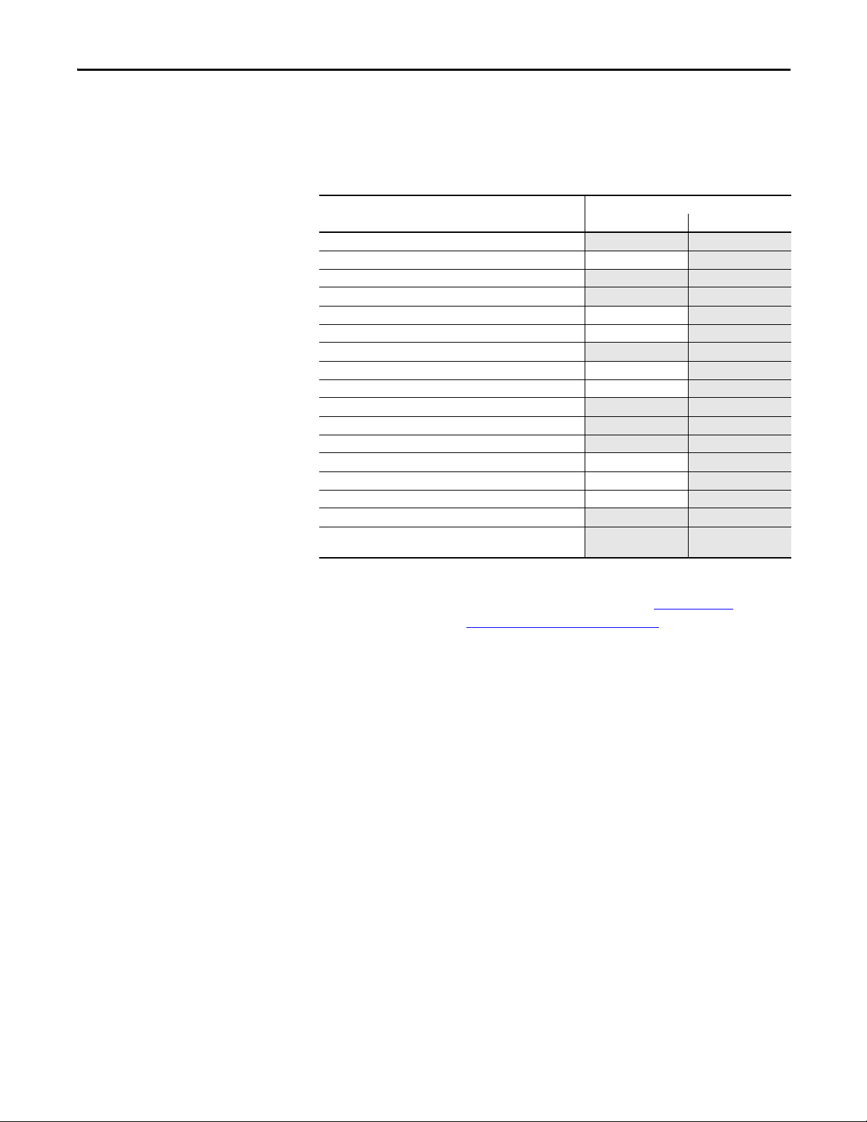
Two lines of 1756 GuardLogix controllers are available. These controllers share
many features, but also have some differences. Ta b l e 1
provides a brief overview of
those differences.
Table 1 - Differences between GuardLogix 5570 and GuardLogix 5560 Controllers
Feature GuardLogix 5570 Controllers
Clock support and backup
used for memory
retention at powerdown
Communication ports
(built-in)
Connections, controller 500 250
Memory, nonvolatile Secure Digital (SD) card CompactFlash card
Status indicators Scrolling status display and LED status indicators LED status indicators
Programming tool • Studio 5000 environment, version 21.00.00
User Manual • Studio 5000 environment: this manual
Safety Reference Manual • Studio 5000 environment: 1756-RM099
(1756-L71S, 1756-L72S, 1756-L73S, 1756-L7SP
1756-L73SXT, 1756-L7SPXT)
Energy Storage Module (ESM) Battery
USB Serial
or later
• RSLogix
• RSLogix 5000 software: 1756-UM020
• RSLogix 5000 software: 1756-RM093
™ 5000 software, version 20.00.00 or
later
GuardLogix 5560 Controllers
(1756-L61S, 1756-L62S,
1756-L63S, 1756-LSP)
• RSLogix 5000 software, version
14.xx.xx
• RSLogix 5000 software, version
16.00.00 or later
1756-UM020
1756-RM093
Rockwell Automation Publication 1756-UM022A-EN-P - November 2012 7
Page 8
Preface
IMPORTANT
The extreme environment GuardLogix controller, catalog numbers
1756-L73SXT and 1756-L7SPXT, provides the same functionality as the
1756-L73S controller, but is designed to withstand temperatures of
-25...70 °C (-13...158 °F).
Logix-XT system components are rated for extreme environmental conditions
only when used properly with other Logix-XT system components. The use of
Logix-XT components with traditional Logix system components nullifies
extreme-environment ratings.
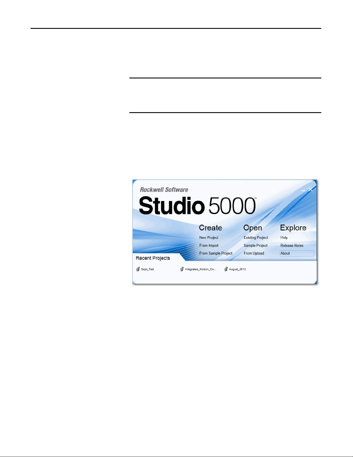
Studio 5000 Environment
The Studio 5000™ Engineering and Design Environment combines engineering
and design elements into a common environment. The first element in the Studio
5000 environment is the Logix Designer application. The Logix Designer
application is the rebranding of RSLogix™ 5000 software and will continue to be
the product to program Logix5000™ controllers for discrete, process, batch,
motion, safety, and drive-based solutions.
The Studio 5000 environment is the foundation for the future of Rockwell
Automation® engineering design tools and capabilities. It is the one place for
design engineers to develop all the elements of their control system.
8 Rockwell Automation Publication 1756-UM022A-EN-P - November 2012
Page 9

Preface
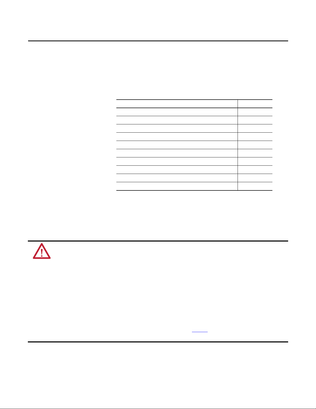
Understanding Terminology
This table defines terms used in this manual.
Table 2 - Terms and Definitions
Abbreviation Full Term Definition
1oo2 One Out of Two Refers to the behavioral design of a multi-processor safety system.
CIP Common Industr ial Protocol A communication protocol designed for industrial automation applications.
CIP Safety Common Industrial Protocol – Safety Certified SIL 3/PLe rated version of CIP.
DC Diagnostic Coverage The ratio of the detected failure rate to the total failure rate.
EN European Norm. The official European standard.
ESM Energy Storage Module Used for clock support and backup for memory retention at powerdown on GuardLogix 5570 controllers.
GSV Get System Value An instruction that retrieves specified controller-status information and places it in a destination tag.
— Multicast The transmission of information from one sender to multiple receivers.
PFD Probability of Failure on Demand The average probability of a system to fail to perform it s design function on demand.
PFH Probability of Failure per Hour The probability of a system to have a dangerous failure occur per hour.
PL Performance Level ISO 13849-1 safety rating.
RPI Requested Packet Interval The expected rate in time for production of data when communicating over a network.
SNN Safety Network Number A unique number that identifies a section of a safety network.
SSV Set System Value An instruction that sets controller system data.
— Standard An object, task, tag, program, or component in your project that is not a safety-related item.
— Unicast The transmission of information from one sender to one receiver.
Rockwell Automation Publication 1756-UM022A-EN-P - November 2012 9
Page 10
Preface
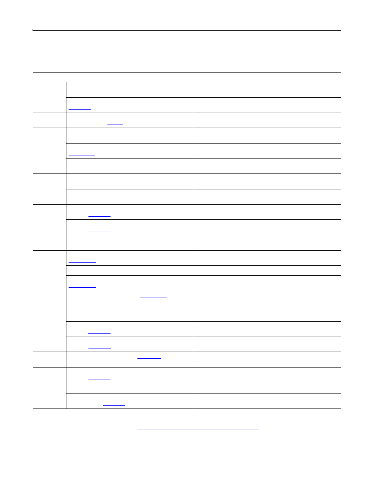
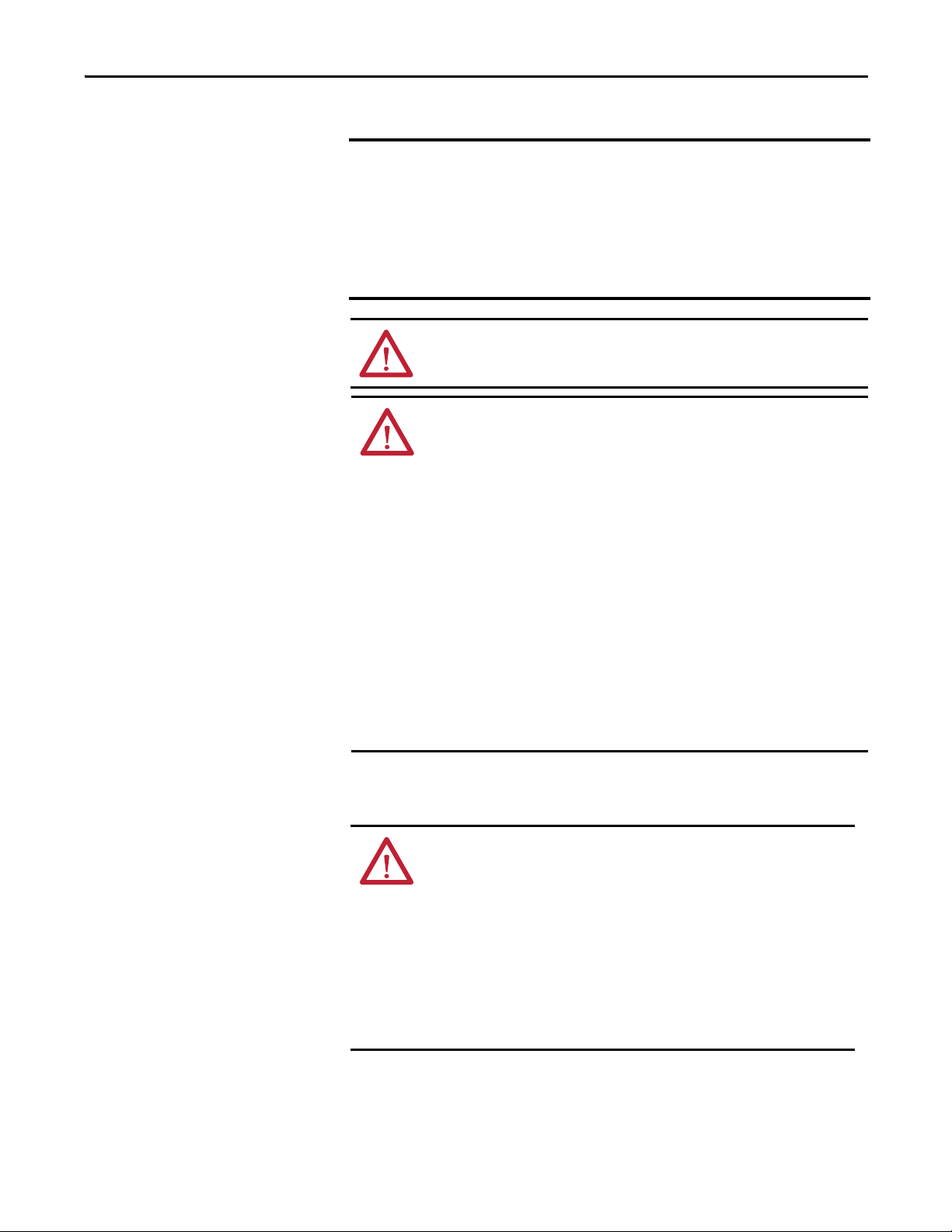
Additional Resources
These documents contain additional information concerning related products
from Rockwell Automation.
Table 3 - Publications Related to GuardLogix Controllers and Systems
Resource Description
(Safety)
Application
requirements
CIP Sync (time
synchronization)
Guard I/O™ Guard I/O DeviceNet Safety Modules User Manual, publication
Hardware
installation
Instructions
(programming)
Motion SERCOS Motion Configuration and Star tup User Manual, publication
Networks
(ControlNet,
DeviceNet
EtherNet/IP)
PhaseManager™ PhaseManager User Manual, publication LOGI X-U M001
Programming
tasks and
procedures
GuardLogix 5570 Controller Systems Safety Reference Manual,
publication 1756-RM099
GuardLogix Controller Systems Safety Reference Manual, publication
1756-RM093
Integrated Architecture and CIP Sync Configuration Application
Technique, publication IA-AT003
1791DS-UM001
Guard I/O EtherNet/IP Safety Modules User Manual, publication
1791ES-UM001
POINT Guard I/O Safety Modules User Manual, publication 1734-UM013
ControlLogix Chassis and Power Supplies Installation Instructions,
publication 1756-IN005
Industrial Automation Wiring and Grounding Guidelines, publication
1770-4.1
GuardLogix Safety Application Instruction Set Reference Manual,
publication 1756-RM095
Logix5000 Controllers General Instructions Reference Manual,
publication 1756-RM003
Logix5000 Controllers Motion Instructions Reference Manual, publication
MOTION-RM002
MOTION-UM001
Motion Coordinated Systems User Manual, publication MOTION-UM002 Details how to create and configure a coordinated motion application system.
CIP Motion Configuration and Startup User Manual, publication
MOTION-UM003
CIP Motion Reference Manual, publication MOTION-RM003
EtherNet/IP Modules in Logix5000 Control Systems User Manual,
publication ENET-UM001
ControlNet Modules in Logix5000 Control Systems User Manual,
publication CNET-UM001
DeviceNet Modules in Logix5000 Control Systems User Manual,
publication DNET-UM004
Logix5000 Controllers Common Procedures Programming Manual,
publication 1756-PM001
Logix5000 Controllers Execution Time and Memory Use Reference
Manual, publication 1756-RM087
Contains detailed requirements for achieving and maintaining SIL 3/PLe with the
GuardLogix 5570 controller system, using the Studio 5000 Logix Designer application.
Contains detailed requirements for achieving and maintaining SIL 3/PLe with the
GuardLogix 5560 or 5570 controller system, using RSLogix 5000 software.
Provides detailed and comprehensive information about how to apply CIP Sync
technology to synchronize clocks in a Logix control system.
Provides information on using Guard I/O DeviceNet Safety modules.
Provides information on using Guard I/O EtherNet/IP Safety modules.
Provides information on installing, configuring, and using POINT Guard I/O™
modules.
Describes how to install and ground ControlLogix® chassis and power supplies.
Provides in-depth information on grounding and wiring programmable controllers
Provides information on the GuardLogix Safety ap plication instruction set.
Provides programmers with details about each available instruction for a Logix5000™
controller.
Provides programmers with details about the motion instructions that are available
for a Logix5000 controller.
Details how to configure a SERCOS motion application system.
Details how to configure a Integrated Motion on EtherNet/IP networks application
system.
Detailed information on axis control modes and attributes for Integrated Motion on
EtherNet/IP networks.
Describes how to configure and operate EtherNet/IP modules in a Logix5000 control
system.
Describes how to configure and operate ControlNet modules in a Logix5000 control
system.
Describes how to configure and operate DeviceNet modules in a Logix5000 control
system.
Provides steps, guidance, and examples for setting up and programming a Logix5000
controller to use equipment phases.
Provides access to the Logix5000 Controllers set of programming manuals, which
cover managing project files, organizing tags, ladder logic programming, testing
routines, creating Add-On Instructions, controller status data, handling faults,
importing and exporting project components and more.
Assists in estimating the memory use and execution time of programmed logic and in
selecting among different programming options.
You can view or download publications at
http://www.rockwellautomation.com/literature
technical documentation, contact your local Allen-Bradley distributor or
Rockwell Automation sales representative.
10 Rockwell Automation Publication 1756-UM022A-EN-P - November 2012
. To order paper copies of
Page 11

System Overview
Top ic Pag e
Safety Application Requirements 11
Distinguishing between Standard and Safety Components 12
Controller Data Flow Capabilities 13
Selecting System Hardware 14
Selecting Safety I/O Modules 15
Selecting Communication Networks 16
Programming Requirements 16
Chapter 1
Safety Application Requirements
The GuardLogix 5570 controller system is certified for use in safety applications
up to and including Safety Integrity Level (SIL) 3 and Performance Level (e) in
which the de-energized state is the safe state. Safety application requirements
include evaluating probability of failure rates (PFD and PFH), system
reaction-time settings, and functional-verification tests that fulfill SIL 3/PLe
criteria.
GuardLogix-based SIL 3/PLe safety applications require the use of at least one
safety network number (SNN) and a safety task signature. Both affect controller
and I/O configuration and network communication.
For SIL 3 and PLe safety system requirements, including functional validation
test intervals, system reaction time, and PFD/PFH calculations, refer to the
GuardLogix 5570 Controller Systems Safety Reference Manual, publication
1756-RM099
operating a GuardLogix SIL 3, PLe safety system.
. You must read, understand, and fulfill these requirements prior to
Safety Network Number
The safety network number (SNN) must be a unique number that identifies
safety subnets. Each safety subnet that the controller uses for safety
communication must have a unique SNN. Each CIP Safety device must also be
configured with the safety subnet’s SNN. The SNN can be assigned
automatically or manually.
For information on assigning the SNN, see Managing the Safety Network
Number (SNN) on page 43.
Rockwell Automation Publication 1756-UM022A-EN-P - November 2012 11
Page 12

Chapter 1 System Overview
Safety Task Signature
The safety task signature consists of an ID number, date, and time that uniquely
identifies the safety portion of a project. This includes safety logic, data, and
configuration. The GuardLogix system uses the safety task signature to
determine the project’s integrity and to let you verify that the correct project is
downloaded to the target controller. Creating, recording, and verifying the safety
task signature is a mandatory part of the safety-application development process.
Distinguishing between Standard and Safety Components
See Generate a Safety Task Signature
Slots of a GuardLogix system chassis not used by the safety function may be
populated with other ControlLogix modules that are certified to the Low
Voltage and EMC Directives. Refer to http://
find the CE certificate for the Programmable Control–ControlLogix Product
Family and determine which modules are certified.
You must create and document a clear, logical, and visible distinction between the
safety and standard portions of the controller project. To aid in creating this
distinction, the Logix Designer application features safety identification icons to
identify the safety task, safety programs, safety routines, and safety components.
In addition, the Logix Designer application uses a safety class attribute that is
visible whenever safety task, safety programs, safety routine, safety tag, or safety
Add-On Instruction properties are displayed.
The controller does not allow writes to safety tag data from external HMI devices
or via message instructions from peer controllers. The Logix Designer
application can write safety tags when the GuardLogix controller is
safety-unlocked, does not have a safety task signature, and is operating without
safety faults.
on page 96 for more information.
www.ab.com/certification/ce to
The ControlLogix Controllers User Manual, publication 1756-UM001
provides information on using ControlLogix devices in standard (non safety)
applications.
HMI Devices
HMI devices can be used with GuardLogix controllers. HMI devices can access
standard tags just as with a standard controller. However, HMI devices cannot
write to safety tags; safety tags are read-only for HMI devices.
12 Rockwell Automation Publication 1756-UM022A-EN-P - November 2012
,
Page 13
System Overview Chapter 1
IMPORTANT
GuardLogix Controller
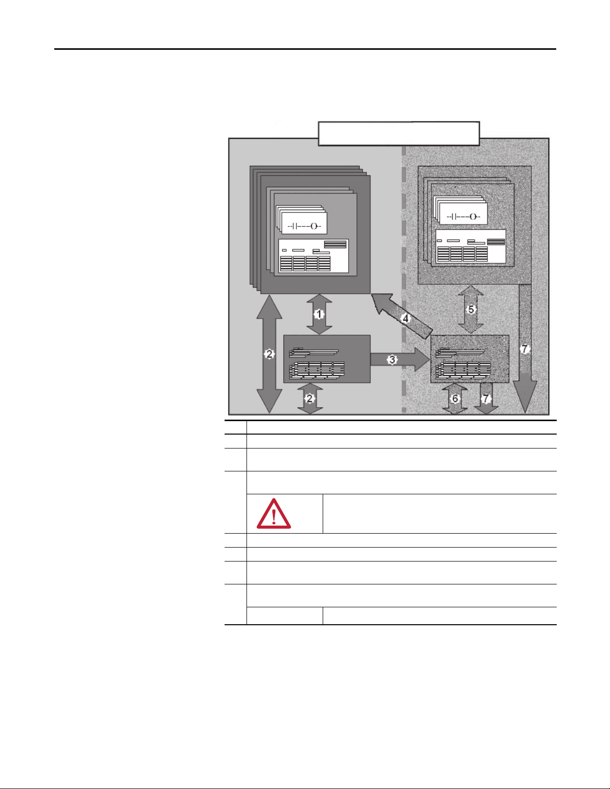
Controller Data Flow Capabilities
This illustration explains the standard and safety data-flow capabilities of the
GuardLogix controller.
Figure 1 - Data Flow Capabilities
Standard Safety
Standard Tasks
Standard Programs
Standard Routines
Program Data
Controller Standard Tags
Safety Task
Safety Programs
Safety Routines
Program Safety Data
Controller Safety Tags
No. Description
1 Standard tags and logic behave the same way they do in the standard Logix platform.
2 Standard tag data, program- or controller-scoped, can be exchanged with external HMI devices, personal
computers, and other controllers.
3 GuardLogix controllers are integrated controllers with the ability to move (map) standard tag data into safety
tags for use within the safety task.
ATT EN TI ON : This data must not be used to directly control a SIL 3/PLe
output.
4 Controller-scoped safety tags can be read directly by standa rd logic.
5 Safety tags can be read or written by safety logic.
6 Safety tags can be exchanged between safety controllers over Ethernet or ControlNet networks, including 1756
and 1768 GuardLogix controllers.
7 Safety tag data, program- or controller-scoped, can be read by external devices, such as HMI devices, personal
computers, or other standard controllers.
Once this data is read, it is considered standard data, not SIL 3/PLe data.
Rockwell Automation Publication 1756-UM022A-EN-P - November 2012 13
Page 14
Chapter 1 System Overview
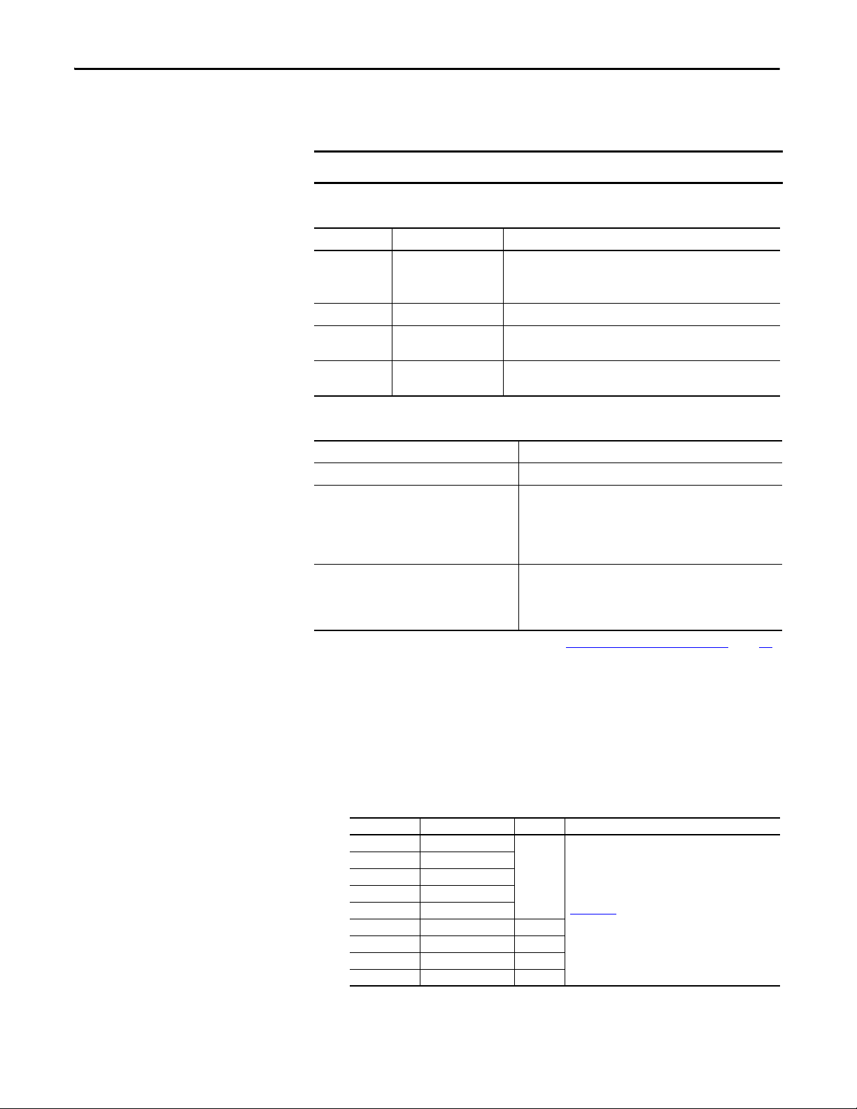
Selecting System Hardware
The GuardLogix system supports SIL 3 and PLe safety applications. The
GuardLogix controller is made up of a primary controller and a safety partner
that function together in a 1oo2 architecture. Ta b l e 4
lists catalog numbers for
primary controllers and safety partners.
The safety partner must be installed in the slot immediately to the right of the
primary controller. The firmware major and minor revisions of the primary
controller and safety partner must match exactly to establish the control
partnership required for safety applications.
Table 4 - Primary Controller and Corresponding Safety Partner Catalog Numbers
Primary Controller Safety Partner
1756-L71S, 1756-L72S, 1756-L73S 1756-L7SP
1756-L73SXT 1756-L7SPXT
Primary Controller
The primary controller is the processor that performs standard and safety
functions and communicates with the safety partner for safety-related functions
in the GuardLogix control system. Standard functions include the following:
• I/O control
• Logic
• Timing
• Counting
• Report generation
• Communication
• Arithmetic computations
• Data file manipulation
The primary controller consists of a central processor, I/O interface, and
memory.
Table 5 - Memory Capacity
Cat. No.
1756-L71S 2MB 1 MB
1756-L72S 4 MB 2 MB
1756-L73S,1756-L73SXT 8 MB 4 MB
Standard Tasks and Components Safety Task and Components
User Memory (RAM capacity)
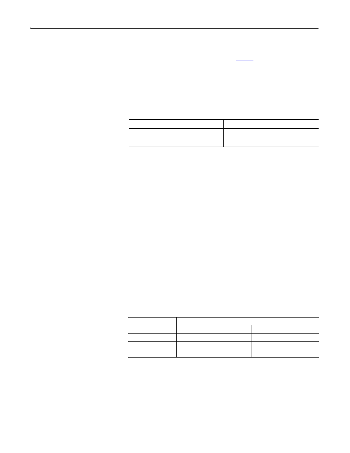
A three-position keyswitch on the front of the primary controller governs the
controller operational modes. The following modes are available:
• RUN
• PROGram
• REMote - this software-enabled mode can be Program, Run, or Test
14 Rockwell Automation Publication 1756-UM022A-EN-P - November 2012
Page 15
System Overview Chapter 1
OKFORCE SDRUN
Logix557x
R
U
N
R
E
M
P
R
O
G
1756-L7xS
Figure 2 - Keyswitch Positions
Safety Partner
The safety partner is a coprocessor that provides an isolated second channel
(redundancy) for safety-related functions in the system.
The safety partner does not have a keyswitch or communication port. Its
configuration and operation are controlled by the primary controller.
Selecting Safety I/O Modules
Chassis
The ControlLogix chassis provides physical connections between modules and
the GuardLogix controller.
Power Supply
The ControlLogix power supplies listed on page 23 are suitable for use in SIL 3
applications. No extra configuration or wiring is required for SIL 3 operation of
the power supplies.
Safety input and output devices can be connected to CIP Safety I/O on
DeviceNet or EtherNet/IP networks, allowing output devices to be controlled by
a GuardLogix controller system via DeviceNet or EtherNet/IP communication.
For the most up-to-date information on available CIP Safety I/O catalog
numbers, certified series, and firmware revisions, see
http://www.ab.com/certification/safety
.
Rockwell Automation Publication 1756-UM022A-EN-P - November 2012 15
Page 16
Chapter 1 System Overview
Selecting Communication Networks
The GuardLogix controller supports communication that lets it do the
following:
• Distribute and control Safety I/O on DeviceNet or EtherNet/IP networks
• Distribute and control remote Safety I/O on DeviceNet, EtherNet/IP, or
ControlNet networks
• Produce and consume safety tag data between 1756 and 1768 GuardLogix
controllers across EtherNet/IP or ControlNet networks or within the
same ControlLogix chassis
• Distribute and control standard I/O on EtherNet, ControlNet, or
DeviceNet networks
Use these communication modules to provide an interface between GuardLogix
controllers and network devices.
Table 6 - Communication Modules
To interface between Use this module Refer to these installation
The GuardLogix controller and DeviceNet devices 1756-DNB DNET-IN001
1756-ENBT
The GuardLogix controller and EtherNet/IP devices
Controllers on the ControlNet network
1756-EN2T
1756-EN2F
1756-EN2TR, 1756-EN3TR
1756-EN2TXT
1756-CN2, 1756-CN2R
1756-CN2RXT
instructions
ENET-IN002
CNET-IN005
Programming Requirements
The GuardLogix controller can connect to the Logix Designer application via a
USB connection, an EtherNet module, or a ControlNet module.
See the Additional Resources
on page 10 for more information on using network
communication modules.
Use Ta b l e 7 to identify the programming tool and the versions for use with your
GuardLogix 5570 controllers.
Table 7 - Software Versi ons
Cat. No. Studio 5000 Environment RSLogix 5000 Software
1756-L71S, 1756-L72S,
1756-L73S, 1756-L73SXT
(1) For information on using a GuardLogix controller with RSLog ix 5000 sof tware, refer to GuardLogix Co ntrollers Us er Manual,
publication 1756-UM020
21.00.00 or later 20.00.00 or later 2.59 or later
and GuardLogix Controller Systems Safety Reference Manual, publication 1756-RM093.
Vers ion
(1)
RSLinx® Classic
Software Version
16 Rockwell Automation Publication 1756-UM022A-EN-P - November 2012
Page 17
System Overview Chapter 1
Safety routines include safety instructions, which are a subset of the standard
ladder logic instruction set, and safety application instructions. Programs
scheduled under the safety task support only ladder logic.
Table 8 - Supported Features
Featu re
Add-On Instruc tions
Alarms and events X
Controller logging
Data Access Control
Equipment phase routines X
Event tas ks
Firmware Sup ervisor
Function block diagrams (FBD) X
Integrated motion
Ladder logic
Language switching X X
Memory card
Online import and export of program components
Sequential function chart (SFC) routines X
Structured text
Unicast connections for produced and consumed safety tags
Unicast connections for safety I/O modules on EtherNet/IP
networks
Studio 5000 Logix Designer Application
Sa fety Task Sta ndar d Task
X X
X X
X X
X
X X
X
X X
X X
X
X
X X
X X
For information on using these features, refer to the Logix5000 Controllers
Common Procedures Programming Manual, publication 1756-PM001
publications listed in the Additional Resources
on page 10, and online help.
, the
Rockwell Automation Publication 1756-UM022A-EN-P - November 2012 17
Page 18

Chapter 1 System Overview
Notes:
18 Rockwell Automation Publication 1756-UM022A-EN-P - November 2012
Page 19
Install the Controller
Top ic Pag e
Precautions 19
Make Sure That You Have All of the Components 22
Install a Chassis and Power Supply 22
Install the Controller into the Chassis 23
Insert or Remove a Memory Card 24
Make Communication Connections 27
Update the Controller 29
Choose the Operating Mode of the Controller 31
Uninstall an Energy Storage Module (ESM) 33
Install an Energy Storage Module (ESM) 34
Chapter 2
Precautions
Read and follow these precautions for use.
Environment and Enclosure Information
ATTENTION: This equipment is intended for use in a Pollution Degree 2 industrial environment, in overvoltage Category II
applications (as defined in IEC 60664-1), at altitudes up to 2000 m (6562 ft) without derating.
This equipment is not intended for use in residential environments and may not provide adequate protection to radio
communication services in such environments.
This equipment is supplied as open-type equipment. It must be mounted within an enclosure that is suitably designed for those
specific environmental conditions that will be present and appropriately designed to prevent personal injury resulting from
accessibility to live parts. The enclosure must have suitable flame-retardant properties to prevent or minimize the spread of
flame, complying with a flame spread rating of 5VA or be approved for the application if non-metallic. The interior of the
enclosure must be accessible only by the use of a tool. Subsequent sections of this publication may contain additional
information regarding specific enclosure type ratings that are required to comply with certain product safety certifications.
In addition to this publication, see the following:
• Industrial Automation Wiring and Grounding Guidelines, publication 1770-4.1
• NEMA Standard 250 and IEC 60529, as applicable, for explanations of the degrees of protection provided by enclosure
, for additional installation requirements
Rockwell Automation Publication 1756-UM022A-EN-P - November 2012 19
Page 20

Chapter 2 Install the Controller
Programmable Electronic Systems (PES)
AT TE NT IO N: Personnel responsible for the application of safety-related
Programmable Electronic Systems (PES) shall be aware of the safety
requirements in the application of the system and shall be trained in using
the system.
Removal and Insertion Under Power (RIUP)
WARNING: When you insert or remove the module while backplane power is
on, an electrical arc can occur. This could cause an explosion in hazardous
location installations.
Be sure that power is removed or the area is nonhazardous before proceeding.
Repeated electrical arcing causes excessive wear to contacts on both the module
and its mating connector. Worn contacts may create electrical resistance that
can affect module operation.
North American Hazardous Location Approval
The following information applies when operating this
equipment in hazardous locations.
Products marked "CL I, DIV 2, GP A, B, C, D" are suitable for use in Class
I Division 2 Groups A, B, C, D, Hazardous Locations and nonhazardous
locations only. Each product is supplied with markings on the rating
nameplate indicating the hazardous location temperature code.
When combining products within a system, the most adverse
temperature code (lowest "T" number) may be used to help
determine the overall temperature code of the system. Combinations
of equipment in your system are subject to investigation by the local
Authority Having Jurisdiction at the time of installation.
WARNING: EXPLOSION HAZARD
• Do not disconnect equipment unless power has
been removed or the area is known to be
nonhazardous.
• Do not disconnect connections to this equipment
unless power has been removed or the area is
known to be nonhazardous. Secure any external
connections that mate to this equipment by using
screws, sliding latches, threaded connectors, or
other means provided with this product.
• Substitution of components may impair suitability
for Class I, Division 2.
• If this product contains batteries, they must only be
changed in an area known to be nonhazardous.
Informations sur l'utilisation de cet équipement en
environnements dangereux.
Les produits marqués "CL I, DIV 2, GP A, B, C, D" ne conviennent qu'à
une utilisation en environnements de Classe I Division 2 Groupes A, B,
C, D dangereux et non dangereux. Chaque produit est livré avec des
marquages sur sa plaque d'identification qui indiquent le code de
température pour les environnements dangereux. Lorsque plusieurs
produits sont combinés dans un système, le code de température le
plus défavorable (code de température le plus faible) peut être utilisé
pour déterminer le code de température global du système. Les
combinaisons d'équipements dans le système sont sujettes à
inspection par les autorités locales qualifiées au moment de
l'installation.
AVERTISSEMENT: RISQUE D’EXPLOSION
• Couper le courant ou s'assurer que l'environnement
est classé non dangereux avant de débrancher
l'équipement.
• Couper le courant ou s'assurer que l'environnement
est classé non dangereux avant de débrancher les
connecteurs. Fixer tous les connecteurs externes
reliés à cet équipement à l'aide de vis, loquets
coulissants, connecteurs filetés ou autres moyens
fournis avec ce produit.
• La substitution de composants peut rendre cet
équipement inadapté à une utilisation en
environnement de Classe I, Division 2.
• S'assurer que l'environnement est classé non
dangereux avant de changer les piles.
20 Rockwell Automation Publication 1756-UM022A-EN-P - November 2012
Page 21
Install the Controller Chapter 2
European Hazardous Location Approval
The following applies when the product bears the Ex Marking.
This equipment is intended for use in potentially explosive atmospheres as defined by
European Union Directive 94/9/EC and has been found to comply with the Essential Health and
Safety Requirements relating to the design and construction of Category 3 equipment intended
for use in Zone 2 potentially explosive atmospheres, given in Annex II to this Directive.
Compliance with the Essential Health and Safety Requirements has been assured by
compliance with EN 60079-15 and EN 60079-0.
ATTENTION: This equipment is not resistant to sunlight or other sources of
UV radiation.
WARNING:
• This equipment shall be mounted in an ATEX certified enclosure with a
minimum ingress protection rating of at least IP54 (as defined in IEC60529)
and used in an environment of not more than Pollution Degree 2 (as defined
in IEC 60664-1) when applied in Zone 2 environments. The enclosure must
utilize a tool removable cover or door.
• This equipment shall be used within its specified ratings defined by
Rockwell Automation.
• Provision shall be made to prevent the rated voltage from being exceeded by
transient disturbances of more than 140% of the rated voltage when
applied in Zone 2 environments.
• This equipment must be used only with ATEX-certified Rockwell Automation
backplanes.
• Secure any external connections that mate to this equipment by using
screws, sliding latches, threaded connectors, or other means provided with
this product.
• Do not disconnect equipment unless power has been removed or the area is
known to be nonhazardous.
Prevent Electrostatic Discharge
ATT EN TI ON : This equipment is sensitive to electrostatic discharge, which
can cause internal damage and affect normal operation. Follow these
guidelines when you handle this equipment:
• Touch a grounded object to discharge potential static.
• Wear an approved grounding wriststrap.
• Do not touch connectors or pins on component boards.
• Do not touch circuit components inside the equipment.
• Use a static-safe workstation, if available.
• Store the equipment in appropriate static-safe packaging when not in
use.
Rockwell Automation Publication 1756-UM022A-EN-P - November 2012 21
Page 22
Chapter 2 Install the Controller
IMPORTANT
Make Sure That You Have All of the Components
Before you begin, check to make sure you have all of the components you will
need.
You must use a primary controller and a safety partner to achieve SIL 3/PLe.
These parts are included with the primary controller and safety partner.
Cat. No. Description Ships with
1756-L71S
1756-L72S
1756-L73S
1756-L7SP Safety partner • 1756-SPESMNSE energy storage module (ESM)
1756-L73SXT Extreme temperature
1756-L7SPXT Extreme temperature
Primary controller • 1756-ESMCAP capacitor-based energy storage module (ESM)
primary controller
safety partner
• 1784-SD1 Secure Digital (SD) memory card, 1 GB
• 1747-KY key
• 1756-ESMCAPXT capacitor-based energy storage module (ESM)
• 1747-KY key
• 1756-SPESMNSEXT capacitor-based energy storage module (ESM)
The following optional equipment may be used.
If your application requires Then use this part
Nonvolatile memory 1784-SD1 (1 GB) or 1784-SD2 (2 GB)
That the installed ESM deplete its residual stored
energy to 200 μJ or less before transporting it into
or out of your application
ESM that secures the controller by preventing the
USB connection and SD card use
(1)
(1)
1756-ESMNSE for the primary controller
1756-SPESMNSE for the safety partner
This ESM does not have WallClockTime backup power.
Additionally, you can use this ESM with a 1756-L73S (8 MB) or
smaller memory sized controller only.
1756-ESMNRM for the primary controller
1756-SPESMNRM for the safety partner
This ESM provides your application an enhanced degree of
security.
(2)
(3)
Install a Chassis and Power Supply
(1) For information about the hold-up time of the ESMs, see the section Estimate the ESM Support of the WallClockTime on page 11 3.
(2) For extreme temperature primary controller and safety partner use 1756-ESMNSEXT and 17 56-SPESMNSEXT respectively.
(3) For extreme temperature primary controller and safety partner use 1756-ESMNRMXT and 17 56-SPESMNRMXT respectively
Before you install a controller, you need to install a chassis and power supply.
1. Install a ControlLogix chassis according to the corresponding installation
instructions.
Cat. No. Available Slots Series Refer to These Installation Instructions
1756-A4 4
1756-A7 7
1756-A10 10
1756-A13 13
1756-A17 17
1756-A4LXT 4 B
1756-A5XT 5 B
1756-A7XT 7 B
1756-A7LXT 7 B
B
1756-IN005
Extreme environment (XT) controllers require an XT chassis.
22 Rockwell Automation Publication 1756-UM022A-EN-P - November 2012
Page 23
Install the Controller Chapter 2
IMPORTANT
12
2. Install a ControlLogix power supply according to the corresponding
installation instructions.
Install the Controller into the Chassis
Cat. No. Description Series Refer to These Installation
1756-PA72 Power supply, AC
1756-PB72 Power supply, DC
1756-PA75 Power supply, AC
1756-PB75 Power supply, DC
1756-PAXT XT power supply, AC
1756-PBXT XT power supply, DC
C
B
B
Instructions
1756-IN005
Extreme environment (XT) controllers require an XT power supply.
You can install or remove a controller while chassis power is on and the system is
operating.
WARNING: When you insert or remove the module while backplane
power is on, an electrical arc can occur. This could cause an explosion in
hazardous location installations.
Be sure that power is removed or the area is nonhazardous before
proceeding. Repeated electrical arcing causes excessive wear to contacts on
both the module and its mating connector. Worn contact may create
electrical resistance that can affect module operation.
The ESM begins charging when one of these actions occurs:
• The controller and ESM are installed into a powered chassis.
• Power is applied to the chassis that contains a controller with the ESM
installed.
• An ESM is installed into a powered controller.
After power is applied, the ESM charges for up to two minutes as indicated by
CHRG or ESM Charging on the status display.
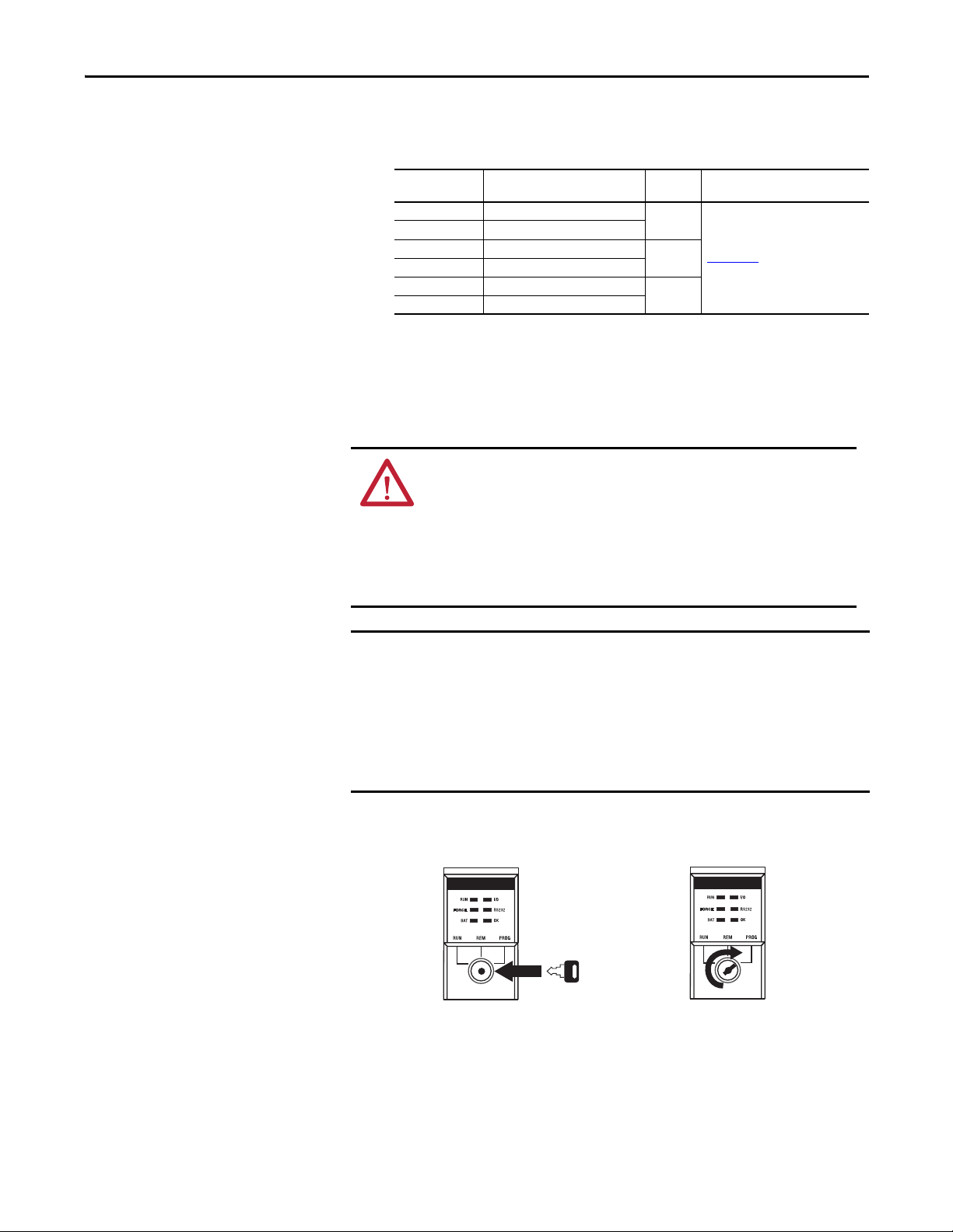
1. Insert the key into the primary controller.
2. Turn the key to the PROG position.
The safety partner does not have a keyswitch.
Rockwell Automation Publication 1756-UM022A-EN-P - November 2012 23
Page 24
Chapter 2 Install the Controller
IMPORTANT
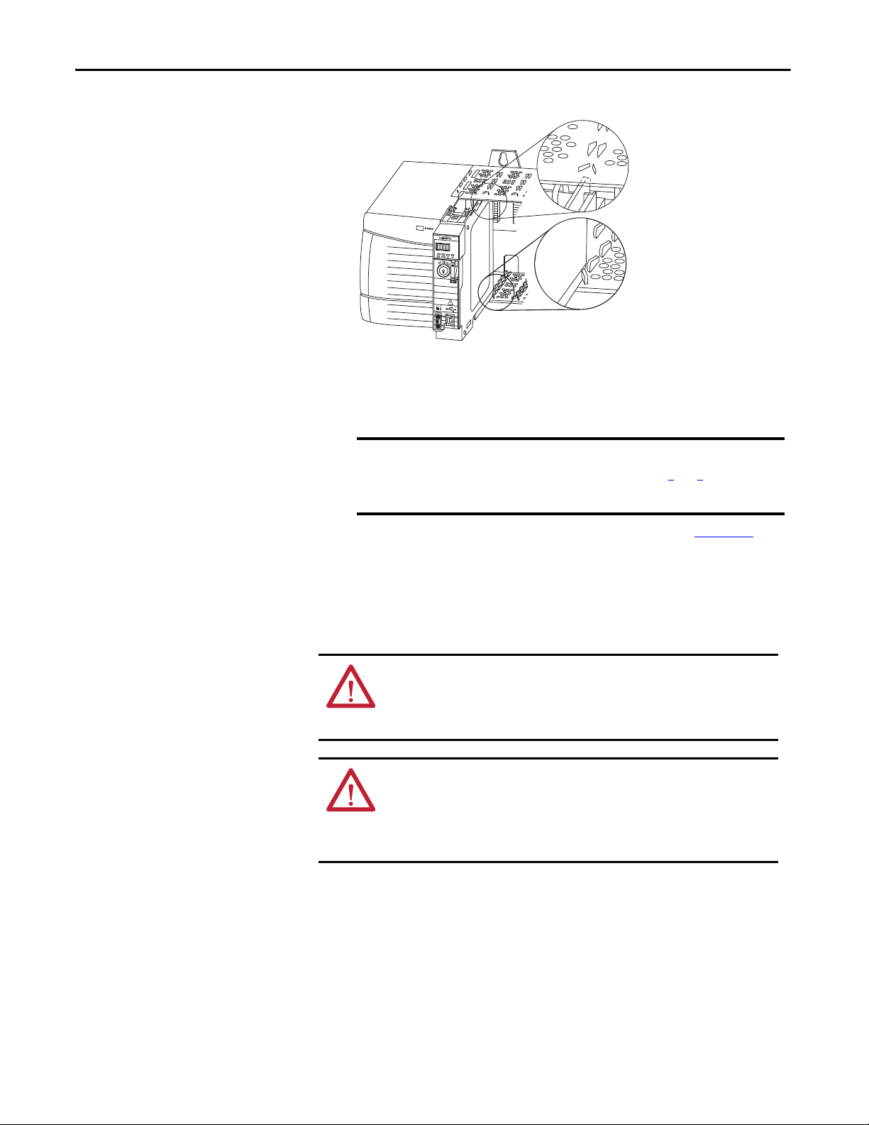
3. Align the circuit board with the top and bottom guides in the chassis.
4. Slide the controller into the chassis.
The controller is fully installed when it is flush with the power supply or
other installed modules and the top and bottom latches are engaged.
You must install the safety partner in the slot immediately to the
right of the primary controller. Follow steps 3
the safety partner.
and 4 above to install
Insert or Remove a Memory Card
After you have inserted the controller into the chassis, see Chapter 9
information on interpreting the status indicators on the primary controller
and safety partner.
WARNING: When you insert or remove the memory card when power is
on, an electrical arc can occur. This could cause an explosion in hazardous
location installations. Be sure that power is removed or the area is
nonhazardous before proceeding.
AT TE NT IO N: If you are not sure of the contents of the memory card,
before you install the card, turn the keyswitch of the controller to the
PROG position. Depending on the contents of the card, a power cycle or
fault could cause the card to load a different project or operating system
into the controller.
The controller ships with an SD card installed. We recommend that you leave an
SD card installed.
for
24 Rockwell Automation Publication 1756-UM022A-EN-P - November 2012
Page 25
Remove the SD Card
IMPORTANT
Logix 55xx
RUN
FORCE
SD
OK
32015-M
Logix 55xx
RUN
FORCE
SD
OK
32004-M
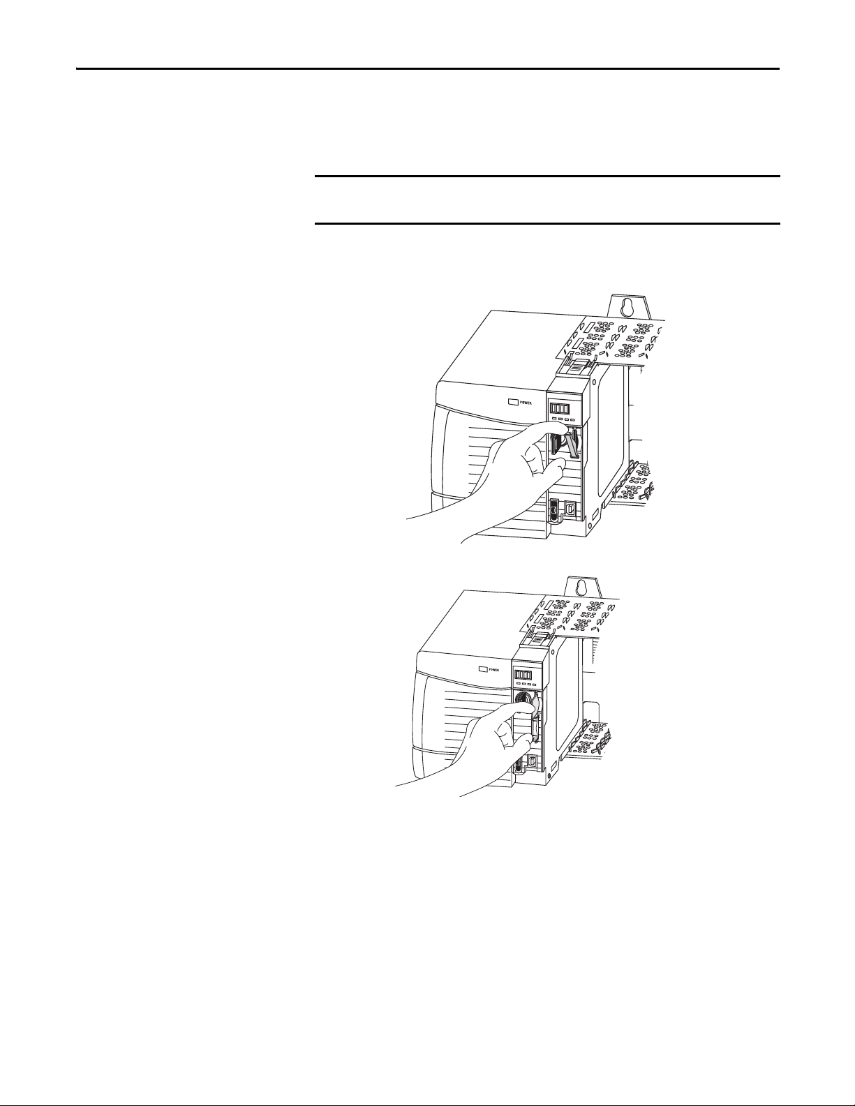
If you want to remove the SD card, follow these steps.
Verify that the SD card status indicator is off and that the card is not in use
before removing it.
1. Turn the keyswitch to the PROG position.
2. Open the door to access the SD card.
Install the Controller Chapter 2
3. Press and release the SD card to eject it.
4. Remove the SD card and close the door.
Rockwell Automation Publication 1756-UM022A-EN-P - November 2012 25
Page 26
Chapter 2 Install the Controller
Unlocked
Locked
32005-M
Logix 55xx
RUN
FORCE
SD
OK
Logix 55xx
RUN
FORCE
SD
OK
32004-M
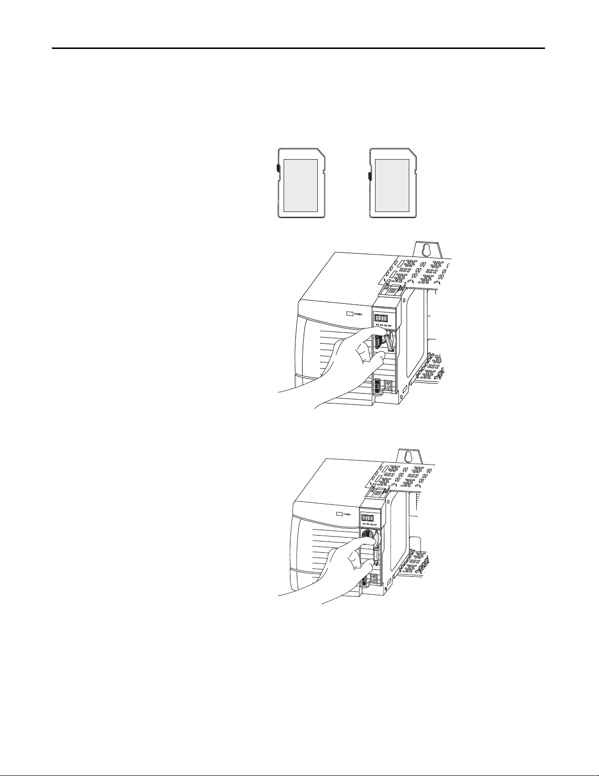
Install the SD Card
Follow these steps to install the SD card.
1. Verify that the SD card is locked or unlocked according to your preference.
2. Open the door for the SD card.
3. Insert the SD card into the SD card slot.
4. Gently press the card until it clicks into place.
26 Rockwell Automation Publication 1756-UM022A-EN-P - November 2012
Page 27
5. Close the SD card door.
Logix 55xx
RUN
FORCE
SD
OK
32006-M
Logix 55xx
RUN
FORCE
SD
OK
32007-M
Install the Controller Chapter 2
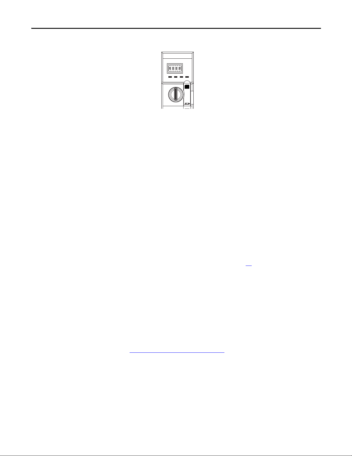
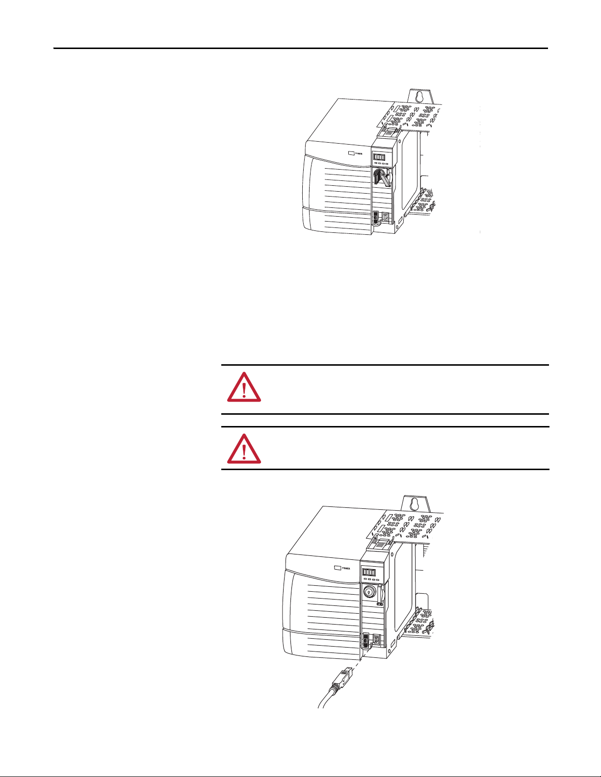
Make Communication Connections
The controller has a USB port that uses a Type B receptacle. The port is USB 2.0compatible and runs at 12 M.
To use the USB port of the controller, you must have RSLinx software, version
2.59 or later, installed on your workstation. Use a USB cable to connect your
workstation to the USB port. With this connection, you can upgrade firmware
and download programs to the controller directly from your workstation.
ATTENTION: The USB port is intended for temporary local programming
purposes only and not intended for permanent connection.
The USB cable must not exceed 3.0 m (9.84 ft) and must not contain hubs.
WARNING: Do not use the USB port in hazardous locations.
Figure 3 - USB Connection
Rockwell Automation Publication 1756-UM022A-EN-P - November 2012 27
Page 28
Chapter 2 Install the Controller
TIP
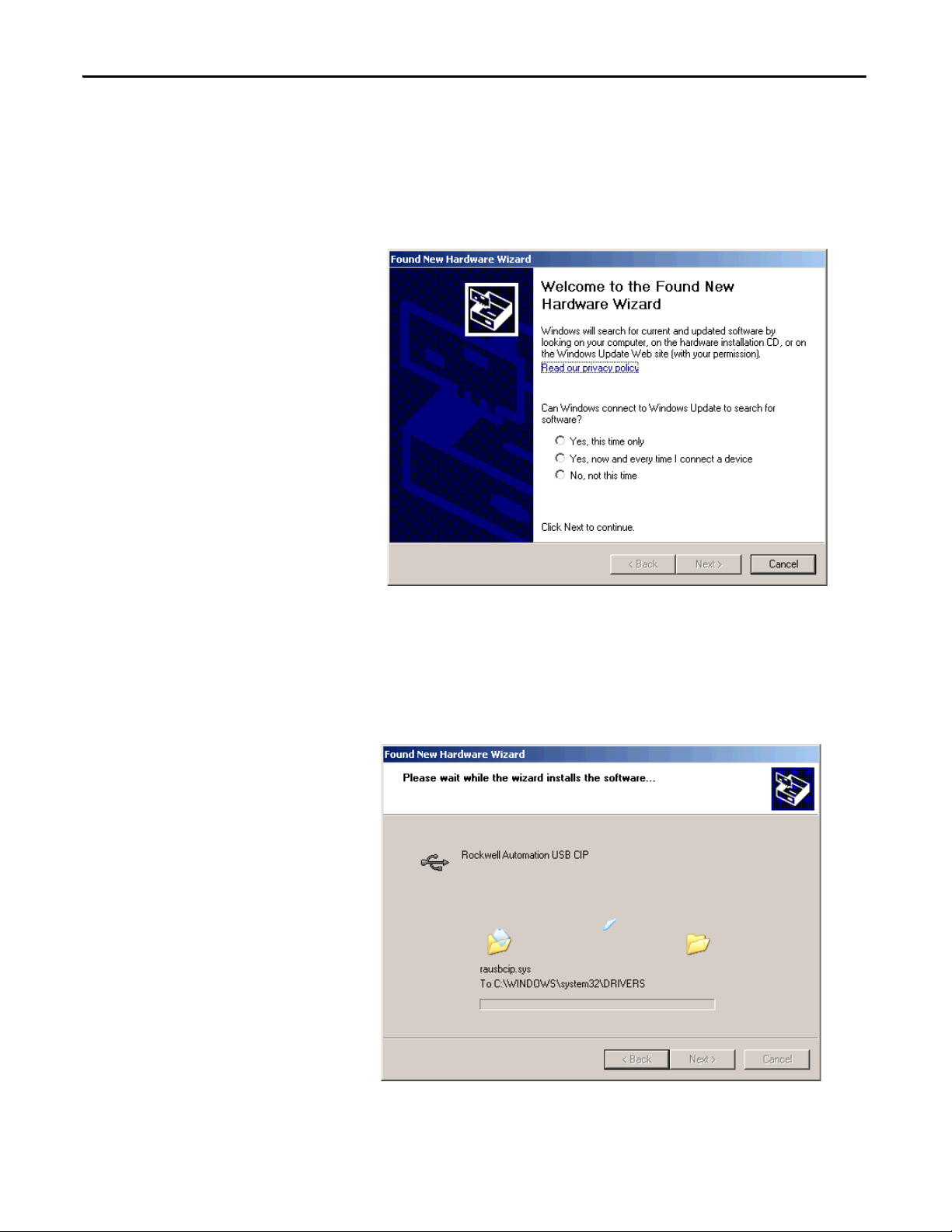
To configure RSLinx software to use a USB port, you need to first set up a USB
driver. To set up a USB driver, perform this procedure.
1. Connect your controller and workstation by using a USB cable.
2. On the Found New Hardware Wizard dialog box, click any of the
Windows Update connection options and click Next.
If the software for the USB driver is not found and the installation is canceled,
verify that you have installed RSLinx Classic software, version 2.59 or later.
3. Click Install the software automatically (Recommended) and click Next.
The software is installed.
4. Click Finish to set up your USB driver.
28 Rockwell Automation Publication 1756-UM022A-EN-P - November 2012
Page 29
Install the Controller Chapter 2
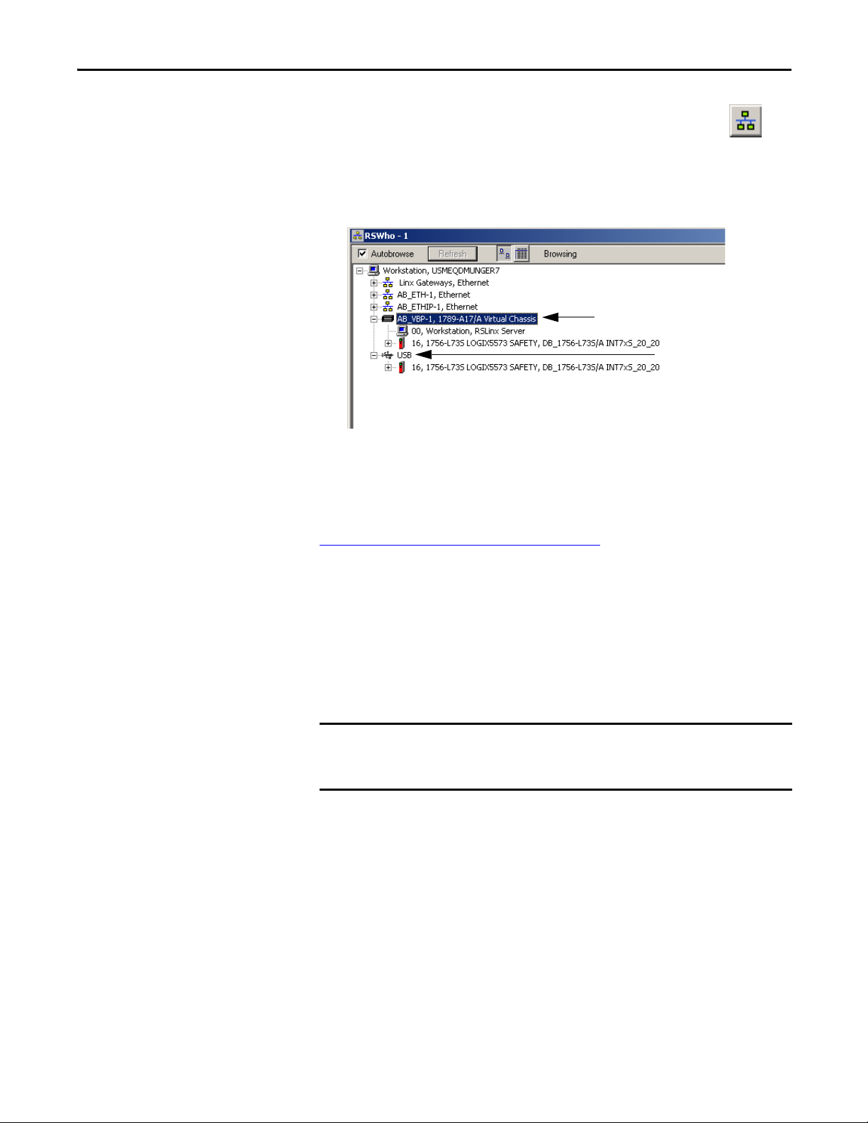
Virtual Chassis Driver
USB Port Driver
IMPORTANT
5. To browse to your controller in RSLinx software, click RSWho .
In the RSLinx Workstation organizer, your controller appears under two
different drivers, a virtual chassis and the USB port. You can use either driver to
browse to your controller.
Update the Controller
The controllers ship without firmware. Controller firmware is packaged with
Studio 5000 environment. In addition, controller firmware is also available for
download from the Rockwell Automation Technical Support website at:
http://www.rockwellautomation.com/support/
You can upgrade your firmware by using either ControlFLASH™ software or by
using the AutoFlash feature of the Logix Designer application.
.
Using ControlFLASH Software to Update Firmware
The safety partner updates automatically when the primary controller is updated.
If the SD card is locked and the stored project’s Load Image option is set to
On Power Up, the controller firmware is not updated as a result of these steps.
Any previously-stored firmware and projects are loaded instead.
1. Verify that the appropriate network connection is made and the network
driver has been configured in RSLinx software.
2. Start ControlFLASH software.
3. Choose Next.
4. Select the catalog number of the controller and click Next.
5. Expand the network until you see the controller.
Rockwell Automation Publication 1756-UM022A-EN-P - November 2012 29
Page 30
Chapter 2 Install the Controller
IMPORTANT
TIP
42900
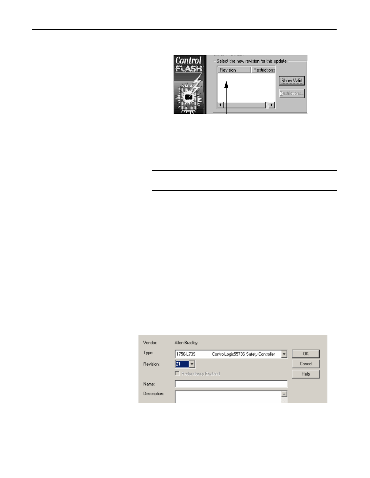
6. Select the controller and click Next.
7. Select the revision level to which you want to update the controller and
click Next.
8. To start the update of the controller, click Finish and then click Yes.
After the controller is updated, the status dialog box displays ‘Update
complete’.
Allow the firmware update to fully complete before cycling power or
otherwise interrupting the upgrade.
If the ControlFLASH update of the controller is interrupted, the
controller reverts to boot firmware, that is firmware revision 1.xxx.
9. Click OK.
10. Close ControlFLASH software.
Using AutoFlash to Update Firmware
To update your controller firmware with the AutoFlash feature, follow these
steps.
1. Verify that the appropriate network connection is made and your network
driver is configured in RSLinx software.
2. Use the Logix Designer application to create a controller project at the
version you need.
30 Rockwell Automation Publication 1756-UM022A-EN-P - November 2012
Page 31

Install the Controller Chapter 2
3. Click RSWho to specify the controller path.
4. Select your controller and click Update Firmware.
5. Select the firmware revision you want.
6. Click Update.
7. Click Yes.
Allow the firmware update to complete without interruption. When the
firmware upgrade is complete, the Who Active dialog box opens. You may
complete other tasks in the Logix Designer application.
Choose the Operating Mode of the Controller
Use this table as a reference when determining your controller Operation mode.
Table 9 - Controller Operation Modes
Select one of these modes
If you want to
Turn outputs to the state commanded by the logic of the
project
Turn outputs to their configured state for Program mode XX X
Execute (scan) tasks XXX
Change the mode of the controller through software XX X
Download a project XX X X
Schedule a ControlNet network XX
While online, edit the project XX X X
Send messages XXX
Send and receive data in response to a message from
another controller
Produce and consume tags XXX X X
Run
XX
XXX X X
Remote
Run Test Program
Program
Use the Keyswitch to Change the Operation Mode
The keyswitch on the front of the controller can be used to change the controller
to one of these modes:
• Program (PROG)
• Remote (REM)
• Run (RUN)
Rockwell Automation Publication 1756-UM022A-EN-P - November 2012 31
Page 32

Chapter 2 Install the Controller
TIP
OKFORCE SDRUN
Logix557x
R
U
N
R
E
M
P
R
O
G
Figure 4 - Controller Keyswitch
Use the Logix Designer Application to Change the Operation Mode
Depending on the mode of the controller you specify by using the keyswitch, you
can change the operation mode of the controller by using the Logix Designer
application.
After you are online with the controller and the controller keyswitch is set to
Remote (REM or the center position), you can use the Controller Status menu in
the upper-left corner of the Logix Designer application window to specify these
operation modes:
• Remote Program
• Remote Run
• Remote Test
Figure 5 - Operation Mode via the Logix Designer Application
For this example, the controller keyswitch is set to Remote mode. If your
controller keyswitch is set to Run or Program modes, the menu options
change.
32 Rockwell Automation Publication 1756-UM022A-EN-P - November 2012
Page 33

Install the Controller Chapter 2
IMPORTANT
Uninstall an Energy Storage Module (ESM)
The controllers ship with an ESM installed.
Controller Installed ESM Cat. No.
1756-L7xS controller 1756-ESMCAP
1756-L7xSXT extreme temperature controller 1756-ESMCAPXT
1756-L7SP safety partner 1756-SPESMNSE
1756-L7SPXT extreme temperature safety partner 1756-SPESMNSEXT
Consider these points before removing the ESM:
• After the controller loses power, either because the chassis power is turned
off or the controller has been removed from a powered chassis, do not
remove the ESM immediately.
Wait until the controller’s OK status indicator transitions from Green to
Solid Red to OFF before you remove the ESM.
• Use the 1756-ESMNSE module if your application requires that the
installed ESM deplete its residual stored energy to 40 μJ or less before
transporting it into or out of your application.
• Once it is installed, you cannot remove the 1756-ESMNRM module from
the controller.
Before you remove an ESM, make necessary adjustments to your program
to account for potential changes to the WallClockTime attribute.
Follow these steps to remove a 1756-ESMCAP(XT), 1756-ESMNSE(XT), or
1756-SPESMNSE(XT) module.
WARNING: If your application requires the ESM to deplete its residual stored
energy to 40 μJoule or less before you transport it into or out of the application,
use only the 1756-ESMNSE(XT) module for the primary controller and the 1756SPESMNSE(XT) for the safety partner. In this case, complete these steps before
you remove the ESM.
a. Turn power off to the chassis.
After you turn power off to the chassis, the controller’s OK status indicator
transitions from Green to Solid Red to OFF.
b. Wai t at least 20 minutes for the residual stored energy to decrease to 40 μJ or
less before you remove the ESM.
There is no visual indication of when the 20 minutes has expired. You must
track that time period.
WARNING: When you insert or remove the energy storage module while
backplane power is on, an electrical arc can occur. This could cause an explosion
in hazardous location installations.
Be sure that power is removed or the area is nonhazardous before proceeding.
Repeated electrical arcing causes excessive wear to contacts on both the module
and its mating connector.
Rockwell Automation Publication 1756-UM022A-EN-P - November 2012 33
Page 34

Chapter 2 Install the Controller
IMPORTANT
Logix 55xx
RUN
FORCE
SD
OK
Logix 55xx
RUN
FORCE
SD
OK
1. Remove the key from the keyswitch.
The next step depends on which of the following conditions applies to
your application:
• If you are removing the ESM from a powered controller, go to step
2.
• If you are removing the ESM from a controller that is not powered,
either because the chassis power is turned off or the controller has
been removed from a powered chassis, do not remove the ESM
immediately.
Wait until the controller’s OK status indicator transitions from
Green to Solid Red to OFF before you remove the ESM.
After the OK status indicator transitions to OFF, go to step 2
.
2. Use your thumb to press down on the black release and pull the ESM away
from the controller.
Install an Energy Storage Module (ESM)
Ta b l e 1 0 lists which ESMs are compatible with which GuardLogix controllers.
Table 10 - Compatible Energy Storage Modules
Cat. No. Compatible ESMs
1756-L7xS 1756-ESMCAP, 1756-ESMNSE, 1756-ESMNRM
1756-L7xSXT 1756-ESMCAPXT, 1756-ESMNSEXT, 1756-ESMNRMXT
1756-L7SP 1756-SPESMNSE, 1756-SPESMNRM
1756-L7SPXT 1756-SPESMNSEXT, 1756-SPESMNRMXT
34 Rockwell Automation Publication 1756-UM022A-EN-P - November 2012
Page 35

Install the Controller Chapter 2
IMPORTANT
TIP
Logix 55xx
RUN
FORCE
SD
OK
To install an ESM, complete these steps. Follow the same steps for the safety
partner.
1. Align the tongue-and-groove slots of the ESM and controller.
2. Slide the ESM into the chassis until it snaps into place.
ATTENTION: To avoid potential damage to the product when inserting the ESM,
align the ESM in the track and slide forward with minimal force until the ESM
snaps into place.
The ESM begins charging after installation. Charging status is indicated by one
of these status messages:
• ESM Charging
• CHRG
After you install the ESM, it may take up to 15 seconds for the charging status
messages to display.
Allow the ESM to finish charging before removing power from the controller. To
verify that the ESM is fully charged, check the status display to confirm that
messages ‘CHRG’ or ‘ESM Charging’ are no longer indicated.
Check the WallClockTime object attributes after installing an ESM to verify that
time of the controller is correct.
Rockwell Automation Publication 1756-UM022A-EN-P - November 2012 35
Page 36

Chapter 2 Install the Controller
36 Rockwell Automation Publication 1756-UM022A-EN-P - November 2012
Page 37

Configure the Controller
Top ic Pa ge
Create a Controller Project 37
Set Passwords for Safety-locking and -unlocking 39
Handling I/O Module Replacement 41
Enable Time Synchroniz ation 41
Configure a Pee r Safety Controller 42
Chapter 3
Create a Controller Project
To configure and program your controller, use the Logix Designer application to
create and manage a project for the controller.
1. Create a project in by clicking the New button on the main toolbar.
2. From the Type pull-down menu, choose a GuardLogix controller:
• 1756-L71S ControlLogix5571S Controller
• 1756-L72S ControlLogix5572S Controller
• 1756-L73S ControlLogix5573S Controller
3. Enter the major revision of firmware for the controller.
4. Type a name for the controller.
When you create a project, the project name is the same as the name of the
controller. However, you can rename either the project or the controller.
5. Select the chassis size.
Rockwell Automation Publication 1756-UM022A-EN-P - November 2012 37
Page 38

Chapter 3 Configure the Controller
6. Enter the slot number of the controller.
The New Controller dialog box displays the slot location of the safety
partner based on the slot number entered for the primary controller.
If you select a slot number for the primary controller that does not
accommodate placement of the safety partner immediately to the right of
the primary controller, you are prompted to re-enter a valid slot number.
7. Specify the folder in which to store the safety controller project.
8. Choose a Security Authority option.
For detailed information on security, refer to the Logix5000 Controllers
Security Programming Manual, publication 1756-PM016
.
9. Click OK.
The Logix Designer application automatically creates a safety task and a safety
program.
A main ladder logic safety routine called MainRoutine is also created within the
safety program.
Figure 6 - Safety Task in the Controller Organizer
A red bar under the icon distinguishes safety programs and routines from
standard project components in the Controller Organizer.
When a new safety project is created, the Logix Designer application also
automatically creates a time-based safety network number (SNN).
This SNN defines the local chassis backplane as a safety subnet. It can be viewed
and modified via the General tab on the Controller Properties dialog box.
For most applications, this automatic, time-based SNN is sufficient. However,
there are cases in which you might want to enter a specific SNN.
38 Rockwell Automation Publication 1756-UM022A-EN-P - November 2012
Page 39

Figure 7 - Safety Network Number
TIP
You can use the Controller Properties dialog box to change the controller
from standard to safety or vice versa by clicking Change Controller.
However, standard and safety projects are substantially affected.
See Appendix
changing controllers.
Configure the Controller Chapter 3
B, Change Controller Type, for details on the ramifications of
Set Passwords for Safetylocking and -unlocking
Table 11 - Additional Resources
Resource Description
Chapter 6, Develop Safety Applications. Contains more information on the safety task, safety
Chapter
4, Communicate over Networks Provides more information on managing the SNN
programs, and safety routines
Safety-locking the controller helps protect safety control components from
modification. Only safety components, such as the safety task, safety programs,
safety routines, and safety tags are affected. Standard components are unaffected.
You can safety-lock or -unlock the controller project when online or offline.
The safety-lock and -unlock feature uses two separate passwords. Passwords are
optional.
Rockwell Automation Publication 1756-UM022A-EN-P - November 2012 39
Page 40

Chapter 3 Configure the Controller
Follow these steps to set passwords.
1. Choose Tools > Safety > Change Password.
2. From the What Password pull-down menu, choose either Safety Lock or
Safety Unlock.
3. Type the old password, if one exists.
4. Type and confirm the new password.
5. Click OK.
Passwords may be from 1…40 characters in length and are not casesensitive. Letters, numerals, and the following symbols may be used: ‘ ~ !
@ # $ % ^ & * ( ) _ + , - = { } | [ ] \ : ; ? / .
Protecting the Safety Task Signature in Run Mode
You can prevent the safety task signature from being either generated or deleted
while the controller is in Run or Remote Run mode, regardless of whether the
safety application is locked or unlocked, by checking Protect Signature in Run
Mode on the Safety tab of the Controller Properties dialog box.
40 Rockwell Automation Publication 1756-UM022A-EN-P - November 2012
Page 41

Configure the Controller Chapter 3
Handling I/O Module Replacement
The Safety tab of the Controller Properties dialog box lets you define how the
controller handles the replacement of an I/O module in the system. This option
determines whether the controller sets the safety network number (SNN) of an
I/O module to which it has a connection and for which it has configuration data
(1)
when a safety task signature
Figure 8 - I/O Module Replacement Options
exists.
Enable Time Synchronization
ATTENTION: Enable the Configure Always feature only if the entire
routable CIP Safety Control System is not being relied on to maintain
SIL 3 during the replacement and functional testing of a module.
See Chapter
5, Add, Configure, Monitor, and Replace CIP Safety I/O for more
information.
In a GuardLogix controller system, one device in the local chassis must be
designated as the coordinated system time (CST) master. To allow the controller
to become the CST master, enable Time Synchronization on the Date/Time tab
of the Controller Properties dialog box. Time Synchronization provides a
standard mechanism to synchronize clocks across a network of distributed
devices.
(1) The safety task signature is a number used to uniquely identify each project’s logic, data, and configuration, thereby protecting the
system’s safety integrity level (SIL). See Safety Task Signature
information.
Rockwell Automation Publication 1756-UM022A-EN-P - November 2012 41
on page 12 and Generate a Safety Task Signature on page 96 for more
Page 42
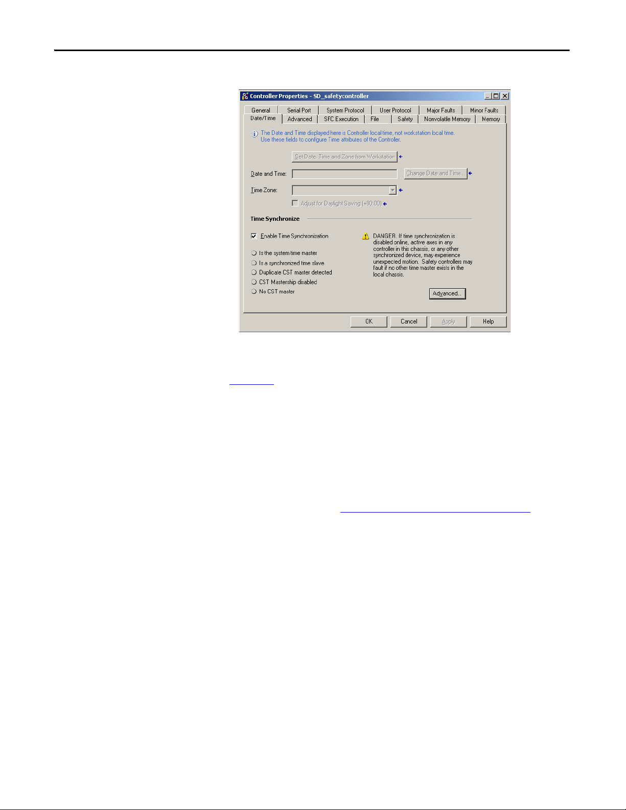
Chapter 3 Configure the Controller
Figure 9 - Date/Time Tab
Configure a Peer Safety Controller
For more information on Time Synchronization, refer to the Integrated
Architecture™ and CIP Sync Configuration Application Solution, publication
IA-AT003
You can add a peer safety controller to the I/O configuration folder of your safety
project to allow standard or safety tags to be consumed. To share safety data
between peer controllers, you produce and consume controller-scoped safety
tags.
For details on configuring the peer safety controllers and producing and
consuming safety tags, see Produced/Consumed Safety Tags on page 86
.
.
42 Rockwell Automation Publication 1756-UM022A-EN-P - November 2012
Page 43

Communicate over Networks
TIP
Top ic Pag e
The Safety Ne twork 43
EtherNet/IP Communication 49
Control Net Communi cation 53
DeviceNet Communication 55
Serial Communication 57
Chapter 4
The Safety Network
The CIP Safety protocol is an end-node to end-node safety protocol that allows
routing of CIP Safety messages to and from CIP Safety devices through bridges,
switches, and routers.
To maintain high integrity when routing through standard bridges, switches, or
routers, each end node within a routable CIP Safety Control System must have a
unique reference. This unique reference is a combination of a safety network
number (SNN) and the node address of the network device.
Managing the Safety Network Number (SNN)
The SNN assigned to safety devices on a network segment must be unique. You
must be sure that a unique SNN is assigned to the following :
• Each CIP Safety network that contains safety devices
• Each chassis that contains one or more GuardLogix controllers
Multiple safety network numbers can be assigned to a CIP Safety subnet or
a ControlBus chassis that contains more than one safety device. However,
for simplicity, we recommend that each CIP Safety subnet have
one, and only one, unique SNN.
The SNN can be software-assigned (time-based) or user-assigned (manual).
These two formats of the SNN are described in the following sections.
Rockwell Automation Publication 1756-UM022A-EN-P - November 2012 43
Page 44

Chapter 4 Communicate over Networks
Time-based Safety Network Number
If the time-based format is selected, the SNN value that is generated represents
the date and time at which the number was generated, according to the personal
computer running the configuration software.
Figure 10 - Time-based Format
Manual Safety Network Number
If the manual format is selected, the SNN represents entered values from 1…9999
decimal.
Figure 11 - Manual Entry
44 Rockwell Automation Publication 1756-UM022A-EN-P - November 2012
Page 45

Communicate over Networks Chapter 4
IMPORTANT
Assigning the Safety Network Number (SNN)
You can allow the Logix Designer application to automatically assign an SNN, or
you can assign the SNN manually.
Automatic Assignment
When a new controller or module is created, a time-based SNN is automatically
assigned. Subsequent new safety-module additions to the same CIP Safety
network are assigned the same SNN defined within the lowest address on that
CIP Safety network.
Manual Assignment
The manual option is intended for routable CIP Safety systems where the
number of network subnets and interconnecting networks is small, and where
users might like to manage and assign the SNN in a logical manner pertaining to
their specific application.
See Changing the Safety Network Number (SNN)
If you assign an SNN manually, make sure that system expansion does not
result in duplication of SNN and node address combinations.
on page 45.
Automatic versus Manual
For typical users, the automatic assignment of an SNN is sufficient. However,
manual manipulation of the SNN is required if the following is true:
• Safety consumed tags are used.
• The project consumes safety input data from a module whose
configuration is owned by some other device.
• A safety project is copied to another hardware installation within the same
routable CIP Safety system.
Changing the Safety Network Number (SNN)
Before changing the SNN you must do the following:
• Unlock the project, if it is safety-locked.
See Safety-lock the Controller
on page 95.
• Delete the safety task signature, if one exists.
See Delete the Safety Task Signature
Rockwell Automation Publication 1756-UM022A-EN-P - November 2012 45
on page 98.
Page 46

Chapter 4 Communicate over Networks
Change the Safety Network Number (SNN) of the Controller
1. In the Controller Organizer, right-click the controller and choose
Properties.
2. On the General tab of the Controller Properties dialog box, click to
the right of the safety network number to open the Safety Network
Number dialog box.
3. Click Time-based and then Generate.
4. Click OK.
Change the Safety Network Number (SNN) of Safety I/O Modules on the CIP Safety Network
This example uses an EtherNet/IP network.
1. Find the first EtherNet/IP communication module in the I/O
Configuration tree.
46 Rockwell Automation Publication 1756-UM022A-EN-P - November 2012
Page 47

Communicate over Networks Chapter 4
2. Expand the safety I/O modules available through the EtherNet/IP
communication module.
3. Double-click the first safety I/O module to view the General tab.
4. Click to the right of the safety network number to open the Safety
Network Number dialog box.
5. Choose Time-based and click Generate to generate a new SNN for that
EtherNet/IP network.
6. Click OK.
7. Click Copy to copy the new SNN to the Windows Clipboard.
8. Open the General Tab of the Module Properties dialog box of the next
safety I/O module under that EtherNet/IP module.
9. Click to the right of the safety network number to open the Safety
Network Number dialog box.
10. Choose Time-based and click Paste to paste that EtherNet/IP network’s
SNN into that device.
11. Click OK.
12. Repeat steps 8
…10 for the remaining safety I/O modules under that
EtherNet/IP communication module.
13. Repeat steps 2
…10 for any remaining network communication modules
under the I/O Configuration tree.
Rockwell Automation Publication 1756-UM022A-EN-P - November 2012 47
Page 48

Chapter 4 Communicate over Networks
Copy and Paste a Safety Network Number (SNN)
If the module’s configuration is owned by another controller, you may need to
copy and paste the SNN from the configuration owner into the module in your
I/O configuration tree.
1. In the software configuration tool of the module’s configuration owner,
open the Safety Network Number dialog box for the module.
2. Click Copy.
3. Click the General tab on the Module Properties dialog box of the I/O
module in the I/O Configuration tree of the consuming controller project.
This consuming controller is not the configuration owner.
4. Click to the right of the safety network number to open the Safety
Network Number dialog box.
5. Click Paste.
6. Click OK.
48 Rockwell Automation Publication 1756-UM022A-EN-P - November 2012
Page 49

Communicate over Networks Chapter 4
EtherNet/IP Communication
For EtherNet/IP network communication in a GuardLogix system, you have
several modules to choose from. For CIP Safety communication, including safety
I/O module control, choose any of the modules shown in Ta b l e 1 2
, except the
1756-EWEB module, which does not support CIP Safety communication.
Ta b l e 1 2
Table 12 - EtherNet/IP Communication Modules and Capabilities
Module Features
1756-ENBT • Connect controllers to I/O modules (requires an adapter for distributed I/O).
1756-EN2T • Perform the same functions as a 1756-ENBT module, with twice the capacity for more
1756-EN2F • Perform the same functions as a 1756-EN2T module.
1756-EN2TXT • Perform the same functions as a 1756-EN2T module.
1756-EN2TR • Perform the same functions as a 1756-EN2T module.
1756-EN3TR • Perform the same functions as the 1756-EN2TR module.
1756-EWEB • Provide customizable web pages for external access to controller information.
lists the modules and their primary features.
• Communicate with other EtherNet/IP devices (messages).
• Serve as a pathway for data sharing between Logix5000 controllers (produce/consume).
• Bridge EtherNet/IP nodes to route messages to devices on other networks.
demanding applications.
• Provide a temporary configuration connection via the USB por t.
• Configure IP addresses quickly by using rotary switches.
• Connect fiber media by an LC fiber connector on the module.
• Operate in extreme environments with -25…70 °C (-13…158 °F) temperatures.
• Support communication on a ring topology for a Device Level Ring (DLR) single-fault
tolerant ring network.
• Three ports for DLR connection.
• Provide remote access via an Internet browser to tags in a local ControlLogix controller.
• Communicate with other EtherNet/IP devices (messages).
• Bridge EtherNet/IP nodes to route messages to devices on other networks.
• Support Ethernet devices that are not EtherNet/IP-based with a socket inter face.
This module does not provide support for I/O or produced/consumed tags, and does not
support CIP Safety communication.
EtherNet/IP communication modules provide the following features:
• Support for messaging, produced/consumed tags, HMI, and distributed
I/O
• Encapsulated messages within standard TCP/UDP/IP protocol
• A common application layer with ControlNet and DeviceNet networks
• Interface via RJ45, category 5, unshielded, twisted-pair cable
• Support for half/full duplex 10 M or 100 M operation
• Work with standard switches
• No network scheduling required
• No routing tables required
Rockwell Automation Publication 1756-UM022A-EN-P - November 2012 49
Page 50

Chapter 4 Communicate over Networks
These products are available for EtherNet/IP networks.
Table 13 - Product for EtherNet/IP Modules
Product Is Used to Required
Studio 5000 environment • Configure the controller project
BOOTP/DHCP utility
RSNetWorx™ for EtherNet/IP
software
RSLinx software • Configure devices
(1) This utility comes with the Studio 5000 environment.
(1)
• Define EtherNet/IP communication
Assign IP addresses to devices on an EtherNet/IP network No
Configure EtherNet/IP devices by IP addresses and/or host names No
• Establish communication between devices
• Provide diagnostics
Yes
Yes
Producing and Consuming Data via an EtherNet/IP Network
The controller supports the ability to produce (send) and consume (receive) tags
over an EtherNet/IP network. Produced and consumed tags each require
connections. The total number of tags that can be produced or consumed is
limited by the number of available connections.
Connections over the EtherNet/IP Network
You indirectly determine the number of connections the safety controller uses by
configuring the controller to communicate with other devices in the system.
Connections are allocations of resources that provide more reliable
communication between devices compared to unconnected messages (message
instructions).
EtherNet/IP connections are unscheduled. An unscheduled connection is
triggered by the requested packet interval (RPI) for I/O control or the program
(such as a MSG instruction). Unscheduled messaging lets you send and receive
data when needed.
The EtherNet/IP communication modules support 128 Common Industrial
Protocol (CIP) connections over an EtherNet/IP network.
50 Rockwell Automation Publication 1756-UM022A-EN-P - November 2012
Page 51

Communicate over Networks Chapter 4
Workstation
Distributed I/O
1756-EN2T Module
(as an Adapter) with
1756 I/O Modules
1756-DNB Module for Remote DeviceNet
Communication
to Standard or Safety
Devices on DeviceNet
Network
Compac tLogix™ Controlle r with
Integrated
EtherNet/IP Port
FlexLogix™ Controller with 1788-ENBT Module
GuardLogix Controller with
1756-EN2T Module
1794-AENT Adapter
with 1794 I/O Modules
1734-AENT Adapter with
1734 I/O Modules
Power Flex® 700S AC
Drive with DriveLogix™
Software
switch
1791ES-IB8XOBV4
Module
1768 Compact GuardLogix Controller with
1768-ENBT Module
EtherNet/IP Communication Example
This example illustrates the following :
• The controllers can produce and consume standard or safety tags between
each other.
• The controllers can initiate MSG instructions that send/receive standard
data or configure devices.
• The EtherNet/IP communication module is used as a bridge, letting the
safety controller produce and consume standard and safety data.
• The personal computer can upload/download projects to the controllers.
• The personal computer can configure devices on the EtherNet/IP
network.
Figure 12 - EtherNet/IP Communication Example
(1)
Rockwell Automation Publication 1756-UM022A-EN-P - November 2012 51
EtherNet/IP Connections for CIP Safety I/O Modules
CIP Safety I/O modules on EtherNet/IP networks are added to the project
under the EtherNet/IP communication module as described in Chapter
Configure, Monitor, and Replace CIP Safety I/O. When you add a CIP Safety
I/O module, the Logix Designer application automatically creates
controller-scoped safety data tags for that module.
(1) Gua rdLogix controll ers do not su pport MSG instructions for safety data.
5, Add,
Page 52

Chapter 4 Communicate over Networks
Figure 13 - Adding EtherNet/IP Modules to the Project
Standard EtherNet/IP Connections
To use a standard EtherNet/IP module with the safety controller, add the module
to the safety controller project and download the project to the GuardLogix
controller.
1. To configure the module, define the IP address, subnet mask, and gateway.
EtherNet/IP
Parameter
IP Address The IP address uniquely identifies the module. The IP address is in the form xxx.xxx.xxx.xxx.
Subnet Mask Subnet addressing is an extension of the IP address scheme that allows a site to use one network
Gateway A gateway connects individual physical networks into a system of networks. When a node needs
Description
where each xxx is a number between 0 and 255. However, there are some values that you cannot
use as the first octet in the address:
• 000.xxx.xxx.xxx
• 127.xxx.xxx.xxx
• 223…255.xxx.xxx.xxx
ID for multiple physical networks. Routing outside of the site continues by dividing the IP
address into a net ID and a host ID via the class. Inside a site, the subnet mask is used to redivide
the IP address into a custom network ID portion and host ID portion. This field is set to 0.0.0.0 by
default.
If you change the subnet mask of an already-configured module, you must cycle power for the
change to take effect.
to communicate with a node on another network, a gateway transfers the data between the t wo
networks. This field is set to 0.0.0.0 by default.
2. After you physically install an EtherNet/IP module and set its IP address,
add the module to the Controller Organizer in your GuardLogix
controller project.
3. Use the Logix Designer application to download the project.
52 Rockwell Automation Publication 1756-UM022A-EN-P - November 2012
Page 53

Communicate over Networks Chapter 4
ControlNet Communication
For ControlNet communication, choose a 1756-CNB or 1756-CNBR module
for standard communication, or a 1756-CN2, 1756-CN2R, or 1756-CN2RXT
module for safety communication.
Table 14 - ControlNet Modules
If your application Select
• Controls standard I/ O modules
• Requires an adapter for distributed I/O on ControlNet links
• Communicates with other ControlNet devices (messages)
• Shares standard data with other Logix5000 controllers (produce/consume)
• Bridges ControlNet links to route messages to devices on other networks
• Performs same functions as a 1756-CNB module
• Also supports redundant ControlNet media
• Performs the same functions supported by the 1756-CNB module with higher
performance
• Supports CIP Safety communication
• Performs same functions as a 1756-CN2 module
• Also supports redundant ControlNet media
• Perform the same functions as a 1756-CN2R module
• Operate in extreme environments with -25…70 °C (-13…158 °F) temperatures
1756-CNB
1756-CNBR
1756-CN2
1756-CN2R
1756-CN2RXT
These products are available for ControlNet networks.
Table 15 - Products for ControlNet Modules
Product Is Used to Required
Studio 5000 environment • Configure the GuardLogix project
• Define ControlNet communication
RSNetWorx for ControlNet software • Configure the ControlNet network
• Define the network update time (NUT)
• Schedule the ControlNet network
RSLinx software • Configure d evices
• Establish communication between devices
• Provide diagnostics
Yes
Yes
Yes
The ControlNet communication modules provide the following:
• Support for messaging, produced/consumed safety and standard tags, and
distributed I/O
• They support the use of coax and fiber repeaters for isolation and increased
distance.
Producing and Consuming Data via a ControlNet Network
The GuardLogix controller supports the ability to produce (send) and consume
(receive) tags over ControlNet networks. The total number of tags that can be
produced or consumed is limited by the number of available connections in the
GuardLogix controller.
Rockwell Automation Publication 1756-UM022A-EN-P - November 2012 53
Page 54

Chapter 4 Communicate over Networks
Connections over the ControlNet Network
The number of connections the controller uses is determined by how you
configure the controller to communicate with other devices in the system.
Connections are allocations of resources that provide more reliable
communication between devices compared to unconnected messages.
ControlNet connections can be scheduled or unscheduled.
Table 16 - ControlNet Connections
Connection Type Description
Scheduled
(unique to the ControlNet network)
Unscheduled An unschedul ed connection is a message transfer between controllers that is triggered by the requested packet interval (RPI) or the program
A scheduled connection is unique to ControlNet communication. A scheduled connection lets you send and receive data repeatedly at a
predetermined interval, which is the requested packet interval (RPI). For example, a connection to an I/O module is a scheduled connection
because you repeatedly receive data from the module at a specified interval. Other scheduled connections include connections to the
following:
• Communication devices
• Produced/consumed tags
On a ControlNet network, you must use RSNetWorx for ControlNet software to enable scheduled connections and establish a net work update
time (NUT). Scheduling a connection reserves network bandwidth to specifically handle the connection.
(such as a MSG instruction). Unscheduled messaging lets you send and receive data when needed.
Unscheduled connections use the remainder of network bandwidth after scheduled connections are allocated.
Safety produced/consumed connections are unscheduled.
The 1756-CNB and 1756-CNBR communication modules support 64 CIP
connections over a ControlNet network. However, we recommend that you
configure no more than 48 connections to maintain optimal performance.
The 1756-CN2 module supports 128 CIP connections over the ControlNet
network.
ControlNet Communication Example
This example illustrates the following :
• GuardLogix controllers can produce and consume standard or safety tags
between each other.
• GuardLogix controllers can initiate MSG instructions that send/receive
standard data or configure devices.
• The 1756-CN2 module can be used as a bridge, letting the GuardLogix
controller produce and consume standard and safety data to and from I/O
devices.
• The personal computer can upload/download projects to the controllers.
• The personal computer can configure devices on the ControlNet network,
and it can configure the network itself.
(1)
(1) Gua rdLogix controll ers do not su pport MSG instructions for safety data.
54 Rockwell Automation Publication 1756-UM022A-EN-P - November 2012
Page 55

Figure 14 - ControlNet Communication Example
ControlNet
Distributed I/O
1756-CN2 Module (as
an Adapter) with
1756 I/O Modules
1794-ACN15 Adapter with
1794 I/O Modules
Pers onal
Computer/
Wor kst ati on
GuardLogix Controller with
1756-CN2 Module
GuardLogix Controller
with 1756-DNB
Module
1734-ACNR Adapter with
1734 I/O Modules
(1)
PanelView™ Terminal
PLC-5®/40C Controller
PowerFlex 700S AC
Drive with
DriveLogix Software
1756-DNB Module
to DeviceNet Network
with CIP Safety I/O
to DeviceNet Network
with CIP Safety I/O
Compact GuardLogix Controller with
1768-CNB Module
Communicate over Networks Chapter 4
DeviceNet Communication
(1) The 1734-ACN adapter does not support POINT Guard Safety I/O modules.
ControlNet Connections for Distributed I/O
To communicate with distributed I/O modules over a ControlNet network, add
a ControlNet bridge, a ControlNet adapter, and I/O modules to the controller’s
I/O Configuration folder.
To communicate and exchange data with CIP Safety I/O modules on DeviceNet
networks, you need a 1756-DNB module in the local chassis.
For information on how to install your 1756-DNB module, refer to the
ControlLogix DeviceNet Scanner Module Installation Instructions, publication
1756-IN566.
The 1756-DNB module supports communication with DeviceNet Safety devices
and standard DeviceNet devices. You can use both types.
Rockwell Automation Publication 1756-UM022A-EN-P - November 2012 55
Page 56

Chapter 4 Communicate over Networks
These products are used with the DeviceNet networks and 1756-DNB module.
Table 17 - Product for Use with DeviceNet Networks
Product Is used to Required
Studio 5000 environment • Config ure ControlLogix p rojects.
RSNetWorx for DeviceNet software • Configure DeviceNet devices.
RSLinx Classic or
RSLinx Enterprise software
• Define DeviceNet communication.
• Define the scan list for those devices.
• Configure communication devices.
• Provide diagnostics.
• Establish communication between devices.
Yes
Yes
Yes
DeviceNet Connections for CIP Safety I/O Modules
To access CIP Safety devices on DeviceNet networks, add a 1756-DNB to the
I/O Configuration tree of the GuardLogix controller project.
CIP Safety I/O modules on DeviceNet networks are added to the project under
the 1756-DNB module, as described in Chapter
and Replace CIP Safety I/O. When you add a CIP Safety I/O module, the Logix
Designer application automatically creates controller-scoped safety data tags for
that module.
5, Add, Configure, Monitor,
Figure 15 - DeviceNet Module in Controller in the I/O Configuration Tree
Standard DeviceNet Connections
If you use standard DeviceNet I/O with your GuardLogix controller, you need to
allocate two connections for each 1756-DNB module. One connection is for
module status and configuration. The other connection is a rack-optimized
connection for the DeviceNet I/O data.
56 Rockwell Automation Publication 1756-UM022A-EN-P - November 2012
Page 57

Communicate over Networks Chapter 4
To use the 1756-DNB module to access standard data via the DeviceNet
network, you must use RSNetWorx for DeviceNet software to do the following:
• Create a configuration file for the network.
• Configure each standard device on the network.
• Configure the 1756-DNB.
• Add the standard I/O devices to the 1756-DNB scan list.
When you add the 1756-DNB module to the I/O Configuration of the
controller, the Logix Designer application automatically creates a set of standard
tags for the input, output, and status data of the network.
Serial Communication
To operate the GuardLogix controller on a serial network, you need the
following:
• A workstation with a serial port
• RSLinx software to configure the serial communication driver
• The Logix Designer application to configure the serial port of the
controller
For the controller to communicate to a workstation or other device over the serial
network, you must follow these steps.
1. Configure the serial communication driver for the workstation.
2. Configure the serial port of the controller.
Use this mode For
DF1 Point-to-point Communication between the controller and one other DF1-protocol-compatible device.
This is the default System mode. This mode is typically used to program the controller
through its serial port.
DF1 Master Control of polling and message transmission between the master and slave nodes.
The master/slave network includes one controller configured as the master node and as
many as 254 slave nodes. Link slave nodes by using modems or line drivers.
A master/slave network can have node numbers from 0…254. Each node must have a
unique node address. Also, at least 2 nodes must exist to define your link as a network
(1 master and 1 slave station are the two nodes).
DF1 Slave A controller operating as a slave station in a master/slave serial communication network.
When there are multiple slave stations on the network, link slave stations by using
modems or line drivers to the master. When you have a single slave station on the
network, you do not need a modem to connect the slave station to the master. You can
configure the control parameters for no handshaking. You can connect 2…255 nodes to
one link. In DF1 Slave mode, a controller uses DF1 half-duplex protocol.
One node is designated as the master and it controls who has access to the link. All the
other nodes are slave stations and must wait for permission from the master before
transmitting.
DH-485 Communicating with other DH-485 devices multi-master, token passing network
allowing programming and peer-to-peer messaging.
Rockwell Automation Publication 1756-UM022A-EN-P - November 2012 57
Page 58

Chapter 4 Communicate over Networks
Notes:
58 Rockwell Automation Publication 1756-UM022A-EN-P - November 2012
Page 59

Chapter 5
Add, Configure, Monitor, and Replace
CIP Safety I/O
Top ic P age
Adding CIP Safety I/O Modules 59
Configure CIP Safety I/O Modules 60
Setting the Safety Network Number (SNN) 61
Using Unicast Connections on EtherNet/IP Networks 61
Setting the Connection Reaction Time Limit 61
Understanding the Configuration Signature 65
Reset Safety I/O Module Ownership 66
Addressing Safety I/O Data 66
Monitor Safety I/O Module Status 67
Resetting a Module to Out-of-box Condition 69
Replacing a Module by Using the Logix Designer Application 69
Replacing a POINT Guard I/O Module by Using RSNetWorx for DeviceNet Software 76
Adding CIP Safety I/O Modules
For more information on installation, configuration, and operation of CIP
Safety I/O modules, refer to these resources:
• Guard I/O DeviceNet Safety Modules User Manual, publication
1791DS-UM001
• Guard I/O EtherNet/IP Safety Modules User Manual, publication
1791ES-UM001
• POINT Guard I/O Safety Modules Installation and User Manual,
publication 1734-UM013
• Logix Designer application online help
When you add a module to the system, you must define a configuration for the
module, including the following:
• Node address for DeviceNet networks
You cannot set the node address of an CIP Safety I/O module on
DeviceNet networks via the Logix Designer application. Module node
addresses are set via rotary switches on the modules.
Rockwell Automation Publication 1756-UM022A-EN-P - November 2012 59
Page 60

Chapter 5 Add, Configure, Monitor, and Replace CIP Safety I/O
TIP
TIP
• IP address for EtherNet/IP networks
To set the IP address, you can adjust the rotary switches on the module, use
DHCP software, available from Rockwell Automation, or retrieve the
default address from nonvolatile memory.
• Safety network number (SNN)
See page 61
• Configuration signature
for information on setting the SNN.
Configure CIP Safety I/O Modules
See page 65
automatically and when you need to set it.
• Reaction time limit
See page 61
• Safety input, output, and test parameters
You can configure CIP Safety I/O modules via the GuardLogix controller by
using the Logix Designer application.
Add the CIP Safety I/O module to the communication module under the I/O
Configuration folder of the controller project.
1. Right-click the appropriate network and choose New Module.
2. Expand the Safety category and choose a CIP Safety I/O module.
3. Specify the module properties.
for information on when the configuration signature is set
for information on setting the reaction time limit.
Safety I/O modules support standard and safety data. Module
configuration defines what data is available.
You cannot add or delete a CIP Safety I/O module while online.
a. Modify the Module Definition settings, if required, by clicking
Change.
60 Rockwell Automation Publication 1756-UM022A-EN-P - November 2012
Page 61

Add, Configure, Monitor, and Replace CIP Safety I/O Chapter 5
b. Type a name for the new module.
c. Enter the node address or IP address of the module on its connecting
network.
Only unused node numbers are included in the pull-down menu.
d. Modify the safety network number (SNN), if required, by clicking the
button.
Setting the Safety Network Number (SNN)
See page 61
e. Set module configuration parameters by using the Input Configuration,
Test Output, and Output Configuration tabs.
Refer to online help for more information on CIP Safety I/O module
configuration.
f. Set the Connection Reaction Time Limit by using the Safety tab.
See page 61
The assignment of a time-based SNN is automatic when adding new Safety I/O
modules. Subsequent safety-module additions to the same network are assigned
the same SNN defined within the lowest address on that CIP Safety network.
For most applications, the automatic, time-based SNN is sufficient. However,
there are cases in which manipulation of an SNN is required.
See Assigning the Safety Network Number (SNN)
for details.
for details.
on page 45.
Using Unicast Connections on EtherNet/IP Networks
Setting the Connection Reaction Time Limit
Rockwell Automation Publication 1756-UM022A-EN-P - November 2012 61
Unicast connections are point-to-point connections between a source and a
destination node. You do not have to enter a minimum or maximum RPI range or
default value for this type of connection.
To configure unicast connections, choose the Connection tab and check Use
Unicast Connection over Ethernet/IP.
The Connection Reaction Time Limit is the maximum age of safety packets on
the associated connection. If the age of the data used by the consuming device
exceeds the Connection Reaction Time Limit, a connection fault occurs. The
Connection Reaction Time Limit is determined by the following equations:
Input Connection Reaction Time Limit =
Input RPI x [Timeout Multiplier + Network Delay Multiplier]
Output Connection Reaction Time Limit =
Safety Task Period x [Timeout Multiplier + Network Delay Multiplier - 1]
Page 62

Chapter 5 Add, Configure, Monitor, and Replace CIP Safety I/O
The Connection Reaction Time Limit is shown on the Safety tab of the Module
Properties dialog box.
Figure 16 - Connection Reaction Time Limit
Specify the Requested Packet Interval (RPI)
The RPI specifies the period at which data updates over a connection. For
example, an input module produces data at the RPI that you assign.
For safety input connections, you can set the RPI on the Safety tab of the Module
Properties dialog box. The RPI is entered in 1 ms increments, with a range of
1…100 ms. The default is 10 ms.
The Connection Reaction Time Limit is adjusted immediately when the RPI is
changed via the Logix Designer application.
Figure 17 - Requested Packet Interval
For safety output connections, the RPI is fixed at the safety task period. If the
corresponding Connection Time Reaction Limit is not satisfactory, you can
adjust the safety task period via the Safety Task Properties dialog box.
See Safety Task Period Specification on page 80
for more information on the
safety task period.
For typical applications, the default RPI is usually sufficient. For more complex
requirements, use the Advanced button to modify the Connection Reaction
Time Limit parameters, as described on page 63
.
62 Rockwell Automation Publication 1756-UM022A-EN-P - November 2012
Page 63

Add, Configure, Monitor, and Replace CIP Safety I/O Chapter 5
IMPORTANT
View the Maximum Observed Network Delay
When the GuardLogix controller receives a safety packet, the software records
the maximum observed network delay. For safety inputs, the Maximum
Observed Network Delay displays the round-trip delay from the input module to
the controller and the acknowledge back to the input module. For safety outputs,
it displays the round-trip delay from the controller to the output module and the
acknowledge back to the controller. The Maximum Observed Network Delay is
shown on the Safety tab of the Module Properties dialog box. When online, you
can reset the Maximum Observed Network Delay by clicking Reset.
Figure 18 - Resetting the Max Observed Network Delay
The actual Maximum Network Delay time from the producer to the
consumer is less than the value displayed in the Maximum Network Delay
field on the Safety tab. In general, the actual maximum message delay is
approximately one-half the Maximum Network Delay value that is
displayed.
Setting the Advanced Connection Reaction Time Limit Parameters
Configure connection parameters like the timeout multiplier and network delay
multiplier on the Advanced Connection Reaction Time Limit dialog box.
Figure 19 - Advanced Configuration
Rockwell Automation Publication 1756-UM022A-EN-P - November 2012 63
Page 64

Chapter 5 Add, Configure, Monitor, and Replace CIP Safety I/O
EXAMPLE
Timeout Multiplier
The Timeout Multiplier determines the number of RPIs to wait for a packet
before declaring a connection timeout. This translates into the number of
messages that may be lost before a connection error is declared.
For example, a Timeout Multiplier of 1 indicates that messages must be received
during every RPI interval. A Timeout Multiplier of 2 indicates that 1 message
may be lost as long as at least 1 message is received in 2 times the RPI (2 x RPI).
Network Delay Multiplier
The Network Delay Multiplier defines the message transport time that is
enforced by the CIP Safety protocol. The Network Delay Multiplier specifies the
round-trip delay from the producer to the consumer and the acknowledge back to
the producer. You can use the Network Delay Multiplier to reduce or increase the
Connection Reaction Time Limit in cases where the enforced message transport
time is significantly less or more than the RPI. For example, adjusting the
Network Delay Multiplier may be helpful when the RPI of an output connection
is the same as a lengthy safety task period.
For cases where the input RPI or output RPI are relatively slow or fast as
compared to the enforced message delay time, the Network Delay Multiplier can
be approximated by using one of the two methods.
Method 1: Use the ratio between the input RPI and the safety task period. Use
this method only under all of the following conditions:
• If the path or delay is approximately equal to the output path or delay.
• The input RPI has been configured so that the actual input message
transport time is less than the input RPI.
• The safety task period is slow relative to the Input RPI.
Under these conditions, the Output Network Delay Multiplier can be
approximated as follows:
Input Network Delay Multiplier x [Input RPI ÷ Safety Task Period]
Calculate the Approximate Output Network Delay Multiplier
If:
Input RPI = 10 ms
Input Network Delay Multiplier = 200%
Safety Task Period = 20 ms
Then, the Output Network Delay Multiplier equals:
200% x [10 ÷ 20] = 100%
Method 2: Use the Maximum Observed Network Delay. If the system is run for
an extended period of time through its worst-case loading conditions, the
Network Delay Multiplier can be set from the Maximum Observed Network
64 Rockwell Automation Publication 1756-UM022A-EN-P - November 2012
Page 65

Add, Configure, Monitor, and Replace CIP Safety I/O Chapter 5
EXAMPLE
Delay. This method can be used on an input or output connection. After the
system has been run for an extended period of time through its worst-case loading
conditions, record the Maximum Observed Network Delay.
The Network Delay Multiplier can be approximated by the following equation:
[Maximum Observed Network Delay + Margin_Factor] ÷ RPI
Calculate the Network Delay Multiplier from Maximum
Observed Network Delay
If:
RPI = 50 ms
Maximum Observed Network Delay = 20 ms
Margin_Factor = 10
Then, the Network Delay Multiplier equals:
[20 + 10] ÷ 50 = 60%
Table 18 - Additional Resources
Understanding the Configuration Signature
Resource Description
GuardLogix 5570 Controllers Systems Safety Reference
Manual, publication 1756-RM099
Guard I/O DeviceNet Safety Modules User Manual, publication
1791DS-UM001
Guard I/O EtherNet/IP Safety Modules User Manual,
publication 1791ES-UM001
Provides information on calculating reaction times.
Each safety device has a unique configuration signature, which defines the
module configuration. The configuration signature is composed of an ID
number, date, and time, and is used to verify a module’s configuration.
Configuration via the Logix Designer Application
When the I/O module is configured by using the Logix Designer application, the
configuration signature is generated automatically. You can view and copy the
configuration signature via the Safety tab on the Module Properties dialog box.
Figure 20 - View and Copy the Configuration Signature
Rockwell Automation Publication 1756-UM022A-EN-P - November 2012 65
Page 66
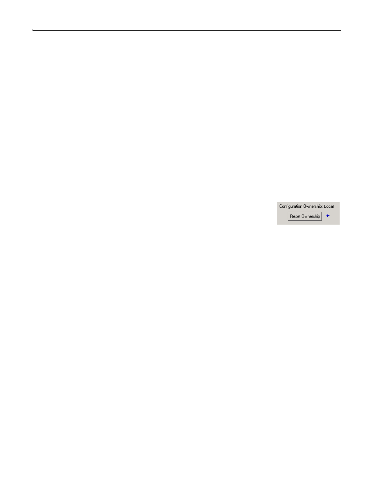
Chapter 5 Add, Configure, Monitor, and Replace CIP Safety I/O
TIP
TIP
Different Configuration Owner (listen only connection)
When the I/O module configuration is owned by another controller, you need to
copy the module configuration signature from its owner’s project and paste it
into the Safety tab of the Module Properties dialog box.
If the module is configured for inputs only, you can copy and paste the
configuration signature. If the module has safety outputs, they are owned by the
controller that owns the configuration, and the configuration signature text box is
unavailable.
Reset Safety I/O Module Ownership
Addressing Safety I/O Data
When the controller project is online, the Safety tab of the Module Properties
dialog box displays the current configuration ownership. When the opened
project owns the configuration, Local is displayed. When a second device owns
the configuration, Remote is displayed, along with the safety network number
(SNN), and node address or slot number of the configuration owner.
Communication error is displayed if the module read fails.
When online, you can reset the module to its out-ofbox configuration by clicking Reset Ownership.
You cannot reset ownership when there are pending edits to the module
properties, when a safety task signature exists, or when safety-locked.
When you add a module to the I/O configuration folder, the Logix Designer
application automatically creates controller-scoped tags for the module.
I/O information is presented as a set of tags. Each tag uses a structure of data,
depending on the type and features of the I/O module. The name of a tag is based
on the module’s name in the system.
66 Rockwell Automation Publication 1756-UM022A-EN-P - November 2012
Page 67
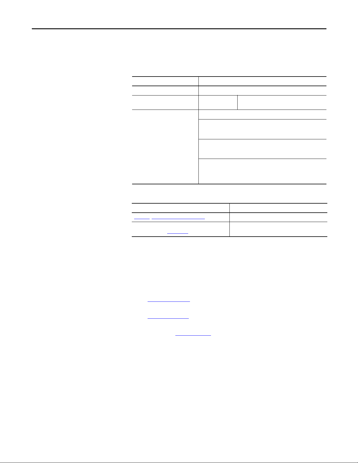
Add, Configure, Monitor, and Replace CIP Safety I/O Chapter 5
A CIP Safety I/O device address follows this format:
Modulename:Type.Member
Table 19 - CIP Safety I/O Module Address Format
Where Is
Modulename The name of the CIP Safety I/O module
Typ e Type of d ata : In put : I
Member Specific data from the I/O module
Input-only Module: Modulename:I.RunMode
Output-only Module: Modulename:I.RunMode
Combination I/O: Modulename:I.RunMode
Output: O
Modulename:I.ConnectionFaulted
Modulename:I.Input Members
Modulename:I.ConnectionFaulted
Modulename:O.Output Members
Modulename:I.ConnectionFaulted
Modulename:I.Input Members
Modulename:O.Output Members
Monitor Safety I/O Module Status
Table 20 - Additional Resources
Resource Description
Chapter
9, Monitor Status and Handle Faults Contains information on monitoring safety tag data
Logix5000 Controllers I/O and Tag Data Programming
Manual, publication 1756-PM004
Provides information on addressing standard I/O modules
You can monitor safety I/O module status via explicit messaging or via the status
indicators on the I/O modules.
These publications provide information on I/O module troubleshooting:
• Guard I/O DeviceNet Safety Modules User Manual, publication
1791DS-UM001
• Guard I/O EtherNet/IP Modules User Manual, publication
1791ES-UM001
• POINT Guard I/O Safety Modules Installation and User Manual,
publication 1734-UM013
Rockwell Automation Publication 1756-UM022A-EN-P - November 2012 67
Page 68

Chapter 5 Add, Configure, Monitor, and Replace CIP Safety I/O
Table 21 - Status Indicator Operation
Indicator Status Description
Guard I/O DeviceNet Modules Guard I/O EtherNet/IP Modules POINT Guard I/O Modules
Off No power.
Green, On Operating under normal conditions.
Module
Status (MS)
Network
Status (NS)
Input Points
(INx)
Output Points
(Ox)
Tes t O utp ut
Point s (Tx)
LOCK Yellow, On Device configuration is locked.
IN PWR Green, Off No input power.
OUT PWR Green, Off No output power.
PWR Green, Off
Green, Flashing Device is idle.
Red, Flashing A recoverable fault exists. A recoverable fault exists or a firmware update is in progress.
Red, On An unrecoverable fault exists.
Red/Green,
Flashing
Off Device is not online or may not have power.
Green, On Device is online; connections are established.
Green, Flashing Device is online; no connections established.
Red, Flashing Communication timeout. Communication timeout or a firmware update is in progress.
Red, On Communication failure. The device has detected an error that has prevented network communication.
Red/Green,
Flashing
Off Safety input is OFF.
Yellow, On Safety input is ON.
Red, On An error has occurred in the input circuit.
Red, Flashing When dual-channel operation is selected, an error has occurred in the partner input circuit.
Off Safety output is OFF.
Yel low, On Sa fety outp ut i s ON .
Red, On An error has occurred in the output circuit.
Red, Flashing When dual-channel operation is selected, an error has occurred in the partner output circuit.
Off
Red. On An error has occurred in the output circuit.
Yellow, Flashing Device configuration is valid, but device is not
Yellow, Off Invalid, no configuration data, or device has
Green, On Input power voltage is within specification.
Yellow, On Input power voltage is out of specification.
Green, On Output power voltage is within specification.
Yellow, On Output power voltage is out of specification.
Green, On Power voltage is within specification.
Yel low, On Power voltage is out of specification.
Self-tests in progress. Self-tests are in progress or the module is not configured properly. See the network status
Device is in Communication Faulted state or
safety network number (SNN) is being set.
Not applicable.
locked.
been configured.
Not applicable.
indicator for more information.
Self-test in progress.
The outp ut is OFF.
The Logix Designer application does not suppor t this function.
Not applicable.
Not applicable.Yel low, On The out put i s ON .
Not applicable.
No power.
68 Rockwell Automation Publication 1756-UM022A-EN-P - November 2012
Page 69
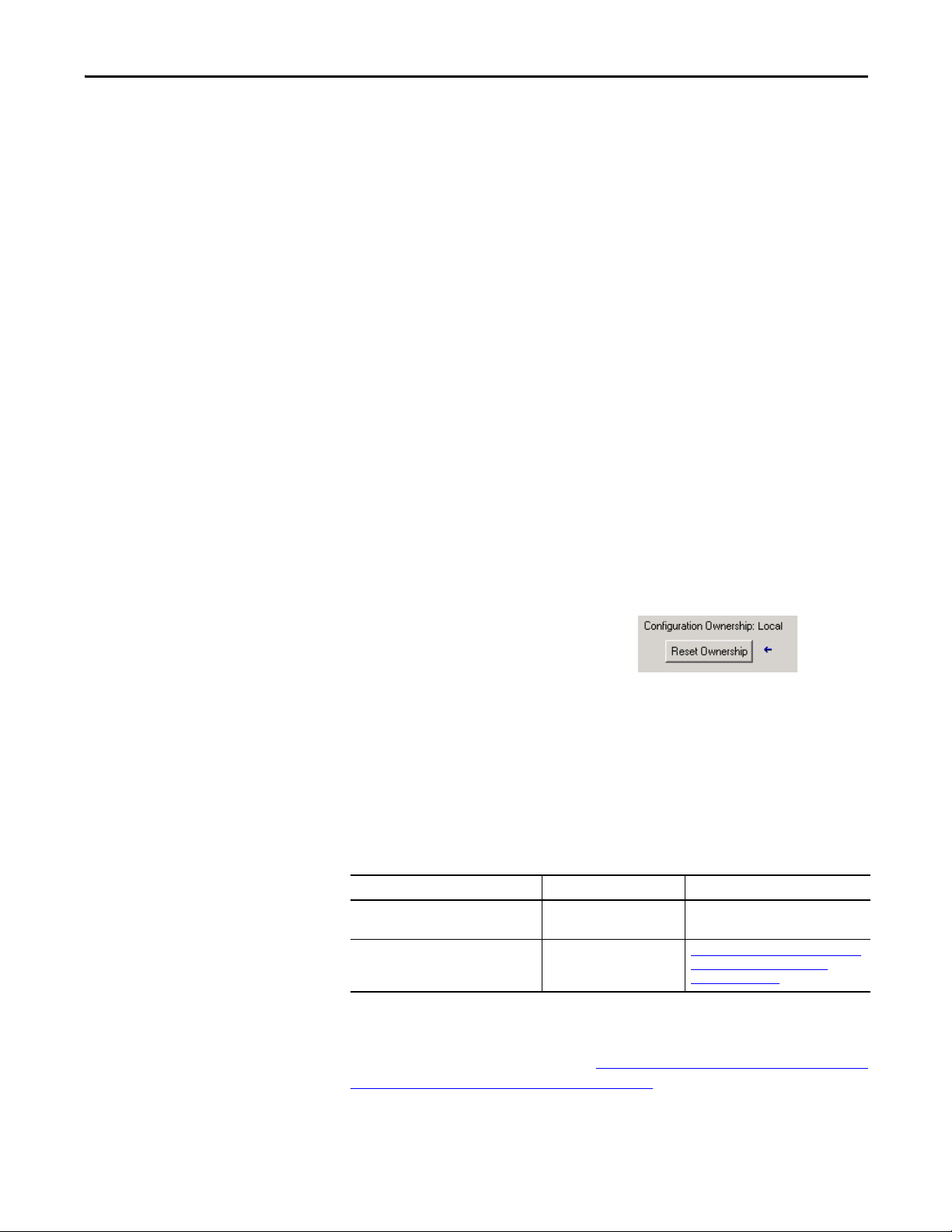
Add, Configure, Monitor, and Replace CIP Safety I/O Chapter 5
TIP
Resetting a Module to Outof-box Condition
If a Guard I/O module was used previously, clear the existing configuration
before installing it on a safety network by resetting the module to its out-of-box
condition.
When the controller project is online, the Safety tab of the Module Properties
dialog box displays the current configuration ownership. When the opened
project owns the configuration, Local is displayed. When a second device owns
the configuration, Remote is displayed, along with the safety network number
(SNN), and node address or slot number of the configuration owner.
Communication error is displayed if the module read fails.
If the connection is Local, you must inhibit the module connection before
resetting ownership. Follow these steps to inhibit the module.
1. Right-click the module and choose Properties.
2. Click the Connection tab.
3. Check Inhibit Connection.
4. Click Apply and then OK.
Follow these steps to reset the module to its out-of-box configuration when
online.
Replacing a Module by Using the Logix Designer Application
1. Right-click the module and choose Properties.
2. Click the Safety tab.
3. Click Reset Ownership.
You cannot reset ownership when there are pending edits to the module
properties, when a safety task signature exists, or when safety-locked.
You can use the Logix Designer application to replace a Guard I/O module on an
Ethernet network. To replace a Guard I/O module on a DeviceNet network,
your choice depends on the type of module.
Table 22 - Software
If you are using a Use See
1791DS Guard I/O module with 1756-DNB
adapter
1734 POINT Guard I/O module with a
1734-PDN adapter
the Logix Designer application Below
RSNetWorx for DeviceNet
software
Replacing a POINT Guard I/O Module
Using RSNetWorx for DeviceNet
Software on page 76
by
If you are relying on a portion of the CIP Safety system to maintain SIL 3
behavior during module replacement and functional testing, the Configure
Always feature may not be used. Go to Replacement with ‘Configure Only When
No Safety Signature Exists’ Enabled on page 70.
Rockwell Automation Publication 1756-UM022A-EN-P - November 2012 69
Page 70

Chapter 5 Add, Configure, Monitor, and Replace CIP Safety I/O
If the entire routable CIP Safety control system is not being relied on to maintain
SIL 3/PLe during the replacement and functional testing of a module, the
Configure Always feature may be used. Go to Replacement with ‘Configure
Always’ Enabled on page 74.
Module replacement is configured on the Safety tab of the GuardLogix
controller.
Figure 21 - Safety I/O Module Replacement
Replacement with ‘Configure Only When No Safety Signature Exists’ Enabled
When a module is replaced, the configuration will be downloaded from the
safety controller if the DeviceID of the new module matches the original. The
DeviceID is a combination of the node/IP address and the Safety Network
Number (SNN) and is updated whenever the SNN is set.
If the project is configured as ‘Configure Only When No Safety Signature Exists’,
follow the appropriate steps in Ta b l e 2 3
based on your scenario. Once you have completed the steps correctly, the
DeviceID will match the original, enabling the safety controller to download the
proper module configuration, and re-establish the safety connection.
Table 23 - Replacing a Module
GuardLogix Safety
Signature Exists
No No SNN
Yes or No Same SNN as original
Replacement
Module Condition
(Out-of-box)
safety task
configuration
to replace a POINT Guard I/O module
Action Required
None. The module is ready for use.
None. The module is ready for use.
70 Rockwell Automation Publication 1756-UM022A-EN-P - November 2012
Page 71

Table 23 - Replacing a Module
Add, Configure, Monitor, and Replace CIP Safety I/O Chapter 5
GuardLogix Safety
Signature Exists
Yes No SNN
Yes
No See Scenario 3 - Replacement Module SNN is Different from Original
Replacement
Module Condition
(Out-of-box)
Different SNN from
original safety task
configuration
Action Required
See Scenario 1 - Replacement Module is Out-of-box and Safety
Signature Exists on page 71.
See
Scenario 2 - Replacement Module SNN is Different from Original
and Safety Signature Exists on page 72.
and No Safety Signature Exists on page 74.
Scenario 1 - Replacement Module is Out-of-box and Safety Signature Exists
1. Remove the old I/O module and install the new module.
2. Right-click the replacement POINT Guard I/O module and choose
Properties.
3. Click to the right of the safety network number to open the Safety
Network Number dialog box.
4. Click Set.
Rockwell Automation Publication 1756-UM022A-EN-P - November 2012 71
Page 72

Chapter 5 Add, Configure, Monitor, and Replace CIP Safety I/O
Scenario 2 - Replacement Module SNN is Different from Original and Safety Signature Exists
5. Verify that the Network Status (NS) status indicator is alternating
red/green on the correct module before clicking Yes on the confirmation
dialog box to set the SNN and accept the replacement module.
6. Follow your company-prescribed procedures to functionally test the
replaced I/O module and system and to authorize the system for use.
1. Remove the old I/O module and install the new module.
2. Right-click your POINT Guard I/O module and choose Properties.
3. Click the Safety tab.
4. Click Reset Ownership.
5. Click OK.
6. Right-click your controller and choose Properties.
72 Rockwell Automation Publication 1756-UM022A-EN-P - November 2012
Page 73

Add, Configure, Monitor, and Replace CIP Safety I/O Chapter 5
7. Click to the right of the safety network number to open the Safety
Network Number dialog box.
8. Click Set.
9. Verify that the Network Status (NS) status indicator is alternating
red/green on the correct module before clicking Yes on the confirmation
dialog box to set the SNN and accept the replacement module.
10. Follow your company-prescribed procedures to functionally test the
replaced I/O module and system and to authorize the system for use.
Rockwell Automation Publication 1756-UM022A-EN-P - November 2012 73
Page 74

Chapter 5 Add, Configure, Monitor, and Replace CIP Safety I/O
Scenario 3 - Replacement Module SNN is Different from Original and No Safety Signature Exists
1. Remove the old I/O module and install the new module.
2. Right-click your POINT Guard I/O module and choose Properties.
3. Click the Safety tab.
4. Click Reset Ownership.
5. Click OK.
6. Follow your company-prescribed procedures to functionally test the
replaced I/O module and system and to authorize the system for use.
Replacement with ‘Configure Always’ Enabled
ATT EN TI ON : Enable the ‘Configure Always’ feature only if the entire CIP Safety
Control System is not being relied on to maintain SIL 3 behavior during the
replacement and functional testing of a module.
Do not place modules that are in the out-of-box condition on a CIP Safety network
when the Configure Always feature is enabled, except while following this
replacement procedure.
When the ‘Configure Always’ feature is enabled in the controller project, the
controller automatically checks for and connects to a replacement module that
meets all of the following requirements:
• The controller has configuration data for a compatible module at that
network address.
• The module is in out-of-box condition or has an SNN that matches the
configuration.
74 Rockwell Automation Publication 1756-UM022A-EN-P - November 2012
Page 75

Add, Configure, Monitor, and Replace CIP Safety I/O Chapter 5
If the project is configured for ‘Configure Always’, follow the appropriate steps to
replace a POINT Guard I/O module.
1. Remove the old I/O module and install the new module.
a. If the module is in out-of-box condition, go to step 6
.
No action is needed for the GuardLogix controller to take ownership of
the module.
b. If an SNN mismatch error occurs, go to the next step to reset the
module to out-of-box condition.
2. Right-click your POINT Guard I/O module and choose Properties.
3. Click the Safety tab.
4. Click Reset Ownership.
5. Click OK.
6. Follow your company-prescribed procedures to functionally test the
replaced I/O module and system and to authorize the system for use.
Rockwell Automation Publication 1756-UM022A-EN-P - November 2012 75
Page 76

Chapter 5 Add, Configure, Monitor, and Replace CIP Safety I/O
Replacing a POINT Guard I/O Module by Using RSNetWorx for DeviceNet Software
Follow these steps to replace a POINT Guard I/O module when the module and
the controller are on a DeviceNet network.
1. Replace the module and match the node number of the original module.
2. In RSNetWorx for DeviceNet software, open your project.
If the replacement module is out-of-box or has an SNN that does not
match the original module, the module appears with an exclamation mark.
3. Right-click the module and choose Download to Device.
4. Click Yes to confirm.
5. Click Download on the Safety Network Number Mismatch dialog box to
set the SNN on the replacement module.
76 Rockwell Automation Publication 1756-UM022A-EN-P - November 2012
Page 77

Add, Configure, Monitor, and Replace CIP Safety I/O Chapter 5
6. Verify that the (NS) Network Status indicator is flashing on the correct
module and click OK to set the SNN on that device.
RSNetWorx for DeviceNet software confirms that the SNN has ben set.
Once the download is completes successfully, the main project view
displays this message: ‘The device at address xx has been downloaded. Any
device-specific messages related to the download operation are displayed
separately.’
Assuming this is the proper configuration from the original DNT file, the
SNN and configuration signature now match that of the original. If you
are already connected to the controller, a connection is made. The
controller does not need to be taken out of Run mode to download to the
replacement module.
Rockwell Automation Publication 1756-UM022A-EN-P - November 2012 77
Page 78

Chapter 5 Add, Configure, Monitor, and Replace CIP Safety I/O
If you download this configuration to a temporary setup, place the module
on the network and it automatically connects to the controller.
If the configuration downloaded to the module was not from the original
DNT file, the configuration signature will not match the original. Even if
you recreate the same parameters in a new DNT file, the time and date
portions of the signature will be different so the connection to the
controller is not made. If this occurs, click the Safety Connection tab for
the controller that prompted you that the configuration signature is
different and provides you with the option to match the new configuration
signature. However, you should first re-validate the safety system, because
it is not using the original DNT file.
7. Click Yes.
This takes the controller out of Run mode and prompts you to download
the changes.
8. Click Yes to download the new connection configuration to the controller.
After the download is complete, place the controller back in Run mode
and the connection to the replacement module is established.
9. Follow your company-prescribed procedures to functionally test the
replaced I/O module and system and to authorize the system for use.
78 Rockwell Automation Publication 1756-UM022A-EN-P - November 2012
Page 79

Develop Safety Applications
Top ic Pag e
The Safety Task 80
Safety Programs 81
Safety Routines 82
Safety Tags 82
Produced/Consumed Safety Tags 86
Safety Tag Mapping 92
Safety Application Protection 95
Programming Restrictions 98
Chapter 6
This chapter explains the components that make up a safety project and provides
information on using features that help protect safety application integrity, such
as the safety task signature and safety-locking.
For guidelines and requirements for developing and commissioning SIL 3 and
PLe safety applications, refer to the GuardLogix 5570 Controller Systems Safety
Reference Manual, publication 1756-RM099
.
The Safety Reference Manual addresses the following:
• Creating a detailed project specification
• Writing, documenting, and testing the application
• Generating the safety task signature to identify and protect the project
• Confirming the project by printing or displaying the uploaded project and
manually comparing the configurations, safety data, and safety program
logic
• Verifying the project through test cases, simulations, functional
verification tests, and an independent safety review, if required
• Locking the safety application
• Calculating system reaction time
Rockwell Automation Publication 1756-UM022A-EN-P - November 2012 79
Page 80

Chapter 6 Develop Safety Applications
The Safety Task
When you create a safety controller project, the Logix Designer application
automatically creates a safety task with a safety program and a main (safety)
routine.
Figure 22 - Safety Task in the Controller Organizer
Within the safety task, you can use multiple safety programs, composed of
multiple safety routines. The GuardLogix controller supports one safety task.
The safety task cannot be deleted.
You cannot schedule standard programs or execute standard routines within the
safety task.
Safety Task Period Specification
The safety task is a periodic timed task. You select the task priority and watchdog
time via the Task Properties - Safety Task dialog box. Open the dialog box by
right-clicking the Safety Task and choosing Properties.
Figure 23 - Configuring the Safety Task Period
80 Rockwell Automation Publication 1756-UM022A-EN-P - November 2012
Page 81

Develop Safety Applications Chapter 6
The safety task should be a high priority. You specify the safety task period (in
ms) and the safety task watchdog (in ms). The safety task period is the period at
which the safety task executes. The safety task watchdog is the maximum time
allowed from the start of safety task execution to its completion.
The safety task period is limited to a maximum of 500 ms and cannot be
modified online. Be sure that the safety task has enough time to finish logic
execution before it is triggered again. If a safety task watchdog timeout occurs, a
nonrecoverable safety fault is generated in the safety controller.
The safety task period directly affects system reaction time.
The GuardLogix 5570 Controller Systems Safety Reference Manual, publication
1756-RM099
, provides detailed information on calculating system reaction time.
Safety Task Execution
The safety task executes in the same manner as a standard periodic task, with the
following exceptions:
Safety Programs
• The safety task does not begin executing until the primary controller and
safety partner establish their control partnership. (Standard tasks begin
executing as soon as the controller transitions to Run mode.)
• All safety input tags (inputs, consumed, and mapped) are updated and
frozen at the beginning of safety task execution.
See page 92
• Safety output tag (output and produced) values are updated at the
conclusion of safety task execution.
Safety programs have all the attributes of standard programs, except that they can
only be scheduled in the safety task and can only contain safety components.
Safety programs can only contain safety routines, one of which must be
designated as the main routine, and one of which may be designated as the fault
routine.
Safety programs cannot contain standard routines or standard tags.
for information on safety tag mapping.
Rockwell Automation Publication 1756-UM022A-EN-P - November 2012 81
Page 82
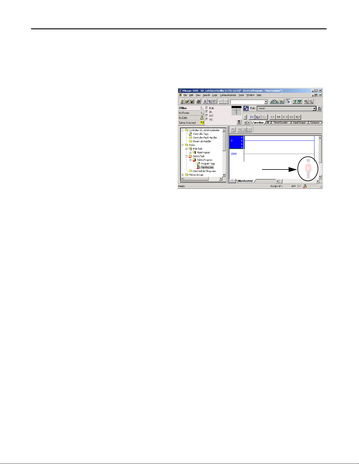
Chapter 6 Develop Safety Applications
TIP
Safety Routines
Safety Tags
Safety routines have all the attributes of standard routines, except that they exist
only in a safety program. At this time, only ladder diagram is supported for safety
routines.
A watermark feature visually distinguishes a safety routine from a standard
routine.
A tag is an area of a controller’s memory where data is stored. Tags are the basic
mechanism for allocating memory, referencing data from logic, and monitoring
data. Safety tags have all the attributes of standard tags with the addition of
mechanisms certified to provide SIL 3 data integrity.
When you create a tag, you assign the following properties:
• Name
• Description (optional)
• Ta g t yp e
• Data type
• Scope
• Class
• Style
• External Access
You can also specify if the tag value should be a constant.
To create a safety tag, open the New Tag dialog box by right-clicking Controller
Tags or Program Tags and choosing New Tag.
82 Rockwell Automation Publication 1756-UM022A-EN-P - November 2012
Page 83

Figure 24 - Creating a New Tag
Develop Safety Applications Chapter 6
Tag Type
Ta b l e 2 4 defines the four types of tags: base, alias, produced, and consumed.
Table 24 - Four Tag Types
Tag Type Description
Base These tags store values for use by logic within the project.
Alias A tag that references another tag. An alias tag can refer to another alias tag or a base tag. An
Produced A tag that a controller makes available for use by other controllers. A maximum of 15
Consumed A tag that receives the data of a produced tag. The data t ype of the consumed tag must match
alias tag can also refer to a component of another tag by referencing a member of a structure,
an array element, or a bit within a tag or member.
IMPORTANT: Aliasing between standard and safety tags is prohibited in safety applications.
Instead, standard tags can be mapped to safety tags using safety tag mapping. See Safety Tag
Mapping on page 92.
controllers can simultaneously consume (receive) the data. A produced tag sends its data to
one or more consuming tags without using logic. Produced tag data is sent at the RPI of the
consuming tag.
the data type of the produced tag. The requested packet interval (RPI) of the consumed tag
determines the period at which the data updates.
Rockwell Automation Publication 1756-UM022A-EN-P - November 2012 83
Page 84

Chapter 6 Develop Safety Applications
Data Type
The data type defines the type of data that the tag stores, such as bit or integer.
Data types can be combined to form structures. A structure provides a unique
data type that matches a specific need. Within a structure, each individual data
type is called a member. Like tags, members have a name and data type. You can
create your own structures, as user-defined data types.
Logix controllers contain predefined data types for use with specific instructions.
Only these data types are permitted for safety tags.
Table 25 - Valid Data Types for Safety Tags
AUX_VALVE_CONTROL DCI_STOP_TEST_MUTE MANUAL_VALVE_CONTROL
BOOL DINT MUTING_FOUR_SENSOR_BIDIR
CAM_PROFILE DIVERSE_INPUT MUTING_TWO_SENSOR_ASYM
CAMSHAFT_MONITOR EIGHT_POS_MODE_SELECTOR MUTING_TWO_SENSOR_SYM
CB_CONTINUOUS_MODE EMERGENC Y_STOP MOTION_INSTRUCTION
CB_CRANKSHAFT_POS_MONITOR ENABLE_PENDANT PHASE
CB_INCH_MODE EXT_ROUTINE_CONTROL PHASE_INSTRUCTION
CB_SINGLE_STROKE_MODE EXT_ROUTINE_PARAMETERS REDUNDANT_INPUT
CONFIGURABLE_ROUT FBD_BIT_FIELD_DISTRIBUTE REDUNDANT_OUTPUT
CONNECTION_STATUS FBD_CONVERT SAFETY_MAT
CONTROL FBD_COUNTER SERIAL_PORT_CONTROL
COUNTER FBD_LOGICAL SFC_ACTION
DCA_INPUT FBD_MASK_EQUAL SFC_STEP
DCAF_INPUT FBD_MASKED_MOVE SFC_STOP
DCI_MONITOR FBD_TIMER SINT
DCI_START FIVE_POS_MODE_SELECTOR STRING
DCI_STOP INT THRS_ENHANCED
DCI_STOP_TEST LIGHT_CURTAIN TIMER
DCI_STOP_TEST_LOCK MAIN_VALVE_CONTROL TWO_HAND_RUN_STATION
Scope
A tag’s scope determines where you can access the tag data. When you create a
tag, you define it as a controller tag (global data) or a program tag for a specific
safety or standard program (local data). Safety tags can be controller-scoped or
safety program-scoped.
84 Rockwell Automation Publication 1756-UM022A-EN-P - November 2012
Page 85

Develop Safety Applications Chapter 6
IMPORTANT
Controller-scoped Tags
When safety tags are controller-scoped, all programs have access to the safety
data. Tags must be controller-scoped if they are used in the following:
• More than one program in the project
• To produce or consume data
• To communicate with a PanelView/HMI terminal
• In safety tag mapping
See Safety Tag Mapping
Controller-scoped safety tags can be read, but not written to, by standard
routines.
Controller-scoped safety tags are readable by any standard routine. The
safety tag’s update rate is based on the safety task period.
Tags associated with Safety I/O and produced or consumed safety data must be
controller-scoped safety tags. For produced/consumed safety tags, you must
create a user-defined data type with the first member of the tag structure reserved
for the status of the connection. This member is a predefined data type called
CONNECTION_STATUS.
on page 92 for more information.
Table 26 - Additional Resources
Resource Description
Safety Connections on page 117 Provides more information on the
Logix5000 Controllers I/O and Tag Data Programming Manual,
publication 1756-PM004
CONNECTION_STATUS member
Provides instructions for creating user-defined
data types
Program-scoped Tags
When tags are program-scoped, the data is isolated from the other programs.
Reuse of program-scoped tag names is permitted between programs.
Safety-program-scoped safety tags can only be read by or written to via a safety
routine scoped in the same safety program.
Class
Tags can be classified as standard or safety. Tags classified as safety tags must have
a data type that is permitted for safety tags.
When you create program-scoped tags, the class is automatically specified,
depending upon whether the tag was created in a standard or safety program.
When you create controller-scoped tags, you must manually select the tag class.
Rockwell Automation Publication 1756-UM022A-EN-P - November 2012 85
Page 86

Chapter 6 Develop Safety Applications
Constant Value
When you designate a tag as a constant value, it cannot be modified by logic in
the controller, or by an external application such as an HMI. Constant value tags
cannot be forced.
The Logix Designer application can modify constant standard tags, and safety
tags provided a safety task signature is not present. Safety tags cannot be modified
if a safety task signature is present.
External Access
External Access defines the level of access that is allowed for external devices, such
as an HMI, to see or modify tag values. Access via the Logix Designer application
is not affected by this setting. The default value is read/write.
Table 27 - External Access Levels
External Access Setting Description
None Tags are not accessible from outside the controller.
Read Only Tags may be browsed or read, but not written to from outside the
controller.
Read/Write Standard tags may be browsed, read, and written to from outside the
controller.
Produced/Consumed Safety Tags
For alias tags, the External Access type is equal to the type configured for the base
target tag.
To transfer safety data between GuardLogix controllers, you use produced and
consumed safety tags. Produced and consumed tags require connections. The
default connection type for produced and consumed tags is unicast.
Table 28 - Produced and Consumed Connections
Tag Connection Description
Produced A GuardLogix controller can produce (send) safety tags to other 1756 or 1768 GuardLogix
controllers.
The producing controller uses a single connection for each consumer.
Consumed GuardLogix controllers can consume (receive) safety tags from other 1756 or 1768 GuardLogix
controllers.
Each consumed tag consumes one connection.
Produced and consumed safety tags are subject to the following restrictions:
• Only controller-scoped safety tags can be shared.
• Produced and consumed safety tags are limited to 128 bytes.
• Produced/consumed tag pairs must be of the same user-defined data type.
• The first member of that user-defined data type must be the predefined
CONNECTION_STATUS data type.
• The requested packet interval (RPI) of the consumed safety tag must
match the safety task period of the producing GuardLogix controller.
86 Rockwell Automation Publication 1756-UM022A-EN-P - November 2012
Page 87

Develop Safety Applications Chapter 6
Consum er Controller
Producer Controller
To properly configure produced and consumed safety tags to share data between
peer safety controllers, you must properly configure the peer safety controllers,
produce a safety tag, and consume a safety tag, as described below.
Configure the Peer Safety Controllers’ Safety Network Numbers
The peer safety controller is subject to the same configuration requirements as
the local safety controller. The peer safety controller must also have a safety
network number (SNN). The SNN of the peer safety controller depends upon
its placement in the system.
Table 29 - SNN and Controller Placement
Peer Safety Controller Location SNN
Placed in the local chassis GuardLogix controllers located in a common chassis
Placed in another chassis The controller must have a unique SNN.
Follow these steps to copy and paste the SNN.
should have the same SNN.
1. Add the producer controller to the consumer controller’s I/O tree.
2. In the producer controller’s project, right-click the producer controller and
choose Controller Properties.
Rockwell Automation Publication 1756-UM022A-EN-P - November 2012 87
Page 88

Chapter 6 Develop Safety Applications
3. Click to open the Safety Network Number dialog box.
4. Copy the producer controller’s SNN.
5. In the consumer controller’s project, right-click the producer controller
and choose Module Properties.
6. Click to open the Safety Network Number dialog box.
88 Rockwell Automation Publication 1756-UM022A-EN-P - November 2012
Page 89

Develop Safety Applications Chapter 6
Module Properties Dialog Box in Consumer ProjectProducer Controller Properties Dialog Box in Producer Project
Copy this SNN.
Paste the SNN here.
7. Paste the producer controller’s SNN into the SNN field and click OK.
The safety network numbers match.
Produce a Safety Tag
Follow this procedure to produce a safety tag.
1. In the producing controllers project, create a user-defined data type
defining the structure of the data to be produced.
Make sure that the first data member is of the
CONNECTION_STATUS data type.
2. Right-click Controller Tags and choose New Tag.
3. Set the type as Produced, the class as Safety, and the Data Type to the user-
defined type you created in step 1
.
4. Click Connection and enter the number of consumers.
Rockwell Automation Publication 1756-UM022A-EN-P - November 2012 89
Page 90

Chapter 6 Develop Safety Applications
TIP
5. Click Advanced if you want to change the type of connection by
unchecking ‘Allow Unicast Consumer Connections’.
6. Click OK.
Consume Safety Tag Data
Follow these steps to consume data produced by another controller.
1. In the consumer controller’s project, create a user-defined data type
identical to the one created in the producer project.
The user-defined type can be copied from the producer project
and pasted into the consumer project.
2. Right-click Controller Tags and choose New Tag.
3. Set the Type as Consumed, the Class as Safety, and the Data Type to the
user-defined data type you created in step 1
.
90 Rockwell Automation Publication 1756-UM022A-EN-P - November 2012
Page 91

Develop Safety Applications Chapter 6
Consumer’s Project Producer’s Project
4. Click Connection to open the Consumed Tag Connection dialog box.
5. Select the controller that produces the data.
6. Enter the name of the produced tag.
7. Click the Safety tab.
8. Enter the requested packet interval (RPI) for the connection in 1 ms
increments.
The default is 20 ms.
The RPI specifies the period at which data updates over a connection. The
RPI of the consumed safety tag must match the safety task period of the
producing safety project.
The Connection Reaction Time Limit is the maximum age of safety
packets on the associated connection. For simple timing constraints, an
acceptable Connection Reaction Time Limit can be achieved by adjusting
the RPI.
The Max Network Delay is the maximum observed transport delay from
the time the data was produced until the time the data was received. When
online, you can reset the Max Network Delay by clicking Reset Max.
Rockwell Automation Publication 1756-UM022A-EN-P - November 2012 91
Page 92
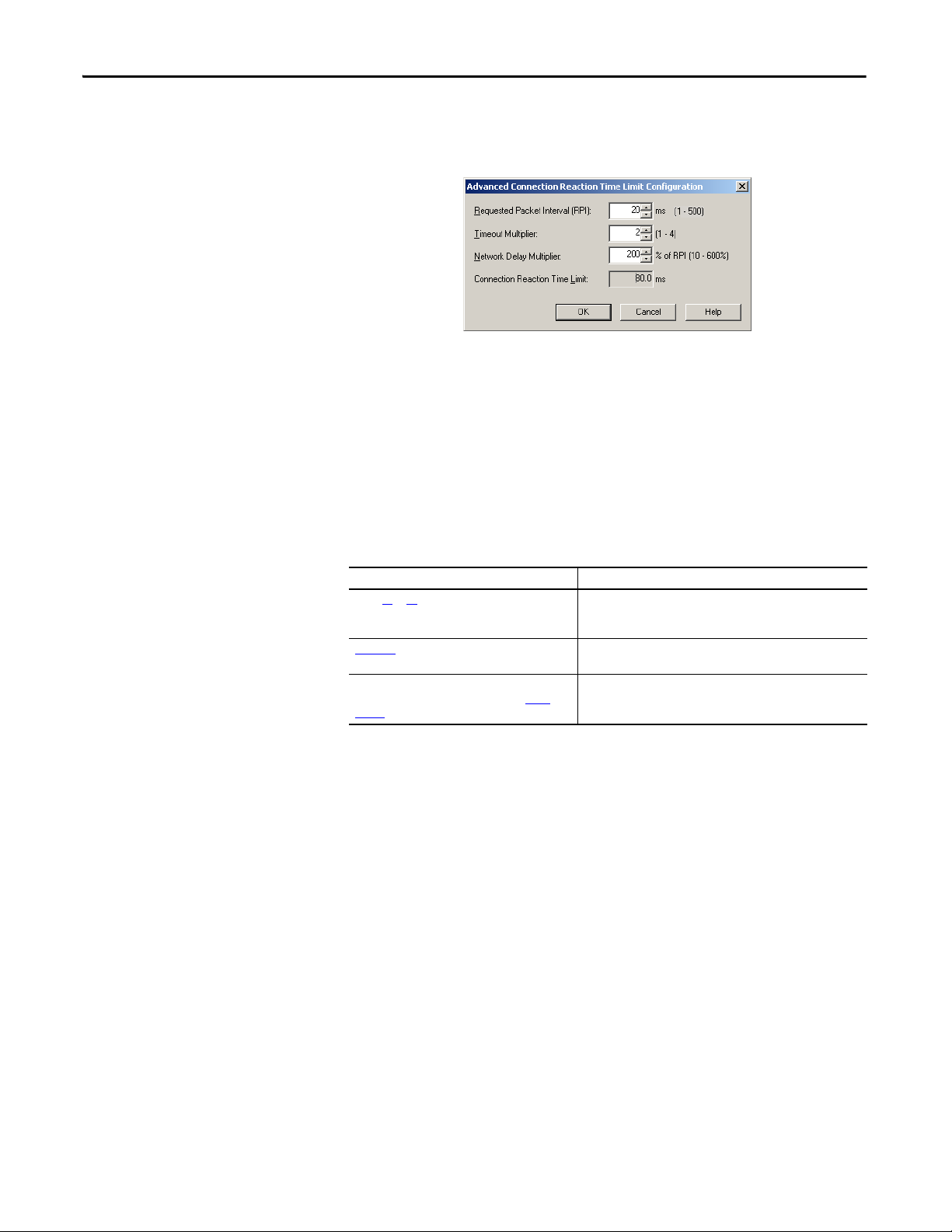
Chapter 6 Develop Safety Applications
9. If the Connection Reaction time limit is acceptable, click OK; or for more
complex requirements, click Advanced to set the Advanced Connection
Reaction Time Limit parameters.
The Timeout Multiplier determines the number of RPIs to wait for a
packet before declaring a connection timeout.
The Network Delay Multiplier defines the message transport time that is
enforced by the CIP Safety protocol. The Network Delay Multiplier
specifies the round-trip delay from the producer to the consumer and back
to the producer. You can use the Network Delay Multiplier to increase or
decrease the Connection Reaction Time Limit.
Safety Tag Mapping
Table 30 - Additional Resources
Resource Description
Pages 61
…65 Provides more information on setting the RPI and unde rstanding
Chapter
9 Contains information on the CONNECTION_STATUS predefined
Logix5000 Controllers Produced and Consumed
Tags Programming Manual, publication 1756-
PM011
how the Max. Network Delay, Timeout Multiplier, and Network
Delay Multipliers affect the Connection Reac tion Time
data type
Provides detailed information on using produced and consumed
tags
Controller-scoped standard tags cannot be directly accessed by a safety routine.
To allow standard tag data to be used within safety task routines, the GuardLogix
controllers provide a safety tag mapping feature that lets standard tag values be
copied into safety task memory.
92 Rockwell Automation Publication 1756-UM022A-EN-P - November 2012
Page 93

Develop Safety Applications Chapter 6
Restrictions
Safety tag mapping is subject to these restrictions:
• The safety tag and standard tag pair must be controller-scoped.
• The data types of the safety and standard tag pair must match.
• Alias tags are not allowed.
• Mapping must take place at the whole tag level. For example, myTimer.pre
is not allowed if myTimer is a TIMER tag.
• A mapping pair is one standard tag mapped to one safety tag.
• You may not map a standard tag to a safety tag that has been designated as
a constant.
• Tag mapping cannot be modified when the following is true:
– The project is safety-locked.
– A safety task signature exists.
– The keyswitch is in RUN position.
– A nonrecoverable safety fault exists.
– An invalid partnership exists between the primary controller and safety
partner.
ATTENTION: When using standard data in a safety routine, you are responsible for providing
a reliable means of ensuring that the data is used in an appropriate manner. Using standard
data in a safety tag does not make it safety data. You must not directly control a SIL 3/PLe
safety output with standard tag data.
Refer to the GuardLogix 5570 Controller Systems Safety Reference Manual, publication
1756-RM099
, for more information.
Create Tag Mapping Pairs
1. Choose Map Safety Tags from the Logic menu to open the Safety Tag
Mapping dialog box.
Rockwell Automation Publication 1756-UM022A-EN-P - November 2012 93
Page 94

Chapter 6 Develop Safety Applications
2. Add an existing tag to the Standard Tag Name or Safety Tag Name column
by typing the tag name into the cell or choosing a tag from the pull-down
menu.
Click the arrow to display a filtered tag browser dialog box. If you are in the
Standard Tag Name column, the browser shows only controller-scoped
standard tags. If you are in the Safety Tag Name column, the browser
shows controller-scoped safety tags.
3. Add a new tag to the Standard Tag Name or Safety Tag Name column by
right-clicking in the empty cell and selecting New Tag and typing the tag
name into the cell.
4. Right-click in the cell and choose New tagname, where tagname is the text
you entered in the cell.
Monitor Tag Mapping Status
The leftmost column of the Safety Tag Mapping dialog box indicates the status of
the mapped pair.
Table 31 - Ta g Map ping Stat us Icon s
Cell Contents Description
Empty Tag mapping is valid.
When offline, the X icon indicates that tag mapping is invalid. You can move to another row or
close the Safety Tag Mapping dialog box.
When online, an invalid tag map results in an error message explaining why the mapping is
invalid. You cannot move to another row or close the Safety Tag Mapping dialog box if a tag
mapping error exists.
Indicates the row that currently has the focus.
Represents the Create New Mapped Tag row.
Represents a pending edit.
(1)
(1) Tag mapping is also checked during project verification. Invalid tag mapping results in a project verification error.
For more information, see the tag mapping restrictions on page 93
94 Rockwell Automation Publication 1756-UM022A-EN-P - November 2012
.
Page 95

Develop Safety Applications Chapter 6
TIP
TIP
Safety Status Button
Safety Application Protection
You can protect your application program from unauthorized changes by safetylocking the controller and by generating and recording the safety task signature.
Safety-lock the Controller
The GuardLogix controller can be Safety-locked to protect safety-related control
components from modification. The Safety-lock feature applies only to safety
components, such as the safety task, safety programs, safety routines, safety AddOn Instructions, safety tags, Safety I/O, and the safety task signature.
The following actions are not permitted in the safety portion of the application
when the controller is safety-locked:
• Online/offline programming or editing (including safety Add-On
Instructions)
• Forcing Safety I/O
• Changing the inhibit state of Safety I/O or produced connections
• Safety data manipulation (except by safety routine logic)
• Generating or deleting the safety task signature
The text of the online bar’s safety status button indicates the safety-lock status.
The application tray also displays the following icons to indicate the safety
controller’s safety-lock status.
• = controller safety-locked
• = controller safety-unlocked
You can safety-lock the controller project regardless of whether you are online or
offline and regardless of whether you have the original source of the program.
However, no safety forces or pending online safety edits may be present.
Safety-locked or -unlocked status cannot be changed when the keyswitch is in the
RUN position.
Safety-lock or -unlock actions are logged in the controller log.
For more information on accessing the controller log, refer to Logix5000 Controllers
Controller Information and Status Programming Manual, publication 1756-PM015
.
Rockwell Automation Publication 1756-UM022A-EN-P - November 2012 95
Page 96

Chapter 6 Develop Safety Applications
TIP
You can Safety-lock and -unlock the controller from the Safety tab of the
Controller Properties dialog box or by choosing Tools>Safety>Safety Lock/
Unlo ck .
Figure 25 - Safety-locking the Controller
If you set a password for the safety-lock feature, you must type it in the Enter
Password field. Otherwise, click Lock.
You can also set or change the password from the Safety Lock dialog box. See
page 39
.
The safety-lock feature, described in this section, and standard security measures
in the Logix Designer application are applicable to GuardLogix controller
projects.
Refer to the Logix5000 Controllers Security Programming Manual, publication
1756-PM016
, for information on Logix Designer security features.
Generate a Safety Task Signature
Before verification testing, you must generate the safety task signature. You can
generate the safety task signature only when online with the safety-unlocked
GuardLogix controller in Program mode, and with no safety forces, pending
online safety edits, or safety faults. The safety status must be Safety Task OK.
In addition, you cannot generate a safety task signature if the controller is in Run
mode with run mode protection enabled.
You can view the safety status via the safety status button on the online bar (see
page 116
on page 97
) or on the Safety tab of the Controller Properties dialog box, as shown
.
96 Rockwell Automation Publication 1756-UM022A-EN-P - November 2012
Page 97

Develop Safety Applications Chapter 6
TIP
You can generate the safety task signature from the Safety tab of the Controller
Properties dialog box by clicking Generate. You can also choose
Tools>Safety>Generate Signature.
Figure 26 - Safety Tab
If a previous signature exists, you are prompted to overwrite it.
Safety task signature creation and deletion is logged in the controller log.
For more information on accessing the controller log, refer to Logix5000 Controllers
Controller Information and Status Programming Manual, publication 1756-PM015
When a safety task signature exists, the following actions are not permitted in the
safety portion of the application:
• Online/offline programming or editing (including safety Add-On
Instructions)
• Forcing Safety I/O
• Changing the inhibit state of Safety I/O or producer controllers
• Safety data manipulation (except by safety routine logic)
Copy the Safety Task Signature
You can use the Copy button to create a record of the safety task signature for use
in safety project documentation, comparison, and validation. Click Copy, to copy
the ID, Date, and Time components to the Windows clipboard.
.
Rockwell Automation Publication 1756-UM022A-EN-P - November 2012 97
Page 98

Chapter 6 Develop Safety Applications
IMPORTANT
Delete the Safety Task Signature
Click Delete to delete the safety task signature. The safety task signature cannot
be deleted when the following is true:
• The controller is safety-locked.
• The controller is in Run mode with the keyswitch in RUN.
• The controller is in Run or Remote Run mode with run mode protection
enabled.
ATT EN TI ON : If you delete the safety task signature, you must retest and
revalidate your system to meet SIL 3/PLe.
Refer to the GuardLogix 5570 Controller Systems Safety Reference Manual,
publication 1756-RM099
, for more information on SIL 3/PLe requirements.
Programming Restrictions
Restrictions limiting the availability of some menu items and features (that is, cut,
paste, delete, search and replace) are imposed by the Logix Designer application
to protect safety components from being modified whenever the following is
true:
• The controller is safety-locked.
• A safety task signature exists.
• Safety faults are present.
• Safety status is as follows:
– Partner missing
– Partner unavailable
– Hardware incompatible
– Firmware incompatible
If even one of these conditions apply, you may not do the following:
• Create or modify safety objects, including safety programs, safety routines,
safety tags, safety Add-On Instructions, and Safety I/O modules.
The scan times of the safety task and safety programs can be reset
when online.
• Apply forces to safety tags.
• Create new safety tag mappings.
• Modify or delete tag mappings.
• Modify or delete user-defined data types that are used by safety tags.
• Modify the controller name, description, chassis type, slot, and safety
network number.
• Modify or delete the safety task signature, when safety-locked.
98 Rockwell Automation Publication 1756-UM022A-EN-P - November 2012
Page 99

Go Online with the Controller
Top ic P ag e
Connecting the Controller to the Network 99
Understanding the Factors that Affect Going Online 101
Download 103
Upload 104
Go Online 106
Chapter 7
Connecting the Controller to the Network
If you have not done so, connect the controller to the network.
Table 32 - Communication Connections
For this type of
connection
USB USB 2.0 cable Make Communication Connections on
EtherNet/IP EtherNet/IP module in an open slot in the same
DeviceNet 1756-DNB module in an open slot in the same
ControlNet 1756-CN2 module in an open slot in the same
Use See
page 27
chassis as the controller
chassis as the controller
chassis as the controller
Connect Your EtherNet/IP Device and
Comput er on page 100
Connec t Yo ur ControlNet Commu nication
Module or DeviceNet Scanner and Your
Comput er on page 100
Rockwell Automation Publication 1756-UM022A-EN-P - November 2012 99
Page 100

Chapter 7 Go Online with the Controller
Ethernet
Commu nication
Module
Standard or Crossover Ethernet Cables with
RJ45 Connector
Ethernet Switch
Connect Your EtherNet/IP Device and Computer
WARNING: If you connect or disconnect the communication cable with
power applied to this module or any device on the network, an electrical
arc can occur. This could cause an explosion in hazardous location
installations.
Be sure that power is removed or the area is nonhazardous before
proceeding.
Connect your EtherNet/IP device and computer by using an Ethernet cable.
Figure 27 - Ethernet Connections
Connect Your ControlNet Communication Module or DeviceNet Scanner and Your Computer
To access the ControlNet or DeviceNet network, you can do either of the
following:
• Connect directly to the network.
• Connect to a serial or EtherNet/IP network and browse (bridge) to the
desired network. This requires no additional programming.
Configuring an EtherNet/IP, ControlNet, or DeviceNet Driver
For information on configuring a driver, refer to the appropriate publication:
• EtherNet/IP Modules in Logix5000 Control Systems, publication
ENET-UM001
• ControlNet Modules in Logix5000 Control Systems User Manual,
publication CNET-UM001
• DeviceNet Modules in Logix5000 Control Systems, publication
DNET-UM004
100 Rockwell Automation Publication 1756-UM022A-EN-P - November 2012
 Loading...