

Page 1

User Manual
ControlLogix System
Catalog Numbers 1756-L61, 1756-L62, 1756-L63, 1756-L63XT, 1756-L64, 1756-L65, 1756-L71, 1756-L72, 1756-L73,
1756-L73XT, 1756-L74, 1756-L75
Page 2
Important User Information
IMPORTANT
Solid-state equipment has operational characteristics differing from those of electromechanical equipment. Safety
Guidelines for the Application, Installation and Maintenance of Solid State Controls (publication SGI-1.1
your local Rockwell Automation® sales office or online at http://www.rockwellautomation.com/literature/
important differences between solid-state equipment and hard-wired electromechanical devices. Because of this difference,
and also because of the wide variety of uses for solid-state equipment, all persons responsible for applying this equipment
must satisfy themselves that each intended application of this equipment is acceptable.
In no event will Rockwell Automation, Inc. be responsible or liable for indirect or consequential damages resulting from the
use or application of this equipment.
The examples and diagrams in this manual are included solely for illustrative purposes. Because of the many variables and
requirements associated with any particular installation, Rockwell Automation, Inc. cannot assume responsibility or
liability for actual use based on the examples and diagrams.
No patent liability is assumed by Rockwell Automation, Inc. with respect to use of information, circuits, equipment, or
software described in this manual.
Reproduction of the contents of this manual, in whole or in part, without written permission of Rockwell Automation,
Inc., is prohibited.
Throughout this manual, when necessary, we use notes to make you aware of safety considerations.
available from
) describes some
WARNING: Identifies information about practices or circumstances that can cause an explosion in a hazardous environment,
which may lead to personal injury or death, property damage, or economic loss.
ATTENTION: Identifies information about practices or circumstances that can lead to personal injury or death, property
damage, or economic loss. Attentions help you identify a hazard, avoid a hazard, and recognize the consequence.
SHOCK HAZARD: Labels may be on or inside the equipment, for example, a drive or motor, to alert people that dangerous
voltage may be present.
BURN HAZARD: Labels may be on or inside the equipment, for example, a drive or motor, to alert people that surfaces may
reach dangerous temperatures.
Identifies information that is critical for successful application and understanding of the product.
Allen-Bradley, ArmorBlock, ArmorBlock MaXum, ArmorPOINT, Compact I/O, CompactLogix, ControlFLASH, ControlLogix, ControlLogix-XT, Data Highway Plus, DH+, DriveLogix, FactoryTalk, FLEX, FLEX Ex,
FlexLogix, GuardLogix, Guard PLC, Integrated Architecture, Kinetix, Logix5000, Logix5550, Logix Designer, MessageView, MicroLogix, PanelView, PhaseManager, PLC-5, POINT I/O, PowerFlex, RediSTATION,
Rockwell Automation, Rockwell Software, RSBizWare, RSFieldbus, RSL inx, RSLogix, R SNetWorx, RSView, RSWho, Series 9000, S LC, Studio 5000, Studio 5000 Automation & Engineering Design Environment, Studio
5000 Log ix Designer, and Stratix 8000 are trademarks of Rockwell Automation.
Trademarks not belonging to Rockwell Automation are property of their respective companies.
Page 3
Summary of Changes
This manual contains new and updated information. Changes throughout this
revision are marked by change bars, as shown to the right of this paragraph.
New and Updated Information
This table contains the changes made to this revision.
Top ic Pag e
Added DLR segment to EtherNet/IP Network Example. 86
Added DH+ Modules and Capabilities table. 95
Added Access the Module Object section to Develop Applications chapter. 160
Updated screenshots and descriptions for the Studio 5000 environment version 24. Throughout publication
Rockwell Automation Publication 1756-UM001O-EN-P - October 2014 3
Page 4

Summary of Changes
Notes:
4 Rockwell Automation Publication 1756-UM001O-EN-P - October 2014
Page 5

Table of Contents
Preface
Install the 1756-L7x Controller
Studio 5000 Environment . . . . . . . . . . . . . . . . . . . . . . . . . . . . . . . . . . . . . . . . 11
ControlLogix Controllers Overview . . . . . . . . . . . . . . . . . . . . . . . . . . . . . . . 11
Standard ControlLogix Controllers. . . . . . . . . . . . . . . . . . . . . . . . . . . . 12
Redundant ControlLogix Controllers. . . . . . . . . . . . . . . . . . . . . . . . . . 13
Extreme Environment ControlLogix Controllers . . . . . . . . . . . . . . . 13
Before You Begin . . . . . . . . . . . . . . . . . . . . . . . . . . . . . . . . . . . . . . . . . . . . . . . . 14
Required Software. . . . . . . . . . . . . . . . . . . . . . . . . . . . . . . . . . . . . . . . . . . . 14
Additional Resources . . . . . . . . . . . . . . . . . . . . . . . . . . . . . . . . . . . . . . . . . . . . . 15
Chapter 1
Before You Begin . . . . . . . . . . . . . . . . . . . . . . . . . . . . . . . . . . . . . . . . . . . . . . . . 21
1756-L7x Controller Parts . . . . . . . . . . . . . . . . . . . . . . . . . . . . . . . . . . . . . . . . 21
Parts Included with the 1756-L7x Controller . . . . . . . . . . . . . . . . . . . 21
Parts Available for Use with the 1756-L7x Controller . . . . . . . . . . . 22
1756-L7x Controller Installation . . . . . . . . . . . . . . . . . . . . . . . . . . . . . . . . . . 22
Insert the Controller into the Chassis. . . . . . . . . . . . . . . . . . . . . . . . . . . . . . 23
Insert the Key. . . . . . . . . . . . . . . . . . . . . . . . . . . . . . . . . . . . . . . . . . . . . . . . . . . . 24
Install the SD Card. . . . . . . . . . . . . . . . . . . . . . . . . . . . . . . . . . . . . . . . . . . . . . . 25
Remove the SD Card . . . . . . . . . . . . . . . . . . . . . . . . . . . . . . . . . . . . . . . . . . . . . 26
Install the ESM . . . . . . . . . . . . . . . . . . . . . . . . . . . . . . . . . . . . . . . . . . . . . . . . . . 28
Uninstall the ESM . . . . . . . . . . . . . . . . . . . . . . . . . . . . . . . . . . . . . . . . . . . . . . . 29
Install the 1756-L6x Controller
Start Using the Controller
Chapter 2
Before You Begin . . . . . . . . . . . . . . . . . . . . . . . . . . . . . . . . . . . . . . . . . . . . . . . . 35
1756-L6x Controller Parts . . . . . . . . . . . . . . . . . . . . . . . . . . . . . . . . . . . . . . . . 35
Parts Not Included with the 1756-L6x Controller. . . . . . . . . . . . . . . 35
1756-L6x Controller Installation . . . . . . . . . . . . . . . . . . . . . . . . . . . . . . . . . . 36
CompactFlash Card Installation and Removal. . . . . . . . . . . . . . . . . . . . . . 36
Battery Connection and Replacement . . . . . . . . . . . . . . . . . . . . . . . . . . . . . 39
Insert the Controller into the Chassis. . . . . . . . . . . . . . . . . . . . . . . . . . . . . . 42
Remove the Controller from the Chassis . . . . . . . . . . . . . . . . . . . . . . . . . . . 44
Chapter 3
Make Connections . . . . . . . . . . . . . . . . . . . . . . . . . . . . . . . . . . . . . . . . . . . . . . . 45
1756-L7x Connection Options. . . . . . . . . . . . . . . . . . . . . . . . . . . . . . . . 45
1756-L6x Connection Options. . . . . . . . . . . . . . . . . . . . . . . . . . . . . . . . 46
Connect to the 1756-L7x Controller . . . . . . . . . . . . . . . . . . . . . . . . . . . . . . 46
Configure the USB Driver . . . . . . . . . . . . . . . . . . . . . . . . . . . . . . . . . . . . 47
Connect to the 1756-L6x Controller . . . . . . . . . . . . . . . . . . . . . . . . . . . . . . 49
Configure the Serial Driver. . . . . . . . . . . . . . . . . . . . . . . . . . . . . . . . . . . . 50
Upgrade Controller Firmware. . . . . . . . . . . . . . . . . . . . . . . . . . . . . . . . . . . . . 52
Determine Required Controller Firmware. . . . . . . . . . . . . . . . . . . . . . 52
Obtain Controller Firmware . . . . . . . . . . . . . . . . . . . . . . . . . . . . . . . . . . 53
Use ControlFLASH Software to Upgrade Firmware . . . . . . . . . . . . 53
Rockwell Automation Publication 1756-UM001O-EN-P - October 2014 5
Page 6

Table of Contents
Use AutoFlash to Upgrade Firmware. . . . . . . . . . . . . . . . . . . . . . . . . . . 56
Set the Communication Path. . . . . . . . . . . . . . . . . . . . . . . . . . . . . . . . . . . . . . 58
Go Online with the Controller . . . . . . . . . . . . . . . . . . . . . . . . . . . . . . . . . . . . 58
Download to the Controller. . . . . . . . . . . . . . . . . . . . . . . . . . . . . . . . . . . . . . . 59
Use the Who Active Dialog Box to Download . . . . . . . . . . . . . . . . . . 59
Use the Controller Status Menu to Download . . . . . . . . . . . . . . . . . . 60
Upload from the Controller. . . . . . . . . . . . . . . . . . . . . . . . . . . . . . . . . . . . . . . 60
Use the Who Active Dialog Box to Upload . . . . . . . . . . . . . . . . . . . . . 60
Use the Controller Status Menu to Upload . . . . . . . . . . . . . . . . . . . . . 61
Choose the Controller Operation Mode . . . . . . . . . . . . . . . . . . . . . . . . . . . 62
Use the Mode Switch to Change the Operation Mode . . . . . . . . . . . 62
Use Logix Designer to Change the Operation Mode . . . . . . . . . . . . . 64
Load or Store to the Memory Card . . . . . . . . . . . . . . . . . . . . . . . . . . . . . . . . 65
Store to the Memory Card. . . . . . . . . . . . . . . . . . . . . . . . . . . . . . . . . . . . . 65
Load from the Memory Card . . . . . . . . . . . . . . . . . . . . . . . . . . . . . . . . . . 68
Other Memory Card Tasks . . . . . . . . . . . . . . . . . . . . . . . . . . . . . . . . . . . . 70
Use ControlLogix Energy Storage Modules (ESMs) . . . . . . . . . . . . . . . . . 70
Save the Program to On-board NVS Memory . . . . . . . . . . . . . . . . . . . 71
Clear the Program from On-board NVS Memory . . . . . . . . . . . . . . . 71
Estimate the ESM Support of the WallClockTime . . . . . . . . . . . . . . . . . . 72
Maintain the Battery (Only 1756-L6x Controllers) . . . . . . . . . . . . . . . . . 72
Check the Battery Status . . . . . . . . . . . . . . . . . . . . . . . . . . . . . . . . . . . . . . 72
1756-BA1 or 1756-BATA Battery Life . . . . . . . . . . . . . . . . . . . . . . . . . 73
1756-BATM Battery Module and Battery Life . . . . . . . . . . . . . . . . . . 74
Estimate 1756-BA2 Battery Life . . . . . . . . . . . . . . . . . . . . . . . . . . . . . . . 75
Estimate 1756-BA2 Battery Life After Warnings . . . . . . . . . . . . . . . . 76
Battery Storage and Disposal. . . . . . . . . . . . . . . . . . . . . . . . . . . . . . . . . . . 77
Chapter 4
ControlLogix System and Controllers
ControlLogix System . . . . . . . . . . . . . . . . . . . . . . . . . . . . . . . . . . . . . . . . . . . . . 79
Configuration Options. . . . . . . . . . . . . . . . . . . . . . . . . . . . . . . . . . . . . . . . 79
Design a ControlLogix System. . . . . . . . . . . . . . . . . . . . . . . . . . . . . . . . . . . . . 81
ControlLogix Controller Features . . . . . . . . . . . . . . . . . . . . . . . . . . . . . . . . . 82
System, Communication, and Programming Features. . . . . . . . . . . . 82
Memory Options . . . . . . . . . . . . . . . . . . . . . . . . . . . . . . . . . . . . . . . . . . . . . 83
Electronic Keying. . . . . . . . . . . . . . . . . . . . . . . . . . . . . . . . . . . . . . . . . . . . . 84
Chapter 5
Communication Networks
6 Rockwell Automation Publication 1756-UM001O-EN-P - October 2014
Networks Available. . . . . . . . . . . . . . . . . . . . . . . . . . . . . . . . . . . . . . . . . . . . . . . 85
EtherNet/IP Network Communication . . . . . . . . . . . . . . . . . . . . . . . . . . . . 86
ControlLogix EtherNet/IP Module Features. . . . . . . . . . . . . . . . . . . . 86
ControlLogix EtherNet/IP Communication Modules . . . . . . . . . . . 87
Software for EtherNet/IP Networks. . . . . . . . . . . . . . . . . . . . . . . . . . . . 88
Connections Over an EtherNet/IP Network. . . . . . . . . . . . . . . . . . . . 88
Double Data Rate (DDR) Backplane Communication. . . . . . . . . . . 88
ControlNet Network Communication. . . . . . . . . . . . . . . . . . . . . . . . . . . . . 89
Page 7

Table of Contents
ControlLogix ControlNet Module Features . . . . . . . . . . . . . . . . . . . . 90
ControlLogix ControlNet Modules. . . . . . . . . . . . . . . . . . . . . . . . . . . . 91
Software for ControlNet Networks . . . . . . . . . . . . . . . . . . . . . . . . . . . . 91
Connections Over a ControlNet Network . . . . . . . . . . . . . . . . . . . . . 92
DeviceNet Network Communication. . . . . . . . . . . . . . . . . . . . . . . . . . . . . . 92
ControlLogix DeviceNet Module Features . . . . . . . . . . . . . . . . . . . . . 93
ControlLogix DeviceNet Bridge Module and Linking Devices . . . 94
Software for DeviceNet Networks . . . . . . . . . . . . . . . . . . . . . . . . . . . . . 94
Connections Over DeviceNet Networks . . . . . . . . . . . . . . . . . . . . . . . 94
ControlLogix DeviceNet Module Memory . . . . . . . . . . . . . . . . . . . . . 94
Data Highway Plus (DH+) Network Communication . . . . . . . . . . . . . . 95
Communicate Over a DH+ Network . . . . . . . . . . . . . . . . . . . . . . . . . . 96
Universal Remote I/O (RIO) Communication . . . . . . . . . . . . . . . . . . . . . 97
Communicate Over a Universal Remote I/O Network . . . . . . . . . . 97
Foundation Fieldbus Communication . . . . . . . . . . . . . . . . . . . . . . . . . . . . . 98
HART Communication. . . . . . . . . . . . . . . . . . . . . . . . . . . . . . . . . . . . . . . . . . 99
Chapter 6
Serial Communication on 1756-L6x
Controllers
Manage Controller Communication
1756-L6x Controller Serial Port. . . . . . . . . . . . . . . . . . . . . . . . . . . . . . . . . . 102
ControlLogix Chassis Serial Communication Options . . . . . . . . . 102
Communication with Serial Devices . . . . . . . . . . . . . . . . . . . . . . . . . . . . . . 103
DF1 Master Protocol . . . . . . . . . . . . . . . . . . . . . . . . . . . . . . . . . . . . . . . . . . . . 104
DF1 Point to Point Protocol . . . . . . . . . . . . . . . . . . . . . . . . . . . . . . . . . . . . . 105
DF1 Radio Modem Protocol . . . . . . . . . . . . . . . . . . . . . . . . . . . . . . . . . . . . . 106
DF1 Radio Modem Advantages . . . . . . . . . . . . . . . . . . . . . . . . . . . . . . 106
DF1 Radio Modem Limitations . . . . . . . . . . . . . . . . . . . . . . . . . . . . . . 107
DF1 Radio Modem Protocol Parameters . . . . . . . . . . . . . . . . . . . . . . 108
DF1 Slave Protocol. . . . . . . . . . . . . . . . . . . . . . . . . . . . . . . . . . . . . . . . . . . . . . 109
DH-485 Protocol . . . . . . . . . . . . . . . . . . . . . . . . . . . . . . . . . . . . . . . . . . . . . . . 110
ASCII Protocol . . . . . . . . . . . . . . . . . . . . . . . . . . . . . . . . . . . . . . . . . . . . . . . . . 112
Configure the 1756-L6x Controller for Serial Communication . . . . . 113
Broadcast Messages Over a Serial Port. . . . . . . . . . . . . . . . . . . . . . . . . . . . . 115
Configure Controller Serial Port Properties . . . . . . . . . . . . . . . . . . . 115
Program the Message Instruction . . . . . . . . . . . . . . . . . . . . . . . . . . . . . 117
Modbus Support . . . . . . . . . . . . . . . . . . . . . . . . . . . . . . . . . . . . . . . . . . . . . . . . 118
Chapter 7
Connection Overview . . . . . . . . . . . . . . . . . . . . . . . . . . . . . . . . . . . . . . . . . . . 119
Produce and Consume (Interlock) Data . . . . . . . . . . . . . . . . . . . . . . . . . . 119
Connection Requirements of a Produced or Consumed Tag . . . . 120
Send and Receive Messages. . . . . . . . . . . . . . . . . . . . . . . . . . . . . . . . . . . . . . . 121
Determine Whether to Cache Message Connections . . . . . . . . . . . 122
Calculate Connection Use . . . . . . . . . . . . . . . . . . . . . . . . . . . . . . . . . . . . . . . 122
Local Connections . . . . . . . . . . . . . . . . . . . . . . . . . . . . . . . . . . . . . . . . . . 123
Remote Connections . . . . . . . . . . . . . . . . . . . . . . . . . . . . . . . . . . . . . . . . 123
Connections Example . . . . . . . . . . . . . . . . . . . . . . . . . . . . . . . . . . . . . . . 124
Rockwell Automation Publication 1756-UM001O-EN-P - October 2014 7
Page 8

Table of Contents
Chapter 8
I/O Modules
Develop Motion Applications
Selecting ControlLogix
I/O Modules. . . . . . . . . . . . . . . . . . . . . . . . . . . . . . . . . . . . . . . . . . . . . . . . . . . . 127
Local I/O Modules . . . . . . . . . . . . . . . . . . . . . . . . . . . . . . . . . . . . . . . . . . . . . . 127
Add Local I/O to the I/O Configuration . . . . . . . . . . . . . . . . . . . . . . 128
Remote I/O Modules . . . . . . . . . . . . . . . . . . . . . . . . . . . . . . . . . . . . . . . . . . . . 129
Add Remote I/O to the I/O Configuration . . . . . . . . . . . . . . . . . . . . 130
Distributed I/O . . . . . . . . . . . . . . . . . . . . . . . . . . . . . . . . . . . . . . . . . . . . . . . . . 132
Add Distributed I/O to the I/O Configuration . . . . . . . . . . . . . . . . 133
Reconfigure an I/O Module . . . . . . . . . . . . . . . . . . . . . . . . . . . . . . . . . . . . . 135
Reconfigure an I/O Module Via the Module Properties . . . . . . . . . 135
Reconfigure an I/O Module Via a Message Instruction. . . . . . . . . . 137
Add to the I/O Configuration While Online . . . . . . . . . . . . . . . . . . . . . . 137
Modules and Devices that Can be Added While Online. . . . . . . . . 137
Online Additions - ControlNet Considerations . . . . . . . . . . . . . . . . 138
Online Additions—EtherNet/IP Considerations . . . . . . . . . . . . . . 141
Determine When Data is Updated. . . . . . . . . . . . . . . . . . . . . . . . . . . . . . . . 141
Chapter 9
Motion Control Options . . . . . . . . . . . . . . . . . . . . . . . . . . . . . . . . . . . . . . . . 143
Motion Overview . . . . . . . . . . . . . . . . . . . . . . . . . . . . . . . . . . . . . . . . . . . . . . . 144
Obtain Axis Information. . . . . . . . . . . . . . . . . . . . . . . . . . . . . . . . . . . . . . . . . 144
Program Motion Control . . . . . . . . . . . . . . . . . . . . . . . . . . . . . . . . . . . . . . . . 145
Example . . . . . . . . . . . . . . . . . . . . . . . . . . . . . . . . . . . . . . . . . . . . . . . . . . . . 145
Develop Applications
Chapter 10
Elements of a Control Application. . . . . . . . . . . . . . . . . . . . . . . . . . . . . . . . 147
Tasks. . . . . . . . . . . . . . . . . . . . . . . . . . . . . . . . . . . . . . . . . . . . . . . . . . . . . . . . . . . 148
Task Priority . . . . . . . . . . . . . . . . . . . . . . . . . . . . . . . . . . . . . . . . . . . . . . . . 151
Programs . . . . . . . . . . . . . . . . . . . . . . . . . . . . . . . . . . . . . . . . . . . . . . . . . . . . . . . 151
Scheduled and Unscheduled Programs . . . . . . . . . . . . . . . . . . . . . . . . 153
Routines. . . . . . . . . . . . . . . . . . . . . . . . . . . . . . . . . . . . . . . . . . . . . . . . . . . . . . . . 154
Parameters and Local Tags . . . . . . . . . . . . . . . . . . . . . . . . . . . . . . . . . . . . . . . 155
Extended Properties . . . . . . . . . . . . . . . . . . . . . . . . . . . . . . . . . . . . . . . . . 156
Access Extended Properties in Logic. . . . . . . . . . . . . . . . . . . . . . . . . . . 156
Programming Languages . . . . . . . . . . . . . . . . . . . . . . . . . . . . . . . . . . . . . . . . . 158
Add-On Instructions . . . . . . . . . . . . . . . . . . . . . . . . . . . . . . . . . . . . . . . . . . . . 159
Access the Module Object. . . . . . . . . . . . . . . . . . . . . . . . . . . . . . . . . . . . . . . . 160
Create the Add-On Instruction . . . . . . . . . . . . . . . . . . . . . . . . . . . . . . . 160
Monitoring Controller Status . . . . . . . . . . . . . . . . . . . . . . . . . . . . . . . . . . . . 161
Monitoring I/O Connections . . . . . . . . . . . . . . . . . . . . . . . . . . . . . . . . . . . . 162
Determine if I/O Communication has Timed Out . . . . . . . . . . . . . 163
Determine if I/O Communication to a Specific I/O Module has
Timed Out. . . . . . . . . . . . . . . . . . . . . . . . . . . . . . . . . . . . . . . . . . . . . . . . . . 163
Interrupt the Execution of Logic and Execute the Fault Handler. 164
System Overhead Time Slice . . . . . . . . . . . . . . . . . . . . . . . . . . . . . . . . . . . . . 165
8 Rockwell Automation Publication 1756-UM001O-EN-P - October 2014
Page 9

Table of Contents
Configure the System Overhead Time Slice. . . . . . . . . . . . . . . . . . . . 166
Sample Controller Projects. . . . . . . . . . . . . . . . . . . . . . . . . . . . . . . . . . . 167
Chapter 11
Using the PhaseManager Tool
Redundant Systems
Troubleshoot the Module
PhaseManager Overview. . . . . . . . . . . . . . . . . . . . . . . . . . . . . . . . . . . . . . . . . 169
Minimum System Requirements . . . . . . . . . . . . . . . . . . . . . . . . . . . . . . . . . 171
State Model Overview . . . . . . . . . . . . . . . . . . . . . . . . . . . . . . . . . . . . . . . . . . . 171
How Equipment Changes States. . . . . . . . . . . . . . . . . . . . . . . . . . . . . . 172
Manually Change States . . . . . . . . . . . . . . . . . . . . . . . . . . . . . . . . . . . . . 173
PhaseManager Tool versus Other State Models . . . . . . . . . . . . . . . . . . . . 174
Equipment Phase Instructions . . . . . . . . . . . . . . . . . . . . . . . . . . . . . . . . . . . 174
Chapter 12
ControlLogix Redundancy Overview . . . . . . . . . . . . . . . . . . . . . . . . . . . . . 175
System Requirements. . . . . . . . . . . . . . . . . . . . . . . . . . . . . . . . . . . . . . . . . . . . 177
System Considerations . . . . . . . . . . . . . . . . . . . . . . . . . . . . . . . . . . . . . . . . . . 178
Enhanced Versus Standard Redundancy. . . . . . . . . . . . . . . . . . . . . . . 179
Build a Redundant System . . . . . . . . . . . . . . . . . . . . . . . . . . . . . . . . . . . . . . . 179
ControlNet Considerations in Redundant Systems . . . . . . . . . . . . . . . . 180
EtherNet/IP Considerations in Redundant Systems . . . . . . . . . . . . . . . 180
IP Address Swapping . . . . . . . . . . . . . . . . . . . . . . . . . . . . . . . . . . . . . . . . 180
Redundancy and Scan Time. . . . . . . . . . . . . . . . . . . . . . . . . . . . . . . . . . . . . . 181
Appendix A
Use Logix Designer Application for Troubleshooting . . . . . . . . . . . . . . 183
Fault Type Determination . . . . . . . . . . . . . . . . . . . . . . . . . . . . . . . . . . . 185
1756-L7x Controller Status Display and Indicators . . . . . . . . . . . . . . . . 186
1756-L7x Controller Status Display . . . . . . . . . . . . . . . . . . . . . . . . . . . . . . 186
General Status Messages . . . . . . . . . . . . . . . . . . . . . . . . . . . . . . . . . . . . . 186
Fault Messages . . . . . . . . . . . . . . . . . . . . . . . . . . . . . . . . . . . . . . . . . . . . . . 187
Major Fault Messages . . . . . . . . . . . . . . . . . . . . . . . . . . . . . . . . . . . . . . . . 189
I/O Fault Codes. . . . . . . . . . . . . . . . . . . . . . . . . . . . . . . . . . . . . . . . . . . . . 191
1756-L7x Controller Status Indicators. . . . . . . . . . . . . . . . . . . . . . . . . . . . 195
RUN Indicator. . . . . . . . . . . . . . . . . . . . . . . . . . . . . . . . . . . . . . . . . . . . . . 195
FORCE Indicator . . . . . . . . . . . . . . . . . . . . . . . . . . . . . . . . . . . . . . . . . . . 195
SD Indicator . . . . . . . . . . . . . . . . . . . . . . . . . . . . . . . . . . . . . . . . . . . . . . . . 195
OK Indicator . . . . . . . . . . . . . . . . . . . . . . . . . . . . . . . . . . . . . . . . . . . . . . . 196
1756-L6x Status Indicators . . . . . . . . . . . . . . . . . . . . . . . . . . . . . . . . . . . . . . 196
RUN Indicator. . . . . . . . . . . . . . . . . . . . . . . . . . . . . . . . . . . . . . . . . . . . . . 196
I/O Indicator . . . . . . . . . . . . . . . . . . . . . . . . . . . . . . . . . . . . . . . . . . . . . . . 197
FORCE Indicator . . . . . . . . . . . . . . . . . . . . . . . . . . . . . . . . . . . . . . . . . . . 197
RS232 Indicator. . . . . . . . . . . . . . . . . . . . . . . . . . . . . . . . . . . . . . . . . . . . . 197
BAT Indicator . . . . . . . . . . . . . . . . . . . . . . . . . . . . . . . . . . . . . . . . . . . . . . 198
OK Indicator . . . . . . . . . . . . . . . . . . . . . . . . . . . . . . . . . . . . . . . . . . . . . . . 198
Rockwell Automation Publication 1756-UM001O-EN-P - October 2014 9
Page 10

Table of Contents
Appendix B
History of Changes
Index
1756-UM001N-EN-P, November, 2012 . . . . . . . . . . . . . . . . . . . . . . . . . . 200
1756-UM001M-EN-P, February 2012 . . . . . . . . . . . . . . . . . . . . . . . . . . . . 200
1756-UM001L-EN-P, November 2011 . . . . . . . . . . . . . . . . . . . . . . . . . . . 200
1756-UM001K-EN-P, May 2011. . . . . . . . . . . . . . . . . . . . . . . . . . . . . . . . . 200
1756-UM001J-EN-P, July 2010 . . . . . . . . . . . . . . . . . . . . . . . . . . . . . . . . . . 201
1756-UM001I-EN-P, January 2007. . . . . . . . . . . . . . . . . . . . . . . . . . . . . . . 201
1756-UM001H-EN-P, July 2008 . . . . . . . . . . . . . . . . . . . . . . . . . . . . . . . . . 201
1756-UM001G-EN-P, January 2007. . . . . . . . . . . . . . . . . . . . . . . . . . . . . . 201
1756-UM001F-EN-P, May 2005 . . . . . . . . . . . . . . . . . . . . . . . . . . . . . . . . . 201
1756-UM001E-EN-P, August 2002 . . . . . . . . . . . . . . . . . . . . . . . . . . . . . . 202
1756-UM001D-EN-P . . . . . . . . . . . . . . . . . . . . . . . . . . . . . . . . . . . . . . . . . . . 202
1756-UM001C-EN-P, June 2001 . . . . . . . . . . . . . . . . . . . . . . . . . . . . . . . . 202
1756-UM001B-EN-P, November 2000 . . . . . . . . . . . . . . . . . . . . . . . . . . . 202
10 Rockwell Automation Publication 1756-UM001O-EN-P - October 2014
Page 11
Preface
Studio 5000 Environment
The Studio 5000 Automation Engineering & Design Environment™ combines
engineering and design elements into a common environment. The first element
in the Studio 5000® environment is the Studio 5000 Logix Designer™ application.
The Logix Designer application is the rebranding of RSLogix™ 5000 software
and continues to be the product to program Logix5000™ controllers for discrete,
process, batch, motion, safety, and drive-based solutions.
ControlLogix Controllers Overview
The Studio 5000 environment is the foundation for the future of
Rockwell Automation® engineering design tools and capabilities. This
environment is the one place for design engineers to develop the elements of their
control system.
There are three types of ControlLogix® controllers available. These types include
the following:
• Standard ControlLogix controllers
• Extreme environment ControlLogix controllers
• GuardLogix® controllers
This manual explains how to use standard and extreme environment
ControlLogix controllers.
Rockwell Automation Publication 1756-UM001O-EN-P - October 2014 11
Page 12
Preface
For detailed information about GuardLogix safety controllers, see the following
publications.
Resource Description
GuardLogix 5570 Controllers User Manual, publication
1756-UM022
GuardLogix 5570 Controller System Safety Reference
Manual, publication 1756-RM099
GuardLogix Controllers User Manual, publication
1756-UM020
GuardLogix Controller Systems Safety Reference Manual,
publication 1756-RM093
GuardLogix Safety Application Instruction Set Safety
Reference Manual, publication 1756-RM095
Provides information on how to install, configure, and
operate GuardLogix 5570 controllers in Studio 5000,
version 21 or later projects.
Provides information on how to meet safety application
requirements for GuardLogix 5570 controllers in Studio
5000, version 21 or later projects.
Provides information on how to install, configure, and
operate GuardLogix 5560 and GuardLogix 5570 controllers
in RSLogix 5000, version 20 or earlier projects.
Provides information on how to meet safety application
requirements for GuardLogix 5560 and GuardLogix 5570
controllers in RSLogix 5000, version 20 or earlier projects.
Provides programmers with details about the GuardLogix
safety application instruction set.
Standard ControlLogix Controllers
Two lines of standard ControlLogix controllers are now available. These
controllers are identified as 1756-L6x controllers and 1756-L7x controllers
according to abbreviations of their full catalog numbers.
Table 1 - ControlLogix Catalog Numbers
Abbreviated Cat. No. Cat. No.
1756-L6x 1756-L61, 1756-L62,1756-L63, 1756-L64,1756-L65
1756-L7x 1756-L71, 1756-L72, 1756-L73,1756-L74, 1756-L75
The standard ControlLogix controllers share many similar features, but also have
some differences. Table 2 provides a brief overview the differences between the
controllers. For further details about these features and differences, see the
appropriate chapters of this manual.
Table 2 - Differences between 1756-L7x and 1756-L6x Controllers
Feature 1756-L7x 1756-L6x
Clock support and backup used for
memory retention at powerdown
Communication ports (built-in) USB Serial
Connections, controller 500 250
Memory, nonvolatile Secure Digital (SD) card CompactFlash card
Status display and status indicators Scrolling status display and four
Unconnected buffer defaults 20 (40, max) 10 (40, max)
Energy Storage Module (ESM) Battery
Six status indicators
status indicators
For information on using ControlLogix controllers in SIL 2 applications, see the
Using ControlLogix in SIL 2 Applications Safety Reference Manual, publication
1756-RM001
12 Rockwell Automation Publication 1756-UM001O-EN-P - October 2014
.
Page 13

Preface
Redundant ControlLogix Controllers
Certain ControlLogix controllers are also supported for use in redundant
systems. For more information about controllers and redundant systems, see
Chapter 12
.
Extreme Environment ControlLogix Controllers
The extreme environment ControlLogix controllers, catalog numbers
1756-L73XT and 1756-L63XT, provide the same functionality as the 1756-L73
and 1756-L63 controllers, but are designed to withstand temperatures
-25…70 °C (-13…158 °F).
Rockwell Automation Publication 1756-UM001O-EN-P - October 2014 13
Page 14
Preface
Before You Begin
Before you begin using your ControlLogix controller, verify that you have the
applications that are required to configure and program the controller.
Required Software
Use Ta b l e 3 to identify the minimum software versions that are required to use
your ControlLogix controller.
Table 3 - Required Software for Controller Use
Cat. No. Studio 5000 Environment RSLogix 5000 Software RSLinx® Classic
1756-L61/A — Version 12.06.00 or later Any version
1756-L61/B — Version 13.04.00 or later
1756-L62/A — Version 12.06.00 or later
1756-L62/B — Version 13.04.00 or later
1756-L63/A — • If not using a CompactFlash
card, version 10.07.00 or
later
• If using a CompactFlash
card, version 11.16.00 or
later
1756-L63/B — Version 13.04.00 or later
1756-L63XT/B — Version 13.04.00 or later Version 2.55.00 or later
1756-L64/B — Version 16.03.00 or later Any version
1756-L65/B — Version 17.01.02 or later
1756-L71 Version 21.00.00 or later Version 20.01.02 Version 2.59.00 or later
1756-L72 Version 21.00.00 or later Version 19.01.00 or later Version 2.57.00 or later
1756-L73 Version 21.00.00 or later Version 19.01.00 or later
1756-L73XT Version 21.00.00 or later Version 19.01.00 or later
1756-L74 Version 21.00.00 or later Version 19.01.00 or later
1756-L75 Version 21.00.00 or later Version 19.01.00 or later
14 Rockwell Automation Publication 1756-UM001O-EN-P - October 2014
Page 15
Preface
Additional Resources
These documents contain additional information concerning related products
from Rockwell Automation.
Resource Description
1756 ControlLogix Controllers Technical Data, publication
1756-TD001
1756 ControlLogix I/O Specifications Technical Data,
publication 1756-TD002
ControlLogix Analog I/O Modules User Manual,
publication 1756-UM009
ControlLogix Battery Module Installation Instructions,
publication 1756-IN576
ControlLogix Chassis and Power Supply Installation
Instructions, publication 1756-IN005
ControlLogix Configurable Flowmeter Module User
Manual, publication 1756-UM010
ControlLogix Data Highway Plus-Remote I/O
Communication Interface Module User Manual,
publication 1756-UM514
ControlLogix DH-485 Communication Module User
Manual, publication 1756-UM532
ControlLogix Digital I/O Modules User Manual, publication
1756-UM058
ControlLogix Enhanced Redundancy System User Manual,
publication 1756-UM535
ControlLogix HART Analog I/O Modules User Manual,
publication 1756-UM533
ControlLogix High-speed Analog I/O Module User Manual,
publication 1756-UM005
ControlLogix High-speed Counter Module User Manual,
publication 1756-UM007
ControlLogix Low-speed Counter Module User Manual,
publication 1756-UM536
ControlLogix Pe er I/O Control Appl ication Technique,
publication 1756-AT016
ControlLogix Programmable Limit Switch Module User
Manual, publication 1756-UM002
ControlLogix Redundancy System User Manual,
publication 1756-UM523
ControlLogix Remote I/O Communication Module User
Manual, publication 1756-UM534
ControlLogix SIL2 System Configuration Using RSLogix
5000 Subroutines Application Technique, publication
1756-AT010
ControlLogix SIL2 System Configuration Using SIL2 AddOn Instructions Application Technique, publication
1756-AT012
ControlLogix System Selection Guide, publication
1756-SG001
ControlNet Network Configuration User Manual,
publication CNET-UM001
Provides specifications for ControlLogix controllers.
Provides specifications for ControlLogix I/O modules.
Provides information about analog I/O module
configuration properties.
Provides information for battery module installation.
Describes how to install and troubleshoot standard and
ControlLogix-XT™ versions of the 1756 chassis and power
supplies, including redundant power supplies.
Provides information about configurable flowmeter
configuration properties.
Provides information about Data Highway Plus
communication and remote I/O communication module
configuration properties.
Provides information for connecting a 1756-DH485
module to a DH-485 network with multiple controllers.
Provides information about digital I/O module
configuration properties.
Provides detailed information about ControlLogix
redundancy systems.
Provides information for using HART analog I/O modules.
Provides information about high-speed analog I/O
module configuration properties.
Provides information about high-speed counter module
configuration properties.
Provides information about low-speed counter module
configuration properties.
Describes typical peer control applications and provides
details about how to configure I/O modules for peer
control operation.
Provides information about programmable limit switch
configuration properties.
Provides information ControlLogix standard redundancy
systems.
Provides information for remote I/O network
communication configuration.
Provides information about ControlLogix SIL2- certified
fault-tolerant systems.
Provides information about ControlLogix SIL2- certified
fault-tolerant systems.
Provides information about designing and selecting
components for your ControlLogix system.
Provides information about using ControlNet modules.
Rockwell Automation Publication 1756-UM001O-EN-P - October 2014 15
Page 16
Preface
Resource Description
DeviceNet Network Configuration User Manual,
publication DNET-UM004
Ethernet Design Considerations Reference Manual,
publication ENET-RM002
EtherNet/IP and ControlNet to FOUNDATION Fieldbus
Linking Device User Manual, publication 1788-UM057
EtherNet/IP Network Configuration User Manual,
publication ENET-UM001
FOUNDATION Fieldbus Design Considerations Reference
Manual, publication PROCES-RM005
Guidelines for Handling Lithium Batteries Technical Data,
publication AG-5.4
Integrated Architecture and CIP Sync Configuration
Application Technique, publication IA-AT003
Integrated Motion on the EtherNet/IP Network
Configuration and Startup User Manual, publication
MOTION-UM003
Logix5000 Controllers Add-On Instructions Programming
Manual, publication 1756-PM010
Logix5000 Controllers General Instructions Reference
Manual, publication 1756-RM003
Logix5000 Controllers I/O and Tag Data Programming
Manual, publication 1756-PM004
Logix5000 Controllers Major, Minor and I/O Faults
Programming Manual, publication 1756-PM014
Logix5000 Controllers Messages Programming Manual,
publication 1756-PM012
Logix5000 Controllers Motion Instructions Reference
Manual, publication MOTION-RM002
Logix5000 Controllers Nonvolatile Memory Card
Programming Manual, publication 1756-PM017
Logix5000 Controllers Produced and Consumed Tags
Programming Manual, publication 1756-PM011
Motion Coordinate System User Manual, publication
MOTION-UM002
PhaseManager User Manual, publication LOG IX- UM0 01
Runtime/On-line Addition of ControlLogix (1756) I/O over
ControlNet and EtherNet/IP White Paper, publication
LOG IX- WP0 06
SERCOS and Analog Motion Configuration and Startup
User Manual, publication MOTION-UM001
Using ControlLogix in SIL2 Applications Safety Reference
Manual, publication 1756-RM001
Using Logix5000 Controllers as Masters or Slaves on
Modbus Application Solution, publication CIG-AP129
Provides information about DeviceNet modules and
devices.
Provides additional information about network design for
your system.
Provides more information about using the available
Foundation Fieldbus devices.
Provides information about EtherNet/IP communication
modules.
Provides more information about using the available
Foundation Fieldbus devices.
Provides information regarding storage, handling,
transportation, and disposal of lithium batteries.
Describes how to configure CIP Sync with Integrated
Architecture® products and applications.
Details how to design your ControlLogix system for
Integrated Motion on the EtherNet/IP network
applications.
Provides more information about using add-on
instructions.
Provides more information about GSV instructions, SSV
instructions, objects, and attributes.
Provides information for creating and configuring
program tags for optimal task and program execution.
Provides more information for I/O faults.
Provides information for controller messages.
Provides programmers with details about the motion
instructions that are available for a Logix5000 controller.
Provides information about changing the project that is
available to load from nonvolatile memory,
Provides more information for produced and consumed
tags.
Details how to create and configure a coordinated motion
application system.
Provides more information about instructions for use with
equipment phases.
Provides information for adding to the I/O Configuration
while online.
Details how to configure a sercos motion application
system.
Provides specific configuration and programming
considerations.
For more information about using Modbus sample
programs.
16 Rockwell Automation Publication 1756-UM001O-EN-P - October 2014
Page 17

Resource Description
Industrial Automation Wiring and Grounding Guidelines
Application Data, publication 1770-4.1
Product Certifications website,
http://www.rockwellautomation.com/
rockwellautomation/certification/overview.page
Programmable Controllers Battery Reference,
http://www.ab.com/programmablecontrol/
batteries.html
Provides general guidelines for installing a Rockwell
Automation industrial system.
Provides declarations of conformity, certificates, and other
certification details.
Provides Material Safety Data Sheets (MSDS) for
individual replacement batteries.
You can view or download publications at
http://www.rockwellautomation.com/literature/
. To order paper copies of
technical documentation, contact your local Allen-Bradley distributor or
Rockwell Automation sales representative.
Preface
Rockwell Automation Publication 1756-UM001O-EN-P - October 2014 17
Page 18

Preface
Notes:
18 Rockwell Automation Publication 1756-UM001O-EN-P - October 2014
Page 19
Install the 1756-L7x Controller
Top ic Pag e
Before You Begin 21
1756-L7x Controller Parts 21
1756-L7x Controller Installation 22
Insert the Controller into the Chassis 23
Insert the Key 24
Install the SD Card 25
Remove the SD Card 26
Install the ESM 28
Uninstall the ESM 29
Chapter 1
ATTENTION: Personnel responsible for the application of safety-related programmable electronic systems (PES) shall be
aware of the safety requirements in the application of the system and shall be trained in using the system.
ATTENTION: Environment and Enclosure
This equipment is intended for use in a Pollution Degree 2 industrial environment, in overvoltage Category II applications (as
defined in IEC 60664-1), at altitudes up to 2000 m (6562 ft) without derating.
This equipment is not intended for use in residential environments and may not provide adequate protection to radio
communication services in such environments.
This equipment is supplied as open-type equipment. It must be mounted within an enclosure that is suitably designed for
those specific environmental conditions that will be present and appropriately designed to prevent personal injury resulting
from accessibilit y to live par ts. The enclosure must have suitable flame -retardant properties to prevent or minimize the spread
of flame, complying with a flame spread rating of 5VA or be approved for the application if nonmetallic. The interior of the
enclosure must be accessible only by the use of a tool. Subsequent sections of this publication may contain additional
information regarding specific enclosure type ratings that are required to comply with certain product safety certifications.
In addition to this publication, see the following:
• Industrial Automation Wiring and Grounding Guidelines, Rockwell Automation publication 1770-4.1
, for additional
installation requirements
• NEMA Standard 250 and IEC 60529, as applicable, for explanations of the degrees of protection provided by enclosure
Rockwell Automation Publication 1756-UM001O-EN-P - October 2014 19
Page 20
Chapter 1 Install the 1756-L7x Controller
North American Hazardous Location Approval
The following information applies when operating this equipment in
hazardous locations.
Products marked "CL I, DIV 2, GP A, B, C, D" are suitable for use in Class I Division 2 Groups
A, B, C, D, Hazardous Locations and nonhazardous locations only. Each product is supplied
with markings on the rating nameplate indicating the hazardous location temperature
code. When combining products within a system, the most adverse temperature code
(lowest "T" number) may be used to help determine the overall temperature code of the
system. Combinations of equipment in your system are subject to investigation by the
local Authority Having Jurisdiction at the time of installation.
Informations sur l’utilisation de cet équipement en environnements
dangereux.
Les produits marqués "CL I, DIV 2, GP A, B, C, D" ne conviennent qu'à une utilisation en
environnements de Classe I Division 2 Groupes A, B, C, D dangereux et non dangereux.
Chaque produit est livré avec des marquages sur sa plaque d'identification qui indiquent
le code de température pour les environnements dangereux. Lorsque plusieurs produits
sont combinés dans un système, le code de température le plus défavorable (code de
température le plus faible) peut être utilisé pour déterminer le code de température
global du système. Les combinaisons d'équipements dans le système sont sujettes à
inspection par les autorités locales qualifiées au moment de l'installation.
WARNING: EXPLOSION HAZARD
• Do not disconnect equipment unless power has
been removed or the area is known to be
nonhazardous.
• Do not disconnect connections to this
equipment unless power has been removed or
the area is known to be nonhazardous. Secure
any external connections that mate to this
equipment by using screws, sliding latches,
threaded connectors, or other means provided
with this product.
• Substitution of components may impair
suitability for Class I, Division 2.
• If this product contains batteries, they must only
be changed in an area known to be
WARNING: RISQUE D’EXPLOSION
• Couper le courant ou s'assurer que
l'environnement est classé non dangereux avant
de débrancher l'équipement.
• Couper le courant ou s'assurer que
l'environnement est classé non dangereux avant
de débrancher les connecteurs. Fixer tous les
connecteurs externes reliés à cet équipement à
l'aide de vis, loquets coulissants, connecteurs
filetés ou autres moyens fournis avec ce produit.
• La substitution de composants peut rendre cet
équipement inadapté à une utilisation en
environnement de Classe I, Division 2.
• S'assurer que l'environnement est classé non
dangereux avant de changer les piles.
nonhazardous.
European Hazardous Location Approval
The following applies when the product bears the Ex Marking.
This equipment is intended for use in potentially explosive atmospheres as defined by European Union Directive 94/9/EC and has been found to comply with the Essential Health and
Safety Requirements relating to the design and construction of Category 3 equipment intended for use in Zone 2 potentially explosive atmospheres, given in Annex II to this Directive.
Compliance with the Essential Health and Safety Requirements has been assured by compliance with EN 60079-15 and EN 60079-0.
ATTENTION: This equipment is not resistant to sunlight or other sources of UV radiation.
20 Rockwell Automation Publication 1756-UM001O-EN-P - October 2014
Page 21
Install the 1756-L7x Controller Chapter 1
Logix 5575
RUN
FORCE
SD
OK
1756-L7x Controller
1756-ESMCAP
(installed)
1747-KY Key
SD Card (installed)
WARNING:
• This equipment shall be mounted in an ATEX certified enclosure with a minimum ingress protection rating of at least IP54
(as defined in IEC60529) and used in an environment of not more than Pollution Degree 2 (as defined in IEC 60664-1) when
applied in Zone 2 environments. The enclosure must utilize a tool removable cover or door.
• This equipment shall be used within its specified ratings defined by Rockwell Automation.
• This equipment must be used only with ATEX certified Rockwell Automation backplanes.
• Secure any external connections that mate to this equipment by using screws, sliding latches, threaded connectors, or other
means provided with this product.
• Do not disconnect equipment unless power has been removed or the area is known to be nonhazardous.
Before You Begin
1756-L7x Controller Parts
See 1756-IN005 to install a ControlLogix chassis and power supply before you
install your controller and power supply.
These sections describe parts that are included with the L7x controllers and
available accessory parts.
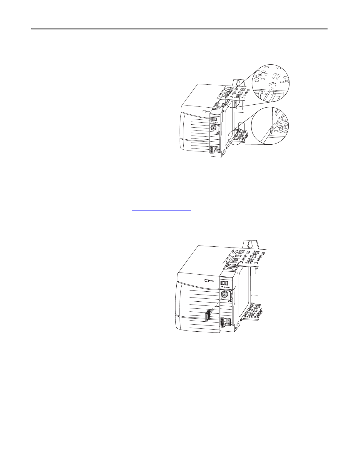
Parts Included with the 1756-L7x Controller
These parts are included with the controller:
• 1756-ESMCAP capacitor-based energy storage module (ESM)
• 1784-SD1 Secure Digital (SD) card, 1 GB
• 1747-KY controller key
Figure 1 - Parts with the 1756-L7x Controller
Rockwell Automation Publication 1756-UM001O-EN-P - October 2014 21
Page 22
Chapter 1 Install the 1756-L7x Controller
IMPORTANT
The 1756-L7x controllers ship with an SD card installed. We recommend that
you leave the SD card installed.
Parts Available for Use with the 1756-L7x Controller
You can choose to use the parts included with the controller and these parts
specific to your application.
.
If your application requires Then use this part
USB connection from a computer to the controller USB c able
Nonvolatile memory 1784-SD1 (1 GB) or 1784-SD2 (2 GB)
ESM without WallClockTime back-up power 1756-ESMNSE
ESM that secures the controller by blocking the USB
connection and SD card use
This ESM provides your application an enhanced degree of
security.
(2)
(1)
This ESM does not have WallClockTime back-up power.
Use this ESM if your application requires that the installed
ESM deplete its residual stored energy to 40 μJoule or less
before transporting it into or out of your application.
Additionally, you can use this ESM with only a 1756-L73
(8 MB) or smaller memory-sized controller.
1756-ESMNRM
(2)
1756-L7x Controller Installation
(1) The USB port is intended only for temporary loc al programming purposes and not intended for permanent connection. The USB
cable is not to exceed 3.0 m (9.84 ft) and must not contain hubs.
(2) For information about the hold-up time of the ESMs, see Hold-up Time (in days) on page 72 and stored energy depletion rate on
page 29
.
WARNING: Do not use the USB port in hazardous locations.
ATT EN TI ON :
• The USB port is intended only for temporary local programming purposes and
not intended for permanent connection.
• The USB cable is not to exceed 3.0 m (9.84 ft) and must not contain hubs.
These sections explain how to install the 1756-L7x controller. To install the
1756-L7x controller, complete the tasks summarized in this table.
Tas k Pag e
Insert the Controller into the Chassis 23
Insert the Key 24
Remove the SD Card 26
Install the SD Card 25
Install the ESM 28
22 Rockwell Automation Publication 1756-UM001O-EN-P - October 2014
Page 23
Install the 1756-L7x Controller Chapter 1
IMPORTANT
Insert the Controller into the Chassis
When installing a ControlLogix controller, you can do the following:
• Place the controller in any slot.
• Use multiple controllers in the same chassis.
You can install or remove a ControlLogix controller while chassis power is on and
the system is operating.
WARNING: When you insert or remove the module while backplane power
is on, an electrical arc can occur. This could cause an explosion in hazardous
location installations.
Be sure that power is removed or the area is nonhazardous before proceeding.
Repeated electrical arcing causes excessive wear to contacts on both the
controller and its mating connector on the chassis. Worn contacts may create
electrical resistance that can affect controller operation.
ATTENTION: Prevent Electrostatic Discharge
This equipment is sensitive to electrostatic discharge, which can cause internal
damage and affect normal operation. Follow these guidelines when you handle
this equipment:
• Touch a grounded object to discharge potential static.
• Wear an approved grounding wriststrap.
• Do not touch connectors or pins on component boards.
• Do not touch circuit components inside the equipment.
• Use a static-safe workstation, if available.
• Store the equipment in appropriate static-safe packaging when not in use.
The ESM begins charging when one of these actions occurs:
• The controller and ESM are installed into a powered chassis.
• Power is applied to the chassis that contains a controller with the ESM
installed.
• An ESM is installed into a powered controller.
After power is applied, the ESM charges for up to two minutes as indicated by
CHRG or ESM Charging on the status display.
Rockwell Automation Publication 1756-UM001O-EN-P - October 2014 23
Page 24
Chapter 1 Install the 1756-L7x Controller
Logix 55xx
RU
N
FO
RCE
S
D
OK
Top Circuit Board
Aligned
Bottom Circuit Board
Aligned
Logix 55xx
RUN
FORCE
SD
OK
1. Align the circuit board with the top and bottom guides in the chassis.
2. Slide the module into the chassis until it snaps into place.
3. Verify that the controller is flush with the power supply or other installed
modules.
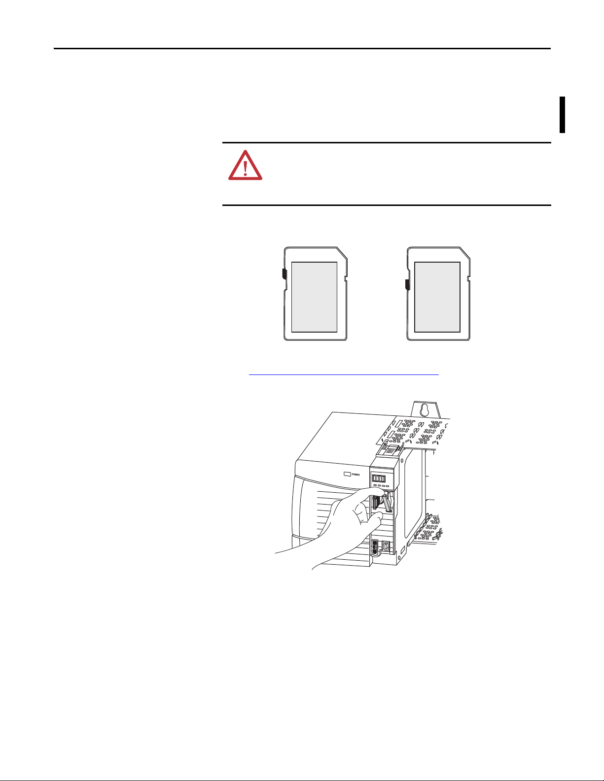
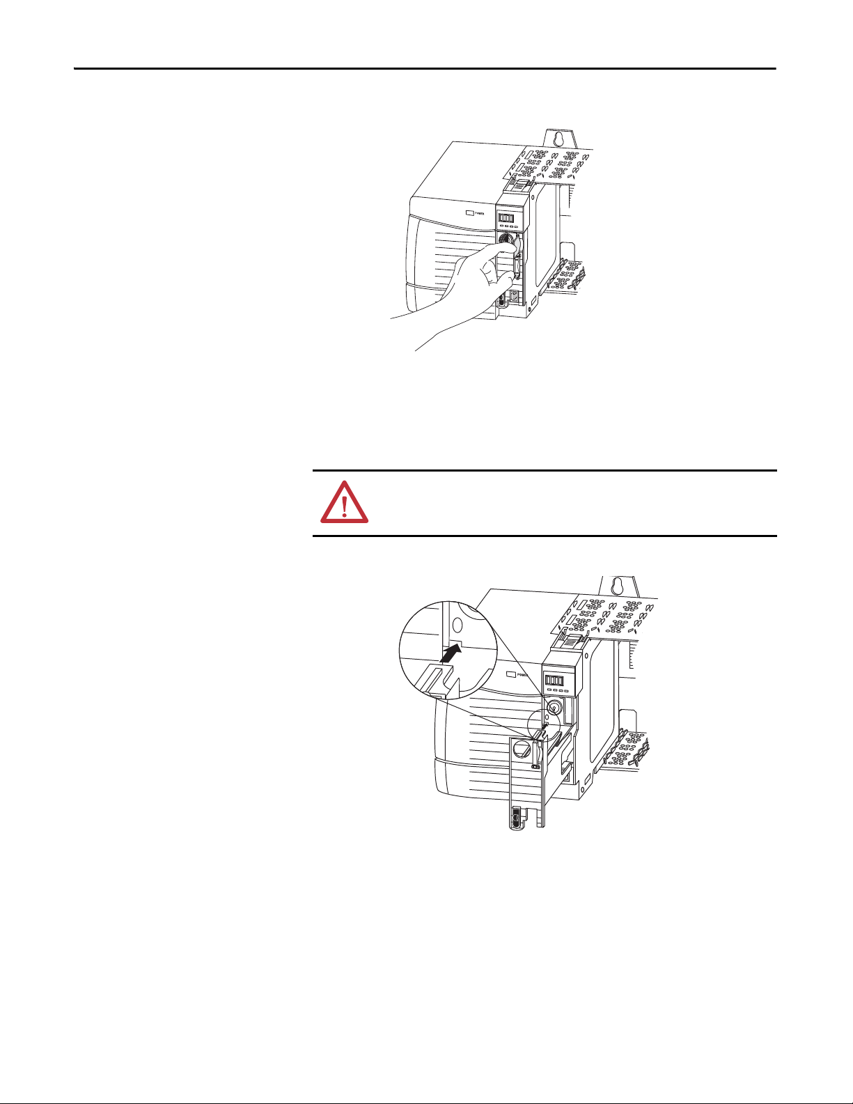
Insert the Key
After you have inserted the controller into the chassis, reference the Troubleshoot
the Module on page 183 for information to interpret the status indicators.
After the controller is installed, insert the key.
24 Rockwell Automation Publication 1756-UM001O-EN-P - October 2014
Page 25
Install the 1756-L7x Controller Chapter 1
Unlocked
Locked
Log
ix 55
xx
RUN
FORCE
SD
OK
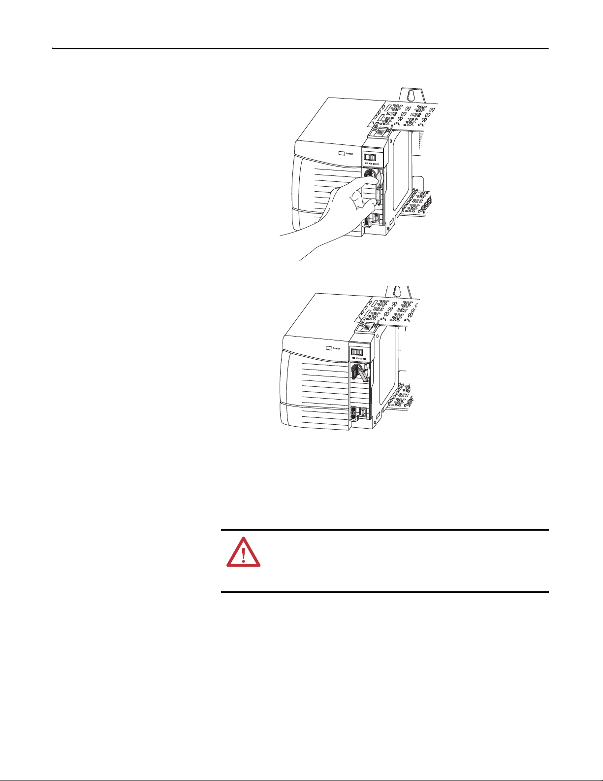
Install the SD Card
Complete these steps to install the SD card in the 1756-L7x controllers.
It is recommended that you leave the SD card in the controller, even when it is
not used. If the controller experiences a Major nonrecoverable Fault, extended
fault information is saved to the card.
WARNING: When you insert or remove the Secure Digital (SD) memory
card while power is on, an electrical arc can occur. This could cause an
explosion in hazardous location installations.
Be sure that power is removed or the area is nonhazardous before proceeding.
1. Verify that the SD card is locked or unlocked according to your preference.
For more information about the lock/unlock memory settings, see the
Load or Store to the Memory Card
on page 65.
2. Open the door for the SD card.
3. Insert the SD card into the SD card slot.
Rockwell Automation Publication 1756-UM001O-EN-P - October 2014 25
Page 26
Chapter 1 Install the 1756-L7x Controller
Log
ix 55
xx
RUN
FORCE
SD
OK
Log
ix 55
xx
RUN
FORCE
SD
OK
4. Gently press the card until it clicks into place.
5. Close the SD card door.
Remove the SD Card
The 1756-L7x controller ships with an SD card installed. Complete these steps to
remove the SD card from the 1756-L7x controller.
WARNING: When you insert or remove the Secure Digital (SD) memory
card while power is on, an electrical arc can occur. This could cause an
explosion in hazardous location installations.
Be sure that power is removed or the area is nonhazardous before proceeding.
26 Rockwell Automation Publication 1756-UM001O-EN-P - October 2014
Page 27
Install the 1756-L7x Controller Chapter 1
IMPORTANT
TIP
Log
ix 55
xx
RUN
FORCE
SD
OK
• Verify that the SD card status indicator is off and that the card is not in use
before removing it.
• We recommend that you do the following:
–Leave an SD card installed.
– Use the SD cards available from Rockwell Automation (catalog number
1784-SD1 or 1784-SD2).
• While other SD cards can be used with the controller, Rockwell Automation
has not tested the use of those cards with the controller. If you use an SD
card other than those cards that are available from Rockwell Automation,
you can experience data corruption or loss.
• Also, SD cards that are not provided by Rockwell Automation do not have
the same industrial, environmental, and certification ratings as those cards
that are available from Rockwell Automation.
1. Verify that the SD card is not in use by checking to be sure that the
SD indicator is Off.
You can also put the controller into Hard Run mode to keep the
controller from writing to the SD card while it is removed.
2. Open the door to access the SD card.
3. Press and release the SD card to eject it.
Rockwell Automation Publication 1756-UM001O-EN-P - October 2014 27
Page 28
Chapter 1 Install the 1756-L7x Controller
Logix 55xx
RUN
FO
RCE
SD
O
K
Log
ix 55
xx
RUN
FO
RC
E
SD
OK
4. Remove the SD card and close the door.
Install the ESM
To install an ESM in the 1756-L7x controller, complete these steps.
ATT EN TI ON : To avoid potential damage to the product when inserting the
ESM, align it in the track and slide forward with minimal force until the ESM
snaps into place.
1. Align the tongue-and-groove slots of the ESM and controller.
2. Slide the ESM back until it snaps into place.
The ESM begins charging after installation. The following status messages
indicate charging status:
• ESM Charging
• CHRG
After you install the ESM, it can take up to 15 seconds for the charging
status messages to display.
28 Rockwell Automation Publication 1756-UM001O-EN-P - October 2014
Page 29
Install the 1756-L7x Controller Chapter 1
IMPORTANT
TIP
IMPORTANT
.
Allow the ESM to finish charging before removing power from the controller.
Failure to do so can result in the loss of the application program. A type 1,
code 40 major fault is logged on powerup.
To verify that the ESM is fully charged, check the status display to confirm that
messages CHRG or ESM charging are no longer indicated.
We recommend that you check the WallClockTime object attributes after
installing an ESM to verify that time of the controller is correct.
The ESM contains a real-time clock. If the ESM is new or came from another
controller, the WallClockTime object attributes for your controller can change.
Uninstall the ESM
WARNING: If your application requires the ESM to deplete its residual stored
energy to 40 μJoule or less before you transport it into or out of the application,
use only the 1756-(SP)ESMNSE(XT) module. In this case, complete these steps
before you remove the ESM.
• Turn power off to the chassis.
After you turn power off to the chassis, the controller’s OK status indicator
transitions from green to solid red to OFF.
• Wai t at least 20 minutes for the residual stored energy to decrease to
40 μJoule or less before you remove the ESM.
There is no visual indication of when the 20 minutes has expired. You must trac k
that time period.
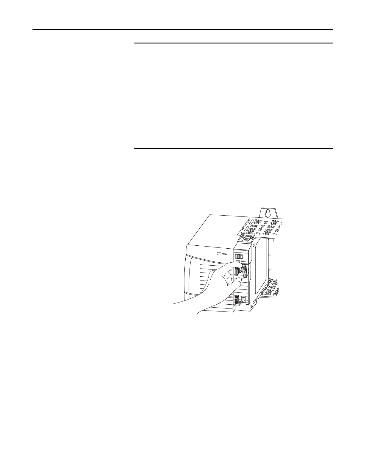
WARNING: When you insert or remove the energy storage module while
backplane power is on, an electrical arc can occur. This could cause an explosion
in hazardous location installations.
Be sure that power is removed or the area is nonhazardous before proceeding.
Repeated electrical arcing causes excessive wear to contacts on both the module
and its mating connector.
Before you remove an ESM, make necessary adjustments to your program
to account for potential changes to the WallClockTime attribute.
Consider these points before removing the ESM:
• The following ESM modules can be currently installed in your 1756-L7x
or 1756-L7xXT controller:
– 1756-ESMCAP
– 1756-ESMNSE
– 1756-ESMCAPXT
– 1756-ESMNSEXT
Rockwell Automation Publication 1756-UM001O-EN-P - October 2014 29
Page 30

Chapter 1 Install the 1756-L7x Controller
IMPORTANT
• The 1756-L7x controllers come with the 1756-ESMCAP module
installed. The 1756-L7xXT extreme temperature controller ships with a
1756-ESMCAPXT module installed. For more information on how to
use a 1756-ESMNSE, 1756-ESMNRM, 1756-ESMNSEXT, or
1756-ESMNRMXT module, see page 28
.
• After the 1756-L7x or 1756-L7xXT controllers lose power, because the
chassis power is turned off or the controller has been removed from a
powered chassis, do not immediately remove the ESM.
Wait until the OK status indicator on the controller transitions from
Green to Solid Red to OFF before you remove the ESM.
• You can use the 1756-ESMNSE module with only a 1756-L73 (8 MB) or
smaller memory-sized controller.
• Use the 1756-ESMNSE module if your application requires that the
installed ESM deplete its residual stored energy to 40 μJoule or less before
transporting it into or out of your application.
• Once it is installed, you cannot remove the 1756-ESMNRM or
1756-ESMNRMXT module from a 1756-L7x or 1756-L7xXT controller.
Complete these steps to remove an ESM module from the controller.
1. Remove the key from the mode switch.
The next step depends on which of the following conditions applies to your
application.
• If you are removing the ESM from a powered 1756-L7x controller, go to
step 2
.
• If you are removing the ESM from a 1756-L7x controller that is not
powered, because the chassis power is turned off or the controller has
been removed from a powered chassis, do not immediately remove
the ESM.
Wait until the OK status indicator on the controller transitions from Green to
Solid Red to OFF before you remove the ESM.
After the OK status indicator transitions to Off, go to step 2
.
30 Rockwell Automation Publication 1756-UM001O-EN-P - October 2014
Page 31

Install the 1756-L7x Controller Chapter 1
Logix 55xx
RUN
FO
RCE
SD
OK
Log
ix 55
xx
RUN
FORCE
SD
OK
2. Use your thumb to press down on the black release and pull the ESM away
from the controller.
Rockwell Automation Publication 1756-UM001O-EN-P - October 2014 31
Page 32

Chapter 1 Install the 1756-L7x Controller
Notes:
32 Rockwell Automation Publication 1756-UM001O-EN-P - October 2014
Page 33

Install the 1756-L6x Controller
Top ic Pag e
Before You Begin 35
1756-L6x Controller Parts 35
1756-L6x Controller Installation 36
CompactFlash Card Installation and Removal 36
Battery Connection and Replacement 39
Insert the Controller into the Chassis 42
Remove the Controller from the Chassis 44
Chapter 2
ATTENTION: Environment and Enclosure
This equipment is intended for use in a Pollution Degree 2 industrial environment, in overvoltage Category II applications (as
defined in IEC 60664-1), at altitudes up to 2000 m (6562 ft) without derating.
This equipment is not intended for use in residential environments and may not provide adequate protection to radio
communication services in such environments.
This equipment is supplied as open-type equipment. It must be mounted within an enclosure that is suitably designed for those
specific environmental conditions that will be present and appropriately designed to prevent personal injury resulting from
accessibility to live parts. The enclosure must have suitable flame-retardant properties to prevent or minimize the spread of
flame, complying with a flame spread rating of 5VA or be approved for the application if nonmetallic. The interior of the
enclosure must be accessible only by the use of a tool. Subsequent sections of this publication may contain additional
information regarding specific enclosure type ratings that are required to comply with certain product safety certifications.
In addition to this publication, see the following:
• Industrial Automation Wiring and Grounding Guidelines, publication 1770-4.1
, for additional installation requirements.
• NEMA 250 and IEC 60529, as applicable, for explanations of the degrees of protection provided by enclosures.
Rockwell Automation Publication 1756-UM001O-EN-P - October 2014 33
Page 34

Chapter 2 Install the 1756-L6x Controller
North American Hazardous Location Approval
The following information applies when operating this equipment in
hazardous locations.
Products marked "CL I, DIV 2, GP A, B, C, D" are suitable for use in Class I Division 2 Groups
A, B, C, D, Hazardous Locations and nonhazardous locations only. Each product is supplied
with markings on the rating nameplate indicating the hazardous location temperature
code. When combining products within a system, the most adverse temperature code
(lowest "T" number) may be used to help determine the overall temperature code of the
system. Combinations of equipment in your system are subject to investigation by the
local Authority Having Jurisdiction at the time of installation.
Informations sur l’utilisation de cet équipement en environnements
dangereux.
Les produits marqués "CL I, DIV 2, GP A, B, C, D" ne conviennent qu'à une utilisation en
environnements de Classe I Division 2 Groupes A, B, C, D dangereux et non dangereux.
Chaque produit est livré avec des marquages sur sa plaque d'identification qui indiquent
le code de température pour les environnements dangereux. Lorsque plusieurs produits
sont combinés dans un système, le code de température le plus défavorable (code de
température le plus faible) peut être utilisé pour déterminer le code de température
global du système. Les combinaisons d'équipements dans le système sont sujettes à
inspection par les autorités locales qualifiées au moment de l'installation.
WARNING: EXPLOSION HAZARD
• Do not disconnect equipment unless power has
been removed or the area is known to be
nonhazardous.
• Do not disconnect connections to this
equipment unless power has been removed or
the area is known to be nonhazardous. Secure
any external connections that mate to this
equipment by using screws, sliding latches,
threaded connectors, or other means provided
with this product.
• Substitution of components may impair
suitability for Class I, Division 2.
• If this product contains batteries, they must only
be changed in an area known to be
WARNING: RISQUE D’EXPLOSION
• Couper le courant ou s'assurer que
l'environnement est classé non dangereux avant
de débrancher l'équipement.
• Couper le courant ou s'assurer que
l'environnement est classé non dangereux avant
de débrancher les connecteurs. Fixer tous les
connecteurs externes reliés à cet équipement à
l'aide de vis, loquets coulissants, connecteurs
filetés ou autres moyens fournis avec ce produit.
• La substitution de composants peut rendre cet
équipement inadapté à une utilisation en
environnement de Classe I, Division 2.
• S'assurer que l'environnement est classé non
dangereux avant de changer les piles.
nonhazardous.
European Hazardous Location Approval
The following applies when the product bears the Ex Marking.
This equipment is intended for use in potentially explosive atmospheres as defined by European Union Directive 94/9/EC and has been found to comply with the Essential Health and
Safety Requirements relating to the design and construction of Category 3 equipment intended for use in Zone 2 potentially explosive atmospheres, given in Annex II to this Directive.
Compliance with the Essential Health and Safety Requirements has been assured by compliance with EN 60079-15 and EN 60079-0.
ATTENTION: This equipment is not resistant to sunlight or other sources of UV radiation.
WARNING:
• This equipment shall be mounted in an ATEX certified enclosure with a minimum ingress protection rating of at least IP54
(as defined in IEC60529) and used in an environment of not more than Pollution Degree 2 (as defined in IEC 60664-1) when
applied in Zone 2 environments. The enclosure must utilize a tool removable cover or door.
• This equipment shall be used within its specified ratings defined by Rockwell Automation.
• This equipment must be used only with ATEX certified Rockwell Automation backplanes.
• Secure any external connections that mate to this equipment by using screws, sliding latches, threaded connectors, or other
means provided with this product.
• Do not disconnect equipment unless power has been removed or the area is known to be nonhazardous.
34 Rockwell Automation Publication 1756-UM001O-EN-P - October 2014
Page 35

Install the 1756-L6x Controller Chapter 2
1756-L6x Controll er
1747-KY Key
1756-BA1 or 1756-BA2
ATTENTION: Personnel responsible for the application of safety-related programmable electronic systems (PES) shall be
aware of the safety requirements in the application of the system and shall be trained in using the system.
Before You Begin
1756-L6x Controller Parts
See 1756-IN005 to install a ControlLogix chassis and power supply before you
install your controller and power supply.
These sections describe parts that are included with the 1756-L6x controllers and
available accessory parts:
• One of the following batteries is included with your controller:
– For series A controllers, catalog number 1756-BA1
– For series B controllers, catalog number 1756-BA2
• Key, catalog number 1747-KY
Figure 2 - Parts Included with the 1756-L6x Controller
Logix 5563
RUN
I/O
FO
RCE
RS232
BAT
O
K
RU
N
REM
PROG
Parts Not Included with the 1756-L6x Controller
You can choose to use the parts included with the controller and these parts
specific to your application.
If your application requires Then use this component
RS-232 connection to the controller 1756-CP3 serial cable
Nonvolatile memory 1784-CF128 CompactFlash card
Expanded battery life for extended memory retention 1756-BATM battery module
(1) The 1756-BATM can be used with series A controllers, but it cannot be used with series B controllers. Series B controllers
use battery power differently than previous controllers and therefore battery considerations for this series controller
vary. For more information to determine what battery to use, see the ControlLogix Controllers Selection Guide,
publication 1756-SG001
.
Rockwell Automation Publication 1756-UM001O-EN-P - October 2014 35
(1)
Page 36

Chapter 2 Install the 1756-L6x Controller
1
2
3
4
1756-L6x Controller Installation
CompactFlash Card Installation and Removal
These sections explain how to install a 1756-L6x controller. To install the
1756-L6x controller, complete the tasks summarized in this table.
Tas k Pag e
CompactFlash Card Installation and Removal 36
Battery Connection and Replacement 39
Insert the Controller into the Chassis 42
Remove the Controller from the Chassis 44
The installation and removal of a CompactFlash card depends on the controller.
WARNING: When you insert or remove the CompactFlash Card while power
is on, an electrical arc can occur. This could cause an explosion in hazardous
location installations.
Be sure that power is removed or the area is nonhazardous before proceeding.
• If you are using a series A controller, reference these sections:
– Install a CompactFlash Card in a Series A Controller
– Remove a CompactFlash Card from a Series A Controller
on page 36.
on page 37.
• If you are using a series B controller, reference these sections:
– Install a CompactFlash Card in a Series B Controller
– Remove a CompactFlash Card from a Series B Controller
on page 37.
on page 38.
Install a CompactFlash Card in a Series A Controller
Complete these steps to install a CompactFlash card in a series A controller.
.
1. Lay the controller on its side with the front facing to the left.
2. Raise the locking clip.
3. Insert the CompactFlash card into the slot at the bottom of the controller.
4. Pull the clip forward and downward until it snaps into place over the card.
36 Rockwell Automation Publication 1756-UM001O-EN-P - October 2014
Page 37

Install the 1756-L6x Controller Chapter 2
1
2
3
1
2
3
4
Remove a CompactFlash Card from a Series A Controller
Complete these steps to remove a CompactFlash card from a series A controller.
1. Lay the controller in its side with the mode switch facing left.
2. Raise the locking clip.
3. Gently pull the card out of the slot.
Install a CompactFlash Card in a Series B Controller
Complete these steps to install a CompactFlash card in a series B controller.
1. Open the door of the controller and push the CompactFlash latch to the
left.
Rockwell Automation Publication 1756-UM001O-EN-P - October 2014 37
Page 38

Chapter 2 Install the 1756-L6x Controller
1
2
3
2. Insert the CompactFlash card with the Allen-Bradley® logo pointing left.
3. Release the latch and secure it over the CompactFlash card.
Remove a CompactFlash Card from a Series B Controller
Complete these steps to remove a CompactFlash card from a series B controller.
1. Verify that the OK indicator is solid green and open the door of the
controller.
2. Push and hold the CompactFlash latch to the left.
3. Push the eject button and remove the card.
4. Release the latch.
38 Rockwell Automation Publication 1756-UM001O-EN-P - October 2014
Page 39

Install the 1756-L6x Controller Chapter 2
If the temperature 2.54 cm (1 in.) below the chassis is Replace the battery within
-25…35 °C (-13…95 °F) No replacement required
36…40 °C (96.8…104 °F) 3 years
41…45 °C (105.8…113 °F) 2 years
46…50 °C (114.8…122 °F) 16 months
51…55 °C (123.8…131 °F) 11 months
56…70 °C (132.8…158 °F) 8 months
Battery Connection and Replacement
This product contains a hermetically-sealed lithium battery that may need to be
replaced during the life of the product.
At the end of its life, the battery contained in this product should be collected
separately from any unsorted municipal waste.
The collection and recycling of batteries helps protect the environment and
contributes to the conservation of natural resources as valuable materials are
recovered.
WARNING: When you connect or disconnect the battery an electrical arc can
occur. This could cause an explosion in hazardous location installations. Be sure
that power is removed or the area is nonhazardous before proceeding.
For safety information on the handling of lithium batteries, including handling
and disposal of leaking batteries, see Guidelines for Handling Lithium Batteries,
publication AG-5.4
.
IMPORTANT: To prevent program loss, replace a 1756-BA1 or 1756-BA2 battery
according to the following schedule even if the BAT status indicator is Off.
Connection of the battery varies depending on your controller series:
• If you are using a series A controller, see page 39
• If you are using a series B controller, see page 40
Install the Battery on a Series A Controller
Complete these steps to install a 1756-BA1 battery on a series A controller.
Rockwell Automation Publication 1756-UM001O-EN-P - October 2014 39
ATT EN TI ON : Store batteries in a cool, dry environment. We recommend
°C (77 °F) with 40…60% relative humidity. You can store batteries for up to
25
30 days between -45…85
avoid leakage or other hazards, do not store batteries above 60
°C (-49…185 °F), such as during transportation. To
°C (140 °F) for
more than 30 days.
.
.
Page 40

Chapter 2 Install the 1756-L6x Controller
DATE
For information to install a 1756-BATM battery module or replace a 1756BATM assembly, see the ControlLogix Battery Module Installation Instructions,
publication 1756-IN576
.
ATTENTION: For a series A controller, connect only a 1756-BA1 battery or a
1756-BATM battery module. The use of other batteries can damage the
controller.
Wire Terminal Location Connected Wire
Top No connection
Middle Black lead (-)
Bottom Red lead (+)
1. Connect the battery connector to the port to the right of the battery slot.
2. Snap the battery into the battery slot.
3. Write the date on the battery label.
4. Attach the label to the inside of the controller door.
Install the Battery on a Series B Controller
Complete these steps to install the battery on a series B controller.
AT TE NT IO N: For a series B controller, connect only a 1756-BA2 battery. The
use of other batteries can damage the controller.
40 Rockwell Automation Publication 1756-UM001O-EN-P - October 2014
Page 41

Install the 1756-L6x Controller Chapter 2
DATE
1. Plug the battery connector into the battery port (+ Red, - Black).
2. Insert the battery, with the arrow pointing up, into the battery slot.
3. Write the date on the battery label.
4. Attach the label to the inside of the controller door.
Rockwell Automation Publication 1756-UM001O-EN-P - October 2014 41
Page 42

Chapter 2 Install the 1756-L6x Controller
Insert the Controller into the Chassis
When installing a ControlLogix controller, you can do the following:
• Place the controller in any slot.
• Use multiple controllers in the same chassis.
You can install a ControlLogix controller while chassis power is on and the
system is operating.
WARNING: When you insert or remove the module while backplane power is
on, an electrical arc can occur. This could cause an explosion in hazardous
location installations. Be sure that power is removed or the area is nonhazardous
before proceeding.
Repeated electrical arcing causes excessive wear to contacts on both the controller
and its mating connector on the chassis. Worn contacts may create electrical
resistance that can affect controller operation.
ATTENTION: Prevent Electrostatic Discharge
This equipment is sensitive to electrostatic discharge, which can cause internal
damage and affect normal operation. Follow these guidelines when you handle
this equipment:
• Touch a grounded object to discharge potential static.
• Wear an approved grounding wriststrap.
• Do not touch connectors or pins on component boards.
• Do not touch circuit components inside the equipment.
• Use a static-safe workstation, if available.
• Store the equipment in appropriate static-safe packaging when not in use.
ATT EN TI ON : If this equipment is used in a manner not specified by the
manufacturer, the protection provided by the equipment can be impaired.
Complete these steps to insert the controller into the chassis.
1. Insert the key into the controller.
2. Turn the key to the PROG position.
3. Align the circuit board with the top and bottom guides in the chassis.
4. Slide the module into the chassis.
42 Rockwell Automation Publication 1756-UM001O-EN-P - October 2014
Page 43

Install the 1756-L6x Controller Chapter 2
5. Verify that the controller is flush with the power supply or other installed
modules.
6. Verify that the top and bottom latches are engaged.
After you have inserted the controller into the chassis, you can reference the
Troubleshoot the Module
on page 183 for more information that is related to the
state of the controller.
Rockwell Automation Publication 1756-UM001O-EN-P - October 2014 43
Page 44

Chapter 2 Install the 1756-L6x Controller
1
2
1
Remove the Controller from the Chassis
You can remove a controller while chassis power is on and the system is operating.
The devices that are owned by the controller go to their configured fault state if
you remove the controller.
WARNING: When you insert or remove the module while backplane power is
on, an electrical arc can occur. This could cause an explosion in hazardous
location installations. Be sure that power is removed or the area is
nonhazardous before proceeding.
Repeated electrical arcing causes excessive wear to contacts on both the controller
and its mating connector in the chassis. Worn contacts may create electrical
resistance that can affect controller operation.
Complete these steps to remove the controller from the chassis.
1. Press the locking tabs on the top and bottom of the controller.
2. Slide the controller out of the chassis.
44 Rockwell Automation Publication 1756-UM001O-EN-P - October 2014
Page 45

Start Using the Controller
Top ic Pag e
Make Connections 45
Connect to the 1756-L7x Controller 46
Connect to the 1756-L6x Controller 49
Upgrade Controller Firmware 52
Set the Communication Path 58
Go Online with the Controller 58
Download to the Controller 59
Upload from the Controller 60
Choose the Controller Operation Mode 62
Use the Mode Switch to Change the Operation Mode 62
Use Logix Designer to Change the Operation Mode 64
Load or Store to the Memory Card 65
Use ControlLogix Energy Storage Modules (ESMs) 70
Estimate the ESM Support of the WallClockTime 72
Maintain the Battery (Only 1756-L6x Controllers) 72
Chapter 3
Make Connections
Before you can begin using your controller, you must make a connection to the
controller.
1756-L7x Connection Options
Connection options with the 1756-L7x include the following:
• Connect by using a USB cable as described in Connect to the
1756-L7x Controller on page 46.
• Install and configure a communication module in the chassis with the
controller as described in the installation instructions for the
communication module.
For information on Double Data Rate (DDR) backplane communication usage,
see Double Data Rate (DDR) Backplane Communication
Rockwell Automation Publication 1756-UM001O-EN-P - October 2014 45
on page 88.
Page 46

Chapter 3 Start Using the Controller
TIP
1756-L6x Connection Options
Connection options with the 1756-L6x include the following:
• Connect by using a serial cable as described in Connect to the
1756-L6x Controller on page 49.
• Install and configure a communication module in the chassis with the
controller as described in the installation instructions for the
communication module.
When upgrading your 1756-L6x controller firmware, we recommend you use a
network connection other than the serial cable. Serial connections are much
slower than other communication connections.
Connect to the 1756-L7x Controller
The controller has a USB port that uses a Type B receptacle. The port is USB 2.0
compatible and runs at 12 Mbps.
To use the USB port of the controller, you must have RSLinx software,
version 2.56 or later, installed on your workstation. Use a USB cable to connect
your workstation to the USB port. With this connection, you can upgrade
firmware and download programs to the controller directly from your
workstation.
ATTENTION: The USB port is intended only for temporary local
programming purposes and not intended for permanent connection. The
USB cable is not to exceed 3.0 m (9.84 ft) and must not contain hubs.
WARNING: Do not use the USB port in hazardous locations.
46 Rockwell Automation Publication 1756-UM001O-EN-P - October 2014
Page 47

Figure 3 - USB Connection
TIP
Log
ix 55
xx
RUN
FORCE
SD
OK
32007-M
Configure the USB Driver
Start Using the Controller Chapter 3
To configure RSLinx software to use a USB port, you must first configure a USB
driver.
To configure a USB driver, perform this procedure.
1. Connect your controller and workstation by using a USB cable.
The Found New Hardware Wizard dialog box appears.
2. Click any of the Windows Update connection options and click Next.
If the software for the USB driver is not found and the installation is
canceled, verify that you have installed RSLinx Classic software,
version 2.57 or later.
Rockwell Automation Publication 1756-UM001O-EN-P - October 2014 47
Page 48

Chapter 3 Start Using the Controller
Virtual Chassis Driver
USB Port Driver
3. Click Install the software automatically (Recommended) and click Next.
The software is installed.
4. Click Finish to configure your USB driver.
To browse to your controller in RSLinx software, click the RSWho icon.
The RSLinx Workstation organizer appears.
Your controller appears under two drivers, a virtual chassis and the USB port. You
can use either driver to browse to your controller.
48 Rockwell Automation Publication 1756-UM001O-EN-P - October 2014
Page 49

Start Using the Controller Chapter 3
To W ork st ati on
To C ont ro lle r
To Workstation To Controller
Connect to the 1756-L6x Controller
The 1756-L6x ControlLogix controller uses a serial port for workstation
connections.
WARNING: If you connect or disconnect the serial cable with power applied to
this module or the serial device on the other end of the cable, an electrical arc
can occur. This could cause an explosion in hazardous location installations.
Be sure that power is removed or the area is nonhazardous before proceeding.
To connect a workstation to the serial port, you can make your own serial cable or
use one of these cables:
• 1756-CP3 serial cable
• 1747-CP3 cable from the SLC™ product family (if you use this cable, it can
be difficult to close the controller door)
Follow these guidelines if you make your own serial cable:
• Limit the length to 15.2 m (50 ft).
• Wire the connectors as shown.
• Attach the shield to the connectors.
1 CD
2 RDX
3 TXD
4 DTR
COMMON
6 DSR
7 RTS
8 CTS
9
1 CD
2 RDX
3 TXD
4 DTR
COMMON
6 DSR
7 RTS
8 CTS
9
Plug the controller end of the serial cable into the RS-232 port on the front of the
controller.
Rockwell Automation Publication 1756-UM001O-EN-P - October 2014 49
Page 50

Chapter 3 Start Using the Controller
Configure the Serial Driver
Use RSLinx software to configure the RS-232 DF1 device driver for serial
communication.
To configure the driver, perform this procedure.
1. In RSLinx software, from the Communications menu, choose Configure
Drivers.
50 Rockwell Automation Publication 1756-UM001O-EN-P - October 2014
Page 51

Start Using the Controller Chapter 3
2. From the Available Driver Types pull-down menu, choose the
RS-232 DF1 device driver.
3. Click Add New.
The Add New RSLinx Driver dialog box appears.
4. Type the driver name and click OK.
5. Specify the serial port settings.
a. From the Comm Port pull-down menu, choose the serial port on the
workstation to which the cable is connected.
b. From the Device pull-down menu, choose Logix 5550/CompactLogix.
c. Click Auto-Configure.
6. If the auto configuration is successful, click OK.
Rockwell Automation Publication 1756-UM001O-EN-P - October 2014 51
Page 52

Chapter 3 Start Using the Controller
IMPORTANT
If the auto configuration is not successful, verify that the correct Comm
Port was selected.
7. Click Close.
Upgrade Controller Firmware
You can choose to upgrade controller firmware by using one of these tools:
• ControlFLASH™ software that is packaged with the Studio 5000
environment
• AutoFlash feature of the Logix Designer application
To upgrade your controller firmware, complete the tasks that are listed in this
table.
Task Pag e
Determine Required Controller Firmware 52
Obtain Controller Firmware 53
Use Control FLASH Software to Upgrade Firmware 53
Use AutoFlash to U pgrade Firmware 56
Determine Required Controller Firmware
The controller must be in Remote Program or Program mode and all major
recoverable faults must be cleared to accept upgrades.
Use Ta b l e 4 to determine what firmware revision is required for your controller.
Table 4 - Firmware Required for Controllers
Controller Series Use this firmware revision
1756-L61 A 12.x or later
B 13.40 or later
1756-L62 A 12.x or later
B 13.40 or later
1756-L63 A • If not using a CompactFlash card, 10.x or later
B 13.40 or later
1756-L63XT B 13.40 or later
1756-L64 B 16 or later
1756-L65 B 17 or later
1756-L71 A 20 or later
1756-L72 A 19 or later
1756-L73 A 19 or later
1756-L73XT A 19 or later
1756-L74 A 19 or later
• If using a CompactFlash card, 11.x or later
52 Rockwell Automation Publication 1756-UM001O-EN-P - October 2014
Page 53

Start Using the Controller Chapter 3
IMPORTANT
1756-L6x Controllers
1756-L7x Controll ers
Table 4 - Firmware Required for Controllers (Continued)
Controller Series Use this firmware revision
1756-L75 A 19 or later
Obtain Controller Firmware
Controller firmware is packaged with the Studio 5000 environment. In addition,
controller firmware is also available for download from the Rockwell Automation
Technical Support website at http://www.rockwellautomation.com/support/
.
Use ControlFLASH Software to Upgrade Firmware
To upgrade your controller firmware with ControlFLASH software, complete
these steps.
If the SD card is locked and the Load Image option of the store project is set to
On Power Up, the controller firmware is not updated as a result of these steps.
The previously stored firmware and project are loaded instead.
1. Verify that the network connection is made and the network driver has
been configured in RSLinx software.
2. Start ControlFLASH software and click Next to begin the upgrade
process.
3. Select the catalog number of your controller and click Next.
4. Expand the network driver to locate your controller.
Rockwell Automation Publication 1756-UM001O-EN-P - October 2014 53
Page 54

Chapter 3 Start Using the Controller
1756-L7x Controller with USB Network Driver
1756-L6x Controller with Ethernet Network Driver
1756-L6x Controller Upgrade
1756-L7x Controller Upgrade
5. Select the controller and click Next.
6. Select the firmware revision that you want to upgrade to and click Next.
54 Rockwell Automation Publication 1756-UM001O-EN-P - October 2014
Page 55

Start Using the Controller Chapter 3
TIP
1756-L6x Controller Progress1756-L7x Controller Progress
TIP
If you are using a 1756-L7x controller and experience a Script File Error after selecting the firmware revision number (see the
following example), there is likely an anomaly with your firmware files.
To recover, perform the following:
• Go to http://www.rockwellautomation.com/support/
and download the firmware revision you are trying to upgrade.
Replace the firmware revision that you have previously installed with that posted on the Technical Support website.
• If the replacement firmware revision does not resolve the anomaly, contact Rockwell Automation Technical Support.
7. Click Finish.
8. When a confirmation dialog box appears, click Yes.
The progress dialog box indicates the progress of the firmware upgrade.
1756-L7x controllers indicate progress in updates and blocks. 1756-L6x
controllers indicate progress only in blocks.
WARNING: Allow the firmware update to fully complete before cycling power
or otherwise interrupting the upgrade.
If the ControlFLASH upgrade of the controller is interrupted, the 1756-L6x and
1756-L7x controllers revert to boot firmware, that is firmware revision 1.xxx.
When the upgrade is complete, the Update Status dialog box indicates that
the upgrade is complete.
Rockwell Automation Publication 1756-UM001O-EN-P - October 2014 55
Page 56

Chapter 3 Start Using the Controller
IMPORTANT
9. Click OK.
10. Close ControlFLASH software.
Use AutoFlash to Upgrade Firmware
To upgrade your controller firmware with the AutoFlash feature, complete these
steps.
If the SD card is locked and the Load Image option of the stored project is set to
On Power Up, the controller firmware is not updated as a result of these steps.
The previously stored firmware and project are loaded instead.
1. Verify that the network connection is made and your network driver is
configured in RSLinx software.
2. Use the Logix Designer application to create a controller project at the
version you need.
3. Click RSWho to specify the controller path.
56 Rockwell Automation Publication 1756-UM001O-EN-P - October 2014
Page 57

Start Using the Controller Chapter 3
1756-L6x Controller with Ethernet Driver
1756-L7x Controller with USB Driver
4. Select your controller and click Update Firmware.
5. Select the firmware revision to upgrade to and click update.
6. Click Yes.
The firmware upgrade begins.
Rockwell Automation Publication 1756-UM001O-EN-P - October 2014 57
Page 58

Chapter 3 Start Using the Controller
Allow the firmware upgrade to complete without interruption.
When the firmware upgrade is complete, the Who Active dialog box
opens.
Set the Communication Path
To go online with the controller, you must specify a communication path in the
Logix Designer application. You specify the communication path after you create
a controller program.
Complete these steps to specify the communication path after you have created
your program.
1. Click Who Active.
2. Expand the communication path and select the controller.
3. Click Set Project Path.
Go Online with the Controller
58 Rockwell Automation Publication 1756-UM001O-EN-P - October 2014
Use one of these methods to go online with the controller:
Page 59

Start Using the Controller Chapter 3
• After setting the communication path, click Go Online in the Who Active
dialog box.
• From the Controller Status menu, choose Go Online.
Download to the Controller
When you download a project to the controller, it moves the project from the
Logix Designer application onto the controller. You can download a project in
two ways:
• Use the Who Active Dialog Box to Download
• Use the Controller Status Menu to Download on page 60
on page 59
Use the Who Active Dialog Box to Download
You can use the features of the Who Active dialog box to download to your
controller after you have set the communication path. Complete these steps to
download to the controller.
1. After setting the communication path, click Download in the Who Active
dialog box.
2. Click Download after reading the warnings in the Download dialog box.
Rockwell Automation Publication 1756-UM001O-EN-P - October 2014 59
Page 60

Chapter 3 Start Using the Controller
TIP
Use the Controller Status Menu to Download
Upload from the Controller
After you set a communication path in the Logix Designer application, you can
use the Controller Status menu to download to the controller. To download,
from the Controller Status menu, choose Download.
Figure 4 - Download Via the Controller Status Menu
After the download completes on a 1756-L7x controller, the project name is
indicated on the scrolling status display.
When you upload a project to the controller, it copies the project from the
controller to the Logix Designer application. To upload a project, use one of these
methods:
• Use the Who Active Dialog Box to Upload
• Use the Controller Status Menu to Upload, page 61
, page 60
Use the Who Active Dialog Box to Upload
You can use the features of the Who Active dialog box to upload from your
controller after you have set the communication path. Complete these steps to
upload from the controller.
60 Rockwell Automation Publication 1756-UM001O-EN-P - October 2014
Page 61

Start Using the Controller Chapter 3
1. After setting the communication path, click Upload in the Who Active
dialog box.
2. Click Upload after verifying the project that you are uploading in the
Connected to Upload dialog box.
Use the Controller Status Menu to Upload
After you have set a communication path in the project, you can use the
Controller Status menu to upload from the controller. To upload, from the
Controller Status menu, choose Upload.
Rockwell Automation Publication 1756-UM001O-EN-P - October 2014 61
Page 62

Chapter 3 Start Using the Controller
Figure 5 - Upload Via the Controller Status Menu
Choose the Controller Operation Mode
Use Ta b l e 5 as a reference when determining your controller Operation mode.
Table 5 - Controller Operation Modes and Meanings
If you want to Select one of these modes
Run Remote Program
Run Test Program
Turn outputs to the state commanded by the
logic of the project
Turn outputs to their configured state for
Program mode
Execute (scan) tasks X X X
Change the mode of the controller via Logix
Designer application
Download a project X X X X
Schedule a ControlNet network X X
While online, edit the project X X X X
Send messages X X X
Send and receive data in response to a message
from another controller
Produce and consume tags X X X X X
XX
XX X
XXX
XXXX X
Use the Mode Switch to Change the Operation Mode
Use the mode switch to change the operation mode. The controller mode switch
provides a mechanical means to enhance controller and control system security.
You must physically move the mode switch on the controller to change its
operating mode from RUN, to REM, or to PROG. When the mode switch on
the controller is set to RUN mode, features like online editing, program
downloads, and firmware upgrades are prohibited. See Ta b l e 5
of prohibited features.
The physical mode switch can complement other authorization and
authentication methods that similarly control user-access to the controller, such
as the following:
• Logix CPU Security tool
• FactoryTalk Security service
62 Rockwell Automation Publication 1756-UM001O-EN-P - October 2014
for a complete list
Page 63

Start Using the Controller Chapter 3
IMPORTANT
1756-L7x 1756-L6x
Mode Switch
During runtime, we recommend that you place the controller mode switch in
RUN mode and remove the key (if applicable) from the switch. This can help
discourage unauthorized access to the controller or potential tampering with
the program of the controller, configuration, or device firmware. Place the
mode switch in REM or PROG mode during controller commissioning and
maintenance and whenever temporary access is necessary to change the
program, configuration, or firmware of the product.
The mode switch on the front of the controller can be used to change the
controller to one of these modes:
• Run (RUN)
• Remote (REM)
• Program (PROG)
Mode Switch
Position
RUN Run mode—The controller is actively controlling
Available Controller Modes
the process/machine. Projects cannot be edited in
the Logix Designer application when in Run mode.
ATTENTION:
Run mode is used only when all conditions are
safe.
Rockwell Automation Publication 1756-UM001O-EN-P - October 2014 63
Page 64

Chapter 3 Start Using the Controller
Mode Switch
Position
REM Remote Run mode—This mode is identical to
PROG Program mode—The controller mode during
Available Controller Modes
Run mode except you can edit the project online.
Remote Program mode—This mode is identical
to Program mode.
Remote Test mode—The controller mode during
which code is executing. I/O is not controlled, and
limited editing operations are available.
Output modules are commanded to their Program
mode state (on, off, or hold).
Note: The mode of the controller can be changed
from within the Logix Designer application.
which programming language is not executing. I/O
is not controlled, and limited editing operations are
available.
Output modules are commanded to their Program
mode state (On, Off, or Hold).
In this position, controller modes cannot be
changed through the Logix Designer application.
ATTENTION:
You are able to modify a project file online in
Remote Run mode.
Be sure to control outpu ts with care to avoid
injury to personnel and damage to equipment.
Outputs are commanded to their Program
mode state, which can cause a dangerous
situation.
Do not use Program mode as an emergency
stop (E-stop). Program mode is not a safety
device.
Outputs are commanded to their Program
mode state, which can cause a dangerous
situation.
Use Logix Designer to Change the Operation Mode
Dependent on the mode of the controller you specify by using the mode switch,
you can change the Operation mode of the controller in the Logix Designer
application.
After you are online with the controller and the controller mode switch is set to
Remote (REM or the center position), you can use the Controller Status menu in
the upper-left corner of the application window to specify these operation
modes:
• Remote Program
• Remote Run
• Remote Test
64 Rockwell Automation Publication 1756-UM001O-EN-P - October 2014
Page 65

Figure 6 - Operation Mode
TIP
For this example, the controller mode switch is set to Remote mode. If your
controller mode switch is set to Run or Program modes, the menu options
change.
Start Using the Controller Chapter 3
Load or Store to the Memory Card
The memory card that is compatible with your ControlLogix controller is used to
load or store the contents of user memory for the controller.
Store to the Memory Card
After you are online with the controller and have changed the controller to
Program or Remote Program mode, complete these steps to store a project to the
memory card.
1. Open the Controller Properties dialog box and click the
Nonvolatile Memory tab.
2. Click Load/Store.
Rockwell Automation Publication 1756-UM001O-EN-P - October 2014 65
Page 66

Chapter 3 Start Using the Controller
TIP
IMPORTANT
If Load/Store is dimmed (unavailable), verify the following:
• You have specified the correct communication path and are online with the
controller in Program mode.
• The memory card is installed.
• With the 1756-L7x controllers, if the SD card is locked, Store is dimmed
(unavailable) and the locked status is indicated in the bottom-left corner of
the Nonvolatile memory/Load Store dialog box. See step 4
.
If the memory card is not installed, a message in the lower-left corner of the
Nonvolatile Memory tab indicates the missing card as shown here.
3. Change the Load Image, Load Mode, and Automatic Firmware Update
properties according to your application requirements.
The following table describes the Load Image options that you can choose
for the project.
If the SD card is locked and the Load Image option of the project is set
to On Power Up, the controller firmware is not updated as a result of a
firmware upgrade. The previously stored firmware and project are
loaded instead.
If you want the image (project) to load when Then choose
Power to the controller is applied or cycled On Power Up
The controller has lost the project and power has been cycled or
applied
Initiated via the Logix Designer application User Initiated
On Corrupt Memory
The following table describes the Load Mode options that you can choose
for the project.
If you want the controller to go to this mode after
loading
Program Program (remote only)
Run Run (remote only)
Then choose
66 Rockwell Automation Publication 1756-UM001O-EN-P - October 2014
Page 67

Start Using the Controller Chapter 3
Store is dimmed (unavailable).
Indicates the SD card is locked.
The following table describes the Automatic Firmware Update options
that you can choose for the project. The Automatic Firmware Update
property is also referred to as the Firmware Supervisor feature.
If you want to Then choose
Enable automatic firmware updates so I/O devices in the
configuration tree of the controller that are configured to use
Exact Match Keying are updated as required
Disable automatic firmware updates and remove any I/O
firmware files that are stored with the image
Disable automatic firmware updates when there are no
firmware files are stored with the image
(1) The devices that are used with this option must support the revision of firmware being updated to.
Enable and Store Files to Image
Disable and Delete Files from Image
Disable
(1)
4. Click Store and click OK in the confirmation dialog box that appears.
Rockwell Automation Publication 1756-UM001O-EN-P - October 2014 67
Page 68

Chapter 3 Start Using the Controller
IMPORTANT
TIP
After clicking Store, the project is saved to the memory card as indicated
by the controller status indicators.
With these controllers These indications show the store status
1756-L6x While the store is in progress, the following occurs:
• OK indicator on the controller is solid red
• A dialog box in the Logix Designer application indicates that the store is in
progress
When the store is complete, the following occurs:
• OK indicator on the controller is momentarily red, then solid green
1756-L7x While the store is in progress, the following occurs:
• OK indicator is flashing green
• SD indicator is flashing green
• SAVE is shown on the status display
• A dialog box in the Logix Designer application indicates that the store is in
progress
When the store is complete, the following occurs:
• OK indicator on the controller is momentarily red, then solid green
• SD indicator on the controller is Off
Allow the store to complete without interruption. If you interrupt the
store, data corruption or loss can occur.
Load from the Memory Card
After you have set the communication path, are online with the controller, and
have changed the controller to Program mode, complete these steps to load a
project to the controller from the memory card.
1. Open the Controller Properties and click the Nonvolatile Memory tab.
2. Click Load/Store.
If Load/Store is dimmed (unavailable), verify the following:
• You have specified the correct communication path and are online with the
controller.
• The memory card is installed.
If the memory card is not installed, a message in the lower-left corner of the
Nonvolatile Memory tab indicates the missing card as shown here.
68 Rockwell Automation Publication 1756-UM001O-EN-P - October 2014
Page 69
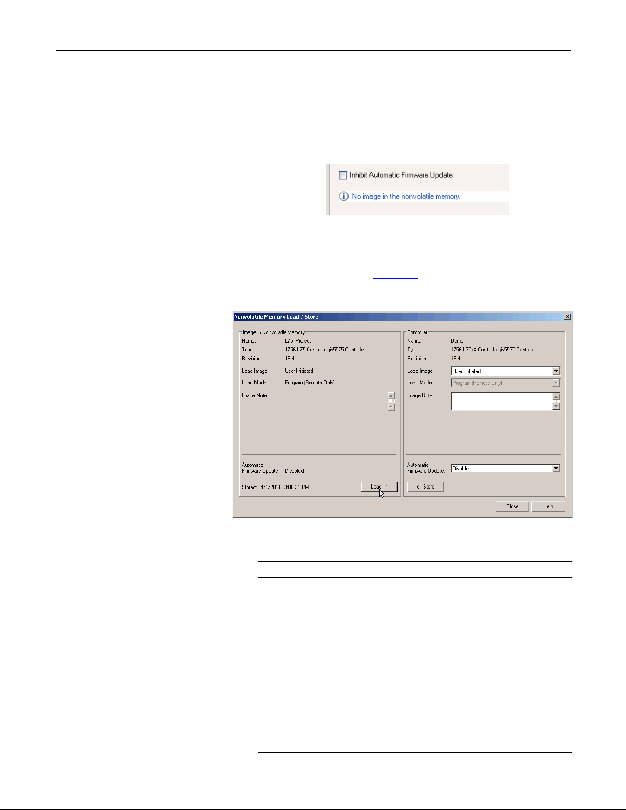
Start Using the Controller Chapter 3
TIP
TIP
3. Verify that the image in nonvolatile memory (that is, the project on the
memory card) is the project that you want to load.
If no project is stored on the memory card, a message in the lower-left corner
of the Nonvolatile Memory tab indicates that an image (or project) is not
available as shown here.
For information to change the project that is available to load from nonvolatile
memory, see the Logix5000™ Controllers Nonvolatile Memory Programming
Manual, publication 1756-PM017
.
4. Click Load.
After clicking Load, the project is loaded to the controller as indicated by
the controller status indicators.
.
With these controllers These indications show the store status
1756-L6x While the load is in progress, the following occurs:
1756-L7x While the load is in progress, the following occurs:
Rockwell Automation Publication 1756-UM001O-EN-P - October 2014 69
• OK indicator on the controller is flashing green
• A dialog box in the Logix Designer application indicates that the store is in
progress
When the load is complete, the following occurs:
• OK indicator on the controller is momentarily red, then solid green
• OK indicator is solid red
• SD indicator is flashing green
• LOAD is shown on the status display
• UPDT ca n be shown on the status display if t he firmware i s also updat ing with
the load
• A dialog box in the Logix Designer application indicates that the store is in
progress
When the load is complete, the following occurs:
• OK indicator on the controller is momentarily red, then solid green
• SD indicator on the controller is Off
Page 70

Chapter 3 Start Using the Controller
IMPORTANT
IMPORTANT
Allow the load to complete without interruption. If you interrupt the
load, data corruption or loss can occur.
Other Memory Card Tasks
Other tasks that you can complete by using the memory cards of the controller
include the following:
• Change the image that is loaded from the card
• Check for a load that was completed
• Clear an image from the memory card
• Store an empty image
• Change load parameters
• Read/write application data to the card
For more information to complete any of these tasks, see the Logix5000
Controllers Memory Card Programming Manual, publication 1756-PM017
.
Use ControlLogix Energy Storage Modules (ESMs)
You can use the ControlLogix ESMs to execute one of the following tasks:
• Provide power to 1756-L7x controllers to save the program to the on-
board nonvolatile storage (NVS) memory of the controller after power is
removed from the chassis or the controller is removed from a powered
chassis.
.
When you are using an ESM to save the program to on-board NVS
memory, you are not saving the program to the SD card installed in the
controller.
• Clear the program from the on-board NVS memory of the 1756-L7x
controller. For more information, see Clear the Program from On-board
NVS Memory.
The following table describes the ESMs.
Cat. No. Description
1756-ESMCAP Capacitor-based ESM
The 1756-L7x controllers come with this ESM installed.
1756-ESMNSE Capacitor-based ESM without WallClockTime back-up power
Use this ESM if your application requires that the installed ESM deplete its residual stored energy
to 40μjoules or less before transporting it into or out of your application. Additionally, you can
use this ESM with only a 1756-L73 (8 MB) or smaller memory-sized controller.
1756-ESMNRM Secure capacitor-based ESM (non-removable)
This ESM provides your application an enhanced degree of security by blocking physical access to
the USB connector and the SD card.
70 Rockwell Automation Publication 1756-UM001O-EN-P - October 2014
Page 71

Start Using the Controller Chapter 3
Save the Program to On-board NVS Memory
Follow these steps to save the program to NVS memory when the controller loses
power.
1. Remove power from the controller.
You can remove power in one of two ways:
• Turn power off to the chassis while the controller is installed in the
chassis.
• Remove the controller from a powered chassis.
Immediately after the controller is no longer powered, the program starts
saving while the OK status indicator is green (this green is a dimmer green
than normal operation), then turns red after program save is complete.
Once the ESM stops operating, it turns off.
The following graphic shows the OK status indicator on the controller.
2. Leave the ESM on the controller until the OK status indicator is Off.
Clear the Program from On-board NVS Memory
If your application lets you, follow these steps to clear the program from the onboard NVS memory of the 1756-L7x controller.
1. Remove the ESM from the controller.
2. Remove power from the controller.
You can remove power in one of the following two ways:
• Turn power off to the chassis while the controller is installed in the
chassis.
• Remove the controller from a powered chassis.
3. Reinstall the ESM into the controller.
4. Restore power to the controller in one of these two ways:
• If the controller is installed in the chassis, turn power back onto the
chassis.
• If the controller is not installed into the chassis, reinstall the controller
into the chassis and turn power back onto the chassis.
Rockwell Automation Publication 1756-UM001O-EN-P - October 2014 71
Page 72

Chapter 3 Start Using the Controller
IMPORTANT
Estimate the ESM Support of the WallClockTime
Maintain the Battery (Only 1756-L6x Controllers)
The ESM provides support for the maintenance of the WallClockTime of the
controller when power is not applied. Use this table to estimate the hold-up time
of the ESM based on the temperature of the controller and installed ESM.
Hold-up Time (in days)
Temperature 1756-ESMCAP 1756-ESMNRM 1756-ESMNSE
20
°C (68 °F) 12 12 0
40 °C (104 °F) 10 10 0
60 °C (140 °F) 7 7 0
Any action that causes the 1756-L7x controller to reset (hard or soft), without
an ESM installed, results in the controller’s wal clock time of the controller
being reset to the factory default of 01/01/1998.
To check the status of the ESM, see General Status Messages
on page 186.
This section explains how to monitor and maintain the lithium batteries that the
ControlLogix controllers support.
Table 6 - 1756-L6x Controllers and Compatible Batteries
Cat. No. Series Compatible Battery
1756-L61
1756-L62
1756-L63
1756-L61
1756-L62
1756-L63
1756-L64
1756-L65
1756-L63XT B
For further information, see the Additional Resources
A 1756-BA1
or
1756-BATA
or
1756-BATM
B 1756-BA2
section in the preface.
Check the Battery Status
When the battery is approximately 95% discharged, these low-battery warnings
are indicated:
• The BAT is solid red.
• A minor fault (type 10, code 10) is logged.
72 Rockwell Automation Publication 1756-UM001O-EN-P - October 2014
Page 73

Start Using the Controller Chapter 3
EXAMPLE
IMPORTANT
If the temperature 2.54 cm (1 in.)
below the chassis is
Replace the battery within
-25…35 °C (-13…95 °F) No replacement required
36…40 °C (96.8…104 °F) 3 years
41…45 °C (105.8…113 °F) 2 years
46…50 °C (114.8…122 °F) 16 months
51…55 °C (123.8…131 °F) 11 months
56…70 °C (132.8…158 °F) 8 months
IMPORTANT: To prevent possible battery leakage, even if the BAT status
indicator is off, replace a battery according to this schedule.
1756-BA1 or 1756-BATA Battery Life
To estimate how long a 1756-BA1 or 1756-BATA battery can support controller
memory on 1756-L6x, series A controllers, perform this procedure.
1. Determine the temperature 2.54 cm (1 in.) below the chassis.
2. Determine the weekly percentage of time that the controller is turned on.
If a controller is Off at one of these times:
• 8 hr/day during a 5-day work week
• All day Saturday and Sunday
Then the controller is off 52% of the time:
• Total hours per week = 7 x 24 = 168 hrs
• Total off hours per week = (5 days x 8 hr/day) + Saturday +
Sunday = 88 hrs
• Percentage off time = 88/168 = 52%
3. Determine the estimated worst-case battery life before and after the BAT
status indicator turns on.
4. For each year of battery life, decrease the time before the BAT status
indicator turns on by the percentage that is shown in the table.
Do not decrease the time after the BAT status indicator turns on.
If the BAT status indicator turns on when you apply power to the
controller, the remaining battery life can be less than Tab le 7
indicates.
Some of the battery life can be used up while the controller is off and
unable to turn on the BAT status indicator.
Rockwell Automation Publication 1756-UM001O-EN-P - October 2014 73
Page 74

Chapter 3 Start Using the Controller
IMPORTANT
Table 7 - Worst-case Estimates of 1756-BA1 Battery Life
Temperature Battery Life Before BAT Status Indicator Turns On Battery Life After BAT Status
Power Off 100% Power Off 50% Yearly Decrease
60 °C (140 °F) 22 days 43 days 23% 6 hrs
25 °C (77 °F) 21 days 42 days 17% 28 hrs
0 °C (32 °F) 14 days 28 days 17% 2.5 days
Indicator Turns On and Power is Off
Table 8 - Worst-case Estimates of 1756-BATA Battery Life
Temperature Battery Life Before BAT Status Indicator Turns On Battery Life After BAT Status
Power Off 100% Power Off 50% Yearly
Decrease
60 °C (140 °F) 98 days 204 days 11% 104 days
25 °C (77 °F) 146 days 268 days 5% 157 days
0 °C (32 °F) 105 days 222 days 6% 113 days
Indicator Turns On and Power is Off
1756-BATM Battery Module and Battery Life
Use the 1756-BATM battery module with any 1756-L6x/A controller. The
battery module is highly recommended for higher-memory controllers.
If your project is not stored in nonvolatile memory, the use of the battery
module is highly recommended.
When the 1756-BATA battery within the 1756-BATM module is approximately
50% discharged, these low-battery warnings are indicated:
• The BAT is solid red.
• A minor fault (type 10, code 10) is logged.
74 Rockwell Automation Publication 1756-UM001O-EN-P - October 2014
Page 75

Estimate 1756-BA2 Battery Life
The 1756-BA2 batteries are for use in 1756-L6x/B controllers. Use Ta b l e 9 to
estimate how much time can elapse before the battery becomes low.
Table 9 - Worst-case Estimates of 1756-BA2 Life according to Temperatures and Power Cycles
Start Using the Controller Chapter 3
Temperature 2.54 cm (1 in.) Below
the Chassis, max
-25…35 °C (-13…95 °F) 3 per day 3 years 3 years 26 months 20 months 10 months
41…45 °C (105.8…113 °F) 3 per day 2 years 2 years 2 years 20 months 10 months
46…50 °C (105.8…113 °F) 3 per day or less 16 months 16 months 16 months 16 months 10 months
51…55 °C (123.8…131 °F) 3 per day or less 11 months 11 months 11 months 11 months 10 months
56…70 °C (132.8…158 °F) 3 per day or less 8 months 8 months 8 months 8 months 8 months
Power Cycles Battery Life Before the BAT Status Indicator Turns Red
Project Size
1 MB 2 MB 4 MB 8 MB 16 MB
2 per day or less 3 years 3 years 3 years 31 months 16 months
2 per day or less 2 years 2 years 2 years 2 years 16 months
Rockwell Automation Publication 1756-UM001O-EN-P - October 2014 75
Page 76

Chapter 3 Start Using the Controller
IMPORTANT
EXAMPLE
Estimate 1756-BA2 Battery Life After Warnings
Use this table to estimate the battery life after the low-battery warnings are
indicated. Use these times even if the controller does not have power because
there is a small power-drain on the battery.
When you power up the controller, see if there is a low-battery warning. If
you get a low-battery warning for the first time, you have less battery life
than this table shows. While powered down, the controller still drains the
battery but it cannot give the low-battery warning.
Temperature 2.54 cm (1 in.)
Below the Chassis, max
0…20 °C (32…68 °F) 3 per day 26 weeks 18 weeks 12 weeks 9 weeks 5 weeks
21…40 °C (69.8…104 °F) 3 per day 18 weeks 14 weeks 10 weeks 8 weeks 5 weeks
41…45 °C (105.8…113 °F) 3 per day 12 weeks 10 weeks 7 weeks 6 weeks 4 weeks
46…50 °C (105.8…113 °F) 3 per day 10 weeks 8 weeks 6 weeks 6 weeks 3 weeks
51…55 °C (123.8…131 °F) 3 per day 7 weeks 6 weeks 5 weeks 4 weeks 3 weeks
56…60 °C (132.8…140 °F) 3 per day 5 weeks 5 weeks 4 weeks 4 weeks 2 weeks
Power Cycles Battery Life After the BAT Status Indicator Turns Red (worst case)
Project Size
1 MB 2 MB 4 MB 8 MB 16 MB
1 per day 26 weeks 26 weeks 26 weeks 22 weeks 13 weeks
1 per month 26 weeks 26 weeks 26 weeks 26 weeks 26 weeks
1 per day 24 weeks 21 weeks 18 weeks 16 weeks 11 weeks
1 per month 26 weeks 26 weeks 26 weeks 26 weeks 26 weeks
1 per day 15 weeks 14 weeks 12 weeks 11 weeks 8 weeks
1 per month 17 weeks 17 weeks 17 weeks 17 weeks 16 weeks
1 per day 12 weeks 11 weeks 10 weeks 9 weeks 7 weeks
1 per month 12 weeks 12 weeks 12 weeks 12 weeks 12 weeks
1 per day 8 weeks 8 weeks 7 weeks 7 weeks 5 weeks
1 per month 8 weeks 8 weeks 8 weeks 8 weeks 8 weeks
1 per day 6 weeks 6 weeks 5 weeks 5 weeks 4 weeks
1 per month 6 weeks 6 weeks 6 weeks 6 weeks 6 weeks
Under these conditions, the battery lasts at least 20 months before the BAT
status indicator turns red:
• The maximum temperature 2.54 cm (1 in.) below the
chassis = 45 °C (113 °F).
• You cycle power to the controller three times per day.
• The controller contains an 8 MB project.
76 Rockwell Automation Publication 1756-UM001O-EN-P - October 2014
Page 77

Battery Storage and Disposal
Follow these general rules to store your batteries:
• Store batteries in a cool, dry environment. We recommend
25 °C (77 °F) with 40…60% relative humidity.
• You can store batteries for up to 30 days in temperatures from
-45…85 °C (-49…185 °F), such as during transportation.
• To avoid leakage or other hazards, do not store batteries above
60 °C (140 °F) for more than 30 days.
This product contains a sealed lithium battery that needs to be replaced
during the life of the product.
At the end of its life, the battery contained in this product should be
collected separately from any unsorted municipal waste.
The collection and recycling of batteries helps protect the environment and
contributes to the conservation of natural resources as valuable materials
are recovered.
Start Using the Controller Chapter 3
Rockwell Automation Publication 1756-UM001O-EN-P - October 2014 77
Page 78

Chapter 3 Start Using the Controller
Notes:
78 Rockwell Automation Publication 1756-UM001O-EN-P - October 2014
Page 79

ControlLogix System and Controllers
L75
Input
Output
Output
Input
L75
Input
Top ic Pag e
ControlLogix System 79
Design a ControlLogix System 81
ControlLogix Controller Features 82
Chapter 4
ControlLogix System
The ControlLogix system is chassis-based and provides the option to configure a
control system that uses sequential, process, motion, drive control, and
communication and I/O capabilities.
Configuration Options
This section describes some of the many system configuration options that are
available with ControlLogix controllers.
Standalone Controller and I/O
One of the simplest ControlLogix configurations is a standalone controller with
I/O assembled in one chassis.
Figure 7 - Standalone Controller and I/O
Multiple Controllers in One Chassis
For some applications, multiple controllers can be used in one ControlLogix
chassis. For example, for better performance, multiple controllers can be used in
motion applications.
Rockwell Automation Publication 1756-UM001O-EN-P - October 2014 79
Page 80

Chapter 4 ControlLogix System and Controllers
L75
L75
EN2T
EN2T
FactoryTalk ®Server
Stratix 8000™ Switch
Kinetix 6500 Drive
Kinetix® 6500 Drive
Kinetix 6500 Drive
Motor
Motor
Motor
Ethernet
Ethernet
Figure 8 - Multiple Controllers in One Chassis
Multiple Devices Connected Via Multiple Networks
For some applications, various devices can be connected to the ControlLogix
chassis via multiple communication networks. For example, a system can be
connected to the following:
• Distributed I/O via an Ethernet network
• A PowerFlex® drive connected via a DeviceNet network
• Flowmeters that are connected via a HART connection
80 Rockwell Automation Publication 1756-UM001O-EN-P - October 2014
Page 81

ControlLogix System and Controllers Chapter 4
HART
L75
EN2T
DNB
CN2
EN2T
IF8H
PowerFlex Drive
DeviceNet
FLEX™ I/O
Contro lNet
Ethernet Device-level
Ring Network
Ethernet
HART
Endress + Hauser Flowmeters
FactoryTalk Server
POINT I/O™
Figure 9 - Multiple Devices Connected Via Multiple Networks
Design a ControlLogix System
When you design a ControlLogix system, there are several system components to
consider for your application. Some of these components include the following:
• I/O devices
• Motion control and drive requirements
• Communication modules
• Controllers
• Chassis
• Power supplies
• Studio 5000 environment
For more information to design and select components for your ControlLogix
system, see the ControlLogix Selection Guide, publication
1756-SG001
See the Additional Resources
.
section in the preface for more information if you
are designing your ControlLogix System for any of the following applications:
• Motion with Integrated Motion on the EtherNet/IP network
• Motion with the use of a coordinate system
• Motion with sercos or analog motion
Rockwell Automation Publication 1756-UM001O-EN-P - October 2014 81
Page 82

Chapter 4 ControlLogix System and Controllers
• Enhanced redundancy
• Standard redundancy
• SIL2
• SIL2 fault-tolerant I/O with Studio 5000 subroutines
• SIL2 fault-tolerant I/O with Studio 5000 Add-On Instructions
ControlLogix Controller Features
The ControlLogix controllers are part of the Logix5000 family of controllers
that are offered by Rockwell Automation. The sections that follow describe the
differentiating features of the ControlLogix controllers.
System, Communication, and Programming Features
Ta b l e 1 0 lists the system, communication, and programming features available
with ControlLogix controllers.
Table 10 - ControlLogix Controller Features
Feature 1756-L61, 1756-L62, 1756-L63,
Controller tasks • 32 tasks
Communication ports 1 port - RS-232 serial 1 port - USB, 2.0 full-speed, Type B
Communication options • EtherNet/IP
Serial port communication • ASCII
Controller connections suppor ted, max 250 500
Network connections, per network
module
Controll er redundanc y Full support except for motion applications
Integrated motion • Integrated Motion on the EtherNet/IP network
Programming languages • Relay ladder
1756-L64, 1756-L65
• 100 programs/task
• Event tasks: all event triggers
• Control Net
• DeviceNet
• Data Highway Plus™
• Remote I/O
• SynchLink
• Third-party process and device networks
• DF1 full/half-duplex
• DF1 radio modem
• DH-485
• Modbus via logic
• 128 ControlNet (1756-CN2/B)
• 100 ControlNet (1756-CN2/A)
• 40 ControlNet (1756-CNB)
• 256 EtherNet/IP; 128 TCP (1756-EN2x)
• 128 EtherNet/IP; 64 TCP (1756-ENBT)
• Sercos interface
• Analog options:
– Encoder input
– LDT input
– SSI input
• Structured text
• Function block
• Sequential function chart (SFC)
1756-L71, 1756-L72, 1756-L73,
1756-L74, 1756-L75
• 32 tasks
• 1000 programs/task
• Event tasks: all event triggers
N/A
82 Rockwell Automation Publication 1756-UM001O-EN-P - October 2014
Page 83

ControlLogix System and Controllers Chapter 4
IMPORTANT
IMPORTANT
Memory Options
The ControlLogix controller is available in different combinations of user
memory. Use Ta b l e 1 1
requirements.
.
Table 11 - ControlLogix Controller Memory Options
Controller Memory for Data and Logic I/O Back-up Memory
1756-L61 2 MB 478 KB CompactFlash card
1756-L62 4 MB
1756-L63, 1756-L63XT 8 MB
1756-L64 16 MB
1756-L65 32 MB
1756-L71 2 MB 0.98 MB (1006 KB) SD card
1756-L72 4 MB
1756-L73, 1756-L73XT 8 MB
1756-L74 16 MB
1756-L75 32 MB
to determine which controller meets your memory
(1)
(1) These nonvolatile memory cards are optional and do not come with the controller.
The 1756-L7x controllers ship with an SD card installed. We recommend that
you leave the SD card installed, so if a fault occurs, diagnostic data is
automatically written to the card and Rockwell Automation can use the data to
troubleshoot the anomaly.
We recommend that you use the SD cards available from Rockwell Automation
(catalog numbers 1784-SD1 or 1784-SD2).
While other SD cards can be used with the controller, Rockwell Automation has
not tested the use of those cards with the controller. If you use an SD card other
than those cards that are available from Rockwell Automation, you can
experience data corruption or loss.
Also, SD cards that are not provided by Rockwell Automation can have different
industrial, environmental, and certification ratings as those cards that are
available from Rockwell Automation and can have difficulty with survival in
the same industrial environments as the industrially rated versions available
from Rockwell Automation.
Rockwell Automation Publication 1756-UM001O-EN-P - October 2014 83
Page 84

Chapter 4 ControlLogix System and Controllers
IMPORTANT
Electronic Keying
Electronic Keying reduces the possibility that you use the wrong device in a
control system. It compares the device that is defined in your project to the
installed device. If keying fails, a fault occurs. These attributes are compared.
Attribute Description
Vendor The device manufacturer.
Device Type The general type of the product, for example, digital I/O module.
Product Code The specific type of the product. The Product Code maps to a catalog number.
Major Revision A number that represents the functional capabilities of a device.
Minor Revision A number that represents behavior changes in the device.
The following Electronic Keying options are available.
Keying Option Description
Compatible
Module
Disable Keying Indicates that the keying attributes are not considered when attempting to communicate with a
Exact Match Indicates that all keying attributes must match to establish communication. If any attribute does
Lets the installed device accept the key of the device that is defined in the project when the
installed device can emulate the defined device. With Compatible Module, you can typically
replace a device with another device that has the following characteristics:
• Same catalog number
• Same or higher Major Revision
• Minor Revision as follows:
– If the Major Revision is the same, the Minor Revision must be the same or higher.
– If the Major Revision is higher, the Minor Revision can be any number.
device. With Disable Keying, communication can occur with a device other than the type specified
in the project.
ATT EN TI ON : Be extremely cautious when using Disable Keying; i f used incorrectly, this option can
lead to personal injury or death, property damage, or economic loss.
We strongly recommend that you do not use Disable Keying.
If you use Disable Keying, you must take full responsibility for understanding whether the device
being used can fulfill the functional requirements of the application.
not match precisely, communication with the device does not occur.
Carefully consider the implications of each keying option when selecting one.
Changing Electronic Keying parameters online interrupts connections to the device and
any devices that are connected through the device. Connections from other controllers
can also be broken.
If an I/O connection to a device is interrupted, the result can be a loss of data.
More Information
For more detailed information on Electronic Keying, see Electronic Keying in
Logix5000 Control Systems Application Technique, publication LOGIX-
AT001.
84 Rockwell Automation Publication 1756-UM001O-EN-P - October 2014
Page 85

Communication Networks
Top ic Pag e
Networks Available 85
EtherNet/IP Network Communication 86
ControlNet Network Communication 89
DeviceNet Network Communication 92
Data Highway Plus (DH+) Network Communication 95
Universal Remote I/O (RIO) Communication 97
Foundation Fieldbus Communication 98
HART Communication 99
Chapter 5
Networks Available
Several communication networks are available for use with ControlLogix
systems. Ta b l e 1 2
describes typical network applications that are used with
ControlLogix systems and lists the networks available to support such
applications.
Table 12 - Applications and Supported Networks
Application Type Supported Networks
Integrated Motion EtherNet/IP
Integrated Motion on the EtherNet/IP network for time
synchronization
Control of distributed I/O • Control Net
Produce/consume data between controllers • Con trolNet
Messaging to and from other devices, including access to
the controller via Logix Designer application
EtherNet/IP
• DeviceNet
• EtherNet/IP
• Foundation Fieldbus
• HART
• Universal remote I/O
• EtherNet/IP
• Control Net
• DeviceNet (only to devices)
• Data Highway Plus (DH+)
• DH-485
• EtherNet/IP
• Serial
For more information about network design for your system, see the Ethernet
Design Considerations Reference Manual, publication ENET-RM002
Rockwell Automation Publication 1756-UM001O-EN-P - October 2014 85
.
Page 86

Chapter 5 Communication Networks
LINK NET OK
LINK NET OK
02
0
1734-AENTR
Module
Status
Network
Activity
Network
Status
Point Bus
Status
System
Power
Field
Power
POINT I O
Link 1
Activity/
Status
Link 2
Activity/
Status
IP ADDRESS
• Control Logix
• 1756-EN2T
CompactLogix™
PowerFlex 700S
Switch
1794-AENT
1756-EN2T
Distributed I/O
1734-AENT
Wor kst ati on
Device Level Ring (DLR) Topology
connected via 1783-ETAP with tap
EtherNet/IP Network Communication
The EtherNet/IP network offers a full suite of control, configuration, and data
collection services by layering the Common Industrial Protocol (CIP) over the
standard internet protocols, such as TCP/IP and UDP. This combination of
well-accepted standards provides the capability that is required to support
information data exchange and control applications.
The EtherNet/IP network uses commercially available Ethernet components and
physical media, providing you with a cost-effective plant-floor solution.
Figure 10 - EtherNet/IP Network Example
For more information about using EtherNet/IP modules, see the EtherNet/IP
Modules in Logix5000 Control Systems User Manual, publication
ENET-UM001
.
ControlLogix EtherNet/IP Module Features
The ControlLogix EtherNet/IP communication modules provide these features:
• Support for messaging, produced/consumed tags, HMI, and
distributed I/O
• The ability to encapsulate messages within the standard TCP/UDP/IP
protocol
86 Rockwell Automation Publication 1756-UM001O-EN-P - October 2014
Page 87

Communication Networks Chapter 5
• A common application layer with ControlNet and DeviceNet networks
• Network connections via an RJ45 cable
• Support half/full duplex 10 MB or 100 MB operation
• Support standard switches
ControlLogix EtherNet/IP Communication Modules
For EtherNet/IP network communication in a ControlLogix system, you have
several modules to choose from. Ta b l e 1 3
features.
Table 13 - EtherNet/IP Communication Modules and Capabilities
Module Is used to
1756-ENBT • Connect controllers to I/O modules (requires an adapter for distributed I/O).
• Communicate with other EtherNet/IP devices (messages).
• Serve as a pathway to share data between Logix5000 controllers (produce/consume).
• Bridge EtherNet/IP nodes to route messages to devices on other networks.
1756-EN2T • Perform the same functions as a 1756-ENBT module, with twice the capacity for more
demanding applications.
• Provide a temporary configuration connection via the USB por t.
• Configure IP addresses quickly by using rotary switches.
1756-EN2F • Perform the same functions as a 1756-EN2T module.
• Connect fiber media by an LC fiber connector on the module.
1756-EN2TR • Perform the same functions as a 1756-EN2T module.
• Support communication on a ring topology for a Device Level Ring (DLR) single-fault
tolerant ring network.
1756-EN2TRXT • Perform the same functions as a 1756-EN2T module.
• Support communication on a ring topology for a Device Level Ring (DLR) single-fault
tolerant ring network.
• Operate in extreme environments with -25…70 °C (-13…158 °F) temperatures.
1756-EN3TR • Perform the same functions as the 1756-EN2TR module.
• Extended Integrated Motion on EtherNet/IP network.
• Support of up to 128 motion axes.
1756-EN2TSC • Perform the same functions as a 1756-ENBT module, with twice the capacity for more
demanding applications.
• Provide a temporary configuration connection via the USB por t.
• Configure IP addresses quickly by using rotary switches.
1756-EN2TXT • Perform the same functions as a 1756-EN2T module.
• Operate in extreme environments with -25…70 °C (-13…158 °F) temperatures.
1756-EWEB • Provide customizable web pages for external access to controller information.
• Provide remote access via an internet browser to tags in a local ControlLogix controller.
• Communicate with other EtherNet/IP devices (messages).
• Bridge EtherNet/IP nodes to route messages to devices on other networks.
• Support Ethernet devices that are not EtherNet/IP-based with a socket inter face.
This module does not provide support for I/O or produced/consumed tags.
lists modules and their primary
Rockwell Automation Publication 1756-UM001O-EN-P - October 2014 87
Page 88

Chapter 5 Communication Networks
Software for EtherNet/IP Networks
Ta b l e 1 4 lists software that is used with the EtherNet/IP networks and modules
.
Table 14 - Software for Use with EtherNet/IP Networks
Software Is used to Required or Optional
Logix Designer application • Configure ControlLogix projects.
RSLinx Classic or RSLinx®
Enterprise
BOOTP/DHCP Utility Assign IP addresses to devices on an EtherNet/IP network. Optional
RSNetWorx™ for EtherNet/IP • Configure EtherNet/IP devices by IP addresses and/or
• Define EtherNet/IP communication.
• Configure communication devices.
• Provide diagnostics.
• Establish communication between devices.
host names.
• Provide bandwidth status.
Required
Required
Connections Over an EtherNet/IP Network
You indirectly determine the number of connections the controller uses by
configuring the controller to communicate with other devices in the system.
Connections are allocations of resources that provide more reliable
communication between devices as compared to unconnected messages.
All EtherNet/IP connections are unscheduled. The requested packet interval
(RPI) for I/O control or the program, such as a MSG instruction triggers an
unscheduled connection. Unscheduled messaging lets you send and receive data
when needed.
Double Data Rate (DDR) Backplane Communication
DDR communication can be achieved with the 1756-L7x controller. The
following communication modules support DDR when used with the 1756-L7x
controller. Minimum series are indicated as follows:
• 1756-EN2T/C
• 1756-EN2TR/B
• 1756-EN2TF/B
• 1756-EN2TXT/C
• 1756-EN3TR/A
• 1756-RM/B
DDR communication is achieved most efficiently when all modules in the
communication path are DDR modules, or, in other words, as one conversation
(connection) only between DDR modules.
DDR communication is achievable in a chassis with a mix of DDR and nonDDR modules. The DDR communication occurs between the modules that
88 Rockwell Automation Publication 1756-UM001O-EN-P - October 2014
Page 89

Communication Networks Chapter 5
support it. If non-DDR modules are also in the chassis, communication between
those modules is at the non-DDR rate.
For example, you can have a chassis with two 1756-L7x controllers in slots 0 and
1 communicating with each other by using DDR, and two 1756-L6x controllers
in slots 2 and 3 communicating by using non-DDR.
When multicast communication is used within a chassis to multiple modules, the
transmission rate is limited to the slowest module—or at the non-DDR rate.
For example, if a 1756-L7x controller is producing a tag to a 1756-L7x controller
and a 1756-L6x controller on the same multicast connection, it must use the
non-DDR rate.
ControlNet Network Communication
The ControlNet network is a real-time control network that provides high-speed
transport of time-critical I/O and interlocking data and messaging data. This
includes the upload and download of program and configuration data on one
physical-media link. The highly efficient data transfer capability of the
ControlNet network significantly enhances I/O performance and peer-to-peer
communication in any system or application.
The ControlNet network is highly deterministic and repeatable and is unaffected
when devices are connected or disconnected from the network. This quality
results in dependable, synchronized, and coordinated real-time performance.
The ControlNet network often functions as the following:
• A substitute/replacement for the remote I/O (RIO) network because the
ControlNet network adeptly handles large numbers of I/O points
• A backbone for multiple distributed DeviceNet networks
• A peer interlocking network
Rockwell Automation Publication 1756-UM001O-EN-P - October 2014 89
Page 90

Chapter 5 Communication Networks
ControlNe t
Distributed I/O
• 1756-CNB
• 1756 I/O
• 1794-ACN15
• 1794 I/O
Wor kst ati on
Compac tLogix
FlexLogix
• 1734-ACNR
• 1734 I/O
Panel View
PLC-5/40C15
PowerFlex 700S
Figure 11 - ControlNet Network Overview
In this example, these actions occur via the ControlNet network:
• The controllers produce and consume tags.
• The controllers initiate MSG instructions that do the following:
– Send and receive data.
– Configure devices.
• The workstation is used to do the following:
– Configure the ControlNet devices and the ControlNet network.
– Download and upload projects from the controllers.
For more information about using ControlNet modules, see ControlNet
Modules in Logix5000 Control Systems User Manual, publication
CNET-UM001
.
ControlLogix ControlNet Module Features
The ControlNet communication modules provide these features:
• Support for messaging, produced/consumed tags, and distributed I/O
• Use a common application layer with DeviceNet and EtherNet/IP
90 Rockwell Automation Publication 1756-UM001O-EN-P - October 2014
networks
• Requires no routing tables
• Support the use of coax and fiber repeaters for isolation and increased
distance
• Support redundant media (only 1756-CNBR, 1756-CN2R, and
1756-CN2RXT modules)
Page 91

Communication Networks Chapter 5
ControlLogix ControlNet Modules
Ta b l e 1 5 lists the available ControlLogix ControlNet modules and their primary
features.
Table 15 - ControlNet Modules and Capabilities
Module Is used to
1756-CNB • Control I/O modules.
1756-CN2 • Perform the same functions as a 1756-CNB module.
1756-CN2R • Perform the same functions as a 1756-CN2 module.
1756-CN2RXT • Perform same functions as a 1756-CN2R module.
1756-CNBR • Perform the same functions as a 1756-CNB module.
• Communicate with other ControlNet devices (messages).
• Share data with other Logix5000 controllers (produce/consume).
• Bridge ControlNet links to route messages to devices on other networks.
• Provide twice the capacity for more demanding applications.
• Support redundant ControlNet media.
• Operate in extreme environments with -25…70 °C (-13…158 °F) temperatures.
• Support redundant ControlNet media.
Software for ControlNet Networks
Ta b l e 1 6 lists software that is used with the ControlNet networks and modules.
Table 16 - Software for Use with ControlNet Networks
Software Is used to Required or Optional
Logix Designer application • Configure ControlLogix projects.
• Define ControlNet communication.
RSNetWorx™ for ControlNet™ • Configure ControlNet devices.
• Schedule a network.
RSLinx Classic or Enterprise • Configure communication devices.
• Provide diagnostics.
• Establish communication between devices.
Required
Rockwell Automation Publication 1756-UM001O-EN-P - October 2014 91
Page 92

Chapter 5 Communication Networks
Connections Over a ControlNet Network
You indirectly determine the number of connections the controller uses by
configuring the controller to communicate with other devices in the system.
Connections are allocations of resources that provide communication between
devices as compared to unconnected messages.
Table 17 - ControlNet Connections
Connection Definition
Scheduled
(unique to a
Control Net
network)
Unscheduled An unscheduled connection is a message transfer between devices that the requested packet
A scheduled connection is unique to ControlNet communication. A scheduled connection lets you
send and receive data repeatedly at a predetermined interval, which is the requested packet
interval (RPI). For example, a connection to an I/O module is a scheduled connection because you
repeatedly receive data from the module at a specified inter val.
Other scheduled connections include connections to the following:
• Communication devices
• Produced/consumed tags
On a ControlNet network, you must use RSNetWorx for ControlNet software to enable all scheduled
connections and establish a network update time (NUT). A scheduled connection reserves network
bandwidth specifically to handle the connection.
interval (RPI) or the program, such as a MSG instruction, triggers. Unscheduled messaging allows
you to send and receive data when you must:
Unscheduled connections use the remainder of network bandwidth after scheduled connections
are allocated.
DeviceNet Network Communication
ControlNet Module Connections
The 1756-CNB and 1756-CNBR communication modules support 64 CIP
connections over a ControlNet network. However, for optimal performance,
configure a maximum of 48 connections for each module.
The 1756-CN2, 1756-CN2R, and 1756-CN2RXT communication modules
support 128 connections over a ControlNet network, all of which can be
configured without risk of performance degradation.
The DeviceNet network uses the Common Industrial Protocol (CIP) to provide
the control, configuration, and data collection capabilities for industrial devices.
The DeviceNet network uses the proven Controller Area Network (CAN)
technology, which lowers installation costs and decreases installation time and
costly downtime.
A DeviceNet network provides access to the intelligence present in your devices
by letting you connect devices directly to plant-floor controllers without having
to hard-wire each device into an I/O module.
With a ControlLogix system, DeviceNet communication requires the use of a
1756-DNB DeviceNet communication module.
92 Rockwell Automation Publication 1756-UM001O-EN-P - October 2014
Page 93

Figure 12 - ControlLogix DeviceNet Network Overview
• Control Logix
• 1756-ENBT
Power Flex
Motor
Starter
Input/output Devices
Sensor
Push Button
Cluster
Barcode
Scanner
Indicator
Lights
DeviceNet Network
1788-EN2DNR
Compac tLogix
FLEX I/O
EtherNet/IP Network
Personal Compute r
Communication Networks Chapter 5
In this example, the ControlLogix controller is connected to the DeviceNet
network and devices via the 1788-EN2DNR linking device.
For more information about using DeviceNet modules and devices, see
DeviceNet Modules in Logix5000 Control Systems User Manual, publication
DNET-UM004
ControlLogix DeviceNet Module Features
The DeviceNet communication module provides these features:
.
• Supports messaging to devices (not controller to controller)
• Shares a common application layer with ControlNet and EtherNet/IP
networks
• Offers diagnostics for improved data collection and fault detection
• Requires less wiring than standard, hard-wired systems
Rockwell Automation Publication 1756-UM001O-EN-P - October 2014 93
Page 94

Chapter 5 Communication Networks
ControlLogix DeviceNet Bridge Module and Linking Devices
Ta b l e 1 8 lists the available ControlLogix DeviceNet bridge and linking devices
that can be used with the DeviceNet network.
Table 18 - DeviceNet Communication Modules and Capabilities
Module/Device Is used to
1756-DNB • Control I/O modules.
• Communicate with other DeviceNet devices (via messages).
1788-EN2DNR Link an EtherNet/IP network to a DeviceNet network.
1788-CN2DN Link a ControlNet network to a DeviceNet network.
Software for DeviceNet Networks
Ta b l e 1 9 lists software that is used with the DeviceNet networks and modules.
Table 19 - Software for Use with DeviceNet Networks
Software Is used to Required or Optional
Logix Designer application • Configure ControlLogix projects.
• Define DeviceNet communication.
RSNetWorx™ for DeviceNet™ • Configure DeviceNet devices.
• Define the scan list for those devices.
RSLinx Classic or Enterprise • Configure communication devices.
• Provide diagnostics.
• Establish communication between devices.
Required
Connections Over DeviceNet Networks
The ControlLogix controller requires two connections for each 1756-DNB
module. One connection is for module status and configuration. The other
connection is a rack-optimized connection for the device data.
ControlLogix DeviceNet Module Memory
The 1756-DNB module has fixed sections of memory for the input and output
data of the DeviceNet devices on the network. Each device on your network
requires some input or output memory of the scanner. Some devices send and
receive data, so they need input and output memory. The 1756-DNB module
supports up to add the following :
• 124 DINTs of input data
• 123 DINTs of output data
94 Rockwell Automation Publication 1756-UM001O-EN-P - October 2014
Page 95
Communication Networks Chapter 5
Data Highway Plus (DH+) Network Communication
For DH+ network communication, you have two module options for use in the
ControlLogix chassis. Ta b l e 2 0
Table 20 - DH+ Modules and Capabilities
RIO Module Is used to
1756-DHRIO • Function as a remote I/O (RIO) scanner.
• Support 32 logical rack connections or 16 block transfer connections per channel.
• Establish connections between controllers and I/O adapters.
• Distribute control so that each controller has its own I/O.
1756-DHRIOXT • Function as a remote I/O (RIO) scanner.
• Support 32 logical rack connections or 16 block transfer connections per channel.
• Establish connections between controllers and I/O adapters.
• Distribute control so that each controller has its own I/O.
• Operate in extreme environments with -25…70 °C (-13…158 °F) temperatures.
lists the DH+ modules and capabilities.
For DH+ network communication, use a 1756-DHRIO or 1756-DHRIOXT
module in the ControlLogix chassis to exchange information between these
controllers:
• PLC and SLC controllers
• ControlLogix controllers and PLC or SLC controllers
• ControlLogix controllers
The DH+ network also provides the following:
• Data exchange between controllers
• Plant-wide data sharing
• Cellular level data sharing
You can connect a maximum of 32 stations to one DH+ link:
• Channel A supports 57.6 Kbps, 115.2 Kbps, and 230.4 Kbps.
• Channel B supports 57.6 Kbps and 115.2 Kbps.
Rockwell Automation Publication 1756-UM001O-EN-P - October 2014 95
Page 96

Chapter 5 Communication Networks
SLC™ 500
DH+ Network
Data Collection and Recipe
Management
PLC-5
ControlLog ix
Control Logix
DH+ Network
RSView®
SLC 500
PLC-5
RSView
Wor kst ati on
EtherNet/IP Network
Figure 13 - ControlLogix DH+ Network Communication Example
Communicate Over a DH+ Network
For the controller to communicate to a workstation or other device over a
DH+ network, use RSLinx Classic software to do the following:
The 1756-DHRIO or 1756-DHRIOXT module can route a message through
up to four communication networks and three chassis. This limit applies only to
the routing of a message and not to the total number of networks or chassis in a
system.
For more information to configure and use a DH+ network via the
1756-DHRIO or 1756-DHRIOXT module, see the Data Highway PlusRemote I/O Communication Interface Module User Manual, publication
1756-UM514
• Specify a unique link ID for each ControlLogix backplane and additional
network in the communication path.
• Configure the routing table for the 1756-DHRIO or 1756-DHRIOXT
module.
.
96 Rockwell Automation Publication 1756-UM001O-EN-P - October 2014
Page 97

Communication Networks Chapter 5
Universal Remote I/O Network
Control Logix
PLC-5
1746-ASB
1771-ASB
1794-ASB
Universal Remote I/O (RIO) Communication
For universal remote I/O communication, you have two module options for use
in the ControlLogix chassis. Ta b l e 2 1
Table 21 - RIO Modules and Capabilities
RIO Module Is used to
1756-RIO • Function as an RIO scanner and adapter.
• Support connections to 32 racks in any combination of rack size or block transfers.
• Update data to the ControlLogix controller by using scheduled connections.
1756-DHRIO • Function as an RIO scanner.
• Support 32 logical rack connections or 16 block transfer connections per channel.
• Establish connections between controllers and I/O adapters.
• Distribute control so that each controller has its own I/O.
1756-DHRIOXT • Function as an RIO scanner.
• Support 32 logical rack connections or 16 block transfer connections per channel.
• Establish connections between controllers and I/O adapters.
• Distribute control so that each controller has its own I/O.
• Operate in extreme environments with -25…70 °C (-13…158 °F) temperatures.
lists the RIO modules and capabilities.
When a channel on the 1756-DHRIO or 1756-DHRIOXT module is
configured for remote I/O, the module acts as a scanner for a universal remote I/
O network. The controller communicates to the module to send and receive the
I/O data on the universal remote I/O network.
The 1756-RIO module can act as a scanner or adapter on a remote I/O network.
The 1756-RIO module transfers digital, block transfer, analog, and specialty data
without message instructions.
Figure 14 - ControlLogix Universal Remote I/O Communication Example
Communicate Over a Universal Remote I/O Network
For the controller to control I/O over a universal remote I/O network, you must
complete these tasks.
Rockwell Automation Publication 1756-UM001O-EN-P - October 2014 97
Page 98

Chapter 5 Communication Networks
1. Configure the remote I/O adapter.
2. Lay out the remote I/O network cable.
3. Connect the remote I/O network cable.
4. Configure the scanner channel.
For more information to configure a remote I/O network with the 1756-RIO,
1756-DHRIO, or 1756-DHRIOXT modules, see these publications:
• Data Highway Plus-Remote I/O Communication Interface Module User
Manual, publication 1756-UM514
• ControlLogix Remote I/O Communication Module User Manual,
publication 1756-UM534
As you design your remote I/O network, remember the following:
• All devices that are connected to a remote I/O network must
communicate by using the same communication rate. These rates are
available for remote I/O:
Foundation Fieldbus Communication
– 57.6 Kbps
– 115.2 Kbps
– 230.4 Kbps
• You must assign unique partial and full racks to each channel used in
Remote I/O Scanner mode.
Both channels of a 1756-DHRIO or 1756-DHRIOXT module cannot
scan the same partial or full rack address. Both module channels can
communicate to 00…37 octal or 40…77 octal, but each channel can
communicate only with one address at a time in whichever of these two
ranges it falls.
Foundation Fieldbus is an open interoperable fieldbus that is designed for process
control instrumentation. The fieldbus devices that are described in Ta b l e 2 2
can
be connected to the ControlLogix controller via another network as shown in
the following example.
Table 22 - Fieldbus Devices and Capabilities
Fieldbus Device Is used to
1788-EN2FFR • Bridge an EtherNet/IP network to Foundation Fieldbus.
1788-CN2FFR • Connect via low-speed serial (H1) connections.
• Connect via a low-speed serial (H1) and high-speed Ethernet (HSE) network
connections.
• Access devices directly via an OPC server.
• Bridge a ControlNet network to a Foundation Fieldbus.
• Support redundant ControlNet media.
98 Rockwell Automation Publication 1756-UM001O-EN-P - October 2014
Page 99

Communication Networks Chapter 5
RSFieldbus™ Software
24V DC
Power
Supply
Power
Conditioner
Field Dev ice Field Devi ce
1788-EN2FFR Linking Device
• ControlLog ix
• 1756-ENBT
Foundation Fieldbus distributes and executes control in the device. The
Foundation Fieldbus linking device does the following:
• Bridges from an EtherNet/IP network to an H1 connection
• Accepts HSE or EtherNet/IP messages and converts them to the H1
protocol
Figure 15 - Foundation Fieldbus Example
HART Communication
For more information about using the Foundation Fieldbus devices available
from Rockwell Automation, see these publications:
• EtherNet/IP and ControlNet to FOUNDATION Fieldbus Linking
Device User Manual, publication 1788-UM057
• FOUNDATION Fieldbus Design Considerations Reference Manual,
publication PROCES-RM005
HART (Highway Addressable Remote Transducer) is an open protocol that is
designed for process control instrumentation.
Device Is used to
1756 analog HART I/O modules: • Act as HART master to allow communication with HART field devices.
ProSoft interface
MVI56-H ART
• Interface directly with field devices (through built-in HART modems), which
eliminates the need for external hardware and more wiring.
• Provide access to more field device data, including voltage and current
measurements.
• Directly connect asset management software to HART devices.
• Support differential wiring for environments where improved noise immunity is
needed (input modules).
• Acquire data or control application with slow update requirements, such as a
tank farm.
• Does no t require external hardware to access HART signal.
• Does not provide a direct connection to asset management software.
Rockwell Automation Publication 1756-UM001O-EN-P - October 2014 99
Page 100

Chapter 5 Communication Networks
• Control Logix
• 1756-IF8H or
• 1756-OF8H
HART Field Devices
The HART protocol combines digital signals with analog signals to ready the
digital signal for the Process Variable (PV). The HART protocol also provides
diagnostic data from the transmitter.
Figure 16 - HART Protocol Example
For more information about using the HART I/O modules, see the
ControlLogix HART Analog I/O Modules User Manual, publication
1756-UM533
.
For more information about the ProSoft HART interface, see the
ProSoftTechnologies
website at http://www.prosoft-technology.com.
100 Rockwell Automation Publication 1756-UM001O-EN-P - October 2014
 Loading...