

Page 1

SLC
™
500
4-Channel
Thermocouple/mV
Input Module
(Catalog Number 1746-NT4,
Series B)
User Manual
Page 2
Important User Information
Solid state equipment has operational characteristics differing from those of
electromechanical equipment. Safety Guidelines for the Application,
Installation and Maintenance of Solid State Controls (Publication SGI-1.1
available from your local Rockwell Automation sales office or online at
http://www.ab.com/manuals/gi) describes some important differences
between solid state equipment and hard-wired electromechanical devices.
Because of this difference, and also because of the wide variety of uses for
solid state equipment, all persons responsible for applying this equipment
must satisfy themselves that each intended application of this equipment is
acceptable.
In no event will Rockwell Automation, Inc. be responsible or liable for
indirect or consequential damages resulting from the use or application of
this equipment.
The examples and diagrams in this manual are included solely for illustrative
purposes. Because of the many variables and requirements associated with
any particular installation, Rockwell Automation, Inc. cannot assume
responsibility or liability for actual use based on the examples and diagrams.
No patent liability is assumed by Rockwell Automation, Inc. with respect to
use of information, circuits, equipment, or software described in this manual.
Reproduction of the contents of this manual, in whole or in part, without
written permission of Rockwell Automation, Inc. is prohibited.
Throughout this manual we use notes to make you aware of safety
considerations.
WARNING
IMPORTANT
ATTENTION
SHOCK HAZARD
BURN HAZARD
Identifies information about practices or circumstances
that can cause an explosion in a hazardous environment,
which may lead to personal injury or death, property
damage, or economic loss.
Identifies information that is critical for successful
application and understanding of the product.
Identifies information about practices or circumstances
that can lead to personal injury or death, property
damage, or economic loss. Attentions help you:
• identify a hazard
• avoid a hazard
• recognize the consequence
Labels may be located on or inside the drive to alert
people that dangerous voltage may be present.
Labels may be located on or inside the drive to alert
people that surfaces may be dangerous temperatures.
Page 3

Summary of Changes
The information below summarizes the changes to this manual since
the last printing.
To help you find new and updated information in this release of the
manual, we have included change bars as shown to the right of this
paragraph.
For information on: See page:
Changes to the SLC™ 500 Thermocouple/mV Input Module. throughout manual
Using RSLogix™ 500 to configure the NT4 module. 2-4, 5-2, 6-1, and Appendix
E
Maintaining the ambient temperature surrounding the SLC
500 above 3°C (37.4°F).
A-2
Publication 1746-UM007C-EN-P - July 2004
Page 4

2 Summary of Changes
Publication 1746-UM007C-EN-P - July 2004
Page 5

Overview
Quick Start for Experienced Users
Table of Contents
Preface
Who Should Use this Manual. . . . . . . . . . . . . . . . . . . . . . . P-1
Purpose of this Manual . . . . . . . . . . . . . . . . . . . . . . . . . . . P-1
Related Documentation . . . . . . . . . . . . . . . . . . . . . . . . P-2
Your Questions or Comments on this Manual . . . . . . . . P-3
Common Techniques Used in this Manual . . . . . . . . . . . . . P-3
Chapter 1
General Description . . . . . . . . . . . . . . . . . . . . . . . . . . . . . 1-1
Hardware Features. . . . . . . . . . . . . . . . . . . . . . . . . . . . 1-2
General Diagnostic Features. . . . . . . . . . . . . . . . . . . . . 1-3
System Overview . . . . . . . . . . . . . . . . . . . . . . . . . . . . . . . 1-3
System Operation . . . . . . . . . . . . . . . . . . . . . . . . . . . . 1-4
Module Operation . . . . . . . . . . . . . . . . . . . . . . . . . . . . 1-5
Thermocouple Compatibility . . . . . . . . . . . . . . . . . . . . 1-5
Linear Millivolt Device Compatibility. . . . . . . . . . . . . . . 1-7
Chapter 2
Required Tools and Equipment . . . . . . . . . . . . . . . . . . . . . 2-1
Installation Procedures . . . . . . . . . . . . . . . . . . . . . . . . . . . 2-2
Installation and Wiring
Preliminary Operating
Considerations
Chapter 3
Compliance to European Union Directives . . . . . . . . . . . . . 3-1
EMC Directive . . . . . . . . . . . . . . . . . . . . . . . . . . . . . . . 3-1
Electrostatic Discharge. . . . . . . . . . . . . . . . . . . . . . . . . . . . 3-2
NT4 Power Requirements . . . . . . . . . . . . . . . . . . . . . . . . . 3-2
Module Location in Chassis . . . . . . . . . . . . . . . . . . . . . . . . 3-3
Fixed Expansion Chassis Considerations . . . . . . . . . . . . 3-3
General Considerations . . . . . . . . . . . . . . . . . . . . . . . . 3-5
Module Installation and Removal. . . . . . . . . . . . . . . . . . . . 3-5
Terminal Block Removal . . . . . . . . . . . . . . . . . . . . . . . 3-6
Module Installation Procedure . . . . . . . . . . . . . . . . . . . 3-6
Module Removal Procedure . . . . . . . . . . . . . . . . . . . . . 3-7
Terminal Wiring . . . . . . . . . . . . . . . . . . . . . . . . . . . . . . . . 3-7
Wiring Considerations . . . . . . . . . . . . . . . . . . . . . . . . . 3-8
Wiring Input Devices to the NT4 . . . . . . . . . . . . . . . . . 3-11
Cold Junction Compensation (CJC) . . . . . . . . . . . . . . . . 3-12
Thermocouple Calibration . . . . . . . . . . . . . . . . . . . . . . . . . 3-13
Chapter 4
Module ID Code . . . . . . . . . . . . . . . . . . . . . . . . . . . . . . . . 4-1
Module Addressing . . . . . . . . . . . . . . . . . . . . . . . . . . . . . . 4-2
Output Image-Configuration Words . . . . . . . . . . . . . . . 4-2
Input Image-Data Words and Status Words . . . . . . . . . . 4-3
Channel Filter Frequency Selection . . . . . . . . . . . . . . . . . . 4-4
i Publication 1746-UM007C-EN-P - July 2004
Page 6

Table of Contents ii
Channel Configuration, Data, and
Status
Effective Resolution . . . . . . . . . . . . . . . . . . . . . . . . . . . 4-4
Channel Cut-Off Frequency . . . . . . . . . . . . . . . . . . . . . 4-5
Channel Step Response . . . . . . . . . . . . . . . . . . . . . . . . 4-6
Update Time. . . . . . . . . . . . . . . . . . . . . . . . . . . . . . . . . . . 4-7
Update Time Calculation Example . . . . . . . . . . . . . . . . 4-8
Channel Turn-On, Turn-Off, and Reconfiguration Times . . . 4-9
Response to Slot Disabling . . . . . . . . . . . . . . . . . . . . . . . . 4-10
Input Response . . . . . . . . . . . . . . . . . . . . . . . . . . . . . . 4-10
Output Response . . . . . . . . . . . . . . . . . . . . . . . . . . . . . 4-10
Chapter 5
Channel Configuration . . . . . . . . . . . . . . . . . . . . . . . . . . . 5-1
Channel Configuration Procedure . . . . . . . . . . . . . . . . . . . 5-2
Select Input Type (Bits 0-3) . . . . . . . . . . . . . . . . . . . . . 5-5
Select Data Format (Bits 4 and 5) . . . . . . . . . . . . . . . . . 5-5
Using Scaled-for-PID and Proportional Counts . . . . . . . 5-6
Scaling Examples . . . . . . . . . . . . . . . . . . . . . . . . . . . . . 5-7
Select Open Circuit State (Bits 6 and 7). . . . . . . . . . . . . 5-10
Select Temperature Units (Bit 8) . . . . . . . . . . . . . . . . . . 5-11
Select Channel Filter Frequency (Bits 9 and 10). . . . . . . 5-11
Select Channel Enable (Bit 11) . . . . . . . . . . . . . . . . . . . 5-12
Unused Bits (Bits 12-15). . . . . . . . . . . . . . . . . . . . . . . . 5-12
Channel Data Word. . . . . . . . . . . . . . . . . . . . . . . . . . . . . . 5-12
Channel Status Checking . . . . . . . . . . . . . . . . . . . . . . . . . . 5-13
Status Conditions . . . . . . . . . . . . . . . . . . . . . . . . . . . . . . . 5-15
Input Type Status (Bits 0-3) . . . . . . . . . . . . . . . . . . . . . 5-15
Data Format Type Status (Bits 4 and 5). . . . . . . . . . . . . 5-15
Open Circuit Type Status (Bits 6 and 7) . . . . . . . . . . . . 5-15
Temperature Units Type Status (Bit 8). . . . . . . . . . . . . . 5-16
Channel Filter Frequency (Bits 9 and 10) . . . . . . . . . . . 5-16
Channel Status (Bit 11). . . . . . . . . . . . . . . . . . . . . . . . . 5-16
Open-Circuit Error (Bit 12) . . . . . . . . . . . . . . . . . . . . . . 5-16
Under-Range Error (Bit 13). . . . . . . . . . . . . . . . . . . . . . 5-16
Over-Range Error (Bit 14). . . . . . . . . . . . . . . . . . . . . . . 5-17
Configuration Error (Bit 15) . . . . . . . . . . . . . . . . . . . . . 5-17
Ladder Programming Examples
Publication 1746-UM007C-EN-P - July 2004
Chapter 6
Initial Programming. . . . . . . . . . . . . . . . . . . . . . . . . . . . . . 6-1
Procedure . . . . . . . . . . . . . . . . . . . . . . . . . . . . . . . . . . 6-2
Dynamic Programming . . . . . . . . . . . . . . . . . . . . . . . . . . . 6-3
Verifying Channel Configuration Changes . . . . . . . . . . . . . 6-4
Interfacing to the PID Instruction. . . . . . . . . . . . . . . . . . . . 6-5
Monitoring Channel Status Bits . . . . . . . . . . . . . . . . . . . . . 6-6
Invoking Autocalibration . . . . . . . . . . . . . . . . . . . . . . . . . . 6-7
Page 7

Module Diagnostics and
Troubleshooting
Application Examples
Table of Contents iii
Chapter 7
Module Operation vs Channel Operation . . . . . . . . . . . . . . 7-1
Power-up Diagnostics . . . . . . . . . . . . . . . . . . . . . . . . . . . . 7-1
Channel Diagnostics . . . . . . . . . . . . . . . . . . . . . . . . . . . . . 7-2
LED Indicators . . . . . . . . . . . . . . . . . . . . . . . . . . . . . . . . . 7-3
Channel Status LEDs (Green) . . . . . . . . . . . . . . . . . . . . 7-4
Invalid Channel Configuration . . . . . . . . . . . . . . . . . . . 7-4
Open Circuit Detection . . . . . . . . . . . . . . . . . . . . . . . . 7-4
Out-Of-Range Detection. . . . . . . . . . . . . . . . . . . . . . . . 7-5
Module Status LED (Green) . . . . . . . . . . . . . . . . . . . . . 7-5
Troubleshooting Flowchart . . . . . . . . . . . . . . . . . . . . . . . . 7-6
Replacement Parts. . . . . . . . . . . . . . . . . . . . . . . . . . . . . . . 7-7
Contacting Rockwell Automation . . . . . . . . . . . . . . . . . . . . 7-7
Chapter 8
Basic Example . . . . . . . . . . . . . . . . . . . . . . . . . . . . . . . . . 8-1
Application Setup (Display a Temperature) . . . . . . . . . 8-1
Channel Configuration . . . . . . . . . . . . . . . . . . . . . . . . . 8-2
Supplementary Example . . . . . . . . . . . . . . . . . . . . . . . . . . 8-4
Application Setup (Four Channels °C - °F) . . . . . . . . . . 8-4
Device Configuration . . . . . . . . . . . . . . . . . . . . . . . . . . 8-4
Channel Configuration . . . . . . . . . . . . . . . . . . . . . . . . . 8-5
Program Setup and Operation Summary . . . . . . . . . . . . 8-7
Program Listing . . . . . . . . . . . . . . . . . . . . . . . . . . . . . . 8-7
Specifications
NT4 Configuration Worksheet
Thermocouple Restrictions
Appendix A
Electrical Specifications . . . . . . . . . . . . . . . . . . . . . . . . . . . A-1
Physical Specifications. . . . . . . . . . . . . . . . . . . . . . . . . . . . A-2
Environmental Specifications . . . . . . . . . . . . . . . . . . . . . . . A-2
Input Specifications. . . . . . . . . . . . . . . . . . . . . . . . . . . . . . A-3
1746-NT4 Module Accuracy . . . . . . . . . . . . . . . . . . . . . A-4
Input Resolution per Thermocouple Type at Each Filter
Frequency . . . . . . . . . . . . . . . . . . . . . . . . . . . . . . . . . . . . A-4
Appendix B
Channel Configuration Procedure . . . . . . . . . . . . . . . . . . . B-1
Channel Configuration Worksheet . . . . . . . . . . . . . . . . . . . B-4
Appendix C
J Type Thermocouple . . . . . . . . . . . . . . . . . . . . . . . . . . . . C-1
(Iron vs. Copper-Nickel <Constantan>) . . . . . . . . . . . . . C-1
K Type Thermocouple . . . . . . . . . . . . . . . . . . . . . . . . . . . C-2
(NIckel-Chromium vs. Nickel-Aluminum) . . . . . . . . . . . C-2
T Type Thermocouple. . . . . . . . . . . . . . . . . . . . . . . . . . . . C-3
Publication 1746-UM007C-EN-P - July 2004
Page 8

Table of Contents iv
Thermocouple Types
Configuring the 1746-NT4 Module
with RSLogix 500
(Copper vs. Copper-Nickel <Constantan>) . . . . . . . . . . C-3
E Type Thermocouple. . . . . . . . . . . . . . . . . . . . . . . . . . . . C-4
(Nickel-Chromium vs. Copper-Nickel <Constantan>) . . . C-4
S and R Type Thermocouples . . . . . . . . . . . . . . . . . . . . . . C-5
S (Platinum-10% Rhodium vs. Platinum)
R (Platinum-13% Rhodium vs. Platinum) . . . . . . . . . . . C-5
Appendix D
Appendix E
Glossary
Index
Publication 1746-UM007C-EN-P - July 2004
Page 9

Preface
Read this preface to familiarize yourself with the rest of the manual.
The preface includes:
• Who Should Use this Manual
• Purpose of this Manual
• Common Techniques Used in this Manual
Who Should Use this
Manual
Purpose of this Manual
Use this manual if you are responsible for designing, installing,
programming, or troubleshooting control systems that use SLC 500
4-Channel Thermocouple/mV Input Module.
You should have a basic understanding of electrical circuitry and
familiarity with relay logic. If you do not, obtain the proper training
before using this product.
This manual describes the procedures you use to install, wire, and
troubleshoot your 4-channel thermocouple/mV module. This manual:
• explains how to install and wire your module
• gives you an overview of the SLC 500 programmable controller
system
Refer to your programming software user documentation for more
information on programming your SLC 500 programmable controller.
1 Publication 1746-UM007C-EN-P - July 2004
Page 10

2 Preface
Related Documentation
The following documents contain additional information concerning
Rockwell Automation products. To obtain a copy, contact your local
Rockwell Automation office or distributor.
For Read this Document Document Number
In-depth information on the SLC Instruction Set. SLC 500 Instruction Set Reference Manual 1747-RM001
A description on how to install and use your Modular SLC 500
programmable controller.
A description on how to install and use your Fixed SLC 500
programmable controller.
A description on how to install the SLC 500 4-Channel
Thermocouple/mV input module
Information on reducing electrical noise. System Design for Control of Electrical
In-depth information on grounding and wiring Allen-Bradley®
programmable controllers.
A description of important differences between solid-state
programmable controller products and hard-wired electromechanical
devices.
An article on wire sizes and types for grounding electrical
equipment.
A glossary of industrial automation terms and abbreviations. Allen-Bradley Industrial Automation
SLC 500 Modular Hardware Style User
Manual
Installation & Operation Manual for Fixed
Hardware Style Programmable Controllers
SLC 500 4-Channel Thermocouple/mV
Module Installation Instructions
Noise
Allen-Bradley Programmable Controller
Grounding and Wiring Guidelines
Application Considerations for Solid-State
Controls
National Electrical Code - Published by the National Fire Protection
Association of Boston, MA.
Glossary
1747-UM011
1747-6.21
1746-IN010
GMC-RM001
1770-4.1
SGI-1.1
AG-7.1
Publication 1746-UM007C-EN-P - July 2004
Page 11

Preface 3
If you would like a manual, you can:
• download an electronic version from the internet at:
– www.theautomationbookstore.com
– http://www.ab.com/manuals
• order a printed manual by:
– contacting your local distributor or Rockwell Automation
representative
– visiting www.theautomationbookstore.com
– calling 1.800.963.9548 (USA/Canada) or 001.330.725.1574
(Outside USA/Canada)
Your Questions or Comments on this Manual
If you find a problem with this manual, or you have any suggestions
for how this manual could be made more useful to you, please
contact us at the address below:
Common Techniques Used
in this Manual
Rockwell Automation
Automation Control and Information Group
Technical Communication, Dept. A602V
P.O. Box 2086
Milwaukee, WI 53201-2086
The following conventions are used throughout this manual:
• Bulleted lists such as this one provide information, not
procedural steps.
• Numbered lists provide sequential steps or hierarchical
information.
• Italic type is used for emphasis.
Publication 1746-UM007C-EN-P - July 2004
Page 12

4 Preface
Publication 1746-UM007C-EN-P - July 2004
Page 13

Chapter
Overview
This chapter describes the thermocouple/millivolt module and
explains how the SLC controller gathers thermocouple or millivolt
initiated analog input from the module. This chapter includes:
• General Description
• System Overview
1
General Description
The thermocouple/mV module receives and stores digitally converted
thermocouple and/or millivolt (mV) analog data into its image table
for retrieval by all fixed and modular SLC 500 processors. The module
supports connections from any combination of up to four
thermocouple or mV analog sensors.
The following tables define thermocouple types and their associated
full scale temperature ranges and also list the millivolt analog input
signal ranges that each 1746-NT4 channel will support. To determine
the practical temperature range your thermocouple supports, refer to
the specifications in Appendix A.
Ty pe °C Temperature Range °F Temperature Range
J -210° to 760° -346° to 1400°
K -270° to 1370° -454° to 2498°
T -270° to 400° -454° to 752°
B 300° to 1820° 572° to 3308°
E -270° to 1000° -454° to 1832°
R 0° to 1768° 32° to 3214°
S 0° to 1768° 32° to 3214°
N 0° to 1300° 32° to 2372°
CJC Sensor 0° to 85° 32° to 185°
Millivolt Input Type Range
±50 mV -50 mV dc to +50 mV dc
±100 mV -100 mV dc to +100 mV dc
Each input channel is individually configurable for a specific input
device and provides open-circuit, over-range, and under-range
detection and indication.
1 Publication 1746-UM007C-EN-P - July 2004
Page 14
1-2 Overview
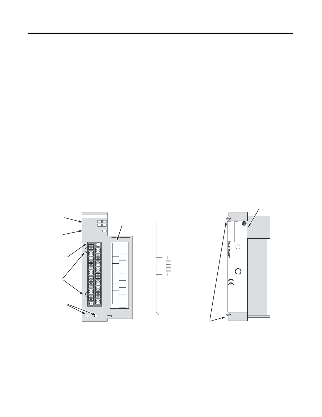
Hardware Features
The thermocouple module fits into any single-slot, except the
processor slot (0), in either an SLC 500 modular system or an SLC 500
fixed system expansion chassis (1746-A2). It is a Class 1 module (uses
8 input words and 8 output words). It interfaces to thermocouple
types J, K, T, E, R, S, B, and N, and supports direct ±50 mV and ±100
mV analog input signals.
The module requires the use of Block Transfer in a remote
configuration.
The module contains a removable terminal block providing
connection for four thermocouple and/or analog input devices. There
are also two, cold-junction compensation (CJC) sensors used to
compensate for offset voltages introduced into the input signal as a
result of the cold-junction, i.e., where the thermocouple wires connect
to the module wiring terminal. There are no output channels on the
module. Module configuration is done via the user program. There are
no DIP switches.
Channel Status
LEDs (Green)
Module Status
LED (Green)
Removable
Terminal Block
CJC Sensors
Cable Tie Slots
INPUT
CHANNEL
STATUS
MODULE
ST
ATUS
THERMOCOUPLE/mV
012
3
Door Label
CJC A+
Do Not
Remove
CHL0+
_
CJC A
Do Not
Remove
CHL0
SHIELD
CHL1+
SHIELD
_
CHL1
SHIELD
CHL2+
SHIELD
_
CHL2
SHIELD
CHL3+
_
CJC B
Do Not
CHL3
Remove
CJC B+
Do Not
Remove
ANLG
COM
Side Label
CAT
SERIAL
1746 NT4
NT4-xxx x
THERMOCOUPLE/mV INPUT MODULE
SLC 500
NO.
SER
FRN
®
CLASS I, GROUPS A, B, C AND D, DIV.2
U
L
FOR HAZ. LOC. A196
LISTED IND. CONT. EQ.
_
SA
®
OPERATING
TEMPERATURE
CODE T3C
FAC 1M
THERMOCOUPLE TYPES:
VOLTAGE:
INPUT SIGNAL RANGES
100mVDC to +100mVDC
_
50mVDC to +50mVDC
_
_
J, K, T, E, R, S, B, N
MADE IN USA
Self-Locking Tabs
Publication 1746-UM007C-EN-P - July 2004
Page 15
Hardware Function
Overview 1-3
Channel Status LED
Indicators
Module Status LED Displays module operating and fault status
Side Label (Nameplate) Provides module information
Removable Terminal Block Provides physical connection to input devices.
Door Label Permits easy terminal identification
Cable Tie Slots Secure and route wiring from module
Self-Locking Tabs Secure module in chassis slot
Display operating and fault status of
channels 0, 1, 2, and 3
It is color coded green.
General Diagnostic Features
The thermocouple/mV module contains diagnostic features that can
help you identify the source of problems that may occur during
power-up or during normal channel operation. These power-up and
channel diagnostics are explained in chapter 7, Module Diagnostics
and Troubleshooting.
System Overview
The thermocouple module communicates to the SLC 500 processor
through the parallel backplane interface and receives +5V dc and
+24V dc power from the SLC 500 power supply through the
backplane. No external power supply is required. You may install as
many thermocouple modules in your system as the power supply can
support.
SLC Processor
Thermocouple Modules
Publication 1746-UM007C-EN-P - July 2004
Page 16
1-4 Overview
Each individual channel on the thermocouple module can receive
input signals from thermocouple sensors or mV analog input devices.
You configure each channel to accept either input. When configured
for thermocouple input types, the thermocouple module converts the
analog input voltages into cold-junction compensated and linearized,
digital temperature readings. The 1746-NT4 uses the National Bureau
of Standards (NBS) Monograph 125 and 161 based on IPTS-68 for
thermocouple linearization.
When configured for millivolt analog inputs, the module converts the
analog values directly into digital values. The module assumes that the
mV input signal is already linear.
System Operation
At power-up, the thermocouple module performs a check of its
internal circuits, memory, and basic functions. During this time the
module status LED remains off. If no faults are found during the
power-up diagnostics, the module status LED is turned on.
Thermocouple or mV
Analog Signals
Thermocouple
Input
Module
Channel Data W
Channel
Channel
Configuration W
Status W
ord
ord
SLC 500
Processor
ord
After power-up checks are complete, the thermocouple module waits
for valid channel configuration data from your SLC ladder logic
program (channel status LEDs off). After configuration data is written
to one or more channel configuration words and their channel enable
status bits are set, the channel status LEDs go on and the
thermocouple module continuously converts the thermocouple or
millivolt input to a value within the range you selected for the enabled
channels.
Each time a channel is read by the module, that data value is tested by
the module for a fault condition, i.e. open circuit, over range, and
under range. If such a condition is detected, a unique bit is set in the
channel status word and the channel status LED blinks.
The SLC processor reads the converted thermocouple or millivolt data
from the module at the end of the program scan, or when
commanded by the ladder program. The processor and thermocouple
module determine that the backplane data transfer was made without
error, and the data is used in your ladder program.
Publication 1746-UM007C-EN-P - July 2004
Page 17

Overview 1-5
Module Operation
The thermocouple module input circuitry consists of four differential
analog inputs multiplexed into a single analog-to-digital (A/D)
convertor. The mux circuitry also continuously samples the CJC A and
CJC B sensors and compensates for temperature changes at the cold
junction (terminal block). The figure on the following page shows a
block diagram for the analog input circuitry.
The A/D convertor reads the selected input signal and converts it to a
digital value. The multiplexer sequentially switches each input
channel to the module’s A/D convertor. Multiplexing provides an
economical means for a single A/D convertor to convert multiple
analog signals. However, it does affect the speed at which an input
signal can change and still be detected by the convertor.
Thermocouple Compatibility
The thermocouple module is fully compatible with all SLC 500 fixed
and modular controllers. It is compatible with all NBS MN-125
standard types J, K, T, E, R, S, and B thermocouple sensors and
extension wire; and with NBS MN-161, 14AWG, standard type N
thermocouple and extension wire. Refer to Appendix C for more
details.
The Series B (or higher) 1746-NT4 differential design allows for a
maximum channel-to-channel common-mode voltage
difference/separation of 2 volts. This means that if you are using an
NT4 with multiple grounded thermocouples with metallic sheaths or
exposed thermocouples with measuring junctions that make contact
with electrically conductive material, their ground potentials must be
within 2 volts. If this is not done, your temperature readings will be
inaccurate or the module could be damaged. If your grounded
thermocouple protective sheath is made of an electrically
non-conductive material such as ceramic, then the voltage separation
specification is not as important. Refer to Appendix D for an
explanation of grounded, ungrounded, and exposed thermocouples.
Use the analog common (
ANALOG COM) terminal for applications that
have multiple grounded thermocouples. This analog common
terminal must be jumpered to either the (+) or (-) terminal of any
active channel which is connected to a grounded thermocouple. See
Wiring Considerations on page 3-8 for complete information on the
use of the
ANALOG COM terminal.
Publication 1746-UM007C-EN-P - July 2004
Page 18
1-6 Overview
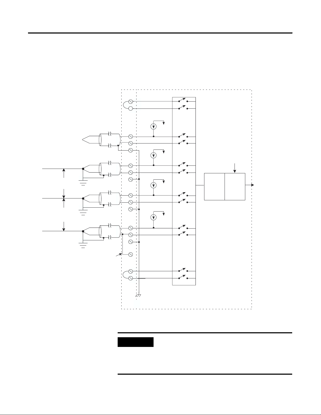
Input Circuit Block Diagram
Input Circuit Block Diagram
Terminal Block Module Circuitry
+
CJCA
Sensor
Open Circuit
Detection
within
2V*
within
2V*
*See Important note below.
Channel 0
Channel
Channel
Channel
ungrounded
thermocouple
1
grounded
thermocouple
2
grounded
thermocouple
3
grounded
thermocouple
user supplied
jumper
CJCB Sensor
+
-
Shield
+
+
-
-
Shield
+
-
Shield
+
-
Shield
Analog
Common
+
-
Multiplexer
Analog to
Digital
Convertor
User-Selected
Filter Frequency
Digital
Filter
Digital
Value
Publication 1746-UM007C-EN-P - July 2004
Chassis Ground
(internally connected)
IMPORTANT
When using multiple grounded and/or exposed
thermocouples that are touching on electrically
conductive material with Series B or higher
1746-NT4, the ground potential between any two
channels cannot exceed 2 volts.
Page 19
Overview 1-7
ATTENTION
The possibility exists that grounded or exposed
thermocouples can become shorted to a potential
greater than that of the thermocouple itself. Due to
possible shock hazard, care should be taken when
wiring these types of thermocouples. Refer to
Appendix D for more details.
Linear Millivolt Device Compatibility
A large number of millivolt devices may be used with the 1746-NT4
module. For this reason we do not specify compatibility with any
particular device.
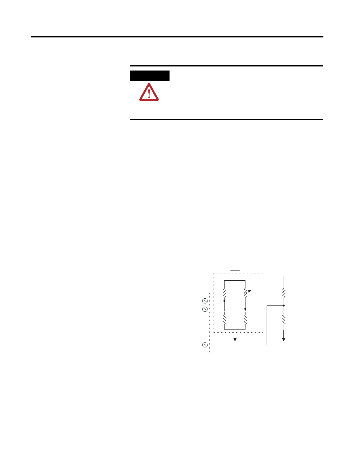
However, millivolt applications often use bridges of strain gages. To
allow the NT4 Series B (or higher) to operate correctly, the analog
common (
level within 2V of the signal of interest. A resistive voltage divider
using 10k Ω resistors is recommended to accomplish this. The circuit
diagram below shows how this connection is made.
ANALOG COM) terminal of the module needs to be biased to a
NT4
INPUT
(CHL0, CHL1,
CHL2, CHL3)
ANALOG COM
Strain
Gage
Bridge
fixed
+
-
fixed
+
Vcc
variable
fixed
10k Ω
10k
Ω
Publication 1746-UM007C-EN-P - July 2004
Page 20

1-8 Overview
Publication 1746-UM007C-EN-P - July 2004
Page 21

Chapter
2
Quick Start for Experienced Users
This chapter can help you to get started using the NT4 4-channel
thermocouple/mV module. The procedures are based on the
assumption that you have an understanding of SLC 500 products. You
should understand electronic process control and be able to interpret
the ladder logic instructions required to generate the electronic signals
that control your application.
Because it is a start-up guide for experienced users, this chapter does
not contain detailed explanations about the procedures listed. It does,
however, reference other chapters in this book where you can get
more information about applying the procedures described in each
step. It also references other documentation that may be helpful if you
are unfamiliar with programming techniques or system installation
requirements.
Required Tools and Equipment
If you have any questions or are unfamiliar with the terms used or
concepts presented in the procedural steps, always read the
referenced chapters and other recommended documentation before
trying to apply the information.
This chapter includes:
• Required Tools and Equipment
• Installation Procedures
Have the following tools and equipment ready:
• medium blade screwdriver
• medium cross-head screwdriver
• thermocouple or millivolt sensor
• appropriate thermocouple extension wire (if needed)
• 4-channel thermocouple/mV input module (1746-NT4)
• programming equipment
1 Publication 1746-UM007C-EN-P - July 2004
Page 22

2-2 Quick Start for Experienced Users
Installation Procedures
1. Check the contents of shipping box. Reference
Unpack the shipping box making sure that the contents include:
• thermocouple input module (Catalog Number 1746-NT4)
• removeable terminal block (factory installed on module) with CJC sensors attached.
• installation instructions (publication 1746-IN010)
If the contents are incomplete, call your local Allen-Bradley representative for assistance.
2. Ensure your chassis supports placement of the 1746-NT4 module Reference
Review the power requirements of your system to see that your chassis supports placement of the
thermocouple input module.
• For modular style systems, calculate the total load on the system power supply using the
procedure described in the SLC 500 Modular Hardware Style User Manual (Publication
Number 1747-UM011) or the SLC 500 Modular Chassis and Power Supplies Technical Data
(Publication Number 1746-TD003).
• The fixed, 2-slot chassis supports 2 thermocouple input modules. If combining a
thermocouple module with a different module, refer to the module compatibility table
found in chapter 3.
Chapter 3
(Installion and
Wiring
Appendix A
(Specifications)
Publication 1746-UM007C-EN-P - July 2004
Page 23
Quick Start for Experienced Users 2-3
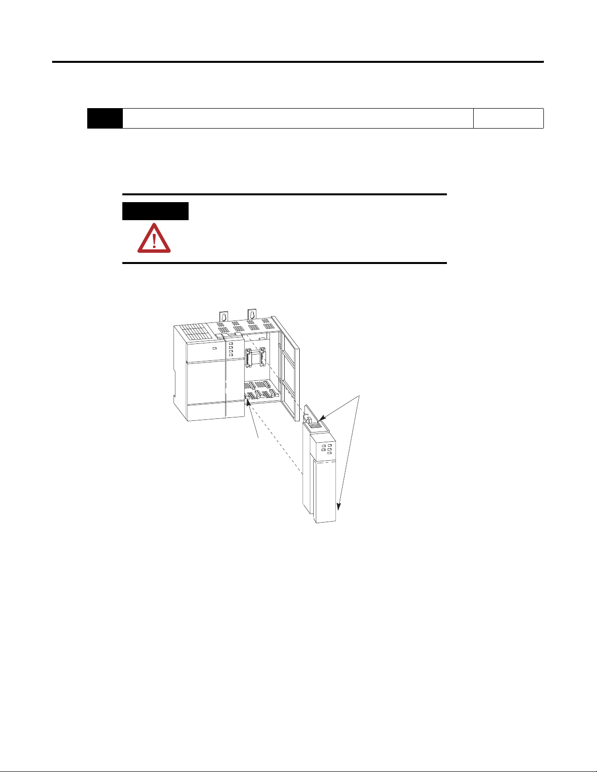
3. Insert the 1746-NT4 module into the chassis Reference
Make sure system power is off; then insert the thermocouple input module into your 1746
chassis. In this example procedure, local slot 1 is selected.
ATTENTION
Never install, remove, or wire modules with power
applied to the chassis or devices wired to the
module.
T
op and Bottom
Module Release(s)
Chapter 3
(Installation and
Wiring)
Card
Guide
Publication 1746-UM007C-EN-P - July 2004
Page 24
2-4 Quick Start for Experienced Users
4. Connect the thermocouple wires Reference
Connect thermocouple wires to channel 0 on the module’s terminal block. Make sure both cold
junction compensation (CJC) assemblies are securely attached.
Ground the shield drain wire at one end only. The preferred location is to the same point as the
sensor ground reference. For grounded thermocouples or mV sensors, this is at the sensor. For
insulated/ungrounded thermocouples, this is at the NT4 module.
Terminal
Block
CJC A
Assembly
SHIELD
SHIELD
CHL 0+
_
CHL
0
CHL 1+
_
CHL
1
Refer to the paragraph above
Thermocouple
Wire
Chapter 3
(Installion and
Wiring
Appendix D
(Thermocouple
Types
5. Configure the system. Reference
Configure your system I/O configuration for the particular slot the NT4 is in (slot 1 in this
example). Select the module from the drop-down list or enter the thermocouple input module ID
code (3510).
Chapter 4
(Preliminary
Operating
Considerations)
When using RSLogix 500 version 6.10 or higher, you may select Advanced Configuration, then
Configure, to use the software’s I/O wizard to configure the NT4 (see appendix E for details). If
you use this option, proceed to step 8.
Your
programming
software online
help screens
Publication 1746-UM007C-EN-P - July 2004
Page 25
Quick Start for Experienced Users 2-5
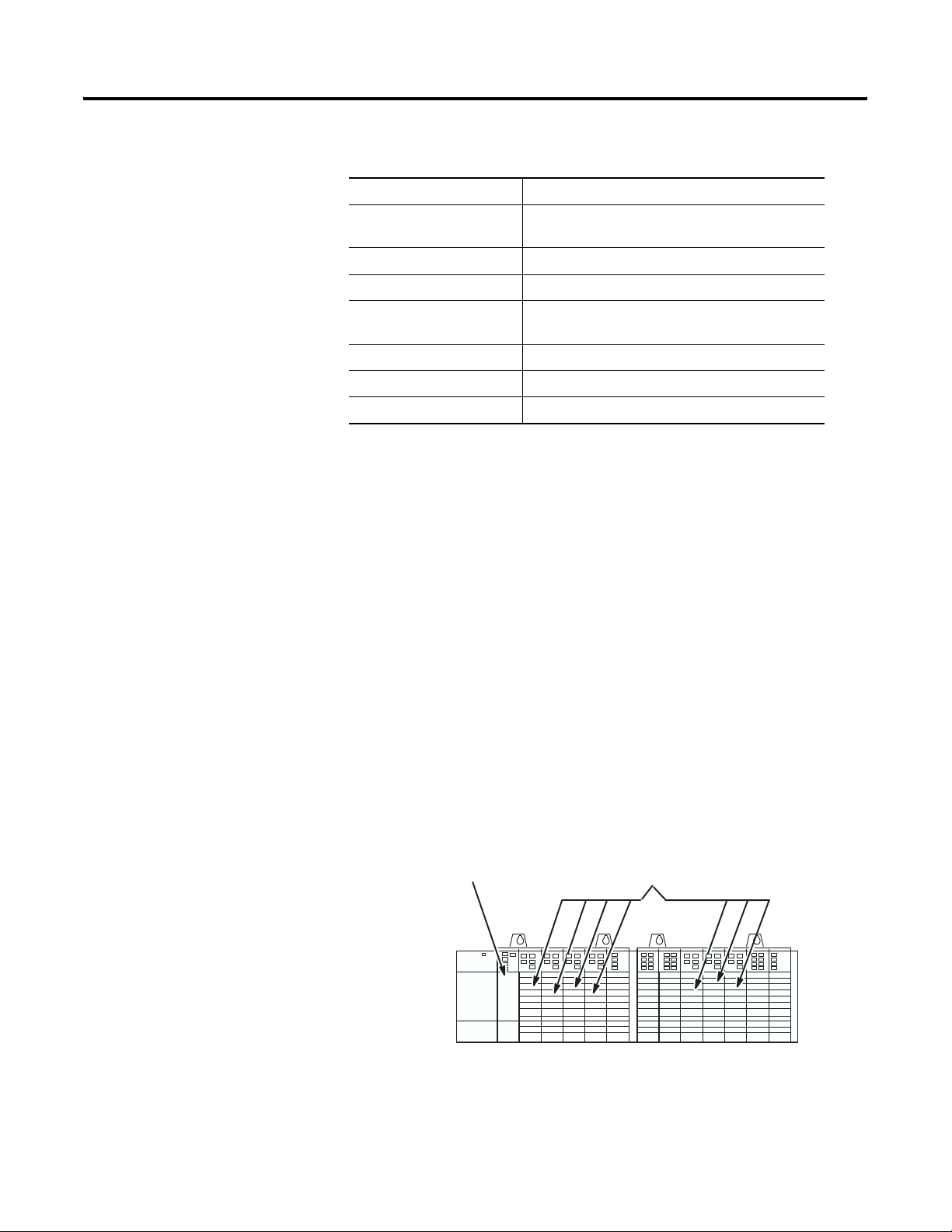
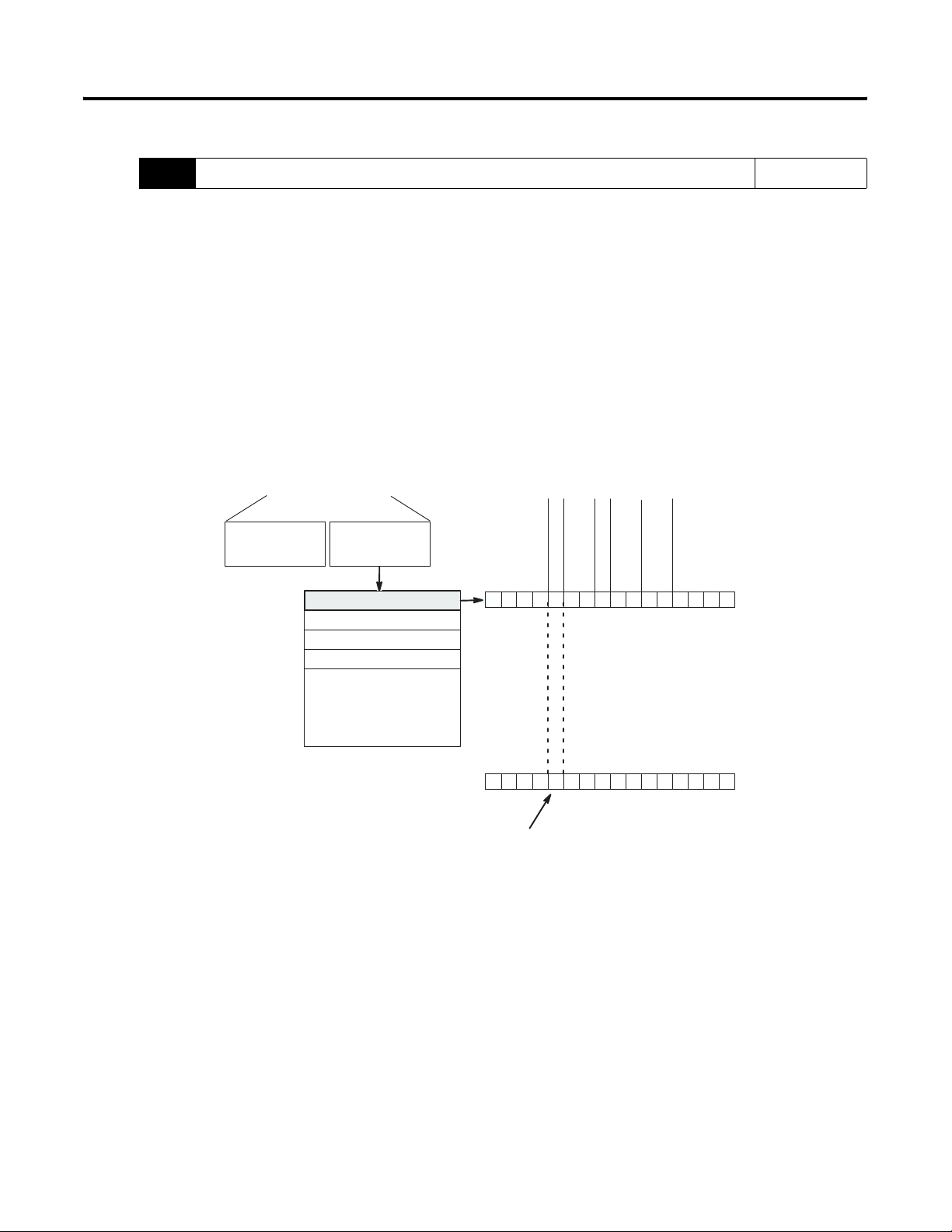
6. Determine the operating parameters. Reference
Determine the operating parameters for channel 0. This example shows the channel 0
configuration word defined with all defaults (0) except for channel enable (bit 11). The
addressing reflects the location of the module as slot 1.
SLC 500 Controller
Data Files
Output Image
(8 words)
Channel 0 Configuration Word
Channel 1 Configuration W
Channel 2 Configuration W
Channel 3 Configuration W
W
ords 4 7
(not defined)
ord
ord
ord
_
Unused
emperature Units
Filter Frequency
Channel Enable
T
Data Format
Open Circuit
000000000000000
Default Setting
Type J Thermocouple
•
Engineering Units x 1
•
Data Word = 0 If Open Circuit
•
Degrees Celsius
•
10 Hz. Filter Frequency
•
Channel Disabled
•
Bit
15
000010000000000
New Setting
Address
O:1.0
O:1.1
O:1.2
O:1.3
•
•
•
O:1.7
Input Image
W
ord 0
W
ord 1
W
ord 2
W
ord 3
•
•
•
W
ord 7
Chapter 4
(Preliminary
Operating
Considerations)
Chapter 5
(Channel
Configuration,
Data, and
Status)
Appendix B
(NT4
Configuration
Worksheet)
Type
Input
0
Bit 0
0
Set this bit (11) to enable channel. Address = O:1.0/11.
Publication 1746-UM007C-EN-P - July 2004
Page 26
2-6 Quick Start for Experienced Users
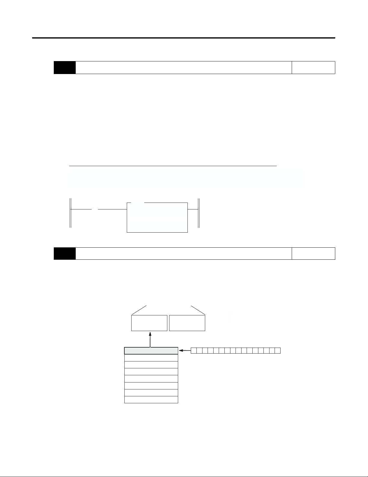
7.
Program the configuration.
Do the programming necessary to establish the new configuration word setting in the previous
step.
1. Create integer file N10. Integer file N10 should contain one element for each channel used.
(For this example we only need one, N10:0.)
2. Enter the configuration parameters from step 6 for channel 0 into integer N10:0.
In this example all the bits of N10:0 will be zero except for the channel enable (N10:0/11).
3. Program an instruction in your ladder logic to copy the contents of N10:0 to output word O:1.0.
Example of Data Table for Integer File N10:
address
N10:0 0000 1000 0000 0000
15 data 0 address 15 data 0
First Pass Bit
S:1
] [
15
COP
COPY FILE
Source
# N10:0
Dest #
Length 1
O:1.0
On power up, the first pass bit
(S:1/15) is set for one scan, enabling
the COPY instruction that transfers a
one to bit 11 of channel configuration
word 0. This enables the channel..
Reference
Chapter 6
(Ladder
Programming
Examples)
Chapter 8
(Application
Examples)
8. Write the ladder program. Reference
Write the remainder of the ladder logic program that specifies how your thermocouple input data
will be processed for your application. In this procedure the addressing reflects the location of
the module as slot 1.
Chapter 5
(Channel
Configuration,
Data, and
Status)
Chapter 6
(Ladder
Programming
Examples)
Chapter 8
(Application
Examples)
Your
programming
device user
manual.
Address
I:1.0
I:1.1
I:1.2
I:1.3
•
•
•
I:1.7
W
W
W
W
W
ord 0
ord 1
ord 2
ord 3
•
•
•
ord 7
SLC 500 Controller
Data Files
Input Image
(8 words)
Channel 0 Data W
Channel 1 Data W
Channel 2 Data W
Channel 3 Data W
Channel 0 Status W
Channel 1 Status W
Channel 2 Status W
Channel 3 Status W
ord
ord
ord
ord
ord
ord
ord
ord
Output Image
Address
I:1.0
000000000000000
(V
ariable
Bit
15
Thermocouple Input Data)
0
Bit 0
Publication 1746-UM007C-EN-P - July 2004
Page 27
Quick Start for Experienced Users 2-7
9. Go through the system start-up proceedure. Reference
Apply power. Download your program to the SLC and put the controller into Run mode. In this
example during a normal start up, the module status LED and channel status 0 LED turn on.
Chapter 7
(Module
Diagnostics and
Troubleshooting)
INPUT
CHANNEL
STATUS
MODULE STATUS
THERMOCOUPLE/mV
012
3
Channel LEDs
Module Status LED
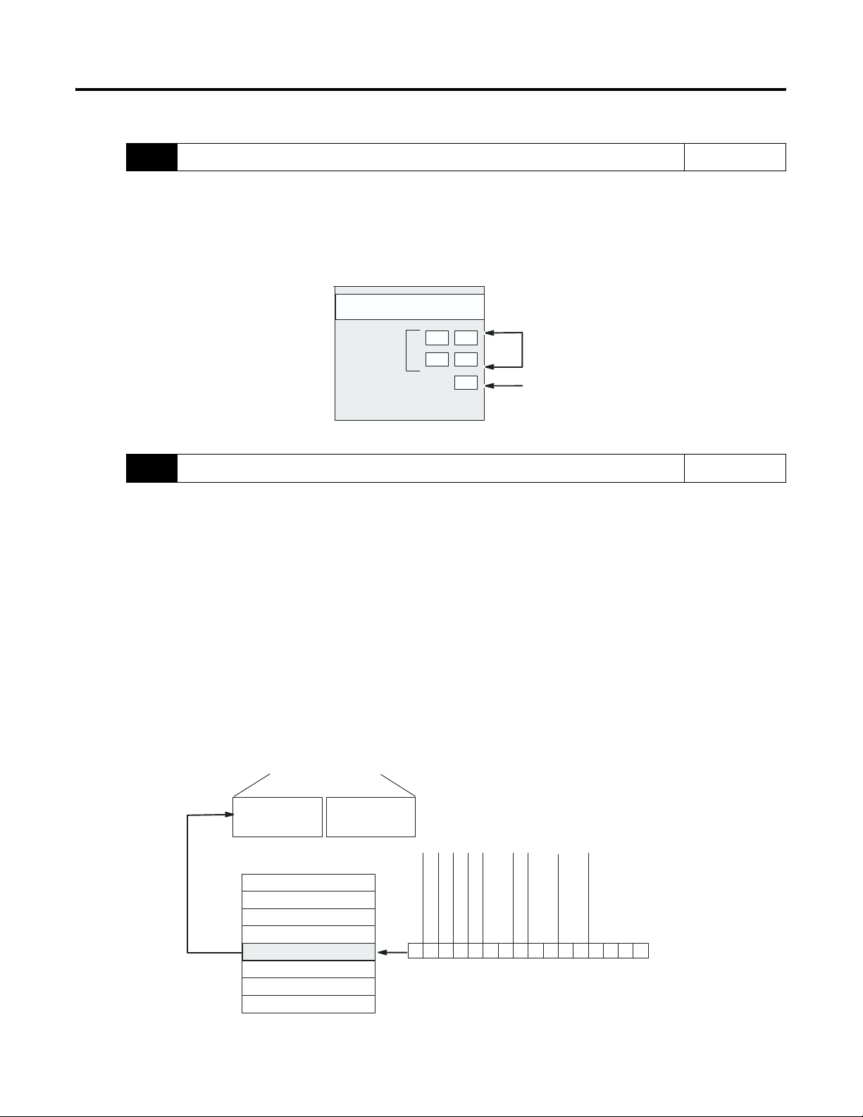
10. Check module operation. Reference
(Optional) Monitor the status of input channel 0 to determine its configuration setting and
operational status. This is useful for troubleshooting when the blinking channel LED indicates
that an error has occurred. If the Module Status LED is off, or if the Channel 0 LED is off or
blinking, refer to chapter 7.
Chapter 5
(Channel
Configuration,
Data, and
Status)
Chapter 6
(Ladder
Programming
Examples)
W
W
W
W
ord 0
ord 1
ord 2
ord 3
•
•
ord 7
SLC 500 Controller
Data Files
Input Image
(8 words)
Channel 0 Data W
Channel 1 Data W
Channel 2 Data W
Channel 3 Data W
Channel 0 Status W
Channel 1 Status W
Channel 2 Status W
Channel 3 Status W
Output Image
ordW
ord
ord
ord
ord
ord
ord
ord
Type
Type
Open Circuit Error
Channel Status
Under Range Error
Configuration Error
Over Range Error
000010000000000
Bit
15
emperature Units
Filter Frequency
T
Address
Open Circuit
Data Format
Input
0
Bit 0
I:1.4
For this example, during normal operation only bit 11 is set.
Publication 1746-UM007C-EN-P - July 2004
Chapter 8
(Application
Examples)
Page 28

2-8 Quick Start for Experienced Users
Publication 1746-UM007C-EN-P - July 2004
Page 29

Installation and Wiring
This chapter provides:
• Compliance to European Union Directives
• Electrostatic Discharge
• NT4 Power Requirements
• Module Location in Chassis
• Module Installation and Removal
• Terminal Wiring
• Thermocouple Calibration
Chapter
3
Compliance to European Union Directives
If this product has the CE mark it is approved for installation within
the European Union and EEA regions. It has been designed and tested
to meet the following directives.
EMC Directive
The Series B (or higher) 1746-NT4 is tested to meet Council Directive
89/336/EEC Electromagnetic Compatibility (EMC) and the following
standards, in whole or in part, documented in a technical construction
file:
• EN 50081-2
EMC - Generic Emission Standard, Part 2 - Industrial
Environment
• EN 50082-2
EMC - Generic Immunity Standard, Part 2 - Industrial
Environment
This product is intended for use in an industrial environment.
1 Publication 1746-UM007C-EN-P - July 2004
Page 30

3-2 Installation and Wiring
Electrostatic Discharge
Electrostatic discharge can damage semiconductor devices inside this
module if you touch backplane connector pins. Guard against
electrostatic damage by observing the precautions listed next.
ATTENTION
•
Wear an approved wrist strap grounding device when handling
the module.
Touch a grounded object to rid yourself of electrostatic charge
•
before handling the module.
Handle the module from the front, away from the backplane
•
connector. Do not touch backplane connector pins.
Keep the module in its static-shield bag when not in use, or
•
during shipment.
Electrostatic discharge can degrade performance or
cause permanent damage. Handle the module as
stated below.
NT4 Power Requirements
The thermocouple module receives its power through the SLC500
chassis backplane from the fixed or modular +5 VDC/+24 VDC chassis
power supply. The maximum current drawn by the module is shown
in the table below.
5V dc Amps 24V dc Amps
0.06 0.04
When you are using a modular system configuration, add the values
shown in the table above to the requirements of all other modules in
the SLC chassis to prevent overloading the chassis power supply.
When you are using a fixed system controller, refer to the important
note about module compatibility in a 2-slot expansion chassis on page
3-3.
Publication 1746-UM007C-EN-P - July 2004
Page 31

Installation and Wiring 3-3
Module Location in Chassis
Place your thermocouple module in any slot of an SLC 500 modular,
or modular expansion chassis, except for the extreme left slot (slot 0)
in the first chassis. This slot is reserved for the processor or adapter.
Fixed Expansion Chassis Considerations
IMPORTANT
In the table:
• AN "x" indicates a valid combination.
• No symbol indicates an invalid combination.
• A "+" indicates an external power supply (refer to the SLC 500
4-Channel Analog I/O Modules User Manual, publication
1746-UM005 for more information).
The 2-slot, SLC 500 fixed I/O expansion chassis
(1746-A2) will support only specific combinations of
modules. If you are using the thermocouple module
in a 2-slot expansion chassis with another SLC I/O or
communication module, refer to the table starting
below to determine whether the combination can be
supported.
When using the table, be aware that there are certain conditions that
affect the compatibility characteristics of the BASIC module (BAS) and
the DH-485/RS-232C module (KE).
When you use the BAS module or the KE module to supply power to
a 1747-AIC Link Coupler, the Link Coupler draws its power through
the module. The higher current drawn by the AIC at 24 VDC is
calculated and recorded in the table for the modules identified as
BASn (BAS networked) or KEn (KE networked). Make sure to refer to
these modules if your application uses the BAS or KE module in this
way.
1746- NT4 5V dc Amps 24V dc Amps
IA4 x 0.035 N/A
IA8 x 0.050 N/A
IA16 x 0.085 N/A
IM4 x 0.035 N/A
IM8 x 0.050 N/A
Publication 1746-UM007C-EN-P - July 2004
Page 32

3-4 Installation and Wiring
1746- NT4 5V dc Amps 24V dc Amps
IM16 x 0.085 N/A
OA8 x 0.185 N/A
OA16 x 0.370 N/A
OAP12 x 0.370 N/A
IB8 x 0.050 N/A
IB16 x 0.085 N/A
IV8 x 0.050 N/A
IV16 x 0.085 N/A
IG16 x 0.140 N/A
OV8 x 0.135 N/A
OV16 x 0.270 N/A
OB8 x 0.135 N/A
OBP8 x 0.135 N/A
OG16 x 0.180 N/A
OW4 x 0.045 0.045
OW8 x 0.085 0.090
OW16 0.170 0.180
IO4 x 0.030 0.025
IO8 x 0.060 0.045
IO12 x 0.090 0.070
NI4 x 0.025 0.085
NIO4I x 0.055 0.145
NIO4IV x 0.055 0.115
FIO4I x 0.055 0.150
FIO4V x 0.055 0.120
DCM x 0.360 N/A
HS x 0.300 N/A
OB16 x 0.28 N/A
IN16 x 0.085 N/A
BASn x 0.150 0.125
BAS x 0.150 0.040
OB32 0.452 N/A
Publication 1746-UM007C-EN-P - July 2004
OV32 0.452 N/A
IV32 x 0.106 N/A
IB32 x 0.106 N/A
OX8 x 0.085 0.090
NO4I + 0.055 0.195
Page 33

Installation and Wiring 3-5
1746- NT4 5V dc Amps 24V dc Amps
NO4V x 0.055 0.145
ITB16 x 0.085 N/A
ITV16 x 0.085 N/A
IC16 x 0.085 N/A
KE x 0.150 0.040
KEn x 0.150 0.145
OBP16 x 0.250 N/A
OVP16 x 0.250 N/A
NT4 x 0.060 0.040
NR4 x 0.050 0.050
HSTP1 x 0.020 N/A
General Considerations
Module Installation and Removal
Most applications require installation in an industrial enclosure to
reduce the effects of electrical interference. Thermocouple inputs are
highly susceptible to electrical noises due to the small amplitudes of
their signal (microvolt/°C).
Group your modules to minimize adverse effects from radiated
electrical noise and heat. Consider the following conditions when
selecting a slot for the thermocouple module. Position the module:
• in a slot away from sources of electrical noise such as
hard-contact switches, relays, and AC motor drives
• away from modules which generate significant radiated heat,
such as the 32-point I/O modules
In addition, route shielded twisted pair thermocouple or millivolt
input wiring away from any high voltage I/O wiring.
When installing the module in a chassis, it is not necessary to remove
the terminal block from the module. However, if the terminal block is
removed, use the write-on label located on the side of the terminal
block to identify the module location and type.
SLOT ____ RACK ____
• MODULE
_______________
Publication 1746-UM007C-EN-P - July 2004
Page 34

3-6 Installation and Wiring
Terminal Block Removal
ATTENTION
Never install, remove, or wire modules with power
applied to the chassis or devices wired to the
module.
To remove the terminal block:
1. Loosen the two terminal block release screws.
2. Grasp the terminal block at the top and bottom and pull
outward and down. When removing or installing the terminal
block be careful not to damage the CJC sensors.
CJC Sensors
Terminal
Block Release
Screws
Publication 1746-UM007C-EN-P - July 2004
Module Installation Procedure
1. Align the circuit board of the thermocouple module with the
card guides located at the top and bottom of the chassis.
2. Slide the module into the chassis until both top and bottom
retaining clips are secured. Apply firm even pressure on the
module to attach it to its backplane connector. Never force the
module into the slot.
Page 35

Installation and Wiring 3-7
3. Cover all unused slots with the Card Slot Filler, Catalog Number
1746-N2.
Top and Bottom
Module Release(s)
Card Guide
Terminal Wiring
Module Removal Procedure
1. Press the releases at the top and bottom of the module and slide
the module out of the chassis slot.
2. Cover all unused slots with the Card Slot Filler, Catalog Number
1746-N2.
The thermocouple module contains a green, 18-position, removable
terminal block. The terminal pin-out is shown on page 3-8.
ATTENTION
Disconnect Power to the SLC before attempting to
install, remove, or wire the removable terminal
wiring block.
To avoid cracking the removable terminal block,
alternate the removal of the slotted terminal block
release screws.
Publication 1746-UM007C-EN-P - July 2004
Page 36

3-8 Installation and Wiring
(Terminal Block Spare Part Catalog Number 1746-RT32)
Release Screw
Channel 0+
Channel 0
Channel 1+
Channel 1
Channel 2+
Channel 2
Channel 3+
Channel 3
Analog Common
[see below]
_
_
_
_
CJC Assembly
Shield
Shield
Shield
Shield
Shield
CJC Assembly
Release Screw
CJC A+
CJC A
CJC B
CJC B+
_
_
Replacing a Series A thermocouple module with a Series B module
requires that the bottom right terminal (which was SHIELD on Series A
modules) no longer be connected to CHASSIS GROUND if it was
previously. Use one of the other SHIELD terminals.
Wiring Considerations
ATTENTION
Follow the guidelines starting below when planning your system
wiring.
• To limit noise, keep thermocouple and millivolt signal wires as
far away as possible from power and load lines.
The possibility exists that grounded or exposed
thermocouples can become shorted to a potential
greater than that of the thermocouple itself. Due to
possible shock hazard, care should be taken when
wiring these types of thermocouples. Refer to
Appendix D for more details.
Publication 1746-UM007C-EN-P - July 2004
Page 37

Installation and Wiring 3-9
• To ensure proper operation and high immunity to electrical
noise, always use Belden
™ 8761 (shielded, twisted pair) or
equivalent wire for millivolt sensors or shielded, twisted pair
thermocouple extension lead wire specified by the
thermocouple manufacturer for the thermocouple type you are
using. Using the incorrect thermocouple extension wire type or
not following the correct polarity convention will cause invalid
readings.
• Special considerations for using the analog common
(
ANALOG COM) terminal based on thermocouple type:
(See Appendix D for definitions of thermocouple types.)
– When using grounded thermocouple(s), jumper the
COM terminal to any single active grounded channel’s plus (+)
ANALOG
or minus (-) terminal.
– When using exposed thermocouple(s) that have the
thermocouple junction touching an electrically conductive
material, jumper the
ANALOG COM terminal to any single active
exposed channel’s plus (+) or minus (-) terminal.
– When using ungrounded (shielded) or exposed
thermocouples that are not touching an electrically
conductive material, do not use the
ANALOG COM terminal.
– When using a mix of grounded, ungrounded and exposed
thermocouples, jumper the
ANALOG COM terminal to any
single active grounded channel’s plus (+) or minus (-)
terminal.
If millivolt inputs are used, the terminal should be handled as
–
discussed on page 1-7.
The Series A 1746-NT4 does not have an
ANALOG COM
terminal and cannot be used with multiple grounded and/or
exposed thermocouples that touch electrically conductive
material. The Series A can be used with a single grounded
and/or exposed thermocouple that touches electrically
conductive material, or multiple grounded thermocouples that
have the protective sheath made of an electrically
non-conductive material such as ceramic.
• Ground the shield drain wire at one end only. The preferred
location is to the same point as the sensor ground reference.
– For grounded thermocouples or mV sensors, this is at the
sensor.
– For insulated/ungrounded thermocouples, this is at the
module.
– (Refer to IEEE Std. 518, Section 6.4.2.7 or contact your sensor
manufacturer for additional details.)
Publication 1746-UM007C-EN-P - July 2004
Page 38

3-10 Installation and Wiring
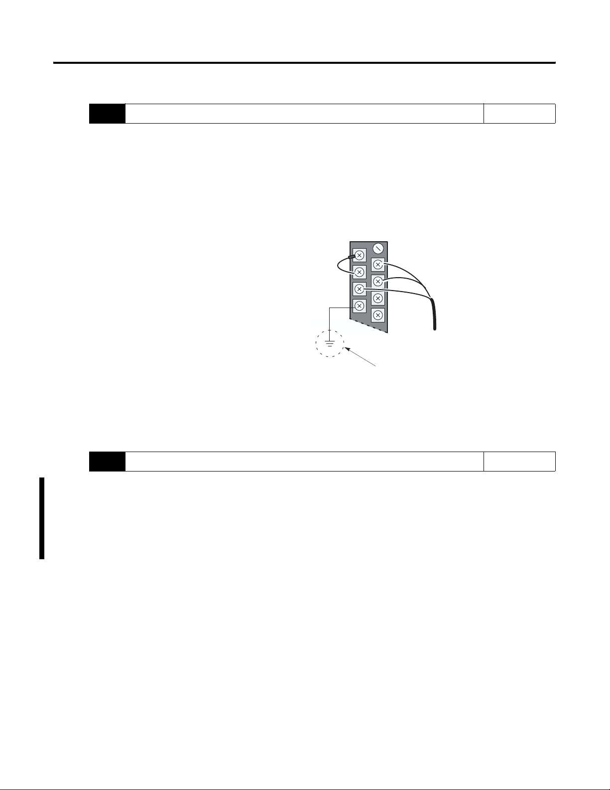
• If it is necessary to connect the shield at the module, each input
channel has a convenient shield connection screw terminal that
provides a connection to chassis ground. All shields are
internally connected, so any shield terminal can be used with
channels 0-3. For maximum noise reduction, one shield terminal
must be connected to earth ground potential, i.e. mounting bolt
on 1746 chassis.
• Tighten terminal screws using a flat or cross-head screwdriver.
Each screw should be turned tight enough to immobilize the
wire’s end. Excessive tightening can strip the terminal screw.
The torque applied to each screw should not exceed 5 lb-in
(0.565 Nm) for each terminal.
• The open thermocouple detection circuit injects approximately
12 nanoamperes into the thermocouple cable. A total lead
resistance of 25 ohms (12.5 one-way) will produce 0.3 mV of
error. To reduce error, use large gage wire with less resistance
for long wire runs.
• Follow system grounding and wiring guidelines found in your
SLC 500 Modular Hardware Style User Manual (publication
1747-UM011).
Publication 1746-UM007C-EN-P - July 2004
Page 39

Installation and Wiring 3-11
)
Wiring Input Devices to the NT4
After the thermocouple module is properly installed in the chassis,
follow the wiring procedure below using the proper thermocouple
extension cable, or Belden 8761 for non-thermocouple applications.
Signal Wire
Signal Wire
Cable
Foil ShieldDrain Wire
(Twist together, shrink wrap,
and connect to earth ground.)
Signal Wire
(Cut foil shield and
drain wire; then
insulate at cable end.
Signal Wire
To wire your NT4 module:
1. At each end of the cable, strip some casing to expose the
individual wires.
2. Trim the signal wires to 2-inch lengths. Strip about 3/16 inch
(4.76 mm) of insulation away to expose the end of the wire.
3. At one end of the cable twist the drain wire and foil shield
together, bend them away from the cable, and apply shrink
wrap. Then earth ground at the preferred location based on the
type of sensor you are using (see Wiring Considerations).
4. At the other end of the cable, cut the drain wire and foil shield
back to the cable and apply shrink wrap.
5. Connect the signal wires to the NT4 terminal block and the
input.
6. Repeat steps 1 through 6 for each channel on the NT4 module.
Publication 1746-UM007C-EN-P - July 2004
Page 40

3-12 Installation and Wiring
Cold Junction Compensation (CJC)
ATTENTION
Do not remove or loosen the cold junction
compensating thermistor assemblies located between
the two upper and lower CJC terminals on the
terminal block. Both thermistor assemblies are
critical to ensure accurate thermocouple input
readings at each channel. The module will not
operate in the thermocouple mode if either assembly
is removed.
To obtain accurate readings from each of the channels, the cold
junction temperature (temperature at the module’s terminal junction
between the thermocouple wire and the input channel) must be
compensated for. Two cold junction compensating thermistors have
been integrated in the removable terminal block; they must remain
installed to retain accuracy.
In case of accidental removal of either or both of the thermistor
assemblies, make sure to replace them by connecting each one across
the CJC terminals located at the top and bottom left side of the
terminal block. When connecting the thermistor assembly at the top of
the terminal block (between terminals CJC A+ and CJC A-), the lug
containing the thermistor (marked with red epoxy) should attach to
the uppermost screw terminal (CJC A+). When connecting the
thermistor assembly at the bottom of the terminal block (between
terminals CJC B+ and CJC B-), the lug containing the thermistor
should attach to the lowermost screw terminal (CJC B+).
Publication 1746-UM007C-EN-P - July 2004
CJC Assembly
Thermistor
(Always attach red lug to the
CJC+ terminal.)
Bottom of Terminal Block
Page 41

Installation and Wiring 3-13
Thermocouple Calibration
The thermocouple module is initially calibrated at the factory. The
module also has an auto calibration function. Auto calibration
compensates for offset and gain drift of the A/D converter caused by
temperature change within the module. An internal, high precision,
low drift voltage and system ground reference is used for this
purpose. No external, user supplied device is required for
autocalibration.
When an auto calibration cycle takes place, the module’s multiplexer
is set to system ground potential and an A/D reading is taken. The
A/D converter then sets its internal input to the modules precision
voltage source, and another reading is taken. The A/D converter uses
these numbers to compensate for “system” offset (zero) and gain
(span) error.
Autocalibration of a channel occurs whenever a channel is enabled, or
when a change is made to its input type or filter frequency. You can
also command your module to perform an autocalibration cycle by
disabling a channel, waiting for the status bit to change state (1 to 0)
and then re-enabling that channel. Several channel cycles are required
to perform an autocalibration, and it is important to remember that
during autocalibration the module is not converting input data.
To maintain system accuracy we recommend that you periodically
perform an autocalibration cycle, for example:
• whenever an event occurs that greatly changes the internal
temperature of the control cabinet, such as opening or closing
its door
• at a convenient time when the system is not making product,
such as during a shift change
An autocalibration programming example is provided in chapter 6.
Accuracy specifications with and without autocalibration are provided
in Appendix A.
Publication 1746-UM007C-EN-P - July 2004
Page 42

3-14 Installation and Wiring
Publication 1746-UM007C-EN-P - July 2004
Page 43

Chapter
4
Preliminary Operating Considerations
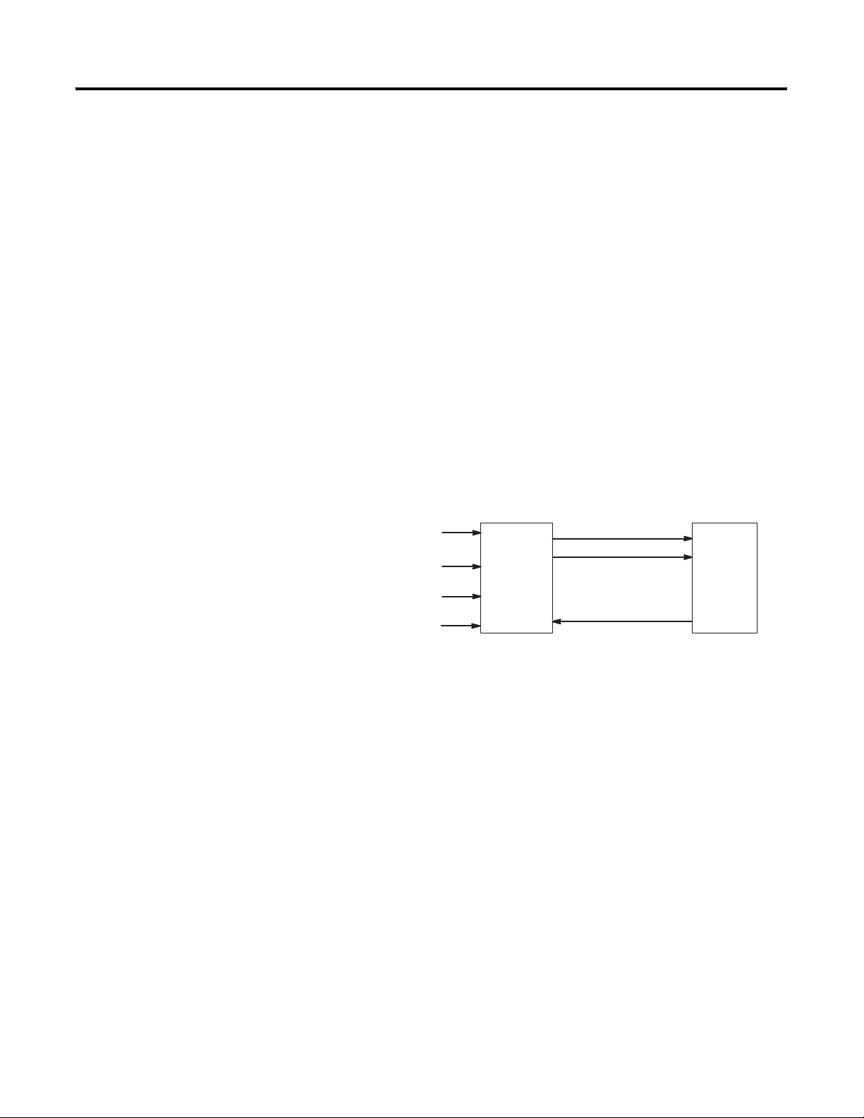
This chapter explains how the thermocouple module and the SLC
processor communicate through the module’s input and output image.
It lists the preliminary setup and operation required before the
thermocouple module can function in a 1746 I/O system. Topics
include:
• Module ID Code
• Module Addressing
• Channel Filter Frequency Selection
• Update Time
• Channel Turn-On, Turn-Off, and Reconfiguration Times
• Response to Slot Disabling
Module ID Code
The module identification code is a unique number encoded for each
1746 I/O module. The code defines for the processor the type of I/O
or specialty module residing in a specific slot in the 1746 chassis.
The module ID code for the thermocouple module is shown below:
Catalog Number ID Code
1746-NT4 3510
No special I/O configuration information is required. The module ID
code automatically assigns the correct number of input and output
words.
1 Publication 1746-UM007C-EN-P - July 2004
Page 44

4-2 Preliminary Operating Considerations
Module Addressing
SLC 5/0X
Data Files
Slot e
Output Image
Slot e
Input Image
Output
Scan
Input
Scan
The following memory map shows you how the output and input
image tables are defined for the thermocouple module.
Bit
Thermocouple
Module
Image Table
Output Image
8 W
ords
Input Image
8 W
ords
(Class 1)
Output Image
Input Image
15
Channel 0 Configuration W
Channel 1 Configuration W
Channel 2 Configuration W
Channel 3 Configuration W
Channel 0 Data W
Channel 1 Data W
Channel 2 Data W
Channel 3 Data W
Channel 0 Status W
Channel 1 Status W
Channel 2 Status W
Channel 3 Status W
Bit 15
_
W
ords 4 7
(not defined)
ord
ord
ord
ord
ord
ord
ord
ord
ord
ord
ord
ord
Bit 0
Bit 0
W
W
W
W
W
W
W
W
W
W
W
W
W
ord 0
ord 1
ord 2
ord 3
•
•
•
ord 7
ord 0
ord 1
ord 2
ord 3
ord 4
ord 5
ord 6
ord 7
Address
O:e.0
O:e.1
O:e.2
O:e.3
•
•
•
O:e.7
Address
I:e.0
I:e.1
I:e.2
I:e.3
I:e.4
I:e.5
I:e.6
I:e.7
Output Image-Configuration Words
The 8-word, thermocouple module output image (defined as the
output from the CPU to the thermocouple module) contains
information that you configure to define the way a specific channel on
the thermocouple module will work. These words take the place of
configuration DIP switches on the module. Although the
thermocouple output image is eight words long, only output words
0-3 are used to define the operation of the module; output words 4-7
are not used. Each output word configures a single channel.
Example - If you want to configure channel 2 on the thermocouple
module located in slot 4 in the chassis, your address would be O:4.2.
File Type
Element
Delimiter
O : 4 . 2
Slot
Word
Word
Delimiter
Publication 1746-UM007C-EN-P - July 2004
Page 45

Preliminary Operating Considerations 4-3
Chapter 5, Channel Configuration, Data, and Status, gives you
detailed bit information about the data content of the configuration
word.
Input Image-Data Words and Status Words
The 8-word, thermocouple module input image (defined as the input
from the thermocouple module to the CPU) represents data words
and status words.
Input words 0-3 (data words) hold the input data that represent the
temperature value of thermocouple analog inputs for channels 0-3.
This data word is valid only when the channel is enabled and there
are no channel errors.
Input words 4-7 (status words) contain the status of channels 0-3
respectively. The status bits for a particular channel reflect the
configuration settings that you have entered into the output image
configuration word for that channel and provide information about
the channel’s operational state. To receive valid status information the
channel must be enabled, and the channel must have processed any
configuration changes that may have been made to the configuration
word.
Example - To obtain the status of channel 2 (input word 6) of the
thermocouple module located in slot 4 in the SLC chassis, use address
I:4.6.
File Type
Slot
Word
I : 4 . 6
Element
Delimiter
Chapter 5, Channel Configuration, Data, and Status, gives you
detailed bit information about the content of the data word and the
status word.
Word
Delimiter
Publication 1746-UM007C-EN-P - July 2004
Page 46

4-4 Preliminary Operating Considerations
Channel Filter Frequency Selection
The thermocouple module uses a digital filter that provides high
frequency noise rejection for the input signals. The digital filter is
programmable, allowing you to select from four filter frequencies for
each channel. The digital filter provides the highest noise rejection at
the selected filter frequency.
Selecting a low value (i.e. 10 Hz) for the channel filter frequency
provides the best noise rejection for a channel, but it also increases
the channel update time. Selecting a high value for the channel filter
frequency provides lower noise rejection, but decreases the channel
update time.
The following table shows the available filter frequencies, associated
minimum normal mode rejection (NMR), cut-off frequency, and step
response for each filter frequency.
Filter
Frequency
10 Hz 100 dB 100 dB 2.62 Hz 300 msec
50 Hz 100 dB - 13.1 Hz 60 msec
60 Hz - 100 dB 15.72 Hz 50 msec
50Hz NMR 60Hz NMR Cut-Off
Frequency
Step
Response
250 Hz - - 65.5 Hz 12 msec
Effective Resolution
The effective resolution for an input channel depends upon the filter
frequency selected for that channel. Graphs that shows actual bit
resolution for the thermocouple types at all filter frequencies are
provided in Appendix A.
Publication 1746-UM007C-EN-P - July 2004
Page 47
Preliminary Operating Considerations 4-5
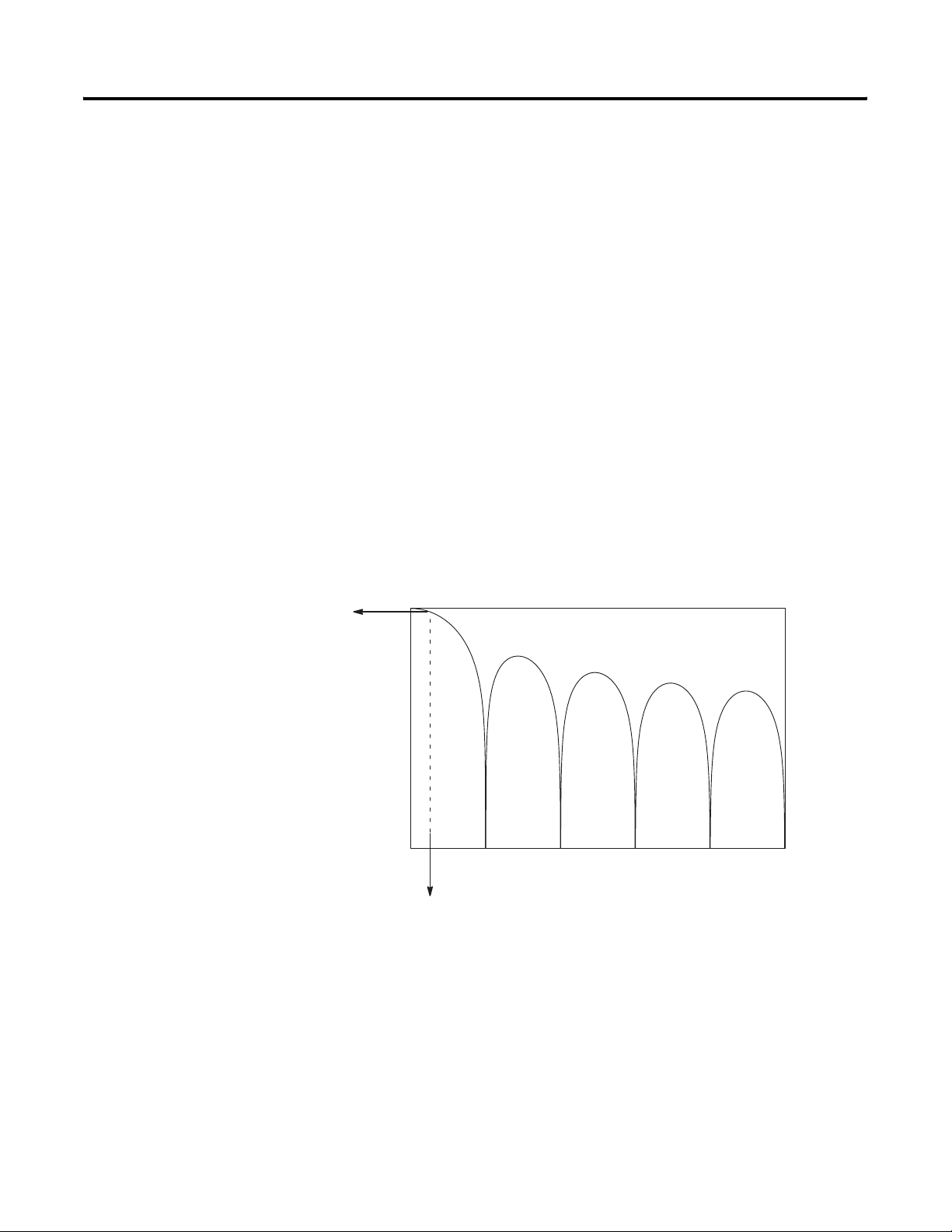
Channel Cut-Off Frequency
The channel filter frequency selection determines a channel’s cut-off
frequency, also called the -3 dB frequency. The cut-off frequency is
defined as the point on the input channel frequency response curve
where frequency components of the input signal are passed with 3 dB
of attenuation. All frequency components at or below the cut-off
frequency are passed by the digital filter with less than 3 dB of
attenuation. All frequency components above the cut-off frequency
are increasingly attenuated, as show in the graphs starting below.
The cut-off frequency for each input channel is defined by its filter
frequency selection. The table on the previous page lists the input
channel cut-off frequency for each filter frequency. Choose a filter
frequency so that your fastest changing signal is below that of the
filter’s cut-off frequency. The cut-off frequency should not be
confused with update time. The cut-off frequency relates how the
digital filter attenuates frequency components of the input signal. The
update time defines the rate at which an input channel is scanned and
its channel data word updated.
60 Hz Filter Notch Frequency
Frequency Response
Amplitude
-3 dB
(in dB)
0
_
20
_
40
_
60
_
80
_
100
_
120
_
140
_
160
_
180
_
200
0 60 120 180 240 300
15.72 Hz
Frequency
Hz
Publication 1746-UM007C-EN-P - July 2004
Page 48

4-6 Preliminary Operating Considerations
250 Hz Filter Notch Fre quency
Frequency Response
Amplitude
-3 dB
(in dB)
0
_
20
_
40
_
60
_
80
_
100
_
120
_
140
_
160
_
180
_
200
0 250 500 750 1000 1250 1500
65.5 Hz
Channel Step Response
Frequency
The channel filter frequency determines the channel’s step response.
The step response is time required for the analog input signal to reach
100% of its expected final value. This means that if an input signal
changes faster than the channel step response, a portion of that signal
will be attenuated by the channel filter. The table on page 4-4 shows
the step response for each filter frequency.
Publication 1746-UM007C-EN-P - July 2004
Page 49
Preliminary Operating Considerations 4-7
Update Time
The thermocouple module update time is defined as the time required
for the module to sample and convert the input signals of all enabled
input channels and make the resulting data values available to the SLC
processor. It can be calculated by adding the the sum of all enabled
channel sample times, plus a CJC update time.
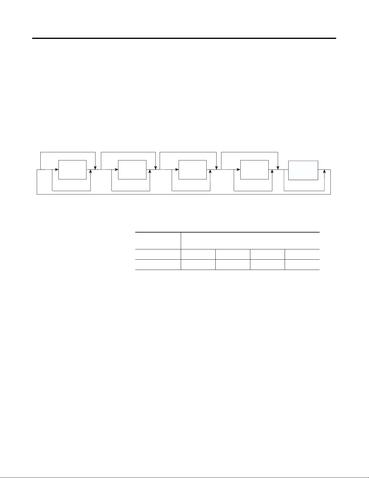
The NT4 module sequentially samples the channels in a continuous
loop.
Channel
0 Disabled
Enabled Enabled Enabled Enabled
Sample
Channel 0
Update
CJC
Channel 1 Disabled Channel 2 Disabled Channel 3 Disabled
Sample
Channel 1
Calculate Previous
Sample
Channel 2
Calculate Previous Calculate Previous Calculate Previous
The following table shows the channel sampling times for each filter
frequency. It also gives the CJC update time.
Sample
Channel 3
Sample
CJC
Channels
CJC Update
Channel Sampling Time
Tim e
250 Hz Filter 60 Hz Filter 50 Hz Filter 10 Hz Filter
14 msec 12 msec 50 msec 60 msec 300 msec
The fastest module update time occurs when only one channel with a
250 Hz filter frequency is enabled.
Module update time = 12 ms + 14 ms = 26 ms
The slowest module update time occurs when four channels, each
using a 10 Hz filter frequency (4 * 300 = 1200), are enabled.
Module update time = 1200 ms + 14 ms = 1.214 seconds
Publication 1746-UM007C-EN-P - July 2004
Page 50

4-8 Preliminary Operating Considerations
Update Time Calculation Example
The following example shows how to calculate the module update
time for the given configuration:
• channel 0 configured for 250 Hz filter frequency, enabled
• channel 1 configured for 250 Hz filter frequency, enabled
• channel 2 configured for 50 Hz filter frequency, enabled
• channel 3 disabled
Using the values from the table above, add the the sum of all enabled
channel sample times, plus one CJC update time.
• channel 0 sampling time = 12 ms
• channel 1 sampling time = 12 ms
• channel 2 sampling time = 60 ms
• CJC update time = 14 ms
Module update time = 12 + 12 + 60 + 14 = 98 ms
Publication 1746-UM007C-EN-P - July 2004
Page 51

Preliminary Operating Considerations 4-9
Channel Turn-On, Turn-Off, and Reconfiguration Times
The table below gives you the turn-on, turn-off, and reconfiguration
times for enabling or disabling a channel.
Description Duration
Turn-On Time The time it takes to set the
status bit (transition from 0 to
1) in the status word, after
setting the enable bit in the
configuration word.
Turn-Off Time The time it takes to reset the
status bit (transition from 1 to
0) in the status word, after
resetting the enable bit in the
configuration word.
Reconfiguration
Time
The time it takes to change a
channel configuration if the
device type, filter frequency,
or configuration error bits are
different from the current
setting. The enable bit
remains in a steady state of 1.
(Changing temperature/mV
units or data format does not
require reconfiguration time.)
Requires up to one module
update time plus one of the
following:
• 250 Hz Filter = 82 ms
• 60 Hz Filter = 196 ms
• 50 Hz Filter = 226 ms
• 10 Hz Filter = 946 ms
Requires up to one module
update time.
Requires up to one module
update time plus one of the
following:
• 250 Hz Filter = 82 ms
• 60 Hz Filter = 196 ms
• 50 Hz Filter = 226 ms
• 10 Hz Filter = 946 ms
Publication 1746-UM007C-EN-P - July 2004
Page 52

4-10 Preliminary Operating Considerations
Response to Slot Disabling
By writing to the status file in your modular SLC processor you can
disable any chassis slot. Refer to your programming device‘s manual
for the slot disable/enable procedure.
ATTENTION
Always understand the implications of disabling a
thermocouple module before using the slot disable
feature.
Input Response
When a thermocouple slot is disabled, the thermocouple module
continues to update its input image table. However, the SLC processor
does not read inputs from a module that is disabled. Therefore, when
the processor disables the thermocouple module slot, the module
inputs appearing in the processor image table remain in their last
state, and the module’s updated image table is not read. When the
processor re-enables the module slot, the current state of the module
inputs are read by the processor during the subsequent scan.
Output Response
The SLC processor may change the thermocouple module output data
(configuration) as it appears in the processor output image. However,
this data is not transferred to the thermocouple module. The outputs
are held in their last state. When the slot is re-enabled, the current
data in the processor image is transferred to the thermocouple
module.
Publication 1746-UM007C-EN-P - July 2004
Page 53

Chapter
5
Channel Configuration, Data, and Status
This chapter examines the channel configuration word and the
channel status word bit by bit, and explains how the module uses
configuration data and generates status during operation. This chapter
includes:
• Channel Configuration
• Channel Configuration Procedure
• Channel Data Word
• Channel Status Checking
• Status Conditions
Channel Configuration
Module Output Image (Configuration Word)
O:e.0
O:e.1
O:e.2
O:e.3
The channel configuration word is a part of the thermocouple
module’s output image as shown below. Output words 0-3
correspond to channels 0-3 on the module. Output words 4-7 are not
used.
After module installation each channel must be configured to establish
the way the channel operates (e.g., thermocouple type J, reading in
°C, etc.). You configure the channel by entering bit values into the
configuration word using your programming software. Programming
is discussed in chapter 6. Addressing is explained in chapter 4.
CH 0 Configuration Word
0123456789101112131415
CH 1 Configuration Word
0123456789101112131415
CH 2 Configuration Word
0123456789101112131415
CH 3 Configuration Word
0123456789101112131415
O:e.4
.
.
O:e.7
Not Used
The configuration word default setting is all zeros.
1 Publication 1746-UM007C-EN-P - July 2004
Page 54

5-2 Channel Configuration, Data, and Status
Channel Configuration Procedure
The channel configuration word consists of bit fields, the settings of
which determine how the channel will operate. This procedure looks
at each bit field separately and helps you configure a channel for
operation. Refer to the chart on page 5-4 and the bit field descriptions
that follow for complete configuration information. Appendix B
contains a configuration worksheet that can assist your channel
configuration.
TIP
1. Determine the input device type (J, K, etc. thermocouple) (or
mV) for a channel and enter its respective 4-digit binary code in
bit field 0-3 of the channel configuration word.
2. Select a data format for the data word value. Your selection
determines how the analog input value from the A/D converter
will be expressed in the data word. Enter your 2-digit binary
code in bit field 4-5 of the channel configuration word.
When using RSLogix 500 version 6.10 or higher, you
can use the software’s I/O wizard to configure the
NT4 channels. Refer to Appendix E for more
information.
3. Determine the desired state for the channel data word if an open
circuit condition is detected for that channel. Enter the 2-digit
binary code in bit field 6-7 of the channel configuration word.
4. If the channel is configured for thermocouple inputs or the CJC
sensor, determine if you want the channel data word to read in
degrees Fahrenheit or degrees Celsius and enter a one or a zero
in bit 8 of the configuration word. If the channel is configured
for a mV analog sensor, enter a zero in bit 8.
5. Determine the desired input filter frequency for the channel and
enter the 2-digit binary code in bit field 9-10 of the channel
configuration word. A lower filter frequency increases the
channel update time, but also increases the noise rejection and
channel resolution. A higher filter frequency decreases the
channel update time, but also decreases the noise rejection and
effective resolution.
6. Determine which channels are used in your program and enable
them. Place a one in bit 11 if the channel is to be enabled. Place
a zero in bit 11 if the channel is to be disabled.
7. Ensure that bits 12-15 contain zeros.
Publication 1746-UM007C-EN-P - July 2004
Page 55

Channel Configuration, Data, and Status 5-3
8. Build the channel configuration word for every channel on each
thermocouple/mV module repeating the procedures given in
steps 1-7.
9. Following the steps outlined in chapter 2, Quick Start for
Experienced Users, or in chapter 6, Ladder Programming
Examples, enter this configuration data into your ladder program
and copy it to the thermocouple module.
Publication 1746-UM007C-EN-P - July 2004
Page 56

5-4 Channel Configuration, Data, and Status
Bit(s) Define To Select Make these bit settings in the Channel Configuration Word
15 14 13 12 11 10 9 8 7 6 5 4 3 2 1 0
0-3 Input type Thermocouple Type J 0 0 0 0
Thermocouple Type K 0 0 0 1
Thermocouple Type T 0 0 1 0
Thermocouple Type E 0 0 1 1
Thermocouple Type R 0 1 0 0
Thermocouple Type S 0 1 0 1
Thermocouple Type B 0 1 1 0
Thermocouple Type N 0 1 1 1
50mV 1000
100mV 1001
Invalid 1010
Invalid 1011
Invalid 1100
Invalid 1101
Invalid 1110
CJC temperature 1 1 1 1
4 and 5 Data format
Engineering units x 1
Engineering units x 10
(2)
(2)
00
01
Scaled–for–PID 1 0
Proportional Counts 1 1
6 and 7 Open circuit Zero 0 0
Upscale 0 1
Downscale 1 0
Invalid 1 1
8
Tem p
(1)
9 and 10 Channel filter
frequency
11 Channel
enable
12-15 Unused Unused 0 0 0 0
Degrees C 0
Degrees F 1
10 Hz 0 0
50 Hz 0 1
60 Hz 1 0
250 Hz 1 1
Channel Disabled 0
Channel Enabled 1
(1) When millivolt input type is selected, the bit setting for temperature units is ignored.
(2) For engineering units x1, values are expressed in 0.1 degrees or 0.01 mV. For engineering units x10, values are expressed in 1.0 degrees or 0.1 mV.
Publication 1746-UM007C-EN-P - July 2004
Page 57

Channel Configuration, Data, and Status 5-5
Select Input Type (Bits 0-3)
The input type bit field lets you configure the channel for the type of
input device you have connected to the module. Valid input devices
are types J, K, T, E, R, S, B, and N thermocouple sensors and ±50 mV
and ±100 mV analog input signals. The channel can also be
configured to read the cold-junction temperature calculated for that
specific channel. When the cold-junction compensation (CJC)
temperature is selected, the channel ignores the physical input signal.
Select Data Format (Bits 4 and 5)
The data format bit field lets you define the expressed format for the
channel data word contained in the module input image. The data
types are engineering units, scaled-for-PID, and proportional counts.
The engineering units allow you to select from two resolutions, 1 or
10. For engineering units 1, values are expressed in 0.1 degrees or
0.01 mV. For engineering units
10, values are expressed in 1.0 degrees
or 0.1 mV. (Use the 10 setting to produce temperature readings in
whole degrees Celsius or Fahrenheit.)
The scaled-for-PID value is the same for millivolt, thermocouple, and
CJC input types. The input signal range is proportional to your
selected input type and scaled into a 0-16,383 range, which is standard
to the SLC PID algorithm.
The proportional counts are scaled to fit the defined temperature or
voltage range. The input signal range is proportional to your selected
input and scaled into a (-32,768 to 32,767) range.
Publication 1746-UM007C-EN-P - July 2004
Page 58

5-6 Channel Configuration, Data, and Status
Using Scaled-for-PID and Proportional Counts
The thermocouple module provides eight options for displaying input
channel data. These are 0.1°F, 0.1°C, 1°F, 1°C, 0.01 mV, 0.1 mV,
Scaled-for-PID, and Proportional Counts. The first six options
represent real Engineering Units provided/displayed by the 1746-NT4,
and do not require explanation. The Scaled-for-PID and Proportional
Counts selections provide the highest NT4 display resolution, but also
require you to manually convert the channel data to real Engineering
Units.
The equations on page 5-7 show how to convert from Scaled-for-PID
to Engineering Units, Engineering Units to Scaled-for-PID,
Proportional Counts to Engineering Units, and Engineering Units to
Proportional Counts. To perform the conversions, you must know the
defined temperature or millivolt range for the channel’s input type.
Refer to the Channel Data Word Format table on page 5-9. The lowest
possible value for an input type is S
value is S
HIGH
.
, and the highest possible
LOW
Publication 1746-UM007C-EN-P - July 2004
Page 59

Scaling Examples
Scaled-for-PID to Engineering Units
Channel Configuration, Data, and Status 5-7
Equation: Engr Units Equivalent = S
(Scaled-for-PID value displayed / 16384) ]
• Assume type J input type, scaled-for-PID display type, channel
data = 3421.
• Want to calculate °C equivalent.
• From Channel Data Word Format table, S
S
HIGH
Solution:
(3421 / 16384) ] = -7.46°C.
= 760°C.
Engr Units Equivalent = -210°C + [ (760°C - (-210°C) ) x
LOW
+ [ (S
- S
HIGH
= -210°C and
LOW
LOW
) x
Engineering Units to Scaled-for-PID
Equation: Scaled-for-PID Equivalent = 16384 x [ (Engineering Units
desired - S
• Assume type J input type, scaled-for-PID display type, desired
channel temp. = 344°C.
• Want to calculate Scaled-for-PID equivalent.
• From Channel Data Word Format table, S
S
HIGH
LOW
= 760°C.
) / ( S
HIGH
- S
LOW
) ]
= -210°C and
LOW
Solution:
/ ( 760°C - (-210°C ) ) ] = 9357.
Scaled-for-PID Equivalent = 16384 x [ (344°C - (-210°C) )
Publication 1746-UM007C-EN-P - July 2004
Page 60

5-8 Channel Configuration, Data, and Status
Proportional Counts to Engineering Units
Equation: Engr Units Equivalent = S
LOW
+ { (S
HIGH
- S
LOW
)
x [ ( Proportional Counts value displayed + 32768) / 65536 ] }
• Assume type E input type, proportional counts display type,
channel data = 21567.
• Want to calculate °F equivalent.
• From Channel Data Word Format table, S
S
HIGH
Solution:
= 1832°F.
Engr Units Equivalent = -454°F + { [1832°F - (-454°F) ]
= -454°F and
LOW
x [ ( 21567 + 32768) / 65536 ] } = 1441.3°F
Engineering Units to Proportional Counts
Equation: Proportional Counts Equivalent = { 65536 x [ ( Engineering
Units desired - S
LOW )
• Assume type E input type, proportional counts display type,
desired channel temp. = 1000°F.
• Want to calculate Proportional Counts equivalent.
• From Channel Data Word Format table, S
S
HIGH
= 1832°F.
/ ( S
HIGH
- S
LOW
) ] } - 32768
= -454°F and
LOW
Solution:
Proportional Counts Equivalent = { 65536 x [ ( 1000°F -
(-454°F) ) / (1832°F - (-454°F ) ) ] } - 32768 = 8916.
Publication 1746-UM007C-EN-P - July 2004
Page 61

Input Type Data Format
Channel Configuration, Data, and Status 5-9
1746-NT4 Thermocouple Module – Channel Data Word Format
Engineering Units x 10 Engineering Units x 1 Scaled–for–
PID
Proportional
Counts
° Celsius ° Fahrenheit ° Celsius ° Fahrenheit
J -210 to 760 -346 to 1400 -2100 to 7600 -3460 to 14000 0 to 16383 -32768 to 32767
K -270 to 1370 -454 to 2498 -2700 to 13700 -4540 to 24980 0 to 16383 -32768 to 32767
T -270 to 400 -454 to 752 -2700 to 4000 -4540 to 7520 0 to 16383 -32768 to 32767
E -270 to 1000 -454 to 1832 -2700 to 10000 -4540 to 18320 0 to 16383 -32768 to 32767
R 0 to 1768 32 to 3214 0 to 17680 320 to 32140 0 to 16383 -32768 to 32767
S 0 to 1768 32 to 3214 0 to 17680 320 to 32140 0 to 16383 -32768 to 32767
B 300 to 1820 572 to 3308 3000 to 18200
5720 to 32767
(2)
0 to 16383 -32768 to 32767
N 0 to 1300 32 to 2372 0 to 13000 320 to 23720 0 to 16383 -32768 to 32767
±50 mV
±100 mV
-500 to 500
(1)
-1000 to 1000
(1)
-500 to 500
-1000 to 1000
(1)
-5000 to 5000
(1)
-10000 to 10000
(1)
(1)
-5000 to 5000
(1)
-10000 to 10000
0 to 16383 -32768 to 32767
(1)
0 to 16383 -32768 to 32767
CJC Sensor 0 to 85 32 to 185 0 to 850 32 to 1850 0 to 16383 -32768 to 32767
(1) When millivolts are selected, the temperature setting is ignored. Analog input data is the same for either ° Celsius or ° Fahrenheit.
(2) Type B thermocouple cannot be represented in engineering units x 1 (° Fahrenheit) above 3276.7° Fahrenheit. Software treats it as an over range error.
1746-NT4 Thermocouple Module – Channel Data Word Resolution
Input
Data Format
Ty pe
Engineering Units x 10 Engineering Units x 1 Scaled–for–PID Proportional Counts
° Celsius ° Fahrenheit ° Celsius ° Fahrenheit ° Celsius ° Fahrenheit ° Celsius ° Fahrenheit
J 1°C/step 1°F/step 0.1°C/step 0.1°F/step 0.0592°C/step 0.1066°F/step 0.0148°C/step 0.0266°F/step
K 1°C/step 1°F/step 0.1°C/step 0.1°F/step 0.1001°C/step 0.1802°F/step 0.0250°C/step 0.0450°F/step
T 1°C/step 1°F/step 0.1°C/step 0.1°F/step 0.0409°C/step 0.0736°F/step 0.0102 °C/step 0.0184°F/step
E 1°C/step 1°F/step 0.1°C/step 0.1°F/step 0.0775°C/step 0.1395°F/step 0.0194°C/step 0.0349°F/step
R 1°C/step 1°F/step 0.1°C/step 0.1°F/step 0.1079°C/step 0.1942°F/step 0.0270°C/step 0.0486°F/step
S 1°C/step 1°F/step 0.1°C/step 0.1°F/step 0.1079°C/step 0.1942°F/step 0.0270°C/step 0.0486°F/step
B 1°C/step 1°F/step 0.1°C/step 0.1°F/step 0.0928°C/step 0.1670°F/step 0.0232°C/step 0.0417°F/step
N 1°C/step 1°F/step 0.1°C/step 0.1°F/step 0.0793°C/step 0.1428°F/step 0.0198°C/step 0.0357°F/step
±50 mV 0.1mV/step
±100 mV0.1mV/step
CJC
Sensor
1°C/step 1°F/step 0.1°C/step 0.1°F/step 0.0052°C/step 0.0093°F/step 0.0013°C/step 0.0023°F/step
0.1mV/step
0.1mV/step
0.01mV/step
0.01mV/step
0.01mV/step 6.104 mV/step 6.104 mV/step 1.526 mV/step 1.526 mV/step
0.01mV/step 12.21 mV/step 12.21 mV/step 3.052 mV/step 3.052 mV/step
Publication 1746-UM007C-EN-P - July 2004
Page 62

5-10 Channel Configuration, Data, and Status
Select Open Circuit State (Bits 6 and 7)
The open-circuit bit field lets you define the state of the channel data
word when an open-circuit condition is detected for that channel.
This feature is active for thermocouple input types, millivolt input
types, and CJC device input.
An open-circuit condition occurs when the thermocouple itself or its
extension wire is physically separated or open. This can happen if the
wire gets cut or disconnected from the terminal block.
If either of the two CJC devices (thermistors) are removed from the
module wiring terminal, any input channel configured for either a
thermocouple or CJC temperature input will be placed in an open
circuit condition. An input channel configured for millivolt input is not
affected.
If zero is selected, the channel data word is forced to 0 during an
open-circuit condition.
Selecting upscale forces the channel data word value to its full scale
value during an open-circuit condition. The full scale value is
determined by the selected input type and data format.
Selecting downscale forces the channel data word value to its low
scale value during an open-circuit condition. The low scale value is
determined by the selected input type and data format.
IMPORTANT
You may receive up-ramping data values from the
time the open circuit condition occurs until the
condition is flagged. The NT4 requires 500 msec or
one module update time, whichever is longer, to
indicate the error. Depending on your program scan
rate, ramping data may be written for several
program scans after the open circuit occurs.
Publication 1746-UM007C-EN-P - July 2004
Page 63

Channel Configuration, Data, and Status 5-11
Select Temperature Units (Bit 8)
The temperature units bit lets you select temperature engineering
units for thermocouple and CJC input types. Units are either degrees
Celsius (°C) or degrees Fahrenheit (°F). This bit field is only active for
thermocouple and CJC input types. It is ignored when millivolt inputs
types are selected.
IMPORTANT
If you use engineering units (1 mode) and
Fahrenheit temperature units (i.e. 0.1°F), the full
scale temperature for thermocouple type B is not
achievable with 15-bit numerical representation. An
over range error will occur for that channel if it tries
to represent the full scale value. The maximum
representable temperature is 3276.7°F (instead of
3308°F).
Select Channel Filter Frequency (Bits 9 and 10)
The channel filter frequency bit field lets you select one of four filters
available for a channel. The filter frequency affects the channel update
time and noise rejection characteristics. A smaller filter frequency
increases the channel update time, but also increases the noise
rejection and channel resolution. A larger filter frequency decreases
the noise rejection, but also decreases the channel update time and
channel resolution.
• 250 Hz setting provides minimal noise filtering.
• 60 Hz setting provides 60 Hz AC line noise filtering.
• 50 Hz setting provides 50 Hz AC line noise filtering.
• 10 Hz setting provides both 50 Hz and 60 Hz AC line noise
filtering.
When a CJC input type is selected, this field is ignored.
Publication 1746-UM007C-EN-P - July 2004
Page 64

5-12 Channel Configuration, Data, and Status
Select Channel Enable (Bit 11)
You use the channel enable bit to enable a channel. The
thermocouple module only scans those channels that are enabled. To
optimize module operation and minimize throughput times, unused
channels should be disabled by setting the channel enable bit to zero.
When set (1) the channel enable bit is used by the module to read
the configuration word information you have selected. While the
enable bit is set, modification of the configuration word may lengthen
the module update time for one cycle. If any change is made to the
configuration word, the change must be reflected in the status word
before new data is valid. (Refer to Channel Status on page 5-13.)
While the channel enable bit is cleared (0), the channel data word and
status word values are cleared. After the channel enable bit is set, the
channel data word and status word remain cleared until the
thermocouple module sets the channel status bit (bit 11) in the
channel status word.
Channel Data Word
Module Input Image (Data Word)
I:e.0
I:e.1
I:e.2
I:e.3
Unused Bits (Bits 12-15)
Bits 12-15 are not defined. Ensure these bits are always cleared (0).
The actual thermocouple or millivolt input data values reside in I:e.0
through I:e.3 of the thermocouple module input image file. The values
present will depend on the input type and data formats you have
selected. When an input channel is disabled, its data word is reset (0).
Channel Data Word
CH 0
0123456789101112131415
Channel Data Word
CH 1
0123456789101112131415
CH 2 Channel Data Word
0123456789101112131415
Channel Data Word
CH 3
0123456789101112131415
Publication 1746-UM007C-EN-P - July 2004
Page 65

Channel Configuration, Data, and Status 5-13
Channel Status Checking
Module Input Image (Status Word)
I:e.4
I:e.5
I:e.6
I:e.7
The channel status word is a part of the thermocouple module’s input
image. Input words 4-7 correspond to and contain the configuration
status of thermocouple channels 0, 1, 2, and 3 respectively. You can
use the data provided in the status word to determine if the input
configuration data for any channel is valid per your configuration in
O:e.0 through O:e.3.
For example, whenever a channel is disabled (O:e.x/11 = 0), its
corresponding status word shows all zeros. This condition tells you
that input data contained in the data word for that channel is not valid
and should be ignored.
CH 0 Channel Status Word
0123456789101112131415
CH 1 Channel Status Word
0123456789101112131415
CH 2 Channel Status Word
0123456789101112131415
CH 3 Channel Status Word
0123456789101112131415
The channel status word can be analyzed bit by bit. In addition to
providing information about an enabled or disabled channel, each
bit’s status (0 or 1) tells you how the input data from the
thermocouple or millivolt analog sensor connected to a specific
channel will be translated for your application. The bit status also
informs you of any error condition and can tell you what type error
occurred.
A bit-by-bit examination of the status word is provided in the chart on
the following page.
Publication 1746-UM007C-EN-P - July 2004
Page 66

5-14 Channel Configuration, Data, and Status
Bit(s) Define These bit settings Indicate this
1514131211109876543210
0–3 Input type 0 0 0 0 Thermocouple Type J
0 0 0 1 Thermocouple Type K
0 0 1 0 Thermocouple Type T
0 0 1 1 Thermocouple Type E
0 1 0 0 Thermocouple Type R
0 1 0 1 Thermocouple Type S
0 1 1 0 Thermocouple Type B
0 1 1 1 Thermocouple Type N
100050 mV
1 0 0 1 100 mV
1 0 1 0 Invalid
1 0 1 1 Invalid
1 1 0 0 Invalid
1 1 0 1 Invalid
1 1 1 0 Invalid
1 1 1 1 CJC temperature
4 and 5
Data type 1
6 and 7 Open circuit type 0 0 Zero
0 1 Upscale
10 Downscale
1 1 Invalid
8 Temperature units
9 and 10 Channel filter
(1)
type
frequency
0 0 10 Hz
0 1 50 Hz
0 Degrees C
1 Degrees F
1 0 60 Hz
1 1 250 Hz
11 Channel status 0 Channel Disabled
1 Channel Enabled
12 Open–circuit error 0 No error
1 Open circuit detected
13 Under–range error 0 No error
1 Under–range condition
14 Over–range error 0 No error
1 Over–range condition
15 Configuration error 0 No error
1 Configuration error
(1) When millivolt input type is selected, the bit setting for temperature units is ignored.
(2) For engineering units x1, values are expressed in 0.1 degrees or 0.01 mV. For engineering units x10, values are expressed in 1.0 degrees or 0.1 mV.
00
01
Engineering units x 1
Engineering units x 10
1 0 Scaled–for–PID
1 1 Proportional Counts
(2)
(2)
Publication 1746-UM007C-EN-P - July 2004
Page 67

Channel Configuration, Data, and Status 5-15
Status Conditions
IMPORTANT
If the channel for which you are seeking status is
disabled (bit O:e.x/11 = 0), all bit fields are cleared.
The status word for any disabled channel is always
0000 0000 0000 0000 regardless of any previous
setting that may have been made to the configuration
word.
Input Type Status (Bits 0-3)
The input type bit field indicates what type of input signal you have
configured for the channel. This field reflects the input type defined in
the channel configuration word.
Data Format Type Status (Bits 4 and 5)
The data format bit field indicates the data format you have defined
for the channel. This field reflects the data type selected in bits 4 and
5 of the channel configuration word.
Open Circuit Type Status (Bits 6 and 7)
The open-circuit bit field indicates how you have defined the
configuration word and, therefore, the response of the thermocouple
module to an open-circuit condition. This feature is active for all input
types, including CJC temperature input.
Publication 1746-UM007C-EN-P - July 2004
Page 68

5-16 Channel Configuration, Data, and Status
Temperature Units Type Status (Bit 8)
The temperature units field indicates the state of the temperature units
bit in the configuration word (bit 8).
Channel Filter Frequency (Bits 9 and 10)
The channel filter frequency bit field reflects the filter frequency you
selected in the configuration word.
Channel Status (Bit 11)
The channel status bit indicates the operational state of the channel.
When the channel enable bit is set in the configuration word (bit 11),
the thermocouple module configures the selected channel and takes a
data sample for the channel data word before setting this bit in the
status word.
Open-Circuit Error (Bit 12)
This bit is set (1) whenever a configured channel detects an open–
circuit condition at its input. An open circuit at the CJC sensor will
also flag this error if the channel input type is either thermocouple or
CJC temperature.
Under-Range Error (Bit 13)
This bit is set (1) whenever a configured channel detects an under–
range condition for the channel data. An under-range condition exists
when the input value is below the specified lower limit of the
particular sensor connected to that channel. An under-range
temperature at the CJC sensor will also flag this error if the channel
input type is either thermocouple or CJC temperature.
Publication 1746-UM007C-EN-P - July 2004
Page 69

Channel Configuration, Data, and Status 5-17
Over-Range Error (Bit 14)
This bit is set (1) whenever a configured channel detects an
over-range condition for the channel data. An over-range condition
exists when the input value is above the specified upper limit of the
particular sensor connected to that channel. An over-range
temperature at the CJC sensor will also flag this error if the channel
input type is either thermocouple or CJC temperature.
Configuration Error (Bit 15)
This bit is set (1) whenever a configured channel detects that the
channel configuration word is not valid. All other status bits reflect the
settings from the configuration word (even those settings that may be
in error).
Publication 1746-UM007C-EN-P - July 2004
Page 70

5-18 Channel Configuration, Data, and Status
Publication 1746-UM007C-EN-P - July 2004
Page 71

Chapter
6
Ladder Programming Examples
Earlier chapters explained how the configuration word defines the
way a channel operates. This chapter shows the programming
required to enter the configuration word into the processor memory.
It also provides you with segments of ladder logic specific to unique
situations that might apply to your programming requirements. This
chapter includes:
• Initial Programming
• Dynamic Programming
• Verifying Channel Configuration Changes
• Interfacing to the PID Instruction
• Monitoring Channel Status Bits
• Invoking Auto calibration
Initial Programming
To enter data into the channel configuration word (O:e.0 through
O:e.3) when the channel is disabled (bit 11 = 0), follow the steps on
page 6-2 for specific configuration details.
TIP
When using RSLogix 500 version 6.10 or higher, you
can use the software’s I/O wizard to configure the
NT4 channels.
1 Publication 1746-UM007C-EN-P - July 2004
Page 72
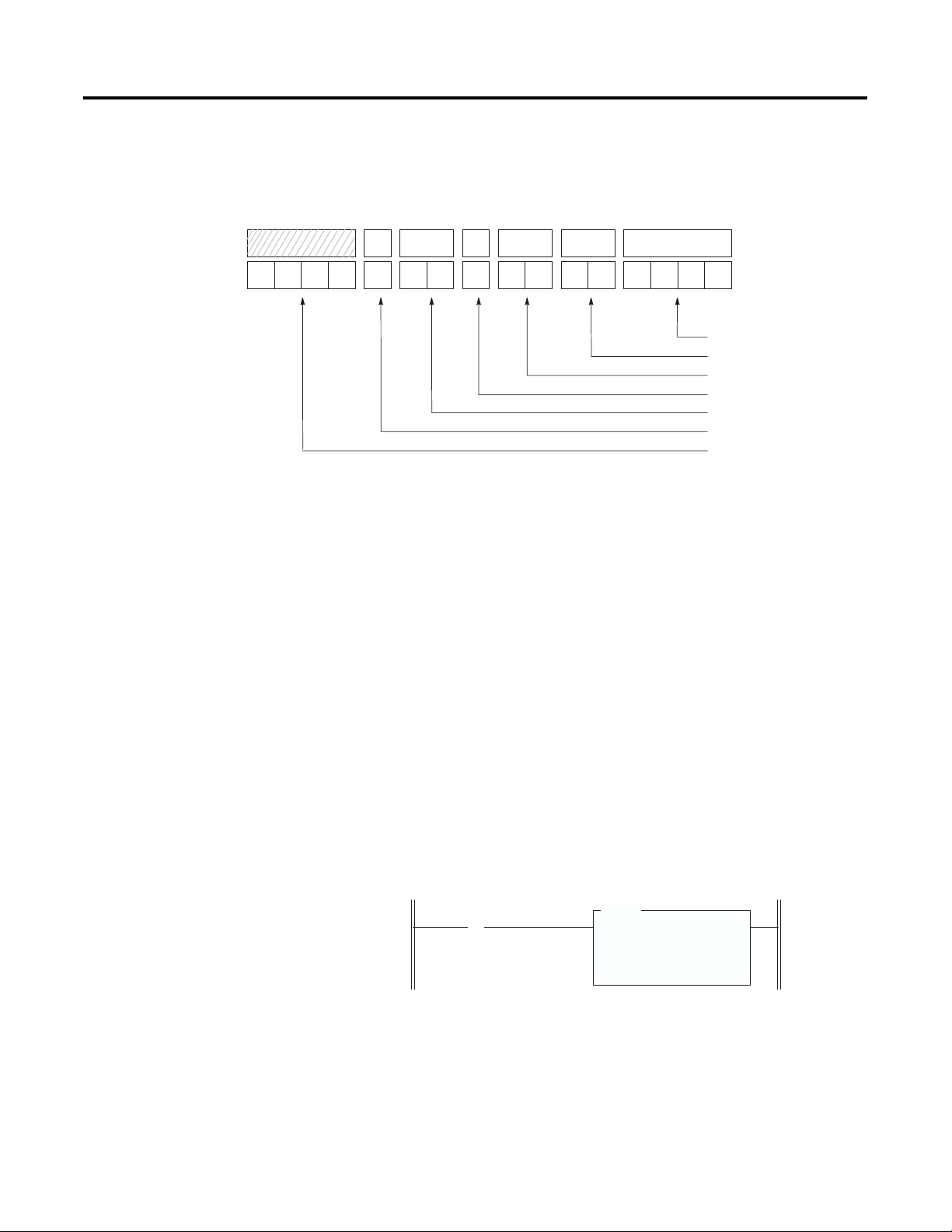
6-2 Ladder Programming Examples
Example - Configure four channels of a thermocouple module
residing in slot 3 of a 1746 chassis. Configure each channel with the
same parameters.
0000
This example transfers configuration data and sets the channel enable
bits of all four channels with a single File Copy instruction.
Procedure
11
001
910 8
16700 01450001
Bit Number
012315 14 13 12
Bit Setting
Configures Channel For:
•
Type K Thermocouple Input
•
Engineering Units 10
•
Zero If Open Circuit
•
Fahrenheit
10 Hz Filter Frequency
•
Channel Enable Bit
•
Not Used
•
1. Create integer file N10. Integer file N10 should contain four
elements (N10:0 through N10:3).
2. Enter the configuration parameters for all four thermocouple
channels into a source integer data file N10. See Appendix B for
a channel configuration worksheet.
3. Program a rung in your ladder logic to copy the contents of
integer file N10 to the four consecutive output words of the
thermocouple module beginning with O:3.0.
First Pass Bit
S:1
] [
15
On power up, bit S:1/15 is set for the first program scan, and integer file N10
is sent to the NT4 channel configuration words.
Initialize NT4
COP
COPY
FILE
Source #N10:0
Dest #O:3.0
Length 4
Publication 1746-UM007C-EN-P - July 2004
Page 73

Ladder Programming Examples 6-3
Dynamic Programming
Rung 2:1
The following example explains how to change data in the channel
configuration word when the channel is currently enabled.
Example - Execute a dynamic configuration change to channel 2 of
the thermocouple module located in slot 3 of a 1746 chassis. Change
from monitoring an external type K thermocouple to monitoring the
CJC sensors mounted on the terminal block. This gives a good
indication of what the temperature is inside the control cabinet.
Finally, set channel 2 back to type K thermocouple.
Program Listing
Set up all four channelsRung 2:0
S:1
] [
15
Set channel 2 to CJC
I:1.0
] [
0
B3
[OSR]
0
COP
COPY
FILE
Source #N10:0
Dest #O:3.0
Length 4
MOV
MOVE
Source N10:4
Dest O:3.2
Rung 2:2
Rung 2:3
address 15 data 0 address 15 data 0
N10:0 0000 1001 0001 0001 N10:3 0000 1001 0001 0001
N10:1 0000 1001 0001 0001 N10:4 0000 1001 0001 1111
N10:2 0000 1001 0001 0001
Set channel 2 back to type K
I:1.0
]/[
Data Table
0
B3
[OSR]
MOV
MOVE
1
END
Source N10:2
Dest O:3.2
IMPORTANT
While the module performs the configuration
alteration, it does not monitor input device data
change at any channel. Refer to page 4-9, Channel
Turn-On, Turn-Off, and Reconfiguration Times.
Publication 1746-UM007C-EN-P - July 2004
Page 74

6-4 Ladder Programming Examples
Verifying Channel Configuration Changes
When executing a dynamic channel configuration change, there will
always be a delay from the time the ladder program makes the change
to the time the NT4 gives you a data word using that new
configuration information. Therefore, it is very important to verify that
a dynamic channel configuration change took effect in the NT4
module, particularly if the channel being dynamically configured is
used for control. The following example explains how to verify that
channel configuration changes have taken effect.
Example - Execute a dynamic configuration change to channel 2 of
the thermocouple module located in slot 3 of a 1746 chassis, and set
an internal “data valid” bit when the new configuration has taken
effect.
Program Listing
Set up all four channels.Rung 2:0
COP
COPY
FILE
Source #N10:0
Dest #O:3.0
Length 4
MOV
MOVE
Source N10:4
Dest O:3.2
Rung 2:1
S:1
] [
15
Set channel 2 to CJC.
I:1.0
] [
0
B3
[OSR]
0
Rung 2:2
Rung 2:3
Rung 2:4
address 15 data 0 address 15 data 0
N10:0 0000 1001 0001 0001 N10:3 0000 1001 0001 0001
N10:1 0000 1001 0001 0001 N10:4 0000 1001 0001 1111
N10:2 0000 1001 0001 0001
Set channel 2 back to type K.
I:1.0
Check that the configuration written to channel 2 is
being echoed back in channel 2's status word.
EQUAL
Source
Source B
Data Table
]/[
0
EQU
B3
[OSR]
A
1
I:3.6
O:3.2
END
MOV
MOVE
Source N10:2
Dest O:3.2
Data valid
B3
( )
3
Publication 1746-UM007C-EN-P - July 2004
Page 75

Ladder Programming Examples 6-5
Interfacing to the PID Instruction
Rung 2:1
Rung 2:2
Rung 2:3
The thermocouple module was designed to interface directly to the
SLC 5/02 or later processor PID instruction without the need for an
intermediate scale operation.
Example - Use NT4 channel data as the process variable in the PID
instruction.
1. Select scaled-for-PID as the data type in the channel
configuration word.
2. Specify the thermocouple channel data word as the process
variable for the PID instruction.
Program Listing
First Pass Bit
S:1
] [
15
Channel 0
Status
I:3.4
] [
11
The Rate and Offset parameters should
be set per your application. The Dest
will typically be an analog output channel. Refer to your programming device's
user manual or Analog I/O Modules
User Manual for specific examples of
the SCL instruction.
PID
PID
Control
Process Variable
Control Variable
Control Block Length
SCALE
Source N11:23
Rate
Offset
Dest
END
Initialize NT4
Channel 0Rung 2:0
MOV
MOVE
Source N10:0
Dest O:3.0
Block
SCL
N11:0
[/10000]
2081
0
I:3.0
N11:23
23
Data Table
address 15 data 0 address 15 data 0
N10:0 0000 1000 0010 0001
Publication 1746-UM007C-EN-P - July 2004
Page 76

6-6 Ladder Programming Examples
Monitoring Channel Status Bits
This example shows how you could monitor the open circuit error
bits of each channel and set an alarm in the processor if one of the
thermocouples opens. An open circuit error can occur if the
thermocouple breaks, one of the thermocouple wires gets cut or
disconnected from the terminal block, or if the CJC thermistors are not
installed or are damaged.
IMPORTANT
If a CJC thermistor is not installed or is damaged, all
four alarms are set, and all four channel LEDs blink.
Program Listing
Rung 2:0
Rung 2:1 Channel 0
First Pass Bit
S:1
Status
I:3.4
] [
] [
15
11
Channel 0
Open
I:3.4
] [
12
Initialize NT4
COP
COPY
FILE
Source #N10:0
Dest #O:3.0
Length 4
Channel 0
Alarm
O:2.0
( )
0
Rung 2:2 Channel 1
Rung 2:3 Channel 2
Rung 2:4 Channel 3
Rung 2:5
address 15 data 0 address 15 data 0
N10:0 0000 1001 0001 0001 N10:3 0000 1001 0001 0001
N10:1 0000 1001 0001 0001
N10:2 0000 1001 0001 0001
Data Table
Status
I:3.5
] [ ] [
11
Status
I:3.6
11
Status
I:3.7
] [
11
Channel 1
Open
I:3.5
Channel 2
Open
I:3.6
Channel 3
Open
I:3.7
] [] [
] [
12
12
12
END
Channel 1
Alarm
O:2.0
Channel 2
Alarm
O:2.0
Channel 3
Alarm
O:2.0
( )
( )
( )
1
2
3
Publication 1746-UM007C-EN-P - July 2004
Page 77

Ladder Programming Examples 6-7
Invoking Autocalibration
Autocalibration of a channel occurs whenever a channel is enabled, or
when a change is made to its input type or filter frequency. You can
also command your module to perform an autocalibration cycle by
disabling a channel, waiting for the status bit to change state (1 to 0)
and then re-enabling that channel. Several channel cycles are required
to perform an autocalibration
IMPORTANT
To maintain system accuracy we recommend that you periodically
perform an autocalibration cycle, for example:
• whenever an event occurs that greatly changes the internal
temperature of the control cabinet, such as opening or closing
its door
• at a convenient time when the system is not making product,
such as during a shift change
During autocalibration the module is not converting
input data.
Several channel cycles are required to perform an autocalibration, and
it is important to remember that during autocalibration the module is
not converting input data.
Publication 1746-UM007C-EN-P - July 2004
Page 78

6-8 Ladder Programming Examples
Example - Command the NT4 to perform an autocalibration of
channel 0. The NT4 is in slot 3.
Program Listing
Rung 2:0 Channel 0 Enable
Rung 2:0 Channel 0 Enable
Condition for
Autocalibration
I:1
] [
0
Channel 0 Status
I:3.4
]/[
11
IMPORTANT
B3
[OSR]
0
Channel 0 Flag
B3
] [
1
O:3.0
(U)
11
Channel 0 Flag
B3
(L)
1
O:3.0
(L)
11
Channel 0 Flag
B3
(U)
1
The NT4 responds to processor commands much
more frequently than it updates its own LEDs.
Therefore, it is normal to execute these two rungs
and have the NT4 perform an autocalibraion of
channel 0 without the channel 0 LED ever changing
state.
Publication 1746-UM007C-EN-P - July 2004
Page 79

Chapter
7
Module Diagnostics and Troubleshooting
This chapter describes troubleshooting using the channel status LEDs
as well as the module status LED. It explains the types of conditions
that might cause an error to be reported and gives suggestions on
how to resolve the problem. This chapter includes:
• Module Operation vs. Channel Operation
• Power-up Diagnostics
• Channel Diagnostics
• LED Indicators
• Troubleshooting Flowchart
• Replacement Parts
• Contacting Rockwell Automation
Module Operation vs Channel Operation
Power-up Diagnostics
The thermocouple module performs operations at two levels:
• module level operations
• channel level operations
Module level operations include functions such as power–up
configuration and communication with the SLC processor.
Channel level operations describe channel-related functions, such as
data conversion and open-circuit detection.
Internal diagnostics are performed at both levels of operation and any
error conditions detected are immediately indicated by the module’s
LEDs.
At module powerup, a series of internal diagnostic tests is performed.
These diagnostic tests must be successfully completed or a module
error results and the module status LED remains off.
1 Publication 1746-UM007C-EN-P - July 2004
Page 80

7-2 Module Diagnostics and Troubleshooting
Channel Diagnostics
When a channel is enabled (bit 11 = 1), a diagnostic check is
performed to see that the channel has been properly configured. In
addition the channel is tested for out-of-range and open-circuit faults
on every scan. If the channel is configured for thermocouple input or
CJC input, the CJC sensors are also checked for out-of-range and open
circuits.
A failure of any channel diagnostic test causes the faulted channel
status LED to blink. All channel faults are indicated in bits 12-15 of the
channel’s status word. Channel faults are self-clearing, and the
channel LED will stop blinking and resume steady illumination when
the fault conditions are corrected.
IMPORTANT
If you clear (0) a channel enable bit (11) all channel
status information is reset.
Publication 1746-UM007C-EN-P - July 2004
Page 81

Module Diagnostics and Troubleshooting 7-3
LED Indicators
The thermocouple module has five LEDs. Four of these are channel
status LEDs numbered to correspond to each of the thermocouple’s
input channels, and one is a module status LED.
INPUT
CHANNEL
STATUS
MODULE STATUS
THERMOCOUPLE/mV
If
Module
Status
LED is:
And
Channel
Status
LED is:
Indicated Condition: Corrective action:
On On Channel Enabled No action required.
Blinking Open Circuit Condition To determine the exact error, check the
Out-of-Range
Condition
Channel Configuration
Error
Off Power-Up No action required.
012
3
Channel LEDs
Module Status LED
error bits in the input image. Check the
channel configuration word for valid data.
Make sure that the input type is indicated
correctly in bits 0-3, and that the open
circuit selection state (bits 6 and 7) is valid.
Refer to the troubleshooting flowchart on
page 7-6 and chapter 5 for more
information.
Channel Not Enabled No action required. For an example of how
to enable a channel refer to chapter 2,
Quick Start for Experienced Users, or
chapter 6, Programming Examples.
If Module
Indicated condition: Corrective action:
Status
LED is:
On Proper Operation No action required.
Off Module Fault Cycle power. If condition persists, call your local
distributor or Rockwell Automation for assistance.
Publication 1746-UM007C-EN-P - July 2004
Page 82

7-4 Module Diagnostics and Troubleshooting
Channel Status LEDs (Green)
The channel LED is used to indicate channel status and related error
information contained in the channel status word. This includes
conditions such as:
• normal operation
• channel-related configuration errors
• open circuit errors
• out-of-range errors
All channel errors are recoverable errors and after corrective action,
normal operation resumes.
Invalid Channel Configuration
Whenever a channel’s configuration word is improperly defined, the
channel LED blinks and bit 15 of the channel status word is set.
Configuration errors occur when the input type (bits 0-3 in the
channel configuration word) is invalid, or when the open circuit state
selection (bits 6 and 7) is invalid.
Open Circuit Detection
An open-circuit test is performed on all enabled channels. Whenever
an open circuit condition occurs (see possible causes listed below),
the channel LED blinks and bit 12 of the channel status word is set.
Possible causes of an open circuit include:
• The thermocouple may be broken.
• A thermocouple wire may be loose or cut.
• The thermocouple may not have been installed on the
configured channel.
• The CJC may be damaged.
Publication 1746-UM007C-EN-P - July 2004
If a damaged CJC termination is the cause of the detected open circuit
condition, the status LED for each channel configured for
thermocouple or CJC input blinks.
If an open-circuit is detected, the channel data word reflects input
data as defined by the open-circuit bits (6 and 7) in the channel
configuration word.
Page 83

Module Diagnostics and Troubleshooting 7-5
Out-Of-Range Detection
Whenever the data received at the channel data word is out of the
defined operating range, an over-range or under-range error is
indicated and bit 13 (under-range) or 14 (over-range) of the channel
status word is set. Refer to the temperature ranges provided in the
table on page 5-9 for a review of the temperature range limitations for
your input device.
Possible causes of an out-of-range condition include:
• The temperature is too hot or too cold for the thermocouple
being used.
• A type B thermocouple may be registering a °F value in
engineering units x 1 that cannot be expressed by the data bits.
Refer to page 5-11 for more information.
• A CJC may be damaged or the temperature within the cabinet
containing the module may be outside the CJC range limits.
Module Status LED (Green)
The module status LED is used to indicate module-related diagnostic
or operating errors. These non-recoverable errors may be detected at
power-up or during module operation. Once in a module error state,
the thermocouple module no longer communicates with the SLC
processor. Channel states are disabled, and data words are cleared (0).
Failure of any diagnostic test results in a non-recoverable error and
requires the assistance of your local distributor or Rockwell
Automation.
Publication 1746-UM007C-EN-P - July 2004
Page 84
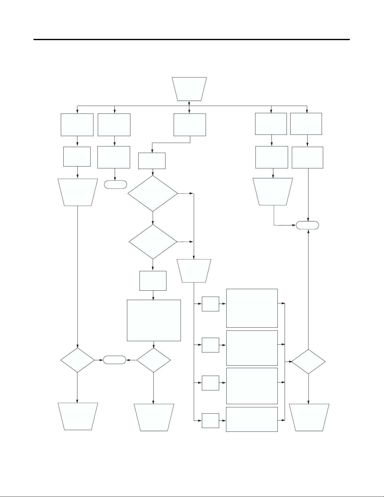
7-6 Module Diagnostics and Troubleshooting
Troubleshooting Flowchart
Check LEDs
on module.
Module
Status LED of
Module fault
condition
Check to see
that module is
seated properly
in chassis.
Cycle power.
.
f
Module
Status LED on
Normal module
operation
End
Fault
condition
Are
faulted channel(s)
configured for mV or
thermocouple
input?
thermocouple
Is more than one
LED blinking?
Ye s
CJC fault
has occurred
Check
that wiring is secure at
both CJC assemblies and that
the temperature within the
enclosure is in the range limits
of the CJC sensor
. Retry.
Channel
Status LED(s)
blinking
mV
No
Check channel
status word
bits 12 15.
Channel
Status LED
off.
Channel is
not enabled.
Enable channel if
desired by setting
channel config.
word (bit 1
1 = 1).
Retry.
Channel
Status LED
on.
Channel enabled
and working
properly
End
_
Bit 15
set (1)
Configuration error
configuration word bits 0-3
for valid input type
configuration as well as bits
6 and 7 for valid
configuration setting.
. Check
Retry.
Is problem
corrected?
Contact your local
distributor or
Rockwell
Automation.
Yes
End
No
Publication 1746-UM007C-EN-P - July 2004
Yes
Contact your local
Is problem
corrected?
No
distributor or
Rockwell
Automation.
Bit 14
set (1)
Bit 13
set (1)
Bit 12
set (1)
Over-range condition
exists. The input signal is
greater than the high scale
limit for the channel or the
CJC connections. Correct
Under-range condition
exists. The input signal is
less than the low scale limit
for the channel or the CJC
connections. Correct and
An open-circuit condition is
present. Check channel and
CJC wiring for open or loose
connections. Retry.
and Retry
Retry.
.
.
.
Yes
Is problem
corrected?
No
Contact your local
distributor or
Rockwell
Automation.
Page 85

Module Diagnostics and Troubleshooting 7-7
Replacement Parts
Contacting Rockwell Automation
The NT4 module has the following replaceable parts:
Part Catalog Number
Replacement Terminal Block 1746-RT32
Replacement Terminal Cover 1746-R13 Series B
1746-NT4 Installation Instructions 1746-IN010
If you need to contact Rockwell Automation for assistance, please
have the following information available when you call:
• a clear statement of the problem including a description of what
the system is actually doing. Note and record the LED states;
also, note input and output image words for the NT4 module.
• a list of things you have already tried to remedy the problem
• processor type, 1747-NT4 series letter, and firmware (FRN)
number. See label on left side of processor.
• hardware types in the system including I/O modules and chassis
• fault code if the SLC processor is faulted
Publication 1746-UM007C-EN-P - July 2004
Page 86

7-8 Module Diagnostics and Troubleshooting
Publication 1746-UM007C-EN-P - July 2004
Page 87
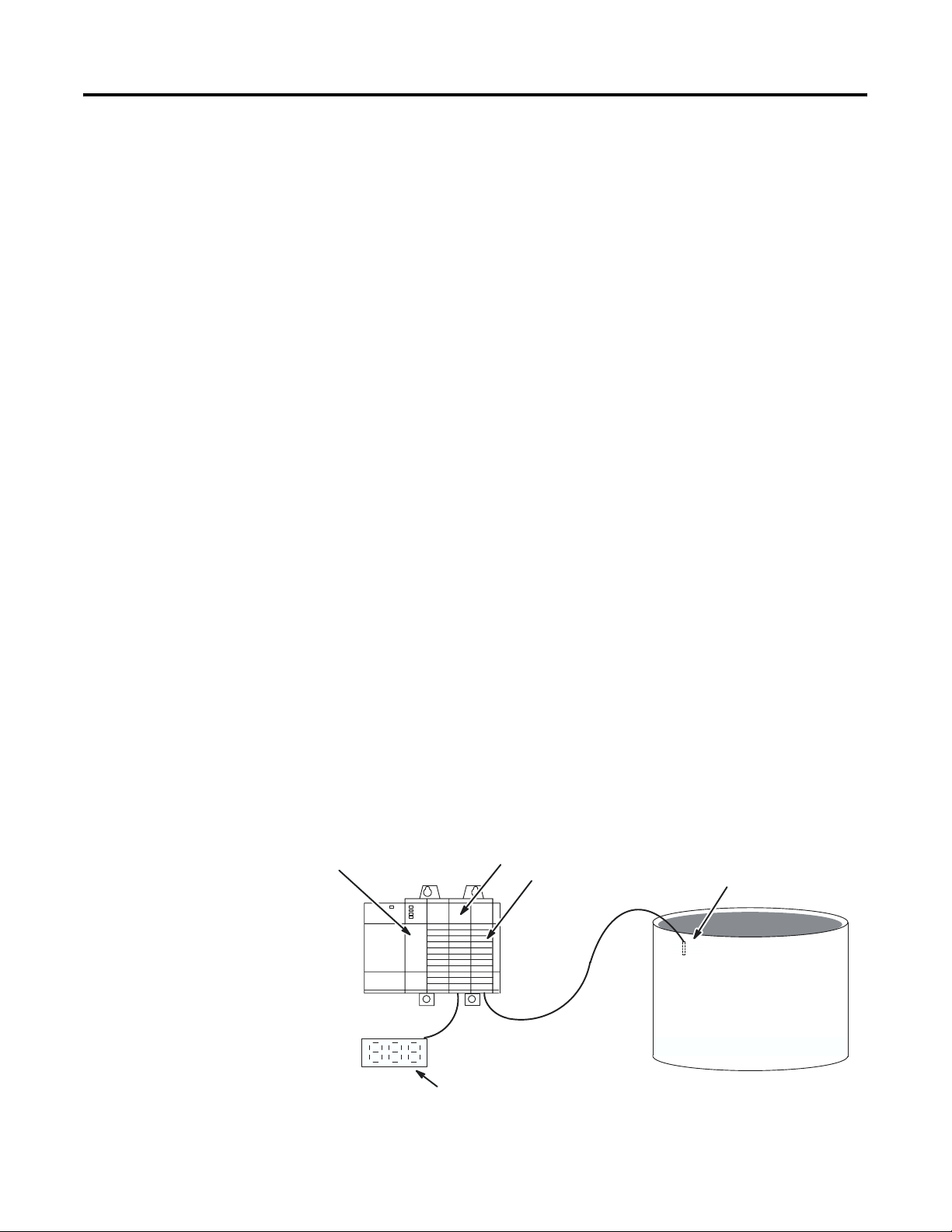
Chapter
8
Application Examples
This chapter provides two application examples to help you use the
thermocouple input module. They are defined as a:
• basic example
• supplementary example
The basic example builds on the configuration word programming
provided in chapter 6 to set up one channel for operation. This setup
is then used in a typical application to display temperature.
The supplementary example demonstrates how to perform a
dynamic configuration of all four channels. The example sets up an
application that allows you to manually select whether the displayed
thermocouple input data for any channel is expressed in °C or °F.
Basic Example
SLC 5/02
Application Setup (Display a Temperature)
This example indicates the temperature of a bath on an LED display.
The display requires BCD data, so the program must convert the
temperature reading from the thermocouple module to BCD before
sending it to the display. This application will display the temperature
in °F.
Device Configuration
1746-OB16
1746-NT4
Thermocouple Type J
Bath
LED Display
(DC sinking inputs,
BCD format)
1 Publication 1746-UM007C-EN-P - July 2004
Page 88
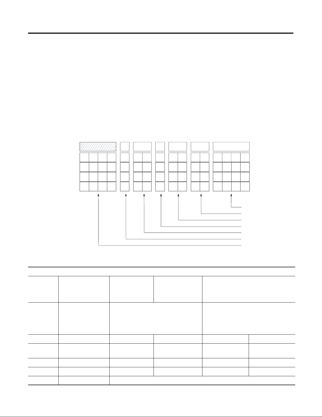
8-2 Application Examples
Channel Configuration
Configure the thermocouple channel with the following setup:
• type J thermocouple
• °F - display to whole degree
• zero data word in the event of an open circuit
• 10 Hz input filter to reject high frequency noise and give good
rejection of 60 Hz line noise
Channel Configuration Worksheet (With Settings Established for Channel 0)
11
12131415
0000
0000
0000
Bits:
0-3 Input Type Select 0000 = J
0001 = K
0010 = T
0011 = E
0010000
910 8
0100 = R
0101 = S
0110 = B
0111 = N
67
1
00 01450000
1000 = ±50 mV
1001 = ±100 mV
1111 = CJC temperature
0123
Bit Number
Channel
Channel 1
Channel 2
Channel 3
•
Input Type Select
Data Format Select
•
Open Circuit Select
•
•
Temperature Units Select
Filter Frequency Select
•
•
Channel Enable
•
Not Used
0
4 and 5 Data Format Select 00 = engineering units, x1 (0.1°/step,
0.01 mV/step)
10 = scaled-for-PID (0 to 16383)
11 = proportional counts (-32768 to +32767)
01 = engineering units, x10 (1°/step,
0.1 mV/step)
6 and 7 Open Circuit Select 00 = zero 01 = upscale 10 = downscale
8 Temperature Units
0 = degrees Celsius 1 = degrees Fahrenheit
Select
9 and 10 Filter Frequency Select 00 = 10 Hz 01 = 50 Hz 10 = 60 Hz 11 = 250 Hz
11 Channel Enable 0 = channel disabled 1 = channel enabled
12-15 Not Used 0000 = always make this setting
Publication 1746-UM007C-EN-P - July 2004
Page 89

Program Listing
Application Examples 8-3
Rung 2.0
First Pass Bit
S:1
] [
15
Rung 2.1
Convert the channel 0 data word (degrees F) to BCD and write this to the LED display.
If channel 0 is ever disabled, a zero is written to the display..
Initialize Channel 0
of NT4
MOV
MOVE
Source N10:0
Dest O:3.0
TOD
TO
BCD
Source I:3.0
Dest N7:0
MVM
MASKED MOVE
Source N7:0
Mask 0FFF
Dest O:2.0
Rung 2.2
END
The use of the masked move instruction with the 0FFF mask allows you to use outputs 12, 13,
14, and 15 for other output devices in your system. The 7-segment display uses outputs 0-11.
.
Data Table
address 15 data 0 address 15 data 0
N10:0 0000 1001 0001 0000
Publication 1746-UM007C-EN-P - July 2004
Page 90

8-4 Application Examples
Supplementary Example
1746-NT4
SLC 5/02
Application Setup (Four Channels °C - °F)
This example shows how to display the temperature of several
different thermocouples at one annunciator panel. A selector switch
(I:2/0) allows the operator to choose between displaying data in °C
and °F. A second selector switch (I:2/1) allows the operator to switch
one of the displays between the ambient temperature near the bath
and the temperature inside of the control cabinet that houses the SLC
500. Each of the displays is a 4-digit, 7-segment LED display with the
last digit representing tenths of a degree. The displays have
DC-sinking inputs and use a BCD data format.
Device Configuration
1746-IB8
(5).1746-OB16
Ambient Temperature
Thermocouple Type T
Display Panel
Cabinet
Cabinet
Ambient
BathAmbient
. .
Selector Switches
(I:2/1) and (I:2/0)
. .
m
Chilled H2OSteam
°
F
°
C
Bath
Thermocouple
Type J
Chilled H2O Pipe
Type J
Chilled Thermocouple
Type K
Steam Thermocouple
Steam Pipe
Publication 1746-UM007C-EN-P - July 2004
Page 91

Application Examples 8-5
Channel Configuration
Configuration setup for ambient thermocouple:
• channel 0
• type T thermocouple
• display temperature to tenths of a degree
• zero data word in the event of an open circuit
• 60 Hz input filter to provide 60 Hz line noise rejection
Configuration setup for bath thermocouple:
• channel 1
• type J thermocouple
• display temperature to tenths of a degree
• zero data word in the event of an open circuit
• 60 Hz input filter to provide 60 Hz line noise rejection
Configuration setup for steam thermocouple:
• channel 2
• type K thermocouple
• display temperature to tenths of a degree
• zero data word in the event of an open circuit
• 60 Hz input filter to provide 60 Hz line noise rejection
Configuration setup for chilled H2O thermocouple:
• channel 3
• type J thermocouple
• display temperature to tenths of a degree
• zero data word in the event of an open circuit
• 60 Hz input filter to provide 60 Hz line noise rejection
Configuration setup for cabinet temperature:
• channel 0
• CJC temperature
• display temperature to tenths of a degree
• zero data word in the event of an open circuit
• 60 Hz input filter to provide 60 Hz line noise rejection
Publication 1746-UM007C-EN-P - July 2004
Page 92
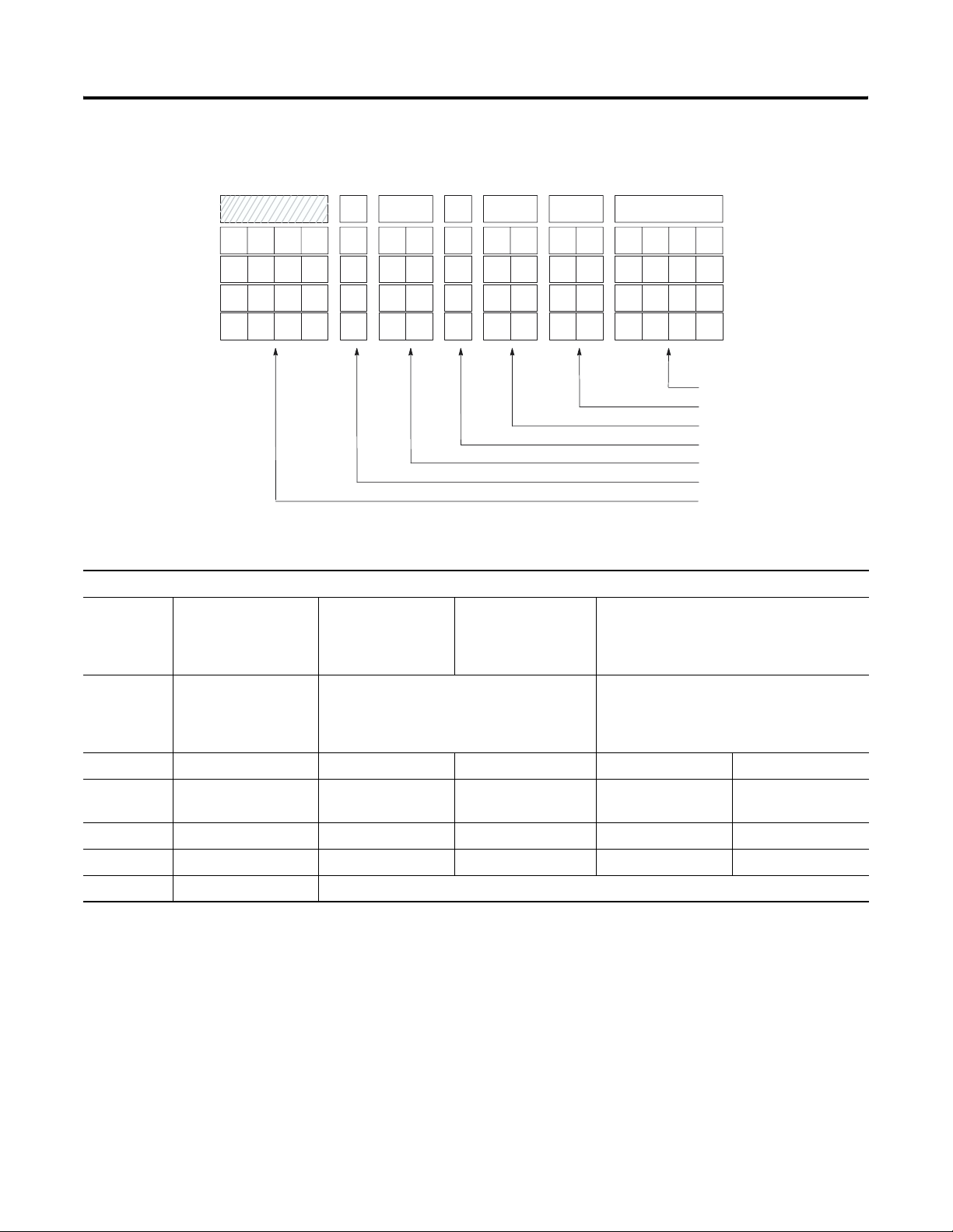
8-6 Application Examples
Channel Configuration Worksheet (With Settings Established)
11
12131415
0000
0000
0000
Bits:
0-3 Input Type Select 0000 = J
0001 = K
0010 = T
0011 = E
1010000
101
101
101
910 8
x6700 00450010
x
x
x
0100 = R
0101 = S
0110 = B
00
00
00
00
00
00
0000
0001
0000
1000 = ±50 mV
1001 = ±100 mV
1111 = CJC temperature
0111 = N
0123
Bit Number
Channel 0
Channel 1
Channel 2
Channel 3
•
Input Type Select
•
Data Format Select
Open Circuit Select
•
Temperature Units Select
•
Filter Frequency Select
•
•
Channel Enable
•
Not Used
(Ambient)
(Bath)
(Steam)
(Chilled
H2O)
4 and 5 Data Format Select 00 = engineering units, x1 (0.1°/step,
0.01 mV/step)
10 = scaled-for-PID (0 to 16383)
11 = proportional counts (-32768 to +32767)
01 = engineering units, x10 (1°/step,
0.1 mV/step)
6 and 7 Open Circuit Select 00 = zero 01 = upscale 10 = downscale
8 Temperature Units
0 = degrees Celsius 1 = degrees Fahrenheit
Select
9 and 10 Filter Frequency Select 00 = 10 Hz 01 = 50 Hz 10 = 60 Hz 11 = 250 Hz
11 Channel Enable 0 = channel disabled 1 = channel enabled
12-15 Not Used 0000 = always make this setting
Publication 1746-UM007C-EN-P - July 2004
Page 93

Application Examples 8-7
Program Setup and Operation Summary
1. Set up two configuration words in memory for each channel,
one for °C and the other for °F. In addition, set up two
configuration words to monitor the thermocouple’s CJC
temperature. Monitoring the CJC temperature gives a good
indication of the temperature inside of the control cabinet the
SLC is mounted in. The table below shows the configuration
word allocation summary.
Channel Configuration Word Allocation
°F °C
1 N10:0 N10:4
2 N10:1 N10:5
3 N10:2 N10:6
4 N10:3 N10:7
CJC N10:8 N10:9
2. When the positions of the degrees selector switch or
ambient/cabinet selector switch change, write the appropriate
channel configurations to the NT4 module. Note that the use of
the OSR instruction (one-shot rising) makes these configuration
changes edge-triggered, i.e. the NT4 is reconfigured only when a
selector switch changes position.
C
°
F
Cabinet
Selector Switches:
Ambient
°
3. Monitor the channel 0 status word to determine which
temperature is being displayed (ambient or cabinet) and
energize the appropriate pilot light.
4. Convert the individual thermocouple data words to BCD and
send the data to the respective LED displays.
Program Listing
The first six rungs of the program starting on the next page send the
correct channel setup information to the NT4 module based on the
position of the two selector switches.
Publication 1746-UM007C-EN-P - July 2004
Page 94

8-8 Application Examples
Rung 2.0
If the degrees selector switch is turned to the Fahrenheit position, set up all four channels to read in
degrees Fahrenheit. The default for channel 0 is to read the ambient temperature thermocouple.
Degrees
Selector Switch Fahrenheit
I:2.0
] [
0
B3
OSR
0
Configure NT4
Channels
COP
COPY
FILE
Source #N10:0
Dest #O:1.0
Length 4
Rung 2.1
If the ambient/cabinet selector switch is turned to the ambient position and the degrees selector
switch is in the Farenheit position, configure channel 0 to read the ambient temperature
thermocouple in degrees Fahrenheit.
Degrees
Selector Switch Fahrenheit
I:2.0
] [
0
Ambient/Cabinet
Selector Switch Ambient
I:2.0
] [
1
B3
OSR
Configure NT4
Channels
MOV
MOVE
1
Source N10:0
Dest O:1.0
Rung 2.2
If the ambient/cabinet selector switch is turned to the cabinet position and the degrees selector
switch is in the Farenheit position, configure channel 0 to read the CJC sensor on the NT4 module
in degrees Fahrenheit.
Degrees
Selector Switch Fahrenheit
I:2.0
] [
0
Rung 2.3
If the degrees selector switch is turned to the Celsius position, set up all four channels to read in
degrees Celsius. The default for channel 0 is to read the ambient temperature thermocouple.
Ambient/Cabinet
Selector Switch Ambient
I:2.0
]/[
1
B3
OSR
Configure NT4
Channels
MOV
MOVE
2
Source N10:8
Dest O:1.0
Degrees
Selector Switch Celsius
I:2.0
Publication 1746-UM007C-EN-P - July 2004
]/[
0
B3
OSR
Configure NT4
Channels
COP
COPY
FILE
3
Source #N10:4
Dest #O:1.0
Length 4
Page 95

Application Examples 8-9
Rung 2.4
If the ambient/cabinet selector switch is turned to the ambient position and the degrees selector
switch is in the Celsius position, configure channel 0 to read the ambient temperature
thermocouple in degrees Celsius.
Degrees
Selector Switch Celsius
I:2.0
]/[
0
Ambient/Cabinet
Selector Switch Ambient
I:2.0
] [
1
B3
OSR
Configure NT4
Channels
MOV
MOVE
4
Source N10:4
Dest O:1.0
Rung 2.5
If the ambient/cabinet selector switch is turned to the cabinet position and the degrees selector
switch is in the Celsius position, configure channel 0 to read the CJC sensor on the NT4 module in
degrees Celsius.
Degrees
Selector Switch Celsius
I:2.0
] [
0
Rung 2.6
If channel 0 is set up for reading the ambient thermocouple, energize the ambient pilot light on
the annunciator panel.
MEQ
MASKED
Source I:1.4
Mask FEFF
Compare N1
0:4
Ambient/Cabinet
Selector Switch Cabinet
I:2.0
EQUAL
]/[
1
B3
OSR
Configure NT4
Channels
MOV
MOVE
5
Source N10:9
Dest O:1.0
Ambient Light
O:7.0
( )
0
Rung 2.7
If channel 0 is set up for reading the CJC sensor on the NT4 module, energize the cabinet pilot
light on the annunciator panel.
Cabinet Light
MEQ
MASKED
EQUAL
Source I:1.4
O:7.0
( )
1
Mask FEFF
Compare N10:9
Publication 1746-UM007C-EN-P - July 2004
Page 96

8-10 Application Examples
Rung 2.8
Convert the NT4 data words to BCD format and send to the LED displays.
Rung 2.9
Rung 2.10
Rung 2.11
Write NT4
Ambient or Cabinet
Temperature to Display
TOD
TO
BCD
Source I:1.0
Dest O:3.0
Write NT4
Bath
Temperature to Display
TOD
TO
BCD
Source I:1.1
Dest O:4.0
Write NT4
Steam
Temperature to Display
TOD
TO
BCD
Source I:1.2
Dest O:5.0
Write NT4 Chilled
Temperature to Display
TOD
TO
BCD
Source I:1.3
address 15 data 0 address 15 data 0
N10:0 0000 1101 0000 0010 N10:5 0000 1100 0000 0000
N10:1 0000 1101 0000 0000 N10:6 0000 1100 0000 0001
N10:2 0000 1101 0000 0001 N10:7 0000 1100 0000 0000
N10:3 0000 1101 0000 0000 N10:8 0000 1101 0000 1111
N10:4 0000 1100 0000 0010 N10:9 0000 1100 0000 1111
Publication 1746-UM007C-EN-P - July 2004
Dest O:6.0
Rung 2.12
END
Data Table
Page 97

Electrical Specifications
Appendix
Specifications
This appendix lists the specifications and input resolution curves for
the 1746-NT4 4-Channel Thermocouple/mV Input Module.
Specification Value
A
Backplane Current
Consumption
Backplane Power
Consumption
Number of Channels 4 (backplane isolated)
I/O Chassis Location Any I/O module slot except slot 0
A/D Conversion Method Sigma-Delta Modulation
Input Filtering Low pass digital filter with programmable notch (filter)
Normal Mode Rejection
(between [+] input and [-]
input)
Common Mode Rejection
(between inputs and chassis
ground)
Input Filter Cut-Off
Frequencies
Calibration Module autocalibrates at power-up and whenever a channel
Isolation 500V dc continuous between inputs and chassis ground, and
60 mA at 5V dc
40 mA at 24V dc
0.8W maximum (0.3W @ 5V dc, 0.5W @ 24V dc)
frequencies
Greater than 100 dB at 50 Hz (10 Hz, 50 Hz filter frequencies)
Greater than 100 dB at 60 Hz (10 Hz, 60 Hz filter frequencies)
Greater than 150 dB at 50 Hz (10 Hz, 50 Hz filter frequencies)
Greater than 150 dB at 60 Hz (10 Hz, 60 Hz filter frequencies)
2.62 Hz at 10 Hz filter frequency
13.1 Hz at 50 Hz filter frequency
15.72 Hz at 60 Hz filter frequency
65.5 Hz at 250 Hz filter frequency
is enabled.
between inputs and backplane.
Maximum
Channel-to-Channel
Common-Mode Separation
1 Publication 1746-UM007C-EN-P - July 2004
Series B or later: 2V maximum between any two channels
Series A: 0V separation
Page 98
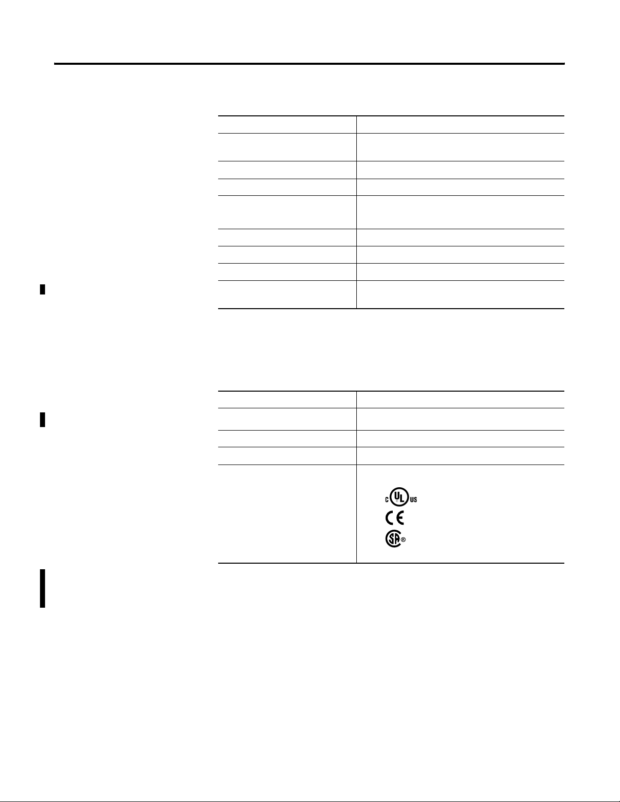
A-2 Specifications
Physical Specifications
Specification Value
LED Indicators 5, green status indicators, one for each of 4 channels
and one for module status
Module ID Code 3510
Recommended Cable:
For Thermocouple inputs Appropriate shielded twisted pair thermocouple
extension wire
(1)
For mV inputs Belden #8761 or equivalent
Maximum Wire Size Two 14 AWG wires per terminal
Environmental Specifications
Maximum Cable Impedance 25
ohms maximum loop impedance, for <1LSB error
Terminal Block Removable, Allen-Bradley spare part Catalog Number
1746-RT32
(1) Refer to the thermocouple manufacturer for the correct extension wire.
Specification Value
Operating Temperature
(1)
0°C to 60°C (32°F to 140°F)
Storage Temperature -40°C to +85°C (-40°F to +185°F)
Relative Humidity 5% to 95% (without condensation)
Certification
C-UL Listed Industrial Control Equipment
for use in Class 1, Div 2 Hazardous
Locations
Marked for all applicable directives
CSA approved
Publication 1746-UM007C-EN-P - July 2004
(1) When the NT4 module detects 0°C (32°F) [(+/- 3°C) +/- 5.4°F] at the CJC, it will detect an out-of-range condition
and set values to downscale -270°C (-454°F). It is recommended that ambient temperature surrounding the SLC
500 system be maintained above 3°C (37.4°F) in order for the NT4 module to measure temperature correctly
without detecting an out-of-range condition.
Page 99

Input Specifications
Specification Value
Type of Input (Selectable) Thermocouple Type J -210°C to 760°C (-346°F to 1400°F)
Thermocouple Linearization IPTS-68 standard, NBS MN-125, NBS MN-161
Cold Junction Compensation Accuracy ±1.5°C, 0°C to 85°C (32°F to 185°F)
Input Impedance Greater than 10MW
Temperature Scale (Selectable) °C or °F and 0.1°C or 0.1°F
DC Millivolt Scale (Selectable) 0.1 mV or 0.01 mV
Specifications A-3
Thermocouple Type K -270°C to 1370°C (-454°F to 2498°F)
Thermocouple Type T -270°C to 400°C (-454°F to 752°F)
Thermocouple Type E -270°C to 1000°C (-454°F to 1832°F)
Thermocouple Type R 0°C to 1768°C (32°F to 3214°F)
Thermocouple Type S 0°C to 1768°C (32°F to 3214°F)
Thermocouple Type B 300°C to 1820°C (572°F to 3308°F)
Thermocouple Type N (14 AWG) 0°C to 1300°C (32°F to 2372°F)
Millivolt (-50 mV dc to +50 mV dc)
Millivolt (-100 mV dc to +100 mV dc)
Open Circuit Detection
Leakage Current
Open Circuit Detection Method Upscale
Time to Detect Open Circuit 500 msec or 1 module update time, whichever is greater
Input Step Response See Channel Step Response, page 4–6.
Input Resolution See Input Resolution Graphs on following pages. The graphs show the
Display Resolution See Channel Data Word, page 5-12.
Overall Module Accuracy
@ 25°C (77°F)
Overall Module Accuracy
(0°C to 60°C, 32°F to 140°F)
Overall Module Drift See 1746-NT4 Module Accuracy, page A-4
Module Update Time See Update Time, page 4-7
Channel Turn-On Time,
Reconfiguration Time
12 nA maximum
smallest measurable unit based on the combined hardware and software
tolerances.
See 1746-NT4 Module Accuracy, page A-4
See 1746-NT4 Module Accuracy, page A-4
Requires up to one module update time plus one of the following:
50 Hz Filter= 82 milliseconds
60 Hz Filter= 196 milliseconds
50 Hz Filter= 226 milliseconds
10 Hz Filter= 946 milliseconds
Channel Turn-Off Time Requires up to one module update time (refer to page 4–7)
Publication 1746-UM007C-EN-P - July 2004
Page 100

A-4 Specifications
1746-NT4 Module Accuracy
Input Resolution per
Input Type
With Autocalibration
Maximum Error
@ 25°C
(1)
Maximum Error
@ 77°F
Without Autocalibration
Temperature Drift
(0°C-60°C)
J ±1.06°C ±1.91°F ±0.0193°C/°C, °F/°F
K ±1.72°C ±3.10°F ±0.0328°C/°C, °F/°F
T ±1.43°C ±2.57°F ±0.0202°C/°C, °F/°F
E ±0.72°C ±1.3°F ±0.0190°C/°C, °F/°F
S ±3.61°C ±6.5°F ±0.0530°C/°C, °F/°F
R ±3.59°C ±6.46°F ±0.0530°C/°C, °F/°F
B ±3.12°C ±5.62°F ±0.0457°C/°C, °F/°F
N ±1.39°C ±2.5°F ±0.0260°C/°C, °F/°F
±50 mV ±50 mV ±50 mV ±1.0 mV/°C, ±1.8 mV/°F
±100 mV ±50 mV ±50 mV ±1.5 mV/°C, ±2.7 mV/°F
(1) Assumes the module terminal block temperature is stable.
(1)
Thermocouple Type at Each
Filter Frequency
˚
Resolution
250 Hz 50/60 Hz 10 Hz
12.80
23.04
9.60
17.28
6.40
11.52
3.20
5.76
(C)
(F)
1.60
2.88
1.20
2.16
0.80
1.44
0.40
0.72
˚
1.44
1.08
0.72
0.36
Type
0.8
0.6
0.4
0.2
0.0
_
300 150 0 150 300 450 600 750 900 1050 1200
_
508 238 32 302 572 842 111 2 1382 1652 1922 2192
E Thermocouple
_
_
Temperature
˚
(C)
˚
(F)
Publication 1746-UM007C-EN-P - July 2004
 Loading...