

Page 1

Installation Instructions
SLC™ 500 4-Channel Thermocouple/mV Input
Module
(Catalog Number 1746-NT4, Series B)
Inside…............................................................................................Page
For More Information............................................................................... 3
Hazardous Location Considerations .........................................................4
Environnements dangereux ..................................................................... 4
Overview ...................................................................................................5
Required Tools and Equipment................................................................ 6
Electrostatic Damage............................................................................... 7
NT4 Power Requirements........................................................................ 7
Modular Chassis Considerations............................................................. 7
Fixed Expansion Chassis Considerations................................................. 8
General Considerations ........................................................................... 8
Terminal Block Removal........................................................................... 8
Module Installation and Removal.......................................................... 10
Terminal Wiring...................................................................................... 11
Thermocouple Junctions........................................................................ 12
Wiring Considerations ........................................................................... 13
Wiring Input Devices to the NT4 ........................................................... 15
Cold-Junction Compensation (CJC) ....................................................... 16
Module Addressing................................................................................ 17
Channel Configuration ........................................................................... 17
Specifications ........................................................................................ 19
Publication 1746-IN010D-EN-P - June 2004
Page 2
2 SLC™ 500 4-Channel Thermocouple/mV Input Module
Important User Information
Solid state equipment has operational characteristics differing from those of electromechanical equipment.
Safety Guidelines for the Application, Installation and Maintenance of Solid State Controls (Publication
SGI-1.1 available from your local Rockwell Automation sales office or online at
http://www.ab.com/manuals/gi) describes some important differences between solid state equipment and
hard-wired electromechanical devices. Because of this difference, and also because of the wide variety of
uses for solid state equipment, all persons responsible for applying this equipment must satisfy themselves
that each intended application of this equipment is acceptable.
In no event will Rockwell Automation, Inc. be responsible or liable for indirect or consequential damages
resulting from the use or application of this equipment.
The examples and diagrams in this manual are included solely for illustrative purposes. Because of the many
variables and requirements associated with any particular installation, Rockwell Automation, Inc. cannot
assume responsibility or liability for actual use based on the examples and diagrams.
No patent liability is assumed by Rockwell Automation, Inc. with respect to use of information, circuits,
equipment, or software described in this manual.
Reproduction of the contents of this manual, in whole or in part, without written permission of Rockwell
Automation, Inc. is prohibited.
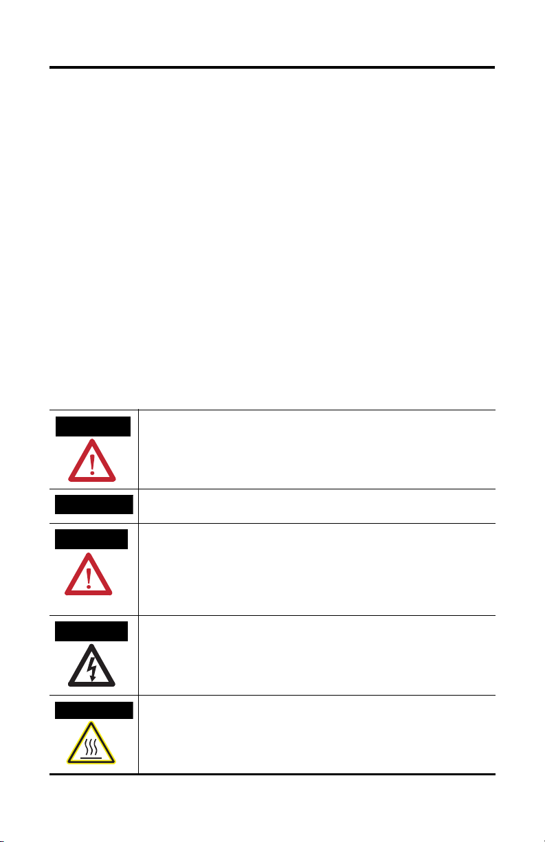
Throughout this manual we use notes to make you aware of safety considerations.
WARNING
Identifies information about practices or circumstances that can cause an explosion in a
hazardous environment, which may lead to personal injury or death, property damage,
or economic loss.
IMPORTANT
ATTENTION
SHOCK HAZARD
BURN HAZARD
Identifies information that is critical for successful application and understanding of the
product.
Identifies information about practices or circumstances that can lead to personal injury
or death, property damage, or economic loss. Attentions help you:
• identify a hazard
• avoid a hazard
• recognize the consequence
Labels may be located on or inside the drive to alert people that dangerous voltage may
be present.
Labels may be located on or inside the drive to alert people that surfaces may be
dangerous temperatures.
Publication 1746-IN010D-EN-P - June 2004
Page 3

SLC™ 500 4-Channel Thermocouple/mV Input Module 3
For More Information
Related Publications
For: Refer to this Document: Pub. No.
A more detailed description on how to install and
use your SLC 500 4-Channel Thermocouple/mV Input
Module.
A more detailed description on how to install and
use your SLC 500 Modular Hardware Style Control
System.
A more detailed description on how to install and
use your SLC 500 Fixed Hardware Style Control
System.
Thermocouple/mV Input Module
User Manual
SLC™ 500 Modular Hardware
Style User Manual
SLC™ 500 Fixed Hardware Style
Installation and Operation Manual
If you would like a manual, you can:
• download an electronic version from the internet:
www.theautomationbookstore.com
• order a printed manual by:
– contacting your local distributor or Rockwell Automation representative
– visiting www.theautomationbookstore.com
– calling 1.800.963.9548 (USA/Canada) or 001.330.725.1574 (Outside
USA/Canada)
1746-6.6.1
1747-UM011
1747-6.21
Publication 1746-IN010D-EN-P - June 2004
Page 4
4 SLC™ 500 4-Channel Thermocouple/mV Input Module
Hazardous Location Considerations
This equipment is suitable for use in Class I, Division 2, Groups A, B, C, D or
non-hazardous locations only. The following WARNING statement applies to use in
hazardous locations.
WARNING
EXPLOSION HAZARD
• Substitution of components may impair suitability for Class
I, Division 2.
• Do not replace components or disconnect equipment
unless power has been switched off or the area is known to
be non-hazardous.
• Do not connect or disconnect components unless power
has been switched off or the area is known to be
non-hazardous.
• All wiring must comply with N.E.C. article 501-4(b).
Environnements dangereux
Cet équipement est conçu pour être utilisé dans des environnements de Classe I,
Division 2, Groupes A, B, C, D ou non dangereux. La mise en garde suivante
s’applique à une utilisation dans des environnements dangereux.
WARNING
DANGER D’EXPLOSION
• La substitution de composants peut rendre cet équipement
impropre à une utilisation en environnement de Classe I,
Division 2.
• Ne pas remplacer de composants ou déconnecter
l'équipement sans s'être assuré que l'alimentation est
coupée.
• Ne pas connecter ou déconnecter des composants sans
s'être assuré que l'alimentation est coupée.
Publication 1746-IN010D-EN-P - June 2004
Page 5

SLC™ 500 4-Channel Thermocouple/mV Input Module 5
Overview
The thermocouple/mV input module receives and stores digitally converted
thermocouple and/or millivolt (mV) analog data into its image table for retrieval by
all fixed and modular SLC 500 processors. The module supports connections from
any combination of up to four thermocouple or mV analog sensors. See the input
specifications beginning on page 21 for thermocouple types, their associated
temperature ranges, and the analog input signal ranges that each 1747-NT4 channel
will support. Each input channel is individually configurable via software for a
specific input device and provides open-circuit, over-range, and under-range
detection and indication.
The module contains a removable terminal block with two cold-junction
compensation (CJC) sensors. There are no output channels on the module.
Configuration is done via the user program. There are no DIP switches.
Channel Status LEDs
Channel status LEDs indicate the status for channels 0 through 3. Related error
information is contained in the channel status word. This includes conditions such
as:
• normal operation
• channel-related configuration errors
• open-circuit errors
• out-of-range errors
All channel errors are recoverable errors.
Module Status LED
The module status LED shows diagnostic or operating errors related to the module.
These non-recoverable errors may be detected during power-up or during
operation. Once an error has been detected, the module no longer communicates
with the SLC processor. Channel states are disabled, and data words are cleared (0).
Failure of any diagnostic test results in a non-recoverable error and requires the
assistance of your local Allen-Bradley distributor or Rockwell Automation
representative.
Publication 1746-IN010D-EN-P - June 2004
Page 6
6 SLC™ 500 4-Channel Thermocouple/mV Input Module
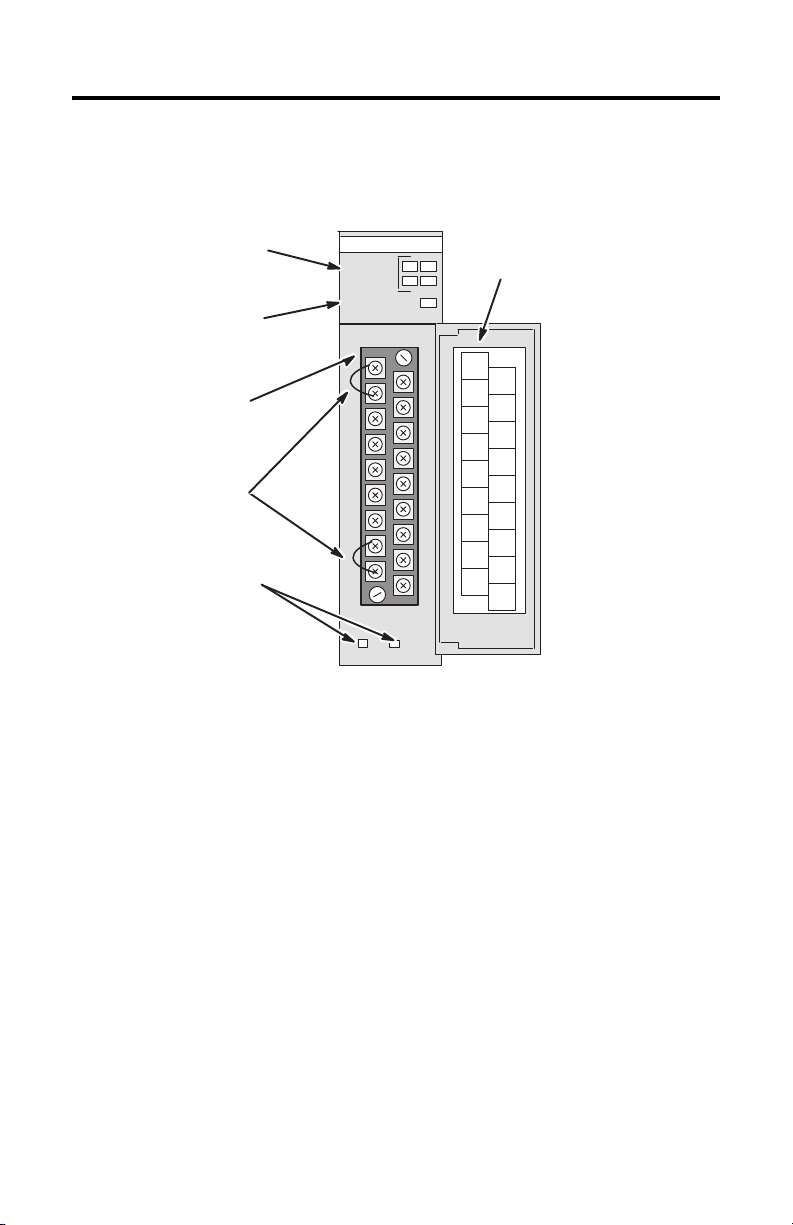
1747-NT4 Thermocouple Module Hardware Features
Channel Status
LEDs (Green)
Module Status
LED (Green)
INPUT
CHANNEL
STATUS
MODULE STATUS
THERMOCOUPLE/mV
012
3
Removable
Ter m ina l Bl ock
CJC Sensors
Cable Tie Slots
Required Tools and Equipment
Have the following tools and equipment ready:
• medium blade screwdriver
• medium cross-head screwdriver
• thermocouple or millivolt sensor
• appropriate thermocouple extension wire (if needed)
• thermocouple/mV input module (1746-NT4)
• programming equipment
Door Label
CJC A+
Do Not
Remove
CHL0+
CJC A±
Do Not
Remove
CHL0-
SHIELD
CHL1+
SHIELD
CHL1-
SHIELD
CHL2+
SHIELD
CHL2-
SHIELD
CHL3+
CJC B±
Do Not
CHL3-
Remove
CJC B+
Do Not
Remove
ANLG
COM
Publication 1746-IN010D-EN-P - June 2004
Page 7
SLC™ 500 4-Channel Thermocouple/mV Input Module 7
Electrostatic Damage
Electrostatic discharge can damage semiconductor devices inside this module if you
touch backplane connector pins. Guard against electrostatic damage by observing
the following precautions.
ATTENTION
• Wear an approved wrist strap grounding device when handling the module.
• Touch a grounded object to rid yourself of electrostatic charge before
handling the module.
• Handle the module from the front, away from the backplane connector. Do
not touch backplane connector pins.
• Keep the module in its static-shield bag when not in use, or during
shipment.
Electrostatic discharge can degrade performance or cause
permanent damage. Handle the module as stated below.
NT4 Power Requirements
The thermocouple module receives its power through the SLC 500 chassis
backplane from the fixed or modular +5V dc/+24V dc chassis power supply. The
maximum current drawn by the module is shown in the table below.
5V dc Amps 24V dc Amps
0.060 0.040
When you are using a modular system configuration, add the values shown in the
table above to the requirements of all other modules in the SLC chassis to prevent
overloading the chassis power supply.
When you are using a fixed system controller, refer to the important note on page 8
about module compatibility in a 2-slot fixed expansion chassis.
Modular Chassis Considerations
Place your thermocouple module in any slot of an SLC 500 modular, or modular
expansion chassis, except for the extreme left slot (slot 0) in the first chassis. This
slot is reserved for the processor or adapter modules.
Publication 1746-IN010D-EN-P - June 2004
Page 8

8 SLC™ 500 4-Channel Thermocouple/mV Input Module
Fixed Expansion Chassis Considerations
IMPORTANT
The 2-slot, SLC 500 fixed I/O expansion chassis (1746-A2) will
support only specific combinations of modules. If you are using
the thermocouple module in a 2-slot expansion chassis with
another SLC I/O or communication module, refer to the
SLC 500™Thermocouple/mV Input Module User Manual,
1746-6.6.1
General Considerations
Most applications require installation in an industrial enclosure to reduce the effects
of electrical interference. Thermocouple inputs are highly susceptible to electrical
noises due to the small amplitudes of their signal (microvolt/°C).
Group your modules to minimize adverse effects from radiated electrical noise and
heat. Consider the following conditions when selecting a slot for the thermocouple
module. Position the module:
• in a slot away from sources of electrical noise, such as hard-contact switches,
relays, and AC motor drives
• away from modules which generate significant radiated heat, such as
32-point I/O modules
In addition, route shielded, twisted-pair thermocouple or millivolt input wiring
away from any high-voltage I/O wiring.
Terminal Block Removal
When installing the module in a chassis, it is not necessary to remove the terminal
block from the module. However, if the terminal block is removed, use the write-on
label located on the side of the terminal block to identify the module location and
type.
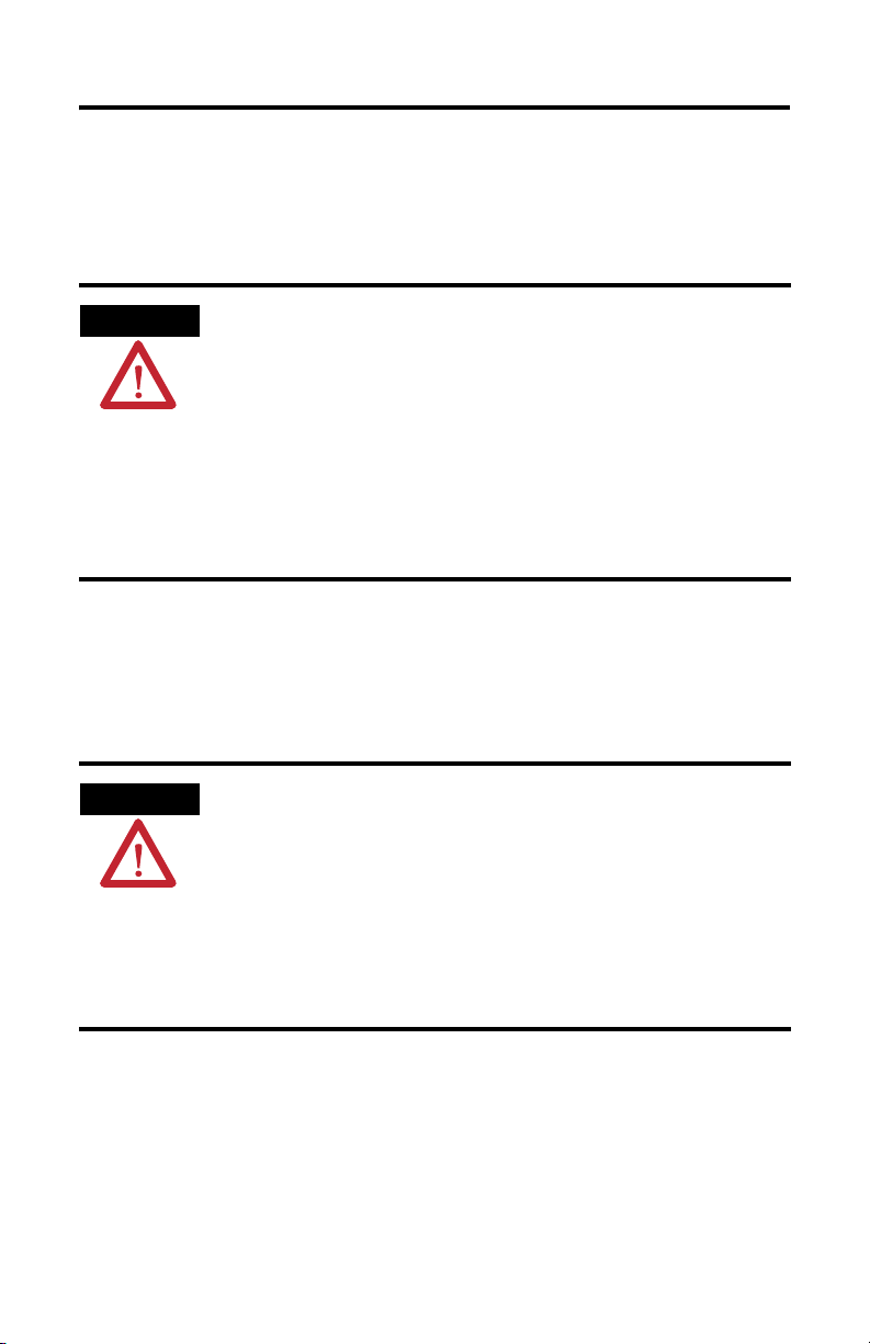
ATTENTION
Publication 1746-IN010D-EN-P - June 2004
Disconnect power to the SLC before attempting to install,
remove, or wire the removable terminal wiring block.
To avoid cracking the removable terminal block, alternate the
removal of the slotted terminal block release screws.
Page 9

SLC™ 500 4-Channel Thermocouple/mV Input Module 9
To remove the terminal block:
1. Loosen the two terminal block release screws.
2. Grasp the terminal block at the top and bottom and pull outward and down.
When removing or installing the terminal block, be careful not to damage
the CJC sensors.
Terminal Block Release Screws
CJC Sensors
Max. Torque = 0.7 to 0.9 Nm (6 to 8
in-lb)
Publication 1746-IN010D-EN-P - June 2004
Page 10

10 SLC™ 500 4-Channel Thermocouple/mV Input Module
Module Installation and Removal
Module Installation Procedure
1. Align the circuit board of the thermocouple module with the card guides
located at the top and bottom of the chassis.
2. Slide the module into the chassis until both top and bottom retaining clips
are secured. Apply firm even pressure on the module to attach it to its
backplane connector. Never force the module into the slot.
3. Cover all unused slots with the Card Slot Filler, Catalog Number 1746-N2.
Top and Bottom Module
Card
Guide
Module Removal Procedure
1. Press the releases at the top and bottom of the module and slide the module
out of the chassis slot.
2. Cover all unused slots with the Card Slot Filler, Catalog Number 1746-N2.
Publication 1746-IN010D-EN-P - June 2004
Page 11

SLC™ 500 4-Channel Thermocouple/mV Input Module 11
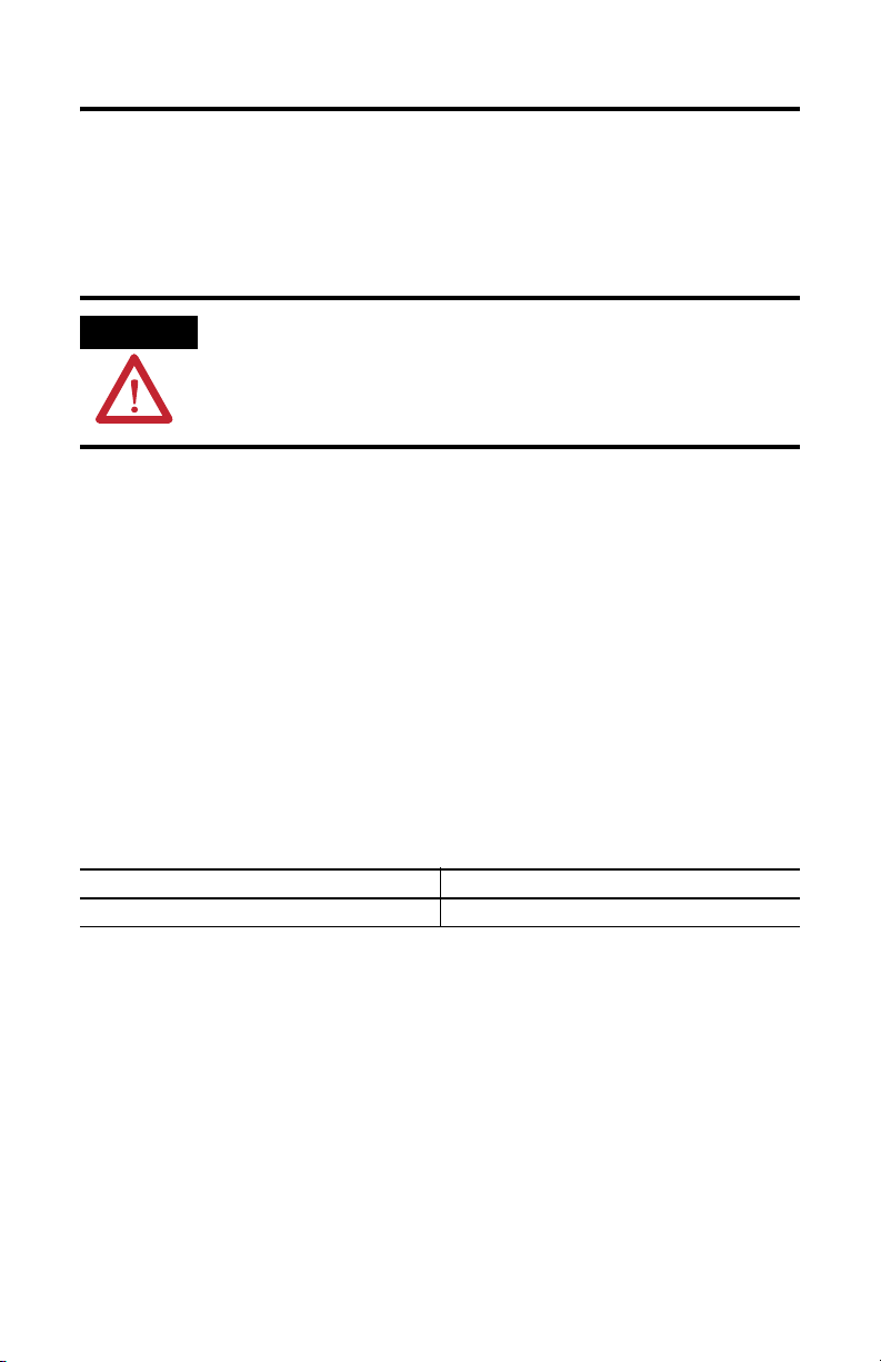
Terminal Wiring
The thermocouple module contains a green, 18-position, removable terminal block.
The terminal pin-out is shown below.
ATTENTION
Disconnect power to the SLC before attempting to install,
remove, or wire the removable terminal wiring block.
(Terminal Block Spare Part Catalog Number 1746-RT32)
CJC Assembly
Shield
Shield
Shield
Shield
Shield
CJC Assembly
Release Screw Max. Torque =
0.7 to 0.9 Nm (6 to 8 in-lb)
CJC A+
CJC A-
CJC B+
CJC B-
Release Screw Max. Torque =
0.7 to 0.9 Nm (6 to 8 in-lb)
Channel 0+
Channel 0-
Channel 1+
Channel 1-
Channel 2+
Channel 2-
Channel 3+
Channel 3-
Analog Common
(1)
below]
[see
(1) Replacing a Series A thermocouple module with a Series B module requires that the bottom right terminal (which was
SHIELD on Series A modules) no longer be connected to CHASSIS GROUND if it was previously. Use one of the other
SHIELD terminals.
Terminal screws accept a maximum of two #14 AWG (2 mm
2
) wires. Tighten
terminal screws only tight enough to immobilize wires. Maximum torque on
terminal screws is 0.7 to 0.9 Nm (6 to 8 in-lbs).
Publication 1746-IN010D-EN-P - June 2004
Page 12

12 SLC™ 500 4-Channel Thermocouple/mV Input Module
Thermocouple Junctions
There are three types of thermocouple junctions:
• Grounded Junction - The measuring junction is physically connected to the
protective metal sheath providing electrical continuity between junction and
sheath.
• Ungrounded Junction - The measuring junction is electrically isolated from
the protective metal sheath. (Also called Insulated Junction.)
• Exposed Junction - Does not have a protective metal sheath so the
measuring junction is exposed.
The illustration that follows shows each of the three thermocouple types.
Extension Wire
Metal Sheath
Measuring Junction is isolated from sheath.
Measuring Junction has no sheath.
Measuring Junction is connected to sheath.
Grounded Junction
Ungrounded (Insulated)
Junction
Exposed Junction
Publication 1746-IN010D-EN-P - June 2004
Page 13

Wiring Considerations
SLC™ 500 4-Channel Thermocouple/mV Input Module 13
ATTENTION
Follow the guidelines below when planning your system wiring.
• To limit noise, keep thermocouple and millivolt signal wires as far away as
possible from power and load lines.
• To ensure proper operation and high immunity to electrical noise, always
use Belden™ 8761 (shielded, twisted-pair) or equivalent wire for millivolt
sensors or shielded, twisted-pair thermocouple extension lead wire specified
by the thermocouple manufacturer for the thermocouple type you are using.
Using the incorrect thermocouple extension wire type or not following the
correct polarity convention will cause invalid readings.
• Special considerations for using the analog common (ANALOG COM)
terminal based on thermocouple type:
(See page 12 for an explanation of thermocouple junctions.)
– When using grounded thermocouple(s), jumper the ANALOG COM
terminal to any single active grounded channel’s plus (+) or minus (-)
terminal.
– When using exposed thermocouple(s) that have the thermocouple
junction touching an electrically conductive material, jumper the
ANALOG COM terminal to any single active exposed channel’s plus (+)
or minus (-) terminal.
– When using ungrounded (shielded) or exposed thermocouples that are
not touching an electrically conductive material, do not use the
ANALOG COM terminal.
– When using a mix of grounded, ungrounded, and exposed
thermocouples, jumper the ANALOG COM terminal to any single active
grounded channel’s plus (+) or minus (-) terminal.
The possibility exists that grounded or exposed thermocouples
can become shorted to a potential greater than that of the
thermocouple itself. Due to possible shock hazard, care should
be taken when wiring these types of thermocouples. See
page 12 for definitions of thermocouple junctions.
Publication 1746-IN010D-EN-P - June 2004
Page 14

14 SLC™ 500 4-Channel Thermocouple/mV Input Module
– If millivolt inputs are used, the terminal should be biased to a level
within 2V of the signal of interest. Use 10KΩ resistors to create a resistive
voltage divider as shown in the following circuit diagram.
TIP
The Series A 1746-NT4 does not have an ANALOG COM
terminal and cannot be used with multiple grounded and/or
exposed thermocouples that touch electrically conductive
material. The Series A can be used with a single grounded
and/or exposed thermocouple that touches electrically
conductive material, or multiple grounded thermocouples that
have the protective sheath made of an electrically
non-conductive material such as ceramic.
+
NT4
Strain Gauge
Bridge
Input
(CHL 0, CHL 1, CHL
2, CHL 3)
Analog Com
+
-
fixed
fixed
Vcc
variable
fixed
10K Ω
10K Ω
• Ground the shield drain wire at one end only. The preferred location is to
the same point as the sensor ground reference.
– For grounded thermocouples or mV sensors, this is at the sensor.
– For insulated/ungrounded thermocouples, this is at the module.
– Refer to IEEE Std. 518, Section 6.4.2.7 or contact your sensor
manufacturer for additional details.
• If it is necessary to connect the shield at the module, each input channel has
a convenient shield connection screw terminal that provides a connection to
chassis ground. All shields are internally connected, so any shield terminal
can be used with channels 0-3. For maximum noise reduction, one shield
terminal must be connected to earth ground potential, i.e. mounting bolt on
1746 chassis.
Publication 1746-IN010D-EN-P - June 2004
Page 15

SLC™ 500 4-Channel Thermocouple/mV Input Module 15
• Tighten terminal screws using a flat or cross-head screwdriver. Each screw
should be turned tight enough to immobilize the wire’s end. Excessive
tightening can strip the terminal screw. The torque applied to each screw
should not exceed 6 - 8 in-lbs (0.7 - 0.9 Nm) for each terminal.
• The open thermocouple detection circuit injects approximately
12 nanoAmperes into the thermocouple cable. A total lead resistance of
25 Ω (12.5 one-way) will produce 0.3 mV of error. To reduce error, use large
gauge wire with less resistance for long wire runs.
• Follow system grounding and wiring guidelines found in your SLC 500
Installation and Operation Manual, publication number 1747-6.21 (Fixed
Hardware Style) or 1747-UM011 (Modular Hardware Style).
Wiring Input Devices to the NT4
After the thermocouple module is properly installed in the chassis, follow the
wiring procedure below using the proper thermocouple extension cable, or
Belden 8761 for non-thermocouple applications.
Signal Wire
Signal Wire
Cable
Drain Wire
(Twist together, shrink wrap, and
connect to earth ground.)
Foil Shield
(Cut foil shield and
drain wire; then
insulate at cable
end.)
Signal Wire
Signal Wire
To wire your NT4 module, follow these steps.
1. At each end of the cable, strip some casing to expose the individual wires.
2. Trim the signal wires to 2-inch lengths. Strip about 4.76 mm (3/16 inch) of
insulation away to expose the end of the wire.
3. At one end of the cable, twist the drain wire and foil shield together, bend
them away from the cable, and apply shrink wrap. Then earth ground at the
preferred location based on the type of sensor you are using (see wiring
guidelines on page 13).
Publication 1746-IN010D-EN-P - June 2004
Page 16

16 SLC™ 500 4-Channel Thermocouple/mV Input Module
4. At the other end of the cable, cut the drain wire and foil shield back to the
cable and apply shrink wrap.
5. Connect the signal wires to the NT4 terminal block and the input.
6. Repeat steps 1 through 5 for each channel on the NT4 module.
Cold-Junction Compensation (CJC)
ATTENTION
Do not remove or loosen the cold junction compensating
thermistor assemblies located between the two upper and
lower CJC terminals on the terminal block. Both thermistor
assemblies are critical to ensure accurate thermocouple input
readings at each channel. The module will not operate in the
thermocouple mode if either assembly is removed.
To obtain accurate readings from each of the channels, the cold-junction
temperature (temperature at the module’s terminal junction between the
thermocouple wire and the input channel) must be compensated for. Two coldjunction compensating thermistors have been integrated in the removable terminal
block; they must remain installed to retain accuracy.
In case of accidental removal of either or both of the thermistor assemblies, make
sure to replace them by connecting each one across the CJC terminals located at the
top and bottom left side of the terminal block. When connecting the thermistor
assembly at the top of the terminal block (between terminals CJC A+ and CJC A-),
the lug containing the thermistor (marked with red epoxy) should attach to the
uppermost screw terminal (CJC A+). When connecting the thermistor assembly at
the bottom of the terminal block (between terminals CJC B+ and CJC B-), the lug
containing the thermistor should attach to the lowermost screw terminal (CJC B+).
CJC
Assembly
Thermistor
(Always attach red lug to
the CJC+ terminal.)
Bottom of Terminal Block
Publication 1746-IN010D-EN-P - June 2004
Page 17

SLC™ 500 4-Channel Thermocouple/mV Input Module 17
Module Addressing
The following memory map shows you how the output and input image tables are
defined for the thermocouple module.
SLC 5/0X
Data Files
Slot e
Output Image
Slot e
Input Image
Output
Scan
Input
Scan
Thermocouple
Module Image
Output Image
8 Words
Input Image
8 Words
(Class 1)
Bit 15 Bit 0
Channel 0 Configuration Word
Channel 1 Configuration Word
Channel 2 Configuration Word
Channel 3 Configuration Word
Output
Image
Input
Image
Bit 15 Bit 0
Words 4-7
(not defined)
Channel 0 Data Word
Channel 1 Data Word
Channel 2 Data Word
Channel 3 Data Word
Channel 0 Status Word
Channel 1 Status Word
Channel 2 Status Word
Channel 3 status Word
Word 0
Word 1
Word 2
Word 3
Word 0
Word 1
Word 2
Word 3
Word 4
Word 5
Word 6
Word 7
Address
O:e.0
O:e.1
O:e.2
O:e.3
Address
I:e.0
I:e.1
I:e.2
I:e.3
I:e.4
I:e.5
I:e.6
I:e.7
Channel Configuration
Once the module is installed, each channel on the module can be configured to
establish the way the channel will operate. You configure the channel by entering
bit values into the configuration word using your programming software. Channels
0 through 3 on the NT4 are configured by entering bit values into output words 0
through 3 respectively. Output words 4 through 7 are not used. See the table on
page 18 for bit settings.
Publication 1746-IN010D-EN-P - June 2004
Page 18

18 SLC™ 500 4-Channel Thermocouple/mV Input Module
Channel Configuration Word - Bit Definitions
Define To Select
Make these bit settings in the Channel Configuration Word
(2)
15–12
11109876543210
Input type Thermocouple Type J
Thermocouple Type K
Thermocouple Type T
Thermocouple Type E
Thermocouple Type R
Thermocouple Type S
Thermocouple Type B
Thermocouple Type N
±50mV
±100mV
CJC temperature
Data format
Engineering units 1
Engineering units 10
Scaled-for-PID 10
Proportional Counts 11
(3)
(4)
Not Used
Open circuit Zero 00
Upscale 01
Downscale 10
Temperature
units
Channel
filter
frequency
Degrees C
Degrees F
10 Hz
50 Hz 01
60 Hz 10
(5)
(5)
0
1
00
250 Hz 11
Channel
enable
(1) Bit settings other than those shown in the table are invalid.
(2) Ensure unused bits 12-15 are always set to zeros.
(3) For engineering units x 1, values are expressed in 0.1 degrees or 0.01 mV.
(4) For engineering units x 10, values are expressed in 1.0 degrees or 0.1 mV.
(5) When millivolt input type is selected, the bit setting for temperature units is ignored.
Channel Disabled 0
Channel Enabled 1
(1)
0000
0001
0010
0011
0100
0101
0110
0111
1000
1001
1111
00
01
Publication 1746-IN010D-EN-P - June 2004
Page 19

SLC™ 500 4-Channel Thermocouple/mV Input Module 19
Specifications
Electrical Specifications
Backplane Current Consumption 60 mA at 5V dc
40 mA at 24V dc
Backplane Power Consumption 1.3W maximum (0.3W at 5V dc, 1.0W at 24V dc)
Number of Channels 4 (backplane isolated)
I/O Chassis Location Any I/O module slot except slot 0
A/D Conversion Method Sigma-Delta Modulation
Input Filtering Low pass digital filter with programmable notch (filter) frequencies
Normal Mode Rejection (between
[+] input and [-] input)
Common Mode Rejection
(between inputs and chassis
ground)
Input Filter Cut-Off Frequencies 2.62 Hz at 10 Hz filter frequency
Calibration Module autocalibrates at powerup and whenever a channel is enabled.
Isolation 500V dc one minute between inputs and chassis ground, and between
Maximum Channel-to-Channel
Common-Mode Separation
Greater than 100 dB at 50 Hz (10 Hz, 50 Hz filter frequencies)
Greater than 100 dB at 60 Hz (10 Hz, 60 Hz filter frequencies)
Greater than 150 dB at 50 Hz (10 Hz, 50 Hz filter frequencies)
Greater than 150 dB at 60 Hz (10 Hz, 60 Hz filter frequencies)
13.1 Hz at 50 Hz filter frequency
15.72 Hz at 60 Hz filter frequency
65.5 Hz at 250 Hz filter frequency
inputs and backplane.
Series B or later: 2V maximum between any two channels
Series A: 0V separation
Publication 1746-IN010D-EN-P - June 2004
Page 20

20 SLC™ 500 4-Channel Thermocouple/mV Input Module
Physical Specifications
LED Indicators 5 green status indicators, one for each of 4 channels and one for module
Module ID Code 3510
Recommended Cable:
for thermocouple inputs
for mV inputs Belden #8761 or equivalent
Maximum Wire Size Two 14 AWG wires per terminal
Maximum Cable Impedance 25 ohms maximum loop impedance, for <1LSB error
Removable Terminal Strip Allen-Bradley spare part Catalog Number 1746-RT32
(1) Refer to the thermocouple manufacturer for the correct extension wire.
status
Appropriate shielded, twisted-pair thermocouple extension wire
(1)
Environmental Specifications
Operating Temperature
Storage Temperature -40°C to +85°C (-40°F to +185°F)
Relative Humidity 5% to 95% (without condensation)
Certification UL listed
(1) When the NT4 module detects zero degrees (+/- 3°) at the CJC, it will detect an out of range condition and set values to
downscale -270°C (-454°F). It is recommended that ambient temperature surrounding the SLC 500 system be maintained
above 3°C (37.4°F) in order for the NT4 module to measure temperature correctly without detecting an out of range
condition.
0°C to +60°C (+32°F to +140°F)
CSA approved
Class I, Division 2, Groups A, B, C, D
CE compliant for all applicable directives when product or packaging is marked
(1)
Publication 1746-IN010D-EN-P - June 2004
Page 21

SLC™ 500 4-Channel Thermocouple/mV Input Module 21
Thermocouple Temperature and Millivolt Input Ranges
Input Type Temperature Range
Thermocouple Type J -210°C to +760°C (-346°F to +1400°F)
Thermocouple Type K -270°C to +1370°C (-454°F to +2498°F)
Thermocouple Type T -270°C to +400°C (-454°F to +752°F)
Thermocouple Type E -270°C to +1000°C (-454°F to +1832°F)
Thermocouple Type R 0°C to +1768°C (+32°F to +3214°F)
Thermocouple Type S 0°C to +1768°C (+32°F to +3214°F)
Thermocouple Type B +300°C to +1820°C (+572°F to +3308°F)
Thermocouple Type N 0°C to +1300°C (+32°F to +2372°F)
Millivolt Input: -50 mV dc to +50 mV dc
Millivolt Input: -100 mV dc to +100 mV dc
Input Specifications
Thermocouple Linearization IPTS-68 standard, NBS MN-125, NBS MN-161
Cold-Junction Compensation Accuracy ±1.5°C, 0°C to +85°C (+32°F to +185°F)
Input Impedance Greater than 10MΩ
Temperature Scale (Selectable) °C or °F and 0.1°C or 0.1°F
DC Millivolt Scale (Selectable) 0.1 mV or 0.01 mV
Open Circuit Detection Leakage Current 12 nA maximum
Open Circuit Detection Method Upscale
Module Update Time The sum of all enabled channel’s sample times plus one CJC
Channel Turn-On Time,
Reconfiguration Time
Channel Turn-Off Time Requires up to one module update time
Time to Detect Open Circuit 500 msec or 1 module update time, whichever is greater
update time. See channel sampling time table on page 22.
Requires up to one module update time plus one of the following:
• 250 Hz Filter = 82 milliseconds
• 60 Hz Filter = 196 milliseconds
• 50 Hz Filter = 226 milliseconds
• 10 Hz Filter = 946 milliseconds
Publication 1746-IN010D-EN-P - June 2004
Page 22

22 SLC™ 500 4-Channel Thermocouple/mV Input Module
Thermocouple/mV Input Module Accuracy
Input Type
J ±1.06°C ±1.91°F ±0.0193°C/°C, °F/°F
K ±1.72°C ±3.10°F ±0.0328°C/°C, °F/°F
T ±1.43°C ±2.57°F ±0.0202°C/°C, °F/°F
E ±0.72°C ±1.3°F ±0.0190°C/°C, °F/°F
S ±3.61°C ±6.5°F ±0.0530°C/°C, °F/°F
R ±3.59°C ±6.46°F ±0.0530°C/°C, °F/°F
B ±3.12°C ±5.62°F ±0.0457°C/°C, °F/°F
N ±1.39°C ±2.5°F ±0.0260°C/°C, °F/°F
±50 mV ±50 µV ±50 µV ±1.0 µV/°C, ±1.8 µV/°F
±100 mV ±50 µV ±50 µV ±1.5 µV/°C, ±2.7 µV/°F
(1) Assumes the module terminal block temperature is stable.
With Autocalibration
Maximum Error at
+25°C
(1)
Maximum Error at
+77°F
Without Autocalibration
Temperature Drift
(0°C to +60°C)
Filter Frequency and Step Response Time
Filter Frequency
10 Hz 100 dB 100 dB 2.62 Hz 300 msec
50 Hz 100 dB - 13.1 Hz 60 msec
60 Hz - 100 dB 15.72 Hz 50 msec
250 Hz - - 65.5 Hz 12 msec
(1) Normal Mode Rejection
50 Hz NMR
(1)
60 Hz NMR
1
Cut-Off
Frequency
Step Response
(1)
Channel Sampling Time for Each Filter Frequency
CJC Update Time
14 msec 12 msec 50 msec 60 msec 300 msec
(1) all values ±1 msec
Channel Sampling Time
250 Hz Filter 60 Hz Filter 50 Hz Filter 10 Hz Filter
Publication 1746-IN010D-EN-P - June 2004
(1)
Page 23

SLC™ 500 4-Channel Thermocouple/mV Input Module 23
Publication 1746-IN010D-EN-P - June 2004
Page 24

Rockwell Automation Support
Rockwell Automation provides technical information on the Web to assist you in
using its products. At http://support.rockwellautomation.com
technical manuals, a knowledge base of FAQs, technical and application notes,
sample code and links to software service packs, and a MySupport feature that you
can customize to make the best use of these tools.
For an additional level of technical phone support for installation, configuration,
and troubleshooting, we offer TechConnect Support programs. For more
information, contact your local distributor or Rockwell Automation representative,
or visit http://support.rockwellautomation.com
.
Installation Assistance
If you experience a problem with a hardware module within the first 24 hours of
installation, please review the information that's contained in this manual. You can
also contact a special Customer Support number for initial help in getting your
module up and running.
, you can find
United States 1.440.646.3223
Outside United
States
Monday – Friday, 8am – 5pm EST
Please contact your local Rockwell Automation representative for any
technical support issues.
New Product Satisfaction Return
Rockwell tests all of its products to ensure that they are fully operational when
shipped from the manufacturing facility. However, if your product is not
functioning, it may need to be returned.
United States Contact your distributor. You must provide a Customer Support case number
Outside United
States
Rockwell Automation, Allen-Bradley, SLC, and TechConnect are trademarks of Rockwell Automation, Inc.
Trademarks not belonging to Rockwell Automation are property of their respective companies.
Publication 1746-IN010D-EN-P - June 2004 PN 40071-139-01(4)
Supersedes Pub lication 1746-IN010C-EN -P - November 2002 Copyright © 20 07 Rockwell Automation , Inc. All rights reserv ed. Printed in Singapore.
(see phone number above to obtain one) to your distributor in order to
complete the return process.
Please contact your local Rockwell Automation representative for return
procedure.
 Loading...