

Page 1
Installation Instructions
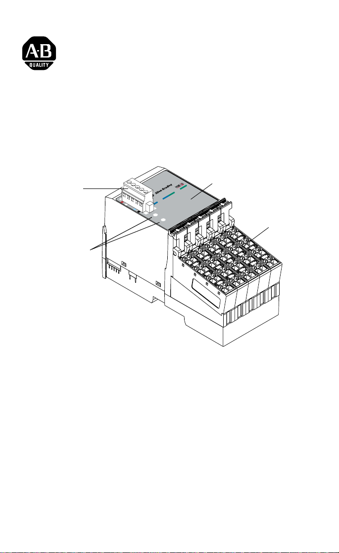
POINTBlock dc 16 Input Module
(Cat. No. 1734D-IB16 and -IB16S)
I/O Status
DeviceNet
Connector
DeviceNet Node
Setting Switc h es
(1s and 10s)
Module
Status
Network
Status
Outputs
0
1
4
Inputs
5
0
6
1
2
9
-
3
0
3
6
-
0
1
Indicators
4
5
6
7
2
3
7
Remote
Termination
Blocks
This 1734D input module is a DIN-rail mounted device with an
integrated DeviceNet communication interface, 16 inputs, removable
termination s, and a PointBus expansion port. The expansion port
allows you to add up to a maximum of 12 additional POIN T I/O
modules.
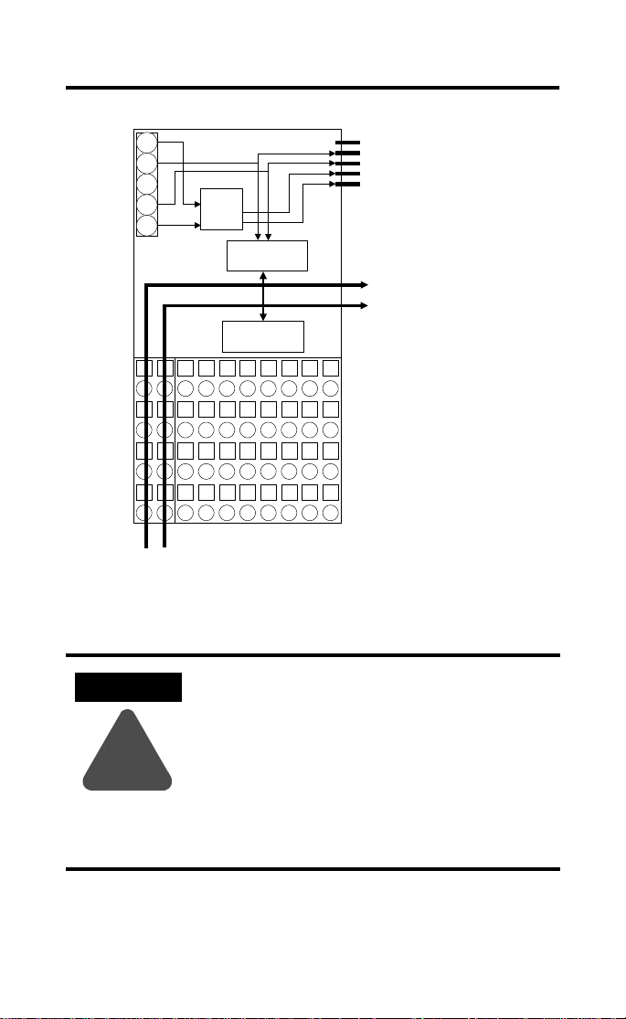
The module includes a non-isola ted DeviceNet communication
interface. The 24V dc from the DeviceNet connection powers a
non-isolated dc/dc converter that generates +5V dc which powers the
POINTBlock electronics and connects to the PointBus port to power
the expansion I/O electronics.
The 1734D-IB16 uses cage- clamp terminations, and the 1734D-IB16S
uses spring-clamp terminations.
POINTBlock and POINT I/O are trademarks
of Rockwell Automation1 Publication 1734D-IN002A-EN-P - April 2001
Page 2
2 POINTBlock dc 16 Input Module
Simplified Schematic of POINTBlock
24
DeviceNet
Connector
CH
SH
CL
RT
24V
to 5V
Microprocessor
I/O Circuits
En
CH
PointBus Expansion Port
CL
5V
(allows expansion of up to
GND
12 POINT I/O modules)
Field Bus
Connector
Power
I/O Connections
Connections
12/24V dc
ATTENTION
Whatever field power you supply is connected
to the internal field-power bus. For example, if
120V ac is applied to the power connections,
there will be 120V ac applied to the modules
through the internal fiel d-power bus.
!
POINT I/O modules to the right of this module
will have this internal power bus voltage
applied, unless you use a 1734-FPD to interrupt
and change the field power-bus voltage.
Publication 1734D-IN002A-EN-P - April 2001
41971
Page 3
POINTBlock dc 16 Input Modu le 3
ATTENTION
!
POINTBlock is designed to be grou nded through
the DIN rail to chassis ground. To assure proper
grounding of POINTBlock and POINT I/O
adapters and terminal bases to chassis ground, the
recommended DIN rail material is zinc-plated,
yellow-chromated steel. Mount POINTBlock,
POINT I/O adapters and terminal bases only to
zinc-plated, yellow-chromated steel.
Installing the POINTBlock 16 Input M odule
To install the 16 Input module on the DIN rail, proceed as follows:
1. Position the block module vertically above the DIN rail.
2. Press down firmly to install the module on the DIN rail. (The
locking mechanism will lock the module to the DIN rail.)
ATTENTION
Do not discard the end cap. Use this end cap to
cover the exposed interconnections on the last
mounting base/block module on the DIN rail.
Failure to do so could result in equipment
damage or injury from ele ctric shock.
!
If installing a replacement POINTBlock module to an existing system:
1. To remove the block module from the DIN rail, pull up on the
RTB removal handles to remove the terminal blocks.
2. Use a small bladed screwdriver to rotate the orange DIN rail
locking screw to a vertical position. This releases the locking
mechanism.
3. Lift straight up to remove.
4. Position the replacement block module vertically above the
DIN rail.
Publication 1734D-IN002A-EN-P - April 2001
Page 4

4 POINTBlock dc 16 Input Module
5. Slide the block module down allowing the interlocking side
pieces to engage the adjacent modu le/adapter.
6. Press firmly to seat the block module on the DIN rail. The
module locking mechanism will snap into place.
Setting the Node Address
Module Status
Network Status
I/O stat us
1’s Node Address Rotary Switch
42004
10’s Node Address Rotary Switch
To set the node address, set the combination of 1’s and 10’s to
correspond to the required a ddress. (For example, for 61, set the 10’s
switch to 6 and the 1’s switch to 1.)
Publication 1734D-IN002A-EN-P - April 2001
Page 5

Wiring the 16 dc Input Module
Field
Power
POINTBlock dc 16 Input Modu le 5
Inputs
12/24V dc
Power
V dc
NC = No Connection Chas Gnd = Chassis Ground
C = Common V = Supply
Input Wiring
Sink Input
Prox
NC
NC
C
Vin
01
0
23
2
45
C
67
V
01
NC
23
NC
45
C
67
Vin
RTB0 RTB1 RTB2 RTB3 RTB4
1
3
C
V
01
4
23
6
45
C
67
V
5
7
C
V
01
8
23
10
45
C
67
V
9
11
C
V
01
12
23
14
45
C
67
V
This supply will be connected to the internal power bus.
RTB 1
01
In 0 In 1
3-wire2-wire
2
In 2
4
C
6
VV
In 3
C
3
Prox ProxProx
5
7
13
15
C
V
42064
V = 12/24V dc
C = Common
Publication 1734D-IN002A-EN-P - April 2001
Repeat for RTB 2, RTB 3 and RTB 4.
41967
Page 6

6 POINTBlock dc 16 Input Module
Channel Input Terminal Common Voltage
Remote Termination Block 0
Field Power Block No connections to terminals 0, 1, 2 and 3
Vin (12/24V dc) 6 and 7
Common 4 and 5
Remote Termination Block 1
0046
1157
2246
3357
Remote Termination Block 2
4046
5157
6246
7357
Remote Termination Block 3
8046
9157
10 2 4 6
11 3 5 7
Remote Termination Block 4
12 0 4 6
13 1 5 7
14 2 4 6
15 3 5 7
Connect common on 3-wire proximity switches.
12/24V dc is supplied through the internal power bus.
Note: When connecting more than 1 wire in a termination point,
make sure that both wires are the same gauge and type.
Publication 1734D-IN002A-EN-P - April 2001
Page 7

POINTBlock dc 16 Input Modu le 7
DeviceNet Connector Wiring
+V
CAN - High
Shield
CAN - Low
-V
42132
DeviceNet
connection
Red
White
Bare
Blue
Black
Communicating with Your Module
I/O messages are sent to (consum ed) and received from (produced)
the POINTBlock I/O modules. These messages are mapped into the
processor’s memory. This POINTBlock I/O input module produces 2
bytes of input data (scanner Rx). It does not consume I/O data
(scanner Tx).
Default Data for the 1734D-IB16
1514131211109876543210
Produces
Consumes
Where: I0 = channel 0, I 1 = channel 1; 0 = off, 1 = on
I15 I14 I13 I12 I11 I10 I9 I8 I7 I6 I5 I4 I3 I2 I1 I0
(Rx)
(Tx)
No consumed data
Publication 1734D-IN002A-EN-P - April 2001
Page 8

8 POINTBlock dc 16 Input Module
e
Safety Approvals
C-UL and UL Hazardous Location Approval
C-UL and UL certifies products for general use as well as for use in
hazardous locations. Actual C-UL and UL certification is ind icated
by the product label as shown below, and not by statements in any
user documentation.
Example of the C-UL
and UL certification
product label:
CUS
CL I, DIV 2
GP A,B,C,D
TEMP
Approbation d’utilisation dans des
environnements dangereux par la C-UL and UL
La C-UL and UL certifie des produits pour une utilisation générale aussi
bien que pour une utilisation en environnements dangereux. La
certification C-UL and UL en vigueur est indiquée par l'étiquette produit
et non par des indications dans la documentation utilisateur.
Exemple d'étiquette de
certification d'un
produit par la C-UL and
UL :
LISTED
To comply with C-UL and UL certification for use in hazardous locations,
the following information becomes a part of the product literature for
this C-UL and U L-certified industrial constrol product.
• This equipment is suitable for use in Class I, Division 2, Groups
A, B, C, D, or non-hazardous locations only.
• The products having the appropriate C-UL and UL markings
(that is, Class I, Division 2, Groups A, B, C, D) are certified for
use in other equipment where the suitability of combination
(that is, application or use) is determined by the C-UL and UL or
the local inspection office having jurisdiction
• Peripheral equipment must be suitable for the location in
which it is used.
Important: Due to the modular nature of a programmable control
system, the produ ct with the highest temperature rating
determines the overall temperature code rating of a
programmable control system in a Class I, Division 2,
location. The temperature c ode rating is marked on the
product label as shown.
Temperature code rating: Code de températ ur e :
CL I, DIV 2
GP A,B,C,D
TEMP
CUS
LISTED
The followin g warnin gs apply to produc ts havi ng C-UL an d UL certi fica tion
for use in hazardous locations.
WARNING: Explosion Hazard
• Substitution of components may impair suitability for Class I,
Division 2.
• Do not replace components unless power has been switched
off or the area is known to be non-hazardous.
• Do not disconnect equipment unless power has been switched
off or the area is known to be non-hazardous.
• Do not disconnect connectors unless power has been switched
off or the area is known to be non-hazardous. Secure any
user-supplied connectors that mate to external circuits on this
equipment by using screws, sliding latches, threaded
connectors, or other means such that any connection can
withstand a 15 Newton (3.4 lb.) separating force applied for a
minimum of one minute.
• Batteries must only be changed in an area known to be
non-hazardous.
C-UL and UL logo is a registered trademark of the Underwriters
Laboratories.
Look for temperature code rating her
EPour satisfaire à la certification C-UL and UL en environnements
dangereux, les informations suivantes font partie intégrante de la
documentation des produits de commande industrielle certifiés.
• Cet équipement ne convient qu’à une utilisation dans
des environnements de Classe I, Division 2,
Groupes A, B, C, D ou non dangereux.
• Les produits portant le marquage C-UL and UL approprié
(c'est-à-dire Classe I, Division 2, Groupes A, B, C, D) sont certifiés
pour une utilisation avec d'autres équipements, les combinaisons
d’applications et d’ut ilisa ti on étan t dé te rmin ées par la C-UL and
UL ou le bureau local d'inspection.
• L'équipement périphérique doit convenir à l'emplacement
d'utilisation.
Important: De par la nature modulaire des systèmes de commande
programmables, le produit ayant le cod e de température le plus
élevé détermine le code de température global du système
dans un environnement de Classe I, Division 2. Le code de
température est indiqué sur l'étiquette produit.
CUS
LISTED
Les avertissements suivants s'appliquent aux produits ayant la certification
C-UL and UL pour une utilisation dans des environnements dangereux.
AVERTISSEMENT : Risque d'explosion
• La substitution de composants peut rendre ce matériel inadapté à
une utilisation en environnement de
Classe I, Division 2.
• Couper le courant ou s'assurer que l’environnement est classé non
dangereux avant de remplacer des composants.
• Couper le courant ou s’assurer que l’environnement est classé non
dangereux avant de débrancher l'équipement.
• Couper le courant ou s'assurer que l’environnement est classé non
dangereux avant de débrancher les connecteurs. Fixer tous les
connecteurs fournis par l'utilisateur pour se brancher aux circuits
externes de cet appareil à l 'aide de vis, loquets coulissants,
connecteurs filetés ou autres, de sorte que les connexions résistent
à une force de séparation de 15 Newtons (1,5 kg - 3,4 lb.) appliquée
pendant au moins une minute.
• S'assurer que l'environnement est classé non dangereux avant de
changer les piles.
Le sigle C-UL and UL est une marque déposée de la Underwriters
Laboratories.
CL I, DIV 2
CUS
GP A,B,C,D
TEMP
LISTED
CL I, DIV 2
GP A,B,C,D
TEMP
Le code de température est indiqué ici.
Publication 1734D-IN002A-EN-P - April 2001
Page 9

POINTBlock dc 16 Input Modu le 9
Specification s
Specifications - 1734D-IB16, -IB16S
Input Specifications - IEC 3+ 24V dc Input Compliant
Number of Channels 16 input channels
ON-State Voltage Range 10V dc min
ON-State Current 2.5mA min
OFF-State Voltage 5V dc max
OFF-State Cu r r e nt 1.5mA min
Input Impedance 4.7K Ω max (3.6K Ω nominal)
Input Filter Time
OFF to ON
ON to OFF
General Specification s
Pointbus Output Current 1A max @ 5V dc output power
DeviceNet Current 95mA maximum for POINTBlock
Number of POINT I/O
Expansion Modules
Isolation Voltage 850V dc for 1s between user power and Devi ceN et
Indicators 1 red/ green module status indicator
Power Dissipation 2.0W maximum @ 24V dc
Power Consumption 8.2W maximum @ 24V dc
Field Power Bus
Supply Voltage
Voltage Range
Supply Current
Dimensions Inches
(Millimeters)
24V dc nominal
28.8V dc max
6.3mA nominal @ 24V dc
7.6mA max
0.5ms hardware + (0 - 65ms selectable)
0.5ms hardware + (0 - 65ms selectable)
350mA for maximum with expansion of
12 POINT I/O modules
12 maximum at expansion port
1 red/green network status indicator
16 yellow I/O status indicators
24V dc nominal
10-28.8V dc
10A max
3.00H x 2.36W x 5.25L
(76.2 Hx 60.0W x 133.4L)
Publication 1734D-IN002A-EN-P - April 2001
Page 10

Environmental Conditi ons
Operational Temperature
Storage Temperature
Relative Humidity
Shock Operating
Non-operating
Vibration
Conductors Wire Size
-20 to +55
-40 to 85
5 to 95% noncondensing
30g peak acceleration, 11(±1)ms pulse width
50g peak acceleration, 11(±1)ms pulse width
Tested 5g @ 10-500Hz per IEC 68-2-6
14 AWG (2.5 mm
o
C (-4 to +131oF)
o
C (-40 to 185oF)
2
) - 22 AW G (0 .25m m2) solid or stranded
copper rated @ 75°C or greater
3/64 inch (1.2mm) insulation ma x
Category
Terminal Base Screw
1
2
7 pound-inches (0.6 Nm)
Torque
Field Wiring Terminations
DeviceNet
1 - Black Wire -V
2 - Blue Wire CAN Low
3 - Bare Wire Drain
4 - White Wire CAN High
5 - Red Wire +V
Field Power Supply 0 - No Connection 1 - No Connection
2 - No Connection 3 - No Connection
4 - Common 5 - Common
6 - Supply 7 - Supply
Mass 12.02 oz/340.77 grams
Agency Certification
(when product is marked)
• C-UL Listed
• C-UL Class I, Division 2 Groups A, B, C and D certified
• UL listed
• UL Class I, Division 2 Groups A, B, C and D certified
• CE marked for all applicable directives
• C-Tick marked for all applicable acts
1 Use this conductor category information for planning conductor routing. Refer to publication 1770- 4.1,
“Industrial Automation Wiring and Grounding Guidelines.”
Publication 1734D-IN002A-EN-P - April 2001 PN 957464-54
© 2001 Rockwell International Corporation. Printed in USA
 Loading...