


Dual Technology Industrial Detector Detector Industrial de Doble Tecnología Detector Industrial de Tecnologia Dupla
Model: RK325DT
Installation Instructions - Relay & BUS Modes Instrucciones de Instalación - Modos Relé y BUS Instruções de Instalação - Modos Relé & BUS
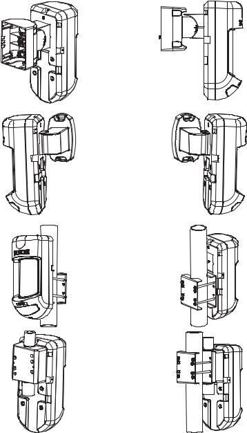

Table of Contents |
|
Relay Mode Installation ........................................................................ |
2 |
Introduction ............................................................................................. |
2 |
Mounting ................................................................................................. |
2 |
Mounting Considerations........................................................................ |
2 |
Wall Mount Installation............................................................................ |
3 |
Flat Mounting .......................................................................................... |
3 |
45° angle Mounting (Left side mounting)................................................ |
3 |
Changing Back Tamper position ............................................................ |
4 |
Terminal Wiring .............................................................................................. |
4 |
DIP Switch Settings.......................................................................................... |
5 |
Microwave Adjustment ................................................................................... |
5 |
Walk test .......................................................................................................... |
5 |
LEDs Display .................................................................................................... |
6 |
Relay Mode / BUS Mode Jumper................................................................... |
6 |
TRIPLE EOL Jumpers........................................................................................ |
7 |
Standard Swivel Installation .......................................................................... |
8 |
Wall Mounting ......................................................................................... |
8 |
Swivel Conduit Mounting ........................................................................ |
8 |
Replacing Lenses ........................................................................................... |
11 |
Lens Types ........................................................................................... |
12 |
Technical Specification.................................................................................. |
14 |
Ordering Information ................................................................................... |
14 |
UL Compliance Section................................................................................. |
14 |
BUS Mode Installation ........................................................................ |
15 |
Introduction.................................................................................................... |
15 |
Terminal Wiring ............................................................................................ |
15 |
Cover and Back Tamper....................................................................... |
15 |
Cover Tamper Only .............................................................................. |
15 |
Cover Tamper to Zone Input ................................................................ |
15 |
DIP Switch Settings........................................................................................ |
16 |
ProSYS Programming (from ProSYS software version 7.xx and above).. |
16 |
Adding / Deleting the WatchIN DT........................................................ |
16 |
Configuring the WatchIN DT Parameters............................................. |
17 |
System Parameters........................................................................................ |
19 |
WatchIN Installation Manual |
1 |
Relay Mode Installation
Introduction
RISCO Group's Dual Technology Grade 3 Industrial detector, WatchIN, is a unique detector with signal processing based on two Passive Infrared (PIR) channels and two Microwave (MW) channels. The detector can operate as a regular relay detector connected to any control panel, or as a BUS accessory when connected to RISCO Group's ProSYS control panel via the RS485 BUS, thus having unique remote control and diagnostic capabilities.
The instructions describe herein, describe the WatchIN in Relay & BUS mode. For detailed information regarding BUS mode installation, refer to BUS Mode installation chapter, page 15.
Mounting
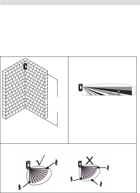
Mounting Considerations
Typical Height: 2.4m (7'10")
Default Lens: Wide angle 25m (88') 90° (RL325)
2.4m
(7'10")
25m (88')
WatchIN Detector -
 Optional Installation
Height:
2.4m – 3.7m
(7'10"-12'2")
For optimum detection, select a location that is likely to intercept an intruder moving across the coverage pattern at a 45° trajectory.
2 |
WatchIN Installation Manual |

Wall Mount Installation |
|
|
|
|
|
|
|
Figure 1 |
|
Figure 2 |
|
Note: |
|
|
|
|
|
|
|
|
|
|
I1 |
The installation knockouts numbering are marked on |
|
|
|
|
|
the back plate. |
|
|
|
|
|
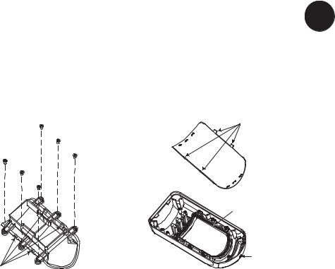
1. Open WatchIN front cover |
|
|
|
|
|
(unlock C1, Figure 1). |
|
|
|
|
|
2. Release internal base (unlock I1, Figure 2). |
|
|
|
|
|
3. Select mounting installation as follows: |
|
|
|
|
|
Flat Mounting: |
|
|
|
|
|
Open knockouts on external base (Figure 3). |
|
|
|
|
|
• B1 - B4: Wall mounting knockouts |
|
|
|
|
|
• T1: Back tamper knockout |
|
|
|
|
|
• W2 / W3: Wires entry knockouts |
|
|
|
|
|
45° angle Mounting (Left side |
|
|
|
|
|
|
|
|
C1 |
|
|
mounting): |
|
|
|
|
|
|
|
Figure 3 |
|
|
|
a. Open knockouts on external base |
|
|
|
|
|
|
|
|
T1 |
T6 |
T5 |
|
|
|
|
||
(Figure 3) |
|
|
|
|
|
• L1, L2: Left mounting knockouts |
|
T3 |
|
|
|
|
|
|
|
|
T4 |
• T3: Left tamper knockout |
|
L1 |
|
|
|
|
|
Tamper |
|
|
|
|
|
|
|
|
|
|
|
|
|
|
T2 |
• W5 / W6: Wire entry knockouts |
Lever |
|
|
|
|
|
|
B1 |
|
|
|
b. Remove tamper spring |
|
B |
|
|
|
|
|
|
R1 |
||
|
|
|
W5 |
|
|
c. Replace tamper bracket (Item 1) with |
|
|
|
(not visible) |
|
|
|
|
|
||
|
|
|
W6 |
|
B2 |
supplied flat tamper bracket (Item 2). |
|
|
|
||
|
|
|
|
||
Item 1 |
Item 2 |
|
|
|
|
|
|
A |
W3 |
|
W9 |
|
|
|
|
|
W2 |
d. Insert Tamper lever B onto T5 and T3 |
|
|
|
|
|
and secure screw A (Figure 3) |
|
|
|
R2 |
|
|
L2 |
|
|
||
|
|
|
|
|
(not visible) |
4. Insert external wires through external base |
|
|
|
|
|
|
|
|
|
|
B3 |
W2, W3 (Flat Mounting) or W5, W6 (Left |
|
B4 |
|
|
|
|
|
|
|
|
|
side mounting) (Figure 3). |
|
|
|
|
|
5. Secure external base to the wall. |
|
|
|
|
|
|
|
Figure 4 |
|
|
|
6. Insert external wires and tamper wires |
|
|
|
|
|
through internal base (Figure 4). |
|
|
|
|
|
7. Secure internal base to external base (lock |
|
|
|
|
|
I1, Figure 2). |
|
|
|
|
|
8. Close the front cover (Lock C1, Figure 1) |
|
|
|
|
|
after wiring and setting DIP switches. |
|
|
|
|
|
9. Walk test the detector. |
|
|
|
|
|
Note: |
|
|
|
|
|
For 45° right side installation use the equivalent units on the external base as follows:
Knockouts Description |
Left |
Right |
||
|
|
|
|
|
Mounting Knockouts |
L1, |
L2 |
R1, |
R2 |
Tamper spring knockouts |
T1, |
T3 |
T2, |
T4 |
Tamper screw anchor |
T5 |
T6 |
||
|
|
|
||
Wiring Knockouts |
W5, W6 |
W7, W8 |
||
|
|
|
|
|
WatchIN Installation Manual |
3 |

Changing Back Tamper position
The back tamper is by default secured on the right side of the internal base (Rear view). If you wish to move it to the left side (rear view), do the following (Figure 5):
1.Remove tamper screw 1 in order to release the tamper from position 7.
2.Ensure tamper spring 2 rests over tamper wire base 4.
3.Ensure plastic tamper bracket 3 rests over both 2 and 4.
4.Secure tamper screw 1 into 3 over position 6.
Figure 5
Left Side
Tamper
6
Right Side
Tamper
3 |
7 |
1
5
4
2
Notes:
1.Verify that you hear a "Click" when attaching the tamper spring to the wall.
2.For pole installation, the tamper can be moved to the bottom right-hand side of the internal base.
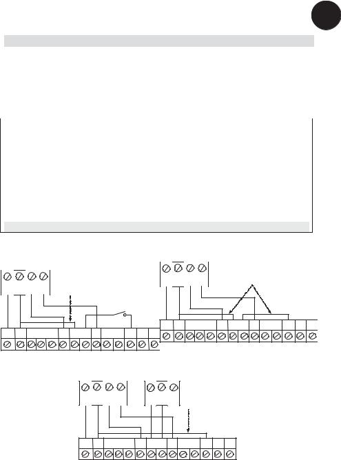
Terminal Wiring
12VDC
|
|
|
FREE |
|
FREE |
|
LED |
|
SET/ |
+ |
- |
N.O . COM N.C. |
(YEL) |
TAMPER |
(GRN) |
AM |
ENBL |
TEST |
UNSET |
|
|
N.O. N.C. |
|
N.C. |
|
N.C. |
|
|
|
WatchINPCB 
+,- |
12 VDC |
|
N.O |
Form C relay, 30VDC 1A |
|
|
NORMAL |
ALARM |
COM |
|
|
|
N.O COM N.C |
N.O COM N.C |
N.C
FREE YEL This terminal is a free pin that can be used to connect wires and EOL resistors
TAMPER N.C relay, 24VDC , 0.1A
FREE GRN This terminal is a free pin that can be used to connect wires and EOL resistors
AM Normally closed AM relay output (24VDC, 0.1A) indicates Anti Masking alarm or any trouble in the detector.
Note:
When a vibration detector is installed and DIP 8 is defined as Enabled this relay also opens momentarily when vibration event occurs.
LED ENBL Used to remotely control the LEDs when DIP 1 is set to ON. Enable: input is +12V OR no terminal connection
Disable: Connect the input to 0V
TEST Used to perform remote alarm testing to the detector by applying 0 volts to this terminal.
Success: Alarm relay is momentary opened Failure: AM relay is momentary opened
4 |
WatchIN Installation Manual |

SET/ |
|
This input enables to control Anti-masking and LEDs operation in accordance to |
|
|||
UNSET |
|
the system status, Set (Arm) / Unset (Disarm). |
|
|
|
|
|
|
While the system is armed, this feature prevents an intruder from gaining |
|
|||
|
|
knowledge of the detector’s status and disables Anti-masking detection. |
|
|||
|
|
|
|
|
|
|
|
|
System Status |
Input Status |
AM Relay |
LEDs |
|
|
|
Set (Arm) |
0V |
Off |
Off |
|
|
|
|
|
|
|
|
|
|
Unset (Disarm) |
12V or no connection |
On* |
On** |
|
|
|
|
|
|
|
|
|
|
* DIP 7 is ON (Anti masking enabled) |
|
|
|
|
|
|
** DIP 1 is ON (LEDs enabled) and LEDs ENABLE input terminal is enabled |
|
|||
|
|
(+12V OR no terminal connection) |
|
|
|
|
DIP Switch Settings
|
ON |
|
|
|
|
|
|
|
|
|
|
|
|
|
|
|
|
|
|
|
|
|
|
|
|
|
|
|
|
|
|
|
|
|
|
|
|
|
|
|
|
|
|
|
|
Factory |
|
|
|
|
|
|
|
|
|
|
|
|
|
|
|
|
|
|
|
|
|
|
|
Default |
|
|
|
|
|
|
|
|
|
|
|
|
|
|
|
|
|
|
|
|
|
|
|
||
|
|
|
|
|
|
|
|
|
|
|
|
|
|
|
|
|
|
|
|
|
|
||
|
1 |
2 |
3 |
4 |
5 |
|
6 |
|
7 |
8 |
9 |
|
10 |
|
|
||||||||
|
|
|
|
|
|
|
|
|
|
|
|
|
|
|
|
|
|
|
|
|
|
|
|
DIP 1: LEDs operation |
|
|
|
|
|
|
|
||||||||||||||||
|
|
|
|
|
On: LEDs Enabled |
|
|
|
|
||||||||||||||
|
|
|
|
|
Off: LEDs Disabled |
|
|
||||||||||||||||
DIP 2-3: Detection Sensitivity |
|
|
|||||||||||||||||||||
|
|
|
|
|
|
|
|
|
|
|
|||||||||||||
|
|
|
Sensitivity |
|
|
|
|
DIP2 |
DIP3 |
|
|||||||||||||
|
|
|
|
|
|
Low |
|
|
|
|
|
|
|
|
Off |
|
|
Off |
|
||||
|
|
|
|
|
|
Mid |
|
|
|
|
|
|
|
|
Off |
|
|
On |
|
||||
|
Normal (Default) |
|
|
|
On |
|
|
Off |
|
||||||||||||||
|
ACT(Anti-Cloak™ |
|
|
|
On |
|
|
On |
|
||||||||||||||
|
|
Technology) |
|
|
|
|
|
|
|
|
|
|
|
|
|||||||||
DIP 4: Alarm condition On: PIR or MW Off: PIR + MW
DIP 5: Detector's optics On: Barrier
Off: Wide angle DIP 6: Red LED /3 LED
On: Red LED only Off: 3 LEDs
DIP 7: Anti masking operation On: Enabled
Off: Disabled
DIP 8: Vibration detection (applicable to versions with Vibration sensor installed)
On: Enabled
Off: Disabled
DIP 9: Sway recognition Enable/Disable On: Enabled
Off: Disabled DIP 10: Green line
On: MW Off during Disarm (unset) Off: MW On during Disarm (unset)
Note:
Green line is valid when connecting wire from the panel output (arm follow) to the detector set/unset input.
Microwave Adjustment
Adjust Microwave coverage area by using the trimmer on the PCB.
MIN MAX
Walk test
Two minutes after applying power, walk test the protected area to verify proper operation.
For installations on uneven surfaces slide the PCB inside the internal base to the appropriate setting according to the desired height (2.4m, 3.0m, 3.7m) as printed on the bottom left corner of the PCB or use the standard swivel accessory.
For reducing the detection range, slide the PCB up or tilt the swivel down.
2.40M
3.00M
3.70M
WatchIN Installation Manual |
5 |

LEDs Display
|
LED |
State |
Description |
|
|
YELLOW |
Steady |
Indicates PIR detection |
|
|
|
Flashing |
Indicates AM (Anti mask) detection |
|
|
GREEN |
Steady |
Indicates MW detection |
|
|
|
|
|
|
|
|
|
|
|
|
RED |
Steady |
Indicates ALARM |
|
|
|
|
|
|
|
|
Flashing |
Indicates malfunctioned communication with ProSYS (BUS |
|
|
|
|
mode only) |
|
|
All LEDs |
Flashing (One after |
Unit initialization on power up |
|
|
|
|
|
|
|
|
another) |
|
|
|
|
|
|
|
|
|
|
|
|
|
Notes: |
|
|
|
|
|
|
|
|
1.DIP-Switch 1 should be in ON position to enable LED indications.
2.Only one LED is active at any one time. For example, in the case of both PIR and MW detection, either the steady YELLOW LED or the steady GREEN LED is displayed (the first to detect), followed by the Alarm RED LED.
|
Relay |
BUS |
Relay Mode / BUS Mode Jumper |
Mode |
Mode |
|
|
J-BUS jumper (located on the PCB between the red and green LEDs) is used to define the detector’s mode of operation as follows:
6 |
WatchIN Installation Manual |
TRIPLE EOL Jumpers
TRIPLE |
|
TAMPER EOL |
|
|
||||||||
EOL Jumpers |
|
|
|
|
|
|
|
|
|
|
|
|
|
|
|
|
|
|
|
|
|
|
|
|
|
|
|
|
|
|
|
|
|
|
|
|
|
|
|
|
|
|
|
|
|
|
|
|
|
|
J4 |
|
|
|
6.8K |
5.6K |
4.7K |
2.2K |
1K |
|||||
|
|
|
|
|
|
|
|
|
|
|
|
|
|
|
|
|
|
|
|
|
|
|
|
|
|
|
|
ALARM EOL |
|
|
|
J5 |
||||||
|
|
FAULT/AM EOL |
|
|
||||||||
|
J6 |
|
|
|
12K |
|
|
|
|
|||
|
|
|
|
|
|
|
|
|
||||
|
|
|
|
|
|
|
|
|
|
|||
|
J25 |
|
|
|
|
|
|
|
|
|||
|
|
|
SHORT |
|
|
|
|
|||||
|
|
|
|
|
|
|
||||||
|
|
AM/FAULT |
|
|
||||||||
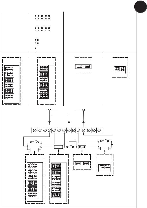
TAMPER EOL (J4) ALARM EOL (J5)
J4 |
J5 |
TAMPER EOL |
ALARM EOL |
JUMPERS |
JUMPERS |
6.8K |
6.8K |
5.6K |
5.6K |
4.7K |
4.7K |
2.2K |
2.2K |
1K |
1K |
No Resistor |
No Resistor |
|
|
(Factory Settings) |
(Factory Settings) |
|
Jumpers J4 and J5 allow the selection of Tamper and Alarm resistance (1K, 2.2K, 4.7K, 5.6K, 6.8K) according to the control panel (see Figure 6 below). Jumper J6 allows the selection of 12K for Fault/Anti-Mask.
Follow the terminal block connection diagram in Figure 6 when connecting the detector to a Double/Triple End Of Line (DEOL/TEOL) Zone.
Short AM/FAULT (J25) |
FAULT/AM EOL (J6) |
|
J25 |
|
J6 |
AM/FAULT |
FAULT/AM EOL |
|
|
|
JUMPERS |
Open |
Short |
|
|
|
12K |
|
|
Open Short |
PANEL TEOL
PANEL DEOL 

|
|
|
|
|
|
|
|
|
|
|
|
LED |
|
SET/ |
|
+ |
-- N.O. |
COM |
N.C. |
FREE |
|
TAMPER |
FREE |
AM |
TEST |
||||||
|
|
|
|
|
|
|
|||||||||
|
(YEL) |
|
|
|
(GRN) |
|
ENBL |
|
UNSET |
||||||
|
|
|
|
|
|
|
|
|
|
|
|
|
|
|
|
|
|
|
|
|
|
|
|
|
|
|
|
|
|
|
|
ALARM |
SHORT AM/FAULT |
FAULT/AM |
|
|
|
N.C. |
|
|
|
TAMPER |
|
J5 |
J4 |
J25 |
|
J6 |
ALARM EOL |
TAMPER EOL |
AM/FAULT |
FAULT/AM EOL |
|
JUMPERS |
JUMPERS |
|
|
JUMPERS |
6.8K |
6.8K |
|
|
|
|
|
|
|
|
|
|
Open |
Short |
|
|
|
|
|
12K |
5.6K |
5.6K |
|
|
|
|
|
|
|
Open Short |
4.7K |
4.7K |
|
|
|
2.2K |
2.2K |
|
|
|
1K |
1K |
|
|
|
No Resistor
No Resistor
(Factory Settings)
(Factory Settings)
Figure 6
WatchIN Installation Manual |
7 |

Standard Swivel Installation
The WatchIN detector package contains a standard swivel for flexible installation. Please follow the instructions below for mounting the detector with the Standard Swivel:
1.Open WatchIN front cover (Unlock C1, Figure1).
2.Release internal base (Unlock I1, Figure2).
3.Open knockouts on external base (Figure 7, Detail B)
•W1: Wires knockout
•S1,S2: Knockouts for securing external base to Standard Swivel
•S3: External base locking screw knockout
4.On the swivel accessory remove the required swivel cable wiring knockout S2, S7 or S9 (Figure 7, Detail A).
5.Remove back tamper from the internal base (see “Changing Back Tamper Position" paragraph) and connect it to S5 (Figure 7, Detail A) on the Standard Swivel.
Note:
Ensure that you see the engraved UP mark on the upper front face of the swivel.
6. Select the mounting installation type as follows:
Wall Mounting
a.Insert external cable wiring through knockouts S2, S7 or S9 and extract them (including the tamper wires) through the Swivel Wires Passage (Figure 7, Detail B).
b.Secure swivel to the wall through holes S1, S3, S6 and S8.
Note:
The CSMA is required when wall external wiring is used and protection pipe is required. The CSMA should be ordered separately - P/N RA300SC0000A.
Swivel Conduit Mounting (using optional Conduit Metal Swivel Adaptor – CSMA, Figure 7, Detail A)
Detail A |
|
|
Detail B |
Standard Swivel |
|
||
S1 |
S2 |
S3 |
|
|
|
|
Snaps |
|
|
CSMA |
Ø 16 mm |
|
|
|
|
|
|
|
|
|
|
|
W1 |
|
M1 |
|
|
|
|
|
|
|
|
|
S9 |
|
|
|
|
Tamper |
M2 |
|
|
|
|
|
|
|
|
|
|
|
|
S1 |
|
Spring |
|
|
|
|
|
|
S2 |
|
M3 |
|
|
|
|
S4 |
|
Holes |
|
S8 |
|
|
|
|
|
|
|
|
|
|
|
||
|
|
|
Ø 21 mm |
|
|
|
S3 |
|
|
|
|
|
|
|
|
|
M4 |
|
|
|
|
|
|
|
|
|
Swivel Wires |
|
|
S5 |
|
|
|
|
|
|
|
|
|
|
|
|
|
S7 |
S6 |
|
Detail C |
|
|
|
Passage |
Tamper |
|
||
|
|
|
|
|
|
||
|
|
|
|
|
|
|
|
|
|
|
|
|
|
(see Detail C) |
|
Figure 7
a.Choose the direction upon which to mount the CSMA according to the required diameter: 16mm (0.63 inches) or 21mm (0.83 inches).
b.Insert conduit to the CSMA.
c.Secure CSMA to the wall through points (M1, M4).
d.Insert external cables and tamper wires from the conduit through the swivel wires passage of the swivel (Figure 7, Detail A).
e.Secure swivel to the wall through holes S1, S3, S6 and S8.
8 |
WatchIN Installation Manual |
Note:
The Tamper spring S5 (Figure 7) should make contact with the wall through the tamper spring holes M2 or M3 on the CSMA. Make sure to hear the tamper "Click" when connecting to the wall.
7.Insert tamper wires and external cable wiring from Standard Swivel through knockout W1 on the external base (Figure 7, Detail B).
8.Connect the external base to the swivel using the dedicated snaps (Figure 8).
See Detail A
Snaps
External Base
W1
Swivel to External Base
Connecting Screws
S1
S2
Internal Base
S3
Detail A
Angle Locking
Screw
(See Note 2)
PCB
Swivel Assy
Connecting Screw
(See Note)
Figure 8
NOTE:
Do not open or close the Swivel Assy Screw since it is used for connecting the swivel parts only.
9.Secure external base to swivel with two screws fastened to knockouts S1 and S2 (Figure 8).
10.Insert the supplied angle locking screw from the external base through the angle locking screw knockout S3 on the external base to the standard swivel (Figure 8).
11.Tilt and Rotate the Standard Swivel to the desired position. Once the Standard Swivel is in the desired position, secure the angle locking screw.
12.Line up the internal base onto the external base. Insert all wiring cables through the internal base.
13.Secure internal base to external base (Lock I1, Figure 2).
14.To readjust the Standard Swivel when the PCB is installed (Figure 9):
a.Bend down the black foam located below the RED LED on the PCB (enough to reach the Swivel locking screw).
b.Use a Philips screwdriver to release the locking screw (see Figure 9).
c.Tilt and/or Rotate the Standard Swivel to the desired position.
d.Secure the angle locking screw.
WatchIN Installation Manual |
9 |
Note:
When marks on the two movable parts are aligned (Figure 8), the Standard Swivel is in 0°
vertical /horizontal position. Each click from this position represents shifting of 5° in vertical / horizontal position.
15. Close the front cover (Lock C1, Figure 1) and walk test the detector.
Note:
The screw has to pass through External Base and locked to the swivel.
Figure 9
10 |
WatchIN Installation Manual |
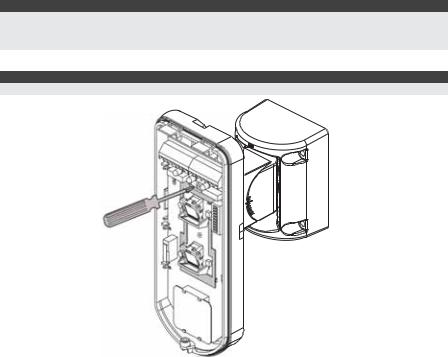
Replacing Lenses
1.Unlock the six screws that hold the lens holding sleeve from the back of the front cover.
2.To release the protective sleeve, gently push the lens from the external side of the front cover.
3.Disconnect the lens from the sleeve by gently pushing the lens clips that secure it to the sleeve.
4.Replace the lens. Place the 4 clips of the lens into the matching holes on the sleeve.
5.Insert the protective sleeve back into place on the front cover. Pay attention to place the sleeve over the sealing rubber.
6.Secure the 6 holding screws back to their place.
Lens Locking
Clips
Sleeve Locking
 Screws
Sealing Rubber
Lens Protecting
Sleeve
Front Cover
Locking Screw
Sockets for
Lens Clips
WatchIN Installation Manual |
11 |

Lens Types |
|
|
|
|
|
|
|
|
|
|
|
|
|
|
|
|
|
|
|
|
|
Wide angle lens (RL325): Top view |
|
|
|
|
|
||||||
Feet |
Meters |
|
|
|
|
|
|
|
|
|
|
|
|
|
|
|
60 |
18 |
|
|
|
|
|
|
|
|
|
|
|
|
|
|
|
|
16 |
|
|
|
|
|
|
|
|
|
|
|
|
|
|
|
50 |
|
|
|
|
|
|
|
|
|
|
|
|
|
|
|
|
|
14 |
|
|
|
|
|
|
|
|
|
|
|
|
|
|
|
40 |
12 |
|
|
|
|
|
|
|
|
|
|
|
|
|
|
|
|
10 |
|
|
|
|
|
|
|
|
|
|
|
|
|
|
|
30 |
|
|
|
|
|
|
|
|
|
|
|
|
|
|
|
|
|
8 |
|
|
|
|
|
|
|
|
|
|
|
|
|
|
|
20 |
6 |
|
|
|
|
|
|
|
|
|
|
|
|
|
|
|
|
4 |
|
|
|
|
|
|
|
|
|
|
|
|
|
|
|
10 |
|
|
|
|
|
|
|
|
|
|
|
|
|
|
|
|
|
2 |
|
|
|
|
|
|
|
|
|
|
|
|
|
|
|
0 |
0 |
|
|
|
|
|
|
|
|
|
|
|
|
|
|
90° |
|
2 |
|
|
|
|
|
|
|
|
|
|
|
|
|
|
|
10 |
|
|
|
|
|
|
|
|
|
|
|
|
|
|
|
|
|
4 |
|
|
|
|
|
|
|
|
|
|
|
|
|
|
|
20 |
6 |
|
|
|
|
|
|
|
|
|
|
|
|
|
|
|
|
8 |
|
|
|
|
|
|
|
|
|
|
|
|
|
|
|
30 |
|
|
|
|
|
|
|
|
|
|
|
|
|
|
|
|
|
10 |
|
|
|
|
|
|
|
|
|
|
|
|
|
|
|
|
12 |
|
|
|
|
|
|
|
|
|
|
|
|
|
|
|
40 |
|
|
|
|
|
|
|
|
|
|
|
|
|
|
|
|
|
14 |
|
|
|
|
|
|
|
|
|
|
|
|
|
|
|
50 |
|
|
|
|
|
|
|
|
|
|
|
|
|
|
|
|
|
16 |
|
|
|
|
|
|
|
|
|
|
|
|
|
|
|
60 |
18 |
|
|
|
|
|
|
|
|
|
|
|
|
|
|
|
|
Meters |
0 |
2 |
4 |
6 |
8 |
10 |
12 |
14 |
16 |
18 |
20 |
22 |
24 |
25 |
|
|
Feet |
|
|
|
|
|
|
|
|
|
|
|
|
|
|
|
|
|
0 |
|
10 |
20 |
30 |
|
40 |
|
50 |
60 |
|
70 |
80 |
90 |
|
Wide angle lens (RL325): Side View
Typical |
10 |
3 |
Installation |
|
|
|
|
2 |
Height: |
|
|
|
|
1 |
2.4m (7'10") |
|
|
|
0 |
0 |
Meters |
0 |
2 |
4 |
6 |
8 |
10 |
12 |
14 |
16 |
18 |
20 |
22 |
24 |
25 |
|
|
||
Feet |
|
|
|
|
|
|
|
|
|
|
|
|
|
|
|
|
|
|
|
0 |
10 |
|
20 |
30 |
|
40 |
50 |
|
60 |
|
70 |
80 |
85 |
||||
12 |
WatchIN Installation Manual |

|
|
|
|
|
|
|
|
|
|
|
|
Barrier lens (RL327B): Top view |
|
|
|
|
|
|
|
|
|
|
|
|||||||||||||
Feet |
Meters |
|
|
|
|
|
|
|
|
|
|
|
|
|
|
|
|
|
|
|
|
|
|
|
|
|
|
|
|
|
||||||
10 |
|
|
|
2 |
|
|
|
|
|
|
|
|
|
|
|
|
|
|
|
|
|
|
|
|
|
|
|
|
|
|
|
|
|
|
|
|
|
|
|
|
|
|
|
|
|
|
|
|
|
|
|
|
|
|
|
|
|
|
|
|
|
|
|
|
|
|
|
|
|
|
|
|
|
0 |
|
|
|
0 |
|
|
|
|
|
|
|
|
|
|
|
|
|
|
|
|
|
|
|
|
|
|
|
|
|
|
|
|
|
|
|
|
|
|
|
|
|
|
|
|
|
|
|
|
|
|
|
|
|
|
|
|
|
|
|
|
|
|
|
|
|
|
|
|
|
|
5° |
||
|
|
|
|
|
|
|
|
|
|
|
|
|
|
|
|
|
|
|
|
|
|
|
|
|
|
|
|
|
|
|
|
|
|
|||
10 |
|
|
|
2 |
|
|
|
|
|
|
|
|
|
|
|
|
|
|
|
|
|
|
|
|
|
|
|
|
|
|
|
|
|
|
|
|
|
|
|
|
|
|
|
|
|
|
|
|
|
|
|
|
|
|
|
|
|
|
|
|
|
|
|
|
|
|
|
|
|
|
|
||
|
|
|
|
|
|
|
|
|
|
|
|
|
|
|
|
|
|
|
|
|
|
|
|
|
|
|
|
|
|
|
|
|
|
|
||
|
|
|
|
|
|
|
|
|
|
|
|
|
|
|
|
|
|
|
|
|
|
|
|
|
|
|
|
|
|
|
|
|
|
|
|
|
|
|
|
|
|
|
|
|
|
|
|
|
|
|
|
|
|
|
|
|
|
|
|
|
|
|
|
|
|
|
|
|
|
|
|
|
|
|
|
|
|
Meters |
0 |
2 |
4 |
6 |
8 |
10 |
12 |
14 |
16 |
18 |
20 |
22 |
24 |
26 |
27 |
|
||||||||||||||||
|
|
|
|
Feet |
|
|
|
|
|
|
|
|
|
|
|
|
|
|
|
|
|
|
|
|
|
|
|
|
|
|
|
|
|
|
|
|
|
|
|
|
|
|
|
|
|
|
|
|
|
|
|
|
|
|
|
|
|
|
|
|
|
|
|
|
|
|
|
|
|
|
|
||
|
|
|
|
|
|
0 |
|
|
10 |
|
20 |
30 |
|
|
40 |
|
|
50 |
|
60 |
|
|
70 |
|
80 |
|
|
90 |
|
|||||||
Barrier lens (RL327B): Side view
|
Meters |
|
|
|
|
|
|
|
|
|
|
|
|
|
|
|
|
Typical |
10 |
3 |
|
|
|
|
|
|
|
|
|
|
|
|
|
|
|
Installation |
|
|
|
|
|
|
|
|
|
|
|
|
|
|
|
|
|
Height: |
|
|
|
|
|
|
|
|
|
|
|
|
|
|
|
|
|
2.4m (7'10") |
|
1 |
|
|
|
|
|
|
|
|
|
|
|
|
|
|
|
|
|
|
|
|
|
|
|
|
|
|
|
|
|
|
|
|
|
|
0 |
0 |
|
|
|
|
|
|
|
|
|
|
|
|
|
|
|
|
Meters |
0 |
2 |
4 |
6 |
8 |
10 |
12 |
14 |
16 |
18 |
20 |
22 |
24 |
26 |
27 |
|
|
Feet |
|
|
|
|
|
|
|
|
|
|
|
|
|
|
|
|
|
|
|
0 |
10 |
|
20 |
30 |
|
40 |
50 |
|
60 |
|
70 |
80 |
|
90 |
Note:
All detection patterns are assured and approved according to EN50131 in Normal sensitivity settings (factory default).
If you change the sensitivity setting, the actual detection pattern must be assured during installation.
WatchIN Installation Manual |
13 |

Technical Specification
Electrical
Current consumption (Relay Mode) |
45mA at 12 VDC (Stand by) |
|
|
|
60mA at 12 VDC (MAX with LED ON) |
|
|
Current consumption (BUS Mode) |
30mA at 12 VDC (Stand by), |
|
|
|
45mA at 12 VDC (MAX with LED ON) |
Voltage requirements |
9-16 VDC** |
Alarm contacts |
30 VDC, 1A |
AM contacts |
24 VDC, 0.1A |
Physical |
|
Size: |
215 x 95 x 85mm |
LxWxD |
(8.5" x 3.75" x 3.35") |
Weight |
0.632 Kg (1.4lb) |
Environmental |
|
RF immunity |
40V/m (30MHz to 2GHz) |
Operating/Storage temperature |
0°C to 49°C (32°F to 120°F) |
* PIR technology is limited in rough environmental conditions.
** Use a 5A max power supply, using safety-approved wires with a minimum gauge of 20AWG.
Ordering Information
Standard Units
Part Number |
Description |
RK325DT |
WatchIN DT 10.525GHz / 10.587GHz / 9.9GHz + Swivel |
The detector contains a standard swivel and a replacement barrier lens (P/N engraved on the Lens -RL327B)
Accessories
Part Number |
Description |
Weight |
RA300B |
Barrier Swivel Kit |
0.1 Kg (0.23 lb) |
RA300P |
Pole Adaptor Kit |
0.25 Kg (0.55 lb) |
RA300C |
Conduit Adaptor Kit |
0.6 Kg (1.27 lb) |
RA300SC |
Swivel Metal Conduit Adaptor |
1Kg (2.2 lb) |
RA300HS |
WatchIN Demo |
- - |
Camera Accessories
Part Number |
Description |
WatchOUT VC1 |
Camera Cover Adaptor 1 |
WatchOUT VC017 |
NTSC / PAL Narrow Camera For WatchIN |
WatchOUT VC053 |
NTSC / PAL Wide Camera For WatchIN |
WatchOUT VCPS |
220V / 120V PAL Camera Power supply |
UL Compliance Section
To comply with UL standards, note the following:
♦When the detector is connected to the BUS of the ProSYS panel, the detectors are to be powered from either the ProSYS panel (V7.55) or a listed compatible burglar alarm power
supply that has an output voltage range that does not exceed 9-16 VDC, has a minimum of 4 hours of standby power, and is suitable for mercantile use.
♦A dead zone of 2 ft should be considered during installation.
♦The camera option is not UL listed.
♦0.6 power factor inductive load can be used on the relays.
♦Only RK325DT version 10.525GHz is UL approved.
♦The vibration option is not incorporated on UL listed products.
♦The maximum range was tested and evaluated by UL with the trimmer set to maximum MW and ACT settings for PIR.
♦On power up the detector is not operational for the first 20 seconds.
♦The detector should be tested by the installer at least once a year.
14 |
WatchIN Installation Manual |
BUS Mode Installation
Introduction
The information in this section relates to WatchIN DT installation in BUS Mode only. Up to 32 BUS detectors can be installed on the ProSYS RS485 BUS, saving cabling time and enabling remote control and diagnostics.
Terminal Wiring
+,- |
Used for the connection of 12VDC power supply. Connect the (+) terminal to |
||
|
|
the AUX RED and the (–) terminal to the COM BLK of the ProSYS terminals |
|
|
YELLOW |
Used for data communication with the ProSYS. Connect to the terminal to the |
|
|
|
BUS YEL of the ProSYS |
|
|
|
|
|
|
GREEN |
Used for data communication with the ProSYS. Connect to the terminal to the |
|
|
|
BUS GRN of the ProSYS |
|
|
|
|
|
|
TAMPER |
Used for the wiring for tamper detection, see below |
|
|
LED |
Used for the wiring for tamper detection, see below |
|
|
ENABLE |
|
|
|
|
|
|
|
|
|
|
|
Note: |
|
|
|
|
|
|
All the terminals not mentioned in the table above are unused.
|
|
Cover and Back Tamper |
|
|
|
|
|
Cover Tamper Only |
|
|
|
|||||||
|
|
|
|
|
|
|
|
|
|
ProSYS BUS |
|
|
|
|
|
|
||
|
ProSYS BUS |
|
|
|
|
|
|
|
|
|
|
|
BUS Mode: |
|
|
|
||
|
|
|
|
|
|
|
|
|
|
|
|
|
|
|
|
|
||
|
|
|
|
|
|
|
|
|
|
|
|
|
Cover Tamper Wiring |
|
|
|||
|
|
|
|
|
|
|
|
|
AUX |
COM |
BUS |
|
|
|
|
|
|
|
|
|
|
|
|
BUS Mode: |
|
|
RED |
BLK |
YEL |
GRN |
|
Short |
|
|
|
|
|
AUX |
COM |
BUS |
|
Cover + Back tamper wiring |
|
|
|
|
|
|
|
|
|
|
|
|||
|
|
|
|
|
|
|
|
|
|
|
|
|
|
|||||
RED |
BLK |
YEL GRN |
|
|
|
|
|
|
|
|
|
|
|
|
|
|
|
|
|
|
|
Short |
|
|
|
|
|
|
|
|
|
|
|
|
|
|
|
|
|
|
|
|
|
BACK |
|
|
|
|
|
|
|
|
|
|
|
|
|
|
|
|
|
|
TAMPER (N.C) |
|
|
|
|
|
|
|
|
|
|
||
|
|
|
|
|
|
|
|
|
|
|
|
|
FREE |
FREE |
|
LED |
|
SET/ |
|
|
|
|
|
|
|
|
|
+ |
- |
N.O. COM N.C. |
(YEL) TAMPER |
(GRN) |
AM |
ENBL |
TEST |
UNSET |
|
|
|
|
FREE |
|
FREE |
|
LED |
|
SET/ |
|
|
|
|
|
|
|
|
|
+ |
- |
N.O. COM N.C. |
(YEL) |
TAMPER |
(GRN) |
AM |
ENBL |
TEST |
UNSET |
|
|
|
|
|
|
|
|
|
|
|
|
|
|
|
Cover Tamper to Zone Input |
|
|
|
|
|
|
||||||
|
|
|
|
|
ProSYS BUS |
|
|
Zone Input |
|
|
|
|
|
|
|
|
||
|
|
|
|
|
|
|
|
|
|
|
|
|
|
|
|
|
||
|
|
|
|
|
|
|
|
|
|
|
|
BUS Mode: |
|
|
|
|
|
|
|
|
|
|
|
|
|
|
|
Zone |
Cover Tamper to Zone Input |
|
|
|
|
|
|||
|
|
|
|
AUX |
COM |
BUS |
|
|
Z1 COM |
Z2 |
|
|
|
|
|
|
|
|
|
|
|
|
|
|
|
|
|
|
|
|
|
|
|
|
|||
|
|
|
|
RED |
BLK |
YEL GRN |
|
|
|
|
|
|
|
|
|
|
|
|
|
|
|
|
|
|
|
|
|
|
|
Short |
|
|
|
|
|
|
|
|
|
|
|
|
|
|
|
FREE |
FREE |
|
LED |
SET/ |
|
|
|
|
|
|
|
|
|
|
+ |
- |
N.O. COM |
N.C. |
(YEL) |
TAMPER (GRN) |
AM |
ENBL |
TEST UNSET |
|
|
|
|
|
|
WatchIN Installation Manual |
15 |

DIP Switch Settings
DIP Switch |
Description |
Number |
|
1 - 5 |
Used to set the detector ID number. Set the ID number in the same way as for |
|
any other ProSYS accessory (Refer to the table below). |
6 - 10 |
Not used |
WatchIN ID: DIP Switches 1 - 5
ID |
1 |
2 |
3 |
4 |
5 |
|
|
|
|
|
|
01 |
OFF |
OFF |
OFF |
OFF |
OFF |
|
|
|
|
|
|
02 |
ON |
OFF |
OFF |
OFF |
OFF |
03 |
OFF |
ON |
OFF |
OFF |
OFF |
04 |
ON |
ON |
OFF |
OFF |
OFF |
05 |
OFF |
OFF |
ON |
OFF |
OFF |
06 |
ON |
OFF |
ON |
OFF |
OFF |
07 |
OFF |
ON |
ON |
OFF |
OFF |
08 |
ON |
ON |
ON |
OFF |
OFF |
09 |
OFF |
OFF |
OFF |
ON |
OFF |
10 |
ON |
OFF |
OFF |
ON |
OFF |
11 |
OFF |
ON |
OFF |
ON |
OFF |
12 |
ON |
ON |
OFF |
ON |
OFF |
13 |
OFF |
OFF |
ON |
ON |
OFF |
14 |
ON |
OFF |
ON |
ON |
OFF |
15 |
OFF |
ON |
ON |
ON |
OFF |
16 |
ON |
ON |
ON |
ON |
OFF |
|
|
|
|
|
|
ID |
1 |
2 |
3 |
4 |
5 |
|
|
|
|
|
|
17 |
OFF |
OFF |
OFF |
OFF |
ON |
18 |
ON |
OFF |
OFF |
OFF |
ON |
19 |
OFF |
ON |
OFF |
OFF |
ON |
20 |
ON |
ON |
OFF |
OFF |
ON |
21 |
OFF |
OFF |
ON |
OFF |
ON |
22 |
ON |
OFF |
ON |
OFF |
ON |
23 |
OFF |
ON |
ON |
OFF |
ON |
24 |
ON |
ON |
ON |
OFF |
ON |
25 |
OFF |
OFF |
OFF |
ON |
ON |
26 |
ON |
OFF |
OFF |
ON |
ON |
27 |
OFF |
ON |
OFF |
ON |
ON |
28 |
ON |
ON |
OFF |
ON |
ON |
29 |
OFF |
OFF |
ON |
ON |
ON |
30 |
ON |
OFF |
ON |
ON |
ON |
31 |
OFF |
ON |
ON |
ON |
ON |
32 |
ON |
ON |
ON |
ON |
ON |
|
|
|
|
|
|
ProSYS Programming (from ProSYS software version 7.xx and above)
The following section describes the additional software programming options, added to the ProSYS software, that concern the settings of the WatcIN DT as a BUS detector. Up to 32 BUS detectors can be added to the system (16 in ProSYS 16) and each of them comes at the expense of a zone in the system.
It is recommended to read and fully understand the ProSYS Installation Manual (P/N: 5IN1383) and User Manual (P/N: 5IN1382), before programming the WatchIN.
Notes:
The WatchIN is compatible with the ProSYS software Version 7.xx and above.
The WatchIN can be programmed via the U/D Software supporting ProSYS software Version 7.xx and above.
For maximum operation stability, it is best NOT to exceed a total of 300 meters (1000 feet) of wiring when connecting the WatchIN to the BUS.
Adding / Deleting the WatchIN DT
The WatchIN is part of an accessory category, BUS zones. Therefore, Adding/Deleting the WatchIN is identical to any other accessory with the following exception:
Each BUS Zone Detector should be assigned to a Regular Zone.
Any BUS detector can be assigned to a physical wired zone or to a virtual zone.
Physical zone: Any zone on the ProSYS PCB (zones 1-8) or on a wired zone expander (ZE08, ZE16).
Virtual zone: Any zone on a BUS zone expander defined as BZ08 or BZ16.
16 |
WatchIN Installation Manual |
Notes:
Virtual BUS zones are cost effective. They enable to expand your system zones without adding physical zone expanders.
The virtual BUS zone expander can be used only for BUS zone detectors.
To add a BUS zone expander select type BZ08 or BZ16 when adding a zone expander (Quick key [7][1][2]).
1.To Add / Delete the WatchIN DT
1.From the installer menu enter the Add/Delete menu: Quick Key [7][1][9][5] for BUS Zones detectors.
2.Use the  /
/  or
or  /
/  keys to position the cursor over the BUS Zone ID number for which you want to assign (or delete) a detector.
Note:
Make sure that the detector's physical ID number is identical to the ID number you select during programming.
3.Place the cursor on the TYPE field and use the  /
/  key to select IDT25 for the WatchIN DT detector.
4.Press  /
/  to confirm.
5.Repeat the process for the other BUS detectors.
2.Assigning the WatchIN DT to a Zone
1.From the main installer menu enter Zones: One by One option (Quick key [2][1])
2.Select the zone number that you want to assign the BUS detector.
Note:
If you have defined a BUS Zone Expander, select a zone number from the virtual zones (defined by the BUS zone expander).
3.Define Partitions, Groups, Zone Type and Zone Sound.
4.In the Termination category select [5] BUS Zone followed by  /
/  . The following display appears:
Z:001 |
LINK TO: |
ID:01 TYPE=IDT25
5.Select the BUS zone number to assign to the programmed zone. The type field will be updated automatically when selecting the zone.
6.Press  /
/  . The loop response category is not applicable to a BUS zone and the following display appears:
Z:001 RESPONSE:
N/A-BUS ZONE
7. Press  /
/  , assign label and press
 /
/  .
.
Configuring the WatchIN DT Parameters
1.To access the WatchIN settings option press [2][0][3] from the main installer menu. The following display appears:
B- ZONE PRMS:
ZONE#=001 (0:01)
2.Select the zone that the BUS zone was assigned to and press  /
/  . You can now program the WatchIN parameters as follows:
WatchIN Installation Manual |
17 |
Zones Miscellaneous: BUS Zone
Quick Keys |
Parameter |
|
|
|
Default |
|
|
|
|
|
|
|
|
[2][0][3][zzz] |
|
LEDS |
|
|
|
3 LEDS |
[1] |
|
Defines the LEDS operation mode |
|
|||
|
|
|
|
|
|
|
[2][0][3][zzz] |
|
Off |
|
|
|
|
[1][1] |
|
Disables the LEDS operation |
|
|
|
|
|
|
|
|
|
|
|
[2][0][3][zzz] |
|
Red Only |
|
|
|
|
[1][2] |
|
Only the Red led will operate. This option is highly recommended to avoid |
||||
|
|
the possibility that the intruder will “Learn” the detector behavior. |
||||
|
|
|
|
|
|
|
[2][0][3][zzz] |
|
3 LEDS |
|
|
|
|
[1][3] |
|
All 3 LEDs will operate. |
|
|
|
|
|
|
|
|
|
|
|
[2][0][3][zzz] |
|
Detection Sensitivity |
|
|
Normal |
|
[2] |
|
Defines the sensitivity of the detector(MW + PIR) |
|
|||
|
|
|
|
|
|
|
[2][0][3][zzz] |
|
Sensitivity Options |
|
|
|
|
[2][1]..[4] |
|
1) Low |
3) Normal |
|
|
|
|
|
2) Medium |
4) ACT (Anti-Cloak™ Technology) |
|||
|
|
|
|
|
|
|
[2][0][3][zzz] |
|
MW Range |
|
|
|
Trimmer |
[3] |
|
Defines the microwave channel range (maximum range - 27m) |
||||
|
|
|
|
|
|
|
[2][0][3][zzz] |
|
MW Range options |
|
|
|
|
[3][1]..[7] |
|
1) Minimum |
3) 40% |
5) 80% |
|
7) Trimmer (MW is |
|
2) 20% |
4) 60% |
6) Maximum |
defined by the trimmer |
||
|
|
|
|
|
|
setting on the PCB) |
[2][0][3][zzz] |
|
Alarm Logic |
|
|
|
PIR and Microwave |
[4] |
|
Determine the detector’s logic of defining an alarm. |
||||
[2][0][3][zzz] |
|
PIR and Microwave |
|
|
|
|
[4][1] |
|
Alarm is activated when both PIR and MW channels detect an alarm |
||||
|
|
|||||
|
|
(AND Logic) |
|
|
|
|
|
|
|
|
|
|
|
[2][0][3][zzz] |
|
PIR or Microwave |
|
|
|
|
[4][2] |
|
An alarm is activated when either PIR or MW channels detect an alarm (OR |
||||
|
|
|||||
|
|
Logic) |
|
|
|
|
|
|
|
|
|
|
|
[2][0][3][zzz] |
|
Lens Type |
|
|
|
Wide Angle |
[5] |
|
Defines the actual Lens of the detector |
|
|||
|
|
|
|
|
|
|
[2][0][3][zzz] |
|
Lens Type Options |
|
|
|
|
[5][1]..[2] |
|
1) Wide Angle |
2) Barrier |
|
|
|
[2][0][3][zzz] |
|
Anti-Mask |
|
|
|
Enable |
[6] |
|
Defines the operation of Anti Masking detection |
|
|||
|
|
|
|
|
|
|
[2][0][3][zzz] |
|
Anti-Mask Options |
|
|
|
|
[6][1]..[2] |
|
1) Disable 2) Enable (Default) |
|
|
|
|
|
|
|
|
|
|
|
Quick Keys |
Parameter |
|
|
|
Default |
|
|
|
|
|
|
|
|
[2][0][3][zzz] |
|
Arm/Disarm |
|
|
|
No |
[7] |
|
Defines the operation of the LEDs and the anti masking detections while the |
||||
|
|
|||||
|
|
detector is armed |
|
|
|
|
|
|
|
|
|
|
|
[2][0][3][zzz] |
|
No |
|
|
|
|
[7][1] |
|
AM (Anti masking) is enabled |
|
|
|
|
|
|
LEDs behave according to the LEDs parameter definition |
||||
|
|
|
|
|
|
|
[2][0][3][zzz] |
|
Yes |
|
|
|
|
[7][2] |
|
AM (anti masking) is disabled |
|
|
|
|
|
|
LEDs are disabled |
|
|
|
|
|
|
|
|
|
|
|
[2][0][3][zzz] |
|
Green line |
|
|
|
Yes |
[8] |
|
The WatchIN includes a Green Line feature that follows environmental |
||||
|
|
|
|
|
|
|
18 |
WatchIN Installation Manual |
 Loading...