


G T 4 9 0 X
C o n t r o l P a n e l
Engineer’s
Reference Guide

|
GT490X Engineer’s Reference Guide |
|
|
CONTENTS |
|
|
IMPORTANT ........................................................... |
2 |
1 |
Introduction............................................................ |
3 |
2 |
System Installation - Wiring.................................. |
4 |
3 |
Resetting Factory Defaults ................................... |
12 |
4 |
Programming ......................................................... |
14 |
|
Moving Around ............................................... |
14 |
|
Headers & Options ........................................ |
14 |
|
Common Options with Menu Numbers .......... |
17 |
|
Programming Zones ...................................... |
18 |
|
Reporting a Mains Fail on a PSU ................... |
30 |
|
Programming Setting Modes ......................... |
31 |
|
Programming Entry Times ............................. |
38 |
|
Programming Bells / Sounders ...................... |
40 |
|
Programming Keypad .................................... |
44 |
|
Programming Digicom / Vo-Comm Off/On ..... |
48 |
|
Programming Linefault Modes ...................... |
58 |
|
Programming Panic ...................................... |
60 |
|
Programming PGM2 / PGM3 / Timers............ |
62 |
|
Programming Reset Modes ........................... |
66 |
|
Programming Sounder Levels ....................... |
68 |
|
Programming PGM 1 / Timers ....................... |
70 |
|
Programming Engineer Code ........................ |
72 |
|
Programming Service .................................... |
73 |
|
Programming Custom Screens ..................... |
75 |
|
Programming Diagnostics / Log .................... |
76 |
|
Programming Alarm Confirm (Notes) ............. |
80 |
|
Programming Alarm Confirm ......................... |
84 |
|
NovActive Description & Programming .......... |
89 |
|
Programming Point ID & SIA Protocols .......... |
91 |
|
Linefault Sounders Description ...................... |
93 |
|
Engineer Reset............................................... |
94 |
|
Wiring Proximity ‘E’ & ‘I’ Readers ................... |
95 |
|
Clearing ‘Test Fail’ Indication ......................... |
96 |
5 |
Specifications ........................................................ |
97 |
6 4 Wire Contour RKP Wiring Information.............. |
101 |
|
|
Testing the Battery Charge Voltage ............... |
102 |
7 |
PD6662:2010 UPDATE - New Features ................ |
104 |
Page 1

GT490X Engineer’s Reference Guide
|
IMPORTANT! |
|
|
|
|
Input: |
|
AC230V +/-10% ~50Hz 125mA Max. 35W Max |
Nominal Temp Range: |
|
0 - 50ºC |
Humidity |
|
70% non-condensing |
|
|
GT490X Metal |
|
|
For Indoor Use Only |
|
|
|
This equipment is intended only for use as a Security Alarm Control Panel. Adequate ventilation away from heat and humidity must be provided. The unit must be fixed securely to a non-flammable surface using suitable fixings.
All mains wiring must conform to the relevant current IEEE wiring regulations (or appropriate international regulatory standards). See Mains Supply Connection section within this manual for more detailed instructions.
All wiring must be protected from sharp or jagged edges.
All low voltage (alarm) wiring must be to the appropriate international regulatory standards and comply to good wiring practice and should be routed away from the mains cables.
Replacement fuses should be of the same type and rating conforming to IEC 127. The GT490X Control Panel is fitted with resettable fuses. The areas protected are Battery, Aux and Keypad. In the event of a fuse tripping or an input/ output not working, remove the source of the load and check wiring for shorts. Check any added devices for full functionality before any reconnection.
The maximum current draw from the unit for all output combinations must not exceed
1A.
Sounders, detectors and other auxiliary items, including the control panel and keypad(s), should be included when calculating current drawn by the system.
Any damage caused through overloading the Control Panel Supply will not be covered by the warranty.
We recommend that additional power supplies are used to supply detectors on long cable runs.
The unit is intended for use with a suitable re-chargeable lead acid battery permanently connected to the appropriate terminals.
All documentation and manuals must be thoroughly read by suitably qualified installation personnel prior to installation.
Page 2

GT490X Engineer’s Reference Guide
 Important Safety Information. Hazardous Voltages Inside.The unit has no user serviceable parts inside. No User Access. Internal access should only be by suitably qualified personnel.
The unit MUST be Earthed. It is the responsibility of the installation engineer to ensure that the earth connection to the unit lid is good on completion of the installation or after service.
1 INTRODUCTION
The GT490X Control Panel is a microprocessor based unit that has been designed to be suitable for all types of domestic and commercial installations. All zones are fully programmable by the engineer.
On power up / reset, the Control Panel can be set to the old BS or EN2 (Grade 2) operating standards. It is ESSENTIAL that a 4 6 YES NO reset is done to all new systems before commencement of programming.
Upon completion of the installation the engineer may, if required, re-program several factory set options so as to tailor the Control Panel to suit the requirements of the system.
The GT490X Control Panel uses 32 character LCD Remote Keypads for control of the system via User Code(s) and programming of the system via an Engineer Code. The Factory Default Codes are:
Default Master User Code |
5678 |
Default Engineer Code |
1234 |
The Engineer code may be ‘Locked’ into the system during engineer programming and it should be noted that if the ‘Locked’ code is not known the only way to have it returned to the factory default is to return the PCB to the factory.
Option Formats. When an option cannot be changed the display will show a : rather than the usual = sign. Pressing the No key is disregarded and the panel will react as though the Yes key has been pressed (i.e. it will move onto the next option).
Page 3
GT490X Engineer’s Reference Guide
2 SYSTEM INSTALLATION - WIRING
Planning the Control Panel Location
Consideration in locating the fixing position of the Control Panel should be given to:
Access for the routing of cables for the system from detection devices, sounders (internal and external), remote keypads, mains, etc.
The position of the underside retaining screw.
The fixing of a 3 amp fused spur with disconnection facility.
When fitting the RKP(s) consideration should be given to:
Operation of the keypad.
Readability of the display.
The Panel should be fixed to the wall using appropriate wall plugs and No.8 screws at least 30mm long. Do not tighten the screws at this stage, wait until all your wiring is in place.
Wiring Considerations
With the exception of the mains wiring all interconnections should be made with multicore 7/.02 alarm cable.
Good wiring practice should be observed throughout the installation and the following tips may prove useful.
Never run alarm cables parallel to mains cables, telephone cables or any other cables that may be carrying inductive loads
Whenever you have to cross mains cables with alarm cables ensure that you do so at 90°
Whenever possible wire the mains connection for the control panel back to the consumer unit via a 3A fused spur with disconnection facility.
Never tap into ring main circuits that have fridges/freezers on them.
Never tap into lighting circuits that have fluorescent lighting units on them.
Page 4
GT490X Engineer’s Reference Guide
 Mains Wiring - WARNING: Electricity can KILL
Before connecting the control panel ALWAYS disconnect the supply at the consumer unit. A 230V a.c supply should be taken directly from the consumer unit. In order to comply with the relevant current wiring regulations this should be via a 3 Amp fused spur with disconnection facility. This must be carried out by a suitably qualified electrician. If you are in any doubt please contact your local electricity company for advice.
This control panel MUST be Earthed.
Mains
Connection Colours
|
Live |
= Brown (Red) |
|
||
|
Neutral |
= Blue (Black) |
|
||
|
Earth |
= Copper |
Consumer Unit
Yellow/Green sleeving should be used for Copper Earth Conductor
Unswitched
Fused Spur
Control Panel Mains
Terminal Block
Page 5
GT490X Engineer’s Reference Guide
Wiring Diagrams - GT490X PCB
GTAG PROXIMITY READER(S) |
|
STROBE / |
EXTERNAL |
MODULE |
SOUNDER |
locked been has it if |
Default not will This Code Engineer the |
. |
|
|
|
|
|
|
|
|
|
|
|
Ohm 680 |
inRKPlast the line, the |
chaindaisy in beshouldthis |
ONEtofitted be If.RKPsthe of wiredare RKPs |
Ohm680Note: shouldresistor |
|
|
|
|
|
|
|
12V |
0V |
D1/A |
D2/B |
|
|
|
|
|
|
|
DAISYCHAIN FORMAT |
REMOTE KEYPAD(S) WIRED BE MAY OR STAR IN |
12V 0V D1/A D2/B |
|
|
|
|
|
|
|
|
|
|
|
|
|
|
|
|
|
|
12V |
0V |
D1 |
|
D2 |
GRN |
YEL |
BLK |
RED |
|
|
|
|
|
|
PGM2 |
REMOTEKEYPAD |
|
|
RS485 |
|
|
||||
|
|
|
|
|
|
|
CONNECTIONS |
|
|
CONNECTIONS |
|
BATT + - |
|||
|
|
|
|
|
|
|
|
|
|
|
|||||
|
Strobe - Trigger |
|
STROBE |
+ - |
KEYPAD |
|
|
RS485(RADIOEXPANDER) |
AC |
||||||
|
|
|
|
|
|
|
|
|
|
||||||
Bell / Strobe + Hold-Off |
|
|
|
|
|
|
|
|
|
||||||
|
|
Bell - Trigger |
|
BELL |
- |
|
|
|
|
|
|
|
|
|
|
|
|
|
|
|
|
|
|
|
|
|
|
|
|||
Bell Hold-Off - Supply |
|
HOLD |
BELL |
|
|
|
|
|
|
|
|
|
|||
|
- Tamper Return |
|
TMPR |
SAB |
|
|
|
|
|
|
|
|
|
||
|
|
|
|
|
|
|
|
|
|
|
|
|
|||
|
|
SPEAKERS INTERNAL OHM 16 MIN |
|
|
AUX |
+ SPR SPR+ PGM1 |
|
|
|
|
|
|
|
|
|
|
|
|
|
|
- 12V |
|
|
|
|
|
|
|
|
|
|
|
|
|
|
|
|
+ |
|
|
|
|
|
|
|
|
|
|
|
|
|
available Connections |
TZ |
|
|
|
|
|
|
|
|
|
|
|
|
|
dependant model |
- + - + - + - + - AZ4 AZ3 AZ2 AZ1 |
|
|
|
|
|
|
|
|
|
||
|
|
|
|
are |
- + AZ5 |
|
|
|
|
|
|
|
|
|
|
|
|
|
|
|
AZ6 |
+ |
|
|
|
|
|
|
|
|
|
|
|
|
|
|
|
|
|
|
|
|
|
|
|
|
|
|
|
|
|
|
|
- |
|
|
|
|
|
|
|
|
|
.No Yes 6 4 |
.No version Whilst enter displayed is |
Panel Default To .Up Power |
User Default .5678 |
Code Engineer Default .1234 |
AON - + - + AZ8 AZ7 |
|
|
|
/ Tamper Case |
|
|
|
|
|
|
|
PREMISESON |
2 OTHER SOCKETS5 |
|
PATCH LEAD CONNECTION |
|
AOUT AIN |
|
JUMPER |
|
Bypass |
|
|
|
|
|
|
3 |
TAMPER EXT MODEM |
J1 |
|
Jumper |
|
|
|
|
|
|||||
|
|
|
|
|
0V |
|
|
|
|
|
|
|
|
|
|
|
|
|
|
|
12V |
|
|
|
|
|
|
|
|
|
|
|
|
|
|
|
OUT |
|
|
|
|
|
|
|
|
|
|
|
|
|
|
|
IN |
|
|
|
|
|
|
|
|
|
|
|
|
|
|
|
|
|
|
|
|
|
TELEPHONE CONNECTIONS |
||||
|
|
|
|
|
|
|
|
|
|
|
PSTN OUT |
LINE IN |
|||
|
|
|
|
|
|
|
|
|
|
|
C3 |
B2 |
A5 |
B2 |
A5 |
|
|
|
|
|
|
|
|
|
|
|
|
|
|
IN |
LINE |
|
|
|
|
|
Page 6 |
|
|
|
|
|
|
|
|||
GT490X Engineer’s Reference Guide
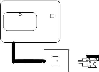
Remote Keypads
Up to four remote keypads may be fitted to the GT490X control panel. Each Keypad offers a 32 character backlit LCD.
A four core connection will be required between the control panel and remote keypad(s), keypads may be in a 'daisy chain' or ‘star’ format.
Note: 680 Ohm resistor must be fitted to ONE RKP. If the RKPs are wired in daisy chain format this should be the last RKP in the line.
Note: Each keypad must be programmed onto the system in order for it to be recognised by the system.
Note: Depending on the variant of keypad fitted external G-Tag Proximity Reader(s) may be fitted to each Remote Keypad.
Note: 680 Ohm resistor should be fitted to ONE of the RKPs. If RKPs are wired in daisy chain this should be the last RKP in the line,
BATT AC
-+
RED |
RS485 |
|
CONNECTIONS |
RS485 GRN YELBLK |
(RADIOEXP |
ANDER) |
680 Ohm
D1/A D2/B |
REMOTE D1 D2 |
0V |
KEYPAD 0V |
12V |
12V |
|
PGM2 |
KEYPAD
CONNECTIONS
-+ -
STROBE BELL
D2/B D1/A 0V 12V
REMOTE
KEYPAD(S)
MAY BE WIRED
IN STAR OR
DAISYCHAIN
FORMAT
GTAG
PROXIMITY
READER(S)
Note: Please refer to the back of this manual if the Control Panel has been supplied with a 4 Wire Contour RKP (with added zones) for wiring information.
Page 7
GT490X Engineer’s Reference Guide
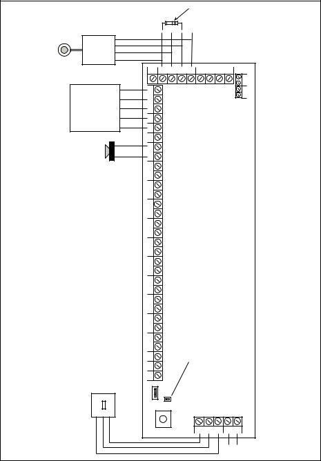
Control Panel Output Connections
S
|
|
|
|
|
|
|
|
|
|
|
- |
+ |
|
- |
BELL |
SAB |
PGM1 |
SPR+ SPR |
+ |
- |
|
STROBE BELL |
|
HOLD |
TMPR |
|
|
|
AUX 12V |
|||
|
|
|
|
|
|
|
|
|
|
|
|
|
|
|
|
|
|
|
|
|
|
|
|
|
|
|
|
|
|
|
|
|
StrobeTrigger |
Strobe+ Hold-Off |
BellTrigger |
-HoldOff - Supply |
TamperReturn |
|
|
|
|
|
|||||
|
|
|
|
|
|
||||||||||
|
INTERNAL SPEAKERS |
||||||||||||||
|
|
|
|
|
|
|
|
|
|
|
|
MIN 16 OHM |
|||
|
|
|
Bell / |
|
|
Bell |
|
|
|
|
|
|
|
||
|
|
|
EXTERNAL SOUNDER |
|
|
|
|
|
|||||||
|
|
|
/ STROBE MODULE |
|
|
|
|
|
|
|
|||||
|
|
|
|
|
|
|
|
|
|
|
|
|
|
|
|
Digi Modem
The GT490X control panel feature an onboard Digi modem. The Digi provides all the features of an eight channel communicator whilst the Modem provides facilities for Gardtec Remote Upload/Download software package.
Telephone Connections
Serial Telephone Connection
(Depending on model)
Standard
Telephone
Connection
|
|
|
|
|
|
|
|
|
|
|
A5 |
|
|
|
|
|
Terminal 5 |
|
|
|
|
|
|
|
|
|
|
|
|
|
(on other extension sockets) |
||||
|
|
|
|
|
|
|
|
|
|
|
|
|
|
|
|
||
|
|
|
|
|
|
|
|
|
|
|
|
|
|
|
|
|
Terminal 2 |
|
|
|
|
|
|
|
|
|
|
|
B2 |
(on other extension sockets) |
|||||
|
|
|
A5 |
|
B2 |
|
|
|
|
|
|
|
|
||||
|
|
|
|
|
|
|
|
|
|
|
|
|
|
||||
|
|
|
IN |
|
IN |
|
|
|
C3 |
|
|
|
|
|
Terminal 3 |
||
Terminal 5 |
|
|
|
|
|
|
|
|
|
|
|
|
(on other extension sockets) |
||||
|
|
|
|
|
|
|
|
|
|
|
|
|
|
||||
|
|
|
|
|
|
|
|
Terminal 3 |
|||||||||
(on existing BT Master socket) |
|
|
|
|
|
|
|
|
|||||||||
|
|
|
|
|
|
(on existing BT Master socket) |
|||||||||||
|
|
|
|
|
|
|
|
|
|
||||||||
|
|
|
|
|
Terminal 2 |
|
|
|
|
|
|
|
|
||||
(on existing BT Master socket) |
|
|
|||||||||||||||
|
|
|
|
|
|
|
|
|
|
|
|
|
|
|
|||
|
|
|
|
|
|
|
|
|
|
|
|
|
|
|
|||
|
|
|
|
|
|
|
|
|
|
|
A5 |
|
|
||||
|
|
|
|
|
|
|
|
|
|
|
|
|
|
|
|||
|
|
|
|
|
|
|
|
|
|
|
B2 |
|
|
||||
|
|
|
|
|
|
|
|
|
|
|
|
|
|
|
|
|
|
|
|
|
A5 |
|
B2 |
|
|
|
|
|
|
|
|
|
|||
|
|
|
|
|
|
|
|
|
|
|
|
|
|||||
|
|
|
IN |
|
IN |
|
|
C3 |
|
|
|||||||
Terminal 5 |
|
|
|
|
|
|
|
|
|
|
|
||||||
|
|
|
|
|
|
|
Terminal 2 |
|
|
||||||||
(on existing BT socket) |
|
|
|
|
|
|
(on existing BT socket) |
||||||||||
OR |
|
|
|
|
|
|
|
|
OR |
|
|
||||||
|
|
|
|
|
|
|
|
|
|
|
|||||||
Terminal A |
|
|
|
|
|
|
Terminal B |
|
|
||||||||
(on BT Terminal Block) |
|
|
|
|
|
(on BT Terminal Block) |
|||||||||||
|
|
|
|
|
|
|
|
|
|
|
|
|
|
|
|
|
|
Page 8

|
GT490X Engineer’s Reference Guide |
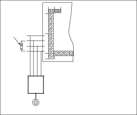
Typical Novagard 2G/2G Connections |
|
R TMP |
|
F TMP |
SAB TMP |
+12V |
BELL+ |
0V |
BELLHOLD- |
S- |
BELL- |
ST- |
STROBE- |
NovaGard 2G/4G |
GT490X Control Panel |
(Strobe terminals omitted) |
|
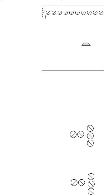
Control Panel Input (Zone Connection)
Please see following page for further wiring modes where Anti-Mask detectors are used
|
+ |
|
N/C Devices |
AZ1 |
|
|
||
|
- |
|
|
+ |
|
N/C Devices |
AZ2 |
|
|
||
|
- |
|
|
+ |
|
N/C Devices |
AZ3 |
|
|
||
|
- |
|
|
+ |
|
N/C Devices |
AZ4 |
|
|
||
|
- |
|
|
+ |
|
N/C Devices |
AZ5 |
|
|
||
|
- |
|
|
+ |
|
N/C Devices |
AZ6 |
|
|
||
|
- |
|
|
+ |
|
N/C Devices |
AZ7 |
|
multiple devices are in series |
||
|
- |
|
|
+ |
|
N/O Devices (PA etc) |
AZ8 |
|
connect across Tamper & Zone |
||
- |
||
|
||
|
+ |
|
|
TZ |
|
|
- |
|
|
|
4k7 |
+ |
|
|
6k8 |
N/C Devices |
AZ1 |
|
|
|
|
- |
|
|
|
4k7 |
+ |
|
|
6k8 |
N/C Devices |
AZ2 |
|
|
|
|
- |
|
|
|
4k7 |
+ |
|
|
6k8 |
N/C Devices |
AZ3 |
|
|
|
||
|
|
|
|
- |
|
|
|
4k7 |
+ |
|
|
6k8 |
N/C Devices |
AZ4 |
|
|
|
|
- |
|
|
|
4k7 |
+ |
|
|
6k8 |
N/C Devices |
AZ5 |
|
|
|
|
- |
|
|
|
4k7 |
+ |
|
|
6k8 |
N/C Devices |
AZ6 |
|
|
|
||
|
|
|
|
- |
|
|
|
4k7 |
+ |
|
|
6k8 |
N/C Devices |
AZ7 |
|
|
|
|
- |
|
4k7 |
|
|
+ |
6k8 |
6k8 |
6k8 |
N/C Devices |
AZ8 |
|
|
|
|
- |
|
|
4k7 |
+ |
|
|
|
6k8 |
N/C Devices |
TZ |
|
|
|
Tamper Zone |
- |
|
|
|
|
|
|
|
|
becomes Zone 9 |
|
|
|
|
ONLY when 9 (EOL) |
|
|
|
|
is selected |
|
End of Line Zone Wiring
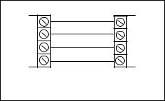
Standard (2 Wire) Zone Wiring |
Multiple units can only be used with BS Standard. |
|
If using EN2, one unit per zone. |
Page 9
GT490X Engineer’s Reference Guide
Typical Wiring Modes
Where Anti-Mask detectors are used, one of the following wiring |
12K |
|||||||||||||||||
modes may be used. |
|
|
|
|
|
|
|
|||||||||||
|
|
|
|
|
Fault/ |
|||||||||||||
|
|
|
|
|
|
|
|
|
|
|
|
|
|
|
|
|
||
|
Alarm |
|
Tamper |
|
Fault/Mask |
|
|
|
Alarm |
Tamper Mask |
||||||||
|
|
|
|
|||||||||||||||
|
|
|
|
|
|
|
|
|
|
|
|
|
||||||
|
|
|
|
|
|
|
|
|
|
|
|
|
|
|
|
|
|
|
|
|
|
|
|
|
|
|
|
|
|
|
|
|
|
|
|
|
|
6K8 4K7 12K
|
|
|
|
|
|
|
|
ELF1 wiring is used for detectors that have a |
|
|
|
|
relay output (a pair of terminals) for Fault or |
|
|
|
|
Mask. |
|
|
|
|
The installer should check what output type |
|
AZx |
||||
|
|
|
the detectors are, noting that all the dectectors |
|
|
|
|
should be of the same type with regards to the |
|
|
|
|
Fault / Mask output. |
|
6K8 |
4K7 |
ELF2 wiring is used for detectors that have a transistor output (a single terminal)
for Fault or Mask.
+ AZx - Note: For ELF2 wiring format the 12K resistor must be linked to the positive side of the zone terminals.
Typical ELF1 |
Typical ELF2 |
More Zone Wiring Methods
Zone Wiring (2 Wire) |
Zone Wiring (EOL) |
Zone Doubling (8+8) |
|
||
TZ (Tamper) |
AZ (Alarm) |
AZ (Alarm) |
AZ (Alarm) |
|
|
|
|
|
|
+ AZx - |
|
|
|
4K7 |
6K8 |
16K |
27K 6K8 |
|
|
|
|
||
N/C Tamper |
N/C Alarm |
N/C Tamper |
N/C Alarm |
|
|
Contact |
Contact |
Contact |
Contact |
|
|
|
|
|
|
Alarm N/C Tamper N/C |
Alarm N/C Tamper N/C |
|
|
|
|
1st Detector |
2nd Detector |
Zone Doubling: Detector on Zone 1 will be Zone 1 and the Doubled Zone will be Zone 9, Zone 2 will be Zone 2 and the Doubled Zone will be Zone 10. E.g Zone number + 8 = Zone number for Doubled Zone. The Zone triggered will be identified through the resistor value by the system.
Page 10
GT490X Engineer’s Reference Guide
Radio Zone Expander
One GardTec Radio Zone Expander may be fitted directly to the RS485 Bus connections on the control panel PCB without the need for any interface card. A Radio Expander card will allow eight wireless zones & eight wireless Fobs.
Radio Zone Programming
When programming Radio Zones the zone numbering for the Radio Zones will start at 91. When programming Radio Fobs the numbering of the Fobs will start at 81.
RADIO EXPANDER WIRING & SWITCH SETTINGS
(RADIO RS485CONNECTIONS ANDER)EXP
RS485
GRN YEL BLK RED
R A D I O R E C E I V E R
GRN YEL BLK RED
KEY |
ON |
|
ON |
ZONE |
RECEIVER |
ID |
|
|
|
ID |
DIP SWITCH |
|
1 2 3 4 |
|
1 2 3 4 |
|
SETTINGS |
|
|
|
|
|
Resistor Colour Codes
6K8 |
12K |
16K |
27K |
4K7 |
|||||||
|
Blue |
|
|
|
Brown |
|
Brown |
|
Red |
|
Yellow |
|
Grey |
|
|
|
Red |
|
Blue |
|
Violet |
|
Violet |
|
|
||||||||||
|
Red |
|
|
|
Orange |
|
Orange |
|
Orange |
|
Red |
|
Brown |
|
|
|
Brown |
|
Brown |
|
Brown |
|
Brown |
|
|
|
|
|
|
|
|
|
|
|
|
|
|
|
|
|
|
|
|
|
|
|
|
Page 11

GT490X Engineer’s Reference Guide
3 RESETTING FACTORY DEFAULTS
Several reset to factory default routines are available to the engineer at system powerup but it should be noted that none of these routines will ‘Un-Lock’ a ‘ Locked’
Engineer Code.
The following default routines are available.
a)Pressing 1, 9, YES, NO during initial power up will revert the Master Code and Engineer Code (not locked engineer code) back to factory defaults.
b)Pressing 3, 7, YES, NO during initial power up will revert all system settings back to defaults with the exception of the User Names and Zone Descriptors.
c)Pressing 4, 6, YES, NO during initial power up will revert all system settings back to factory defaults. It is ESSENTIAL that a 4 6 YES NO reset is done to all new systems before commencement of programming.
d)Pressing 5, 5, YES, NO during initial power up will revert all system settings to factory defaults and will also set the comms options up for GardTec Remote. ie Modem On; No Return. For commissioning systems for use with
GardTec Remote use this option.
Reset of the factory defaults and entering Engineer Mode:-
Note: It is ESSENTIAL that a 4 6 YES NO reset is done to all new systems before commencement of programming.
1)Remove all power from the system for at least ten seconds
2)Apply mains power to the control panel.
The display will show, for example:- |
GT490X |
xx-xx |
(Display will differ dependant on panel version) |
|
|
|
|
3)Whilst this display is showing (the first five seconds) press the keys shown in a, b, c or d for the reset required. (E.g. 4 6 Yes No).
The display will show:-
This may show for several minutes.
Please Wait
Page 12

GT490X Engineer’s Reference Guide
4)The display will then show:-
Select Standard 1:BS 2:EN2
Selecting 1:BS - Panel may be programmed to comply with the old BS4737 Standards. DD243 requirements will still apply.
Selecting 2:EN2 - Panel may be programmed to comply with EN50131-1 for Grade 2 Systems. BS8243 requirements will still apply.
5)Select 2:EN2.The display will then show:- This may show for several minutes.
The display will then show:-
Please Wait
Select 1:PD2004 2:PD2010
6)Select either 1 or 2 depending on which standard you require.
Note: This document assumes that 2:EN2 and PD2010 have been selected .
The display will then show:-
7)Enter Engineer code.
(1234 default). The display will show:-
8)Enter the Authorisor code. The Authorisor code is the Master User, (default 5678).
The display will show:-
|
|
|
|
|
01 Jan |
00:01:50 |
|
|
|
|
|
|
|
|
|
Enter Authorisor
Code . . . . . .
Do you want to . .
Use ENGNR. Mode ?
Note: It may be required that an engineer has to be authorised by a user before access to the engineer mode is granted.
9)Press Yes. The display will show:-
Program Zones . . . . - - -
Zones ?
From this point the panel is in Engineer Mode and all Tampers will be disabled.
Page 13

GT490X Engineer’s Reference Guide
4 PROGRAMMING
Moving Around
Enter Engineer mode as described on page 13.
The display will show:-
Program . . . . |
_ _ _ |
Zones ? |
|
|
|
Whenever three underscores are shown on the display the screen is a header.
Pressing the NO key will move to the next header.
Pressing the YES key whilst viewing a header will enter into the options under that header.
Pressing 0 will escape back one step (except when a numeric entry is required).
You are able to jump to various common options when programming by entering the relevant menu numbers. With a Header showing, key in the appropriate menu number, then press Yes. (See Page 17 for Common Options with Menu Numbers).
Below is given a complete list of headers (Shown in Bold Underline) and options that appear under each header.
Headers & Options |
Headers & Options |
Program Zones |
Entry Times |
Zone Types |
Entry Time 1 |
Zone Descriptors |
Entry Time 2 |
Zone Wiring |
|
Zone Attributes |
Bells / Sounders |
(Test/Part/Sec/Per/Chime) |
|
Zone Double Knock/Arm/Log |
Bell Type |
Zone E/E Mode |
Bell Delay/No Arms |
Event Tags |
Bell & Sounder Ring |
|
Bell Tamper Mode |
Setting Modes |
Bell For Part Set |
Setting For Full Sets |
|
Setting For Part 1 Sets |
|
Setting For Part 2 Sets |
|
Setting For Part 3 Sets |
|
Setting Delay |
|
Setting Sounders |
|
Setting Conformation |
|
Auto Part Set |
|
Page 14
Headers & Options
Keypad / Keyswitch
Keypad Alert 1 Keys
Keypad Alert 2 Keys
Function Keys
Number of Keypads
Keypad Backlight Mode
Ace / Prox
Digicom
Type or Test
Vo-Comm
Start Delay
Channels
Digicom/Modem Functions
Line Fault Modes
Line Fault Sounders
Line Fault Mode in Exit
Line Fault Log Mode
Line Fault Detect Time
Panic / Duress
PA Mode / Bells Only / Bells Always Silent Always / Bells if Line Fault Testable / Non-Testable
PA Confirm
Off/8Hr/10Hr/12Hr/14Hr/16Hr/18Hr/20Hr. Duress Off (To conform with EN standards,
Duress is defaulted to Off and cannot be changed)
PGM2 / PGM3 / Timers
PGM2/3 Operating Mode
PGM 2 Mode
PGM3 Mode
Timer 1 On Time
Timer 1 Off Time
GT490X Engineer’s Reference Guide
Headers & Options
Reset / Mains
Mains Fail Delay
Alarm Reset
Tamper Reset
Fault Reset
Alarm Restore On/Off
Abort Time
Sounder Levels
Chime Level
Entry/Exit Level
Key Beep Level
PGM1/Custom
PGM1 O/P
Custom Output 1
Custom Output 2
Custom Output 3
Custom Output 4
Custom Output 5
Custom Output 6
Custom Output 7
Custom Output 8
Engineer Code
Engineer Code
Engineer Code Locked/Unlocked
Page 15
GT490X Engineer’s Reference Guide
Headers & Options
Service
Mains OK 50Hz
Save Panel NVM to PTM Load Panel NVM to PTM Service Timer
Time To Next Service Service Tel No. Lock-Out On/Off
Engineer Mode Constant/Timed
Custom Screens
LCD Status Display
(To conform with EN standards, LCD Status is defaulted to Off and cannot be changed)
LED Status Display
Diagnostics / Log
List Event Log
Change List Diagnostics
PSU Diagnostics
NovActive Diagnostics
PSU Test Time
Change / List Test Limits
Aux Volts
Battery Volts On Charge
Battery Volts Off Charge
Headers & Options
Alarm Confirm
Window Time
On Entry
Sounder Mode
Reset Mode
Secondary Time
ET Mode
Bell Mode
Strobe Mode
Start Delay
Comms Restore
Keypad Opening
ACE Battery Monitor
In conclusion, the Yes and No Keys are used to navigate. The No Key is also used to change a value (may also require a numeric input) and the Zero Key is used to move back a level (not when display is expecting a numeric input)
If you are confident in programming the GT490X Control Panel please use the headers and options above to continue
Otherwise
Please continue with the next section for a Step by Step Guide to programming the GT490X Control Panel.
Only the major options will be covered in the Step by Step sections. After completing the sections you should be confident to program the remaining options.
Page 16
GT490X Engineer’s Reference Guide
Common Options with Menu Numbers
You are able to jump to various common options when programming by entering the relevant menu numbers. With a Header showing, key in the appropriate menu number, then press Yes.
Menu |
Jumps to |
Menu |
Jumps to |
|
1 |
PGM 1 Output |
69 |
Auto Part Set |
|
70 |
Part Set Bells |
|||
2 |
Timer 1 On Time |
|||
71 |
Zone Types ( Enter Zones) |
|||
4 |
Timer 1 Off Time |
|||
72 |
On Board Pairing |
|||
6 |
PA Mode |
|||
75 |
Program Zone Wiring |
|||
8 |
Chime Level |
|||
92 |
LCD Status |
|||
9 |
Entry Exit Level |
|||
97 |
List Event Log |
|||
10 |
Exit Sounder Mode |
|||
131 |
NovActive |
|||
11 |
Final Set Delay |
|||
139 |
PSU Test Time |
|||
12 |
Full Set Setting Time / Setting Mode |
|||
153 |
Test Zones |
|||
13 |
Part 1 Set Setting Time / Setting Mode |
|||
155 |
Confirm Time Window (BS8243 Section) |
|||
14 |
Part 2 Set Setting Time / Setting Mode |
|||
156 |
Secondary Time Window |
|||
15 |
Part 3 Set Setting Time / Setting Mode |
|||
157 |
Confirm on Entry On Off |
|||
20 |
Alert 1 Keys Mode / On Off |
|||
158 |
Sounder Trigger |
|||
21 |
Alert 2 Keys Mode / On Off |
|||
159 |
Unconfirm Reset Mode |
|||
22 |
Install Keypads |
|||
160 |
E/T Mode |
|||
23 |
Bell Delay / No. of Bell Arms |
|||
161 |
Bell Trigger |
|||
24 |
Bell Ring Time / Sounder Mode |
|||
162 |
Confirm Start Delay |
|||
26 |
NovActive On Off |
|||
164 |
Strobe Timer |
|||
27 |
Bell Tamper Ring On Off |
|||
165 |
Strobe Trigger |
|||
28 |
Entry Time 1 |
|||
166 |
Custom 1 OP Mode |
|||
29 |
Entry Time 2 / Warning Bell |
|||
167 |
Custom 2 OP Mode |
|||
30 |
Fire Zone Delay |
|||
168 |
Custom 3 OP Mode |
|||
34 |
Digicom Type |
|||
169 |
Custom 4 OP Mode |
|||
35 |
Key Beep Level |
|||
170 |
Custom 5 OP Mode |
|||
37 |
Zone Re-Arm / Double Knock Time |
|||
171 |
Custom 6 OP Mode |
|||
38 |
Engineer Code |
|||
172 |
Custom 7 OP Mode |
|||
40 |
Line Fault Sounders |
|||
173 |
Custom 8 OP Mode |
|||
41 |
Line Fault Mode |
|||
174 |
Comms Restore On Off |
|||
42 |
Line Fault Log |
|||
|
|
|||
44 |
PGM 1 Output |
|
|
46Main Fail Delay
47Tamper / Fault Reset Mode
48Backlight Mode
50Zone Response
51Zone Types
52Test Zone (Attributes)
53Save Panel NVM to PTM / Service Timer
54Service Due Weeks
55Zone Log Limit
58 Digicom Channels
64Alarm Restore / Abort Time
65Test Digicom Channels
66E/E Zones in Part Set
67Engineer Code Locked / Unlocked
68Strobe Confirm
Page 17

GT490X Engineer’s Reference Guide
Programming Zones
1)With the display showing:-
2)Enter the Engineer code (1234 default) The display will show:-
3)Enter the Authorisor code. The Authorisor code is the Master User, (default 5678).
The display will show:-
4)Press YES. The display will show:- This is Engineer Mode.
5)Press Yes. The display will show:-
6)Press Yes. The display will show:-
7)Enter the zone number you wish to program e.g 1 followed by Yes. The display will show, for example:-
8)Press No. The display will show:-
9)Note the chevron has now appeared before the Zone Type. Now press the No key until the Zone Type you require is displayed.
|
|
|
|
|
01 Jan |
00: 00: 01 |
|
|
|
|
|
|
|
|
|
Enter Authorisor
Code . . . . . .
Do you want to . .
Use ENGNR. Mode ?
|
|
|
|
|
Program . . . . |
_ _ _ |
|
|
Zones ? |
|
|
|
|
|
|
|
|
|
|
Program Zone
Types ?
Enter Zone # _ _ _
001 = Ent/Ex
= Remove -
001 > Ent/Ex
= Remove -
Page 18
GT490X Engineer’s Reference Guide
Zone Types available are:-
12 Hour
Full Alarm if Control Panel is Set.
Access
Will allow to pass through on exit.
Will allow to pass through on entry only if E/E is opened first.
24 Hour
Internal Sounder if Unset. Full alarm if Set.
Remains active in Engineer Programming Mode.
Entry/Exit (or E/E)
Zone used as last exit point (will terminate exit time if setting mode is set to E/E or Time+E/E).
Will start E/E time if opened when Control Panel is Set
Part E/E
As Access if Control Panel is Full Set
As Entry/Exit if Control Panel is Part Set
Panic
24Hour Personal Attack (or Panic Attack). Active if Control Panel is Set, Unset or in Engineer Programming Mode . May only be tested via Engineer code if programmed as testable.
Alert
Internal Sounder Only, Recorded to Log when Unset
Recorded to Log when SET
Fire
Will give Fire alarm when activated (pulsed sounders) with Control Panel Set or Unset.
Remains active in Engineer Programming Mode.
ET
Exit terminator. Used for final setting of the system. Exit Mode must be programmed for ET.
Monitor
Will write to the log once only in any one set or unset unless chime is allocated then all activations are written to the log.
KSW Bat
When used, zone should be connected to the trouble/status output of third party radio equipment that is capable of giving a low battery signal.
Line Fault
When used, acts as a Line Fault input to the control panel.
Fault
When used, will act as an Fault input to the control panel when an internal fault has been detected within the PIR.
Mask
When used, will act as an input to the control panel if the detector has been blocked or covered.
Note: Fault and Mask are treated as 24Hr but trigger a Fault Sound in Day (Unset) Mode. The Fault sound is a three tone sounder.
Page 19
GT490X Engineer’s Reference Guide
10)When you are satisfied with your selection press Yes. The display will show for example:-
001 = Ent/Ex
> Remove -
We will now be changing the Zone Attributes. Options available are:
Remove- |
The zone may not be Removed (Omitted) by the end user. (Part |
|
Sets are still allowed). |
Remove+/DK |
Zone may be Removed (Omitted) by the end user and is a Double |
|
Knock Zone (2 activations required within time window or zone left |
|
open for 15 seconds). |
Remove-/DK |
Zone may not be Removed by end user (Part Sets are still allowed) |
|
and is Double Knock Zone. |
Off |
Zone is turned Off (Use with caution). |
Norm Key |
Zone is a Keyswitch Zone for a normal type Keyswitch |
Bias Key |
Zone is a Keyswitch Zone for a Bias (momentary) type Keyswitch |
Remove+ |
Zone may be Removed by end user. |
11)Press No until the setting you require is displayed then press Yes.
12)The display will show the next zone to program. You should repeat from Step 7 until you have programmed all the zones.
13)When all required Zones have been programmed press 0 (zero) key twice. The display will show:-
Program Zone
Types ?
14)Press No. The display will show:-
Program Zone
Descriptors ?
15)Press Yes. The display will show:-
Enter Zone # _ _ _
Page 20

GT490X Engineer’s Reference Guide
16)Enter the Zone number you wish to program the Descriptor for followed by Yes. The display will show for example:-
Zone 001 Name =
Zone 001
17)Press No. The display will show:-
Zone 001 Name =
_
18)You should now program the Descriptor you require using the template below for the
key allocation in a similar way that you you would type a text message on a mobile telephone.
As the desired character is displayed press the Yes key to move on to the next character.
Continue until the line is complete.
1 |
2 |
3 |
ABC |
DEF |
GHI |
4 |
5 |
6 |
JKL |
MNO |
PQR |
7 |
8 |
9 |
STU |
VWX |
YZ Space |
No |
0 |
Yes |
Delete |
1234567890 |
Enter Character |
19)As you enter the last character the display will move on to the next Zone. For example:-
20)Repeat from Step 16 until all the Descriptors you require have been programmed. Then press 0 (zero) key twice.
The display will show:-
Zone 001 Name =
Zone 001
Program Zone
Descriptors ?
Page 21

GT490X Engineer’s Reference Guide
21)Press No. The display will show:-
22)Press Yes. The display will show:-
Note: Zone Response time is defaulted to 400ms and may not be changed.
23)Press Yes. The display will show:-
Note: Zone response time may be programmed as a global parameter. The default time is 400ms and may be reprogrammed from 2 to 14 seconds. (increments of 2 seconds).
Program Zone
Wiring ?
Zone Response :400 mS
Fault / Mask Zones
Response=Norm
The time programmed for this option will apply to all zones, there is no option for individual response times per zone. It is a global setting.
Once the Fault / Mask as been triggered the response time for the Fault / Mask will revert to the default time of 400ms until the fault / mask problem has cleared.
24)Press No until the required settings you require are displayed then press Yes. The display will show:-
On-Board Zones =9<EOL>
Wiring Modes available are.
8 |
(2 Wire) |
Two wires are used for the zone and a global tamper is used. |
9 |
(EOL) |
Two wires are used in conjunction with two resistors to give |
|
|
End Of Line wiring, this is the most secure wiring format. |
8+8 (EOL) |
This wiring method uses double EOL format to give 16 Zones |
|
|
|
from the control panel. |
Note: For information on how to wire for the various wiring modes please refer to the wiring section within this manual.
If selecting 9 (EOL) follow steps 24 through to 26. If selecting 8+8 (EOL) jump to step 28.
25)With the display showing:- Press Yes.
26)The display will show:-
On-Board Zones =9<EOL>
On-Board EOL =Norm
Page 22

GT490X Engineer’s Reference Guide Three wiring options are available under 9 (EOL):
Norm: Standard GardTec wiring configuration without Mask or Fault detection.
Note: Does not give any Fault or Masking detection and should only be used with Zone pairing.
ELF1: ELF1 wiring is used for detectors that have a relay output (a pair of terminals) for Fault or Mask..
ELF2: ELF2 wiring is used for detectors that have a transistor output (a single terminal) for Fault or Mask.
Note: We would recommend that either ELF1 Format or ELF2 Format (dependant on detector output type, Relay or Transistor) is used. ELF1 or ELF2 wiring modes will allow for Alarm, Tamper, Fault and Masking to be monitored from a single zone without the need for zone pairing.
Note: The installer should check what output type the detector are, noting that all the detectors should be of the same type with regards to the Fault / Mask output.
27) |
Press No until the setting you require is displayed |
|
|
|
|
|
|
Radio ZEX |
|
||||
|
then press Yes. The display will show. |
|
|
|||
|
|
=Off |
|
|||
|
|
|
|
|
|
|
|
|
|
|
|
|
|
|
|
|
|
|
|
|
If 8+8 EOL wiring option is required. |
|
|
|
|
||
|
|
|
|
|
|
|
28) |
With the display showing:- |
|
On-Board Zones |
|
||
|
=9<EOL> |
|
||||
|
Press No until 8+8<EOL> is displayed. |
|
|
|
|
|
|
|
|
|
|
||
|
|
|
|
|
||
|
|
|
|
|
||
|
The display will show:- |
|
On-Board Zones |
|
||
|
|
>8+8<EOL> |
|
|||
|
|
|
|
|
||
|
|
|
|
|
||
|
|
|
|
|
|
|
|
|
|
|
|||
29) |
Press Yes. The display will show:- |
|
|
|||
|
On-Board Pairing |
|
||||
|
|
|
|
=Off |
|
|
|
|
|
|
|
|
|
Zone Pairing.
A zone is used to monitor Masking and Fault.
This is achieved by selecting Zone Pairing as on. Zone Pairing cannot be used in ELF1 or ELF2 wiring modes.
When using Zone Pairing each zone will have a corresponding paired zone that will be used for Masking and Fault signals. This is done by using the Odd numbered zones for the normal alarm detection and the Even numbered zones for Masking and Fault Detection. For example.
Alarm Zone |
|
Zone 1 |
Pared Zone for Mask / Fault |
Zone 3 |
Zone 2 |
Zone 5 |
Zone 4 |
Zone 7 |
Zone 6 |
etc... |
Zone 8 |
Please note that half the zones on the system would be lost for processing the Mask and Fault signals and it would be more prudent to use the ELF1 or ELF2 modes as described previously.
Page 23

GT490X Engineer’s Reference Guide
30)Press No until the setting you require is displayed.
Then press YES. The display will show:-
31)With the display showing:-
Radio ZEX
= Off
Radio ZEX =Off
32)If you are not using Radio Detectors press Yes and jump to Step 33
Otherwise
Press No until the display shows:-
Radio ZEX
= On
Page 24

GT490X Engineer’s Reference Guide
Comprehensive instructions on how to setup and program the Radio Expansion are given in the document Hybrid Wireless Set-Up & Programming Guide supplied with the Radio Receiver.
33)Press Yes. The display will show:-
Program Radio
Functions ?
34)Press No. The display will show:-
35)Press No. The display will show:-
36)Press Yes. The display will show:-
Program Zone
Wiring ?
Program Zone
Attributes ?
Test None
Any 12Hr type zone(s) may be placed on Test. A Zone on Test will never trigger an alarm or send a central station signal. If the Zone(s) fails the Test when the system is Set the display will show Test Fail when the user Un-Sets the system. After 20 successful Sets and Un-Sets the Zone(s) will be taken out of Test by the system.
Zones on soak test.
Zones that are put on test must be indicated to the user. When setting the system the user must acknowledge this by pressing No.
37)If you do not wish to put a Zone(s) on Test press Yes and jump to Step 43
Otherwise
38)Press No. The display will show:-
39)Enter the Zone number you wish to place on Test followed by Yes.
The display will show for example:-
40)To add more Zone(s) to the Test repeat from Step 38.
Enter Zone # _ _ _
then +YES or -NO
Test 003
Page 25

GT490X Engineer’s Reference Guide
41)When you have finished adding Zones to Test press Yes.
Pt-1 None
42)The display will show:-
Three Part Sets are available on the GT490X control panel. Zones added to the PT-1 (Part 1) screen will be Removed (Omitted) when the system is Part 1 Set. Zones added to the PT-2 (Part 2) screen will be Removed (Omitted) when Part Set 2 is used. When Part Set 3 is used Parts 1 & 2 are combined and Removed (Omitted).
43)If you do not wish to enter PT-1 Zone press Yes and jump to Step 47
Otherwise
Press No. The display will show:-
44)Enter the Zone number you require for PT-1 followed by Yes.
The display will show for example:-
Enter Zone # _ _ _
then +YES or -NO
Pt-1 004
45)To add more Zones to PT-1 repeat from Step 43
46)When you have finished adding Zones to PT-1 press Yes
|
|
|
|
|
47) |
The display will show:- |
|
Pt-2 None |
|
|
|
|
||
|
|
|
|
|
|
|
|
|
|
Page 26

GT490X Engineer’s Reference Guide
48)If you do not wish to enter PT-2 Zone press Yes and jump to Step 52
Otherwise
Press No. The display will show:-
49)Enter the Zone number you require for PT-2 followed by Yes.
The display will show for example:-
Enter Zone # _ _ _
then +YES or -NO
Pt-2 005
50)To add more Zones to PT-2 repeat from Step 47
51)When you have finished adding Zones to PT-2 press Yes
|
|
|
|
|
52) |
The display will show:- |
|
Ch1 None |
|
|
|
|
|
|
|
|
|
|
|
Two Chime suites are available on the GT490X control panel so for example you would have the Front Door on Zone 1 programmed into Ch1 and the Rear Door on say Zone 6 programmed into Ch2. When the system is Unset opening the Front Door will produce a Chime. Opening the Rear Door will produce a different Chime.
It should be noted that Chime must be programmed as On from the user mode. Please refer to the User Manual for details.
Page 27

GT490X Engineer’s Reference Guide
53)If you do not wish to enter Ch1 Zone press Yes and jump to Step 57
Otherwise
Press No. The display will show:-
54)Enter the Zone number you require for Ch1 followed by Yes.
The display will show for example:-
55)To add more Zones to Ch1 repeat from Step 53
56)When you have finished adding Zones to Ch1 press Yes
57)The display will show:-
58)If you do not wish to enter Ch2 Zone press Yes and jump to Step 62
Otherwise
Press No. The display will show:-
59)Enter the Zone number you require for Ch2 followed by Yes.
The display will show for example:-
Enter Zone # _ _ _
then +YES or -NO
Ch1 001
Ch2 None
Enter Zone # _ _ _
then +YES or -NO
Ch2 006
Page 28
GT490X Engineer’s Reference Guide
60)To add more Zones to Ch2 repeat from Step 58
61)When you have finished adding Zones to Ch2 press Yes
62) |
The display will show:- |
|
|
|
|
Sec. None |
|
||
|
(See notes on Sec & Per after step 65). |
|
|
|
|
|
|
|
|
|
|
|
|
|
|
|
|
|
|
63)This concludes the Step by Step instruction for the Zone Programming.
You may continue within this section to program
Secondary Zones Perimeter Zones
Double Knock Time Window Zone Re-Arm
Zone Log Limit Zone E/E Mode Event Tags
64)Press 0 (zero) twice to return to:-
65)At this point you may press No to move to the next Header.
Or
Press 0 (zero) until the display shows:-
|
|
|
|
|
Program . . . . |
_ _ _ |
|
|
Zones ? |
|
|
|
|
|
|
|
|
|
|
|
|
|
|
|
|
|
|
|
01 Jan |
00: 00: 01 |
|
|
|
|
|
|
|
|
|
Secondary Zones:
Zones programmed as secondary will not active any sounders or comms until a normal zone activates.
This will then trigger a confirmed signal and activate the sounders as programmed.
Perimeter Zone:
Zones programmed as perimeter will activate the alarm as normal but will also activate a comms channel programmed as perimeter.
DKnock/Arm/Log:
Zones on double knock are required to activate within the double knock time window or stay active for fifteen seconds to generate an alarm condition.
|
Arm is used to program the zones to automatically re-arm after an activation. |
|
It should be noted that a zone still violated when the system times out after |
|
an alarm, will not re-armed. |
Note: |
Zone Log Limit is defaulted to On and may not be changed. Only five activations from any |
|
one zone will be recorded in the log during any set period. |
Note: |
E/E in part set entry exit zones will start the entry timer if opened in part set. |
|
12Hr in part set entry exit zones will be instant when opened in part set. |
Page 29
 Loading...