


VUpoint Cube Indoor
IP Camera
Model: RVCM11H
Installation Guide

Safety Precautions
These instructions are intended to ensure that the user can use the product correctly to avoid danger or property loss.
WARNINGS:
Installation or usage of this product that is not in accordance with the intended use as defined by the supplier and as described in the instructional materials can result in damage, injury, or death.
Make sure this product is not accessible by children and those for whom operation of the system is not intended.
All installation and operation should conform to your local electrical safety codes. The power shall conform to the requirement in the SELV (Safety Extra Low Voltage) and the Limited power source is rated 12V DC in the IEC60950-1.
If the device is permanently connected to an electrical power supply, then the connection should include an easily-accessible disconnection device, such as a circuit breaker. Do not connect the two power supplying sources to the device at the same time; it may result in device damage!
Do not ever attempt to repair your device by yourself, as doing so could result in damage, injury or death – always contact your installer / supplier agent for service.
CAUTIONS:
Make sure the power supply voltage is correct before using the camera.
Do not drop the camera or subject it to physical shock.
Do not touch sensor modules with fingers. If cleaning is necessary, use a clean cloth with a bit of ethanol and wipe it gently.
Do not aim the camera lens at the strong light such as sun or incandescent lamp. The strong light can cause fatal damage to the camera.
The sensor may be burned out by a laser beam, so when any laser equipment is being used, make sure that the surface of the sensor not be exposed to the laser beam.
Do not place the camera in extremely hot, cold temperatures (the operating temperature should be between -10°C ~ +50°C).
To avoid heat accumulation, good ventilation is required for a proper operating environment.
Keep the camera away from water and any liquid.
While shipping, the camera should be packed in its original packing.
NOTE: We assume no liability or responsibility for all the fires or electrical shock caused by improper handling or installation. We are not liable for any problems caused by unauthorized modification or attempted repair.

Introduction
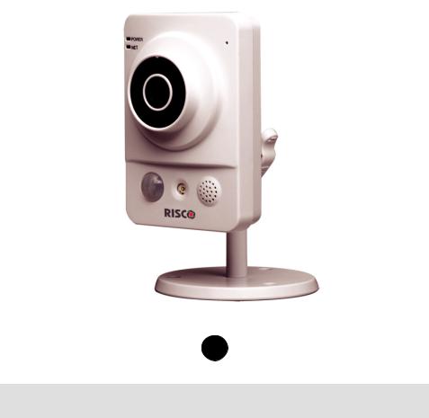
RISCO Group presents VUpoint, a revolutionary live video verification solution which seamlessly integrates IP Cameras within RISCO’s professional security systems. Powered by the RISCO Cloud (RISCO Application Server), VUpoint provides an unprecedented level of security and live video monitoring capabilities to monitoring stations and end-users alike. The RISCO cube indoor IP Camera is an important part of this solution and is easily controlled through RISCO’s intuitive Web and Smartphone applications.
Features
•Plug & Play installation
•1.3” Megapixel
•Color HD
•SD card slot for local storage
•WiFi
•IR LED (7-10m)
Components and Accessories
RISCO IP camera and mounting bracket:
Electrical power adapter and installation accessories bag:
Installation guide:
3
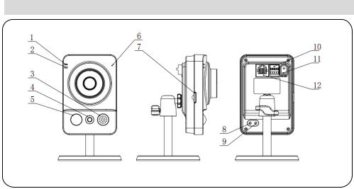
IP Camera Components and Dimensions
Figure 1 IP Camera Components
Label |
Port Name |
Indicator |
Connector |
Description |
1 |
Power |
POWER |
/ |
When camera boots up – Green |
|
indicator |
|
|
light turns on. |
|
light |
|
|
When camera is upgrading – Green |
|
|
|
|
|
|
|
|
|
light flashes. |
|
|
|
|
Interval is 0.5s. |
|
|
|
|
When camera is in alarm – Green |
|
|
|
|
light flashes. |
|
|
|
|
Interval is 0.2s. |
|
|
|
|
|
2 |
Network |
NET |
/ |
Wired network connection - Red |
|
indicator |
|
|
light is on. |
|
light |
|
|
Wireless network connection - |
|
|
|
|
|
|
|
|
|
Green light is on. |
|
|
|
|
|
3 |
Speaker |
/ |
/ |
Output audio signal (This function is |
|
|
|
|
optional). |
4 |
IR LED |
Red LED |
/ |
During darkness, the IR LED turns on |
|
|
|
|
automatically. |
5 |
N/A |
N/A |
N/A |
N/A |
Label |
Port Name |
Indicator |
Connector |
Description |
6 |
Microphone |
/ |
/ |
Directly receive audio signal (This |
|
|
|
|
function is optional). |
7 |
Micro SD |
Micro |
Micro SD |
SD card storage. |
|
card |
SD |
card slot |
Micro SD card requirements: |
|
|
|
|
Type: class 4 |
|
|
|
|
Memory: up to 64GB. |
|
|
|
|
NOTE: Adding micro SD card enables |
|
|
|
|
the ability of recording video clips |
|
|
|
|
|
8 |
Reset |
Reset |
/ |
Restore factory default setup. When |
|
button |
|
|
system is running normally, press the |
|
|
|
|
RESET button for at least 5 seconds, |
|
|
|
|
system can restore factory default setup. |
9 |
WPS button |
WPS |
Fast |
Press the WPS button of the router and |
|
|
|
wireless |
the device respectively for at least 2 |
|
|
|
connection |
seconds. Usually the device connects to |
|
|
|
|
the router within 1 minute. |
|
|
|
|
Please note that this is for wireless router |
|
|
|
|
with WPS functionality only. |
|
|
|
|
|
10 |
N/A |
N/A |
N/A |
N/A |
11 |
Power port |
DC12V |
/ |
Input DC 12V power. |
12 |
Network |
LAN |
Ethernet |
Connects to standard Ethernet cable. |
|
port |
|
port |
|
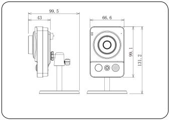
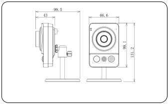
Figure 2 IP Camera Dimensions
5
IP Camera Installation
After reading the installation instructions and before installing your IP camera, prepare a plan for mounting the IP camera at your protected site. Correct placement of your IP camera is crucial for optimal security-monitoring performance. First, determine which areas need to be protected and then map out the most optimal areas for installing your IP camera.
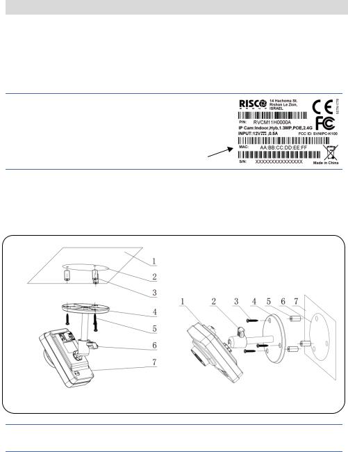
IMPORTANT! – Please make a record of the MAC address located on the box or on the back cover of the IP camera before installation. You may need it during the network connection stage.
MAC address
Mounting the IP Camera
The IP camera support two mounting options; ceiling and wall mount (see Figure 3 and Figure 4, below).
Figure 3 Ceiling Mount |
Figure 4 Wall Mount |
IMPORTANTPlease make sure the installation surface can support at least 3 times the weight of the camera and the bracket.
6
Step |
Description |
1 |
Place the installation positioning template on the installation surface such as |
|
ceiling or wall. |
2 |
Make holes in the installation surface according to the installation positioning |
|
template. |
3 |
Insert the expansion bolts from the accessories bag into the holes you just made. |
4 |
Position the IP camera base over the holes |
5 |
Use the screws from the accessories bag to secure the IP camera firmly. |
6 |
Loosen the adjust knob and adjust the IP camera to the correct surveillance |
|
position according to your actual requirements. |
7 |
Secure the adjust knob to fix the IP camera. |
Powering-up the IP Camera
1.Connect the provided electrical power adapter to the Power port on the IP camera.
2.Connect the power adapter to an electrical outlet. When the IP camera boots up, the GREEN power indicator light turns on.
Connecting the IP Camera to the Network
The IP camera supports several network connection options including LAN and Wireless.
Connecting to a LAN Network
Connecting the IP camera to a network using the LAN (Local Area Network) enables easy connection and setup with compatible APs (Access Points), e.g. gateway or router.
1.Connect the incoming network cable to the Network port on the IP camera.
2.Wait just a few minutes while the IP camera automatically connects to the RISCO Cloud. The RED network indicator light indicates that your IP camera is now ready for defining camera settings (Refer to Defining IP Camera Settings).
7

Connecting to a Wireless Network using WPS
Connecting the IP camera to a wireless network using WPS (Wi-Fi Protected Setup) requires that the router and Operating System supports WPS functionality.
NOTE – Some routers have a virtual button on their management software. (Refer to the router’s documentation for details about using its WPS functions).
1.Once the power cord is connected, wait for 5 minutes for the camera to boot up.
2.Press and hold down the WPS button on the IP camera and the WPS button on the router respectively for 2 seconds. The GREEN network indicator light indicates that your IP camera is now ready for defining camera settings (Refer to Defining IP Camera Settings).
Connecting to a Wireless Network using the RISCO Cloud
Connecting the IP camera to a wireless network using the RISCO Cloud (RISCO Application Server) requires that you first physically connect the IP camera to the router and then, from the RISCO Cloud Installer Application, define the IP camera settings and establish a wireless connection. Once a wireless connection has been established the IP camera can then be disconnected from the router and installed.
1.Connect the incoming network cable to the Network port on the IP camera.
2.Wait just a few minutes while the IP camera automatically connects to the RISCO Cloud (RISCO Application Server). The RED network indicator light indicates that your IP camera is now ready for defining camera settings (Refer to Defining IP Camera Settings).
3.Once a wireless connection has been established, disconnect the IP camera from the router and install it anywhere within the monitored area.
8
IP Cameras and the RISCO Cloud Installer Application
The RISCO Cloud Installer Application provides an interface to your control panel from a local or remote PC via the Web. This enables you to add IP cameras and define camera and event alarm trigger settings.
IMPORTANT – A control panel must first be defined in RISCO Cloud in order to accept IP cameras and define camera settings (Refer to the RISCO Cloud Installer Application Manual)
Defining IP Camera Settings
Once you have connected the IP camera to the network (refer to, Connecting the IP Camera to the Network) you can define the camera settings.
To define IP camera settings:
1.Log into the Installer Administration application using the Web page address supplied by your service provider and enter your user name and password.
NOTE – It is recommended to use Google Chrome or Mozilla Firefox to log into the Installer Administration application.
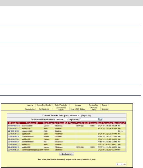
2.Select the Control Panels List link. The Control Panels List page is displayed.
Figure 5 Control Panels List Page
3.From the Control Panels List page, select the Control Panel you wish to view. The Control Panels Update page is displayed.
9
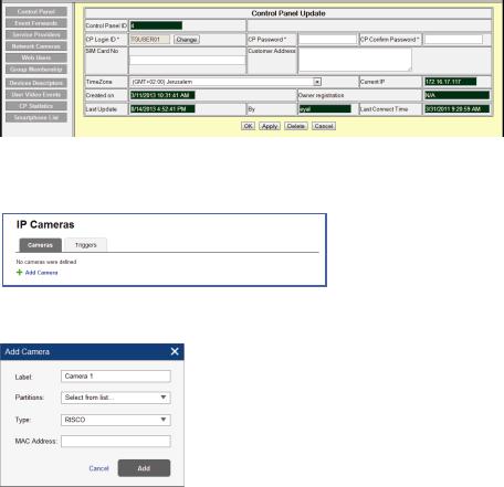
Figure 6 Control Panel Update Page
4.Click the Network Cameras link in the left-hand column; the IP Camera List page is displayed.
Figure 7 IP Cameras List
5.Click Add Camera; the Add Camera dialog box is displayed.
Figure 8 Add Camera
6.Define the following fields in the Add Camera dialog box.
Field |
Description |
Label |
Enter a name for the camera |
Partitions |
Select the partition(s) from the list of defined partitions |
Type |
Choose the RISCO camera type (for ON |
|
VIF or Generic camera type settings, refer to the RISCO Cloud Installer |
|
Application Manual) |
MAC |
Enter the MAC address into this field. The MAC address (media access |
Address |
control address) is the unique identifier assigned to the IP camera for |
|
communications on the physical network. |
|
NOTE: The MAC address is case sensitive and should be entered exactly as |
|
it is shown on the box or on the back cover of the IP camera, e.g. |
|
AA:BB:CC:DD:EE:FF |
|
10 |
7.Click Add.
If the “Camera was identified successfully” message is displayed, go straight to step 8.
Figure 9 Camera was identified successfully message
If an “unable to configure Internet Access”, “UPnP Client Error” or similar message is displayed, refer to the Troubleshooting section.
NOTE – This message is only relevant for IP cameras that are physically connected to the LAN network via the router.
8.Select one of the following options:
Connect to Wi-Fi – to establish a wireless network connection (go to step 9 to connect the IP camera to the wireless network).
Not Now – to establish a LAN network connection (skip the wireless network connection steps 9, 10 and 11 and connect the IP camera to the LAN network).
9.If you selected the “Connect to Wi-Fi” option, a list of available wireless networks is displayed.
Figure 10 List of available wireless networks
10. Select a wireless network from the available list and click Connect.
11

NOTE – If your network is password protected, a password must be entered into the displayed password screen.
11.Click OK to establish the wireless connection (Refer to Connecting to a Wireless Network using the RISCO Cloud).
IMPORTANT – Once a wireless connection has been established, don’t forget to disconnect the IP camera Ethernet cable from the router.
12.Once the “camera is ready for use” message is displayed, click OK. The defined IP camera is displayed in the IP Cameras page.
Figure 11 IP Camera List
NOTE – You also have the option to edit 
 or delete

 the selected IP camera.
Defining Camera Trigger Settings
Any event from the following list can be defined to trigger an alarm.
Partition Events
Fire Alarm |
Panic Alarm |
Medical Alarm |
Alarm |
Full Arm |
Part Arm |
Disarmed |
Duress |
Tamper |
24 HR-X Alarm |
Water Alarm |
Gas Alarm |
Environ. Alarm |
No Motion Alarm |
Exit Alarm |
Low Temperature |
|
Detector Events |
|
|
Alarm |
Zone Bypassed |
Zone Un-bypassed |
Zone Tamper |
12

To define camera trigger settings:
1.From the Control Panel Cameras page, click the Triggers tab, the Camera Triggers List page is displayed.
Figure 12 Camera Triggers List
2.Click Add Trigger; the Add Triggers dialog box appears.
Figure 13 Add Trigger
3.Define the following fields in the Add Trigger dialog box:
Field |
Description |
Event Type |
Label |
Enter a name for the camera trigger |
Partition and Detector events |
Camera |
Choose a camera from the list |
Partition and Detector events |
Event Type |
Choose an event type from the list |
Partition and Detector events |
Event |
Choose the event from the list, e.g. |
Partition and Detector events |
|
alarm, duress, etc. |
|
13

Additional fields are displayed in the Add Trigger dialog box according to the event type that you selected (see examples below for Partition and Detector event types).
Figure 14 Add Partition Event Trigger |
Figure 15 Add Detector Event Trigger |
4.Define the following fields in the Add Trigger dialog box according to the event type that you selected.
Field |
Description |
Event Type |
Partition(s) |
Select the partition(s) from the list. |
Partition events only |
|
NOTE – Only partitions associated with |
|
|
the camera are displayed. |
|
Detectors |
Select the detector from the list |
Detector events only |
5.Define the following image (still) and clip (video) definitions:
Field
Images (still)
Clips (video)
Description
Pre-event starting time (sec) – time, before the actual event occurred, to start displaying still images.
Number of images – number of still images to display.
Interval between images (sec) – time required between each still image.
Pre-event starting time (sec) – time, before the actual event occurred, to start displaying video clip.
Duration (sec) – total duration of the video clip
NOTE – These fields are currently locked and the default parameters cannot be changed.
14

6.Once finished, click Done. The defined camera trigger is displayed in the Camera Triggers List page.
Figure 16 Camera Triggers List
NOTE – You also have the options to edit |
|
, create a duplicate |
|
, or to delete |
|
|
the selected camera trigger. |
|
|
|
|
|
|
|
|
||
IMPORTANT – No two camera triggers can be defined as identical. If a camera trigger is duplicated, the event, camera or both definitions must be changed.
15

Troubleshooting
Internet Configuration/UPnP Client Error
Not all routers support UPnP and in some routers UPnP is disabled by default. If you have tried configuring internet access automatically and get the message “unable to configure Internet Access”, “UPnP Client Error” or similar, it should possible to set your IP cameras and router up manually.
Step1: Login to your router
Use the router interface to identify the camera’s IP address. The Router Interface can be opened using any standard web browser.
1.Enter the local IP address of the router into the web browser’s address field. The Router Interface Login page is displayed.
2.Enter your username and password in the Login box that appears and click OK/Login.
NOTE: For more information on how to navigate your specific router please check the router’s User manual.
3.Navigate to the DHCP Client Table. The DHCP Client Table page is displayed.
Figure 17 DHCP Client Table page
4.Make a note of the IP Address of the camera that you want to setup manually.
Step 2: Camera Settings
Use the Camera Interface to setup the camera. The Camera Interface can also be opened using any standard web browser.
1.Enter the IP address and the web port of the camera, for example 192.168.010.168:37080 (default web port is 37080).
NOTE – When using more than one camera the default web port shouldn’t be the same
16

2.Once the Camera Interface Login page is displayed, enter the User and Password into the relevant fields and click Login.
NOTE – By Default the User and Password for camera login is “admin” and “_AdmiN_+ camera MAC address” (e.g._AdmiN_AABBCCDDEEFF).
1.Once the Camera Interface page is displayed, select Setup > Network > UPnP. The UPnP Parameters page is displayed.
Figure 18 UPnP Parameters
2.Uncheck the UPnP Enable option and click Save.
3.Select TCP/IP. The TCP/IP Parameters page is displayed.
Figure 19 TCP/IP Parameters
4.Select the Static Mode option and enter the static IP address you want to set for the camera (in our example 192.168.1.122). Also set the subnet mask and Default gateway address (in our example 255.255.255.0 and 192.168.1.1).
17

NOTE: By default the TCP/IP settings should already be defined.
5.Click Save to save the changes.
6.Select Connection. The Connection Parameters page is displayed.
Figure 20 Connection Parameters
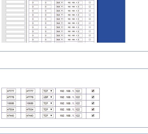
7.Set the following port connection parameters of the camera:
TCP Port Set the TCP port you want to define for the camera (in our example 47777).
UDP Port Set the UDP port (in our example 47778)
HTTP Port The default port number is 80, and can be changed to any port range 1024 to 65535 (in our example 10080).
RTSP Port: The default port number is 554 (in our example 47554).
HTTPS Port The default port number is 443, and can be changed to any port range 1024 to 65535 (in our example 47443).
8.Click Save to save the changes.
9.Repeat the above steps for each camera using the relevant IP address and alternative port number for each.
Step 3: Router Port Forwarding Settings
By default, the security features on many routers prevent access to the devices on your home/business network from the Internet. To open a port, you need to enable “port forwarding” on your router. Router administration screens can vary, but typically, you would do the following to open a port:
1.Return to the Router Interface page.
NOTE: For more information on how to navigate your specific router please check the routers User manual.
18
2.Navigate to the Advanced Setup > Port Forwarding/Port Triggering. The Port Forwarding page is displayed.
Figure 21 Port Forwarding page (empty)
NOTE: This is the section in the router where we will specify which local IP address belongs to which external port number. Make sure that “Port forwarding” is enabled for each IP address.
3.For the first camera enter the settings as shown in the screenshot below. Remember to use the same local IP address and external port numbers as was set in the camera settings in Step 2.
Figure 22 Port Forwarding page (populated)
NOTE: For HTTP, RTSP and HTTPs Port settings use the TCP Protocol option.
4.Click Apply/Save Settings to save the changes.
5.Reboot the camera by unplugging and reconnecting the camera to the power supply.
6.Repeat the above steps for each camera using the same local IP address and external port numbers as was set in the camera settings.
19

Product Specification
Parameter |
|
|
|
|
||
System |
|
|
Main Processor |
TI Davinci high performance DSP |
|
|
|
|
OS |
Embedded LINUX |
|
||
|
|
|
|
|||
|
|
|
System Resources |
Support real-time network monitor, local record, and remote operation at the |
||
|
|
|
same time. |
|
||
|
|
|
|
|
||
|
|
|
User Interface |
Remote operation interface such as WEB, DSS, PSS. |
||
|
|
|
System Status |
Bit stream statistics, log, and software version. |
||
Video |
|
|
Image Sensor |
1/3-inch CMOS |
|
|
|
|
Pixel |
1280(H)*960(V) |
|
||
Parameter |
|
|
Gain Control |
Fixed/Auto |
|
|
|
|
|
|
|||
|
|
|
White Balance |
Manual/Auto |
|
|
|
|
|
BLC |
On/Off |
|
|
|
|
|
|
Manual/Auto |
|
|
|
|
|
Exposure Mode |
PAL: It ranges from 1/3 to 1/10000. |
|
|
|
|
|
|
NTSC: It ranges from 1/4 to 1/10000. |
||
|
|
|
|
PAL: |
|
|
|
|
|
|
Main stream(1280*960@15fps) |
|
|
|
|
|
|
extra stream(352*288@15fps), |
|
|
|
|
|
|
Main stream(1280*720@25fps |
|
|
|
|
|
Video Frame Rate |
extra stream(352*288@25fps |
|
|
|
|
|
NTSC: |
|
||
|
|
|
|
|
||
|
|
|
|
Main stream(1280*960@15fps) |
|
|
|
|
|
|
extra stream(352*240@15fps)) |
|
|
|
|
|
|
Main stream(1280*720@30fps) |
|
|
|
|
|
|
extra stream(352*240@30fps) |
|
|
|
|
|
|
H.264: 56Kbps-6144Kbps |
|
|
|
|
|
Video Bit Rate |
JPEG is adjustable and bit rate is adjustable. |
||
|
|
|
|
Support customized setup. |
|
|
|
|
|
Video Flip |
Support mirror. |
|
|
|
|
|
Support flip function. |
|
||
|
|
|
|
|
||
|
|
|
Snapshot |
Max 1f/s snapshot. File extension name is JPEG. |
||
|
|
|
Privacy Mask |
Supports max 4 privacy mask zones |
|
|
|
|
|
Video Setup |
Support parameter setup such as bright, contrast. |
||
|
|
|
Video Information |
Channel title, time title, motion detect, camera masking. |
||
|
|
|
Lens |
3.6mm. Fixed focus. Angle of view: 70°(H *51.5°(V) |
||
|
|
|
Lens Interface |
M12. Lens is the default accessories |
|
|
Audio |
|
|
Audio Bit Stream |
Dual-way |
|
|
|
|
Audio Input / Output |
Built-in microphone and speaker |
|
||
|
|
|
|
|||
|
|
|
Audio Bit Rate |
8kbps 16bit |
|
|
|
|
|
Audio Compression |
G.711A/G.711Mu/PCM |
|
|
|
|
|
Standard |
|
||
|
|
|
|
|
|
|
Video |
|
|
N/A |
N/A |
|
|
|
|
|
|
|
|
|
|
|
|
|
Sensitivity level ranges from 1 to 6. Each sensitivity level is the percentage of |
||
|
|
|
|
the privacy mask zone. |
|
|
|
|
|
Camera Masking |
Activation event: alarm device, audio/video storage, image snapshot, log, email |
||
|
|
|
|
SMTP function and etc. |
|
|
|
|
|
|
|
||
Alarm Port |
|
1-channel input and 1-channel output (on-off ) |
||||
and Backu p |
Record |
|
Record Priority |
Support remote record only |
|
Manual>Video detect>Schedule |
|
SD Card Storage |
Support Micro SD card hot-swap |
|
|||
|
|
|
|
|||
|
|
|
Storage Management |
Support display network storage status |
||
20
Parameter |
|
|
|
Network |
|
Wire Network |
1-channel wire Ethernet port, 10/100 Base-T Ethernet |
|
Wireless Network |
IEEE802.11a/b/g/n, built-in antenna |
|
|
Network Protocol |
Standard HTTP, TCP/IP, ARP, IGMP, ICMP, RTSP, RTP,UDP, RTCP, SMTP, |
|
|
|
FTP, DHCP, DNS, DDNS UPNP, NTP, Bonjour, SNMP. |
|
|
|
|
|
|
|
Remote Operation |
Monitor, system setup, file download, log information, maintenance , upgrade |
|
|
IR light |
and etc. |
AUX |
|
|
White light (Max 1W) |
|
Compensation Light |
Auto turn on white light when an alarm is activated. The light can last until the |
|
|
alarm ends. |
||
Port |
|
|
|
|
|
Support compensation light brightness setup via the Web. |
|
|
N/A |
N/A |
|
|
|
||
|
|
|
|
|
|
WPS |
Click one button to enable WIFI connection |
General |
|
|
DC 12V |
|
Power |
Warning |
|
|
Do not connect these two power supplying sources to the device at the same |
||
|
|
||
|
|
time; it may result in device damage! |
|
Parameter |
|
Power Consumption |
6W MAX |
|
Working Temperature |
-10 ~+50 |
|
|
Working Humidify |
10%~90% |
|
|
|
Dimensions(mm) |
66.6*99.5*131.2 |
|
|
Weight |
229g Excluding box |
|
|
Installation |
Installation with the bracket. |
21

NOTES
22
VUpoint Caméra IP
Intérieure Cube
Modèle: RVCM11H
Guide d’Installation

Précautions d’Usage
Ces instructions sont destinées à faire en sorte que l'utilisateur puisse utiliser le produit correctement pour éviter le danger ou la perte matérielle.
MISES EN GARDE:
L’installation ou l'utilisation de ce produit sans respecter l'usage prévu tel que défini par le fournisseur et comme décrit dans les matériels pédagogiques peut entraîner des dommages, des blessures ou la mort.
Assurez-vous que ce produit n'est pas accessible par les enfants et à ceux pour qui le fonctionnement du système n'est pas destiné.
Toute installation et utilisation doivent être conformes aux codes de sécurité électrique locaux. L’alimentation doit être conforme à l'exigence de la SELV (Safety Extra Low Voltage) et la source d'alimentation 12 V DC limitée s'est vu attribuer l’IEC60950-1.
Si le dispositif est relié en permanence à une source d'alimentation électrique, la connexion doit comporter un dispositif de déconnexion facile d'accès, tel qu'un disjoncteur. Ne pas connecter les deux sources d’alimentations à l'appareil en même temps, cela peut causer des dommages de l'appareil!
Ne jamais tenter de réparer votre appareil vous-même, car cela peut entraîner des dommages, des blessures ou la mort - toujours contacter votre agent installateur/fournisseur pour la maintenance.
AVERTISSEMENTS:
Assurez-vous que la tension d'alimentation est correcte avant d'utiliser la caméra.
Ne pas laissez tomber la caméra ou la soumettre à des chocs physiques.
Ne touchez pas les modules capteurs avec les doigts. Si un nettoyage est nécessaire, utilisez un chiffon propre avec un peu d'éthanol et essuyez.
Ne pas exposer l'objectif de la caméra à une forte lumière, comme le soleil ou une lampe à incandescence. La lumière forte peut causer des dommages mortels à la caméra.
Le capteur peut être brûlé par un faisceau laser, si un appareil laser est utilisé, assurez-vous que la surface du capteur ne soit pas exposée au faisceau laser.
Ne pas exposer la caméra à des températures extrêmes froides ou chaudes (la température de fonctionnement doit être comprise entre -10 ° C à +50 ° C).
Pour éviter l'accumulation de chaleur, une bonne ventilation est nécessaire pour un bon environnement d'exploitation.
Gardez la caméra loin de l'eau et de tout liquide.
Pendant son transport, la caméra doit être emballée dans son emballage d'origine.
NOTE: Nous n'assumons aucune responsabilité pour tous les incendies ou les chocs électriques causés par une manipulation ou une mauvaise installation. Nous ne sommes pas responsables des problèmes causés par une modification non autorisée ou tentative de réparation.

Introduction
RISCO Group présente VuPoint, une solution de vérification de la vidéo en direct révolutionnaire qui intègre de façon transparente les caméras IP au sein de nos systèmes de sécurité professionnels. Géré par RISCO Cloud, VuPoint offre un niveau de sécurité sans précédent en offrant la surveillance vidéo en direct aux stations de télésurveillance et aux utilisateurs commerciaux/résidentiels. La Caméra IP cube intérieure de RISCO est une partie importante de cette solution et est facilement contrôlé par les applications Smartphone et Web intuitives de RISCO.
Caractéristiques
•Installation Simple ‘Plug & Play’
•1.3” Mégapixel
•Couleur HD
•Slot carte SD pour stockage local
•Wi-Fi
Composants et Accessoires
Caméra IP RISCO et support de montage:
Chargeur électrique et sac d'accessoires d'installation:
Guide d’Installation:
3

Composants Caméra IP et Dimensions
Figure 1 Composants Caméra IP
Indice |
Nom Port |
Indicateur |
Connecteur |
Description |
|
1 |
Voyant |
ALIM |
/ |
Lors du démarrage de la caméra – |
|
Allumée verte. |
|||||
|
d'alimentation |
|
|
||
|
|
|
Lorsque la caméra est en mise à |
||
|
|
|
|
||
|
|
|
|
jour - verte clignotante. - Intervalle |
|
|
|
|
|
de 0.5s. |
|
|
|
|
|
Lorsque la caméra est en alarme - |
|
|
|
|
|
verte clignotante. |
|
|
|
|
|
Intervalle de 0.2s. |
|
|
|
|
|
|
|
2 |
Voyant de |
RESEAU |
/ |
Connexion réseau filaire - allumée |
|
rouge. |
|||||
|
réseau |
|
|
||
|
|
|
Connexion réseau sans fil – allumée |
||
|
|
|
|
||
|
|
|
|
verte. |
|
|
|
|
|
|
|
3 |
Haut-parleur |
/ |
/ |
Signal audio de sortie (Cette fonction |
|
est optionnelle). |
|||||
|
|
|
|
||
|
|
|
|
|
|
4 |
Lumière blanche |
/ |
/ |
Peut s’activer sur détection de |
|
mouvement IRP, détection du |
|||||
|
|
|
|
||
|
|
|
|
mouvement corps humain, alarme |
|
|
|
|
|
externe. |
|
|
|
|
|
|
|
5 |
N/A |
N/A |
N/A |
N/A |
|
|
|
|
|
|
|
6 |
Microphone |
/ |
/ |
Recevoir directement le signal audio |
|
(Cette fonction est optionnelle). |
|||||
|
|
|
|
||
|
|
|
|
|
Indice |
Nom Port |
Indicateur |
Connecteur |
Description |
||
7 |
Carte Micro SD |
Micro SD |
Logement |
Carte SD stockage. |
||
Caractéristiques Micro SD: |
||||||
|
|
|
carte Micro |
|||
|
|
|
Type: class 4 |
|||
|
|
|
SD |
|||
|
|
|
Capacité: jusqu’à 64GB. |
|||
|
|
|
|
|||
|
|
|
|
NOTE: L’ajout de carte micro SD |
||
|
|
|
|
permet d’étendre la capacité |
||
|
|
|
|
d’enregistrement de clips vidéo |
||
|
|
|
|
|
||
8 |
Bouton Reset |
Reset |
/ |
Restaurer la configuration d'usine par |
||
défaut. Lorsque le système fonctionne |
||||||
|
|
|
|
|||
|
|
|
|
normalement, maintenir appuyé le |
||
|
|
|
|
bouton RESET pendant au moins 5 |
||
|
|
|
|
secondes, le système peut restaurer la |
||
|
|
|
|
configuration d'usine par défaut. |
||
|
|
|
|
|
||
9 |
Bouton WPS |
WPS |
Connexion |
Appuyez sur le bouton WPS du |
||
routeur et du périphérique |
||||||
|
|
|
sans fil rapide |
|||
|
|
|
respectivement pendant au moins 2 |
|||
|
|
|
|
|||
|
|
|
|
secondes. Habituellement, le |
||
|
|
|
|
dispositif se connecte au routeur en 1 |
||
|
|
|
|
minute. |
||
|
|
|
|
Veuillez noter s'il vous plaît que ceci |
||
|
|
|
|
ne s’applique qu’à un routeur sans fil |
||
|
|
|
|
avec fonctionnalité WPS. |
||
|
|
|
|
|
|
|
10 |
N/A |
N/A |
N/A |
N/A |
|
|
|
|
|
|
|
||
11 |
Port |
DC12V |
/ |
Entrée Alimentation 12V DC. |
||
|
Alimentation |
|
|
|
|
|
|
|
|
|
|
|
|
12 |
Port Réseau |
LAN |
Port Ethernet |
|
Connecter un câble Ethernet |
|
|
standard. |
|||||
|
|
|
|
|
||
Figure 2 IP Dimensions Caméra
5

Installation Caméra IP
Après avoir lu les instructions d'installation et avant d'installer votre caméra IP, préparer un plan de montage de la caméra IP correspondant au site à protéger. L’emplacement correct de votre caméra IP est crucial pour une performance optimale de surveillance et de sécurité. Tout d'abord, déterminer les zones qui doivent être protégées et faire un plan des zones optimales pour l'installation de votre caméra IP.
IMPORTANT! – S'il vous plaît, veuillez noter l'adresse MAC située sur la boîte ou sur la couverture arrière de la caméra IP avant installation. Vous pourriez en avoir besoin au cours de la phase de connexion réseau.
Adresse MAC
Montage de la Caméra IP
Le support de caméra IP autorise deux options de montage; plafond et support mural (voir Figure 3 et Figure 4, ci-dessous).
Figure 3 Montage Plafond |
Figure 4 Montage Mural |
IMPORTANT- S'il vous plaît assurez-vous que la surface de montage peut supporter au moins 3 fois le poids de la caméra et de son support.
6
 Loading...